1
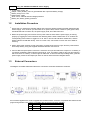
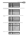
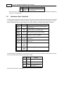
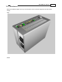
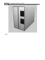
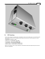
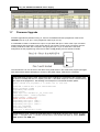
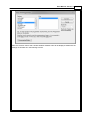
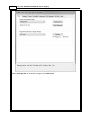
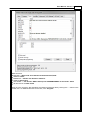
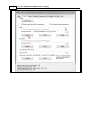
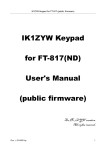
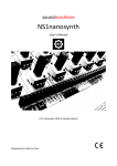
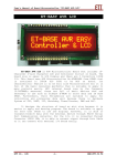
User Manual: Version 1
1
User Manual: Version 1
1.1
Overview
1
WARNING: This is product has exposed mains power inside the enclosure. Certain tracks on the PCB and
the heatsinks contain live AC. Do not open the enclosure unless properly qualified to do so, and then only
when mains is disconnected and the power supply has had time to dissipate the power stored in its
capacitors. In the event that a foreign object gets into the power supply (by means of the air vents or any
other opening in the enclosure), immediately disconnect the power supply and return to SSE for servicing.
The SSE Switched-mode Power Supply product was designed to replace the existing SSE power supply. It
improves over the previous design in terms of improved operating efficiency, lower heat generation and
intelligent monitoring. The new design has the ability to communicate its current state in real time to the
attached RTU, giving a user the ability to monitor and log voltages and currents as well as battery and AC
state. It also adds cost flexibility by allowing different internal OEM PSU units to be selected depending on
application requirements. Finally, the new power supply was designed to be easier and quicker to
manufacture and service.
Features:
Supports various OEM PSU units
Monitoring of main power output voltage and current
Monitoring of battery charge / load voltage and current
Monitoring of AC and battery status
Low current 5V output
Individual output and status indicators
Separate switches and fuses for RTU and panel power
Fused AC input
Simplified wiring
Free air convection cooling
Battery backup (UPS) capability (using a seal lead-acid battery)
DIN rail mounted
Supports old, current and next generation RTUs
Specifications:
Base PCB designed to support 7A panel power output and 4A RTU power output
Note: each individual connector pin can only support max 5A
Max measurable current: 10A (panel and RTU combined), 3.5A (battery charge)
Max measurable voltage: 14V (panel / RTU and battery)
5V ouput: 1A max
Single 13.8V (12V) SLA battery only
Power supply specifications are determined by the OEM PSU module used. Here are specifications for two
recommended models:
Mean Well PSC-60
Input: 90~264VAC, 47~63Hz
Typical input current: 1.6A
Output: 13.8V (tunable), max 4.3A (split between DC output and battery charge)
Battery charge: max 1.5A
Rated power: 60W
Short circuit, overload and over-voltage protection
Battery low, battery polarity protection
Mean Well PSC-100
Input: 90~264VAC, 47~63Hz
2
737_132: SSE Switched-Mode Power Supply
Typical input current: 2A
Output: 13.8V (tunable), max 7A (split between DC output and battery charge)
Battery charge: max 2.5A
Rated power: 100W
Short circuit, overload and over-voltage protection
Battery low, battery polarity protection
1.2
Installation Procedure
1. Ensure that you have all the required cabling and connectors before installing the SSE Switched-mode
Power Supply. As a minimum you will need: an AC power cable, RTU12 or RTUxxx (new) power cable,
4x2 Molex MicroFit connector kit, the power supply itself, and a DIN rail mount.
2. Mount the power supply and connect the AC power cable. Ensure that the power supply is working
properly by toggling the rocker switches and observing LEDs. LEDs should switch on or off when the
corresponding rocker switch is toggled on or off. The 5V and AC OK indicators should be lit, and the
Status indicator should flash slowly. If this is not the case, check fuses or return the unit to SSE for
servicing.
3. Switch both rocker switches to their 'off' position, and disconnect the AC input. Wire the panel devices
and backup battery using the supplied 4x2 Molex MicroFit connector kit.
4. Connect RTU and panel power connectors. Attach the AC input and switch the outputs on. If a battery is
connected, the Battery Status indicator should be lit. If not, the battery might be very low (and charging wait a few hours to confirm), or there might be cable fault. To fine-tune the output voltage level, open the
power supply enclosure and adjust pot SVR1 on the DC side of the PSU daughter-board.
1.3
External Connectors
The diagram and tables below describe all the connectors accessible outside the enclosure.
J1: Firmware Upgrade Port: used to upgrade CPU board firmware. Connector compatible with SAM and LPC
programming headers. Pins 3-8 are compatible with the Atmel AVR ICSP standard.
Pin
Name
1-2 NC
3
MISO
Notes
Not used
Data out
User Manual: Version 1
4
Vcc
Voltage detect
5
SCK
Clock
6
MOSI
Data in
7
Reset
Programmer reset circuit
8
GND
Ground
9-10 NC
3
Not used
J2: RTU Bus Power and Comms: supplies power to RTU Bus devices, used to communicate with existing
RTU models (RTU12 and earlier).
Pin
Name
Notes
1
SDA
I2C data
2
SCL
I2C clock
3-15 NC
Not used (on power supply side)
16- GND
21
Ground
22- 12V-14V
26
Power out to RTU devices (12V to
14V, 5A max)
J4: RTUxxx Power and Comms: supplies power and communicated with new RTU models (currently
unnamed).
Pin
Name
1-2 12V-14V
Notes
Power out to RTUxxx devices (12V
to 14V, 5A max)
3
GND
Ground
4
SDA
I2C data
5
SCL
I2C clock
6
GND
Ground
J5: Panel Power Output: supplies power to external devices, also connects to the backup battery.
Pin
1
Name
Batt
Negative
2-4 GND
Notes
Connect to the negative terminal of
one 13.8V SLA battery only
Ground
5
Batt
Positive
Connect to the positive terminal of
one 13.8V SLA battery only
6
12V-14V
Power out to external devices (12V
to 14V, 5A max)
7
12V-14V
Power out to external devices (12V
to 14V, 5A max)
8
5V
Power out to external devices (5V,
1A max)
J8: Mains In: connects to main AC power source.
Pin
1
Name
AC Live
Notes
Universal input support (90-264
VAC, 47-63 Hz)
4
737_132: SSE Switched-Mode Power Supply
2
AC Earth Earth to power supply
3
AC
Universal input support (90-264
Neutral
VAC, 47-63 Hz)
o NB: connect to a power source that can produce more than 2A constant. See OEM power supply data
sheet for more information.
1.4
Hardware User Interface
The front panel of the power supply contains 6 LEDs and two switches. RTU power and Panel power outputs
are individually switched by the rocker switches. LEDs indicate the state of the 3 power output lines (RTU
power, Panel power and 5V output), battery or AC fault conditions, and basic power supply condition.
Item
Name
LED 1 Green
AC OK
Lit when AC is connected, off when battery
backup is used
LED 2 Green
Battery
Low
Lit when battery is connected, off when level
battery is very low or disconnected
LED 3 Red
Status
Slowly flashes during normal operation
LED 4 Green
Description
5V Output Lit when 5V output is available
LED 5 Green
RTU
Power
Lit when RTU power output is available and
switched on
LED 6 Green
Panel
Power
Lit when Panel power output is available and
switched on
Switch 1
RTU
Power
Switch
Switches RTU power
Switch 2
Panel
Power
Switch
Switches Panel power
On the downward facing edge of the power supply enclosure are three fuse holders. These contain fuses for
the RTU and Panel power outputs, and for the AC input.
Fuse
Front
Name
Panel
fuse
Middle RTU
fuse
Back
See 'Enclosure' section for images.
Rating
5A
5A
AC fuse 2A or 3A depending on
PSU model
User Manual: Version 1
1.5
Enclosure
Below are rendered images of the top, front and bottom of the enclosure designed for the SSE Power
Supply.
Top:
Front:
5
6
Bottom:
737_132: SSE Switched-Mode Power Supply
User Manual: Version 1
1.6
7
OPC Interface
Power supply analogue and digital values are available in OPC via the IO Maps page. A user should map the
following source data types into predefined AINs and DINs, after which they can be treated as any other
AINs or DINs.
AC OK -> PSU MAINS OK (DIN)
Battery OK -> PSU BATTERY LOW (DIN)
Load current -> PSU LOAD CURRENT (AIN)
Load voltage -> PSU LOAD VOLTAGE (AIN)
Battery current -> PSU BATTERY CURRENT (AIN)
Battery voltage -> PSU BATTERY VOLTAGE (AIN)
Below is an example of such a setup. Remember to download AIN, DIN and IO Map descriptors to the RTU
after OPC configuration.
8
1.7
737_132: SSE Switched-Mode Power Supply
Firmware Upgrade
Firmware upgrades are performed using J1. Connect a standard AVR ISP-II programmer cable to the
CENTRE 6 pins of J1 (ie: pin 1 of the programmer cable to pin 3 of J1).
It is advisable to create a converter from 6 pin to 10 pin ribbon with pins 1 and 2 of the 10-pin connector
shorted (pins 9 and 10 left open). This can be done by just crimping a new (10 pin) connector onto the
existing AVR ISP-II cable, with a loop-back wire going from pin 1 to pin 2. Note: this is the same
arrangement as the programming connector for SSE's Look@ display and Low Power Controller.
The new firmware can now be sent to the device using AVR Studio or the stand-alone program packaged
with new firmware. Before attempting to connect to the power supply, make sure it is powered.
If the stand-alone program is used, make sure that the AVR ISP-II is connected to the computer (and
its driver is installed) and then run "Update_PSU.bat". A file called "output.txt" will be created showing
the output of the programmer. The following is an example of a successful firmware update:
STK500 command line programmer, v 2.3 Atmel Corp (C) 2004-2009.
Connected to AVRISP mkII on port USB:0000B0012964
Device parameters loaded
Programming mode entered
Device erased
FLASH input file SSE-SMPS-737_132_V1.hex read
Programming FLASH... FLASH programmed
Reading FLASH... FLASH read
FLASH verified successfully
Programming fuse byte 0 (0xE2)...
Programming fuse byte 1 (0xDF)...
Programming fuse byte 2 (0xF9)...
Fuse bits programmed
Programming mode left
Connection to AVRISP mkII closed
If AVR Studio is used, connect the AVR ISP-II and run AVR Studio. Click the "Con" button, or select
"Tools" -> "Program AVR" -> "Connect" from the menu. In the window that pops up, select "AVRISP
mkII" platform and "USB" port.
User Manual: Version 1
Click the "Connect" button and a window entitled "AVRISP mkII" will be displayed. Make sure the
settings are entered as in the following screens:
9
10
737_132: SSE Switched-Mode Power Supply
Select "ATmega168" as the device to program and "ISP mode".
User Manual: Version 1
11
Make sure that:
BOOTSZ = "Boot Flash size=1024 words start address=$1C00"
SPIEN is ticked
BODLEVEL = "Brown-out detection disabled"
CKDIV is NOT ticked
SUT CKSEL = "Int. RC Osc. 8MHz: Start-up time PWRDWN/RESET: 6 CK/14 CK + 65ms"
All other boxes are NOT ticked
Then go to the "Program" tab and select the newest firmware hex file by clicking the "..." button in the
"Flash" box. To download firmware to the LPC, click "Program".
12
737_132: SSE Switched-Mode Power Supply