1
24pin Dot Matrix Printer
CP-9000K
USER'S MANUAL
JOLIMARK
* Epson is a registered trademark of S.Epson Corporation.
* LQ-2550 is a registered trademark of S.Epson Corporation.
* IBM is a registered trademark of International Business Machines Corporation.
* IBM2931 is a registered trademark of International Business Machines Corporation.
* Windows is a registered trademark of Microsoft Corporation.
CP-9000K
USER'S MANUAL
24-pin wide-carriage
dot matrix printer
Contents
Unpacking
the
p r i n t e r. . . . . . . . 1
Quick
s t a rt u p......................................... 2
1. Introduction
Features. . . . . . . . . . . . . . . . . . . . . . . . . . . . . . .. 3
Options and expendables. . . . . . . .. . . . .. .. . . .. 4
Printer description. . . . . . . . . . . . . . . . . . . .. . .. . 6
2. Setting up
Installing the paper rack . . . . . . . . . . . . .. .. . . . . 1 0
Installing the sound seal cover
. . . . . ...... 1 0
Installing the ribbon cassette
. . .. . . . . . . . 11
Connecting the computer . . . . . . . . . . . .. .. . . . . 1 2
Connecting the power cord . . . . . . . . . . . . . . . . 1 2
Loading the paper . . . . . . . . . . .. . . . . . . .. . . . . . 1 3
Adjusting print head position . . . .. . . . . . . . .. . . 1 5
3. Control panel and operations
Control panel and indicators
...........16
Paper parking . . . . . . . . . . . . . . . . . . . . . . . . . . .. . . . . . 2 0
Printing test pattern . . . . . . . . . . . . . ... . . . . . . . . 2 1
Demonstration print-out . . . . . . . .. . . . . . . . . . . . 2 2
Tearing off a form . . . . . . . . . . . .. . . . . . .. . . . . . . 2 2
Power-on operation summary
. .. . .. . . . . . 2 3
4. Basic setup options
About basic setup options . . . . . . . . . . .. . . . . . . 2 4
Printing multipart paper . . . . . .... . . . . . . . . . . . . 2 6
Selecting page length
for fanfold paper. . . . . . . . . . . . . . . . . . . . . . 2 6
Selecting single sheet
paper size . . . . . . . . . . . . . . . . . . . . . . . . . . 2 7
Selecting font style . . . . . . . . . . . . . . . . . . . . . . 2 8
Selecting character spacing
...........29
Enlarging/compressing print . . . . . . . . . . . . . . . 3 0
Setting top of form position . . . . ... . . . . . . . . . . 3 1
Loading user setup options
............31
5. Extended setup options
About extended setup options
. . . .. . ... . . 3 3
Print
enhancement
1 0 Emulation........................... . . . . . . . . ......... 3 6
1 2 Character table (Epson mode). . . . . . . . . . . 3 7
1 3 Character table (IBM mode). . . . . . . . . . . . . 3 7
1 4 National font style............ . . . . . . . ............. 3 8
1 5 Code page............................ . . . . . . . ........ 3 8
1 6 IBM Alternate graphic mode. . . . . .. . . . . . . 3 9
1 7 Carriage return (CR)......... . . . . . ............... 3 9
1 8 Line feed (LF)................ . . . . . . . ................ 3 9
1 9 Line feed spacing.......... . . . . . . ................. 4 0
2 0 Slashed zero.................... . . . . . . . ............. 4 0
2 1 Set default tab stops............. . . . . . . .......... 4 0
2 2 Lock-in the page length..... . . . . . . ............. 4 0
2 3 Print quality ........................ . . . . . . . . ........ 4 1
2 4 Lock-in the font.................. . . . . . . . . ......... 4 1
2 5 Lock-in the character
spacing ............................ . . . . . . . . . ........ 4 1
2 6 Lock-in the print quality...... . . . . . . . ............ 4 1
Barcode
print
enhancement
2 7 Enable barcode print ............. . . . . . . . . . . ........ 4 2
2 8 Barcode type..................... . . . . . . . . . . . ........... 4 2
2 9 Bar code size.................. . . . . . . . . . . . ............... 4 4
3 0 Enlarged character size....... . . . . . . . . . ............. 4 4
3 1 Graphic Print Speed ......... . . . . . . . . . . .............. 4 5
3 2 Accent character.............. . . . . . . . . . . . .............. 4 5
3 3 Setting of the FF code at TOF . . . . . . . . . . . . . . . . 4 5
Paper
handling
enhancement
4 0 Set the top margin.............. . . . .. . . . . . . . ........... 4 7
4 1 Set the bottom margin ..... . . . . . . . . . . . .............. 4 7
4 2 Set the left margin............... . . . . . . . . . . . . .......... 4 7
4 3 Set the right margin ....... . . . . . . . . . . . . ............... 4 8
4 4 Fanfold paper width ....... . . . . . . . . . . . . .............. 4 8
4 5 Autoscroll delay........ . . . . . . . . . . . . .................... 4 8
4 6 Override bottom margin ..... . . . . . . . . . . . ........... 4 9
4 7 Label mode....................... . . . . . . . . . . . . ........... 4 9
4 8 Paper out detection ....... . . . . . . . . . . . ................. 5 0
4 9 Cut sheet feeder type ....... . . . . . . . . . . ............... 5 0
5 0 Setting of the auto
scrolling position ..... . . . . . . . . . . . . ............ 5 0
5 1 Line Feed Speed.......... . . . . . . . . . . ................... 5 1
Communication
enhancement
6 0 Interface type............. . . . . . . . . . . . ................... 5 1
6 1 SELECT IN signal.......... . . . . . . . . . . . ................ 5 1
6 2 Parity bits..... . . . . . . . . . . . . . .............................. 5 1
6 3 Data length......... . . . . . . . . . . . . ......................... 5 2
6 4 Stop bit............. . . . . . . . . . . . . . ......................... 5 2
6 5 Communication protocol . . . . . . . . . . . . . . . . . . . . 5 2
6 6 Communication speed .... . . . . . . . . . . . ............... 5 2
6 7 Serial error check ..... . . . . . . . . . . . . .................... 5 3
6 8 CTS signal ............ . . . . . . . . . . . . ...................... 5 3
6 9 CD signal .......... . . . . . . . . . . . . ......................... 5 3
7 0 DSR signal............ . . . . . . . . . . . . ...................... 5 3
7 1 Communication buffer size
............ . . . . . . . 5 4
7 2 Busy/ACK timing........ . . . . . . . . . . . .................. 5 4
7 3 Data latch timing........ . . . . . . . . . . . ................... 5 4
7 4 Setting of whether ERROR/PE
signals are output or not
...........54
Miscellaneous
8 0 Print direction............ . . . . . . . . . . . . .................. 5 5
8 1 LCD display language...... . . . . . . . . . . ............... 5 5
8 2 Invert LCD display ....... . . . . . . . . . . . ................ 5 5
8 3 Software controlled setup . . . . . . . . . . . . . . . . . . . 5 6
8 4 Lock the RESET key......... . . . . . . . . . . .............. 5 6
8 5 Setting of ENERGY STAR . . . . . . . .. . . . . . . . . . . 5 6
8 6 Saving user setup options . . . . . . . . . . . . . . . . . . 5 6
8 7 Printing list of option settings
. . . . . . .. . . . . 5 6
6. Setting the application software
About printer driver . . . . . . . . . . . . . . . . . . . . . . 5 7
Printer driver selection . . . . . . . . . . .. . . . . . . . . 5 7
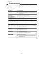
7. Troubleshooting
Error messages . . . . . . . . . . . . . . . . . . . . . . . . . 6 0
Troubleshooting guide . . . . . . . . . . . .. . . . . . . . 6 1
Input hexadecimal dump mode
. . . . . . .6 2
8. Maintenance
Cleaning. . . . . . . . . . . . . . . . . . . . . . . . . . . . . . . 6 3
Lubrication. . . . . . . . . . . . . . . . . .. . . . . . . . . . . . 6 3
Printer cover removal . . . . . . . . . . . . . . . . . . . . . 6 4
Vertical alignment mode
..............66
9. Bar code and enlarged
character function
Bar
codefunction
Outline of bar code function......... . . . . . . . .. . . . 6 9
Makeup of bar code................... . . .. . . . . . . . . . 6 9
Bar code command list........... . ............. . . . . . .. 7 0
(1) Bar code type.......... . . . . . . ............... 7 0
(2) Element width........ . . . . . . . ............... 7 1
(3) Bar code height.................. . . . . . . . . .7 1
(4) Setting HRI on and off......... . . . . . . ... 7 1
(5) HRI font.............. . . . . . . . ................. 7 2
(6) Check character.................. . . . . . ...7 2
(7) Starting the bar code data sequence. .. 7 2
(8) Ending the bar code data sequence. . . 7 3
(9) Bar code data sequence......... . . . ..... 7 3
(10) Printing density...... . . . . . . . ............. 7 3
(11) Guide bar expansion...... . . . . ......... 7 3
(12) Start and stop characters.... . . . ...... 7 4
(13) Barcode rotational angle...... . . . . .... 7 4
(14) Disabling HRI of the start
and stop characters.... . . . . ..... 7 4
(15) Value input mode....... . . . . . ............ 7 4
(16) Initializing the bar code mode. . . . .. . 7 5
Data processing in the bar
code data sequence.... . . ........ 7 5
Printing bar codes.......... . . . . . ........... 7 6
HRI........................ . . . . . . . ............... 7 6
Error processing.......... . . . . . ............. 7 7
Code 128 subset transition rule. . . . . . 7 7
UPC-E conversion rule........ . . . . ...... 7 8
Calculating the check character. . . . . . 7 8
Other.............................. . . . . . . . . . . . . . . ....... 8 0
Element printing.......... . . . . . . . . . . . . . . ......... 8 0
Enlarged
character
function
Outline of enlarged
characterfunction...... . . . . . . . . . . ....... 8 2
Enlarged character
command list......... . . . . . . . . . . . ......... 8 2
(1) Executing backspacing.... . . . . . . . . . . . . ........ 8 3
(2) Executing line feeding...... . . . . . . . . . . . ........ 8 3
(3) Executing form feeding...... . . . . . . . . . . . ....... 8 4
(4) Executing carriage return.... . . . . . . . . . . ....... 8 4
(5) Initializing the enlarged
character mode....... . . . . . . . . . . ......... 8 4
(6) Arrangement of enlarged
characters............ . . . . . . . . . . . .......... 8 5
(7) Cell magnification for
enlarged characters......... . . . . . . . . . . .......... 8 5
(8) All-character set for
enlarged characters....... . . . . . . . . . . . ............. 8 6
(9) Selecting an enlarged
character font............... . . . . . . . . . . . . ........... 8 6
(10) Height expansion for
enlarged characters........... . . . . . . . . . . ........ 8 7
(11) HMI for enlarged characters. . . . . . . . . . . .
87
(12) VMI for enlarged characters. . . . . . . . . . . . . 8 8
(13) Setting and canceling the
enlarged character mode. . . . . . . . . . . 8 8
(14) Enlarged character cell offset. . . . . . . . . . . . 8 9
(15) Enlarged character pitch.... . . . . . . . . . . ...... 8 9
(16) Enlarged character quality. . . . . . . . . . . . .. . .9 0
(17) Enlarged character rotational angle. . . . . . .. 9 0
(18) Setting and canceling enlarged
character smoothing. . . . . . . . . 9 1
(19) Enlarged character top offset. . . . . . . . . .. . . 9 1
(20) Setting and canceling underlining
of enlarged characters. . . . . . . . . 9 2
(21) Enlarged character
widthwise expansition.. . . . . . . . . . ...... 9 2
(22) Horizontal printing position
for enlarged characters.. . . . . . . . .. 9 3
(23) Vertical printing position for
enlarged characters. . . . . . . . 9 3
Enlarged character print samples. . . . . . . . .. . 9 4
Appendices
A. Specifications
Printing specifications . . . . . . .. . . . . . . . . . 9 5
Parallel interface
specifications . . . . . . . . . . . . . .. . 1 0 0
Serial interface
specifications . . . . . . . . . . . . . .. . 1 0 1
Other specifications
. . . ..... . . . . . . . 1 0 2
B. Control code summary
IBM mode . . . . . . . . . . . . . . . . . . . . . . .. . 1 0 3
Epson mode . . . . . . . . . . . .. . . . . . . . .. . . 1 0 9
Setup options control codes . . . . . . . . . . 1 2 2
C. Character sets. . . . . . . . . .. .. .. . . . .. . .. . . 1 2 7
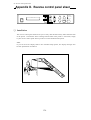
D. Reverse control panel
...
......136
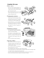
Caution for use
❏ Power sourc e
• Be sure to insert the power plug only in a
wall unit of the voltage designated in the
voltage selector switch and on the rating
plate on the back of the unit.
• Do not place the power cord near heat
sources or place heavy objects on it. Do not
bend or twist the power cord.
❏ Foreign matter and water
• Keep your hands and personal items, such as
scarfs and ties, away from the carriage
mechanism while the printer is operating.
The carriage moves with considerable force.
• Keep the printer dry. If you accidentally
spill water on the machine, turn the power
off immediately and wipe it dry. Do not turn
the power on until the machine is
completely dry.
❏ Installation environment
• The printer should be used where humidity is
low, where there is little dust, and where the
printer is not in direct sunlight.
• Avoid placing or leaning anything on top of
the printer. If you accidentally drop any
object into the machine, turn the power off
immediately, then carefully remove the
object.
• Do not twist the ribbon while installing it.
❏ Operating condition
• Wait at least two seconds after turning power
o ff b e f o r e t u r n i n g i t b a c k a g a i n . T h e
initialization process may not be performed
correctly if this is not done.
• Do not touch the print head immediately
after printing because it is too hot.
• Never operate the printer without paper or paper properly installed.
If you use paper that is not as wide as the platen, be sure that printing does not exceed paper width.
Use software control to change the width of the print line.
• Never insert or pull out an interface cable while the power to the printer and computer is on.
• Be sure to turn off the printer before turning off a connected host computer.
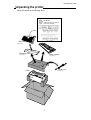
Unpacking the printer
Unpacking the printer
Check the cartons for the following items:
(Driver-CD with User’s Manual,
printer driver software)
Paper Rack
(See page 10)
Sound Seal Cover
Ribbon Cassette
(See page 10)
(See page 11)
Power Cord
Printer
(See page 12)
1
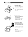
Quick startup
Quick startup
To make your first print, follow the procedure below . For more detailed instructions on setting your
printer, please refer to the page indicated.
❏ To set up the printer
1. Install the paper rack, the sound seal cover,
and the ribbon cassette — Pages 10 and 11.
2. Load the single cut sheet paper or fanfold
paper. Press the FF key to load the paper —
Pages 13 and 14.
❏ To make a test print
Self
Test
Self
Test
1. Set the paper size of the printer in the setup
options — Pages 26 and 27.
2. Press the LF key and hold while initializing
the printer by the RESET key. Hold the LF
key until the self test starts — Page 21.
?
?
❏ To connect your computer
1. With all equipment turned off, connect the
?
?
?
?
printer to your computer. Interface cable is
purchased separately — Page 12.
2. Use the extended setup options (emulation
type and communication enhancement
section) to match the specification needs
between the printer and your computer —
Pages 33 to 56.
3. Select the printer driver from your
application software — Page 57.
2
1. Introduction
1. Introduction
Features
Barcode Print available
• 13 resident barcode type
Industrial 2/5, Interleave 2/5, Codabar, Matrix 2/5, Code 11, Code 39,
Code 93, Code 128, EAN-8, EAN-13, UPC-A, UPC-E, Postnet
Enlarged character printing
Characters can be enlarged (by up to 127 times as large x 127 times as
large) using the enlarged character command unique to this printer.
Software commands are used for control.
Contain the 2 kind of emulations
Compatible to major printer emulations, Hewlett Packard, IBM and Epson printers.
• EPSON
LQ-2550 compatible
• IBM
2391 compatible
Wide selection of paper size
• Single cut sheet papers
• Fanfold continuous paper
• Multi-part paper
• Labeling paper
A3, A4, B4, B5, Letter, Legal
5 - 15 inch wide and 2 - 16.5 inch long paper
Original plus 8 copies (total clearance: 0.635mm (0.025”)
Label peel-proof capability
Full option of font types and variation of character pitch
• 10 resident fonts
• 8 character pitch
Courier, Prestige, Script, OCR-A, OCR-B, Gothic, Orator, Orator-S,
Roman, and Sans Serif
10, 12, 15, 17.1, 20, 24 characters per inch (CPI), and
proportional and 1/2 proportional characters
Enlarge/reduce your layout to fit in any paper size
• you can print the same layout of the document in different paper size.
Easy operation
• Multiple display language for international use.
• Upside down display enables operation from the back of the printer.
Superb compatibility and connect ability
• Communication protocols adjustable to any computer.
• Interface connections provided for parallel, RS-232C.
• Parallel and serial interface are switched automatically when "AUTO" setting is selected.
3
1. Introduction
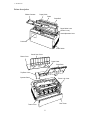
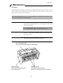
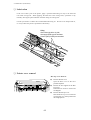
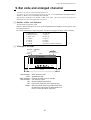
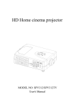
Printer description
Ribbon Cassette
Paper Guide
Platen
Paper Bail
Paper Select Lever
(Friction Lever)
Head Adjustment Lever
Print head
Power Switch
Sound Seal Cover
Printer Cover
Paper Cutter
Paper Rack
Top Rear Cover
Operator Panel
Tractor Lock Lever
Rear Cover
Tractor Cover
6
1. Introduction
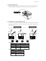
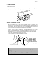
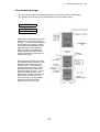
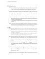
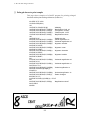
❏ Operation guide sheet
The operation guide sheet helps you to operate some of the basic options on the front control panel.
You can peel the adhesive backed paper and stick it anywhere on your printer for convenience.
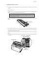
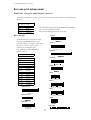
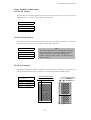
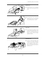
❏ Precaution for extra-thick paper usage
Extra-thick continuous paper, especially 9-part multi-layer paper may get jammed in the printer due
to its stiffness and inflexibility. When using such paper, set the paper rack in the slant position
shown in the figure.
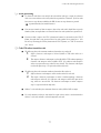
Push Tractor Method
• Multiple Fanfold Paper
• Label Fanfold Paper
Print Head
Friction Feed Method
• Single ply Fanfold Paper
• Single Sheet Paper
Print Head
Print Head
Platen
Tractor
Tractor
Friction Roller
Fanfold Paper
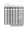
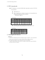
Description
Single-ply
Multiple Copies Label Paper
Paper width
5~15 inch
Paper length
2~16.5 inch
Ply
single
Original+8 max.
single
Total thickness 0.065~0.12mm 0.635mm max. 0.18mm max.
Paper weight
14lbs.~28lbs.
non-carbon
125Kg max.
53g/m2 ~105g/m2
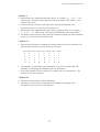
Single Sheet Paper
Description
Paper size
Ply
Total thickness
Paper weight
Single-ply
A3, A4, B4, B5 Letter, Legal
single
0.08~0.12mm
17lbs.~28lbs.
64g/m2 ~105g/m2
7
1. Introduction
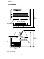
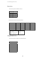
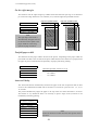
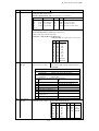
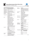
Physical dimension
24 .4" (620mm)
17.9"
(455mm)
19.9"
(505mm)
Paper Rack in flat position
(Continuous paper setting)
Sound Seal Cover
Paper Rack in upright position
(Single sheet setting)
15.4"
(390mm)
Paper Rack in flat position
(Continuous paper setting)
11.6"
(295mm)
10.2"
(260mm)
12.0"
(305mm)
Weight: 44.1 lbs. (20 kg)
8
17.1"
(435mm)
2. Setting up
2. Setting up
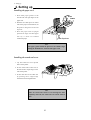
Installing the paper rack
1. Slide both paper guides to the
Pivots
extreme left and right edges of the
Groove
paper rack.
2. With the two small pivots on either
2
1
side of the paper rack downward, fit
the pivots in the groove on the rear
top cover.
3. Place the paper rack in upright
position for single cut sheet paper
and lay it down for fanfold
continuous paper.
Rear Top Cover
Note
The paper guides should be placed to the outside edges
during the installation or removal of the paper rack.
Installing the sound seal cover
1. Lay the sound seal cover upside
down on the printer.
2. Fit one of the holes of the cover to
the stud of the L-angle hinge on one
side of the printer.
3. Fit the other hole to the other stud
L-angle Hinge
by pressing the L-angle hinge
inward then out through the hole.
Note
Make sure that both studs are out through the hole
completely, otherwise, the sound seal cover will be stuck in
place.
10
2. Setting up
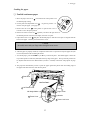
Installing the ribbon cassette
Turn OFF the printer's power and remove the used ribbon cassette, if necessary, by pulling straight
upward.
1. Open the printer cover.
2. Manually move the print head to the extreme right side of the printer for easy installation of the
ribbon. Do not try to move the print head if the power is on.
CAUTION
Do not touch the print head if the printer has been running for a long time. Wait
until the print head is cooled off.
3. Turn the ribbon feed knob in the direction of the arrow on the knob to remove any slack in the
ribbon.
Re
mo
ve
Ribbon Feed Knob
an
ys
lac
k fr
om
rib
bo
n
4. Place the ribbon cassette on the left and right cassette holders, such that the ribbon rests on the
ribbon guide. Check to be sure that the ribbon drive shaft on the left cassette holder is inserted in the
hole on the bottom of the ribbon cassette.
5. Turn the ribbon feed knob in the direction of the arrow on the knob to remove any slack in the
ribbon.
6. Replace the front printer cover and set the head adjustment lever to the proper position for the best
print quality.
Ribbon Guide
Ribbon Mask
Cassette Holders
Cassette Holder
11
2. Setting up
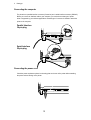
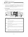
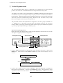
Connecting the computer
The printer has a parallel interface connector (Centronics) and a serial interface connector (RS232C).
Before you connect an interface cable to your computer, you need to know what type of printer
driver is supported by your software applications and what type of connector is needed to attach the
printer to the computer.
Parallel Interface
36-pin plug
CAUTION
1
13
220-240V
120V
14
25
Serial Interface
25-pin plug
CAUTION
13
220-240V
1
120V
T5A 250V
25
14
T2.5A 250V(For European)
Connecting the power cord
Check the power requirement printed on the rating plate on the rear of the printer before attaching
the power cord and turning on the printer.
N
o
t
e
12
2. Setting up
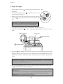
Loading the paper
❏ Fanfold continuous paper
1. Move the paper select lever
toward the front of the printer to set
1
the fanfold paper setting.
2. Set the print head adjustment lever
. In general, position 1 is
2
used for one-part paper. (See page 15)
3. Remove the rear cover
of the printer or open the rear cover to
lock the cover in the open position.
4. Release the tractor lock levers
(upward), and move the right tractor to
the marked position as shown in the figure, and lock it in place.
5. Open both tractor covers
and place the fanfold paper so that the tractor pins are aligned with the
holes in the paper. Carefully close both tractor covers.
Caution
Be careful not to catch your finger when closing the tractor covers.
6. After the paper is properly installed, re-adjust the left tractor to a position to keep the paper taut (but
not too taut) between the left and right tractors.
7. To load the paper, press the PARK key or FF key on the front panel. The fanfold paper is fed to the
top-of-form position 14/60 inch (6mm)below the top edge of the paper. The top-of-form position can
be adjusted from 0/60 inch to 480/60 inches (8 inches = 203mm) in the basic setup options on page
31.
8. The paper bail automatically lowers to press the paper against the platen when the leading edge of
the paper feeds more than one inch onto the platen.
3
Rear Cover
Not Too Taut !!
5
Left Tractor Cover
Left Margin Marker
Right Tractor
Releasing direction
5
Tractor Cover
4
13
Tractor Lock Lever
2. Setting up
❏ Single sheet paper
1. Move the paper select lever
toward the rear of the printer to the single
sheet setting.
2. Set the print head adjustment lever
1
. In general, position 1 is used
for one-part paper. See page 15.
3. Raise the paper rack to the vertical position and adjust the left
paper guide
2
to the proper position for the size of the paper being
used.
Note
If the paper is not loaded on the proper mark, the printer
may not detect the paper and will issue PAPER ERROR.
4. Place single sheet paper against the paper rack and let it slide behind the platen.
5. Adjust the right paper guide
so that it comfortably holds the paper in between the two paper
guides.
Paper Size Marker
Extension Arm
4
A3
3
Right Paper Guide
B4
Left Paper Guide
6. Press the PARK key or FF key to load the single sheet paper to the top-of-form position 14/60 inch
(6mm) below the top edge of the paper. The top-of-form position can be adjusted from 0/60 inch to
480/60 inches (8 inches = 203mm) by using the front panel controls in the basic setup options on
page 30.
Note
If the paper is not completely fed in, slightly push the paper downward. If it is still not fed in,
look in the TROUBLESHOOTING section.
7. The paper bail automatically lowers to press the paper against the platen when the leading edge of
the paper feeds more than one inch onto the platen.
Notes
1. Extension Arm
The extension arm is used to keep large size (Legal, B4) single sheets from falling behind the
paper rack. When using the extension arm, pull the arm until it clicks and locks in place.
2. TEAR OFF keys are invalid with single sheet paper.
14
2. Setting up
❏ Paper alignment
Current print line location
The current printing line (DDD...) is the third line down from the top of the ribbon guide (line
spacing is 1/6 line: 6 LPI).
Ribbon Guide
0.5
A
A A A
A A
A AB B BC
B
C
C DC D D
D
Adjusting the print head position
The head adjustment is used to obtain the best print quality possible for the specific paper
being used. The print head position can be adjusted to accommodate printing on single and
multipart forms. When using multipart forms, move the print head adjustment lever toward the
front of the printer to widen the gap between the print head and the platen.
In general, position 1 is used for one-part paper. Moving the head adjustment lever one notch
adjusts the print head gap an amount corresponding to the addition of one more paper part.
Re-adjustment of the lever may be required depending on the quality of the actual printout:
• If the ribbon smears on the paper, the gap is too narrow.
• If the printed image is too light to read, the gap is too wide.
1
5
1
5
9
9
1 part-paper: 2nd click
5 part-paper: 8th click
9 part-paper: 13th click
(This scale is the suggested
number of sheets
for non-carbon part-paper.)
Head Adjustment Lever:
Move toward the front of
the printer for thicker paper
Notes
1. The print head adjustment lever should be set before loading the paper to avoid
paper jams.
2. If the printed image on the last copy of a multipart form is too light to read, set the
MULTIPART mode in the basic setup options (see page 26). This will increase the
striking intensity on multipart forms.
15
3. Control panel and operations
3. Control panel and operations
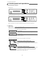
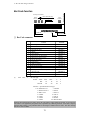
Control panel and indicators
Standard Panel
TOF SET
L
C
D
RESET
PARK
BIN
QUALITY
EXIT
ENTER
SETUP
ALT
M.LF
LF
FF
M.RLF
RLF
TEAR OFF
POWER
ON LINE
P.OUT
ON LINE
Alternate up-side down reverse panel
M.LF
M.RLF
RLF
TOF SET
BIN
PARK
QUALITY
EXIT
ENTER
SETUP
ALT
D
LF
C
ON LINE TEAR OFF
P.OUT
ON LINE
POWER
FF
RESET
L
Note: The alternate reverse panel installation instruction is described in Appendix D.
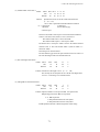
❏ Indicators
• Display window
Liquid Crystal Display (LCD)
Displays status and errors during operation and menus in the setup options.
The followings are some examples of the display messages.
P.OUT FANFOLD
Status message
This indicates that the printer is in offline and paper out status.
COVER OPEN
Warning message
This indicates that the printer cover is open. Close the cover to
resume the operation .
If the printer is in the offline mode, the following appears on the display.
FANFOLD 11 15
Status message for fanfold continuous paper
This column indicates the page length; and the paper widlh.
This indicates the type of paper selected is fanfold continuous
paper.
MANUAL:
A4
P
Status message for single sheets paper
This indicates a paper size; B5 through A3 depending on the
designated paper size (default A4) selected in the setup options.
This indicates the type of paper selected is single sheet paper.
MANUAL, BIN 1, BIN 2, BIN 1+2
16
3. Control panel and operations
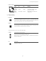
• Indicator lamps
POWER
ON LINE
P.OUT
Lamp
On
Off
Blinking
POWER
(green)
Power On
Power Off
ON LINE
(green)
Online
Offline
Cover open, or Head overheat
protection activating
P.OUT
(umber)
Out-of-paper
Paper-in
Home sensor error, RAM error,
or paper error.
—
ON LINE
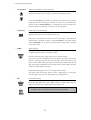
❏ Function Keys
• ON LINE
ON LINE
Pressing this key places the printer offline so that the printer can perform
some functions independent from the host system. In the offline mode, data
is not received. When the printer is offline, pressing the key places the
printer online and ready to receive data from the host system.
• RESET
When the RESET key is pressed, the printer immediately enters the reset
state and prepares for the initialize operation, which is nearly the same
initialize operation as when the power is turned on.
RESET
The following keys are active only in the offline mode:
• LF/RLF
LF
(Line feed and reverse line feed)
When the LF/RLF key is pressed, paper is fed per the line spacing at the 6
line per inch forward or backward, respectively.
While this key is pressed and held, the paper is continuously fed forward or
backward, respectively.
RLF
• FF
(Form feed)
Pressing this key feeds the paper to the next top of form position. Single
sheet paper is fed to eject.
FF
17
3. Control panel and operations
• M.LF/M.RLF
(Micro line feed/micro reverse line feed)
When the M.LF/M.RLF key is pressed, the paper is fed 1/360 inch forward
or backward, respectively. This key is used to set the paper position.
M.LF
M.RLF
• TEAR OFF
To set the TOF SET (top-of-form set) function, press the FF key and then
simply advance the loaded paper forward or reverse to your desired print
position using the M.LF/M.RLF keys. Hereafter until you reload paper, the
first print position of the form is always fed at the same place.
[Used only for fanfold paper]
Pressing this key advances the perforation of the form to the paper cutter so
that the leading form can be torn off from the rest.
TEAR OFF
If this key is pressed after the form is torn off, the paper is fed backwards
and the mode is returned to offline. If the ON LINE key is pressed instead
of the TEAR OFF key, the paper is fed backwards and the mode is changed
to the online mode.
• PARK
(Paper parking)
Pressing this key unloads the paper if the paper is already loaded and loads
the paper when the paper is not already loaded.
TOF SET
PARK
Fanfold continuous paper (paper select lever in fanfold setting)
The paper is moved to the park station in the back of the printer by pressing
this key. When pressing this key with the paper in the park position, the
paper will be loaded to the print station between 0 and 8 inches from the top
edge of the paper, depending on the loading position (TOF Adjust) selected
in the basic setup options on page 31.
Single sheet paper (paper select lever in single sheet setting)
The paper in the print station will be ejected. When paper is in the paper
rack, the paper is moved to the print station by pressing this key.
• BIN
BIN
EXIT
(ALT+SETUP keys)
This key is for selecting the active paper tray of the cut sheet feeder or the
paper feed type:MANUAL, BIN1, BIN2 or BIN1+2. BIN1, BIN2, BIN1+2
appears only when the cut sheet feeder (CSF) option is set.
SETUP
Note
+
ENTER
The paper select lever must be switched to the single sheet setting.
ALT
18
3. Control panel and operations
• TOF SET
(ALT+PARK keys)
The TOF SET key is valid only when paper is loaded. When the TOF SET
key is pressed in the offline state, the TOF position is set to the top of the
ribbon guide, and the buzzer
sounds.
TOF Position
Ribbon Guide
After two seconds, the paper is
fed backward so that the TOF
position is at the current
A
A A A
A A
printing position.
A AB B B
C
0.5 BCD CD DC D
Whe the TOF position is set, the
setting of “7 TOF ADJUST” is
changed to this set automatically.
TOF SET
PARK
+
ENTER
ALT
*TOF:Top of form
• SETUP
When the SETUP key is pressed the printer enters the setup options. The
setup options are explained later in the "Basic setup options" section.
BIN
EXIT
SETUP
• QUALITY
This key is for selecting the print quality: LQ, NLQ, HQDR (high quality
draft), DRAFT, SD (speed draft), or SSD (super speed draft). To set your
desired print quality simply scroll and stop where your selection is
displayed. The printer beeps once for an acknowledgment.
Software commands can override the print quality setting of this key.
However, "#26 Quality Lock" option described on page 41 can lock-in the
QUALITY
LCD
LQ
NLQ
HQDR
DRAFT
S.D.
S.S.D.
ESC x 1
ESC x 0
LQ is selected Draft is selected Graphic print speed
LQ
NLQ
LQ
LQ
S.D.
S.S.D.
Draft
Draft
HQDR
Draft
S.D.
S.S.D.
Normal✽
High speed 1
High speed 2
High speed 2
High speed 2
High speed 2
selection by this key and disable software commands.
This key also selects the graphic print speed.
*The graphic print speed is selected only by “31 GRAPHIC QUALITY”
in the extended setup options.
• Others
The ←, →, ↓, ↑ EXIT and ENTER keys become effective only in the setup options entered by
pressing the SETUP key. For more information refer to "Basic setup options."
❏ Control Levers
• Head adjustment Lever
This lever adjusts the gap between the print head and the platen. The correct
gap adjustment for a different paper thickness is required to obtain optimum
print quality. See also page 15.
1
5
9
19
3. Control panel and operations
• Paper Select Lever
The paper select lever serves to switch between the fanfold continuous paper
setting and the single sheet paper setting (or CSF setting when CSF
installed).
Note: Switching this lever to continuous paper setting will mechanically
release the pressure roller for single sheets and engage gear trains for
continuous paper.
Paper parking
This function moves fanfold paper back to the push tractor position (park station) so that single
sheet paper can be used. Specifically it is useful when switching from fanfold paper to single
sheet paper.
• Pressing the PARK key removes the fanfold paper from the print station so that single sheet
paper can be used.
• Switching of the paper select lever is required for the actual mechanical switching of the paper
select.
• Pressing the PARK key when the printer is in the paper-out state loads the selected paper
(fanfold or single sheet) to the top-of-form position.
The following table explains the paper handling of the PARK key in the offline state:
Friction Lever
Continuous Paper
Single Sheets
P.OUT Indicator
ON
OFF
ON
OFF
Action
Autoload the paper (similar to the FF key)
Park the paper in the push tractor position
Autoload the paper (similar to the FF key)
Eject the paper (similar to the FF key)
Notes
1. Make sure that the setting of the paper select lever corresponds to the type of paper
being used.
2. The paper park function causes PAPER ERROR in the following situations:
a) when the fanfold paper is not set in the park station (at the push tractors) after
moving more than 22 inches backward.
b) when the paper (fanfold or single sheet) is not autoloaded to the print station after
feeding more than 8 inches. (At this time, the printer tries to sense the paper in
the printer.)
c) when single sheet paper is not ejected from the printer after advancing more than
22 inches.
20
3. Control panel and operations
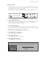
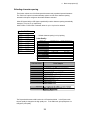
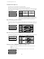
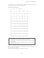
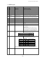
Printing test pattern
Before performing the printer's self test, be sure the ribbon cassette and paper are properly
installed in the printer. The self test prints a continuous pattern of printable characters (ASCII
character pattern) in either draft or letter quality (LQ).
While test printing is executed, the ON LINE lamp blinks and the LCD indicates “SELF TEST”.
TOF SET
SELF TEST DRAFT
RESET
PARK
BIN
QUALITY
EXIT
ENTER
SETUP
ALT
M.LF
LF
FF
M.RLF
RLF
TEAR OFF
POWER
ON LINE
P.OUT
ON LINE
❏ To run the draft self test
Press the LF key while turning ON the printer's power. If the printer is already turned ON, the
draft self test may be performed by pressing the LF key together with the RESET key.
Keep pressing the LF key until the self test begins.
❏ To run the LQ self test
Press both the LF and ON LINE keys simultaneously while turning ON the printer. If the
printer is already turned ON, the LQ self test may be performed by pressing both the LF and
ON LINE keys simultaneously together with the RESET key.
Keep pressing the LF and ON LINE keys until the self test begins.
❏ To stop the self test temporarily
Press the ON LINE key to stop printing.
❏ To resume the self test
Press the ON LINE key again to restart printing.
❏ To terminate this function
Press the RESET key or turn off the power.
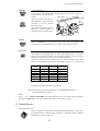
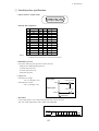
Note
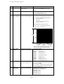
Before initiating the self test, make sure that the width of the paper, especially fanfold paper
loaded in the printer corresponds to the setting selected in the extended setup options.
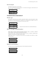
44 PAPER WIDTH
WIDTH:
WIDTH:
WIDTH:
15 IN
10 IN
5 IN
....................
....................
....................
Maximum printable columns at 10cpi
136 columns
80 columns
36 columns
21
3. Control panel and operations
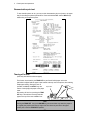
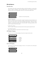
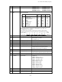
Demonstration print-out
To see what this printer can do, you may run this demonstration print-out (Letter or A4 paper
size) for checking the printer's performance. Press and hold the RLF and the M.RLF keys
while turning on the printer's power.
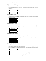
Tearing off a form
(Used only with fanfold continuous paper)
This function is activated by the TEAR OFF key and feeds fanfold paper so that the
perforation is aligned with the paper cutter located at the top rear of the printer, thus enabling
simple paper tearing. During the tear off
operation, the M.LF, and M.RLF keys are
Paper Cutter
used to correctly align the paper to the paper
cutter.
After tearing off the form, pressing the TEAR
OFF key a second time reversely feeds the
paper to the top of the next available form.
Note
Pressing the TEAR OFF key (or the ONLINE key) the second time may return the paper to
the original print position when the top edge of the form does not pass above the paper
location prior to the first TEAR OFF operation.
22
3. Control panel and operations
POWER
RESET
ALT
SETUP
TEAR OFF
RLF
M. RLF
M. LF
QUALITY
PARK
ON LINE
FF
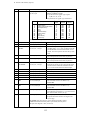
Operation (reference page)
LF
Power-on operation summary
Self test, draft (P21)
Self test,LQ (P21)
Hex dump, draft (P62)
Hex dump,LQ (P62)
Extended setup options (P33)
Demo printout (P22)
Loading MEMO 1 (P31)
Loading MEMO 2 (P31)
Loading MEMO 3 (P31)
Vertical alignment (P66)
EEPROM initialize 1
EEPROM initialize 2
Notes
1. Use either the RESET key or power switch when the circle is in both the RESET and
POWER columns.
2. EEPROM initialize 2 operation requires the vertical alignment operation after the
execution of the EEPROM initialize 2.
23
4. Basic setup options
4. Basic setup options
About basic setup options
The setup options serve to define various initial states of the printer that are executed when the
power is turned on or when the RESET key is pressed. In addition, this mode serves to
redefine the font type, character spacing, and other parameters for the printer's current
operating conditions. The parameters set in the setup options are stored in the memory of the
printer and used as the default values in initialize operations.
❏ To set this option
When the SETUP key is pressed in the offline mode, the printer enters the function setup
option, where various functions can be set. The keys used in the function setup mode are
described below.
Exit setup to offline
Select menu
Select function
TOF SET
MAIN SETUP
PARK
BIN
EXIT
RESET
SETUP
Choose selected function
QUALITY
M.LF
LF
FF
M.RLF
RLF
TEAR OFF
POWER
ON LINE
P.OUT
ENTER
ALT
ON LINE
Exit setup to online
← and →
[Alternate to the PARK and QUALITY]
These keys are used to go over menus in the display, but cannot be used to select
a menu item.
↓ and ↑
[Alternate to the M.LF/M.RLF]
These keys are used to go over items within a menu in the display, but cannot be
used to set an item parameter.
ENTER
[Alternate to the ALT]
When this key is pressed, an asterisk (*) indicating that the item is the currently
selected parameter is added at the end of the item.
EXIT
[Alternate to the SETUP]
When this key is pressed, the content of the item is stored in the memory of the
printer. Then, the printer exits from the setup options and enters the offline
mode.
ONLINE
This key's function is similar to the EXIT key in that the printer saves the
selected item and exits from the setup options. At that time, if no errors or
irregular conditions exist, the printer enters the online mode.
24
4. Basic setup options
❏ Selection procedure example
The following example illustrates the correct procedure to select a letter-portrait paper size
from the front panel:
1. Press the ON LINE key to enter the offline state. The ON LINE LED is put out:
2. Press the SETUP key to enter the SETUP options. The LCD displays:
1
MULTIPART
3. Press the Right Arrow (→) key to select the menu and to display:
3
PAGE SINGLE
4. Press the Down Arrow ( ↓ ) key to step down the function items, and to display:
SIZE:
LETTERp
5. Press the ENTER key to select letter-size portrait as the desired PAPER SIZE. The LCD
briefly displays the paper size with an asterisk at the end.
SIZE:
LETTERp*
6. Press the EXIT key to store the selection, terminate the setup options, and return to the offline
state or press the ON LINE key to return to the on line state.
❏ Setup Memory
Current memory
The printer contains one current memory for automatically storing the preset setup states and
three user memories for storing data that is designated by the user.
The current memory automatically stores the configuration when the setup options are
terminated. When the power is turned on or when the RESET key is pressed, the printer
automatically sets the configuration per the current memory. Thus, when entering the setup
options, the contents of the current memory can be altered.
User memory
The user memories can store three different configurations. The user can set and recall the
contents of the memory to configure the printer. When the power is turned on or when the
RESET key is pressed, the contents stored in the user memories are not used as the initial
values. To use the contents of the user memories as the initial values, it is necessary to select
one of the user memories, MEMO 1 to MEMO 3, in the setup options and evoke the contents as
the preset condition.
To use the contents of the user memory as the current setup, it is necessary to display the “8
SELECT SETUP” on the menu and select one of the user memories. Exiting from the setup
options with a user memory selected will cause the contents of the user memory to be stored in
the current memory which then becomes the printer initial values.
To store a configuration in a user memory, display the “86 SAVE SETUP” selection in the
extended setup options and select one of the user memories. The current setup content is stored
in the specified memory when exiting the setup options.
25
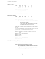
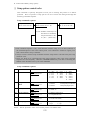
4. Basic setup options (1-2)
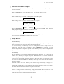
Printing multipart paper
The multipart mode increases the print intensity on multipart forms.
1
MULTIPART
COPY:
COPY:
COPY:
NORMAL
DARK 1
DARK 2
The followings will give an idea for proper selection:
........... Original + 5 copies
........... Original + 7 copies
........... Original + 8 copies
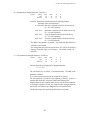
Selecting page length for fanfold paper
The page length selection varies from 2 inches to 16.5 inches with a 0.5 inch increment. The
page length is the same as the distance between two perforations.
The page length can be changed by software commands, but when the "Page Lock" option in
the extended setup options is set enabled, this page length selection becomes the fixed length
and software commands are ignored.
PAGE FANFOLD
PAGE:
PAGE:
PAGE:
PAGE:
PAGE:
2 IN
...
11 IN
...
16.5IN
TOF(Top Of Form)
Default page length is 11 inches
Printable area
2 - 16.5 Inch
Page length for fanfold paper
2
Perforation
Printable area
26
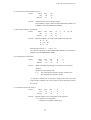
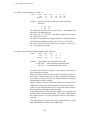
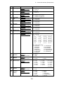
4. Basic setup options (3)
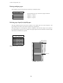
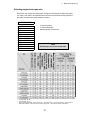
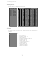
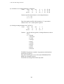
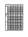
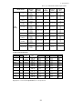
Selecting single sheet paper size
This function sets a paper size (page length, the right and left margins) of single sheet paper.
The "Page Lock" option in the extended options can lock-in the character spacing selected in
this option and ignores the related software command.
3 PAGE SINGLE
SIZE:
SIZE:
SIZE:
SIZE:
SIZE:
SIZE:
SIZE:
SIZE:
SIZE:
SIZE:
SIZE:
SIZE:
........... "P" denotes portrait.
........... "I" denotes landscape
........... Default page size is A4 portrait.
B5 p
B5 l
A4 p
A4 l
B4 p
B4 l
LETTERp
LETTERl
LEGAL p
LEGAL l
A3 p
A3 l
Maximum length
of page (mm)
1 68
1 98
1 80
A4 Portrait
A4 Landscape
1 114
B4 Portrait
1 98
B4 Landscape 1 136
Letter Portrait
1 82
Letter Landscape 1 108
Legal Portrait
1 82
Legal Landscape 1
136
A3 Portrait
1 114
A3 Landscape 1 136
B5 Portrait
B5 Landscape
Recommended
printing area
(length in mm)
Left Margin (chr.)
Paper Size
Recommended
Number of Columns
(chr./line)
Right Margin (chr.)
item
Note
A3 landscape can not be used with CSF.
Number of Lines / Page
EPSON/IBM
HP
Override OFF Override ON Override OFF Override ON
TOF Adj.
0/60" 14/60"
TOF Adj.
TOF Adj.
TOF Adj.
0/60" 14/60" 0/60" 14/60" 0/60" 14/60"
68
98
80
114
98
136
82
108
82
136
238
163
278
191
345
238
261
197
337
197
257
182
297
210
364
257
11"
8.5"
14"
8.5"
56
38
65
45
81
56
61
46
79
46
55
37
64
43
80
55
60
45
78
45
58
40
67
47
83
58
63
48
81
48
56
39
66
45
82
56
62
47
80
47
56
38
65
45
81
56
61
46
79
46
55
37
64
43
80
55
60
45
78
45
60
43
70
49
86
60
66
51
84
51
59
41
69
48
84
59
64
49
82
49
114
136
401
278
420
297
94
65
93
64
96
67
95
66
94
65
93
64
99
70
98
69
CONDITIONS
• Character Pitch: 10 CPI
• Line Feed Pitch: 6 LPI
• Page Length(in Epson/IBM) : = Paper form length - 0mm (top margin) - 17mm (bottom margin) - 2mm (tolerance)
• Right and Left Margin: correspond to the scale on the paper bail. (The unit is the number of characters).
27
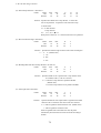
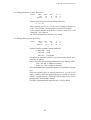
4. Basic setup options (4)
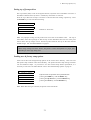
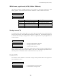
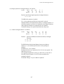
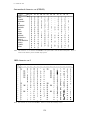
Selecting font style
This selection is effective only in the LQ or NLQ print mode.
provided.
There are 10 resident fonts
When the OCR-A or OCR-B font is selected, either 10 cpi or 12 cpi character spacing can be
selected. The "Font Lock" option in the extended options can lock-in the font selected in this
option and ignores the related software command.
4 FONT SELECT
FONT: ROMAN
FONT: S.SERIF
FONT:
FONT:
FONT:
FONT:
FONT:
FONT:
FONT:
FONT:
........... Default font is Roman.
........... Sans Serif
COURIER
PRESTIGE
SCRIPT
OCR-B
OCR-A
GOTHIC
ORATOR
ORATORs
Note:
1. If the current 'QUALITY' selection is SD, SSD, DRAFT, or
HQDR, the font selection depends on the EMULATION
currently selected:
EPSON or IBM mode — FONT SELECT selection will not
take effect until QUALITY selection is changed to either
NLQ or LQ.
2. If the current 'CHAR PITCH' is set to 15, 16, 17.1, 20, or
24 and OCR-A or OCR-B is selected, the ROMAN font
will be automatically substituted.
FONT
ROMAN
SANS SERIF
COURIER
PRESTIGE
SCRIPT
OCR-B
OCR-A
GOTHIC
PRINT SAMPLE
ORATOR
ORATOR-S
28
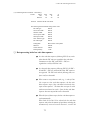
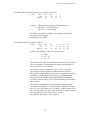
4. Basic setup options (5)
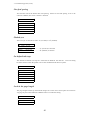
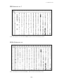
Selecting character spacing
This function selects one of the fixed spaced characters and proportional spaced characters.
The "Pitch Lock" option in the extended setup options can lock-in the character spacing
selected in this option and ignores the related software command.
When SD (speed draft) or SSD (super speed draft) is set the character spacing automatically
changes to 12 cpi or 15 cpi, respectively.
When OCR-A or OCR-B font is selected, either 10 cpi or 12 cpi can be selected.
5 CHAR PITCH
PITCH:
PITCH:
PITCH:
PITCH:
PITCH:
PITCH:
PITCH:
PITCH:
PITCH:
10 CPI
12 CPI
15 CPI
16.7 CPI
17 CPI
20 CPI
24 CPI
PROP.
1/2PROP.
........... Default character spacing is 10 cpi printing
Letter Quality
Character pitch
10 cpi
12 cpi
15 cpi (EPSON)
15 cpi (IBM)
16.7 cpi
17 cpi
20 cpi
24 cpi (EPSON)
24 cpi (IBM)
Proportional
1/2 Proportional
Character Pitch
Dot-spacing (V x H)
Character structure (V x H)
1/180 X 1/360
1/180 X 1/360
1/180 X 1/360
1/180 X 1/720
1/180 X 1/720
1/180 X 1/720
1/180 X 1/720
1/180 X 1/720
1/180 X 1/720
1/180 X 1/360
1/180 X 1/720
24 X 36
24 X 30
16 X 24
24 X 36(+12)
24 X 36(+7)
24 X 36(+6)
24 X 30(+6)
16 X 24(+6)
24 X 24(+6)
24 X N
24 X N
Print Sample
10 CPI
12 CPI
15 CPI (EPSON )
15 CPI (IBM)
16.7 CPI
17.1 CPI
20 CPI
24 CPI(EPSON )
24 CPI (IBM)
Proportional
1/2 Proportional
The Proportional character width is twice the 1/2 Proportional width. In the Epson mode,
the print quality is changed to the high quality one. In the IBM mode, print quality does not
change the print quality.
29
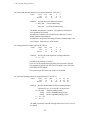
4. Basic setup options (6)
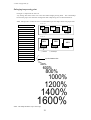
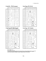
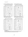
Enlarging/compressing print
Enlarges or compresses the text size.
Any setting other than 100% will cancel the double height printing mode. The relationships
between the paper sizes with their enlargement and compressing ratio are described below.
Note: Enlarge ratio of 200% or less is recommended to prevent single sheets from paper skew.
ZOOM OUT
6
ZOOM IN/OUT
66%
ZOOM OUT: 66
ZOOM OUT: 79
ZOOM OUT: 83
ZOOM OUT: 91
NO ZOOM: 100
ZOOM IN: 116
ZOOM IN: 120
ZOOM IN: 141
ZOOM IN: 200
ZOOM IN: 400
ZOOM IN: 600
ZOOM IN: 800
ZOOM IN: 1000
ZOOM IN: 1200
ZOOM IN: 1400
ZOOM IN: 1600
%
%
%
%
%
%
%
%
%
%
%
%
%
%
%
%
79%
B4
A3
B5
A4
B4
83%
A4
A4
A3
B5
B4
ZOOM IN
120%
116%
B5(p)
B4(l)
A4(p)
A3(l)
(p)=Portrait
A4(p)
B4(p)
141%
A4(p)
(l)=Landscape
66%
79%
83%
91%
4 point character size
100%
116%
120%
141%
200%
400%
600%
800%
1000%
1200%
1400%
1600%
Note: This sample illustrates only a scale image.
30
A3(p)
4. Basic setup options (7-8)
Setting top of form position
The top-of-form (TOF) can be set using this function, anywhere from a minimum of 0 inch to a
maximum of 480/60 inches (8 inches = 203mm) by increments of 1/60 inch.
Press the Up or Down arrow keys to increase or decrease the TOF setting, respectively. Press
the ENTER key to select the desired setting.
7
TOF ADJUST
TOF:
TOF:
TOF:
+ 0/60IN
+nnn/60IN ........... Defaults to 14/60 inch
+480/60IN
Note: Any improper setting of TOF position will set it back to the default value. The top of
form differs from the top margin in that the top of form determines the first line of the print
station where the top margin can be moved anywhere between the top of the form and the
bottom margin. See "40 TOP MARGIN" on page 47.
Note
When using settings less then 14/60", the printer is more susceptible to a paper jam,
depending on forms type being used.
Loading user & factory setup options
Loads one of three user designed setup options to the current active memory. This will erase
and replace setup contents in the current memory. The printer has three setup storage areas that
can store different setups. If you need to save the current setups before replacement, it is
necessary to select the “86 SAVE SETUP” item in the extended setup options on page 56.
8
SELECT SETUP
SETUP:
SETUP:
SETUP:
SET.:
MEMO 1
MEMO 2
MEMO 3
FACTORY
Equivalent short cut operation can be performed when:
........... pressing the PARK key with the RESET key,
........... pressing the QUALITY key with the RESET key,
........... pressing the M.LF key with the RESET key.
Note: When this setting is executed, the printer will be initialized.
31
4. Basic setup options (8)
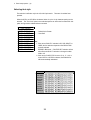
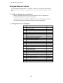
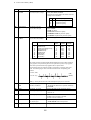
Factory Default Setting
Option Menu
Factory Default
Option Menu
Factory Default
<Basic options>
1 MULTIPART
2 PAGE FANFOLD
3 PAGE SINGLE
4 FONT SELECT
5 CHAR PITCH
6 ZOOM IN/OUT
7 TOF ADJUST
NORMAL
11"
A4 PORTRAIT
ROMAN
10 CPI
100%
14/60 INCH
<Extended options>
10 EMULATION
12 CHR TB EPSON
13 CHR TB IBM
14 NATIONAL FONT
15 CODE PAGE
16 AGM IBM
17 CR SETTING
18 LF SETTING
19 LF PITCH
20 ZERO STYLE
21 TABULATION
22 PAGE LOCK
23 QUALITY
24 FONT LOCK
25 PITCH LOCK
26 QLTY LOCK
27 BC/L.CHR
28 BC TYPE
29 BC SIZE
30 LARGE CH.SIZE
31 GR QLTY
32 ACCENT CHR
33 FF CODE/TOF
EPSON
ITALIC
SET 1
USA
437(USA)
NO
CR ONLY
LF+CR
6 LPI
NO-SLASHED
8 CHAR.
NO
LQ
NO
NO
NO
MODE 1
CODE39
1
8
MODE 2
SIMPLE
YES
40 TOP MARGIN
41 BOTTOM MARGIN
42 LEFT M.
43 RIGHT M.
44 PAPER WIDTH
45 AUTO SCROLL
46 OVERRIDE BM
47 LABEL MODE
48 P.OUT DTCT
49 CSF OPTION
50 SCROLL POS
51 LF SPEED
60 INTERFACE
61 SLCT IN CMD
62 PARITY BIT
63 DATA LENGTH
64 STOP BIT
65 PROTOCOL
66 BAUD RT
67 SERIAL ERROR
68 CTS ENABLE
69 CD ENABLE
70 DSR ENABLE
71 BUFFER SIZE
72 BUSY/ACK
73 DATA LATCH
74 ERROR STATUS
80 PRINT DIR
81 DISPLAY LANG
82 INVERT DISP
83 SOFTWARE SET
84 RESET LOCK
85 SLEEP MODE
0 LINE
0 LINE
0 COLUMN
0 COLUMN
15 INCH
NO SCROLL
YES
NO
ANY POS
NOT INSTALLED
ANY POS
NORMAL
PARALLEL
NO
NON
8 BITS
1 BIT
DTR
9600 BPS
PRINT *
NO
NO
NO
64 KB
TYPE 2
TYPE F
YES
BI-DIRECTION
ENGLISH
NO
YES
NO
YES
Option Menu
CURRENT
MEMO1
MEMO2
MEMO3
<Basic options>
4 FONT SELECT
ROMAN
COURIER
COURIER
COURIER
<Extended options>
10 EMULATION
18 LF SETTING
32 ACCENT CHR.
61 SLCT IN ENBL
EPSON
LF+CR
SIMPLE
NO
EPSON
LF ONLY
COMPO.
NO
EPSON
LF ONLY
COMPO.
NO
IBM
LF ONLY
SIMPLE
YES
32
5. Extended setup options
5. Extended setup options
About extended setup options
•
•
•
•
The extended setup options contain various setup options which are used less frequently than
the basic setup options. The function in these options are categorized to four functional blocks:
items numbering in 10's through 30's are for "Print enhancement" which defines the emulation
type or character tables;
items numbering in 40's and 50's are for "Paper handling enhancement" which defines the paper
characteristics or print area;
items numbering in 60's and 70's are for "Communication enhancement" which defines the
interface control parameters; and
items numbering in 80's are for other functional items to "Miscellaneous".
For the overview of the extended setup options, refer to the extended setup options summary on
page 34 and 35.
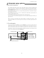
Note: You may have noticed that some option numbers are skipped in the display. Those
skipped item numbers are reserved for special use and they do not affect regular operation of
this printer.
❏ To set this option
By pressing and holding the SETUP key when the RESET key is pressed, the printer enters the
extended setup options, where various functions including the basic setup options can be set.
The keys and operation method in the extended setup options are the same as those in the basic
setup options. However, when exiting from the extended setup options, the initialization of the
printer will be conducted by printing the RESET key.
Select menu
Exit setup to offline
Select function
TOF SET
EXTENDED SETUP
RESET
PARK
QUALITY
BIN
EXIT
ENTER
SETUP
ALT
Store selected function
Enter extended setup options
33
M.LF
LF
FF
M.RLF
RLF
TEAR OFF
POWER
ON LINE
P.OUT
ON LINE
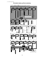
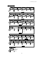
5. Extended setup options
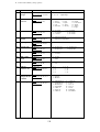
Extended setup options summary
Press both the SETUP and RESET keys to enter the extended setup options.
●Basic setup options #1-#8
●Extended setup options #1-#87
1
2
3
4
MULTIPART
PAGE LENGTH
(FANFOLD)
PAGE LENGTH
(SINGLE)
FONT SELECT
NORMAL *
DARK 1
DARK 2
2
2.5
3
3.5
4
4.5
5
5.5
6
6.5
7
7.5
8
8.5
9
9.5
11
SELECT SETUP
MEMORY
EMULATION MODE
EPSON *
IBM
HP
EMULATION MODE
ROMAN-8 *
CODE PG
PC-8D/N
ECMA
LEGAL
CHARA.TABLE
ITALIC *
GRAPHICS
DOWNLOAD
CODE PAGE
13
CHARACTER
TABLE (IBM)
CHARA. TABLE
CHAR.SET1 *
CHAR.SET2
66
79
83
91
100
116
120
141
200
400
600
800
1000
1200
1400
1600
The asterisk (*) indicates
the factory default setting.
CHARACTER
TABLE (HP)
MEMO 1
MEMO 2
MEMO 3
FACTORY
ZOOM IN/OUT
10 CPI *
12 CPI
15 CPI
16.7CPI
17.1CPI
20 CPI
24 CPI
PROPORTIONAL
1/2 PROPORTIONAL
10
0 ≤ n ≤ 480
Default: n=14
CHARACTER
TABLE (EPSON)
ROMAN *
SANS SERIF
COURIER
PRESTIGE
SCRIPT
OCR-B
OCR-A
GOTHIC
ORATOR
ORATOR-S
EMULATION
TOP OF FORM
+ n/60 inches
12
CHARACTER
PITCH
8
7
TOF
ADJUSTMENT
B5 PORT
B5 LAND
A4 PORT *
A4 LAND
B4 PORT
B4 LAND
LETTER PORT
LETTER LAND
LEGAL PORT
LEGAL LAND
A3 PORT
A3 LAND
10
10.5
11*
11.5
12
12.5
13
13.5
14
14.5
15
15.5
16
16.5
6
5
SWEDEN1
SWEDEN2
SPAIN
FRANCE
GERMAN
U.K.
PORTUGAL
NORWAY1
NORWAY2
15
14
NATIONAL
FONT
SPAIN
JAPAN
NORWAY
DENMARK2SPAIN 2
LATIN AMERICA
KOREA
TURKEY
LEGAL
IRV
ITALY
FRANC2
GERMAN2
SPAIN2
SPAIN3
JAPAN
PORTUGAL2
16
CODE PAGE
NATIONAL FONT
USA *
FRANCE
GERMANY
U.K.
DENMARK
SWEDEN
ITALY
%
%
%
%
%*
%
%
%
%
%
%
%
%
%
%
%
AGM
(IBM)
CODE PAGE
437:USA *
850:MULTILINGUAL
857:TURKEY
858
860:PORTUGAL
861
ALTERNATE GRAPHIC
NO *
YES
863:CANADIAN-FRENCH
865:NORWAY
BRASCII
ABICOMP
ISO-8859-1
17
18
19
20
21
22
CR SETTING
LF SETTING
LF PITCH
ZERO STYLE
TABULATION
PAGE LENGTH
LOCK
CR SETTING
CR ONLY *
CR+LF
AUTOFEED
LF SETTING
LF ONLY
LF+CR *
PITCH
6 LPI *
8 LPI
9 LPI
3 LPI
4 LPI
ZERO STYLE
NO-SLASHED *
SLASHED
25
26
FONT LOCK
PITCH LOCK
QUALITY LOCK
QUALITY TYPE
FONT LOCK
LQ *
NO *
NLQ
YES
HQDR
DRAFT
S.D
S.S.D.
PITCH LOCK
NO *
YES
24
23
QUALITY
29
BARCODE
SIZE
1*
1.5
2
2.5
QUALITY LOCK
NO *
YES
30
31
32
ENLARGED CHAR
SIZE
GRAPHIC PRINT
MODE
ACCENT CHAR
1
2
4
8*
12
16
24
32
PRINT SPEED
MODE1
MODE2*
MODE3
34
TABULATION
2 CHAR.
4 CHAR.
6 CHAR.
8 CHAR.*
10 CHAR.
12 CHAR.
27
BARCODE/
ENLARGED
CHARACTER
BC/L.CHR
IGNORED
MODE1 *
MODE2
EAN13
UPC-A
UPC-E
POSTNET
ELEMENT
PAGE LOCK
NO *
YES
28
BARCODE
TYPE
BARCODE TYPE
INDSTRIAL 20F5
INTERLEAVED 20F5
MATRIX 20F5
CODABAR
CODE11
CODE39*
CODE93
CODE128
EAN8
PRINT METHOD
SIMPLE*
COMPO
Next page
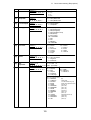
5. Extended setup options
Previous page
33
FF CODE
AT TOF
VALID
YES*
NO
43
RIGHT MARGIN
RIGHT MARGIN
+ n COLUMN
0 n 63
DEFAULT: n=0
49
CSF OPTIONS
CSF TYPE
NOT INSTALLED *
SINGLE
DOUBLE
63
38
34
PCL MODE
PCL MODE
PCL3+ *
PCL3
PCL3+D
44
FANFOLD
PAPER WIDTH
WIDTH
15 INCH *
10 INCH
5 INCH
40
36
CHR TB2 HP
TOP MARGIN
2ND CHARACTER TABLE
45
AUTO SCROLL
AUTO SCROLL
VALID POSITION
LF SPEED
64
STOP BIT
LENGTH
8 BITS *
7 BITS
STOP BIT
1 BIT *
2 BITS
70
LF SPEED
NORMAL*
1/2
80
81
82
PRINT
DIRECTION
DISPLAY
LANGUAGE
INVERT
DISPLAY MODE
DIRECTION
PRE-DIRECTION
UNI-DIRECTION
BI-DIRECTION *
86
SAVE SETUP
SAVE
MEMO 1
MEMO 2
MEMO 3
LCD LANGUAGE
ENGLISH *
DEUTSCH
FRANCAIS
ESPANOL
ITALIANO
LEFT MARGIN
+ n COLUMN
0 n 63
DEFAULT: n=0
48
LABEL MODE
NO *
YES
DETECTION
ANY POS*
PAGE END
60
61
62
INTERFACE
SELECT IN
CMD
PARITY BIT
INTERFACE
PARALLEL*
SERIAL
AUTO
66
BAUD
RATE
BAUD RATE
38400 BPS
19200 BPS
9600 BPS *
4800 BPS
2400 BPS
1200 BPS
600 BPS
300 BPS
72
BUSY /ACK
TIMING
BUFFER SIZE
BUFFER
64KB *
8KB
128B
BOTTOM MARGIN
+ n LINE
0 n 15
DEFAULT: n=0
OVERRIDE
NO
YES *
71
DSR SIGNAL
NO *
YES
LEFT MARGIN
P.OUT
DETECTION
PROTOCOL
DTR *
XON/XOFF 1
XON/XOFF 2
ETX/ACK
CD SIGNAL
NO *
YES
BOTTOM MARGIN
LABEL MODE
PROTOCOL
DSR ENABLE
42
OVERRIDE BM
65
CD ENABLE
41
37
47
46
AUTO SCROLL
NO SCROLL *
0.5 SEC
1 SEC
5 SEC
10 SEC
15 SEC
51
ANY POS *
TOF ONLY
TOP MARGIN
+ n LINE
0 n 15
DEFAULT: n=0
LINE DRAW *
MATH-7
50
DATA LENGTH
69
35
39
TIMING
TYPE 1
TYPE 2 *
TYPE 3
87
SETUP MENU
LIST
LIST
MAIN *
EXTENDED
ALL SETUP
FACTORY
35
PARITY
NONE *
EVEN
ODD
67
68
SERIAL ERROR
CTS ENABLE
ERROR
PRINT *
IGNORED
73
DATA LATCH
TIMING
STROBE
TYPE F.*
TYPE R.
CTS SIGNAL
NO *
YES
74
ERROR
STATUS
STATUS SIGNAL
YES*
NO
83
84
85
SOFT WARE
SETUP
RESET KEY
LOCK
SLEEP MODE
SOFTWARE
COMMAND
NO
YES *
INVERT
NO *
YES
SELECT IN COMMAND
YES
NO *
I/F
RESET KEY LOCK
NO *
YES
SLEEP
YES*
NO
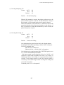
5. Extended setup options (10-13)
Print enhancement
Emulation
The desired emulation mode of the printer can be selected using this function.
10 EMULATION
EML:
EML:
EPSON
IBM
........... Epson LQ-2550 compatible
........... IBM 2391 compatible
36
5. Extended setup options (14-15)
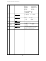
National font style
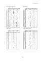
One of the following 16 national fonts can be selected.
14 NATIONAL FONT
23 24
CNTRY:
CNTRY:
CNTRY:
CNTRY:
CNTRY:
CNTRY:
CNTRY:
CNTRY:
CNTRY:
CNTRY:
CNTRY:
CNTRY:
CNTRY:
CNTRY:
CNTRY:
CNTRY:
40
5B
ASCII HEXADECIMAL
5C 5D 5E 60 7B
7C
7D
7E
USA
FRANCE
GERMANY
U.K.
DENMRK
SWEDEN
ITALY
SPAIN
JAPAN
NORWAY
DNMRK 2
SPAIN 2
LATN AM
KOREA
TURKEY
LEGAL
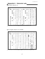
Code page
The default code page can be selected using this function. Refer to the code page table in
Appendix C.
15 CODE
C.P.:
C.P.:
C.P.:
C.P.:
C.P.:
C.P.:
C.P.:
C.P.:
C.P.:
C.P.:
C.T.:
PAGE
437
850
857
858
860
861
863
865
BRASCII
ABICOMP
ISO-1
...........
...........
...........
...........
...........
...........
...........
...........
...........
...........
...........
USA (see page 133)
Multilingual (see page 133)
Turkey (see page 133)
Multilingual Euro symbol(see page 134)
Portugal (see page 134)
Icelandic (see page 134)
Canadian-French (see page 134)
Norway (see page 135)
BRASCII (see page 135)
ABICOMP (see page 135)
ISO-8859-1(see page 135)
38
5. Extended setup options (16-18)
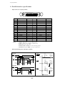
IBM Alternate graphic mode (AGM) (Valid in IBM mode)
This function enables the IBM emulation to work similar to the Epson emulation in high
density graphics. The table below describes the differences in their related control codes.
16 AGM IBM
AGM:
AGM:
NO
YES
Command
AGM: NO
AGM: YES
ESC 3 n
ESC J n
ESC A n
ESC *
Set n/216" line spacing
Line feed n/216"
Set n/72" line spacing
Not supported
Set n/180" line spacing
Line feed n/180"
Set n/60" line spacing
Set various graphic modes
Carriage return (CR)
A carriage return (ASCII code 0Dh or 13) causes data in the buffer to be printed and the
carriage to be moved to the left most print position at the same line. The following option can
be selected when issuing a carriage return. Refer to the specification of your application for
correct selection.
17 CR SETTING
CR:
CR:
CR:
CR ONLY
CR+LF
AT FEED
........... Carriage return without a line feed
........... Carriage return with a line feed
........... Autofeed signal enabled
Note: Autofeed is effective for the system using parallel interface with AUTO FEED signal to
control the the carriage return with or without a line feed. The autofeed signal must be low
when the printer is initialized in order to add a line feed to every CR code.
Line feed (LF)
This function selects whether to execute the carriage return operation when receiving the line
feed command (LF code).
18 LF SETTING
LF:
LF:
LF ONLY
LF+CR
........... Line feed without a carriage return
........... Line feed with a carriage return
39
5. Extended setup options (19-22)
Line feed spacing
This function selects the default line feed spacing. When no line feed spacing is set in the
software command, this value is used as a linefeed.
19 LF PITCH
LF:
LF:
LF:
LF:
LF:
6
8
9
3
4
LPI
LPI
LPI
LPI
LPI
Slashed zero
The zero style is selected as either “0” (no-slash) or “Ø” (slashed).
20 ZERO STYLE
ZERO:
ZERO:
NO-SLSH
SLASHED
........... “0” (no-slash) is selected
........... “Ø” (slashed) is selected
Set default tab stops
The default horizontal tab stops are selected from different tab intervals. This tab setting
becomes effective when the printer receives tab commands from the host system.
21 TABULATION
TAB:
TAB:
TAB:
TAB:
TAB:
TAB:
2
4
6
8
10
12
CHAR
CHAR
CHAR
CHAR
CHAR
CHAR
Lock-in the page length
The page length and the top and bottom margins set on the front control panel are locked-in.
Any page layout related software command cannot override this setting.
22 PAGE
LOCK:
LOCK:
LOCK
YES
NO
40
5. Extended setup options (23-26)
Print quality
The letter or draft quality printing or their variations can be selected. This function performs
the same way as when the QUALITY key is pressed on the front control panel.
This function selects the graphic print speed. See the page 19.
23 QUALITY
QLTY:
QLTY:
QLTY:
QLTY:
QLTY:
QLTY:
LQ
NLQ
HQDR
DRAFT
S.D
S.S.D
........... Letter quality printing
........... Near letter quality printing
........... High quality draft printing
........... Speed draft printing (12cpi)
........... Super speed draft printing (15cpi)
Lock-in the font
The character font set in the "Selecting font style" option on page 28 are locked-in, so any
character font related software command cannot override this setting.
24 FONT
LOCK:
LOCK:
LOCK
YES
NO
Lock-in the character spacing
The character spacing set the "Selecting character spacing" option on page 29 are locked-in, so
any character spacing related software command cannot override this setting.
25 PITCH
LOCK
LOCK:
LOCK:
YES
NO
Lock-in the print quality
The print quality set the "print quality" option on page 41 are locked-in, so any print quality
related software command cannot override this setting.
26 QLTY
LOCK:
LOCK:
LOCK
YES
NO
41
5. Extended setup options (27-28)
Bar code print enhancement
Enable Bar code print and Enlarged character
This function enables the printer to accept the control commands of the barcode and enlarged
character.
27 BC/L. CHR
BC:
BC:
BC:
MODE 1
MODE 2
IGNORED
........... ESC SO and ESC SI can not be used for the bar code data start or stop command.
........... ALL control command are valid.
........... Bar code and Enlarged character are invalid.
Codabar
Bar code type
This function selects a type of bar code.
Bar code type element enables you to
print bar codes by varying the width of the
narrow bar, wide bar, narrow space,
wide bar, or intercharacter gap.
See Appendix B, "Bar code control
code" for details.
CODE 11
CODE 39
28 BC TYPE
*
TYPE:
TYPE:
TYPE:
TYPE:
TYPE:
TYPE:
TYPE:
TYPE:
TYPE:
TYPE:
TYPE:
TYPE:
TYPE:
TYPE:
CODE 93
INDST25
INTRL25
MATRIX
CODABA
CODE11
CODE39
CODE93
C128
EAN-8
EAN-13
UPC-A
UPC-E
POSTNET
ELEMENT
CODE 128
EAN-8
EAN-13
Industrial 2 of 5
UPC-A
Interleaved 2 of 5
UPC-E
Matrix 2 of 5
POSTNET
42
*
5. Extended setup options (28)
Bar code specifications
The table below shows the specifications of thirteen types of bar codes available for the printer. Bar
code printing examples are shown on the previous page.
Bar code
Structure
Industrial 2/5
Interleaved 2/5
5B4S
ICG
Yes
letters (#)
0-9
5B5S
No
0-9
(2 characters
as one unit)
Codabar
4B3S
Yes
0-9,
Special
characters: 24
Matrix 2/5
3B2S
Yes
0-9
Code 11
3B2S
Yes
0-9,"-"
Code 39
5B4S
Yes
Code 93
3B3S
No
Code 128
3B3S
No
EAN-8
2B2S
No
0-9,
AB,...(43)
ASCII
(128)
ASCII
(128)
0-9
EAN-13
2B2S
No
0-9
UPC-A
2B2S
No
0-9
UPC-E
2B2S
No
0-9
Postnet
2LB3SB
No
0-9
Check character
Yes
(Mod 10)
Yes
(Mod 10)
Yes
(Mod 16)
Yes
(Mod 10)
Yes
(Mod 11)
Yes
(Mod 43)
Yes
(Mod 47)
Yes
(Mod 103)
Yes
(Mod 10)
Yes
(Mod 10)
Yes
(Mod 10)
Yes
(Mod 10)
Yes
(Mod 10)
Sample data
1234567
1234567
1234567
Remark
Even number, including
check character. Data
length is variable.
Start and end codes are
sent by the user.
1234567
1234567
Start and end codes are ( )
code. Dual check character
1234567
Start and end codes are
asterisk (*) codes.
Two check characters
1234567
1234567
4912345
491234567890
8 digits (2 prefix code +5
data code+Check character)
13 digits (2 prefix code +10
data code+Check character)
01234500006
12 digits (NSC+10 data+
Check character)
01234500006
UPC-A (12-digit) data is
automatically converted into
UPC-E (10-digit) data.
123456789
6, 10 or 12 digits
(data +Check character)
"B" and "S" in the "Structure" column show the number of bars
and spaces which consist of one or two characters. LB and SB
mean long bar and shot bar, respectively.
43
5. Extended setup options (29-30)
Bar code size
This function specifies the default bar code size.
29 BC SIZE
BC
BC
BC
BC
SIZE:
SIZE:
SIZE:
SIZE:
1
1.5
2
2.5
The tables below show bar code sizes and attributes.
SIZE
1
NARROW BAR
2/120inch
WIDE BAR
6/120inch
NARROW SPACE 2/120inch
WIDE SPACE
6/120inch
INTER CHARA.GAP2/120inch
BAR HEIGHT
8/12inch
HRI PRINT
HRI FONT
CHECK CHARACTERS
PRINT DENSITY
1.5
3/120inch
9/120inch
3/120inch
9/120inch
3/120inch
8/12inch
2
4/120inch
12/120inch
4/120inch
12/120inch
4/120inch
12/12inch
BELOW
OCR-B
Added
1/120 inch
Enlarged character size
This function specifies the default size of enlarged characters.
30 LARGE CH.SIZE
SIZE
SIZE
SIZE
SIZE
SIZE
SIZE
SIZE
SIZE
:
:
:
:
:
:
:
:
1
2
4
8
12
16
24
32
44
2.5
5/120inch
15/120inch
5/120inch
15/120inch
5/120inch
12/12inch
5. Extended setup options (31-33)
Graphic Print Speed
This function selects the print speed of the 120 DPI/240DPI and 180 DPI/360DPI graphics.
31 GR QLTY
QLTY: MODE1
QLTY: MODE2
QLTY: MODE3
MODE1
MODE2
MODE3
120/240DPI
180/360DPI
SPEED Min.Dot pitch SPEED Min.Dot pitch
15.7IPS 1/120"
10.5IPS 1/180"
18.0IPS 1/120"
18.0IPS 1/120"
31.5IPS 1/60"
24IPS
1/60"
Accent character
This function specifies the method of printing accent characters.
32 ACCENT CHR.
PRINT:SIMPLE
PRINT:COMPO
........... The accent character of the resident font is printed.
........... The accent symbol and the character are printed
........... separately to add the accent symbol in the proper position.
Setting of the FF (Form Feed) code at TOF
33 FF CODE / TOF
FF CODE/TOF:YES
FF CODE/TOF:NO
Establish the setting whether or not FF(Form Feed) is to be executed.
When "YES"is set, the FF code performs Form Feed even if the present position is at TOF.
When "NO" is set, the FF code is ignored when the present position is at TOF.
45
5. Extended setup options (40-42)
Paper handling enhancement
Set the top margin
This function sets the top margin by lines with fixed line spacing of 6 lines per inch in the
range between 0 to 15 lines (2.5") from the top of the form.
40 TOP MARGIN
T.M.:
T.M.:
T.M.:
0 LINE
nn LINE
15 LINE
Set the bottom margin
This function sets the bottom margin by lines with fixed line spacing of 6 lines per inch in the
range between 0 to 15 lines (2.5") from the bottom edge of the form.
41 BOTTOM MARGIN
B.M.:
B.M.:
B.M.:
0 LINE
nn LINE
15 LINE
Note
The bottom edge of the form is determined by the page
length or the paper size set by the PAPER key in the
front control panel or in the associated paper size
options in the basic setup options. See the paper size
table on page 27.
Set the left margint
This function sets the left margin by columns with fixed character spacing of 10 characters per
inch in the range between 0 to 63 columns (6.3") from the left-most printable location.
Left most printable location
42 LEFT M.
L.M.:
L.M.:
L.M.:
Left Margin
0 - 63 columns
Left most printable location
Left Margin
0 - 63 columns
0 COL
nn COL
63 COL
Print Area
Print Area
Print Area
47
5. Extended setup options (43-45)
Set the right margin
This function sets the right margin by columns with fixed character spacing of 10 characters
per inch in the range between 0 to 63 columns (6.3") from the right-most printable location.
Right most printable location
43 RIGHT M.
R.M.:
R.M.:
R.M.:
Right Margin
0 - 63 columns
Right most printable location
Right Margin
0 - 63 columns
0 COL
nn COL
63 COL
Print Area
Note
The right edge of the form is
determined by the paper size set
in the front control panel or the
paper width set in the setup
options on page 25 and 26.
Print Area
Print Area
Fanfold paper width
This function sets the paper width to be used in the printer. Depending on the paper width, the
print head will shift to the one half of the print width selected in this function to properly hold
the paper in place, and eliminates the possibility of paper jams during loading.
44 PAPER WIDTH
WIDTH:
WIDTH:
WIDTH:
15 IN
10 IN
5 IN
...........
...........
...........
Maximum printable column at 10 cpi
136 columns
80 columns
36 columns
Autoscroll delay
The Autoscroll function automatically advances the paper to the tear off position when no data
exists in the communication buffer and no new data is received for a period of 0.5, 1, 5, 10, or
15 seconds.
The printer automatically aligns the paper to the top of the next form when data is received.
This feature is very beneficial when it is necessary to print a single invoice, and tear it off
immediately following printing.
45 AUTO SCROLL
NO
SCROLL
SCROLL: 0.5SEC
SCROLL:
1 SEC
SCROLL:
5 SEC
SCROLL: 10 SEC
SCROLL: 15 SEC
Note
Autoscroll becomes invalid when the label protect mode is
set active.
48
5. Extended setup options
Override bottom margin
The effect of this function varies depending whether you are using Cut Sheet or Fanfold paper.
The operation of this function is also varied depending upon the Emulation setting.
46 OVERRIDE BM
OVERRIDE: NO
OVERRIDE: YES
When using Cut Sheet paper, the bottom
margin is set 17 mm from the bottom of
the page. The bottom margin setting can
be overridden by this function, however,
there may be some degradation of print
registration in the override print area.
Refer to the sketch and Table shown
below for details of printable area and
number of lines/page as affected by the
setting of this function.
When using Fanfold paper, this function
only affects the printer's operation on the
last sheet of paper when a paper out
condition occurs. When remove the
fanfold paper from the tracters, printing
will stop approximately 4 inches from
the bottom edge of the paper. When a
paper out condition occurs you may
either move the Friction Lever to the Cut
Sheet position and remove the form
from the tractors, or you may place the
printer back Online and continue
printing in the override print area.
49
(46)
5. Extended setup options (47-50)
Label mode
(valid only in fanfold setting)
Label mode is designed to prevent continuous forms labels from being peeled from the backing
sheet and becoming jammed in the printer.
47 LABEL MODE
LABEL MD: NO
LABEL MD: YES
........... Set the label protect mode off.
........... Set the label protect mode on.
When the bottom edge of the label is positioned on the round surface of the platen for more
than 10 seconds, the label is automatically repositioned away from the platen. When data is
received by the printer, the labels are automatically positioned to the top of the next available
label before printing begins. This function becomes effective when each label is equally apart
and the same page length (min. 2 inches) is set for a single label.
Setting of "Paper out" detection
48 P.OUT DTCT
DETECT: PAGE END
DETECT: ANY POS
In the "ANY POS" setting, "Paper out" detection is functioning at the any position.
In the case of "PAGE END":
For fanfold paper:
"Paper out" detection functions near the perforation only. After
the detection, the print line feed data are not executed. With this
function the printing format is maintained even after the sheet
change.
For cut sheet paper: "Paper out" detection does not function within the paper size.
The "Paper out" detection functions when the LF is exceeded
over the paper size.
When a sheet shorter than the selection sheet size is printed. the
printing is made even if paper out.
Cut sheet feeder type
A function for defining the CSF configuration. The CSF type, single tray can be set when the CSF is
installed.
When single is selected, the paper tray (bin 1) can be selected by the BIN key on the front control panel.
49 CSF OPTION
NOT INSTALL
CSF:
SINGLE
CSF:
DOUBLE
Setting of the auto-scrolling position
50 SCROLL POS.
SCROLL:ANY POS
SCROLL:TOF ONLY
Set the position for executing auto-scrolling.
In the case of "TOF ONLY" : Auto-scrolling is performed only
when the present position is at TOF .
"ANY POS" : If the perforation is between the paper cutter and
printing head position, auto-scroll is performed at any position
after a prescribed time after the printing.
50
5. Extended setup options (51-62)
Line Feed Speed
This function specifies the line feed speed.
The 1/2 LF speed feeds paper more stably. It is useful for thick paper, labeled sheets and
multipart paper in comtinuous printing.
51 LF SPEED
SPEED: NORMAL
SPEED: 1/2
Communication enhancement
Interface type
This function selects the type of interface; the parallel interface or the serial interface. When
this function is executed, the printer is initialized. See "Connecting the computer" section on
page 12 for correct selection and connection of the interface cable.
60 INTERFACE
I/F:
I/F:
I/F:
PARALLEL
SERIAL
AUTO
........... Parallel and serial interface are switched automatically.
SELECT IN signal (parallel interface)
When “SLCT IN: YES” is selected, the printer accepts the “select” or "deselect” command
codes regardless of the SELECT IN signal from host system.
When “SLCT IN: NO” is selected, the printer ignores the “select” or "deselect” command codes
regardless of the SELECT IN signal from host system.
When “SLCT IN: I/F” is selected, the printer functions according to the SELECT IN signal
from host system.
61 SLCT IN CMD
SLCT CMD: YES
SLCT CMD: NO
SLCT CMD: I/F
Parity bit (serial interface)
This function selects the appropriate parity bit in the transmission data frame.
62 PARITY BIT
PARITY: NON
PARITY: EVEN
PARITY: ODD
51
5. Extended setup options (63-66)
Data length (serial interface)
This function selects the appropriate data length.
63 DATA LENGTH
LENGTH: 8 BITS
LENGTH: 7 BITS
Stop bit (serial interface)
This function selects the appropriate number of stop bits.
64 STOP BIT
STOP BIT: 1 BIT
STOP BIT: 2 BITS
Communication protocol (serial interface)
This function selects the appropriate communication protocol. Refer to the specification of
your host system for selecting proper communication protocol.
65 PROTOCOL
PROT.:
PROT.:
PROT.:
PROT.:
DTR
XON/OF1
XON/OF2
ETX/ACK
........... BUSY/READY protocol
........... Set XON/XOFF 1
........... Set XON/XOFF 2
Note: The difference in XON/XOFF 1 and 2: XON/XOFF 1 protocol sends XON code (11h) to
host system at power-on while XON/XOFF 2 does nothing.
Communication speed (serial interface)
This function selects the appropriate baud rate for the data transmission speed.
66 BAUD RT
SPEED:
SPEED:
SPEED:
SPEED:
SPEED:
SPEED:
SPEED:
SPEED:
38400
19200
9600
4800
2400
1200
600
300
B
B
B
B
B
B
B
B
52
5. Extended setup options (67-70)
Serial error check (serial interface)
This function selects the printer's response to a serial data transmission error. The serial data
transmission error includes a parity error, framing error, and over-run error. If "PRINT" is
enabled, the data in error is printed as an asterisk(*). If "IGNORED" is enabled, the data in
error is discarded.
67 SERIAL ERROR
S.ERROR: PRINT
S.ERROR:IGNORED
CTS signal (serial interface)
This function accepts or ignores the CTS (Clear to Send) signal from the host.
68 CTS ENABLE
CTS:
CTS:
NO
YES
........... Ignores the CTS signal
........... Functions according to the CTS signal from the host
CD signal (serial interface)
This function accepts or ignores the CD (Carrier Detect) signal from the host.
69 CD ENABLE
CD:
CD:
NO
YES
........... Ignores the CD signal
........... Functions according to the CD signal from the host
DSR signal (serial interface)
This function accepts or ignores the DSR (Data Set Ready) signal from the host.
70 DSR ENABLE
DSR:
DSR:
NO
YES
........... Ignores the DSR signal
........... Functions according to the DSR signal from the host
53
5. Extended setup options (71-74)
Communication buffer size
This function selects the maximum size of the input buffer.
When the selection of this function is completed, the printer is initialized.
The buffer size affects the signal protocol in serial data communication. In these protocols the
printer's busy/ready state changes according to the data remaining values in the input buffer
described below.
71 BUFFER SIZE
B.SIZE:
B.SIZE:
B.SIZE:
64 KB
8 KB
128 B
BUFFER
SIZE
Ready to Busy
(CIN)
Busy to Ready
(CRN)
1k byte
3k byte
32 byte
64 byte
64k byte
8k byte
128 byte
Note: When the remaining data capacity of the input buffer is
smaller than CIN, the printer becomes busy. This state continues
until the remaining capacity of the buffer is larger than CRN.
Busy/ACK timing (parallel interface)
This function selects timing to activate the ACK signal for 8µ seconds (type 1) before, 4µ
seconds (type 2) before, or simultaneously synchronized (type 3) with the busy signal going
low.
72 BUSY/ACK
Type
Timing
TYPE 1
TIMING: TYPE 1
TIMING: TYPE 2
TIMING: TIPE 3
BUSY
8 µs
ACK
TYPE 2
BUSY
TYPE 3
BUSY
ACK
ACK
Data latch timing (parallel interface)
This function selects timing to latch the data signals at the rising edge (type R) or falling edge
(type F) of the STROBE signal.
Type
Timing
73 DATA LATCH
TYPE F
LTCH:
LTCH:
STROBE
DATA 1~8
TYPE F.
TYPE R.
STROBE
TYPE R
DATA 1~8
Setting of whether ERROR/PE signals are output or not
Setting is made whether or not ERROR and PE signals for the parallel interface are
output.
When "NO" is selected,
ERROR signal remains HIGH, and PE signal remains LOW, even if Error status.
74 ERROR STATUS
STATUS SIG.:YES
STATUS SIG.:NO
54
5. Extended setup options (80-82)
Miscellaneous
Print direction
This function selects either pre-directional printing, bi-directional printing, or uni-directional
printing. Software commands to control the printing direction will override this selection.
Particular characters such as IBM graphic characters are always printed unidirectional.
80 PRINT DIR
PRINT:
PRINT:
PRINT:
PRE-DIR
UNI-DIR
BI-DIR
........... Defaults to bi-directional printing
• Pre-directional printing:
Whenever a double pass of the print head is required, the direction of the second pass is the
same as that of the first pass. This logic-seeking, unidirectional printing can be used,
therefore, in modes such as double strike and double height printing. The logic seeking
capability is executed before the first pass of the print head. The printing direction of all
passes is the same as that of the first pass.
• Bi-directional printing:
Successive passes of the print head alternate between the left-right and right-left direction.
• Uni-directional printing:
Data is always printed in a single direction from the left to the right.
LCD display language
This function selects the display language for the printer's display window (LCD).
81 DISPLAY LANG
LANG:
LANG:
LANG:
LANG:
LANG:
ENGLISH
DEUTSCH
FRANCAIS
ESPANOL
ITALIANO
...........
...........
...........
...........
...........
English
Germany
French
Spanish
Italian
Invert LCD display
This function sets up-side down text display in the LCD. Use with the reverse control panel
sheet. (See page 136)
82 INVERT DISP
INVERT:
INVERT:
NO
YES
55
5. Extended setup options (83-87)
Software controlled setup
This function enables/disables the special software commands that are designed to control most
of the extended setup options from host. See "Printer setup command codes" section in
Appendix B.
83 SOFTWARE SET
SOFTWARE: NO
SOFTWARE: YES
Lock the RESET key
This function locks up the RESET key during the online mode in order to avoid an accidental
reset during printing.
84 RESET LOCK
LOCK:
LOCK:
NO
YES
Setting ENERGY STAR
Set the power conservation standby mode.
When this mode is valid, if the standby mode continues about 14 minutes after printing, the
power conservation mode is engaged. Switching to the normal mode is effected when any print
action is performed.
85 SLEEP MODE
SLEEP MODE:YES
SLEEP MODE:NO
Saving user setup options
This function saves the current setup into one of three memory areas.
Press the ENTER key to store the current setup in the desired memory area. This does not
affect the current setting. See "Loading user setup option" for the preprogrammed setups.
86 SAVE SETUP
SAVE:
SAVE:
SAVE:
MEMO 1
MEMO 2
MEMO 3
Printing list of setting options
This function prints the list of the current basic setup options, extended setup options, factory
setup contents, or all the setups in the memory areas.
Press the ENTER key to start the selected item listing. This does not affect the current setting.
87 SETUP LISTING
LIST:
LIST:
LIST:
LIST:
MAIN
EXTEND
ALL SET
FACTORY
...........
...........
...........
...........
Lists
Lists
Lists
Lists
current basic setup options
current extended setup options
all setup listings including user setups
factory setup contents
56
6. Setting the application software
6. SETTING THE APPLICATION SOFTWARE
About printer driver
Printer Driver is a section of your software that automatically translates instructions from the
software to your printer.
For example, when using some application software if you want to boldface or underline a
word, the printer driver automatically translates your specific boldface or underline instruction
on your application software to printer control command.
Different printers use different control codes for designating print styles. Therefore, it is
important that when you install your software, you select the appropriate printer driver
designed for your printer.
When WINDOWS 3.1, WINDOWS NT 3.51, 4.0, or WINDOWS 95, 98 is used, please install
the Printer Driver attached to this printer.
When this printer is used in the MS-DOS or other environment, such as UNIX or OS/2, proceed
as follows.
Printer driver selection
Select a suitable printer driver from the list of supported printers. This would include either
the Epson LQ-2550 or IBM 2391. Each of these printer drivers should allow you to access
many of the features on your printer.
If this printer is not listed, look for the following printer drivers. While this should allow you
to print your document with your printer, it probably will not allow you to access many features
of the printer. A few of the choices you may see are given below in order of preferences.
Epson
LQ-2500/2550
LQ-1050/1000
IBM
2390/2391
Proprinter XL24E
Proprinter XL24
Notes:
1. Set the emulation type in the extension setup options according to the selection of printer
driver. For example, when you select the Epson LQ-2550 printer driver, you should set the
emulation type to the Epson mode.
57
7. Troubleshooting
7. Troubleshooting
If an error occurs during printing, you will get several warnings. A buzzer sounds, P.OUT
lamp blinks, and an error message appears in the display window of the front control panel.
❏ Error Messages
Error Message
Cause and Solution
CARRIAGE ERROR
The printer cannot detect the print head position.
◆ Turn off the printer immediately. After a brief wait, turn on
the printer again.
RAM ERROR
(NO LCD DISPLAY
The P.OUT lamp blinks and the
buzzer sounds after power on. )
Internal RAM does not function properly.
◆ Turn the printer off and back on again. If the error persists,
consult your dealer.
FAN ERROR
Abnormal fan operation is detected.
HEAD PROTECTION
(ON LINE lamp blinks.)
Long continuous printing may overheat the print head.
◆ The printer stops temporarily and restarts automatically
when the print head temperature lowers to a safe level.
PAPER ERROR
(Buzzer sounds 3 times.)
Paper jam or improper paper operation has occurred.
◆ If paper parking is not completed, press the PARK key.
Otherwise reload the paper.
PAPER OUT
Paper is not loaded in the printer.
◆ Load paper (pages 13 and 14).
COVER OPEN
One of the printer covers is open.
◆ Close the cover to restart the operation.
POWER DOWN
Abnormal current is detected.
◆ The printer is automatically turn off. Stop using the printer,
and contact the dealer.
60
7. Troubleshooting
❏ Troubleshooting guide
Problem
Cause and Solution
POWER lamp fails to light
◆
◆
Power cord not connected.
Blown fuse in the printer.
Printer stops or slows
down on printing
◆
Print head has overheated. Wait until it has cooled down.
P.OUT lamp lights
incorrectly
◆
◆
Paper detect sensor may be damaged.
Sensor hole is clogged.
Poor quality printing or
smudging of the paper
◆
◆
◆
Old or worn out ink ribbon needs to be replaced.
Head adjustment lever is not set correctly.
Head may need to be cleaned or replaced.
Some characters miss
printing
◆
Ribbon cassette is not properly installed.
Incorrect character
printed
◆
Host system control and data code may not match the
printer's setup.
Paper not advancing
◆
Incorrect paper select lever setting.
Fanfold paper slips
◆
Stack of fanfold paper behind the printer is placed
crookedly.
The paper select lever is in the single sheet setting.
◆
Extra line feed
◆
The automatic carriage return option in the extended setup
options is set incorrectly.
Paper jam
◆
◆
Paper is curled.
Move the paper select lever to the continuous paper setting
and carefully remove the jammed paper.
Paper Bail abnormal
operation
◆
Turn off the printer and wait one minute, and then turn it
back on again. Consult your dealer if the error persists.
61
7. Troubleshooting
❏ Input Hexadecimal Dump Mode
The Input hexadecimal dump capability of the printer enables monitoring of data as it is sent to
the printer. Each Escape Sequence, Control Code, and ASCII character sent from the computer
to the printer is printed in a two-digit hexadecimal format. Such printing is initiated after 16
bytes of data have been transmitted to the printer. Hexadecimal values and their corresponding
ASCII characters between the values 20h to 7Eh are printed on each line.
TOF SET
HEX DUMP
LQ
RESET
PARK
BIN
QUALITY
EXIT
ENTER
SETUP
ALT
M.LF
LF
FF
M.RLF
RLF
TEAR OFF
POWER
ON LINE
P.OUT
ON LINE
To run this mode in draft printing
Press the FF key while turning ON the printer or pressing the RESET key. Hold down the FF
key until the LCD displays "HEX DUMP DRAFT"
To run this mode in LQ printing
Press the FF and ON LINE keys simultaneously while turning ON the printer or pressing the
RESET key. Hold down the both FF and ON LINE keys until the LCD displays "HEX DUMP
LQ"
To terminate this mode
Press the RESET key or turn off the power.
Example
10
20
30
40
50
60
70
00000
00010
REM HEXADECIMAL DUMP LIST EXAMPLE
OPEN "LPT1:"AS #1
WIDTH #1,255
PRINT #1,"ABC";CHR$(13);CHR$(10);
PRINT #1,"123";CHR$(13);CHR$(10);
PRINT #1,"HENRY IS HANDSOME"
END
41 42 43 0D 0A 31 32 33
49 53 20 48 41 4E 44 53
0D 0A 48 45 4E 52 59 20
4F 4D 45 0D
ABC..123..HENRY
IS HANDSOME.
ASCII characters are printed according to hexadecimal codes of the data. Codes other than
1Bh and 20h to 7Eh are printed as “.” (2Eh). For the code 1Bh, “IE” is printed in draft mode
and “ ESC” is printed in LQ mode.
During the Hexadecimal mode, the SETUP, and QUALITY keys are disabled.
62
8. Maintenance
8. Maintenance
❏ Cleaning
Minimum periodical cleaning will ensure the maximum performance from your printer. Do not
spill or splash cleaning liquid inside the printer. Please refer to the "Printer cover removal" on
page 64 to remove the covers for cleaning.
Before cleaning the printer, be sure to turn off the power and disconnect the power cord.
Power may be required to clean the platen.
◆
Platen
Use a platen cleaner, or any weak alcohol solvents, to remove any
ink from the platen and bail rollers. Do not apply any other liquid
chemical to the platen.
Even with a specified platen cleaner, frequent use of the liquid
is not recommended. Apply only when it is necessary.
Inside the printer
◆
Use a vacuum cleaner to remove paper dust and particles inside the
printer. A small brush is suitable for removing paper dust from
hard-to-get-at areas.
Exterior Casings
◆
Clean with a soft cloth dampened with a mild detergent. Never
use organic solvents such as alcohol or thinner.
FPC cable plastic binder
Make sure that the binder clamps the cable securely.
Exterior Casings
Clean with a soft cloth dampened
with a mild detergent.
Inside the printer
Thoroughly vacuum these areas.
Remove any collected paper dust and particles.
63
8. Maintenance (Lubrication)
❏ Lubrication
In the case of heavy use of the printer, apply a specified lubricating oil only to the front and
rear metal carriage bar. When applying the lubricant to the carriage bars, spread the oil by
manually moving the print head back and forth along the carriage bar.
Consult your dealer to obtain the recommended lubricating oil. Do not use an unspecified oil,
or it may reduce the printer's performance drastically.
Oiling
Clean thorougly with a dry cloth,
then apply specific type of lubricants:
Cosmo Hydro (HV#22) recommended.
Rear bar
Front bar
❏ Printer cover removal
Rear Top Cover Removal
◆
◆
Stopper
Stopper
64
◆
Remove the Rear Cover.
Open the Rear Cover to the level
position and pull it.
Remove the two stoppers for the Rear
Top Cover.
Detach the two screws to remove the
two Stoppers.
Remove the Rear Top Cover.
Slide the Rear Top Cover toward the
rear and raise it to vertical position and
lift straight upward.
8. Maintenance (Printer cover removal)
Printer Cover
Guide
◆
Open the front cover to an upright
position, then lift and remove the
cover.
Pivot
Rear Cover
◆
Open the rear cover from the
bottom edge of the cover and pull it
away from the printer to remove.
Paper Rack
◆
Slide both paper guides to the
extreme left and right edges of the
paper rack. Raise the rear end to
stand vertically and lift straight
upward to remove.
Sound Seal Cover
◆
L-angle Hinge
65
Push out on the outer edge of the
sound seal cover where it connects
to the L-angle from the printer
while pushing the stud of the Langle out of the hole. Then remove
the whole cover.
8. Maintenance (Vertical alignment mode)
❏ Vertical alignment mode
The vertical alignment mode serves to compensate for the slippage of the vertical printing
positions, that occurs due to individual differences and age distortion of the printer.
This mode has two features: print start alignment as A-MODE and bidirectional print alignment
as B-MODE. The print start adjustment aligns the print position of two different print modes at
the left margin. While the bidirectional print adjustment aligns the vertical dot mis-positioning
within one print mode in bidirectional printing. Because of their correlation, always set the
bidirectional alignment after the print start adjustment.
The print mode used for these adjustments is categorized as 11 and 12 groups (A-MODE 1 to
11, B-MODE 0 to 11) that differ in printing speed. By aligning characters with the typical
character mode of each group, the character modes within the group are automatically adjusted,
e.g. Draft pica printing mode belongs to MODE 0 group.
Operation and printing pattern
Before performing the adjustment mode, make sure that the ribbon cassette and at least 10-inch
wide paper are properly installed in the printer.
Select mode No.
Exit alignment mode
Select pattern No.
POWER
ON LINE
P.OUT
TOF SET
PARK
BIN
QUALITY
EXIT
ENTER
SETUP
ALT
ALIGN ADJUST
RESET
Enter alignment mode
M.LF
LF
FF
M.RLF
RLF
TEAR OFF
ON LINE
Set printing conditions
1 Press the SETUP and ALT keys simultaneously while turning ON the printer or pressing the
RESET key. Hold down the both SETUP and ALT keys until the LCD displays "ALIGN
ADJUST".
SETUP + ALT + RESET or Power ON
key
ALIGN. ADJUST
MENU indication
A: START POS ADJ
B:
VERT. ADJ
2 Press the left or right arrow key to select A-MODE for print start adjustment or B-MODE for
bidirectional print adjustment. Then press the ENTER key to enter. The operation on either
alignments is done in the same manner. Always select B-MODE after A-MODE is set or has
been set correctly.
66
8. Maintenance (Vertical alignment mode)
3 13 patterns from 0 to 12 are printed in accordance with the printing conditions. The pattern of
the present printing condition is indicated with asterisks (*).
PRINTED PATTERNS EXAMPLE
Description of Patterns
• A pattern describes the type of printing conditions for each mode.
• A number with “*” in the printing example represents the printing condition
being set at present.
• The dots pattern ("" "" ")
" indicates the printing condition in between the adjacent
patterns, the setting is valid.
4 Make sure, the vertical alignment of the chosen print pattern which is marked with "*" is the
best aligned among the 0-12 patterns.
If not the best, you may change to the best aligned one among 0-12.
67
8. Maintenance (Vertical alignment mode)
A-MODE 1: NO. 6
LCD Description
Pattern No. (0-12)
Mode No. (1-11or 0-11)
Key Operation
Up and down arrow keys
Left and right arrow keys
EXAMPLE (To change the pattern No. 6 to 7 in A-MODE 4.)
A-MODE 3
0
>---->
>---->
HHH
HHH
1
2
3
4
5
6
*
7
8
9
10
11
12
HHH HHH HHH HHH HHH HHH HHH HHH HHH HHH HHH HHH
HHH HHH HHH HHH HHH HHH HHH HHH HHH HHH HHH HHH
Best aligned is chosen
A-MODE 4
0
>---->
>---->
1
2
3
4
5
6
*
7
8
9
10
11
12
HHH HHH HHH HHH HHH HHH HHH HHH HHH HHH HHH HHH HHH
HHH HHH HHH HHH HHH HHH HHH HHH HHH HHH HHH HHH HHH
Best aligned
Bad aligned is chosen
5 Pressing the Left and Right arrow key changes the Mode number
between 1 to 11 to select the best pattern within the mode.
A-MODE 3: NO.6
PARK
QUALITY
A-MODE 4: NO.6
6 Pressing the Up and Down arrow key changes the pattern number
between 0 to 12 to select the best pattern within the mode.
A-MODE 4: NO.6
M.LF
M.RLF
A-MODE 4: NO.7
7 By scrolling to the desired pattern number and pressing the ENTER key, the selected printing
condition is set. When the condition is set, the corrected pattern of the selected print mode is
printed out.
8 Repeat the steps 5 through 7 until the start position adjustment is completed.
9 Pressing the EXIT key to exit from the start position adjustment (A-MODE). The bidirectional
printing adjustment (B-MODE) takes place automatically and the LCD indicates "B: VERT
ADJ".
10 Press the ENTER key to enter the bidirectional printing adjustment (B-MODE).
11 Repeat the steps 5 through 7 until the bidirectional printing adjustment is completed.
12 After all adjustments are completed, press the EXIT key, then the LCD indicates "PRESS
RESET SW". By pressing the RESET key, the printer exits from this vertical alignment mode.
68
9. Bar code and enlarged character
9. Bar code and enlarged character
The printer can print bar codes and enlarged characters.
To activate the bar code and enlarged character function, set #27 BARCODE/ENLARGED CHAR to
MODE 1 or MODE 2 in the EXTENDED SETUP MODE.
This function is applicable to the EPSON or IBM or HP mode. This section describes the outline and
details of the bar code and enlarged character function.
❏ Outline of bar code function
The printer has 14 types of bar codes.
Software commands and options #27 to #29 on the EXTENDED SETUP MODE are used to print bar codes
and enlarged characters.
The software commands are unique to the printer. See the following pages for details of these commands.
1. Industrial 2 of 5
2. Interleaved 2 of 5
3. Matrix 2 of 5
4. Codabar
5. Code 11
6. Code 39
7. Code 93
8. Code 128
9. EAN-8
10. EAN-13
11. UPC-A
12. UPC-E
13. Postnet
14. Element (Created in elements.)
❏ Makeup of bar code
(Example) CODABAR
ICG
Check STOP
Character Character
ICG
START
Character
DATA
HRI
Margin
Start Character :
DATA :
Check Character :
Stop Character :
HRI :
ICG :
Margin :
Barcode
Margin
Initial character of data
Alphanumeric data
Character for check errors in read data
Last character of data
Human Readable Interpretation
Gap between characters (Inter Character Gap)
Data-free portions must be provided on both sides.
Each data-free portion must be approximately ten
times as wide as the narrow space (NS).
69
9. Bar code and enlarged character
(Example) CODABAR
Inter Character Gap
Wide Space
Narrow Space
START
Character
STOP
Character
Wide Bar
Barcode Height
Bar Code function
Check Character
Narrow Bar
HRI
❏ Bar Code command
Function
(1)
DC4
DC4
T
Command
1.
2.
3.
4.
5.
6.
7.
8.
9.
10.
11.
12.
13.
14.
Bar code type
Element width
Bar code height
Setting HRI on and off
HRI font
Check character
Starting the bar code data sequence
Ending the bar code data seqence
Bar code data sequence
Printing density
Guard bar expansion
Start and stop characters
Bar code rotational angle
Disabling HRI of the start and stop characters
DC4
DC4
DC4
DC4
DC4
DC4
ESC
ESC
DC4
DC4
DC4
DC4
DC4
DC4
15.
Value input mode
DC4 DC4 V
16.
Initializing the bar code mode
DC4 DC4 @
Bar code type:
Format: ASCII
Hex
Decimal
DC4
14
20
DC4
14
20
T
54
84
DC4
DC4
DC4
DC4
DC4
DC4
SI
SO
DC4
DC4
DC4
DC4
DC4
DC4
T
E
H
I
F
C
B
D
G
N
R
S
n
n
n
Function: Specifies the bar code type
n = 0 Industrial 2 of 5
7 Code128
1 Interleaved 2 of 5
8 EAN-8
2 Matrix 2 of 5
9 EAN-13
3 Codabar
10 UPC-A
4 Code11
11 UPC-E
5 Code39
12 Postnet
6 Code93
255 Element Print
Parameter 255 (Element print) is used to print a bar code which is input element by element. It can print a bar
code which is not supported by the printer and is represented by combining elements. Since data is input by
elements, HRI printing is not performed and no check digit is added to the bar code. The start and stop
characters is also not added.
70
9. Bar code and enlarged character
(2) Element width: DC4 DC4 E
Format:
ASCII
Hex
Decimal
DC4 DC4
14
14
20
20
E
45
69
n1 n2
n1 n2
n1 n2
Function:
Specifies the n2/120” or n2/180” width of the element n1.
(1 ≤ n2 ≤ 127)
120” or 180” is specified with the DC4 DC4 D command.
n1 = 0: Narrow bar
3: Wide space
1: Wide bar
4: Inter-character gap
2: Narrow space
The narrow bar width or narrow space is used as the element width for
Code 93, Code 128, EAN-8, EAN-13, UPC-A, and UPC-E.
One element width of bar 1: Narrow bar width
One element width of space 1: Narrow space width
The midium bar or wide space width is used as the midium element
width for Code 11. The wide element width is (wide bar width x 2 narrow bar width).
This setting is not valid for Postnet.
The inter-character gap means the space between each set of codes of a
bar code which begins with a bar and ends with a bar.
(3) Bar code height: DC4 DC4 H
Format: ASCII
Hex
Decimal
DC4
14
20
DC4
14
20
H
48
72
n
n
n
Function: Sets the bar code height to n/12”. (0 ≤ n ≤ 120)
The currently set line feed pitch serves as the bar code height when
is set to 0. This setting is not valid for Postnet.
(4) Setting HRI on and off: DC4 DC4 I
Format: ASCII
Hex
Decimal
DC4
14
20
DC4
14
20
I
49
73
n
n
n
Function: Specifies whether or not to print an HRI. Also specifies the
HRI printing position if an HRI is to be printed.
n = 0: HRI not printed.
1: HRI printed below the bar code symbol.
2: HRI printed above the bar code symbol.
No HRI printed for Postnet or Element regardless of this setting.
71
9. Bar code and enlarged character
(5) HRI font: DC4 DC4 F
Format:
ASCII
Hex
Decimal
DC4
14
20
DC4
14
20
F
46
70
n
n
n
C
43
67
n
n
n
Function: Selects the font of printing the HRI.
n = 0: Currently selected font
1: OCR-A
2: OCR-B
This setting is not valid for Postnet or Element.
(6) Check character: DC4 DC4 C
Format:
ASCII
Hex
Decimal
DC4
14
20
DC4
14
20
Function: Specifies whether to add a check character automatically.
n = 0: No check character is added. (If a check character is needed, the
user must send bar code data.)
1: A check character is added. (The check character is not printed
in the HRI when Code 93 or Code 128 is selected.)
If the Codabar or Element is selected, no check character is added regardless of
this setting.
The following shows the methods of determining the check characters and bar code
types. (For details, see “Calculating the check character” below.)
Modulus 10 Industrial 2 of 5, Interleaved 2 of 5, Matrix 2 of 5, EAN, UPC,
Postnet
Modulus 11 Code 11 (Dual Check character)
Modulus 16 Codabar
Modulus 43 Code 39
Modulus 47 Code 93 (Dual Check character)
Modulus 103 Code 128
(7) Beginning of the bar code data sequence: ESC SI
Format:
ASCII
ESC
Hex
1B
Decimal
27
SI
0F
15
Function: Indicates the beginning of a bar code data sequence.
Data between this and the end command of the bar code data sequence
is regarded as bar code data.
This command is valid only when #27 BARCODE/LABEL MODE is
set to MODE 2 in the EXTENDED SETUP MODE.
72
9. Bar code and enlarged character
(8) End of the bar code data sequence: ESC SO
Format:
ASCII
Hex
Decimal
Function:
SO
0E
14
Indicates the end of a bar code data sequence.
This command is valid only when #27 BARCODE/LABEL MODE is set
to MODE 2 in the EXTENDED SETUP MODE.
(9) Bar code data sequence: DC4 DC4 B
Format:
ASCII
Hex
Decimal
Function:
ESC
1B
27
DC4
14
20
DC4
14
20
B
42
66
n
n
n
d1
d2 ... dk
Specifies the number (“n”) of data to be regarded as bar code data.
00 ≤ n ≤ 68
00 ≤ dk ≤ 255
00 ≤ k ≤ 68
If the Element is selected; 0 ≤ n, dk, k ≤ 255
This comand is valid when #27 BARCODE/LABEL MODE is set to MODE1 or
MODE2 in the EXTENDED SETUP MODE.
(10) Printing density: DC4 DC4 D
Format:
Function:
ASCII
Hex
Decimal
DC4
14
20
DC4
14
20
D
44
68
n
n
n
Specifies the density of printing bar code symbols (in the horizontal
direction).
Specifies the unit of element width.
n = 0:
Bar code symbols are printed at 120 dpi. (Default value)
1:
Bar code symbols are printed at 180 dpi.
If a bar code is rotated by 90 or 270 degrees using the DC4 DC4 R (bar code
rotational angle) command, a bar code is printed at 120 dpi horizontally and 180
dpi vertically.
(11) Guard bar expansion: DC4 DC4 G
Format:
Function:
ASCII
Hex
Decimal
DC4
14
20
DC4
14
20
G
47
71
n
n
n
Specifies whether or not to expand EAN or UPC guard bars.
n = 0: Guard bars are not expanded.
1: Guard bars are expanded. (Default value)
73
9. Bar code and enlarged character
(12) Start and stop characters: DC4 DC4 N
Format:
ASCII
Hex
Decimal
DC4
14
20
DC4
14
20
N
4E
78
n1
n1
n1
n2
n2
n2
Function: Specifies the Codabar start or stop character. n1 selects the
start or stop character. n2 specifies a code of the start or stop
as shown below.
n1 = 0: Start character
1: Stop character
n2 = a, b, c, d, t, n, ✽, or e.
When power is turned on, “a” is selected as the start or stop character.
(13) Bar code rotational angle: DC4 DC4 R
Format:
ASCII
Hex
Decimal
DC4
14
20
DC4
14
20
R
52
82
n
n
n
Function: Specifies the rotational angle of the bar code in units of 90 degrees.
n = 0: 0° (Default value)
1: 90°
2: 180°
3: 270°
(14) Disabling HRI of the start and stop characters: DC4 DC4 S
Format:
ASCII
DC4
DC4
Hex
14
14
Decimal
20
20
Function:
(15) Value input mode: DC4 DC4 V
Format:
Function:
S
53
83
n
n
n
Specifies whether or not to print the start or stop character in the
for Codabar, Code 11, Code 39 or Code 93.
n = 0: The start or stop character is printed in the HRI.
(Default value)
1: The start or stop character is not printed in the HRI.
ASCII
Hex
Decimal
DC4
14
20
DC4
14
20
V
56
86
n
n
n
Specifies whether bar code sequence data is regarded as the normal
character code or a character value when Code 128 is selected.
n = 0: Data is regarded as normal character code. (Default value)
1: Data is regarded as a character value.
If data is regarded as the normal character code, the printer
automatically move the subset or inserts a shift code according to
the data.
74
9. Bar code and enlarged character
(16) Initializing the bar code mode: DC4 DC4 @
Format:
ASCII
Hex
Decimal
DC4
14
20
DC4
14
20
@
40
64
Function: Initializes the bar code mode.
The following show the default settings for bar code.
Bar code type:
SETUP
Narrow bar width:
SETUP
Wide bar width:
SETUP
Narrow space width:
SETUP
Wide space width:
SETUP
Inter- character gap:
SETUP
Bar code height:
SETUP
Setting HRI:
Below the bar code symbol
HRI font
OCR-B
Check character:
Added
Printing density:
1/120”
❏ Data processing in the bar code data sequence
● In a bar code data sequence following ESC SI, any codes
other than the ESC code are regarded as bar code data.
Continuous two-byte ESC codes (ESC + ESC) are
regarded as a one-byte ESC bar code.
● In a barcode data sequence following ESC SI, SO ESC+
SI and ESC + ESC are valid and the other ESC sequence
are ingnored. The ESC code and the following data, two
bytes in all, are discarded.
● When a start or stop character code (e.g., * code of Code
39) is input in a bar code data sequence, the bar code
data sequence stops if bar code data has already been
input in that sequence. The data that was input is valid
(and converted into a bar code). If not, the bar code data
sequence does not stop and the code is discarded.
● When 68 bytes of data is input, the bar code data sequence
ends automatically.
When Code 93 or Code 128 is selected, the bar code data
sequence ends when the amount of input data, including the
automatically inserted control character, reaches 68
75
9. Bar code and enlarged character
❏ Printing bar codes
❏
●
Bar codes are printed at normal LQ 10 cpi (158 cps) print speed when the printing
density is 120 dpi or at Dark 1 LQ 10 cpi (79 cps) print speed when the printing density is
180 dpi. (This does not apply to printing paths involving HRI printing or duty control.)
●
Bar codes and normal characters are printed separately. When the bar code data
sequence start code is processed, print data other than bar code data contained in the
buffer is printed. When print data other than bar code data is input, bar code data
contained in the buffer is printed.
●
Like the right margin overflow processing for character data, data preceding bar code
data is printed and the bar code data is printed from the left margin on the following line
if the data exceeds the right margin.
If bar code data cannot be printed between the left and right margins, the bar code data
is ignored.
●
If the vertical line feed pitch is smaller than the bar code height, reverse feeding is
performed to move to the following printing position. (If an out-of-paper error is detected
in a bar code printing path, the following paths are printed on the following form.)
HRI
●
The HRI is adjusted to the center of the bar code symbol width and printed at 10 cpi
unless EAN or UPC guard bar expansion is executed. If EAN or UPC guard bar
expansion is executed, an HRI is printed at the equal space between the center guard bar
and the left or right guard bar.
If the HRI width is greater than the bar code symbol width, the HRI printing pitch is
reduced to print the HRI in the same width as the bar code symbol width.
●
The HRI is printed below a bar code symbol, the vertical printing position is lower than
the printing start position by (bar code height - 1/6”). If it is printed above the bar code
symbol, the vertical printing position is higher than the printing start position by (1/6” 24/180”).
●
When Code 11 is selected, small triangle ( ) and large triangle ( ) are printed as the
start and stop characters, respectively. (This does not depend on the setting of the check
character.)
●
When Code 93 is selected, white squares ( ) are printed as the start and stop characters,
and a black square ( ) is printed as the control character. A printable character
expressed in combination with the control character is printed as is. (For example, 61H is
printed as ‘a’, not ‘ A’.)
●
When Code 128 is selected, black rhombuses a (◆) are printed instead of non-printable
76
9. Bar code and enlarged character
❏ Error processing
●
If a character code that is not valid for the selected bar code type is input, the character
code is not converted into a bar code symbol but is printed as a character. If the bar code
has a start or stop character added to the HRI, the start or stop character is printed.
‘ ’ is printed instead of an invalid character.
●
If an incorrect number of data are input to form a bar code which should have a specific
number of data, are input data is not converted into a bar code symbol but is printed as is.
●
If incorrect data is input in the UPC-A format and cannot be converted into the UPC-E
format, the input data is not converted into a bar code symbol but is printed as is. (For
the rules of converting the UPC-A format into the UPC-E format, see “UPC-E conversion
rule” below.)
❏ Code 128 subset transition rule
●
The following shows the transition conditions from subset A to subset B.
1. Input a character code unique to subset B (60H to 7FH) when subset A is
selected.
2. Then input a character code unique to subset B (60H to 7FH) without inputting a
character code unique to subset A (00H to 1FH). (If a character code unique to
subset A is input in this step, subset B is not selected. The character code unique
to subset B input in step 1 is expressed with the shift code.)
●
The following shows the transition conditions from subset B to subset A.
1. Input a character code unique to subset A when subset B is selected.
2. Then input a character code unique to subset A without inputting a character
code unique to subset B. (If a character code unique to subset B is input in this
step, subset A is not selected. The character code unique to subset A input in
step 1 is expressed with the shift code.)
●
Subset C is selected when four continuous character codes (30H to 39H) are input.
●
If a code common to subset A and subset B is input when a subset is not determined or
subset C is selected, subset B is selected temporarily selected.
77
9. Bar code and enlarged character
❏ UPC-E conversion rule
●
NSC, manufacturer’s codes (M1 M2 M3 M4 M5), and product item codes (X1 X2 X3 X4
X5) are input data.
1.
2.
NSC must be 0 or 1.
When the manufacturer’s code data is input, the rule is determined and zero
checking of the product item codes is performed.
NZ: Non-zero ✽: 0 to 9
UCP-A Type
Rule 1
Rule 2
Rule 3
Rule 4
3.
M1
✽
✽
✽
✽
M2
✽
✽
✽
✽
M3
✽
✽
3~9
0~2
M4
✽
NZ
0
0
M5
NZ
0
0
0
X1
0
0
0
0
X2
0
0
0
0
X3
0
0
0
✽
X4
0
0
✽
✽
X5
5~9
✽
✽
✽
The following table shows print data if the rule shown above is met.
UCP-E Type
Rule 1
Rule 2
Rule 3
Rule 4
M1
M1
M1
M1
M2
M2
M2
M2
M3
M3
M3
X3
M4
M4
X4
X4
M5
X5
X5
X5
X5 (5~9)
'4'
'3'
M3 (0~2)
❏ Calculating the check character
• Modulus 10
a. The data at the odd-numbered position counted from the right are weighed as 3. The sum of the data
character values is determined.. (The sum is determined without weighing for Postnet.)
b. The remainder of deviding the value determined in step a by 10 is determined.
c. A character having a character value equal to the remainder of subtracting the value determined in
step b from 10 is the check character.
78
9. Bar code and enlarged character
• Modulus 11
a. Data characters are weighed from the right to the left, as, example,1, 2, ..., 10, 1, 2 ... 10, 1,
2 and so forth. The sum of the data character values is determined. (The symbol ‘-’ has a
character value of 10.)
b. A character having a character value equal to the remainder of dividing the value
determined in step a by 11 is the first check character (C).
c. Data characters are weighed from the right to the left, beginning with C, as, for example, 1,
2, ..., 9, 1, 2 ... , 9, 1, 2 and so forth. The sum of the data character values is determined.
d. The character with a character value equal to the remainder of dividing the value determined
in step c by 11 is the second check character (K).
• Modulus 16
a. The sum of the all characters including start and stop characters values is determined. The
following table shows the conversion of character into value.
Value Character Value Character Value Character Value Character
0
4
8
12
16
0
4
8
:
A
1
5
9
13
17
1
5
9
/
B
2
6
10
14
18
2
6
.
C
3
7
11
15
19
3
7
$
+
D
b.
The remainder X of deviding the value determined in step a by 16 is determined. The
remainder Y of subtracting the remainder X from 16 is determined.
c. Convert the remainder Y into the character Z according to the conversion table in a. The
character Z is the check character.
• Modulus 43
a. The sum of the data character values is determined.
b. The character with a character value equal to the remainder of dividing the value
determined in step a by 43 is the check character.
79
9. Bar code and enlarged character
• Modulus 47
a. Data characters are weighed from the right to the left, as, for example, 1, 2, ..., 20, 1, 2 ...
20, 1, 2 and so forth. The sum of the data character values determined..
b. The character with a character value equal to the remainder of dividing the value determined
in step a by 47 is the first check character (C).
c. Data characters are weighed from the right to the left, beginning with C, as, for example, 1,
2, ..., 15, 1, 2 ... , 15, 1, 2 and so forth. The sum of the data character values is determined.
d. The character with a character value equal to the remainder of dividing the value found in
step c by 47 is the second check character (K).
• Modulus 103
a. The sum of the products of the data character values and position values is determined. (The
leftmost character has a position value of 1.)
b. The start character value is added to the sum determined in step a above.
c. The character with a character value equal to the remainder of dividing the value
determined in step c by 103 is the check character.
❏ Other
●
After executing a BS command input immediately after bar code data, printing starts from
the position by one character to the left of the currently set character pitch.
●
When a margin is specified, bar code data in the buffer is cleared.
❏ Element printing
●
The element printing function prints bar codes by inputting data element by element.
●
This function allows the user to print bar codes which are not supported by the printer but
are expressed by combining elements. No HRI is printed, no check digit is added, and a
start or stop character is not added, since data is input element by element.
●
The following show the codes expressing elements.
00H:
Narrow bar
01H:
Wide bar
02H:
Narrow space
03H:
Wide space
04H:
Inter-character gap
80
9. Bar code and enlarged character
❏ Element printing
[Example]
The following shows a BASIC program for printing Code 39 bar codes using the element printing
function. This example shows how to print “CODE39”. (Replace NB, WB, NS and WS in the data
statements in the following example with 0, 1, 2 and 3, respectively.)
100 OPEN "LPT1:" AS #1: WIDTH #1,255
110 DC4$=CHR$ (&H14): ESC$=CHR$(&H1B)
120 SI$=CHR$(&HF):SO$=CHR$(&HE): ICG=4
130 '
140 PRINT #1, DC4$;DC4$;"@";
' Initialize
150 PRINT #1, DC4$;DC4$;"T";CHR$(255); ' Barcode Type: Element Print
160 PRINT #1, DC4$;DC4$;"E";CHR$(0);CHR$(2); ' Narrow Bar: 2/120"
170 PRINT #1, DC4$;DC4$;"E";CHR$(1);CHR$(6); ' Wide Bar: 6/120"
180 PRINT #1, DC4$;DC4$;"E";CHR$(2);CHR$(2); ' Narrow Space: 2/120"
190 PRINT #1, DC4$;DC4$;"E";CHR$(3);CHR$(6); ' Wide Space: 6/120"
200 PRINT #1, DC4$;DC4$;"E";CHR$(4);CHR$(2); ' Inter Char Gap: 2/120"
210 PRINT #1, DC4$;DC4$;"H";CHR$(6);
' Barcode Height: 6/12"
220 '
230 PRINT #1, DC4$;DC4$;"B";CHR$(9*8+7); ' Barcode Data Sequence Start
240 RESTORE 440
250 FOR I=1 TO 9:READ A:PRINT CHR$(A);:NEXT I
260 PRINT #1, CHR$(ICG);
270 FOR J=1 TO 6
280 IF J=1 THEN RESTORE 450
290 IF J=2 THEN RESTORE 460
300 IF J=3 THEN RESTORE 470
310 IF J=4 THEN RESTORE 480
320 IF J=5 THEN RESTORE 490
330 IF J=6 THEN RESTORE 500
340 FOR I=1 TO 9:READ A: PRINT #1, CHR$(A);:NEXT I
350 PRINT #1, CHR$(ICG);
360 NEXT J
370 RESTORE 440
380 FOR I=1 TO 9:READ A: PRINT #1, CHR$(A);:NEXT I
400 PRINT #1,CHR$(13);CHR$(10);
' CR+LF
410 CLOSE #1
420 END
430 '
440 DATA 0, 3, 0, 2, 1, 2, 1, 2, 0
450 DATA 1, 2, 1, 2, 0, 3, 0, 2, 0
460 DATA 1, 2, 0, 2, 1, 2, 0, 3, 0
470 DATA 0, 2, 0, 2, 1, 3, 0, 2, 1
480 DATA 1, 2, 0, 2, 1, 3, 0, 2, 0
490 DATA 1, 2, 1, 3, 0, 2, 0, 2, 0
500 DATA 0, 2, 1, 3, 0, 2, 1 ,2, 0
81
9. Bar code and enlarged character
Enlarged character function
If #27 BARCODE/ENLARGED CHAR is set to MODE 1 or MODE 2 in the EXTENDED SETUP MODE,
enlarged characters can be printed. The enlarged character function is valid for the EPSON or IBM or HP
mode.
❏ Outline of enlarged character function
When the enlarged character mode is selected with the DC4 DC4 l 1 command, any
commands other than those shown below are ignored.
Only three print codes are available: LF, CR and FF. If 521 or more characters of data are
sent without inputting a print command, printing is performed automatically.
❏ Enlarged character command list
Function
Command
1.
Executing backspacing
BS
2.
Executing line feeding
LF
3.
Executing form feeding
FF
4.
Executing carriage return
CR
5.
Initializing the enlarged character mode
DC4 DC4 @
6.
Arrangement of enlarged characters
DC4 DC4 a
7.
Element magnification for enlarged characters
DC4 DC4 c
8.
All-character set for enlarged characters
DC4 DC4 d
9.
Selecting an enlarged character font
DC4 DC4 f
10.
Height expansion for enlarged characters
DC4 DC4 h
11.
HMI for enlarged characters
DC4 DC4 i
12.
VMI for enlarged characters
DC4 DC4 j
13.
Setting and canceling the enlarged character mode
DC4 DC4 l
14.
Enlarged character cell offset
DC4 DC4 o
15.
Enlarged character pitch
DC4 DC4 p
16.
Enlarged character quality
DC4 DC4 q
17.
Enlarged character rotational angle
DC4 DC4 r
18.
Setting and canceling enlarged character smoothing
DC4 DC4 s
19.
Enlarged character top offset
DC4 DC4 t
20.
Setting and canceling underscores for enlarged characters
DC4 DC4 u
21.
Enlarged character width expansion
DC4 DC4 w
22.
Horizontal printing position for enlarged characters
DC4 DC4 x
23.
Vertical printing position for enlarged characters
DC4 DC4 y
82
9. Bar code and enlarged character
(1) Executing backspacing: BS
Format:
Function:
ASCII
Hex
Decimal
BS
08
08
Executes backspacing.
When the BS command is executed, the printing position moves to the
previous character position on the left. The BS command is valid up to
the left margin. A BS command issued on the left margin is ignored.
When a BS command is issued when there is a character on the left with
proportional printing selected, the printer backspaces to that character. If
there is no character or another BS command has just been executed, the
printer backspaces by one space.
(2) Executing line feeding: LF
Format:
Function:
ASCII
Hex
Decimal
LF
0A
10
Executes line feeding.
After printing data, the printer feeds one line by the enlarged character
line feed pitch, which differs depending on whether VMI is valid (by the
DC4 DC4 j command) or not.
VMI valid: Preset VMI amount
VMI not valid: (24 + cell offset)/180” x cell expansion
Line feeding involves a carriage return if the LF SETTING option is set to
LF + CR in the EXTENDED SETUP MODE.
If the bottom margin is specified and the cell size (i.e., 24/180” x cell
expansion) is greater than the printable area in the CSF, cut sheet, or
fanfold paper mode, form feeding is executed and then printing is
executed. If the printing position is at the TOF position, printing is
executed up to the bottom margin without executing form feeding, and
excess data is not printed.
The default pitch is “1/6” x cell expansion”.
83
9. Bar code and enlarged character
(3) Executing form feeding: FF
Format:
Function:
ASCII
Hex
Decimal
FF
0C
12
Executes form feeding.
This command feeds the page to the next TOF position. If there are still enlarged
characters to be printed, they are printed, then form feeding is executed.
(4) Executing carriage return: CR
Format:
Function:
ASCII
Hex
Decimal
CR
0D
13
Executes carriage return.
This command moves the printing position to the left margin without printing any
characters. If the CR SETTING option is set to CR + LF in the EXTENDED
SETUP MODE, a carriage return is executed out after printing.
(5) Initializing the enlarged character mode: DC4 DC4 @
Format:
ASCII
DC4
Hex
14
Decimal
20
Function:
DC4
14
20
@
40
64
Initializes the enlarged character mode.
The following show the default settings for enlarged characters:
Cell expansion:
SETUP expansion
Height expansion:
SETUP expansion
Width expansion:
SETUP expansion
Font:
SETUP font
Character pitch:
10 cpi
HMI:
Invalid
Cell offset:
6/180”
VMI:
Invalid
Character quality:
Standard
Character layout:
Adjusted to the base line
Rotational angle:
0°
Smoothing:
Valid
Top offset:
0/180”
Underscore:
Canceled
Character set:
Enlarged character mode selected
Right and left margins:
Enlarged character mode selected
Page length:
Enlarged character mode selected
Top and bottom margins:
Enlarged character mode selecte
84
9. Bar code and enlarged character
(6) Arrangement of enlarged characters: DC4 DC4 a
Format:
ASCII
Hex
Decimal
DC4
14
20
DC4
14
20
a
61
97
n
n
n
Function: Specifies the standard position for adjusting enlarged
characters in the vertical direction.
n = 00H, 30H: Base line is adjusted to the N’th dot from the top.
(N = 20 x cell expansion)
01H, 31H:
Descender is adjusted to the N’th dot from the top.
(N = 24 x cell expansion)
02H, 32H:
Center is adjusted to the N’th dot from the top.
(N = 12 x cell expansion)
03H, 33H:
Ascender is adjusted to the N’th dot from the top.
(N = 1 x cell expansion)
The MSB of the parameter is masked. Any parameters other than those
shown above are ignored.
The arrangement and position specified here are valid if the enlarged
character rotational angle is not 0 degree. The default setting is n =
00H,30H.
(7) Cell expansion for enlarged characters: DC4 DC4 c
Format:
ASCII
Hex
Decimal
DC4
14
20
DC4
14
20
c
63
99
n
n
n
Function: Specifies cell expansion for enlarged characters.
0 ≤ n ≤ 127
The cell has the size of (24/180” x cell magnification). The MSB of the
parameter is masked.
If n = 0, the expansion specified in the setup mode is selected.
The cell expansion is specified at the beginning of the line. If there is
character data on the line, it becomes valid on the following line.
Enlarged character cell expansion takes priority over the height expansion.
If the height expansion exceeds cell expansion when enlarged character
data is input, the characters are enlarged to the cell expansion value.
The default setting is the expansion specified in the setup mode.
85
9. Bar code and enlarged character
(8) All-character set for enlarged characters: DC4 DC4 d
Format:
ASCII
Hex
Decimal
DC4
14
20
DC4
14
20
d
64
100
n
n
n
d1
d1
d1
d2...dn
d2...dh
d2...dn
Function: Specifies the all-character set for enlarged characters.
1 ≤ n ≤ 255
0 ≤ d ≤ 255
Data with a number specified with the parameter “n” is processed as
character codes. If n = 0, this sequence is ignored.
(9) Selecting an enlarged character font: DC4 DC4 f
Format:
Function:
ASCII
Hex
Decimal
DC4
14
20
DC4
14
20
f
66
102
n
n
n
Specifies the font (typeface) of enlarged characters as shown
below.
n = 0: Roman
1: Sans Serif
2: Courier
3: Prestige
4: Script
5: OCR-B
6: OCR-A
7: Gothic
8: Orator
9: Orator-S
The MSB of the parameter is masked. Any parameters other than those
shown above are ignored.
If the FONT LOCK option is set to YES in the EXTENDED SETUP
MODE, this command is ignored.
The default is the setting selected in the setup mode.
86
9. Bar code and enlarged character
(10) Height expansion for enlarged characters: DC4 DC4 h
Format:
ASCII
Hex
Decimal
DC4
14
20
DC4
14
20
h
68
104
n
n
n
Function: Specifies the height expansion of enlarged characters.
0 ≤ n ≤ 127
The MSB of the parameter is masked.
If n = 0, the expansion specified in the setup mode is selected.
Enlarged character cell expansion takes priority over height expansion. If
the height expansion exceeds the cell expansion when enlarged character
data is input, the characters are enlarged to the cell expansion.
The default setting is the expansion specified in the setup mode.
(11) HMI for enlarged characters: DC4 DC4 i
Format:
ASCII
Hex
Decimal
DC4
14
20
DC4
14
20
i
n1
69
105
n1
n1
n2
n2
n2
Function:
Specifies the HMI (horizontal motion index) of enlarged
characters.
0 ≤ n1 ≤ 255
0 ≤ n2 ≤ 15
The HMI indicates the horizontal distance between two adjacent
characters, i.e., the width the print head moves after printing one
character.
The HMI is (n1 + n2 x 256)/180”.
The high-order four bits of parameter n2 (bit 7 to bit 4) are ignored. The
HMI can be set to zero.
After specifed command have priority over DC4 DC4 p or DC4 DC4 i.
If the PITCH LOCK option is set to YES in the setup mode, this
command is ignored.
The default setting is “10 cpi x widthwise expansion”.
87
9. Bar code and enlarged character
(12) VMI for enlarged characters: DC4 DC4 j
Format:
ASCII
Hex
Decimal
DC4
14
20
DC4
14
20
j
6A
106
n1
n1
n1
n2
n2
n2
Function:
Specifies the VMI (vertical motion index) of enlarged
characters.
0 ≤ n1 ≤ 255
0 ≤ n2 ≤ 127
The VMI indicates the distance between two lines, i.e., the length the print
head moves after printing one line.
The VMI is (n1 + n2 x 256)/180”. The MSB of parameter n2 is masked.
The VMI can be set to zero.
The VMI is not dependent on the length expansion of enlarged characters.
After specifed command have priority over DC4 DC4 j or DC4 DC4 o.
The VMI is invalid and the cell offset 6 line feed pitch is selected (i.e.,
1/6” x cell expansion) by default.
(13) Setting and canceling the enlarged character mode: DC4 DC4 l
Format:
ASCII
Hex
Decimal
DC4
14
20
DC4
14
20
l
6C
108
n
n
n
Function: Sets and cancels the enlarged character mode.
n = 00H, 30H: Cancels the enlarged character mode.
01H, 31H: Sets the enlarged character mode.
The MSB of the parameter is masked. Any sequences other than the
above parameters are ignored.
When the enlarged character mode establish command is issued, the
special effects, character pitch, line feed pitch, length and width doublesize printing settings specified for the emulation become invalid the
enlarged character mode is canceled.
When the enlarged character mode starts, characters are printed in the
conditions selected when the enlarged character mode was last canceled.
If there are non-enlarged characters or bar codes when enlarge character
data is input the non-enlarged character are printed.
In the enlarged character mode, automatic printing is not performed if the
printing position exceeds the right margin. Excess data is abandoned and
the printing position is set at the right margin when the right margin is
exceeded.
If the right margin is exceeded while a single enlarged character is being
printed, the character is printed up to the right margin.
88
9. Bar code and enlarged character
(14) Enlarged character cell offset: DC4 DC4 o
Format:
ASCII
Hex
Decimal
DC4
14
20
DC4
14
20
o
6F
111
n
n
n
Function: Specifies the cell offset for enlarged characters.
0 ≤ n ≤ 255
This command specifies the cell offset for the enlarged characters in
1/180”. The cell offset is used to execute a line feed (LF) command.
In the enlarged character mode, the line is fed by a pitch of (24 + cell
offset)/180” x cell expansion.
The VMI is invalid and the cell offset is 6 by default.
(15) Enlarged character pitch: DC4 DC4 p
Format:
ASCII
Hex
Decimal
DC4
14
20
DC4
14
20
p
70
112
n
n
n
Function: Specifies the pitch of enlarged characters.
n = 00H, 30H: 10 cpi
01H, 31H: 12 cpi
02H, 32H: Proportional
The MSB of the parameter is masked. Any sequences other than the above
parameters are ignored.
If the fixed pitch is selected, enlarged characters have the following width:
10 cpi: (18 x 180”) x widthwise expansion
12 cpi: (15 x 180”) x widthwise expansion
In the proportional mode, proportional characters are expanded by the same
ratio.
When the rotational angle for enlarged characters is set to 90 or 270
degrees, characters other than graphic character are printed at a pitch of
(24/180”) x length expansion. If the PITCH LOCK option is set to YES in
the setup mode, this command is ignored.
The HMI is invalidated and the character pitch is 10 cpi by default.
89
9. Bar code and enlarged character
(16) Enlarged character quality: DC4 DC4 q
Format:
ASCII
Hex
Decimal
DC4
14
20
DC4
14
20
q
71
113
n
n
n
Function: Specifies the quality of enlarged characters as shown below.
n = 00H, 30H: Standard quality
01H, 31H: High-speed 1 quality
02H, 32H: High-speed 2 quality
The MSB of the parameter is masked. Any sequences other than the above
parameters are ignored.
The character quality is specified at the beginning of a line. If there is
character data on the line, this command is reserved and becomes valid on
the following line.
If the QUALITY LOCK option is set to YES in the setup mode, this
command is ignored.
The standard quality is selected by default.
(17) Enlarged character rotational angle: DC4 DC4 r
Format:
ASCII
Hex
Decimal
DC4
14
20
Function:
DC4
14
20
r
72
114
n
n
n
Specifies the rotational angle of enlarged characters as shown
below.
n = 00H, 30H
0°
01H, 31H
90°
02H, 32H
180°
03H, 33H
270°
Enlarged characters are rotated counterclockwise.
The MSB of the parameter is masked. Any sequences other than the above
parameters are ignored.
Printing starts from the position specified with the DC4 DC4 a command
shown above.
Unless the rotational angle is set to 0 degree, no characters are underscored
even when underscores are input.
Pixels are printed at a rotational angle of 0 degree even if the rotational
angle is set to 90, 180, or 270 degrees.
This command is ignored if the PITCH LOCK option is set to YES in the
EXTENDED SETUP MODE and the length and width expansion values of
enlarged characters are different.
The default rotational angle is 0 degree.
90
9. Bar code and enlarged character
(18) Setting and canceling enlarged character smoothing: DC4 DC4 s
Format:
ASCII
DC4
DC4
s
Hex
Decimal
14
20
14
20
73
115
n
n
n
Function: Sets and cancels smoothing of enlarged characters.
n = 00H, 30H: Cancels smoothing.
01H, 31H: Sets smoothing.
The MSB of the parameter is masked. Any sequences other than the
above parameters are ignored.
Smoothing is set by default.
(19) Enlarged character top offset: DC4 DC4 t
Format:
ASCII
Hex
Decimal
DC4
14
20
DC4
14
20
t
74
116
m
m
m
n1
n1
n1
n2
n2
n2
Function: Specifies the top offset of enlarged characters.
m = (20)H
0 ≤ n1 ≤ 255
0 ≤ n1 ≤ 15
The top offset refers to the vertical distance between the top of the cell and
the top of a character. This determines the character position in the cell.
It is specified by (n1 + n2 x 256)/180”.
The high-order four bits of parameter n2 (bit 7 to bit 4) are masked.
The top offset is effective for only one characterafter this sequence.
The top offset is canceled when a line feed (LF) command, form feed (FF)
command, or vertical print position (DC4 DC4 y) command is issued.
The top offset is not dependent on the enlarged character arrangement.
It is always based on the top of the cell (corresponding to the ascenderbased position).
The top offset is not dependent on cell expansion or length expansion.
The bottom of a character (i.e., 24th pin position, regardless of character
type, even for a 30-dot pixel) does not extend beyond the bottom of the
cell. If the top offset is too large and the bottom of the character extends
below the bottom of the cell, the top offset is reduced.
Any sequences other than m = 20H are ignored.
91
9. Bar code and enlarged character
(20) Setting and canceling underscores for enlarged characters: DC4 DC4 u
Format:
ASCII
DC4
DC4
u
n
Hex
14
14
75
n
Decimal
20
20
117
n
Function: Sets and cancels the underscore function.
n = 00H, 30H: Cancels underscoring.
01H, 31H: Specifies the underscoring.
The MSB of the parameter is masked. Any sequences other than the
above parameters are ignored.
An underscore is drawn on the 25th pin line at a thickness of (1 dot x
length expansion of the character).
No underscores are printed if the enlarged character rotational angle is not
set to 0 degree. Underscoring is off by default.
(21) Enlarged character width expansion: DC4 DC4 w
Format:
ASCII
Hex
Decimal
DC4
14
20
DC4
14
20
w
77
119
n
n
n
Function: Specifies the width expansion of enlarged characters.
0 ≤ n ≤ 127
The MSB of the parameter is masked.
If n is set to 0, the magnification specified in the setup mode is selected.
This command is ignored if the PITCH LOCK option is set to YES in the
EXTENDED SETUP MODE.
The expansion specified in the setup mode is set by default.
(22) Horizontal printing position for enlarged characters: DC4 DC4 x
Format:
ASCII
DC4
DC4
x
Hex
Decimal
14
20
14
20
78
120
m
m
m
n1
n1
n1
n2
n2
n2
Function:
Specifies the horizontal position for printing enlarged
characters by (n1 + n2 x 256)/180” as shown below.
m = SP(20)H:
Absolute printing position
-(2D)H: Relative lefthand printing position
+(2B)H:
Relative righthand printing position
0 ≤ n1 ≤ 255
0 ≤ n2 ≤ 15
The MSB of parameter m and the four high-order bits of n2 (bit 7 to bit 4)
are masked.
92
9. Bar code and enlarged character
If parameter m is different than shown above, this sequence is ignored.
The absolute print position is based on the left margin. If the specified
position exceeds the right margin, the print position is located at the right
margin.
If a relative lefthand printing position to the left of the left margin is
specified, left margin becomes the printing position.
If a relative righthand printing position to the right of the right margin is
specified, the right margin becomes the printing position.
The movement distance is not dependent on the width expansion of
enlarged characters.
(23) Vertical printing position for enlarged characters: DC4 DC4 y
Format:
ASCII
Hex
Decimal
DC4
14
20
Function:
DC4
14
20
y
79
121
m
m
m
n1
n1
n1
n2
n2
n2
Specifies the vertical position for printing enlarged characters
by (n1 + n2 x 256)/180” as shown below.
m = SP(20)H:
Absolute printing position
-(2D)H: Relative reverse printing position
+(2B)H:
Relative forward printing position
0 ≤ n1 ≤ 255
0 ≤ n2 ≤ 127
The MSBs of parameters m and n2 are masked. If parameter m is other
than shown above, this sequence is ignored.
The absolute print position is based on the TOF position. If the specified
position extends below the bottom margin, the bottom margin becomes the
print position.
If a relative reverse printing position exceeding the TOF position is
specified, the TOF position becomes the print position.
If a relative forward printing position that extends below the bottom
margin is specified, the print position is located at the bottom margin.
The movement distance is not dependent on the length expansion of
enlarged characters.
93
9. Bar code and enlarged character
❏ Enlarged character print samples
This page shows examples of a BASIC program for printing enlarged
characters and the printed enlarged characters (actual size).
100 OPEN "LPT1:"AS #1
110 DC4$=CHR$(&H14)
120 '
130 PRINT #1, DC4$;DC4$;"@";
' Initializing
140 PRINT #1,DC4$;DC4$;"c";CHR$(8); ' Magnification of cell: x8
150 PRINT #1,DC4$;DC4$;"f";CHR$(4);
' Font typeface: SCRIPT
160 PRINT #1,DC4$;DC4$;"p";CHR$(1); ' Character pitch: 12 CPI
170 PRINT #1,DC4$;DC4$;"l";CHR$(1);
' Magnification mode on
180 '
190 PRINT #1,"8";
' Default size print
200 PRINT #1,DC4$;DC4$;"h";CHR$(2); ' Vertical magnification: x2
210 PRINT #1,DC4$;DC4$;"w";CHR$(2); ' Horizontal magnification: x2
220 PRINT #1,DC4$;DC4$;"a";CHR$(3); ' Alignment: ascender
230 PRINT #1,"ASCE";
240 PRINT #1,DC4$;DC4$;"a";CHR$(2); ' Alignment: center
250 PRINT #1,"CENT";
260 PRINT #1,DC4$;DC4$;"a";CHR$(1); ' Alignment: descender
270 PRINT #1,"DESC";
280 PRINT #1,DC4$;DC4$;"a";CHR$(0); ' Alignment: baseline
290 PRINT #1,"BASE";
300 '
310 PRINT #1,DC4$;DC4$;"w";CHR$(8); ' Horizontal magnification: x8
320 PRINT #1,"H";
330 PRINT #1,DC4$;DC4$;"w";CHR$(1); ' Horizontal magnification: x1
340 FOR N=1 TO 8
350 PRINT #1,DC4$;DC4$;"h";CHR$(N); ' Vertical magnification: xn
360 PRINT #1,RIGHT$;(STR$(N),1); '
370 NEXT N
380 PRINT #1,DC4$;DC4$;"w";CHR$(8); ' Horizontal magnification: x8
390 PRINT #1,DC4$;DC4$;"r";CHR$(1); ' Rotate: 90 degree
400 PRINT #1, "R" ;
410 PRINT #1,CHR$;(13);CHR$(10); ' CR+LF
420 '
430 PRINT #1,DC4$;DC4$;"l";CHR$(0);
' Magnification mode off
440 CLOSE #1
450 END
94
A. Specifications
Appendix A.
Specifications
Printing specifications
Printing method
• Impact dot matrix and bidirectional logic seeking printing
Print Head
• 24 pins, movable-type (parallel/staggered orientation.)
Estimated life expectancy: 500 million dots/wire
Emulation
• Epson LQ-2550
• IBM 2391
Resident fonts
Down load character sets
• Draft, High quality draft, Speed draft, Super speed draft
• Roman, Sans Serif, Courier, Prestige, Script, OCR-B, OCR-A,
Gothic, Orator, Orator-S
• Epson character sets (up to 128 characters downloadable)
• IBM character sets and code pages (32kB download area)
Graphic printing
Bit Image Printing (EPSON/IBM)
11 Categories (8 or 24 pin graphics):
• 60 dpi
• 80 dpi — 8-pin only
• 90 dpi
• 120 dp — 8-pin only
• 120 dpi *
• 180 dpi — 24-pin only
• 240 dpi — 8-pin only *
• 360 dpi — 24-pin only *
• 360 dpi — 48-pin only (IBM mode) *
* Horizontally adjacent dots can not be printed.
Print mode
Character spacings
• 10 cpi Pica print mode
• 12 cpi Elite, Speed draft print mode
• 15 cpi Super speed draft print mode
• 16.7 cpi Condensed print mode
• 17.1 cpi Condensed pica print mode
• 20 cpi Condensed elite print mode
• 24 cpi print mode
• Proportional print mode
• One half proportional print mode
95
A. Specifications
Character Tables
(EPSON mode)
(IBM mode)
Character Tables in the EPSON mode
• Italic character table
• Graphic character table
• Graphic character table, extended
Character Tables in the IBM mode
• IBM character set 1 table
• IBM character set 2 table
• IBM all character set table
International character set
(EPSON mode)
USA, FRANCE, GERMANY, U.K., DENMARK, SWEDEN,
ITALY, SPAIN, JAPAN, NORWAY, DENMARK2, SPAIN2,
LATIN-AMERICAN, KOREA, TURKEY, LEGAL
Codepage Character table
(EPSON, IBM mode)
437(USA), 850(MULTILINGUAL), 857(TURKEY), 858,
860(PORTUGUESE), 861, 863(CANADA-FRENCH), 865
(NORDIC), BRASCII, ABICOMP, ISO-8859-1
Barcode type
(EPSON, IBM mode)
Industrial 2 of 5, Interleaved 2 of 5, Matrix 2 of 5,
Codabar, Code 11, Code 39, Code 93, Code 128, EAN 8,
EAN 13, UPC-A, UPC-E, and Postnet.
Throughput
• Draft (10cpi) :
• HQDR (10cpi) :
• NLQ (10cpi) :
• LQ (10cpi) :
• Speed draft (Elite) :
• Super speed draft :
96
198 lpm
138 lpm
99 lpm
76 lpm
228 lpm
268 lpm
186 lpm
127 lpm
92 lpm
71 lpm
213 lpm
246 lpm
A. Specifications
Evaluation conditions:
Data of 100 lines by 132 columns, all ASCII rolling
pattern characters, and 1/6-inch line feed is input from a
host and is stored in the 64K-byte communication buffer
o f t h e p r i n t e r. Wi t h t h a t c o n d i t i o n , t h e n u m b e r o f
printing lines per minute is measured.
Throughput
Paper feed method
Paper width
Paper weight
Friction method:
• Single cut sheet (A3, B4, A4, B5, letter, legal)
• 55 kg - 90 kg in Japan
• 17 lbs. - 28 lbs. in USA
• 64 g/m 2 - 105 g/m 2 in Europe
Tractor method:
• 45 kg - 90 kg in Japan
• 14 lbs. - 28 lbs. in USA
• 53 g/m 2 - 105 g/m 2 in Europe
CSF mode (option):
• 55 kg - 70 kg in Japan
• 15 lbs. - 21 lbs. in USA
• 60 g/m 2 - 81 g/m 2 in Europe
Label paper
• Paper stiffness of less than 125 kg or equivalent
• Total thickness of less than 0.18 mm
Multiple copies
• Original plus 8, non-carbon, 34 Kg or equivalent
• Total thickness of less than 0.59 mm
Line feed pitch
• Minimum of 1/360 inch
Line feed speed
• 60 lines/second (6 lines/inch)
Print speed
• Super Speed Draft (15 cpi): 846 cps (character per
second)
• Speed Draft (12 cpi):
674 cps
• Draft Pica (10 cpi):
564 cps
• HQDR Pica (10 cpi):
360 cps
• NLQ Pica (10 cpi):
240 cps
• LQ Pica (10 cpi):
180 cps
Recommended
print area
Single sheet Paper
Fanfold Paper
TOF
Print
recommended
area
for single sheets
TOF Adjustment
14/60 inch (6 mm)
Override BM
17 mm
Print
recommended
area
for
continuous form
Perforation
Near perforation
1 inch (25.4 mm)
Final form
13 mm
97
Override BM
4 inches (101.6 mm)
13 mm
A. Specifications
Print mode specifications
Print mode
10 cpi
12 cpi
15 cpi
Draft
16.7 cpi
17 cpi
20 cpi
24 cpi
Proportional
1/2 Proportional
Speed Draft
12 cpi
S.Speed Draft
15 cpi
10 cpi
12 cpi
15 cpi
HQDR
16.7 cpi
17 cpi
20 cpi
24 cpi
Proportional
1/2 Proportional
10 cpi
12 cpi
15 cpi
(EPSON)
15 cpi
(HP/IBM)
Near Letter
Quality
16.7 cpi
17 cpi
20 cpi
24 cpi
(EPSON)
24 cpi
(HP/IBM)
Proportional
1/2 Proportional
Note: (+n) indicates the number of space added.
Multipart
mode
Normal
Dark 1
Dark 2
Normal
Dark 1 & 2
Normal
Dark 1 & 2
Normal
Dark 1 & 2
Normal
Dark 1 & 2
Normal
Dark 1 & 2
Normal
Dark 1 & 2
Normal
Dark 1 & 2
Norma
Dark 1 & 2
Normal
Dark 1 & 2
Normal
Dark 1 & 2
Normal
Dark 1 & 2
Normal
Dark 1 & 2
Normal
Dark 1 & 2
Normal
Dark 1 & 2
Normal
Dark 1 & 2
Normal
Dark 1 & 2
Normal
Dark 1 & 2
Normal
Dark 1 & 2
Normal
Dark 1 & 2
Normal
Dark 1 & 2
Normal
Dark 1 & 2
Normal
Dark 1 & 2
Normal
Dark 1 & 2
Normal
Dark 1 & 2
Normal
Dark 1 & 2
Normal
Dark 1 & 2
Normal
Dark 1 & 2
Normal
Dark 1 & 2
Normal
Dark 1 & 2
Normal
Dark 1 & 2
Dot
Spacing
(inches)
1/90 X 1/120
1/90 X 1/120
1/90 X 1/180
Max No.
of
Columns
1/90 X 1/144
163
1/90 X 1/180
204
12 x 12
1/90 X 1/240
227
12 x 12(+2.4)
1/90 X 1/240
233
12 x 12(+2)
1/90 X 1/240
272
12 x 12
136
Character
Structure
(V X H)
12 x 12
12 x 12
12 x 18
12 x 12
Printing
Speed
(cps)
564
473
315
569
432
712
473
526
394
540
411
631
481
577
378
1/90 X 1/360
326
12 x 12(+3)
1/90 X 1/144
----
12 x N
----
1/90 X 1/360
----
12 x N
----
1/90 X 1/120
163
12 x 8(+2)
1/90 X 1/120
204
12 x 8
1/180 X 1/120
136
24 x 12
1/180 X 1/144
163
24 x 12
1/180 X 1/180
204
24 x 12
1/180 X 1/240
227
24 x 12(+2.3)
1/180 X 1/240
233
24 x 12(+2)
1/180 X 1/240
272
24 x 12
1/180 X 1/360
326
24 x 12(+3)
676
568
846
710
360
240
289
216
360
236
263
175
270
180
316
210
379
253
1/180 X 1/144
----
24 x N
----
1/180 X 1/360
----
24 x N
----
1/180 X 1/360
136
24 x 36
1/180 X 1/360
163
24 x 30
1/180 X 1/360
204
16 x 24
1/180 X 1/720
204
24 x 36(+12)
1/180 X 1/720
227
24 x 36(+7)
1/180 X 1/720
233
24 x 36(+6)
1/180 X 1/720
272
24 x 30(+6)
1/180 X 1/720
326
16 x 24(+6)
1/180 X 1/720
326
24 x 30
240
158
289
189
361
237
237
158
263
175
270
180
316
210
379
253
379
253
1/180 X 1/360
----
24 x N
----
1/180 X 1/720
----
24 x N
----
98
A. Specifications
Note: (+n) indicates the number of space added.
Print mode
10 cpi
12 cpi
15 cpi
(EPSON)
15 cpi
(HP/IBM)
Letter
Quality
16.7 cpi
17 cpi
20 cpi
24 cpi
(EPSON)
24 cpi
(HP/IBM)
Proportional
1/2 Proportional
Multipart
mode
Normal
Dark 1
Dark 2
Normal
Dark 1
Dark 2
Normal
Dark 1
Dark 2
Normal
Dark 1
Dark 2
Normal
Dark 1
Dark 2
Normal
Dark 1
Dark 2
Normal
Dark 1
Dark 2
Normal
Dark 1
Dark 2
Normal
Dark 1
Dark 2
Normal
Dark 1
Dark 2
Normal
Dark 1
Dark 2
Dot
Spacing
(V X H)
Max No.
of
Columns
Character
Structure
(V X H)
Printing
Speed
(cps)
180
79
59
216
95
71
270
118
86
237
118
89
263
131
98
270
135
102
315
158
119
380
189
142
380
189
142
1/180 X 1/360
136
24 x 36
1/180 X 1/360
163
24 x 30
1/180 X 1/360
204
16 x 24
1/180 X 1/720
204
24 x 36(+12)
1/180 X 1/720
227
24 x 36(+7)
1/180 X 1/720
233
24 x 36(+6)
1/180 X 1/720
272
24 x 30(+6)
1/180 X 1/720
326
16 x 24(+6)
1/180 X 1/720
326
24 x 24(+6)
1/180 X 1/360
----
24 x N
----
1/180 X 1/720
----
24 x N
----
Graphic Print Specifications
Graphic type
Density
Pins
8/24
60dpi
Horizontal
dot pitch
1/60 inch
80dpi
8
1/80 inch
90dpi
8/24
1/90 inch
120dpi
8
1/60 inch
120dpi
8/24
1/120 inch
180dpi
24
1/180 inch
240dpi
8
1/120 inch
360dpi
24
1/180 inch
Multipart
mode
Normal
Dark 1/2
Normal
Dark 1/2
Normal
Dark 1/2
Normal
Dark 1/2
Normal
Dark 1/2
Normal
Dark 1/2
Normal
Dark 1/2
Normal
Dark 1/2
Print speed (inch / second)
MODE 1
MODE 2 MODE 3 / High speed 1 High speed 2
31.5
31.5
31.5
31.5
24.0
24.0
24.0
24.0
24.0
24.0
24.0
24.0
18.0
18.0
18.0
18.0
18.0
18.0
18.0
18.0
15.7
15.7
15.7
15.7
31.5
31.5
31.5
31.5
24.0
24.0
24.0
24.0
15.7
18.0
31.5
36.0
10.5
10.5
24.0
24.0
10.5
18.0
24.0
36.0
7.9
10.5
18.0
24.0
15.7
18.0
31.5
36.0
10.5
10.5
24.0
24.0
10.5
18.0
24.0
36.0
7.9
10.5
18.0
24.0
MODE 1, 2 or 3 is set by “31 GRAPHIC QUALITY”.
High speed 1 or 2 is set by the QUALITY key or “23 QUALITY”.
99
A. Specifications
❏ Parallel interface specifications
• Input connector (36-pin parallel)
1817 1615141312 1110 9 8 7 6 5 4 3 2 1
3635 3433323130 2928 2726252423 22 212019
PIN
1
2
3
4
5
6
7
8
9
10
11
12
13
14
15
16
17
18
Notes:
SIGNAL
STROBE
DATA 1
DATA 2
DATA 3
DATA 4
DATA 5
DATA 6
DATA 7
DATA 8
ACK
BUSY
PE
SELECT
AUTOFEED
HIGH
LOW
CHASSIS GND
HIGH
1.
2.
3.
4.
5.
IN/OUT
IN
IN
IN
IN
IN
IN
IN
IN
IN
OUT
OUT
OUT
OUT
IN
PIN
19
20
21
22
23
24
25
26
27
28
29
30
31
32
33
34
35
36
SIGNAL
GND
GND
GND
GND
GND
GND
GND
GND
GND
GND
GND
HIGH
INITIAL
ERROR
HIGH
NC
HIGH
SELECT IN
IN/OUT
IN
OUT
IN
HIGH is pulled up to + 5V by 2.2k Ω resistor.
LOW is pulled down to GND by 2.2kΩ resistor.
NC stands for no connection.
CHASSIS GND and GND are connected in the printer.
SELECT IN signal is HIGH to accept a control code.
• Data input timing chart and input condition
Data input
DATA1-8
AUTO FEED
SELECT IN
STROBE
DATA 1-8
+5V
74LS04
or equivalent
2.2k
Input
BUSY
+5V
ACK
1 µs
max.
1 µs min.
1-50 µs
0 µs min.
4-6µs
1 µs min.
STORBE
2.2k
4-6 µs
7 - 10 µs
74LS14
or equivalent
100
Input
330pF
Initialization
+5V
INITIAL
INITIAL
BUSY
2.2k
Input
ACK
50 µs max.
50 µs min.
4-6 µs
4-6 µs
100
1000pF
7 - 10 µs
Inside printer
100
74LS14
or equivalent
A. Specifications
❏ Serial interface specifications
• Input connector (25-pin serial)
1
13
25
14
RS-232C Pin assignments
PIN
SIGNAL
IN/OUT
1 CHASSIS GND
2
TXD
OUT
3
RXD
IN
4
RTS
OUT
5
CTS
IN
6
DSR
IN
7
SIGNAL GND
8
CD
IN
9
NC
10
NC
11
SRTS
OUT
12
NC
13
NC
Notes:
PIN
14
15
16
17
18
19
20
21
22
23
24
25
SIGNAL
NC
NC
NC
NC
NC
NC
DTR
NC
NC
NC
NC
INC
IN/OUT
OUT
1. NC stands for no connection.
2. CHASSIS GND and GND are connected in the printer.
• Handshake protocol
One of the following four protocols can be selected:
- DTR protocol (Busy/Ready protocol)
- X ON/X OFF protocol I
- X ON/X OFF protocol II
- ETX/ACK protocol
• Logic level
ON=Space (0)=High:
12V (+3 through +15V)
OFF=Mark (1)=LOW:
-12V (-3 through -15V)
Input signal
75189 or equivalent
Input
330pF
Output signal
75188 or equivalent
Output
Inside printer
• Baud Rate
In the setup options, one of the following baud rates can be selected:
300, 600, 1200, 2400, 4800, 9600, 19200, and 38400 BPS.
Data frame
+3
+15V
-3
-15V
101
START D1 D2 D3
D4
D5
D6
D7 D8
STOP
A. Specifications
Other specifications
Buffer size
• 64k byte, 8k byte, 128 byte
(Changeable buffer size from the setup #71)
Cooling fan
• 2 levels of fan speed control capability
Power supply
• 120VAC:
• 220 - 240VAC:
Temperature
• 41°F - 104°F (during Operation)
• 5°C - 40°C
Humidity
• 20 % - 80 % (no condensation)
External dimensions
• 24.4"(Width) x 10.2"(Height) x 12.0"(Depth)
620(W) x 260(H) x 305(D) mm
• With the paper rack and sound seal cover
24.4"(W) x 11.6"(H) x 17.9"(D)
620(W) x 295(H) x 455(D) mm
Weight
• Approximately
Power Consumption
For USA and Canada
For Australia, Asia, Europe and Others
44.1 lbs. [20 kg]
• 210 watts (during LQ self test)
2.8A (120VAC), 1.6A (230VAC)
• 34 watts (during stand-by )
0.6A (120VAC), 0.4A (230VAC)
• 13 watts(sleeping mode)
0.3A(120VAC), 0.2A(230VAC)
102
B. Control code summary (IBM)
Appendix B. Control code summary
❏ IBM mode
ITEM
[1]
[2]
[3]
SYMBOL
BEL
BS
HT
Hexadecimal & Decimal
[07] H [7] D
[08] H [8] D
[09] H [9] D
FUNCTION
Activates the alarm.
Backspaces one character.
Moves to next horizontal tab.
[4]
[5]
[6]
[7]
[8]
[9]
[10]
[11]
[12]
[13]
[14]
LF
VT
FF
CR
SO
SI
DC1
DC2
DC4
CAN
ESC EM n
[0A] H [10] D
[0B] H [11] D
[0C] H [12] D
[0D] H [13] D
[0E] H [14] D
[0F] H [15] D
[11] H [17] D
[12] H [18] D
[14] H [20] D
[18] H [24] D
[1B,19,n] H [27,25,n] D
[15]
ESC *m n1 n2
[1B,2A,m,n1,n2] H
[27,42,m,n1,n2] D
Linefeeds after printing.
Linefeeds to next vertical tab position after printing.
Form feeds after printing.
Carriage return after printing.
Sets double width character mode for 1 line.
Sets condensed pica character mode (17.1 cpi).
Selects printer that has been deselected by ESC Q (23).
Selects pica (10cpi) mode.
Cancels double width character mode set by SO.
Clears data in buffer.
Control cut sheet feeder.
n=1: selects bin 1
n=2: selects bin 2
n=R: ejects single sheet paper loaded in the priner
This command is effective at the following conditions.
The paper select lever is set to the single sheet setting.
#49 CSF OPTION is set to SINGLE or DOUBLE.
Sets various graphic modes.
This command is effective only when AGM mode is
set to ON in the extended setup options.
m
Graphic Type
0
1
2
3
4
6
32
33
38
39
40
Standard-density
Double-density
Double-speed double-density*
Quadruple-density *
CRT I
CRT II
Standard-density
Double-density
CRT III
Triple-density
Quadruple-density*
Number
of Pins
8
8
8
8
8
8
24
24
24
24
24
Maximum
Columns
816
1632
1632
3264
1088
1224
816
1632
1224
2448
4896
Horizontal
Density
60
120
120
240
80
90
60
120
90
180
360
Note ( *): Horizontal adjacent dots can not be printed.
The total column number is calculated by n1+n2 × 256 for 8-pin graphics and
(n1+n2×256) x 3 for 24-pin graphics.
Each bit data in the 8-pin graphics corresponds to 2 print pins of the print head.
The following figure shows one column of data and its corresponding print position.
Bit Data (MSB)
1
1
Print Pin (Top)
[16]
ESC – n
[1B,2D,n] H [27,45,n] D
[17]
[18]
[19]
[20]
ESC 0
ESC 1
ESC 2
ESC 3 n
[1B,30] H [27,48] D
[1B,31] H [27,49] D
[1B,32] H [27,50] D
[1B,33,n] H [27,51,n] D
1
0
1
0
1
1
(LSB)
(Bottom)
Sets or cancels underline mode.
n=0: underline is cancelled.
n=1: underline is set.
Sets line spacing to 1/8".
Sets line spacing to 7/72".
Linefeeds with the line spacing set by ESC A.
Sets line spacing in the basic spacing set by ESC [ \.
The default is n/216" (1≤n≤255) in standard mode
or n/180" (0≤n≤255) in AGM mode.
103
B. Control code summary (IBM)
ITEM SYMBOL
[21]
ESC 4
[22]
ESC 5 n
Hexadecimal Decimal
[1B,34] H [27,52] D
[1B,35,n] H [27,53,n] D
[23]
[24]
[25]
[26]
ESC 6
ESC 7
ESC :
ESC = n1 n2
id lo hi data
[1B,36] H [27,54] D
[1B,37] H [27,55] D
[1B,3A] H [27,58] D
[1B,3D,n1,n2,23,lo,hi] H
[27,61,n1,n2,35,lo,hi] D
[27]
ESC A n
[1B,41,n] H [27,65,n] D
[28]
[29]
ESC B n1 n2...
n64 NUL
ESC C n
[1B,42,n1,n2,...n64,00] H
[27,66,n1,n2,...n64,0] D
[1B,43,n] H [27,67,n] D
[30]
ESC C NUL n
[1B,43,00,n] H [27,67,0,n] D
[31]
ESC D n1
n2...n28 NUL
[1B,44,n1,n2,...n28,00] H
[27,68,n1,n2,...n28,0] D
[32]
ESC E
[1B,45] H [27,69] D
[33]
[34]
[35]
[36]
ESC F
ESC G
ESC H
ESC I n
[1B,46] H
[1B,47] H
[1B,48]H
[1B,49] H
[37]
ESC J n
[1B,4A,n] H [27,74,n] D
[27,70] D
[27,71] D
[27,72] D
[27,73] D
FUNCTION
Sets the top-of-form (TOF) at the current print line.
Sets/cancels auto linefeed with CR
n=0: Carriage return without linefeed.
n=1: Carriage return with linefeed.
Selects IBM character set 2.
Selects IBM character set 1.
Sets elite (12cpi) mode.
Defines download character.
When n1=n2=0, the download area is cleared.
The number of data bytes following n2 is defined as
n1+n2×256 (including three bytes of id, lo, hi ).
id is always 23h.
lo and hi compose two-byte address where the first
downloading character is to be stored and the following data are stored in the successive addresses.
Sets line spacing to n/72" (1≤n≤255)
or to n/60" (1≤n≤255) in AGM mode.
Sets vertical tab positions beginning from n1 and end
with NUL [00]H. n1=1 is the first line at the TOF.
Sets page length in lines (1≤n≤255).
The current print line becomes TOF (top-of-form).
The bottom margin set by ESC N is cancelled.
Sets page length in inches (1≤n≤182).
The current print line becomes TOF (top of form).
Sets horizontal tab position (1≤n≤255).
n indicates the number of spaces from the left margin
with the character width at the command execution.
Left/right margins clear the tab positions.
n1=1 is at the first column from the left margin.
Sets emphasized character mode.
Underline and graphic characters are also emphasized.
Cancels emphasized character mode.
Sets double strike character mode.
Cancels double strike character mode.
Selects one of font styles.
n=0: draft 10cpi
n=2: LQ 10cpi
n=3: LQ proportional
n=4: download Draft 10cpi
n=6: download LQ 10cpi
n=7: download LQ proportional
n=8: draft 12cpi
n=10: LQ 12cpi
n=12: download draft 12cpi
n=14: download LQ 12cpi
n=16: condensed draft
n=18: condensed LQ
n=20: download condensed draft
n=22: download condensed LQ
Linefeeds in the basic spacing set by ESC [ \ after
printing. The default is n/216" (1≤n≤255) in
standard mode or n/180" (0≤n≤255) in AGM mode.
104
B. Control code summary (IBM)
ITEM SYMBOL
[38]
ESC K n1 n2
data
Hexadecimal Decimal
[1B,4B,n1,n2,data] H
[27,75,n1,n2,data] D
FUNCTION
Prints the 8-pin Standard-density graphic mode(60dpi)
The total number of dots in the data is set by
n1+n2×256.
[39]
ESC L n1 n2
data
[1B,4C,n1,n2,data] H
[27,76,n1,n2,data] D
Prints the 8-pin Double-density graphic mode(120dpi)
The total number of dots in the data is set by
n1+n2×256.
[40]
ESC N n
[1B,4E,n] H [27,78,n] D
[41]
[42]
ESC O
ESC P n
[1B,4F] H [27,79] D
[1B,50] H [27,80] D
[43]
ESC Q n
[1B,51,23] H [27,81,35] D
[44]
ESC R
[1B,52] H [27,82] D
[45]
ESC S n
[1B,53,n] H [27,83,n] D
[46]
[47]
ESC T
ESC U n
[1B,54] H [27,84] D
[1B,55,n] H [27,85,n] D
[48]
ESC W n
[1B,57,n] H [27,87,n] D
[49]
ESC X n m
[1B,5C,n,m] H
[27,92,n,m] D
[50]
ESC Y n1 n2
data
[1B,59,n1,n2,data] H
[27,89,n1,n2,data] D
[51]
ESC Z n1 n2
data
[1B,5A,n1,n2,data] H
[27,90,n1,n2,data] D
Prints 8-pin quadruple-density graphic mode (240dpi).
The total number of dots in the data is set by
n1 + n2 x 256.
[52]
ESC [ - n1 n2
m1 m2
[1B,5B,2D,n1,n2,m1,m2] H
[27,91,45,n1,n2,m1,m2] D
Sets various line modes.
n1=2 and n2=0
m1=01h:
Underline is set
m1=02h:
Strike-through is set
m1=03h:
Overscore is set
Sets bottom margin (1≤n≤255).
n specifies the number of lines not to be printed at the
end of a page.
For example: If the line spacing is 1/6 inch and the page length is 66 lines,
an ESC N 6 command causes the printer to print 60 lines, then skip 6 lines.
The space to be skipped is 1 inch (1/6 inch x 6).
Cancels the bottom margin set by ESC N.
Sets/cancels proportional mode.
n=0: the proportional mode is cancelled
n=1: the proportional mode is selected
Deselects the printer. DC1 selects the printer.
n=23h: the printer is deselected
n≠23h: this command is ignored
Initializes horizontal tabs to every 8th column
starting from 9th column and clears vertical tabs.
Sets superscript or subscript character mode.
n=0: the superscript character mode is set
n=1: the subscript character mode is set
Cancels super/subscript character mode.
Sets or cancels unidirectional printing.
n=0: the unidirectional printing is cancelled and the
bidirectional or predirectional is set according
to the setup options
n=1: unidirectional printing is set
Sets or cancels double width character mode.
n=0: the double width character mode is cancelled
n=1: the double width character mode is set
Sets left and right margins (0≤n<m≤255)
n: left margin, m: right margin
The print area is between the nth and mth column.
Prints 8-pin double-speed double-density graphic
mode (120dpi). The total number of dots in the data is
set by n1+n2×256.
m2=00h:
m2=01h:
m2=02h:
m2=FFh:
105
line mode at m1 is cancelled
Single line is set
Double line is set
all line modes are cancelled
B. Control code summary (IBM)
ITEM SYMBOL
[53]
ESC [ @ n1 n2
m1...m4
Hexadecimal Decimal
[1B,5B,40,n1,n2,m1,..,m4] H
[27,91,64,n1,n2,m1,..,m4] D
FUNCTION
Sets single or double height/width/line-spacing mode.
n1=4, n2=0, and m2=0.
m1=00h: no change
m1=01h: italic style is set
m1=02h: italic style is cancelled
m1=04h: outline style is set
m1=08h: outline style is cancelled
m1=10h: shadow style is set
m1=20h: shadow style is cancelled
m3=00h:
m3=01h:
m3=02h:
m3=10h:
m3=11h:
m3=12h:
m3=20h:
m3=21h:
m3=22h:
[54]
ESC [ I n1 n2
Hf, Lf, Hs, Ls
Sm, 00, Hc, Lc
no change
single character height
double character height
single line spacing
single char. height/single line spacing
double char. height/single line spacing
double line spacing
single char. height/double line spacing
double char. height/double line spacing
m4=00h: no change
m4=01h: single character width.
m4=02h: double character width.
Selects character attributes (font, character spacing/
size, and/or code page in the following format.
The number of parameter bytes following n1 and n2
is defined by n1+n2×256.
[1B,5B,49,n1,n2,Hf,Lf,
Hs,Ls,Sm,00,Hc,Lc] H
[27,91,73,n1,n2,Hf,Lf,
1. Select a font, character style, and spacing in the following tables: (n1=2 and n2=0)
Normal Character Style Table (Hf: Upper byte, Lf: Lower byte)
Hf/Lf (Hex)
Courier
Prestige
Gothic
Orator-S
Orator
Script
10cpi
00/0B
00/0C
00/24
00/19
00/05
01/D4
12cpi
01/EB
01/EF
01/8F
01/D0
01/CB
01/D5
15cpi
01/EC
01/F0
01/8E
01/D1
01/CC
01/D6
17cpi
01/ED
01/C9
01/8D
01/D2
01/CD
01/D7
20cpi
01/EE
01/CA
01/8C
01/D3
01/CE
01/D8
24cpi
01/1E
01/1F
01/20
01/23
01/21
01/24
Proportional
01/AB
00/A4
00/AE
00/C7
00/C6
00/C8
Various Character Style Table (Hf: Upper byte, Lf: Lower byte)
Character Styles
Hf/Lf (Hex)
Courier 10 cpi
Courier 12 cpi
Courier 15 cpi
Courier 17 cpi
Courier Prop.
Prestige 10 cpi
Prestige 12 cpi
Prestige 15 cpi
Prestige 17 cpi
Gothic 10 cpi
Gothic 12 cpi
Gothic 15 cpi
Gothic 17 cpi
Gothic 20 cpi
Gothic Prop.
Normal
—
00/55
00/DF
00/FE
—
—
00/56
00/DD
01/00
—
00/57
00/DE
00/FF
01/19
—
Italic
00/12
00/5C
00/D7
—
00/AC
—
00/70
—
—
—
00/6D
—
—
—
00/A2
Emphasized Emphasized Double-W idth Double-W idth Double-W idth
Italic
Double-Height Double-Height Double-Height
Emphasized Double-Strike
00/2E
00/39
00/F4
00/F5
—
00/6C
00/74
—
—
—
00/D6
00/D8
—
—
—
00/FD
—
—
—
—
00/B8
00/B9
—
—
—
00/3C
—
—
—
—
00/6F
—
—
—
—
—
—
—
—
—
—
—
—
—
—
—
—
00/F1
00/F2
00/F3
00/6E
—
—
—
—
—
—
—
—
—
—
—
—
—
—
—
—
—
—
—
00/9D
—
—
—
—
106
B. Control code summary (IBM)
ITEM SYMBOL
Hexadecimal Decimal
FUNCTION
2. Select a character style, and spacing in the following tables (Hf, Lf is ignored):
(n1=6, n2=0, Hf=0, Lf=0, and S=1)
Character Spacing and Style Table (Hs: Upper byte, Ls: Lower byte)
Hs
Ls
00
00
00
00
Height
00-41
42-4D
4E-59
5A-6B
24 cpi, Subscript
20 cpi, Subscript
17 cpi, Normal
15 cpi, Normal
Hs
Ls
00
00
00
00
84-9B
9C-B3
B4-D7
D8-FE
10 cpi, Normal
17 cpi, Double-W idth
15 cpi, Double-W idth
12 cpi, Double-W idth, Double-
3. Select a proportional spaced character: (n1=6, n2=0, Hf=Lf=Hc=Lc, and S=2)
(n1=6, n2=0, Hf=Lf=Hc=Lc="Don't care", and S=2 or 3)
4. Select a code page in the following tables:
(n1=8, n2=0, and Hf=Lf=Hc=Lc=S="Don't care")
Code Page Table (Hc: Upper byte, Lc: Lower byte)
Hc
01h
03h
03h
03h
03h
03h
40h
03h
03h
0Fh
0Fh
[55]
ESC [ K n1 n2
m1...m4
[1B,5B,4B,n1,n2,m1,..,m4] H
[27,92,75,n1,n2,m1,..,m4] D
Lc
Code page
B5h
437
52h
850
5Ch
860
5Fh
863
61h
865
59h
857
00h
ISO-1
5Ah
858
5Dh
861
07h BRASCII
08h ABICOMP
Software initialization.
The number of data bytes following n2 is defined as
n1+n2×256.
Code
Initialize condition
00h, 04h, FEh
initializes without clearing download area
01h, 05h, FFh
initializes with clearing download area
m2
03h, 16h, 23h
indicates information defined by m3 and m4
24h, B1h, B4
following m2.
m3 and m4 indicates the combination of each parameters:
m3
m4
bit7 valid (0) or invalid (1) of m3
valid (0) or invalid (1) of m4
bit6
—
Code page 437 (0) or 850 (1)
bit5
—
—
bit4 LF=LF (0) or LF=CR+LF (1)
—
bit3 CR=CR (0) or CR=CR+LF (1)
—
bit2 Page length of 11" (0) or 12" (1)
—
bit1 Non-slash zero (0) or
Print line width of 13.6" (0) or 8" (1)
slashed zero (1)
bit0 Character set 1 (0) or set 2 (1)
—
m1
[56]
ESC [ T n1 n2
m1...m4
[1B,5B,54,n1,n2,m1,..,m4] H
[27,92,84,n1,n2,m1,..,m4] D
Selects code page.
n1=4, n2=0, m1=0, and m2=0.
m3
01h
03h
03h
03h
03h
03h
40h
107
m4
B5h
52h
5Ch
5Fh
61h
59h
00h
Code page
437
850
860
863
865
857
ISO-1
m3
03h
03h
0Fh
0Fh
m4 Code page
5Ah
858
5Dh
861
07h BRASCII
08h ABICOMP
B. Control code summary (IBM)
ITEM SYMBOL
[57]
ESC [ \ n1 n2
m1...m4
Hexadecimal Decimal
[1B,5B,5C,n1,n2,m1,...m4] H
[27,91,92,n1,n2,m1,...m4] D
FUNCTION
Sets basic line spacing to 1/180", 1/216", or 1/360".
n1=4, n2=0, m1=0, and m2=0
The basic line spacing affects the amount of the line
feeding at ESC J and ESC 3.
m3
180
216
104
[58]
ESC [ d n1 n2
m
[1B,5B,64,n1,n2,m] H
[27,91,100,n1,n2,m] D
[59]
ESC [ g n1 n2
m data
[1B,5B,67,n1,n2,m,data] H
[27,91,103,n1,n2,m,data] D
m4
0
0
1
Basic line spacing
1/180" line spacing (AGM)
1/216" line spacing
1/360" line spacing
Selects print character quality.
n1=1 and n2=0
m=00h: no change
m=01h-7Fh: draft character quality
m=80h-BFh and FFh: LQ character quality
m=C0h-FEh: emphasized LQ character quality
Sets various graphic modes.
m
Graphic Type
Number
of Pins
0
1
2
3
8
9
11
12
16
Standard-density
Double-density
Double-speed double-density **
Quadruple-density **
Standard-density
Double-density
Triple-density
Hex-density**
Hex-density**
8
8
8
8
24
24
24
24
48
Maximum
Columns
816
1632
1632
3264
816
1632
2448
4896
4896
Horizontal
Density
60
120
120
240
60
120
180
360
360
Note ( **): Horizontal adjacent dots can not be printed.
The number of data bytes following n1 and n2 is defined as the total column number for
8-pin graphics (one byte/column) plus one extra parameter byte (m). 24-pin graphics
takes three bytes/column and 48-pin graphics takes six bytes/column.
Each bit data in the 8-pin and 48-pin graphics corresponds to 2 print pins of the print
head. The following figure shows one column of data and its corresponding print
position.
Bit Data (MSB)
1
1
1
Print Pin (Top)
0
1
0
1
1
(LSB)
(Bottom)
Note ( *): These pins become active when both adjacent print pins are activated.
[60]
ESC \ n1 n2
data
[1B,5C,n1,n2,data] H
[1B,92,n1,n2,data] D
Prints characters from all character set.
The number of character to be printed is defined by
n1+n2×256.
[61]
[62]
ESC ]
ESC ^ n
[1B,5D] H [27,92] D
[1B,5E,n] H [27,94,n] D
[63]
ESC _ n
[1B,5F,n] H [27,95,n] D
[64]
ESC d n1 n2
[1B,64,n1,n2] H
[27,100,n1,n2] D
Reverse line feeds by the current line spacing.
Prints one character (n: character code) from all
character set.
Sets or cancels overscore mode.
n=0: the overscore mode is cancelled
n=1: the overscore mode is set
Sets relative print position.
(n1+n2×256)/120" from current position
[65]
ESC j
[1B,6A] H [27,106] D
Stops printing and sets the printer in offline.
108
B. Control code summary (Epson)
❏ EPSON mode
ITEM
[1]
[2]
[3]
SYMBOL
BEL
BS
HT
Hexadecimal & Decimal
[07] H [7] D
[08] H [8] D
[09] H [9] D
FUNCTION
Activates the bell.
Backspace one character.
Moves to next horizontal tab.
[4]
[5]
[6]
[7]
[8]
[10]
[11]
[12]
[13]
[14]
LF
VT
FF
CR
SO
ESC SO
SI
ESC SI
DC1
DC2
DC3
DC4
CAN
[0A] H [10] D
[0B ]H [11] D
[0C] H [12] D
[0D] H [13] D
[0E] H [14] D
[1B,0E] H [27,14] D
[0F] H [15] D
[1B,0F] H [27,15] D
[11] H [17] D
[12] H [18] D
[13] H [19] D
[14] H [20] D
[18] H [24] D
[15]
[16]
DEL
ESC EM n
[7F] H [127] D
[1B,19,n] H [27,25,n] D
[17]
ESC SP n
[1B,20,n] H [27,32,n] D
0≤n≤127
Linefeeds after printing.
Linefeeds to next vertical tab position after printing.
Form feeds after printing.
Carriage return after printing.
Sets double width character mode for 1 line.
DC4, LF, FF, ESC N, and ESC ! cancel this mode.
Sets condensed character mode.
10 and 12 cpi becomes 17.1 and 20 cpi, respectively.
Selects printer that has been deselected by DC3.
Cancels condensed character mode.
Deselects printer.
Cancels double width character mode set by SO.
Clears data in buffer and move print head to home
position.
Deletes one character.
Controls cut sheet feeder.
n=1: selects bin 1
n=2: selects bin 2
n=R: ejects single sheet paper loaded in the printer
This command is effective at the following conditions.
The paper select lever is set to the single sheet setting.
#49 CSF OPTION is set to SINGLE or DOUBLE.
Sets intercharacter space in dot units.
The dot width in pica mode is 1/120 inch.
[9]
Print mode
Draft
LQ/Proportional
[18]
ESC ! n
[1B,21,n] H [27,33,n] D
Dot width
1/120 inch
1/180 inch
Sets multiple print modes.
n is specified by the following bit combination.
(0≤n≤255)
Print modes
Pica
Elite
Proportional
Condensed
Emphasized
Double strike
Double width
Italic
Underline
Dec.
0
1
2
4
8
16
32
64
128
Hex.
00
01
02
04
08
10
20
40
80
Correspond command
ESC P
ESC M
ESC p
SI, DC1
ESC E, ESC F
ESC G, ESC H
ESC W
ESC 4, ESC 5
ESC -
Note: Proportional cannot be specified with elite or condensed, and has higher priority.
[19]
ESC #
[1B,23] H [27,35] D
Cancels MSB control set by ESC = or ESC >.
109
B. Control code summary (Epson)
ITEM SYMBOL
[20]
ESC $ n1 n2
Hexadecimal Decimal
[1B,24,n1,n2] H
[27,36,n1,n2] D
[21]
ESC % n
[1B,25,n] H [27,37,n] D
[22]
ESC & NUL n
m a0 a1 a2 data
[1B,26,00,n,m,a0,a1,a2,data] H
[27,38,0,n,m,a0,a1,a2,data] D
FUNCTION
Sets absolute dot position. The dot spacing is 1/60"
and its position is n1+n2x256 dots from the left
margin.
Sets resident characters or download characters.
n=0 : the resident character set is set.
n=1 : the download character set is set.
Defines download character(s).
n:
first code of download character (00-127)
m:
last code of download character (00-127)
a0: front space (00-255)
a1: body length
(draft: 00-15, LQ/proportional: 00-37)
a2: rear space (00-127)
Note: Total character spacing is limited as;
0 < a0+a1 (+a2) < 42 for LQ/proportional, and
0 < a0+a1 (+a2) < 18 for draft.
PIN 1
MSB
PIN 8
PIN 9
3 bytes
PIN 16
PIN 17
LSB
PIN 24
Front Space
(0-255)
[23]
ESC ( - n1 n2
m d1 d2
[1B,28,2D,n1,n2,m,d1,d2] H
[27,40,45,n1,n2,m,d1,d2] D
[24]
ESC ( ^ n1 n2
data
[1B,28,5E,n1,n2,data] H
[27,40,94,n1,n2,data] D
[25]
ESC (t
n1n2 d1 d2 d3
[27,40,116,n1 n2 d1 d2 d3] D
[1B,28,74,n1 n2 d1 d2 d3] H
110
Body
(0-15, 0-37)
Rear Space
(0-127)
Note: Super/subscript downloading character needs
two bytes in each vertical dot column (height).
Sets various line modes.
n1=3, n2=0, and m=1
d1=01h:
Underline is set.
d1=02h:
Strike-through is set.
d1=03h:
Overscore is set.
d2=00h:
Line mode is cancelled.
d2=01h:
Single line is set.
d2=02h:
Double line is set.
d2=05h:
Single broken line is set.
d2=06h:
Double broken line is set.
Prints character from all character set table.
The number of character following n2 to be printed is
defined by n1+n2x256.
This command is valid only when the character table
is set to CODE PAGE in the extended setup options.
Specifies a character set.
d1:Displys ESC tn command table No.
d2, d3:Specifies the character set.
d2=0,d3=0 : ITALIC
d2=1,d3=0 : PC-437
d2=3,d3=0 : PC-850
d2=7,d3=0 : PC-860
B. Control code summary (Epson)
ITEM SYMBOL
[26]
ESC *m n1 n2
data
Hexadecimal Decimal
FUNCTION
d2=8,d3=0 : PC-863
d2=9,d3=0 : PC-865
d2=11,d3=0 : PC-857
d2=17,d3=0 : ISO-8859-1
Sets various graphic modes.
[1B,2A,m,n1,n2,data] H
[27,42,m,n1,n2,data] D
m
Graphic Type
0
1
2
3
4
6
32
33
38
39
40
Standard-density
Double-density
Double-speed double-density*
Quadruple-density *
CRT I
CRT II
Standard-density
Double-density
CRT III
Triple-density
Hex-density*
Number
of Pins
8
8
8
8
8
8
24
24
24
24
24
d2=44,d3=0 : PC-858
d2=24,d3=0 : PC-861
d2=25,d3=0 : BRASCII
d2=26,d3=0 : ABICOMP
Maximum
Columns
816
1632
1632
3264
1088
1224
816
1632
1224
2448
4896
Horizontal
Density
60
120
120
240
80
90
60
120
90
180
360
Note ( *): Horizontal adjacent dots can not be printed.
The total column number is calculated by n1+n2 x 256 for 8-pin graphics and
(n1 + n2x256) x3 for 24-pin graphics.
Each bit data in the 8-pin graphics corresponds to 2 print pins of the print head.
The following figure shows one column of data and its corresponding print position.
Bit Data (MSB)
1
1
Print Pin (Top)
[27]
[28]
ESC + n
ESC - n
[1B,2B,n] H [27,43,n] D
[1B,2D,n] H [27,45,n] D
[29]
[30]
[31]
[32]
[33]
ESC / c
ESC 0
ESC 2
ESC 3 n
ESC 4
[1B,2F,c] H [27,47,c] D
[1B,30] H [27,48] D
[1B,32] H [27,50] D
[1B,33,n] H [27,51,n] D
[1B,34] H [27,52] D
[34]
[35]
ESC 5
ESC 6
[1B,35] H [27,53] D
[1B,36] H [27,54] D
[36]
[37]
ESC 7
ESC : NUL
n NUL
[1B,37] H [27,55] D
[1B,3A,00,n,00] H
[27,58,0,n,0] D
[38]
[39]
[40]
ESC <
ESC =
ESC >
[1B,3C] H [27,60] D
[1B,3D] H [27,61] D
[1B,3E] H [27,62] D
1
0
1
0
1
1
(LSB)
(Bottom)
Sets line spacing to n/360" (0≤n≤255).
Sets or cancels underline.
n=0: underline is cancelled
n=1: underline is set
Selects a channel (c: 0-7) of vertical tab.
Sets line spacing to 1/8".
Sets line spacing to 1/6".
Sets line spacing to n/180" (0≤n≤255).
Sets italic character mode.
Download characters and graphic characters
(B0h-DFh, F4h, and F5h) are not italicized.
Cancels italic character mode.
Enlarges the print code area.
Control code area (80h-9Fh) is printed as characters.
Clears ESC 6 command.
Copy RAM download character set from ROM
character set.
n=00h: ROMAN is copied
n=01h: SANS SERIF is copied
n=02h: COURIER is copied
n=03h: PRESTIGE is copied
n=04h: SCRIPT is copied
n=05h: OCR-B is copied
n=06h: OCR-A is copied
n=07h: ORATOR is copied
n=08h: ORATOR-S is copied
n=14h: GOTHIC is copied
Moves print head to home position.
Sets MSB of data to "0".
Sets MSB of data to "1".
111
B. Control code summary (Epson)
ITEM SYMBOL
[41]
ESC ? n m
Hexadecimal Decimal
[1B,3F,n,m] H
[27,63,n,m] D
FUNCTION
Re-assign graphic type for ESC K, ESC L,
ESC Y, and ESC Z commands.
n: specifies the former graphic type assigned
by "K", "L", "Y", or "Z"
m: specifies the new graphic type in table below
m
Graphic Type
0
1
2
3
4
6
32
33
38
39
40
Standard-density
Double-density
Double-speed double-density*
Quadruple-density *
CRT I
CRT II
Standard-density
Double-density
CRT III
Triple-density
Hex-density*
Number
of Pins
8
8
8
8
8
8
24
24
24
24
24
Maximum
Columns
816
1632
1632
3264
1088
1224
816
1632
1224
2448
4896
Horizontal
Density
60
120
120
240
80
90
60
120
90
180
360
Note ( *): Horizontal adjacent dots can not be printed.
[42]
[43]
[44]
ESC @
ESC A n
ESC B n1 n2...
n16 NUL
[1B,40] H [27,64] D
[1B,41,n] H [27,65,n] D
[1B,42,n1,n2,...n16,00] H
[27,66,n1,n2,...n16,0] D
[45]
ESC C n
[1B,43,n] H [27,67,n] D
[46]
ESC C NUL n
[1B,43,00,n] H [27,67,0,n] D
[47]
ESC D n1
n2...n32 NUL
[1B,44,n1,n2,...n32,00] H
[27,68,n1,n2,...n32,0] D
[48]
[49]
[50]
[51]
[52]
[53]
ESC E
ESC F
ESC G
ESC H
ESC J n
ESC K n1 n2
data
[1B,45] H [27,69] D
[1B,46] H [27,70] D
[1B,47] H [27,71] D
[1B,48]H [27,72] D
[1B,4A,n] H [27,74,n] D
[1B,4B,n1,n2,data] H
[27,75,n1,n2,data] D
[54]
ESC L n1 n2
data
[1B,4C,n1,n2,data] H
[27,76,n1,n2,data] D
[55]
ESC M
[1B,4D] H [27,77] D
[56]
ESC N n
Initializes printer.
Sets line spacing to n/60" (0≤n≤127).
Sets vertical tab positions beginning from n1 and end
with NUL [00]H. n1=1 is at the second line from TOF.
Downloaded data and communication buffer are not
cleared. The current print line becomes the top of the
form.
Sets page length in line unit (1≤n≤127).
The current print line becomes TOF (top of form).
Sets page length in inch unit (1≤n≤22).
The current print line becomes TOF (top of form).
Sets horizontal tab position (1≤n≤255).
n indicates the number of spaces from the left margin
with the character width at the command execution.
n1=1 is at the second column from the left margin.
Sets emphasized character mode.
Cancels emphasized character mode.
Sets double strike character mode.
Cancels double strike character mode.
n/180" linefeeds after printing (0≤n≤255).
Prints the 8-pin Standard-density graphic mode.
The total number of dots in the data is set by
n1+n2 x 256.
Prints the 8-pin Double-density graphic mode.
The total number of dots in the data is set by
n1+n2 x 256.
Selects elite (12cpi) mode.
The condensed pica character (17.1 cpi) also becomes
the condensed elite character (20 cpi).
[1B,4E,n] H [27,78,n] D
Sets skip over perforation (1≤n≤127).
n specifies the number of lines to be skipped at the
end of a page.
For example: If the line spacing is 1/6 inch and the page length is 66 lines,
an ESC N 6 command causes the printer to print 60 lines, then skip 6 lines.
The space to be skipped is 1 inch (1/6 inch x 6).
112
B. Control code summary (Epson)
ITEM SYMBOL
[57]
ESC O
[58]
ESC P
Hexadecimal Decimal
[1B,4F] H [27,79] D
[1B,50] H [27,80] D
[59]
ESC Q n
[1B,51,n] H [27,81,n] D
[60]
ESC R n
[1B,52,n] H [27,82,n] D
FUNCTION
Cancels skip over perforation.
Selects pica mode (10cpi).
The condensed elite character (20 cpi) also becomes
the condensed pica character (17.1 cpi).
Sets right margin at the nth horizontal space in the
current print mode from the left-most print position.
(1≤n≤255)
Selects International character.
n Country
0
1
2
3
4
5
6
7
8
9
10
11
12
13
31
64
U.S.A.
FRANCE
GERMANY
U.K.
DENMARK
SWEDEN
ITALY
SPAIN
JAPAN
NORWAY
DENMARK 2
SPAIN 2
LATIN AMERICA
KOREA
TURKEY
LEGAL
23
#
#
#
£
#
#
#
Pt
#
#
#
#
#
#
#
#
Hexadecimal Character Code
24 40 5B 5C 5D 5E
$
@
[
\
]
ˆ
$
à
°
ç
§
ˆ
$
§
Ä
Ö
Ü
ˆ
$
@
[
\
]
ˆ
$
@
Æ
Ø
Å
ˆ
€
É
Ä
ö
Å
Ü
$
@
°
\
é
ˆ
$
@
¡
Ñ
¿
ˆ
$
@
[
]
ˆ
€
É
Æ
Ø
Å
Ü
$
É
Æ
Ø
Å
Ü
$
á
¡
Ñ
¿
é
$
á
¡
Ñ
¿
é
—
—
$
@
[
W
]
ˆ
.
ı
I
Ç
Ö
S,
Ü
$
§
°
'
"
¶
60
`
`
`
`
`
é
ù
`
`
è
è
`
ü
`
gv
`
7B 7C
{
|
é
ù
ä
ö
{
|
æ
ø
ä
ö
à
ò
¨
ñ
{
|
æ
ø
æ
ø
í
ñ
í
ñ
{
|
ç
ö
©
®
7D
}
è
ü
}
å
å
è
}
}
å
å
ó
ó
}
s,
†
7E
~
¨
ß
~
~
ü
ì
~
~
ü
ü
ú
ú
~
ü
™
Note: n=64 is invalid when code page is selected.
[1B,53,n] H [27,83,n] D
Sets superscript or subscript character mode
n=0: the superscript character mode is set
n=1: the subscript character mode is set
[1B,54] H [27,84] D
Cancels super/subscript character mode printing.
[1B,55,n] H [27,85,n] D
Sets or cancels unidirectional printing.
n=0: the unidirectional printing is cancelled and the
bidirectional or predirectional is set according
to the setup options
n=1: unidirectional printing is set
[1B,57,n] H [27,87,n] D
Sets or cancels double width character mode
n=0: the double width character mode is cancelled
n=1: the double width character mode is set
[1B,59,n1,n2] H
Prints 8-pin double-speed double-density graphic
[27,89,n1,n2] D
mode (120dpi). The total number of dots in the data is
set by n1+n2 x 256.
[61]
ESC S n
[62]
[63]
ESC T
ESC U n
[64]
ESC W n
[65]
ESC Y n1 n2
data
[66]
ESC Z n1 n2
data
[1B,5A,n1,n2] H
[27,90,n1,n2] D
Prints 8-pin quadruple-density graphic mode (240dpi).
The total number of dots in the data is set by
n1+n2 x 256.
[67]
ESC \ n1 n2
[1B,5C,n1,n2] H
[27,92,n1,n2] D
Sets relative dot position to the current position.
The dot spacing is 1/120 inch in draft mode and
1/180 inch in LQ/proportional mode.
For Example:
If n1+n2 x 256< 32768 (8000h), then move n1+n2 x 256 dots to the right.
If n1+n2 x 256 ≥ 32768, then move 65536 - {n1+n2 x 256} dots to the left
from the current position.
113
B. Control code summary (Epson)
ITEM SYMBOL
[68]
ESC a n
Hexadecimal Decimal
[1B,61,n] H [27,97,n] D
[69]
ESC b c n1 n2
...n16 NUL
[1B,62,c,n1,n2,...,n16,00] H
[27,98,c,n1,n2,...,n16,0] D
[70]
[71]
ESC g
ESC j n
[1B,67] H [27,103] D
[1B,6A,n] H [27,106,n] D
[72]
ESC k n
[1B,6B,n] H [27,107,n] D
[73]
ESC l n
[1B,6C,n] H [27,108,n] D
[74]
ESC p n
[1B,70,n] H [27,112,n] D
[75]
ESC q n
[1B,71,n] H [27,113,n] D
[76]
ESC t n
[1B,74,n] H
[77]
ESC w n
[1B,77,n] H [27,119,n] D
[78]
ESC x n
[1B,78,n] H [27,120,n] D
FUNCTION
Justification mode.
n=0: left justification is set (default)
n=1: centering is set
n=2: right justification is set
n=3: full justification is set
When n is other than 0, the printer performs one
linefeed after printing.
Sets vertical tab position in channels beginning from
n1 and end with NUL [00]H as in ESC b command.
c specifies one of channels 0 to 7 to be set.
Sets 15cpi mode.
n/180" reverse linefeed after printing (0≤n≤255).
This command is ignored in the cut sheet feeder mode.
Selects font type.
n=00h: ROMAN is selected
n=01h: SANS SERIF is selected
n=02h: COURIER is selected
n=03h: PRESTIGE is selected
n=04h: SCRIPT is selected
n=05h: OCR-B is selected
n=06h: OCR-A is selected
n=07h: ORATOR is selected
n=08h: ORATOR-S is selected
n=14h: GOTHIC is selected
Sets left margin at the nth horizontal space in the
current print mode.
The left margin can be set a distance of up to 8" from
the left end of the carriage.
Sets or cancels proportional mode.
n=0: the proportional mode is cancelled
n=1: the proportional mode is set
Sets character style.
n=0: plain style is set
n=1: outline style is set
n=2: shadow style is set
n=3: outline with shadow style is set
Selects character code table.
n=00,30:Selects the italic character table.
n=01,31:Selects the graphic character table.
n=02,32:Selects the downloaded character table.
n=03,33:Selects the graphic character table.
If downloaded characters cannot be printed when the
downloaded character table is selected, italic
characters are printed. The selected character table is
chantged eith the ETS(t command.
Sets or cancels double height character mode.
n=0: the double height character mode is cancelled
n=1: the double height character mode is set
Selects character quality.
n=0: draft character mode is set
n=1: LQ character mode is set
[27,116,n]D
114
B. Control code summary (Setup options)
❏ Setup options control codes
This command is specially designed to assist you in utilizing the printer to its fullest
potential. Most of printer's setup options can be accessed and changed through the
following command sequence.
Setup command sequence
Setup declare codes
1B 7C 60 01 00 11 h
Setup command codes
1B 7C 60 m1 m2 a 1 . . . a k
header
Setup terminate codes
1B 7C 60 01 00 12h
m 1 , m 2 : Number of data bytes in
the function commands
and parameters(a1..ak).
k = (m1 + (256 x m2))
1 . This command sequence is only valid when the Software setup is set to YES (enabled) in
the extended options at the front control panel. The command is treated as regular print
data if the Software setup is disabled.
2 . Always start the software setup commands with the setup declare code and end by the setup
terminate code.
3 . Insert "46. Dont save" command before the setup terminate codes if the setup command
sequences are used frequently. Otherwise, EEPROM ERROR may occur due to exceeding the
number of the allowable write cycle of the EEPROM.
Setup command sequence
ITEM Mode
Code & Hexadecimal
n (Hex.) = selection
[1]
Zoom in/out
Header SI n
1B, 7C, 60, 02, 00, 0F, n
n: 0
1
2
3
4
[2]
Graphic Print
Mode
Header # n
1B, 7C, 60, 02, 00, 23, n
n: 0 = MODE 1
1 = MODE 2
2 = MODE 3
[3]
Zero style
Header 0 n
1B, 7C, 60, 02, 00, 30, n
n: 0 = no slash "0"
n: 1 = slashed "Ø"
[4]
Accent Character
Header 1 n
1B, 7C, 60, 02, 00, 31, n
n: 0 = SIMPLE (1PASS FONT)
1 = Comp (2PASS FONT)
[5]
FF Code at TOF
Header 2 n
1B, 7C, 60, 02, 00, 32, n
n: 0 = YES (FF Code Valid)
1 = NO (FF Code invalid)
[6]
Line spacing
Header 3 n
1B, 7C, 60, 02, 00, 33, n
n: 0 = 6 lpi
1 = 8 lpi
Note:
= 100%
= 91%
= 83%
= 79%
= 66%
n: A
B
C
10
12
= 116%
= 120%
= 141%
= 200%
= 400%
= 600%
= 800%
= 1000%
= 1200%
= 1400%
= 1600%
HIGH Quality Low Speed
Normal Quality Normal SPeed
LOW Quality Hight Speed
n: 2 = 9 lpi
3 = 3 lpi
The set-up declare codes will reset the printer to its default state.
122
n: 14
16
18
1A
1C
1E
n: 4 = 4 lpi
B. Control code summary (Setup options)
ITEM Mode
Code & Hexadecimal
[7]
CR setting
Header 5 n
1B, 7C, 60, 02, 00, 35, n
n (Hex.) = selection
n: 0 = CR only n: 2 = Autofeed
1 = CR + LF
[8]
LF setting
Header 6 n
1B, 7C, 60, 02, 00, 36, n
n: 0 = LF only
1 = CR + LF
[9]
P.out detection
Header 8 n
1B, 7C, 60, 02, 00, 38, n
[10]
Page length
lock
Header > a n
1B, 7C, 60, 03, 00, 3E, 61, n
[11]
Font lock
Header > b n
1B, 7C, 60, 03, 00, 3E,62,n
[12]
Pitch lock
Header > c n
1B, 7C, 60, 03, 00, 3E, 63, n
[13]
Quality lock
Header > d n
1B, 7C, 60, 03, 00, 3E, 64, n
[14]
Reset key lock
Header > e n
1B, 7C, 60, 03, 00, 3E, 65, n
[15]
Page length
Header C m n
1B, 7C, 60, 03, 00, 43, m, n
n: 0 = DETECT at any position
1 = DETECT only page end
n: 0 = No (Unlock)
1 = Yes (Lock)
n: 0 = No (Unlock)
1 = Yes (Lock)
n: 0 = No (Unlock)
1 = Yes (Lock)
n: 0 = No (Unlock)
1 = Yes (Lock)
n: 0 = No (Unlock)
1 = Yes (Lock)
(m = 0: Fanfold)
n: 0 = 11" n: 8 = 5.5"
1 = 2"
9 = 6"
2 = 2.5"
A = 6.5"
3 = 3"
B = 7"
4 = 3.5"
C = 7.5"
5 = 4"
D = 8"
6 = 4.5"
E = 8.5"
7 = 5"
F = 9"
n: 10 = 9.5" n: 18 = 13.5"
11 = 10"
19 = 14"
12 = 10.5" 1A = 14.5
13 = 11"
1B = 15"
14 = 11.5" 1C = 15.5"
15 = 12"
1D = 16"
16 = 12.5" 1E = 16.5"
17 = 13"
20 = 12"
(m=1: Single sheets paper)
n: 0 = A4 portrait
n:
1 = B5 portrait
2 = A4 portrait
3 = B4 portrait
4 = Letter portrait
5 = Legal portrait
6 = A3 portrait
[16]
Emulation
Header E n
1B, 7C, 60, 02, 00, 45, n
n: 0 = Epson
1 = IBM
[17]
Multipart
Header G n
1B, 7C, 60, 02, 00, 47, n
n: 0 = Normal
Header N n
1B, 7C, 60, 02, 00, 4E, n
n: 0 = 0 line
1 = 1 line
2 = 2 lines
3 = 3 lines
4 = 4 lines
[18]
Bottom margin
1 = Normal
[19]
Override
Header O n
1B, 7C, 60, 02, 00, 4F, n
n: 0 = No
1 = Yes
[20]
Character
spacing
Header P n
1B, 7C, 60, 02, 00, 50, n
n: 0 = 10cpi
1 = 10cpi
2 = 12cpi
3 = 15cpi
4 = 17.1cpi
123
11 = B5 landscape
12 = A4 landscape
13 = B4 landscape
14 = Letter landscape
15 = Legal landscape
16 = A3 landscape
n: 2 = Dark1
3 = Dark2
n: 5 = 5 lines
6 = 6 lines
7 = 7 lines
8 = 8 lines
9 = 10 lines
n: 10 = 10 lines
11 = 11 lines
12 = 12 lines
13 = 13 lines
14 = 14 lines
15 = 15 lines
n: 5 = 20cpi
6 = 24cpi
7 = Proportional
8 = 1/2 Proportional
9 = 16.7cpi
B. Control code summary (Setup options)
ITEM Mode
Code & Hexadecimal
n (Hex.) = selection
[21]
Left/right
margin
(Header) Q ml mr
1B, 7C, 60, 03, 00, 51, ml, mr
00 ≤ ml ≤ 63
00 ≤ mr ≤ 63
[22]
International
character
Header R n
1B, 7C, 60, 02, 00, 52, n
n: 0 = USA
n: 5 = Sweden n: A = Denmark2
1 = France
6 = Italy
B = Spain2
2 = Germany
7 = Spain
C = Latin America
3 = U.K
8 = Japan
D = Korea
4 = Denmark
9 = Norway
E = Turkey
F = Legal
[23]
Auto scroll
Header S n
1B, 7C, 60, 02, 00, 53, n
n: 0 = No scroll
1 = 0.5 second
2 = 1 second
[24]
Auto scroll Valid
Position
Header S [FF] n
1B, 7C, 60, 03, 00,53, FF, n
n: 0 = Valid at any position
1 = Valid at any TOF position
[25]
Top margin
Header T [00] n
1B, 7C, 60, 03, 00, 54, 00, n
00 ≤ n ≤ 15
[26]
Print direction
Header U n
1B, 7C, 60, 02, 00, 55, n
n: 0 = Pre-direction
1 = Pre-direction
n: 2 = Uni-direction
3 = Bi-direction
[27]
Paper width
Header W n
1B, 7C, 60, 02, 00, 57, n
n: 0 = 15 inches
1 = 10 inches
n: 2 = 5 inches
[28]
IBM graphics
AGM
Header Y n
1B, 7C, 60, 02, 00, 59, n
n: 0 = Invalid
1 = Valid
[29]
Label mode
Header [ n
1B, 7C, 60, 02, 00, 5B, n
n: 0 = No
1 = Yes
[30]
Enlarged
Character Size
Header ] X n
1B, 7C, 60, 03, 00,5D, 58, n
n: 0 = 1
1=2
2=4
3=8
[31]
Barcode/
Enlarged character
command
Header ] m n
1B, 7C, 60, 03, 00, 5D, 6D, n
n: 0 = MODE2
1 = Ignored
2 = MODE1
[32]
Barcode type
Header ] n n
1B, 7C, 60, 03, 00, 5D, 6E, n
n: 0 = INDSTRAL 2/5
1 = INTRLVD 2/5
2 = MATRIX 2/5
3 = CODABAR
4 = CODE 11
5 = CODE 39
6 = CODE 93
124
Left margin
Right margin
n: 3 = 5 seconds
4 = 10 seconds
5 = 15 seconds
n: 4 = 12
5 = 16
6 = 24
7 = 32
n:7
8
9
10
11
12
13
= CODE 128
= EAN 8
= EAN 13
= UPC-A
= UPC-E
= POSTNET
= ELEMENT
B. Control code summary (Setup options)
ITEM Mode
[33]
Bar Code Size
[35]
Sleep Mode
Code & Hexadecimal
Header ] x n
1B, 7C, 60, 03, 00,5D, 78, n
n (Hex.) = selection
n: 0 = 1
1 = 1.5
2=2
3 = 2.5
Header e n
n: 0 = Sleep Mode Valid
1 = Sleep Mode invalid
1B, 7C, 60, 03, 00,65, n
[36]
Line feed Speed
Header f n
1B, 7C, 60, 03, 00,66, n
n: 0 = Normal Speed
1 = Half Speed
[37]
Code page
Header i n
1B, 7C, 60, 02, 00, 69, n
n: 0 = 437 (USA)
1 = 850 (Multi-lingual)
3 = 860 (Portuguese)
4 = 863 (Canadian-French)
5 = 865 (Nordic)
6 = 857 (Turkey)
20h = ISO-8859-1
7 = 858
8 = 861
9 = BRASCII
0A = ABICOMP
[38]
Font select
Header k n
1B, 7C, 60, 02, 00, 6B, n
n: 0 = Roman
m: 0
n: 0 = CSF not installed
1 = Single bin
2 = Double bin
1 = Roman
2 = Sans Serif
3 = Courier
4 = Prestige
5 = Script
[39]
Option
Header o m n
1B, 7C, 60, 03, 00, 6F, m, n
[40]
TOF
adjustment
Header p n1 n2
1B, 7C, 60, 03, 00, 70, n1, n2
Character table
Header t m n
1B, 7C, 60, 03, 00, 74, m, n
[41]
n = n1 + 256 n2
n/60"
(0 ≤n ≤480)
m: 0 = (Epson)
n: 0 = Italic
1 = Graphic
2 = Download
3 = Code page
m:3 = (HP)(PRIMARY FONT)]
n: 0 = ROMAN-8
1 = CODE PG
2 = PC-8D/N
3 = ECMA
4 = LEGAL
5 = SWEDEN1
6 = SWEDEN2
7 = SPAIN
8 = FRANCE
9 = GERMAN
A = U.K.
B = PORTU
C = NORWAY1
D = NORWAY2
E = IRV
125
n: 6 = OCR-B
7 = OCR-A
8 = Gothic
9 = Orator
A = Orator-S
m:1 = (IBM)
n: 0 = IBM Set 1
1 = IBM Set 2
(8U)
CODE PAGE
PC-8 Denmark/Norway(11U)
ECMA LATIN 1(ISO 8859-1,0N)
(HP SET,1U)
(ISO-10,0S)
(ISO-11,3S)
(ISO-17,2S)
(ISO-69,1F)
(ISO-21,1G)
(ISO-4,1E)
PORTUGAL(ISO-16,4S)
(ISO-60,0D)
(ISO-61,1D)
(ISO-2,2U)
B. Control code summary (Setup options)
ITEM Mode
Code & Hexadecimal
n (Hex.) = selection
F = ITALY
10 = FRANC2
11 = GERMN2
12 = SPAIN2
13 = SPAIN3
14 = JAPAN
15 = PORTU2
(ISO-15,0I)
FRANCE 2(ISO-25,0F)
GERMAN 2(HP SET,OG)
(ISO-85,6S)
(HP-SET,1S)
(ISO-14,0K)
PORTUGAL(ISO-84,5S)
m:4 = (HP)(SECONDARY FONT)
n: 0 = LINE-DRAW
(0L)
(0M)
1 = MATH-7
[42]
Tabulation
Header w n
1B, 7C, 60, 02, 00, 77, n
n: 0 = 2 characters
1 = 4 characters
2 = 6 characters
[43]
Quality
Header x n
1B, 7C, 60, 02, 00, 78, n
n: 0 = LQ
1 = Draft
2 = LQ
3 = NLQ
[44]
Invert display
Header y n
1B, 7C, 60, 02, 00, 79, n
n: 0 = No (normal)
1 = Yes (upside-down)
[45]
Display
language
Header z n
1B, 7C, 60, 02, 00, 7A, n
n: 0 = English
1 = Deutsch
2 = Français
[46]
Dont save
Header [7F]
1B, 7C, 60, 01, 00, 7F
By inserting this command before the setup terminate
codes, all the setup changes are not saved in the
EEPROM but only in the current memory.
126
n: 3 = 8 characters
4 = 10 characters
5 = 12 characters
n: 4 = Draft
5 = Speed draft (SD)
6 = Super speed draft (SSD)
7 = HQDR
n: 3 = Español
4 = Italiano
C. Character Sets
Appendix C. Character sets
Epson, Italic character set
H
L
0
1
2
3
4
5
6
7
8
9
A
B
C
D
E
F
(0) (16) (32) (48) (64) (80) (96) (112)(128) (144)(160) (176)(192) (208) (224)(240)
0
1
2
3
4
5
6
7
8
9
A
B
C
D
E
F
Note: This character set is selected with ESC t 0. Refer to Control code summary section.
Epson, Graphic character set, extended
H
L
0
1
2
3
4
5
6
7
8
9
A
B
C
D
E
F
(0) (16) (32) (48) (64) (80) (96) (112)(128) (144)(160) (176)(192) (208) (224)(240)
0
1
2
3
4
5
6
7
8
9
A
B
C
D
E
F
Note: This character set is selected with ESC 6 and ESC t 1. Refer to Control code summary section.
127
C. Character Sets
International character set (EPSON)
Hex
Country
U.S.A.
FRANCE
GERMANY
U.K.
DENMARK
SWEDEN
ITALY
SPAIN
JAPAN
NORWAY
DENMARK 2
SPAIN 2
LATIN AMERICA
KOREA
TURKEY
LEGAL
23
24
40
5B
5C
5D
5E
60
7B
7C
7D
7E
Note: This character set is selected with ESC R n in the epson mode or from the front control panel. Refer to
Control code summary or the extended setup options.
IBM character set 1
H
L
0
1
2
3
4
5
6
7
8
9
A
B
C
D
E
F
(0) (16) (32) (48) (64) (80) (96) (112)(128) (144)(160) (176)(192) (208) (224)(240)
0
1
2
3
4
5
6
7
8
9
A
B
C
D
E
F
Note: This character set is selected with ESC 7. Refer to Control code summary section.
128
C. Character Sets
IBM character set 2
H
L
0
1
2
3
4
5
6
7
8
9
A
B
C
D
E
F
(0) (16) (32) (48) (64) (80) (96) (112)(128) (144)(160) (176)(192) (208) (224)(240)
0
1
2
3
4
5
6
7
8
9
A
B
C
D
E
F
Note: This character set is selected with ESC 6. Refer to Control code summary section.
IBM all character set
H
L
0
1
2
3
4
5
6
(0)
(16)
(32)
(48)
(64)
(80)
(96)
7
8
9
A
B
C
D
E
F
(112) (128) (144) (160) (176) (192) (208) (224) (240)
0
1
2
3
4
5
6
7
8
9
A
B
C
D
E
F
Note: This character set is selected with ESC \. Refer to Control code summary section.
129
C. Character Sets
Code 00H ~ 7FH (Common)
Code Page 437 (U.S.A.)
Code Page 850 (Multilingual)
Code Page
857 (Turkish)
EPSON/IBM mode
•The (00)H-(1F)H and (80)H-(9F)H function as control codes only while in IBM character set 1 is selected.
•The (03)H-(06)H,(15)H and (80)H-(9F)H are printable only while in IBM character set 2 is selected.
•The all of the font table are printable only while in IBM all character set is selected.
133
C. Character Sets
Code Page 858 (Multilingual-Euro)
Code Page 860 (Portuguese)
Code Page 861 (Icelandic)
Code Page 863 (Canadian French)
EPSON/IBM mode
•The (00)H-(1F)H and (80)H-(9F)H function as control codes only while in IBM character set 1 is selected.
•The (03)H-(06)H,(15)H and (80)H-(9F)H are printable only while in IBM character set 2 is selected.
•The all of the font table are printable only while in IBM all character set is selected.
134
C. Character Sets
Code Page 865 (Nordic)
BRASCII
ABICOMP
ISO-1 (ISO-8859-1)
135
D. Reverse control panel sheet
Appendix D. Reverse control panel sheet
TOF SET
M.LF
M.RLF
RLF
BIN
PARK
QUALITY
ENTER
D
LF
C
ON LINE TEAR OFF
P.OUT
ON LINE
POWER
FF
L
RESET
EXIT
SETUP
ALT
❏ Installation
The reverse control panel sheet allows you to easily read the function key labels from the back
of the printer. In situations where working from the back of the printer is convenient, simply
lay the reverse control panel sheet in position over the standard control panel.
Note:
If you set the invert display mode in the extended setup options, the display messages also
become upside down orientation.
E
N
I
L
N
O UT
O E
. N
P I R
L E
N W
O PO
T
E
A
R
O
F
F
F
F
R
L
F
L
F
M
.
R
L
M
F
.
T
Y
E
T
T
E
I
S
X
R
E
P
A
P
I
R
L
E
A
T
U
N
Q
F
E
L
U
P
P
A
R
L
C
D
K
R
E
S
E
T
136