1
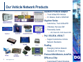
Quick Start Guide Fiber Optic Bridge CAN System DG-FO-BRIDGE-T System Please read all instructions BEFORE applying power Dearborn Group Technology is Vehicle Networks! 2 www.dgtech.com Vehicle Network Solutions 20+ Years in of expertise in Vehicle Networks Automotive, Truck & Bus/Heavy Duty Vehicle Networks Global Footprint & Partners Vehicle Network: Products Custom Products & Solutions Consulting Education & Training Conformance Testing Our Vehicle Network Products Dearborn Protocol Adapter Truck & Bus/HD Vehicles 6+ Models, DLM or OEM SW Gryphon Series Automotive, Truck & Bus/HD 3 Models, Hercules SW Personality Cards z Px2, VSI-2534, VSI/VLT FlexRay 3 Support Automotive Vehicle Network Standards Emerging Vehicle Network Standard, 20+ Products Protocol Mini-Module, AutoPak, DPA-on-a-Chip www.dgtech.com Customized Product Solutions Vehicle Network Solutions LIN, Dual-LIN, CAN, Quad-CAN DG Shipping Package Contents The Fiber-Optic Satellite T Module should includes the following items: CAN Fiber-Optic Bridge (Black box), including a 12 VDC Universal A/C power adapter CAN Fiber-Optic Satellite Module (nine-volt batteries not included) Two fiber-optic cables with SMA connectors (10 meters in length) CD with the user Manual for the Fiber-Optic Bridge http://www.dgtech.com/support/support_guide.html 4 www.dgtech.com Vehicle Network Solutions If you discover that you are missing any part of this package, please contact your Dearborn Group sales representative or the technical support hotline at once. Fiber-Optic Bridge Functions 5 The Bridge Adapter works as a pass-through hardware device. It translates the vehicle network electrical signals from the GRYPHON® tool (or a user’s host test device) into fiber-optic signals. These fiber-optic signals are used to interface with the Satellite Module placed in the EMC Test Chamber. The fiber-optic signals are then translated back into vehicle network electrical signals by the Satellite Module and used to communicate with the DUT. www.dgtech.com Vehicle Network Solutions The Fiber-Optic Bridge consists of two major components: 1. The Fiber-Optic Bridge Adapter 2. The Fiber-Optic Satellite Module. Fiber-Optic T Bridge Example Bridge Adapter/Gateway connection example using: • Bridge Adapter (Black Box) • Fiber Optic Satellite “T” module EMI/EMC Test Chamber FiberOptic cables Fiber-Optic Bridge Adapter Cable 1 Cable 2 DG Rx Tx DB15 Copper wire Customer Tester DG Gryphon Tool, Vector, ETAS, etc….. T copper card connector (DB15) output to external test system CAN L (-) = Pin 2 CAN H (+) = Pin 7 6 www.dgtech.com DUT Customer wiring CAN L (-) = Pin 14 CAN H (+) = Pin 6 Vehicle Network Solutions DG F-O Sat T Mod CAN Fiber Optic Bridge Vehicle Network Solutions 7 www.dgtech.com Pin Assignment Warning CAUTION Make only the connections to the DB 15 and DB 9 connectors as indicated in the instructions. Other pins contain signals and voltages and any connection made to them could cause damage to the hardware voiding the warranty. Fiber-Optic Cables/Wiring Pin Assignments Gryph Copper Card FO cables from the Satellite Connector (DB 15) To Customer Tester Bridge to the Satellite to the DUT (wired) 8 Cable 1 to Rx (Cable 1) Cable 2 to Tx (Cable 2) Pin 14 to CAN L (-) Pin 6 to CAN H (+) Note: When connecting the fiber-optic cables, always connect Cable 1 from the Bridge to Rx (Cable 1) on the Satellite, and Cable 2 from the Bridge to Tx (Cable 2) on the Satellite. Caution: Making a connection to any of the other pins of the DB 9 or DB15 connector could result in damage to the equipment. www.dgtech.com Vehicle Network Solutions Pin 2 to CAN L (-) Pin 7 to CAN H (+) CAN Termination Resistor First, connect the Bridge unit to your tester. On the BRIDGE unit, CAN HI is Pin 7 and CAN Low is Pin 2. You need to have a 120 ohm resistor across CAN HI & CAN Low. Your tester will also need a 120 ohm resistor across CAN HI & CAN Low, unless it has a built in, or software selectable internal terminating resistor. www.dgtech.com Vehicle Network Solutions 9 Remember, every CAN bus needs to be terminated at BOTH ends. The FO Bridge is ONE CAN bus. The FO Satellite is the SECOND CAN bus. Termination Resistor Bridge T Satellite module connector is CAN Bus # 2 requiring 120 Ohm termination resistor Bridge T copper card connector Is CAN Bus # 1 requiring 120 Ohm termination resistor Fiber- Optic cables Cable Cable 1 2 Rx Tx DG F-O Sat T Mod DG DB1 5 Copper wire T Copper card Customer Tester DG Gryphon Tool, Vector, ETAS, etc….. T copper card connector (DB15) output to external test system CAN L (-) = Pin 2 CAN H (+) = Pin 7 10 www.dgtech.com DUT Customer wiring CAN L (-) = Pin 14 CAN H (+) = Pin 6 Vehicle Network Solutions F-O T card EMI/EMC Test Chamber Fiber-Optic Bridge Adapter Checking for the CAN 120 Ohm Termination Resistor Presence Procedure: Put an Ohmmeter across CAN HI & Low pins. If you see a resistance of 120 ohms, it is terminated. If not, you will need to solder one in. If both ends are terminated, you will see a resistance of 60 ohms. www.dgtech.com Vehicle Network Solutions 11 How do I check my test system to determine if it already has a 120 Ohm termination resistor? T System Bridge Module 12 Power switch for the bridge This switch is used to apply/disconnect power to the CAN FiberOptic Bridge. Power to the unit is applied when the switch is placed in the “up” position. Power jack This standard 2.5 mm x 5.5 mm connector (with positive center pin) is used to provide power to the Fiber-Optic Bridge. This power jack is designed to accept an input range between 8 to 18 VDC. The typical operating voltage supplied by the included Universal Power Adapter is approximately 12 VDC. www.dgtech.com Vehicle Network Solutions IMPORTANT NOTE: When connecting the fiber-optic cables, always connect Cable 1 from the Bridge to Rx (Cable 1) on the Satellite, and Cable 2 from the Bridge to Tx (Cable 2) on the Satellite Module.) Fiber-Optic Satellite T Module The CAN Fiber-Optic Satellite Module is normally placed inside of the test chamber. It can be used for tests performed outside the chamber as well. The Figure below shows the CAN Fiber-Optic Satellite T Module. Cable 2 Pin 14 = CAN L (-) Pin 6 = CAN H (+) Switch shown in the ON position (left) 13 www.dgtech.com Vehicle Network Solutions Cable 1 T System Satellite Module 14 Power Switch This switch (marked I/O PWR on the unit) is used to turn power on or off to the CAN Satellite Module. Power is applied to the unit when the switch is moved to the left (I). Power to Satellite Module Power is supplied to the Fiber-Optic Satellite Module via two internal nine-volt batteries and may be turned on or off via the toggle switch. Battery compartment The Fiber-Optic Satellite Module is powered by two nine-volt batteries inserted into the battery compartment and connected as indicated on the label of the module. The cover lid over the batteries is designed to fit tightly and hold them in place. www.dgtech.com Vehicle Network Solutions Pin assignments: The DUT (Device Under Test) is connected to the Satellite module, using pin 14 for CAN L (-) signal, pin 6 for CAN H (+). DO NOT CONNECT ANY OTHER PINS! Power On and Battery Low Indicators for Satellite Module Battery Low LED This LED (farthest from the power switch) will NOT be illuminated during operation unless there is a low battery condition, in which case the LED will be turned on (Red). When this LED is illuminated, it indicates that the enclosed batteries are not providing sufficient power for the proper operation of the module and the batteries should be replaced. Note: Do not attempt to run further tests until the batteries have been replaced. www.dgtech.com Vehicle Network Solutions 15 Power On LED This LED (closest to the power switch) will be turned on when battery power is switched on. It remains on momentarily and then turns off. Bridge Fuse 16 The fuse in the bridge is a pretty common type. Littlefuse sells the product under the 'Nanofuse' name. The fuse in the bridge is a slow-blow 1.5A fuse; Digikey part number F2601. Other companies sell compatible fuses. www.dgtech.com Vehicle Network Solutions If the Bridge module is dead, check the fuse to see if it has opened the circuit. It is located on the top circuit board in a fuse socket near the ON/OFF switch. Fiber Optic Cables 17 The fiber optic cables contain glass tubes for signal transmission. They are easy to break if bent too far. DO NOT exceed 25mm bend radius A quick and easy test of the cable is to shine a light down one end of the cable. If the slightly bent cable transmits that light out the other end, it is not damaged. www.dgtech.com Vehicle Network Solutions Fiber Optic Cable Specs 100/140 Micro multimode fiber optic cable with SMA905 connectors Fiber Optic Satellite Module Isolation 18 The reason is the bypass caps typically are placed inside the fiber optic satellite modules from inputs to the Printed Circuit Board/Chassis. If the case of the fiber optic module: IS placed directly on the ground plane AND there are bypass caps inside the satellite module from input to chassis Then there is an additional RF path provided to travel. This can cause different behavior and this is what is being avoided by isolating the fiber optic module by 50mm insulation above the ground plane. www.dgtech.com Vehicle Network Solutions The FO SAT Modules need to be isolated by 50mm. This applies to all satellite modules and is not specific to DG’s. Dearborn Group Headquarters Vehicle Networks - Farmington Hills, MI Development & Engineering Automotive Vehicles Specialized Vehicle Applications 19 Technical Support Consulting Vehicle Network Education Sales & Marketing Product Shipping www.dgtech.com Vehicle Network Solutions Customized Solutions Military Applications Many More Heavy-Duty Truck & Bus Design Center Vehicle Networks - Indianapolis, IN Development & Engineering Heavy Duty Vehicles 20 Technical Support Sales Heavy-Duty Vehicle Network Education www.dgtech.com Vehicle Network Solutions Truck & Bus Construction Vehicles Agricultural Vehicles Many other applications DG’s Global Locations Indianapolis, IN Farmington Hills, MI Bruchsal, Göppingen Germany Beijing, Shanghai, China Seoul, Korea Tokyo, Japan Tainan, Taiwan Chihuahua, Mexico Central America Columbia, Equador 21 www.dgtech.com Sao Paulo, Brazil Bangalore India Vehicle Network Solutions Eureka, MT International Distributors Vehicle Network Solutions 22 www.dgtech.com Partnerships & Alliances Partnerships Alliances 23 www.dgtech.com Vehicle Network Solutions Contact Information 24 Dearborn Group Headquarters 27007 Hills Tech Court Farmington Hills, MI 48331 (248) 488-2080 (248) 488-2082 fax Dearborn Group Heavy-Duty Truck & Bus Division 2415 Directors Row Suite G Indianapolis, IN 46241 (317) 248-9332 (317) 248-1504 fax www.dgtech.com Vehicle Network Solutions www.dgtech.com