1
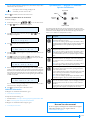
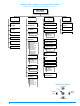
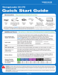
EXABYTE MAGNUM 1X7 AUTOLOADER
QUICK START GUIDE
Ethernet
cable
One Ethernet cable is provided. You can use this
cable to connect the autoloader to an Ethernet
network for remote monitoring, firmware upgrades,
and diagnostics. See the Product Manual for
instructions.
Use this guide to get your Exabyte Magnum 1x7 Autoloader up and
running quickly. If you need additional information, refer to the
Exabyte Magnum 1x7 Autoloader Product Manual available at
www.exabyte.com/manuals.
Rack-mount
hardware
The autoloader is designed to mount in a standard
19-inch rack, using 2 units (2U) of rack space.
Rack-mount hardware is included with the
autoloader.
As you install your autoloader, refer to the figures below and the
operator panel quick reference on page 5.
Cartridges
Use only data cartridges and cleaning cartridges
designed specifically for LTO Ultrium tape drives.
For maximum capacity, use Ultrium 2 data
cartridges with the LTO-2 tape drive and Ultrium 3
data cartridges with the LTO-3 tape drive.
FRONT
QUICK ST ART GUID E
Tape
Drive
LTO-3
Cartridge
Access Port
LCD
Keypad
Status
LED
BACK
LTO-2
Cartridges
Color
Native
Capacity
Ultrium 3
Slate Blue
400 GB
Ultrium 2
Purple
200 GB
Ultrium 1
(READ only)
Black
100 GB
WORMa
Two-toned
400 GB
Ultrium 2
Purple
200 GB
Ultrium 1
Black
100 GB
a
See the Product Manual for WORM cartridge
information.
Bar code
labels
Ethernet
port
SCSI
connectors
Power cord
connection
Power
switch
1 | PREPARING FOR INSTALLATION
Make sure that you have the equipment you need for installing and
operating the autoloader, as follows:
Power cord
SCSI cable(s)
Terminator
www.exabyte.com
Two power cords are included: one for use in the
US and Canada and one for use in Europe.
If you plan to use the autoloader outside of these
locations, refer to the Product Manual for
requirements.
One high-density (HD), wide (68-pin), 2-meter LVD
SCSI cable is provided with the autoloader.
If you want to use your own cable or terminator,
refer to the Product Manual for requirements.
Important! Both LTO-2 and LTO-3 SCSI tape drives
are Ultra 160 SCSI devices and require a minimum
Ultra 160 rated cabling.
If your SCSI controller has a 68-pin very
high-density (VHDCI) connector, you will need to
obtain either a VHDCI/HD converter to use the
supplied SCSI cable or a VHDCI-to-HD SCSI cable.
One wide Ultra 3 Active SCSI terminator is provided
with the autoloader.
If you want to use your own terminator, use a
high-quality Ultra 3 rated Active SCSI terminator. An
appropriate terminator is stamped with Ultra 3 or
LVD 160 and “Active Negation.”
Sample bar code labels for the cartridges are
included with the autoloader.
If you want to prepare your own labels, refer to the
Exabyte Bar Code Label Specification for LTO Ultrium
Cartridges on the documentation CD.
Important! Both LTO-2 and LTO-3 SCSI tape drives are Ultra 160
SCSI devices and require a minimum Ultra 160 non-RAID SCSI
adapter card, Ultra 160 rated cabling, and an Ultra 160 Active
terminator.
BEFORE BEGINNING AUTOLOADER INSTALLATION
Before installing the autoloader:
Make sure that the SCSI host bus adapter card installed in the
host computer, any necessary device drivers, and your backup
software are compatible with the autoloader. Make certain that
an Ultra 160 SCSI host bus adapter (HBA) and any necessary
drivers installed in the host computer are compatible with the tape
drive(s).
Important
Both LTO-2 and LTO-3 SCSI tape drives are Ultra 160
SCSI devices and require a minimum Ultra 160
non-RAID SCSI host bus adapter card.
For optimum performance, use an Ultra160 SCSI host bus
adapter. Compatibility information is available from
www.exabyte.com/compatibility.
If your software has not yet been certified for the Magnum 1x7
Autoloader, you can use one of the autoloader’s emulation
modes (see the Product Manual).
You can install the software on the host computer before or after
autoloader installation. However, if you install the software first,
you may need to reconfigure it for use with the autoloader after
autoloader installation is complete.
Locate an appropriate area for the autoloader. The autoloader is
designed to operate in a standard 19-inch rack. To provide
adequate air flow, a ventilated rack is recommended. If you do not
plan to install the autoloader in a rack, do not place the autoloader
on its side, and do not place objects on top of the autoloader. The
autoloader must be operated in the horizontal position.
Copyright 2006 Exabyte, EZ17, M2, VXA, and VXAtape are registered trademarks; ExaBotics, MammothTape, and SmartClean are trademarks; SupportSuite is a
service mark. Linear Tape-Open, LTO, the LTO Logo, Ultrium and the Ultrium Logo are trademarks of HP, IBM, and Quantum in the US and other countries. All
other product names are trademarks or registered trademarks of their respective owners.
P/N 1012583 F
October 2006
#1012583F#
Ensure that the work area is free from conditions that could cause
electrostatic discharge (ESD). Discharge static electricity from your body
by touching a known grounded surface, such as a computer’s metal
chassis.
Warning
Before performing any installation or maintenance
procedures, be sure that the autoloader’s power switch is off
and that the power cord is disconnected from the autoloader
and the outlet.
Warnung
Vor der Ausführung von Installations- oder Wartungsarbeiten
ist darauf zu achten, daß der Autoloader-Netzschalter auf
“Aus” gestellt ist und daß das Anschlußkabel vom Autoloader
und der Steckdose entfernt ist.
Antes de realizar cualquier procedimiento de instalación o de
mantenimiento, comprobar que el interruptor de
alimentación de la biblioteca está apagado y que el cable de
Advertencia alimentación no está enchufado ni a la biblioteca ni a la toma
de corriente.
2 | COMPLETING THE UNPACKING PROCESS
3 | CONNECTING THE AUTOLOADER TO SCSI
This section provides guidelines for connecting the autoloader to a host system
via SCSI. The autoloader includes two SCSI devices: the autoloader itself and
the tape drive. The two devices share one set of Ultra 160 SCSI connectors for
connection to a SCSI bus.
Do not connect the autoloader to a high-voltage differential
(HVD) SCSI bus. Doing so may damage the autoloader, tape
Caution drive, or other devices on the bus.
GUIDELINES FOR CONNECTING TO SCSI
Keep these guidelines in mind as you plan your SCSI connections:
Make sure the SCSI bus is LVD (Ultra 160). Do not connect the
autoloader to a high-voltage differential (HVD) SCSI bus.
Important
Both LTO-2 and LTO-3 SCSI tape drives are Ultra 160 SCSI
devices and require a minimum Ultra 160 non-RAID SCSI
host bus adapter card.
Do not connect single-ended SCSI devices. Although single-ended SCSI
Important
After unpacking the autoloader, save all the original packing
materials in case you need to ship or move the autoloader later.
is compatible with LVD Ultra-2 and Ultra-3 SCSI, Exabyte does not support
connecting single-ended devices to the SCSI bus attached to the
autoloader.
REMOVING THE SHIPPING KEY
Do not connect the autoloader to a RAID controller. The autoloader will
The robotic cartridge loader inside the autoloader is secured with a small
metal shipping key to keep the loader from moving during shipping. Before
operating the autoloader, you must remove this shipping key.
Do not exceed SCSI bus length restrictions. The maximum allowable
not operate if it is connected to a RAID controller.
To remove the shipping key:
length of an LVD SCSI bus is 12 meters (39 feet) if you have more than two
devices on the bus. Make sure the SCSI bus attached to the autoloader
does not exceed this length. To determine the length of the bus:
1. Remove the adhesive label securing the shipping key to the autoloader.
a.
Add together the lengths of all external SCSI cables on the bus.
b. Add 64 centimeters (25.2 inches) for the internal cable length used by
the autoloader and its tape drive.
c.
Add the internal cable lengths for any other SCSI devices on the bus.
Make sure the SCSI bus is properly terminated. You must install a
terminator on the device at the physical end of the SCSI bus. If the
autoloader terminates the SCSI bus, you must install the required
terminator on one of the autoloader’s SCSI connectors.
Important
Both LTO-2 and LTO-3 SCSI tape drives require an Ultra 3 or
LVD 160 terminator to function properly on the SCSI bus. An
inadequate terminator will result in various SCSI bus issues,
including bus hangs and Read/Write failures.
MAKING THE SCSI CONNECTIONS
Remove this label
2. Lift the shipping key up and out of the autoloader (see the following figure).
Save the shipping key with the autoloader’s packing materials in case you
need to re-ship the autoloader.
To connect the autoloader to SCSI:
1. Make sure that the autoloader is powered off (press the 0 on the back of
the unit).
2. Power off the host computer and any peripheral devices on the SCSI bus.
3. Connect a SCSI cable to the host computer and to one of the autoloader’s
SCSI connectors.
Autoloader IS last device on bus—install a terminator on the unused SCSI
connector.
Autoloader is NOT last device on bus—connect another SCSI cable from
Shipping key
INSTALLING THE AUTOLOADER IN A RACK
See the Rack-mounting instructions included with the autoloader.
2 of 6
the autoloader’s SCSI connector to the next device on the bus. For the
device at the physical end of the bus, install a terminator on one of the
SCSI connectors for that device.
Both LTO-2 and LTO-3 SCSI tape drives require an Ultra 3 or
Ultra 160 terminator to function properly on the SCSI bus. An
Important inadequate terminator will result in various SCSI bus issues,
including bus hangs and Read/Write failures. See FAQ #2025
at www.exabyte.com/support for details.
The following figure shows how to connect the autoloader as the last
device on a SCSI bus.
4. If necessary, set the SCSI IDs for the autoloader and the tape drive. You can
use the default IDs or change them if they conflict with other devices on
the SCSI bus. The SCSI IDs are set through the autoloader’s operator panel.
Refer to the Product Manual for instructions.
Do not power on the host computer system immediately
after powering on the autoloader. After you press the
Important autoloader’s power switch, there is a short delay before the
tape drive is on-line.
5. Power on the host computer system.
SCSI terminator
SCSI cable
4. Power on all of the peripheral devices on the SCSI bus.
5. Power on the autoloader as described in the Powering On the Autoloader.
4 | CONNECTING THE AUTOLOADER TO ETHERNET
This section provides guidelines for connecting the autoloader to an Ethernet
network.
To connect the autoloader to Ethernet using the provided cable:
6 | CONFIGURING THE AUTOLOADER
If desired, you can operate the autoloader without performing any
configuration. However, by configuring the autoloader, you can customize its
operation to your particular needs. Before putting the autoloader into
operation, check the list of optional configuration tasks below to determine if
there are any you want to perform. Instructions for these tasks are provided in
the Product Manual. See page 6 for a quick reference to autoloader menu
items.
Set the...
To...
LCD language
change the LCD language from English to French, German,
Spanish, Italian, or Portuguese.
LCD contrast
set the LCD contrast to an appropriate level for your
lighting conditions.
Emulation
mode
set the autoloader to emulate an Exabyte VXA AutoPak
1x10 autoloader, EZ17 autoloader, or 210 library (if your
application is not yet certified for the Magnum 1x7
Autoloader).
Automatic
tape drive
cleaning
set options that enable the autoloader to perform tape
drive cleanings when necessary, using a cleaning cartridge
stored in the autoloader.
2. Connect the other end of the cable to the network or directly to the server
you plan to use to run the autoloader’s Remote Management utility or
upload firmware.
Ethernet
interface
connect to the autoloader’s Ethernet interface to remotely
monitor and manage operation, upgrade firmware, and
create diagnostic listings.
When you perform autoloader configuration, you will configure the
autoloader’s Ethernet interface (see Section 6 – Configuring the Autoloader).
Sequential
operation
set options to allow the autoloader to process cartridges
sequentially without direction from an autoloader
application.
5 | POWERING ON THE AUTOLOADER
Password
protection
prevent unauthorized personnel from using operator panel
functions and possibly disrupting autoloader operation.
Number of
cells
configure the autoloader so that it reports only the number
of cells you use.
Some backup applications base licensing on the number of
cartridge cells in the autoloader. If you don’t plan to use all
of the cells in the autoloader initially, use this option to limit
the number of cells.
1. Insert one end of the cable into the autoloader’s Ethernet port until you
hear it snap into place. The Ethernet port is located on the back of the
autoloader, as shown in the following figure.
Ethernet port
To power on the autoloader:
1. Make sure that the power switch on the back of the autoloader is off (press
the 0).
2. Connect the female end of the power cord to the power connector on the
back of the autoloader. Connect the male end to the power source.
Important
Two power cords are shipped with the autoloader: One
for use in the US and Canada, and one for use in Europe.
Use the correct power cord for your location.
3. Push the power switch on the back of the autoloader to the “on” position
(press the I). After the autoloader performs its power-on sequence, the
Home screen appears on the LCD:
7 | CHECKING THE SETUP
Check the setup by performing the exercises suggested below. While these
exercises are not required, it is a good idea to verify that your software and
hardware are communicating properly before you begin operation.
Import several cartridges into the autoloader (see Section 9 – Inserting and
L T O
Ultrium 3-S
1x7
2 U
D217
Removing Cartridges). You may also want to run a system demo (see the
Product Manual for instructions). These exercises help determine whether
the autoloader’s hardware components are operating properly.
If you have not already done so, install the software application on the host
computer. Instruct the software to load and unload one or more cartridges
in the tape drive. This helps determine whether the software and
autoloader are communicating properly.
Back up several megabytes of data with the tape drive and perform a
comparison check on the backed-up data. This determines whether the
software and tape drive are communicating properly.
3 of 6
If the autoloader and tape drive are not operating as expected, see the
Product Manual for troubleshooting information.
8 | BEGINNING AUTOLOADER OPERATION
After you have installed your autoloader, you can add cartridges and put it
into operation. If you operate the autoloader in Random mode (the default),
your autoloader application controls which cartridges are moved to and from
the tape drive. If you operate the autoloader in Sequential mode (see the
Product Manual), the autoloader automatically processes the cartridges in
sequential order. In both cases, your backup application controls backup and
restore jobs in the tape drive.
INSERTING CARTRIDGES INTO THE AUTOLOADER
To insert cartridges:
1. At the Home screen, press
2. Press
,or
The autoloader...
Green
is performing a mechanical operation
Amber
has encountered a hardware error
Off (no color)
is idle
During normal operation, you do not need to intervene in autoloader
activities. However, to begin operation you will need to add cartridges, as
described in the following section. You may also occasionally need to remove
cartridges to store them.
Refer to the Product Manual for information about additional tasks you may
need to perform, including:
Loading and unloading cartridges in the tape drive
Cleaning the tape drive
Resetting the autoloader
Storing cartridges that you have removed from the autoloader
Viewing autoloader information such as code versions, sensor readings,
statistics, cartridge inventory data, and the event log
9 | INSERTING AND REMOVING CARTRIDGES
or
to access the main menus.
l
e c
t
a
C o m m a n d
3. Press
to see the menu selections, then press
following screen appears:
I m p o r
t
C a
i
4. Press
Color
,
until the command menu appears:
S e
You can monitor autoloader operations by viewing the operator panel. The
Home screen provides continuous updates on the activities of the autoloader
and tape drive. The status LED, located to the right of the operator panel
buttons, also indicates autoloader activity, as follows:
Status LED
,
r
t
r
or
until the
d g e s
to display the cell selection screen:
I m p o r
T o
t
C e
C a r
l
l
t
#
r
i
d g e
n
5. The autoloader automatically selects the empty cell closest to the door.
Press
or
to scroll through the available (empty) cell locations to
select a different cell.
6. Press
to start the import operation (or
to cancel). When the
specified cartridge cell is in position at the cartridge access port, the door
slides open and the following message appears:
L o a d
i
n
,
t
a p e
p u s h
,
l
a b e
a n y
l
k e y
7. Position the cartridge with the hub down and the side with the bar code
label and write-protect switch toward the door, as shown below.
Caution
Insert cartridges as shown in the following
figure. Do not insert cartridges with the label
and write-protect switch toward you. The
arrow on the top cartridge must face toward
the outside.
To insert and remove cartridges from the autoloader, you use the operator
panel and the cartridge access port.
Note: In the event of a power failure, you can operate the cartridge access
port manually if you need to remove cartridges. Refer to the Product Manual
for instructions.
For convenience, you can use cell 7 in the autoloader to store a cleaning
cartridge for the tape drive. Refer to the Product Manual for information that
will help you determine whether you want to store a cleaning cartridge in the
autoloader.
Arrow
PREPARING CARTRIDGES
Before inserting cartridges into the autoloader, prepare them as follows:
1. Affix the supplied bar code labels to the cartridges. Position each label as
shown in the following figure.
Note: The bar code labels provided with the autoloader include labels
for data cartridges and cleaning cartridges.
2. Set the write-protect switch on each cartridge for the desired operation, as
shown in the following figure.
8. Slide the cartridge fully through the access port until it snaps into place in
the cartridge cell.
9. Press any key. The door closes. The autoloader checks for the presence of
a cartridge in the specified cell, makes sure that the cartridge is seated
correctly, and updates the cartridge inventory. The cell selection screen
appears again with the next available cell number:
I m p o r
T o
0
0
0
A
Bar code label
0
1
L1
Write-protect switch
4 of 6
t
C e
C a r
l
l
#
t
r
n
i
d g e
You can continue importing cartridges in the same manner until you have
filled as many cells as you want.
Important
10. Press
Quick Reference — Magnum 1x7 Autoloader
Operator Panel Buttons
If you plan to store a cleaning cartridge in the
autoloader, you must store it in cell 7.
Up a Level
Select
(as needed) to return to the Home screen.
Previous
Choice
REMOVING CARTRIDGES FROM THE AUTOLOADER
To remove cartridges:
1. At the Home screen, press
2. Press
,
,
or
to access the main menus.
or
until the command menu appears:
S e
l
e c
t
a
4. Press
r
t
C a
r
i
r
t
Down a Level
C o m m a n d
3. Press
to see the menu selections, then press
following screen appears:
E x p o
or
until the
r
d g e s
F r o m
t
C a
C e
l
r
l
t
r
#
i
d g e
n
5. Press
or
to scroll through the occupied cell locations until the one
you want appears.
6. Press
to start the export operation (or
to cancel). When the
specified cartridge cell is in position at the cartridge access port, the door
slides open and the following message appears:
R e m o v e
P r e s s
C a
r
A n y
t
r
i
d g e
K e y
7. Reach through the access port, grasp the edge of the cartridge and pull it
straight out of the autoloader. Press any button to close the door. After the
door closes, the autoloader checks the cell to verify that the cartridge has
been removed. The autoloader also scans the affected cell to update its
cartridge inventory. The cell selection screen appears again with the next
available cell number:
E x p o
F r o m
r
t
C a
C e
l
l
r
t
r
#
i
d g e
n
You can continue removing cartridges in the same manner until you have
removed as many cartridges as necessary.
8. Press
The following table describes the actions performed by the operator panel
buttons. When the edges of a button are lit, the button is a valid choice for the
information currently displayed on the LCD. When the edges are dark, the
button is not a valid choice and performs no action.
Button
to display the cell selection screen:
E x p o
Next
Choice
(as needed) to return to the Home screen.
Description
Next Choice (right arrow). Press this button to move forward
through the selections in a menu.
Note: If you are entering a password, press this button to move
forward through the available values at a character position. Press
and hold the button to move rapidly through the available
values.
Previous Choice (left arrow). Press this button to move backward
through the selections in a menu.
Note: If you are entering a password, press this button to move
backward through the available values at a character position.
Press and hold the button to move rapidly through the available
values.
Down a Level (down arrow). Press this button to move down into
a lower level of menus. For example, if the screen is displaying
one of the main menus, press this button to view that menu’s
sub-menus.
Note: If you are entering a password, press this button to move
forward through the character positions of the password.
Up a Level (up arrow) Press this button to return to the previous
level of menus. At the top level of menus, pressing this button
returns to the Home screen.
If you are making selections within a menu and change your mind
about a selection, press this button to return to the previous
screen without enacting the change.
Note: If you are entering a password, press this button to move
backward through the character positions of the password.
Select. Press this button to cause an operation displayed on the
LCD to be enacted. For example, if you are changing a SCSI ID,
pressing this button causes the new value you have entered to
take effect.
As confirmation, after you press this button, the original screen for
changing the value reappears and displays the new value.
Additional Information
For Magnum 1x7 Autoloader documentation, go to:
www.exabyte.com/manuals
For tape drive documentation, go to:
Hewlett-Packard—www1.hp.com/storage/tapestorage/ultriumdrives.html
IBM—www.storage.ibm.com/tape/lto/oem/index.html
For Magnum 1x7 Autoloader technical support, go to:
www.exabyte.com/contact
REGISTER YOUR AUTOLOADER!
Be sure to register your Magnum 1x7 Autoloader for support
and product updates. You can register online at
www.exabyte.com/register.
5 of 6
Quick Reference—Magnum 1x7 Autoloader Menu Structure
(Keep this sheet close to your autoloader for reference)
Home Screen
Status and Messages
Select a
Command
View a
Status
Import
Cartridges
View Event Log
Total Even nn
Export
Cartridges
View Drive
Information?
Change a
Configuration
Perform a
Diagnostic
Change Librarys ID
Run Hardware
Self Test
Change Drives ID
Load Drive
Unload Drive
Update Inventory
1234567 –
Clean Drive?
Drive FW Level
Drive Serial #
Drive current SCSI ID
View Librarys
Information?
Library F/W Level
Library Serial #
Library current SCSI ID
Total Loads
Total Load Retries
Total Moves
Total Move Retries
DHCP Address
IP Address
Subnet Address
Gateway Address
Restore Default
Operating Mode
View a Cell
Information
Cell n Puts
Cell n Put Retries
Cell n Picks
Cell n Pick Retries
View Inventory:
1234567 –
Barcode Label
Run System Demo
Change Emulation
Reset Library
Native 2U
AutoPak 110
Exabyte 210
Exabyte EZ17
Change Fixed Cln Cell
Change AutoClean
Change Op. Mode
Random
Sequential
Change Password
Entry
Change Contrast on
LCD
Change Language
Change IP Addr.
Select DHCP
IP Address
Subnet Mask
Gateway Address
Drives Status
View Sensors
Information
Configurations?
Reset to Default
Door Open Sensor
Door Closed Sensor
Eject Sensor
Cell Sensor
Library Temperature
System Fan
Power Supply Fan
Operator Panel Buttons
Up a Level
Select
Next
Choice
Previous
Choice
Down a Level
6 of 6