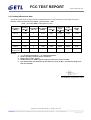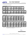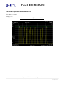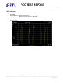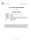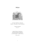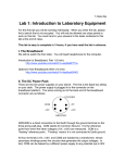
1
www.etl.re.kr Electromagnetic Emission FCC MEASUREMENT REPORT CERTIFICATION OF COMPLIANCE FCC Part 15 Certification Measurement PRODUCT : TPX Main Console MODEL/TYPE NO : a-01-01 / Proto-type FCC ID : VWV-A-01-01A BRAND NAME : APPLICANT : Adaptiv Technologies, LLC 1639 11th Street, Suite 156, Santa Monica, CA 90404, U.S.A. Attn.: Mr. Adam Gold / Director : MANUFACTURER Willtronics Co., Ltd 301 Kwanlidong, KwangMyung Industrial Complex, 201 Haan-3-Dong, KwangMyung, Kyungki, Korea, 423-063 FCC CLASSIFICATION : DSC : Part 15 Security/Remote Control Transmitter FCC RULE PART(S) : FCC Title 47, Part 15 Subpart C FCC PROCEDURE : ANSI C63.4-2003 TEST REPORT No. : ETLE100108.17 DATES OF TEST : January 12, 2010 to January 15, 2010 REPORT ISSUE DATE : January 25, 2010 TEST LABORATORY : ETL Inc. (FCC Designation Number : KR0022) This is TPX Main Console, Model a-01-01 has been tested in accordance with the measurement procedures specified in ANSI C63.4-2003 at the ETL Test Laboratory and has been shown to be complied with the electromagnetic radiated emission limits specified in FCC Rule Part15 Subpart C section 15.231. I attest to the accuracy of data. All measurement herein was performed by me or was made under my supervision and is correct to the best of my knowledge and belief. I assume full responsibility for the completeness of these measurements and vouch for the qualifications of all persons taking them. The results of testing in this report apply to the product/system which was tested only. Other similar equipment will not necessarily produce the same results due to production tolerance and measurement uncertainties. Hyung Seok, Lee / Chief Engineer ETL Inc. #371-51, Gasan-dong, Geumcheon-gu, Seoul, 153-803, Korea Tel: 82-2-858-0786 Fax: 82-2-858-0788 This report only responds to the tested sample and may not be reproduced, except in full, without written approval of the ETL Inc. FCC TEST REPORT FCC ID: VWV-A-01-01A Table of Contents FCC Measurement Report 1. Introduction 2. Product Information 3. Description of Tests 4. Test Condition 5. Test Results 5.1 Summary of Test Results 5.2 Radiated Emissions Measurement 5.3 Occupied Bandwidth Measurement 5.4 Radiated Emissions for Periodic radiators 5.5 Periodic Operation Measurement Plot 6. Sample Calculation 7. List of test Equipment used for Measurement Appendix A. FCC ID Label and Location Appendix B. Test Setup Photographs Appendix C. External Photographs Appendix D. Internal Photographs Appendix E. Block Diagram Appendix F. Schematics Appendix G. Operating Description and specifications Appendix H. User Manual Appendix I. Part list Appendix J. Component Appendix K. Antenna specification Report no. ETLE100108.17, Page 2 of 19 Head Office: # 371-51 Gasan-dong, Geumcheon-gu, Seoul, 153-803, Korea Tel : 82-2-858-0786 Fax : 82-2-858-0788 ETLQP-21-F22-0 FCC TEST REPORT FCC ID: VWV-A-01-01A FCC MEASUREMENT REPORT Scope – Measurement and determination of electromagnetic emission(EME) of radio frequency devices including intentional radiators and/or unintentional radiators for compliance with the technical rules and regulations of the U.S Federal Communications Commission(FCC) General Information Applicant Name : Adaptiv Technologies, LLC Address : 1639 11th Street, Suite 156, Santa Monica, CA 90404, U.S.A. Attention : Mr. Adam Gold / Director z EUT Type : TPX Main Console z Model Number : a-01-01 z FCC ID : VWV-A-01-01A z S/N : Proto-type z Freq. Range : 418 MHz z FCC Rule Part(s) : FCC Part 15 Subpart C section 15.231 z Test Procedure : ANSI C63.4-2003 z FCC Classification : DSC: Part 15 Security/Remote Control Transmitter z Dates of Tests : January 12, 2010 to January 15, 2010 z Place of Tests : ETL Inc. Testing Lab. Radiated Emission test; #499-1, Sagot-ri, Seosin-myeon, Hwaseong-si, Gyeonggi-do, 445-882, Korea Conducted Emission test; ETL Inc. Testing Lab. 371-51, Gasan-dong, Geumcheon-gu, Seoul, 153-803, Korea z Test Report No. : ETLE100108.17 Report no. ETLE100108.17, Page 3 of 19 Head Office: # 371-51 Gasan-dong, Geumcheon-gu, Seoul, 153-803, Korea Tel : 82-2-858-0786 Fax : 82-2-858-0788 ETLQP-21-F22-0 FCC TEST REPORT FCC ID: VWV-A-01-01A 1. INTRODUCTION The measurement test for radiated and conducted emission test was conducted at the ETL Inc. The site is constructed in conformance with the requirements of the ANSI C63.4-2003 and CISPR Publication 16. The ETL has site descriptions on file with the FCC for 3 m and 10 m site configurations. Detailed description of test facility was found to be in compliance with FCC Rules according to the ANSI C63.4-2003 and registered to the Federal Communications Commission (FCC Designation Number : KR0022). The measurement procedure described in American National Standard for Method of Measurement of RadioNoise Emission from Low-Voltage Electrical and Electronic Equipment in the Range of 9 kHz to 40 GHz (ANSI C63.4-2003) was used in determining radiated and conducted emissions from the Adaptiv Technologies, LLC Model: a-01-01 Report no. ETLE100108.17, Page 4 of 19 Head Office: # 371-51 Gasan-dong, Geumcheon-gu, Seoul, 153-803, Korea Tel : 82-2-858-0786 Fax : 82-2-858-0788 ETLQP-21-F22-0 FCC TEST REPORT FCC ID: VWV-A-01-01A 2. PRODUCT INFORMATION 2.1 Equipment Description The Equipment Under Test (EUT) is the TPX Main Console, Model: a-01-01 2.2 General Specification General Dimensions Weight Power Requirement 65 mm (W) x 118 mm (L) x 42 mm (H) 185 g CAR Battery 12 V DC Operating -20 ℃ to +80 ℃ Storage -40 ℃ to +100 ℃ Temperature Range Laser Detector Receiver Type Sensor Front End Detector Type Receiver Bandwidth Spectral Response Radar Detector Receiver Type Detector Type Antenna Type Pulse Laser Signal Receiver Convex Condenser Lens Pulse Width Discriminator 30 MHz 800 nm – 1 100 nm Frequency of Operation Double Conversion Super heterodyne Scanning Frequency Discriminator Linear Polarization 10.525 GHz (X Band) 24.150 GHz (K Band) 34.700 GHz (Ka Band) Transmitter Frequency(Tx) Transmitter Modulation Transmitter used in device Tolerance of transmission frequency Modulation contents Data rate Manual Tx & Semi Auto 418.00 MHz ASK (Amplitude shift keying) SAW (surface acoustic wave) RESONATOR NDR4047 ± 20 ppm Digital data 16 bit/70 ms Report no. ETLE100108.17, Page 5 of 19 Head Office: # 371-51 Gasan-dong, Geumcheon-gu, Seoul, 153-803, Korea Tel : 82-2-858-0786 Fax : 82-2-858-0788 ETLQP-21-F22-0 FCC TEST REPORT FCC ID: VWV-A-01-01A 3. DESCRIPTION OF TESTS 3.1 Radiated Emission Measurement Radiated emission measurements were made in accordance with § 13 in ANSI C63.4-2003 "Measurement of Intentional radiators” The measurements were performed over the frequency range of 30 MHz to 40 GHz using antenna as the input transducer to a Spectrum analyzer or a Field Intensity Meter. The measurements were made with the detector set for "Peak, Quasi-peak, Average" within a bandwidth of 120 kHz and above 1GHz is 1 MHz. Preliminary measurements were made at 3 m using broadband antennas, and spectrum analyzer to determine the frequency producing the maximum emission in shielded room. Appropriate precaution was taken to ensure that all emission from the EUT were maximized and investigated. The system configuration, mode of operation, turntable azimuth and height with respect to the antenna were noted for each frequency found. The spectrum was scanned from 30 MHz to 1000 MHz using Log-Bicon antenna. Above 1 GHz, linearly polarized double ridge horn antennas were used. Final measurements were made open site at 3 m. The test equipment was laced on a wooden turn-table. Sufficient time for the EUT, support equipment, and test equipment was allowed in order for them to warm up to their normal operating condition. Each frequency found during pre-scan measurements was re-examined by manual. The detector function was set to CISPR Quasi-peak mode and the bandwidth of the receiver was set to 120 kHz or 1 MHz depending on the frequency of type of signal. The EUT, support equipment and interconnecting cables were re-configured to the set-up producing the maximum emission for the frequency and were placed on top of a 0,8 m high nonmetallic 1m x 1.5 m table. The EUT, support equipment, and interconnecting cables were re-arranged and manipulated to maximize each emission. The turntable containing the system was rotated; the antenna height was varied 1 m to 4 m and stopped at the azimuth or height producing the maximum emission. Varying the mode of operating frequencies of the EUT maximized each emission. The system was tested in all the three orthogonal planes and changing the polarity of the antenna. The worst-case emissions are recorded in the data tables. If necessary, the radiated emission measurement could be performed at a closer distance to ensure higher accuracy and the results were extrapolated to the specified distance using an inverse linear distance extrapolation factor (20 dB/decade) as per section 15.31(f). Photographs of the worst-case emission can be seen in Photographs of the worst-case emission test setup can be seen in Appendix B. Report no. ETLE100108.17, Page 6 of 19 Head Office: # 371-51 Gasan-dong, Geumcheon-gu, Seoul, 153-803, Korea Tel : 82-2-858-0786 Fax : 82-2-858-0788 ETLQP-21-F22-0 FCC TEST REPORT FCC ID: VWV-A-01-01A 3.2 FCC Part 15.205 Restricted Bands of Operations (a) Except as shown in paragraph (d) of this section, only spurious emissions are permitted in any of the frequency bands listed below: MHz MHz MHz 0.090 - 0.110 399.9 - 410 16.42 - 16.423 1 0.495 - 0.505 608 - 614 16.69475 - 16.69525 2.1735 - 2.1905 960 - 1240 16.80425 - 16.80475 4.125 - 4.128 1300 - 1427 25.5 - 25.67 4.17725 - 4.17775 1435 - 1626.5 37.5 - 38.25 4.20725 - 4.20775 1645.5 - 1646.5 73 - 74.6 6.215 - 6.218 1660 - 1710 74.8 - 75.2 6.26775 - 6.26825 1718.8 - 1722.2 108 - 121.94 6.31175 - 6.31225 2200 - 2300 123 - 138 8.291 - 8.294 2310 - 2390 149.9 - 150.05 8.362 - 8.366 2483.5 - 2500 156.52475 - 156.52525 8.37625 - 8.38675 2690 - 2900 156.7 - 156.9 8.41425 - 8.41475 3260 - 3267 162.0125 - 167.17 12.29 - 12.293 3332 - 3339 167.72 - 173.2 12.51975 - 12.52025 3345.8 - 3358 240 - 285 12.57675 - 12.57725 3600 - 4400 322 - 335.4 13.36 - 13.41 1 Until February 1, 1999, this restricted band shall be 0.490-0.510 MHz. 2 Above 38.6 GHz 4.5 - 5.15 5.35 - 5.46 7.25 - 7.75 8.025 - 8.5 9.0 - 9.2 9.3 - 9.5 10.6 - 12.7 13.25 - 13.4 14.47 - 14.5 15.35 - 16.2 17.7 - 21.4 22.01 - 23.12 23.6 - 24.0 31.2 - 31.8 36.43 - 36.5 (2) (b) Except as provided in paragraphs (d) and (e), the field strength of emissions appearing within these frequency bands shall not exceed the limits shown in Section 15.209. At frequencies equal to or less than 1000 MHz, compliance with the limits in Section 15.209 shall be demonstrated using measurement instrumentation employing a CISPR quasi-peak detector. Above 1000 MHz, compliance with the emission limits in Section 15.209 shall be demonstrated based on the average value of the measured emissions. The provisions in Section 15.35 apply to these measurements. Report no. ETLE100108.17, Page 7 of 19 Head Office: # 371-51 Gasan-dong, Geumcheon-gu, Seoul, 153-803, Korea Tel : 82-2-858-0786 Fax : 82-2-858-0788 ETLQP-21-F22-0 FCC TEST REPORT FCC ID: VWV-A-01-01A 4. TEST CONDITION 4.1 Test Configuration The device was configured for testing in a typical fashion (as a customer would normally use it). During the tests, the EUT and the supported equipments were installed to meet FCC requirement and operated in a manner and which tends to maximize its emission level in a typical application. 4.2 EUT operation The EUT was connected as user’s guide. And during the test executed EUT is operating on the following - Function of transmitter The EUT (model: a-01-01) has been tested under operating condition. Fixed Channel (418 MHz) was chosen for testing. - Function of Radar detector Bands: 10.525 GHz (X-Band), 24.150 GHz (K-Band), 34.700 GHz (Ka-Band) Operating Mode Stand-by mode 10.525 GHz (X-Band) 24.150 GHz (K-Band) 34.700 GHz (Ka-Band) 4.3 Support Equipment Used Description Model Name Serial No. Manufacturer Receiver Speaker NONE NONE NONE Laser Receiver WL-1000 01739 NONE Laser Generator NONE NONE NONE Speaker NONE NONE NONE LED NONE NONE NONE DC Power Supply E3616A KR64301658 H.P. 4.4 Type of Cables Used Device from Device to Type of I/O port Length[m] Type of shield EUT Laser Receiver Line 2.5 Shielded EUT Speaker Line 2.5 Unshielded EUT LED Line 2.5 Unshielded EUT Car Battery Line 1.5 Unshielded Laser Generator DC Power Supply Line 1.5 Unshielded DC Power Supply Power socket AC Input 1.0 Unshielded Report no. ETLE100108.17, Page 8 of 19 Head Office: # 371-51 Gasan-dong, Geumcheon-gu, Seoul, 153-803, Korea Tel : 82-2-858-0786 Fax : 82-2-858-0788 ETLQP-21-F22-0 FCC TEST REPORT FCC ID: VWV-A-01-01A 4.5 The setup drawing(s) Car Battery DC Power Supply Laser Generator Receiver Speaker EUT Laser Receiver Speaker LED : Data Line : DC Power Line : AC Power Line Report no. ETLE100108.17, Page 9 of 19 Head Office: # 371-51 Gasan-dong, Geumcheon-gu, Seoul, 153-803, Korea Tel : 82-2-858-0786 Fax : 82-2-858-0788 ETLQP-21-F22-0 FCC TEST REPORT FCC ID: VWV-A-01-01A 5. TEST RESULTS 5.1 Summary of Test Results The measurement results were obtained with the EUT tested in the conditions described in this report. Detailed measurement data and plots showing the maximum emission of the EUT are reported. Applied Standard : 47 CFR Part 15, Subpart C FCC Rule 15.207(a) Measurement Required Power line Conducted Emissions Result Remarks N/A 1) 15.231(a)(1) Manually operated transmitter Pass 15.231(a)(2) Automatically activated transmitter Pass 15.231(a)(3) Periodic transmissions at regular predetermined intervals Pass 15.231(a)(4) Radiators used in cases of emergency Pass 15.231(a)(5) Set-up information for security systems Pass 15.209(a),231(b) Radiated Emissions Pass 15.231(c) 20 dB Bandwidth 15.231(d) Devices operating within the frequency band 40.66 MHz - 40.70 MHz N/A 15.231(e) Radiated emissions for Periodic radiators N/A Pass 2) Notes: 1) The EUT is powered by DC power supply that uses battery only. 2) The frequency range of EUT is 418 MHz fixed. The data collected shows that the Adaptiv Technologies, LLC / TPX Main Console / a-01-01 complied with technical requirements of above rules part 15.209 and 15.231 limits. The equipment is not modified anything, mechanical or circuits to improve EMI status during a measurement. No EMI suppression device(s) was added and/or modified during testing. Report no. ETLE100108.17, Page 10 of 19 Head Office: # 371-51 Gasan-dong, Geumcheon-gu, Seoul, 153-803, Korea Tel : 82-2-858-0786 Fax : 82-2-858-0788 ETLQP-21-F22-0 FCC TEST REPORT FCC ID: VWV-A-01-01A 5.2 20 dB Bandwidth EUT TPX Main Console / a-01-01 Limit apply to FCC Part 15. 231(c) Test Date January 12, 2010 Operating Condition Continues transmitter (418 MHz) Result Passed Limit The bandwidth of the emission shall be no wider than 0.25% of the center frequency for devices operating above 70 MHz and below 900 MHz. For devices operating above 900 MHz, the emission shall be no wider than 0.5% of the center frequency. Bandwidth is determined at the points 20 dB down from the modulated carrier. Test Data Center Frequency [MHz] Measured occupied bandwidth [MHz] Limit [MHz] Result 418.00 0.470 1.045 (0.25%) Pass NOTES: 1. 2. Please see the measured bandwidth plot in next page. The bandwidth is determined at the points 20 dB down from the modulated carrier. Test Engineer: Kug Kyoung, Yoon Report no. ETLE100108.17, Page 11 of 19 Head Office: # 371-51 Gasan-dong, Geumcheon-gu, Seoul, 153-803, Korea Tel : 82-2-858-0786 Fax : 82-2-858-0788 ETLQP-21-F22-0 FCC TEST REPORT FCC ID: VWV-A-01-01A 20 dB Bandwidth Report no. ETLE100108.17, Page 12 of 19 Head Office: # 371-51 Gasan-dong, Geumcheon-gu, Seoul, 153-803, Korea Tel : 82-2-858-0786 Fax : 82-2-858-0788 ETLQP-21-F22-0 FCC TEST REPORT FCC ID: VWV-A-01-01A 5.3 Radiated Emissions for Periodic radiators EUT TPX Main Console / a-01-01 Limit apply to FCC Part 15. 209(a) & 15.231(b) Test Date January 15, 2010 Operating Condition Continues transmitter (418 MHz) Result Passed Part 15.209(a) except as provided elsewhere in this Subpart, the emissions from an intentional radiator shall not exceed the field strength levels specified in the following table: Frequencies [MHz] 15.209 Radiated Limits [dB(uV/m) @ 3 m] 30 - 88 40 88 - 216 43.5 216 - 960 46 Above 960 54 Part 15.231(b) In addition to the provisions of Section 15.205, the field strength of emissions from intentional radiators operated under this Section shall not exceed the following: Fundamental Frequency [MHz] Field Strength of Fundamental [microvolts/meter] Field Strength of Spurious Emission [microvolts/meter] 40.66 - 40.70 70 - 130 130 - 174 174 - 260 260 - 470 Above 470 2 250 1 250 1 250 to 3 750** 3 750 3 750to 12 500** 12 500 225 125 125 to 375** 375 375 to 1 250** 1 250 ** linear interpolations [Where F is the frequency in MHz, the formulas for calculating the maximum permitted fundamental field strengths are as follows: for the band 130-174 MHz, uV/m at 3 meters = 56,81818(F) - 6 136,3636; for the band 260-470 MHz, uV/m at 3 meters = 41,6667(F) - 7 083,3333. The maximum permitted unwanted emission level is 20 dB below the maximum permitted fundamental level.] Fundamental: uV/m at 3 meters = 41.6667(418) - 7 083.3333 = 10 333.3473 = 20log*10 333.3473 = 80.28 dB(㎶/m) Spurious emissions: uV/m at 3 meters = 20 dB below of fundamental level = 60.28 dB(㎶/m) Test Results - Refer to see the measured plot in next page. Report no. ETLE100108.17, Page 13 of 19 Head Office: # 371-51 Gasan-dong, Geumcheon-gu, Seoul, 153-803, Korea Tel : 82-2-858-0786 Fax : 82-2-858-0788 ETLQP-21-F22-0 FCC TEST REPORT FCC ID: VWV-A-01-01A 5.3.1 Radiated Emissions Data The following table shows the highest levels of radiated emissions on both polarizations of horizontal and vertical. Detector mode: Quasi-Peak mode (RBW: 120 kHz) below 1 GHz Peak – AV mode (RBW: 1 MHz) above 1 GHz Polarization Ant. Factor Cable Loss (*H/**V) [dB/m] [dB(㎶)] Emission Limit Level [dB(㎶/m)] [dB(㎶/m)] Frequency [MHz] Reading [dB(㎶)] 121.13 17.70 V 11.29 2.21 31.20 43.50 12.30 190.65 19.76 V 9.87 2.87 32.50 43.50 11.00 193.35 21.08 V 9.63 2.89 33.60 43.50 9.90 229.80 21.26 H 10.15 3.09 34.50 46.00 11.50 399.75 17.06 H 14.54 4.60 36.20 46.00 9.80 Other frequencies - - - - - - - Margin [dB] NOTES: 1. 2. 3. 4. 5. * H : Horizontal polarization , ** V : Vertical polarization Result = Reading + Antenna factor + Cable loss Margin value = Limit – Result Results found to be 20dB or greater under the limit have not been included. The measurement was performed for the frequency range 30 MHz – 4.2 GHz according to the FCC Part 15.209(a) Test Engineer: Kug Kyoung, Yoon Report no. ETLE100108.17, Page 14 of 19 Head Office: # 371-51 Gasan-dong, Geumcheon-gu, Seoul, 153-803, Korea Tel : 82-2-858-0786 Fax : 82-2-858-0788 ETLQP-21-F22-0 FCC TEST REPORT FCC ID: VWV-A-01-01A 5.3.2 Field Strength of Fundamental Peak Mode Test Data Frequency [MHz] Reading [dB(㎶)] 418.00 40.18 Limit Polarization Ant. Factor Cable Loss Result (*H/**V) [dB/m] [dB(㎶)] [dB(㎶/m)] [dB(㎶/m)] H 15.11 4.71 60.00 100.28 Margin [dB] 40.28 Average Mode Test Data Frequency Reading Polarization Ant. Factor Cable Loss [MHz] (*H/**V) [dB/m] [dB(㎶)] [dB(㎶)] 418.00 H 36.26 15.11 4.71 Duty Cycle Result Limit Factor [dB(㎶/m)] [dB(㎶/m)] [dB] -29.82 26.26 80.28 Margin [dB] 54.02 5.3.3 Spurious Emissions Data Peak Mode Test Data Limit Polarization Ant. Factor Cable Loss Result (*H/**V) [dB/m] [dB(㎶)] [dB(㎶/m)] [dB(㎶/m)] Frequency [MHz] Reading [dB(㎶)] 836.00 23.93 H 21.95 7.42 53.30 80.28 26.98 1 254.00 15.90 H 24.90 11.50 52.30 80.28 27.98 Other frequencies - - - - - - - Margin [dB] Average Mode Test Data Frequency Reading Polarization Ant. Factor Cable Loss (*H/**V) [dB/m] [MHz] [dB(㎶)] [dB(㎶)] Duty Cycle Result Limit Factor [dB(㎶/m)] [dB(㎶/m)] [dB] Margin [dB] 836.00 19.13 H 21.95 7.42 -29.82 18.68 60.28 41.16 1 254.00 11.84 H 24.90 11.50 -29.82 18.42 60.28 41.86 Other frequencies - - - - - - - - NOTES: 1. 2. th The test was searched from 30 MHz to the 10 Harmonic.(30MHz – 4.2GHz) Average level = Peak level + Duty factor. Test Engineer : Kug Kyoung, Yoon Report no. ETLE100108.17, Page 15 of 19 Head Office: # 371-51 Gasan-dong, Geumcheon-gu, Seoul, 153-803, Korea Tel : 82-2-858-0786 Fax : 82-2-858-0788 ETLQP-21-F22-0 FCC TEST REPORT FCC ID: VWV-A-01-01A 5.4 Periodic Operation Measurement Plot TX on time = 11.71 ms Limit(s) = 5 s Result ■ Pass Fail Report no. ETLE100108.17, Page 16 of 19 Head Office: # 371-51 Gasan-dong, Geumcheon-gu, Seoul, 153-803, Korea Tel : 82-2-858-0786 Fax : 82-2-858-0788 ETLQP-21-F22-0 FCC TEST REPORT FCC ID: VWV-A-01-01A 5.4 .1 Duty cycle Calculation; Duty cycle factor = 20log (on time/period) 20log (0.19*17 ms/100 ms) = -29.82 dB On time = 0.19 ms * 17 = 3.23 ms Period = 100 ms Report no. ETLE100108.17, Page 17 of 19 Head Office: # 371-51 Gasan-dong, Geumcheon-gu, Seoul, 153-803, Korea Tel : 82-2-858-0786 Fax : 82-2-858-0788 ETLQP-21-F22-0 FCC TEST REPORT FCC ID: VWV-A-01-01A 6. SAMPLE CALCULATION Sample Field Strength Calculation The field strength is calculated by adding the Antenna Factor and Cable Factor. The basic equation with a sample calculation is as follows: FS = RA + AF + CF Where FS = Field Strength RA = Receiver Amplitude AF = Antenna Factor CF = Cable Attenuation Factor dB(μV) = 20 log10 (μV) dBμV = dBm + 107 Example : @ 399.75 MHz Class B Limit = 46.00 dB(㎶/m) Reading = 17.06 dB(㎶) Antenna Factor + Cable Loss Total Margin = 14.54 + 4.60 = 19.14 dB(㎶/m) = 36.20 dB(㎶/m) = 46.00 – 36.20 = 9.80 dB = 9.80 dB below Limit Report no. ETLE100108.17, Page 18 of 19 Head Office: # 371-51 Gasan-dong, Geumcheon-gu, Seoul, 153-803, Korea Tel : 82-2-858-0786 Fax : 82-2-858-0788 ETLQP-21-F22-0 FCC TEST REPORT FCC ID: VWV-A-01-01A 7. List of test equipments used for measurements Test Equipment Model Mfg. Serial No. Cal. Due Date Spectrum Analyzer E7405A H.P US41160290 10.09.18 EMI TEST Receiver ESVS10 R&S 835165/001 10.04.02 Horn Antenna BBHA 9120D Schwarzbeck 227 11.03.16 LogBicon Antenna VULB9160 Schwarzbeck 3082 10.01.25 Preamplifier 8447D H.P 3307A02865 10.10.05 Turn-Table MFT-120S Max-Full Antenna Corp - N/A Antenna Master MFA-440E Max-Full Antenna Corp - N/A Report no. ETLE100108.17, Page 19 of 19 Head Office: # 371-51 Gasan-dong, Geumcheon-gu, Seoul, 153-803, Korea Tel : 82-2-858-0786 Fax : 82-2-858-0788 ETLQP-21-F22-0