1
User Manual
English
VH GigE series
Revision History
Version
Date
1.0
2013-01-24
1.1
2013-06-14
1.2
2014-07-25
Description
Draft
Added description of M5 set screws for tilt adjustment
Revised spectral response to be separated by mono and color
Added the Exposure Auto and Gain Auto features
Added lwIP (lightweight IP) TCP/IP implementation
2 of 105
RA14-131-018
VH GigE series
Contents
1
2
3
4
5
Precautions ....................................................................................................................... 6
Warranty ............................................................................................................................ 7
Compliance & Certifications ............................................................................................ 7
3.1
FCC Compliance ............................................................................................................. 7
3.2
CE : DoC ......................................................................................................................... 7
3.3
KC ................................................................................................................................... 7
Package Components ...................................................................................................... 8
Product Specifications ................................................................................................... 10
5.1
Model ............................................................................................................................ 10
5.2
Specifications .................................................................................................................11
5.3
Camera Block Diagram ................................................................................................. 13
5.4
Spectral Response ........................................................................................................ 14
5.4.1
Mono Camera Spectral Response ................................................................................................. 14
5.4.2
Color Camera Spectral Response .................................................................................................. 17
5.5
6
7
8
9
Mechanical Specification ............................................................................................... 20
Software Licensing Information .................................................................................... 23
Connecting the Camera.................................................................................................. 24
7.1
Mount Plate ................................................................................................................... 24
7.2
Precaution to Center the Image Sensor ......................................................................... 25
7.3
Precaution about Blurring Compared to Center ............................................................. 25
7.4
Installing Vieworks Imaging Solution.............................................................................. 25
Camera Interface ............................................................................................................. 26
8.1
General Description ....................................................................................................... 26
8.2
RJ-45 Jack .................................................................................................................... 27
8.3
Control Receptacle ........................................................................................................ 28
8.4
Power Input Receptacle................................................................................................. 29
8.5
Trigger Input Circuit ....................................................................................................... 30
8.6
Strobe Output Circuit ..................................................................................................... 30
Acquisition Control......................................................................................................... 31
9.1
Overview ....................................................................................................................... 31
9.2
Acquisition Start/Stop Commands and Acquisition Mode ............................................... 34
3 of 105
RA14-131-018
VH GigE series
9.3
Exposure Start Trigger ................................................................................................... 35
9.3.1
Trigger Mode .................................................................................................................................. 35
9.3.2
Using a Software Trigger Signal ..................................................................................................... 38
9.3.3
Using an External Trigger Signal .................................................................................................... 39
9.3.4
Trigger Delay .................................................................................................................................. 42
9.4
9.4.1
Setting the Exposure Time............................................................................................. 43
Exposure Auto ................................................................................................................................ 44
9.5
Overlapping Exposure with Sensor Readout ................................................................. 45
9.6
Real Exposure ............................................................................................................... 48
9.6.1
Timed Exposure Mode .................................................................................................................... 48
9.6.2
Trigger Width Exposure Mode ........................................................................................................ 49
9.7
Acquisition Timing Chart ................................................................................................ 51
9.8
Maximum Allowed Frame Rate ...................................................................................... 53
9.8.1
Increasing the Maximum Allowed Frame Rate ............................................................................... 54
10 Camera Features ............................................................................................................. 55
10.1
Image Region of Interest ............................................................................................... 55
10.2
Binning .......................................................................................................................... 59
10.3
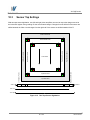
Sensor Tap Settings ...................................................................................................... 61
10.4
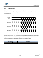
Pixel Format .................................................................................................................. 64
10.5
Pixel Clock..................................................................................................................... 69
10.6
Stream Hold................................................................................................................... 70
10.7
Inter-Packet Delay ......................................................................................................... 71
10.8
Data ROI ....................................................................................................................... 72
10.9
Exposure Auto and Gain Auto ........................................................................................ 74
10.10
Balance White Auto (Color Cameras) ............................................................................ 77
10.11
Gain and Black Level ..................................................................................................... 78
10.11.1
Analog Domain ....................................................................................................................... 78
10.11.2
Digital Domain ......................................................................................................................... 79
10.12
LUT ............................................................................................................................... 80
10.13
Defective Pixel Correction ............................................................................................. 82
10.13.1
Correction Method .................................................................................................................. 82
10.13.2
Correction Method in Binning Mode ....................................................................................... 83
10.14
Flat Field Correction ...................................................................................................... 84
10.15
Temperature Monitor ..................................................................................................... 87
10.16
Status LED .................................................................................................................... 87
4 of 105
RA14-131-018
VH GigE series
10.17
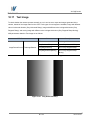
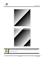
Test Image ..................................................................................................................... 88
10.18
Reverse X ..................................................................................................................... 90
10.19
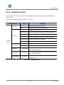
Digital IO Control ........................................................................................................... 91
10.20
Event Control................................................................................................................. 92
10.21
Device User ID .............................................................................................................. 93
10.22
Device Reset ................................................................................................................. 93
10.23
User Set Control ............................................................................................................ 94
10.24
Field Upgrade ................................................................................................................ 94
Appendix A
Appendix B
B.1
Defective Pixel Map Download ................................................................... 95
LUT Download ............................................................................................. 97
Luminance LUT ............................................................................................................. 97
B.1.1
Gamma Graph Download ............................................................................................................... 97
B.1.2
CSV File Download ........................................................................................................................ 99
Appendix C
Field Upgrade............................................................................................. 101
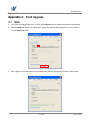
C.1
MCU ............................................................................................................................ 101
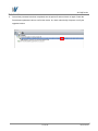
C.2
FPGA .......................................................................................................................... 103
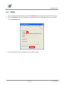
C.3
XML ............................................................................................................................. 104
5 of 105
RA14-131-018
VH GigE series
1
Precautions
General
Do not drop, disassemble, repair or alter the device. Doing so may damage the camera
electronics and cause an electric shock.
Do not let children touch the device without supervision.
Stop using the device and contact the nearest dealer or manufacturer for technical
assistance if liquid such as water, drinks or chemicals gets into the device.
Do not touch the device with wet hands. Doing so may cause an electric shock.
Do not store the device at a higher temperature. In addition, maintain the temperature of
the camera housing in a range of -5℃ to 40℃ during operation. Otherwise the device
may be damaged by excessively high temperatures.
Installation and Maintenance
Do not install in dusty or dirty areas - or near an air conditioner or heater to reduce the
risk of damage to the device.
Avoid installing and operating in an extreme environment where vibration, heat, humidity,
dust, strong magnetic fields, explosive/corrosive mists or gases are present.
Do not apply excessive vibration and shock to the device. This may damage the device.
Avoid direct exposure to a high intensity light source. This may damage the image
sensor.
Do not install the device under unstable lighting conditions. Severe lighting change will
affect the quality of the image produced by the device.
Do not use solvents or thinners to clean the surface of the device. This can damage the
surface finish.
Power Supply
Applying incorrect power can damage the camera. If the voltage applied to the camera is
greater or less than the camera’s nominal voltage, the camera may be damaged or
operate erratically. Please refer to 5.2 Specifications for the camera’s nominal voltage.
※ Vieworks Co., Ltd. does NOT provide power supplies with the devices.
Make sure the power is turned off before connecting the power cord to the camera.
Otherwise, damage to the camera may result.
6 of 105
RA14-131-018
VH GigE series
2
Warranty
Do not open the housing of the camera. The warranty becomes void if the housing is opened.
For information about the warranty, please contact your local dealer or factory representative.
3
Compliance & Certifications
3.1
FCC Compliance
This equipment has been tested and found to comply with the limits for a Class A digital device, pursuant to part
15 of the FCC Rules. These limits are designed to provide reasonable protection against harmful interference
when the equipment is operated in a commercial environment. This equipment generates, uses, and can radiate
radio frequency energy and, if not installed and used in accordance with the instruction manual, may cause
harmful interference to radio communications. Operation of this equipment in a residential area is likely to cause
harmful interference in which case the user will be required to correct the interference at his own expenses.
3.2
CE : DoC
EMC Directive 2004/108/EC.
Testing Standard EN 55022:2006+A1:2007, EN 55024:1998+A1:2001+A2:2003
Class A
3.3
KC
KCC Statement
Type
Description
Class A
This device obtained EMC registration for office use (Class A), and may
(Broadcasting Communication
be used in places other than home. Sellers and/or users need to take
Device for Office Use)
note of this.
7 of 105
RA14-131-018
VH GigE series
4
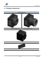
Package Components
Package Components
VH Camera with C mount,
VH Camera with F mount or
VH-310G2 Camera with C mount
Mount Plate (Optional)
8 of 105
RA14-131-018
VH GigE series
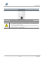
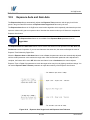
Package Components
M5 Set Screws for Tilt Adjustment (Provided only with F-mount camera)
You can adjust the tilt using the M5 set screws, however it is not recommended since it
is adjusted as factory default settings.
If the tilt settings need to be adjusted inevitably, please contact your local dealer or
factory representative for technical support.
9 of 105
RA14-131-018
VH GigE series
5
Product Specifications
5.1
Model
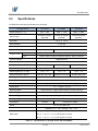
VH GigE series is a progressive scan high performance industrial digital camera. All features of the camera can
be easily updated in the field through Gigabit Ethernet interface. The camera uses the latest CCD technology
from Truesense Imaging, Inc. (formerly Kodak Imaging Solution) and Sony which provides superior low noise
performance resulting in high dynamic range. The camera is developed based on GenICam standard. The
image processing and controls of VH GigE series are based on embedded FPGA with a 32 bit microprocessor.
Main Features
Normal and High Speed Operation Modes
×1, ×2, ×3, ×4, ×8 Horizontal and Vertical Binning
Real Exposure
Stream Hold
Inter-Packet Delay
Camera Image Memory: 128 MB
Field Upgradable Firmware
Pixel Defect Correction (Binning Mode: 2×2, 4×4)
Excellent Dynamic Range and Noise Performance
Auto Exposure, Auto Gain Controls
10 of 105
RA14-131-018
VH GigE series
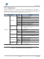
5.2
Specifications
VH GigE series technical specifications are as follows.
VH GigE Series
Active Image (H × V)
Sensor Type
VH-310G2
VH-2MG2
VH-4MG2
640 × 480
1600 × 1200
2048 × 2048
Truesense Imaging
Truesense Imaging
Truesense Imaging
KAI-0340
KAI-2020
KAI-0421
7.4 ㎛ × 7.4 ㎛
Pixel Size
Sensor Output
1 or 2 Tap
Video Output
8/10/12 bits
> 60 ㏈
Dynamic Range
> 62 ㏈
Mono
Mono8, Mono10, Mono10 packed, Mono12, Mono12 packed
Color
Bayer8, Bayer10, Bayer10 packed, Bayer12, Bayer12 packed
Output Format
Camera Interface
Gigabit Ethernet
Electronic Shutter
Global Shutter
Max. Frame Rate at Full Resolution
140 / 264 fps
23 / 42 fps
11 / 20 fps
40 / 50 ㎒
Pixel Clock
Shutter Speed (10 ㎲ step)
Partial Scan (Max. Speed)
16 ㎲ ~ 7s
37 ㎲ ~ 7s
55 ㎲ ~ 7s
1396 fps at 60 Lines
159 fps at 150 Lines
86 fps at 256 Lines
×1, ×2, ×3, ×4, ×8 (Horizontal and Vertical Independent)
Binning
Lookup Table
G=1.0, User Defined Lookup Table (LUT)
Black Level
Adjustable (0 ~ 127 LSB at 12 bit, 256 steps)
Analog Gain
×1 ~ ×40 (0 ~ 32 ㏈)
Exposure Mode
Timed Exposure, Trigger Width Exposure, Double Exposure
External Trigger
3.3 V ~ 24.0 V, 10 ㎃, Asynchronous, optically isolated
Software Trigger
Asynchronous, Programmable via Camera API
Camera Image Memory
Lens Mount
128 MB
C-mount
Power
Environmental
C-mount or F-mount
10~15 V DC, Max. 6W
Operating: -5℃ ~ 40℃, Storage: -40℃ ~ 70℃
49 ㎜ × 49 ㎜ × 62 ㎜, 220g (VH-310G2)
Mechanical
68 ㎜ × 68 ㎜ × 54 ㎜, 395 g (with C-mount)
68 ㎜ × 68 ㎜ × 83 ㎜, 430 g (with F-mount)
Table 5.1 Specifications of VH GigE Series (VH-310/2/4MG2)
11 of 105
RA14-131-018
VH GigE series
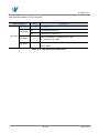
VH GigE Series
Active Image (H × V)
Sensor Type
Pixel size
Sensor Output
VH-5MG2
VH-11MG2
VH-16MG2
2448 × 2056
4008 × 2672
4872 × 3248
Sony
Truesense Imaging
Truesense Imaging
ICX625
KAI-11002
KAI-16000
3.45 ㎛ × 3.45 ㎛
9.0 ㎛ × 9.0 ㎛
7.4 ㎛ × 7.4 ㎛
2 Tap
1 or 2 Tap
Video Output
8/10/12 bits
> 52 ㏈
Dynamic Range
> 64 ㏈
Mono
Mono8, Mono10, Mono10 packed, Mono12, Mono12 packed
Color
Bayer8, Bayer10, Bayer10 packed, Bayer12, Bayer12 packed
Output Format
Camera Interface
Gigabit Ethernet
Electronic Shutter
Global Shutter
Max. Frame Rate at Full Resolution
16 fps
Pixel Clock
60 ㎒
Shutter Speed (10 ㎲ step)
3.4 / 6.4 fps
2.2 / 4.2 fps
30/40 ㎒
29 ㎲ ~ 7s
131 ㎲ ~ 7s
209 ㎲ ~ 7s
Partial Scan (Max. Speed)
41 fps at 256 Lines
27 fps at 334 Lines
15 fps at 406 Lines
Binning
×1, ×2, ×3, ×4, ×8 (Horizontal and Vertical Independent)
Lookup Table
G=1.0, User Defined Lookup Table (LUT)
Black Level
Adjustable (0 ~ 127 LSB at 12 bit, 256 steps)
Analog Gain
×1 ~ ×40 (0 ~ 32 ㏈)
Exposure Mode
Timed Exposure, Trigger Width Exposure, Double Exposure
Auto Control
Auto Exposure, Auto Gain Control
(Only available on VH-5MG2)
External Trigger
3.3 V ~ 24.0 V, 10 ㎃, Asynchronous, optically isolated
Software Trigger
Asynchronous, Programmable via Camera API
Camera Image Memory
Lens Mount
Power
Environmental
Mechanical
128 MB
C-mount or F-mount
F-mount
10~15 V DC, Max. 6W
10~15 V DC, Max. 10W
Operating: -5℃ ~ 40℃, Storage: -40℃ ~ 70℃
68 ㎜ × 68 ㎜ × 54 ㎜, 395 g (with C-mount)
68 ㎜ × 68 ㎜ × 83 ㎜, 430 g (with F-mount)
Table 5.2 Specifications of VH GigE Series (VH-5/11/16MG2)
12 of 105
RA14-131-018
VH GigE series
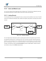
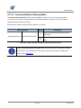
5.3
Camera Block Diagram
Ext.trigger
Line Driver
Prog.output
FPGA
DDR2
Image Processing
Control Logic
SDRAM
V Driver
CCD
Sensor
Optocoupler
ADC
(14bit)
Micro Controller
H Driver
Ethernet
Controller
FLASH
Network
EEPROM
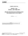
Figure 5.1 Camera Block Diagram
All controls and data processing of VH GigE cameras are carried out in one FPGA chip. The FPGA generally
consists of a 32 bit RICS Micro-Controller and Processing & Control Logic. The Micro-Controller receives
commands from the user through the Gigabit Ethernet interface and then processes them. The FPGA controls
the Timing Generators (TGs) and the Analog Front End (AFE) chips where the TGs generate CCD control
signals and AFE chips convert analog CCD output to digital values to be accepted by the Processing & Control
Logic. The Processing & Control Logic processes the image data received from AFE and then transmits data
through the Gigabit Ethernet interface. And also, the Processing & Control Logic controls the trigger input and
output signal which are sensitive to time. Furthermore, DDR2 for operating Micro-Controller and for used as
Gigabit Ethernet frame buffer, SDRAM for used as a frame buffer to process images, Gigabit Ethernet Controller
and Flash memory for saving system codes and defect coordinates are installed outside FPGA.
13 of 105
RA14-131-018
VH GigE series
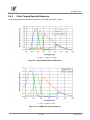
5.4
Spectral Response
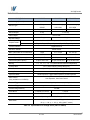
5.4.1
Mono Camera Spectral Response
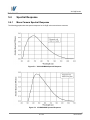
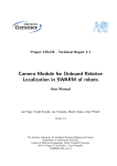
The following graphs show the spectral response for VH GigE series monochrome cameras.
Figure 5.2 VH-310G2-M264 Spectral Response
Figure 5.3 VH-2MG2-M42 Spectral Response
14 of 105
RA14-131-018
VH GigE series
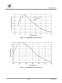
Figure 5.4 VH-4MG2-M20 Spectral Response
Figure 5.5 VH-5MG2-M16 Spectral Response
15 of 105
RA14-131-018
VH GigE series
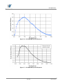
Figure 5.6 VH-11MG2-M6 Spectral Response
Figure 5.7 VH-16MG2-M4 Spectral Response
16 of 105
RA14-131-018
VH GigE series
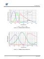
5.4.2
Color Camera Spectral Response
The following graphs show the spectral response for VH GigE series color cameras.
Figure 5.8 VH-310G2-C264 Spectral Response
Figure 5.9 VH-2MG2-C42 Spectral Response
17 of 105
RA14-131-018
VH GigE series
Figure 5.10 VH-4MG2-C20 Spectral Response
Figure 5.11 VH-5MG2-C16 Spectral Response
18 of 105
RA14-131-018
VH GigE series
Figure 5.12 VH-11MG2-C6 Spectral Response
Figure 5.13 VH-16MG2-C4 Spectral Response
19 of 105
RA14-131-018
VH GigE series
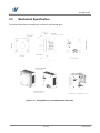
5.5
Mechanical Specification
The camera dimensions in millimeters are as shown in the following figure.
Figure 5.14 VH GigE Series C-mount Mechanical Dimension
20 of 105
RA14-131-018
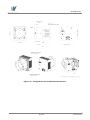
VH GigE series
Figure 5.15 VH GigE Series F-mount Mechanical Dimension
21 of 105
RA14-131-018
VH GigE series
Figure 5.16 VH-310G2 C-mount Mechanical Dimension
22 of 105
RA14-131-018
VH GigE series
6
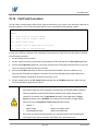
Software Licensing Information
The software in VH GigE series includes the lightweight IP (lwIP) TCP/IP implementation. The software licensing
information for this implementation is as follows.
Copyright (c) 2001-2004 Swedish Institute of Computer Science.
All rights reserved.
Redistribution and use in source and binary forms, with or without modification, are permitted provided
that the following conditions are met:
1.
Redistributions of source code must retain the above copyright notice, this list of conditions and
the following disclaimer.
2.
Redistributions in binary form must reproduce the above copyright notice, this list of conditions
and the following disclaimer in the documentation and/or other materials provided with the
distribution.
3.
The name of the author may not be used to endorse or promote products derived from this
software without specific prior written permission.
THIS SOFTWARE IS PROVIDED BY THE AUTHOR “AS IS” AND ANY EXPRESS OR IMPLIED
WARRANTIES, INCLUDING, BUT NOT LIMITED TO, THE IMPLIED WARRANTIES OF
MERCHANTABILITY AND FITNESS FOR A PARTICULAR PURPOSE ARE DISCLAIMED.
IN NO EVENT SHALL THE AUTHOR BE LIABLE FOR ANY DIRECT, INDIRECT, INCIDENTAL, SPECIAL,
EXEMPLARY, OR CONSEQUENTIAL DAMAGES (INCLUDING, BUT NOT LIMITED TO,
PROCUREMENT OF SUBSTITUTE GOODS OR SERVICES; LOSS OF USE, DATA, OR PROFITS; OR
BUSINESS INTERRUPTION) HOWEVER CAUSED AND ON ANY THEORY OF LIABILITY, WHETHER
IN CONTRACT, STRICT LIABILITY, OR TORT (INCLUDING NEGLIGENCE OR OTHERWISE) ARISING
IN ANY WAY OUT OF THE USE OF THIS SOFTWARE, EVEN IF ADVISED OF THE POSSIBILITY OF
SUCH DAMAGE.
23 of 105
RA14-131-018
VH GigE series
7
Connecting the Camera
The following instructions assume that you have installed an Ethernet Card including related software and
Vieworks Imaging Solution in your PC. For more information, refer to your Vieworks Imaging Solution
Installation Manual.
To connect the camera to your PC, follow the steps below:
1.
Make sure that the power supply is not connected to the camera and your PC is turned off.
2.
Plug one end of an Ethernet cable into the RJ45 jack on the camera and the other end of the Ethernet cable
into the Ethernet Card in your PC.
3.
Connect the plug of the power adaptor to the power input receptacle on the camera.
4.
Plug the power adaptor into a working electrical outlet.
5.
Verify all the cable connections are secure.
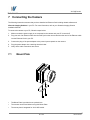
7.1
Mount Plate
The Mount Plate is provided as an optional item.
The camera can be fixed without using this Mount Plate.
The mount plate is integrated for VH-310G2 model.
24 of 105
RA14-131-018
VH GigE series
7.2
Precaution to Center the Image Sensor
Users do not need to center the image sensor as it is adjusted as factory default settings.
When you need to adjust the center of the image sensor, please contact your local dealer or the
manufacturer for technical assistance.
7.3
Precaution about Blurring Compared to Center
Users do not need to adjust the tilt as it is adjusted as factory default settings.
If the tilt settings need to be adjusted inevitably, please contact your local dealer or factory representative for
technical support.
7.4
Installing Vieworks Imaging Solution
You can download the Vieworks Imaging Solution at machinevision.vieworks.com.
You should perform the software installation first and then the hardware installation.
25 of 105
RA14-131-018
VH GigE series
8
Camera Interface
8.1
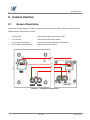
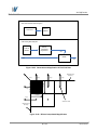
General Description
As shown in the following figure, 3 types of connectors and status indicator LED are located on the back of the
camera and have the functions as follows:
① Status LED:
displays power status and operation mode.
② RJ-45 Jack:
controls video data and the camera.
③ 4 pin Control Receptacle:
inputs external trigger signal and outputs strobe.
④ 6 pin Power Input Receptacle:
supplies power to the camera.
①
②
③
④
VH-310G2
Figure 8.1 VH GigE Series Back Panel
26 of 105
RA14-131-018
VH GigE series
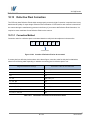
8.2
RJ-45 Jack
The 8-pin RJ-45 jack provides Ethernet access to the camera. Pin assignments for the RJ-45 jack adhere to the
Ethernet standard.
Figure 8.2 RJ-45 Jack
PAIR List
Pin
Signal Name
Type
Description
1
+TXA
Differential
Gigabit Ethernet Transceiver
2
-TXA
Differential
Gigabit Ethernet Transceiver
3
+TXB
Differential
Gigabit Ethernet Transceiver
6
-TXB
Differential
Gigabit Ethernet Transceiver
4
+TXC
Differential
Gigabit Ethernet Transceiver
5
-TXC
Differential
Gigabit Ethernet Transceiver
7
+TXD
Differential
Gigabit Ethernet Transceiver
8
-TXD
Differential
Gigabit Ethernet Transceiver
PAIR 0
PAIR 1
PAIR 2
PAIR 3
Table 8.1 Pin Assignments for the RJ-45 Jack
27 of 105
RA14-131-018
VH GigE series
8.3
Control Receptacle
The control receptacle is a Hirose 4 pin connector (part # HR10A-7R-4S) and consists of an external trigger
signal input and strobe output port. The pin assignments and configurations are as follows:
4
1
3
2
Figure 8.3 Pin Assignments for 4 Pin Control Receptacle
Pin Number
Signal
Type
Description
1
Trigger Input +
Input
Voltage difference of
2
Trigger Input -
Input
3
DC Ground
-
3.3 V ~ 24 V, 10 ㎃,
4
Programmable Output
Output
(Default: Strobe Out)
optically isolated
DC Ground
3.3 V TTL Output
Output resistance : 47 Ω
Table 8.2 Pin Arrangement of Control Receptacle
The mating connector is a Hirose 4 pin plug (part # HR10A-7P-4P) or the equivalent connectors.
28 of 105
RA14-131-018
VH GigE series
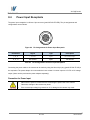
8.4
Power Input Receptacle
The power input receptacle is a Hirose 6 pin connector (part # HR10A-7R-6PB). The pin assignments and
configurations are as follows:
1
6
3
4
2
5
Figure 8.4 Pin Assignments for Power Input Receptacle
Pin Number
Signal
Type
Description
1, 2 , 3
+ 12V DC
Input
DC Power Input
4,5,6
DC Ground
Input
DC Ground
Table 8.3 Pin Configurations for Power Input Receptacle
Connecting the power cable to the camera can be made by using the Hirose 6 pin plug (part # HR10A-7P-6S) or
the equivalent. The power adaptor is recommended to have at least 1A current output at 12 V DC ±10% voltage
output (Users need to purchase the power adaptor separately).
Precaution for Power Input
Make sure the power is turned off before connecting the power cord to the camera.
Otherwise, damage to the camera may result.
If the camera input voltage is greater than 16 V, damage to the camera may result.
29 of 105
RA14-131-018
VH GigE series
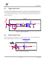
8.5
Trigger Input Circuit
The following figure shows trigger signal input circuit of the 4-pin connector. Transmitted trigger signal is applied
to the internal circuit through a photo coupler. Minimum trigger width that can be recognized by the camera is 1
㎲. If transmitted trigger signal is less than 1 ㎲, the camera will ignore the trigger signal. External trigger circuit
example is shown below.
+3.3~24.0V
Camera
Trigger
+5.0V
1K
PSD24C
HR10-7R-4SB
PSD24C
1
2
3
4
J-FET
Trigger+
47
180
Trigger_Input
2.2K
Trigger-
G ND
Your G ND
G ND
G ND
Figure 8.5 Trigger Input Schematic
8.6
Strobe Output Circuit
The strobe output signal comes out through a 3.3 V output level of Line Driver IC. You can change the strobe
output by setting the Digital IO Control (Refer to chapter 10.19 Digital IO Control).
Camera
+3.3V
+3.3V
5
0V
S trobe
47
4
2
3
1
2
3
4
5
6
47
S trobe_Output
Line Drive r
HR10-7R-6SB
Your G ND
G ND
G ND
Figure 8.6 Strobe Output Schematic
30 of 105
RA14-131-018
VH GigE series
9
Acquisition Control
This chapter provides detailed information about controlling image acquisition.
Triggering image acquisition
Setting the exposure time
Controlling the camera’s image acquisition rate
Variation of the camera’s maximum allowed image acquisition rate according to the camera settings
9.1
Overview
This section presents an overview of the elements involved with controlling the acquisition of images.
Three major elements are involved in controlling the acquisition of images:
Acquisition Start and Acquisition Stop commands and the Acquisition Mode parameter
The exposure start trigger
Exposure time control
When reading the explanations in the overview and in this entire chapter, keep in mind that
the term frame is typically used to mean a single acquired image.
Acquisition Start and Stop Commands and the Acquisition Mode
The Acquisition Start command prepares the camera to acquire frames. The camera cannot acquire frames
unless an Acquisition Start command has first been executed.
A parameter called the Acquisition Mode has a direct bearing on how the Acquisition Start command
operates.
If the Acquisition Mode parameter is set to Single Frame, you can only acquire one frame after executing an
Acquisition Start command. When one frame has been acquired, the Acquisition Start command will expire.
Before attempting to acquire another frame, you must execute a new Acquisition Start command.
If the Acquisition Mode parameter is set to Continuous, an Acquisition Start command does not expire after
a single frame is captured. Once an Acquisition Start command has been executed, you can acquire as many
frames as you like. The Acquisition Start command will remain in effect until you execute an Acquisition Stop
command. Once an Acquisition Stop command has been executed, the camera will not be able to acquire
frames until a new Acquisition Start command is executed.
31 of 105
RA14-131-018
VH GigE series
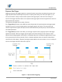
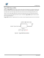
Exposure Start Trigger
Applying an exposure start trigger signal to the camera will exit the camera from the waiting for exposure start
trigger acquisition status and will begin the process of exposing and reading out a frame (see Figure 9.1). As
soon as the camera is ready to accept another exposure start trigger signal, it will return to the waiting for
exposure start trigger acquisition status. A new exposure start trigger signal can then be applied to the camera to
begin another frame exposure.
The exposure start trigger has two modes: off and on.
If the Trigger Mode parameter is set to Off, the camera will generate all required exposure start trigger signals
internally, and you do not need to apply exposure start trigger signals to the camera. The rate at which the
camera will generate the signals and acquire frames will be determined by the way that you set several frame
rate related parameters.
If the Trigger Mode parameter is set to On, you must trigger exposure start by applying exposure start trigger
signals to the camera. Each time a trigger signal is applied, the camera will begin a frame exposure. When
exposure start is being triggered in this manner, it is important that you do not attempt to trigger frames at a rate
that is greater than the maximum allowed (There is a detailed explanation about the maximum allowed frame
rate at the end of this chapter.). Exposure start trigger signals applied to the camera when it is not in a waiting for
exposure start trigger acquisition status will be ignored.
Figure 9.1 Exposure Start Triggering
32 of 105
RA14-131-018
VH GigE series
Applying Trigger Signals
The paragraphs above mention "applying a trigger signal". There are two ways to apply an exposure start trigger
signal to the camera: via software or via external (commonly referred to as hardware).
To apply trigger signals via Software, you must set the Trigger Source parameter to Software. At that point,
each time a Trigger Software command is executed, the exposure start trigger signal will be applied to the
camera.
To apply trigger signals via External, you must set the Trigger Source parameter to External. At that point,
each time a proper electrical signal is applied to the camera, an occurrence of the exposure start trigger signal
will be recognized by the camera.
Exposure Time Control
When an exposure start trigger signal is applied to the camera, the camera will begin to acquire a frame.
A critical aspect of frame acquisition is how long the pixels in the camera’s sensor will be exposed to light during
the frame acquisition.
If the Trigger Source parameter is set to Software, a parameter called the Exposure Time will determine the
exposure time for each frame. At this point, you must set the Exposure Mode parameter to Timed.
If the Trigger Source parameter is set to External, there are two modes of operation: Timed and Trigger Width.
With the Timed mode, the Exposure Time parameter will determine the exposure time for each frame.
With the Trigger Width mode, the way that you manipulate the rise and fall of the external signal will determine
the exposure time. The Trigger Width mode is especially useful if you want to change the exposure time from
frame to frame.
33 of 105
RA14-131-018
VH GigE series
9.2
Acquisition Start/Stop Commands and Acquisition Mode
Executing an Acquisition Start command prepares the camera to acquire frames. You must execute an
Acquisition Start command before you can begin acquiring frames. Executing an Acquisition Stop command
terminates the camera’s ability to acquire frames. When the camera receives an Acquisition Stop command:
If the camera is not in the process of acquiring a frame, its ability to acquire frames will be terminated
immediately.
If the camera is in the process of acquiring a frame, the frame acquisition process will be allowed to finish
and the camera’s ability to acquire new frames will be terminated.
The camera’s Acquisition Mode parameter has three settings: Single Frame, Multi-Frame and Continuous.
The use of Acquisition Start and Acquisition Stop commands and the camera’s Acquisition Mode parameter
setting are related.
If the camera’s Acquisition Mode parameter is set to Single Frame, after an Acquisition Start command has
been executed, a single frame can be acquired. When acquisition of one frame is complete, the camera will
execute an Acquisition Stop command internally and will no longer be able to acquire frames. To acquire
another frame, you must execute a new Acquisition Start command.
If the camera’s Acquisition Mode parameter is set to Multi-Frame, after an Acquisition Start command has
been executed, exposure start can be triggered as many as specified by the Acquisition Frame Count
parameter. The camera will continue to react to exposure start trigger signals until the number of exposure start
trigger signals it has received is equal to the current Acquisition Frame Count parameter setting. At that point,
the Acquisition Start command will expire. Before attempting to acquire another frame, you must execute a
new Acquisition Start command.
With Single Frame or Multi-Frame Acquisition Mode, if you execute another Acquisition
Start command while the camera is in the process of acquiring a frame, an error may occur.
If the camera’s Acquisition Mode parameter is set to Continuous, after an Acquisition Start command has
been executed, exposure start can be triggered as desired. Each time an exposure start trigger is applied while
the camera is in a waiting for exposure start trigger acquisition status, the camera will acquire and transmit a
frame. The camera will retain the ability to acquire frames until an Acquisition Stop command is executed.
Once the Acquisition Stop command is received, the camera will no longer be able to acquire frames.
When the camera's Acquisition Mode is set to Single Frame, the maximum possible acquisition frame rate for
a given ROI cannot be achieved. This is true because the camera performs a complete internal setup cycle for
each single frame and because it cannot be operated with Trigger Overlap. To achieve the maximum possible
acquisition frame rate, set the Acquisition Mode to Continuous and Trigger Overlap to Readout.
34 of 105
RA14-131-018
VH GigE series
9.3
Exposure Start Trigger
The exposure start trigger is used to begin frame acquisition. Exposure start trigger signals can be generated
within the camera or may be applied externally as Software or External exposure start trigger signals. If an
exposure start trigger signal is applied to the camera, the camera will begin to expose a frame.
9.3.1
Trigger Mode
The main parameter associated with the exposure start trigger is the Trigger Mode parameter. The Trigger
Mode parameter for the exposure start trigger has two available settings: Off and On.
9.3.1.1
Trigger Mode = Off
When the Trigger Mode parameter is set to Off, the camera will generate all required exposure start trigger
signals internally, and you do not need to apply exposure start trigger signals to the camera.
With the Trigger Mode set to Off, the way that the camera will operate the exposure start trigger depends on the
setting of the camera’s Acquisition Mode parameter:
Single Frame: The camera will automatically generate a single exposure start trigger signal whenever it
receives an Acquisition Start command.
Multi-Frame:
The camera will automatically begin generating exposure start trigger signals as many as
specified by the Acquisition Frame Count parameter when it receives an Acquisition
Start command. The camera will continue to generate exposure start trigger signals until the
number of exposure start trigger signals it has received is equal to the current Acquisition
Frame Count parameter setting or until it receives an Acquisition Stop command.
With Single Frame or Multi-Frame Acquisition Mode, if you execute another Acquisition
Start command while the camera is in the process of acquiring a frame, an error may occur.
When the Acquisition Mode parameter is set to Multi-Frame, you must set the value of the
camera’s Acquisition Frame Count parameter. The value of the Acquisition Frame Count
can range from 1 to 255.
35 of 105
RA14-131-018
VH GigE series
Continuous:
The camera will automatically begin generating exposure start trigger signals when it
receives an Acquisition Start command. The camera will continue to generate exposure
start trigger signals until it receives an Acquisition Stop command.
Free Run
When you set the Trigger Mode parameter to Off and the Acquisition Mode parameter
to Continuous, the camera will generate all required trigger signals internally. When the
camera is set this way, it will constantly acquire images without any need for triggering by
the user. This use case is commonly referred as “free run”.
When you operate the camera in free run, you must set the Trigger Overlap parameter
to Readout to achieve optimal camera performance.
The rate at which the exposure start trigger signals are generated may be determined by the camera’s
Acquisition Frame Rate parameter:
If the parameter is set to a value less than the maximum allowed frame rate with the current camera settings,
the camera will generate exposure start trigger signals at the rate specified by the parameter setting.
If the parameter is set to a value greater than the maximum allowed frame rate with the current camera
settings, the camera will generate exposure start trigger signals at the maximum allowed frame rate.
Exposure Time Control with Trigger Mode = Off
When the Trigger Mode parameter is set to Off, the exposure time for each frame acquisition is determined by
the value of the camera’s Exposure Time parameter. For more information about the Exposure Time
parameter, see 9.4 Setting the Exposure Time.
36 of 105
RA14-131-018
VH GigE series
9.3.1.2
Trigger Mode = On
When the Trigger Mode parameter is set to On, you must apply an exposure start trigger signal to the camera
each time you want to begin a frame acquisition. The Trigger Source parameter specifies the source signal that
will act as the exposure start trigger signal.
The available settings for the Trigger Source parameter are:
Software: You can apply an exposure start trigger signal to the camera by executing a Trigger Software
command for the exposure start trigger on your computer.
External: You can apply an exposure start trigger signal to the camera by injecting an externally generated
electrical signal (commonly referred to as a hardware trigger signal) into the Control Receptacle pin 1 on the
camera.
If the Trigger Source parameter is set to External, you must also set the Trigger Activation parameter.
The available settings for the Trigger Activation parameter are:
Rising Edge: Specifies that a rising edge of the electrical signal will act as the exposure start trigger.
Falling Edge: Specifies that a falling edge of the electrical signal will act as the exposure start trigger.
Exposure Time Control with Trigger Mode = On
When the Trigger Mode parameter is set to On and the Trigger Source parameter is set to Software, the
exposure time for each frame acquisition is determined by the value of the camera’s Exposure Time parameter.
When the Trigger Mode parameter is set to On and the Trigger Source parameter is set to External, the
exposure time for each frame acquisition can be controlled with the Exposure Time parameter or it can be
controlled by manipulating the external trigger signal.
37 of 105
RA14-131-018
VH GigE series
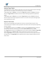
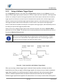
9.3.2
Using a Software Trigger Signal
If the Trigger Mode parameter is set to On and the Trigger Source parameter is set to Software, you must
apply a software trigger signal (exposure start) to the camera to begin each frame acquisition. Assuming that the
camera is in a waiting for exposure start trigger acquisition status, frame exposure will start when the software
trigger signal is received by the camera. Figure 9.2 illustrates frame acquisition with a software trigger signal.
When the camera receives a software trigger signal and begins exposure, it will exit the waiting for exposure
start trigger acquisition status because at that point, it cannot react to a new exposure start trigger signal.
As soon as the camera is capable of reacting to a new exposure start trigger signal, it will automatically return to
the waiting for exposure start trigger acquisition status.
When you are using a software trigger signal to start each frame acquisition, the camera’s Exposure Mode
parameter must be set to Timed. The exposure time for each acquired frame will be determined by the value of
the camera’s Exposure Time parameter.
When you use a software trigger signal to acquire frames, be aware that there is a Trigger
Latency due to the characteristics of the Gigabit Ethernet. Use an external trigger signal to
precisely synchronize the trigger signal with the exposure timing.
Figure 9.2 Frame Acquisition with Software Trigger Signal
When you are using a software trigger signal to start each frame acquisition, the frame rate will be
determined by how often you apply a software trigger signal to the camera, and you should not attempt to
trigger frame acquisition at a rate that exceeds the maximum allowed for the current camera settings.
(There is a detailed explanation about the maximum allowed frame rate at the end of this chapter.)
Software trigger signals that are applied to the camera when it is not ready to receive them will be ignored.
38 of 105
RA14-131-018
VH GigE series
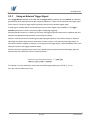
9.3.3
Using an External Trigger Signal
If the Trigger Mode parameter is set to On and the Trigger Source parameter is set to External, an externally
generated electrical signal injected into the Control Receptacle pin 1 will act as the exposure start trigger signal
for the camera. This type of trigger signal is generally referred to as a hardware trigger signal.
A rising edge or a falling edge of the external signal can be used to trigger frame acquisition. The Trigger
Activation parameter is used to select rising edge or falling edge triggering.
Assuming that the camera is in a waiting for exposure start trigger acquisition status, frame acquisition will start
whenever the appropriate edge transition is received by the camera.
When the camera receives an external trigger signal and begins exposure, it will exit the waiting for exposure
start trigger acquisition status because at that point, it cannot react to a new exposure start trigger signal. As
soon as the camera is capable of reacting to a new exposure start trigger signal, it will automatically return to the
waiting for exposure start trigger acquisition status.
When the camera is operating under control of an external signal, the period of the external trigger signal will
determine the rate at which the camera is acquiring frames:
For example, if you are operating a camera with an External trigger signal period of 500 ㎳ (0.5 s):
So in this case, the frame rate is 2 fps.
39 of 105
RA14-131-018
VH GigE series
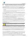
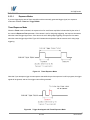
9.3.3.1
Exposure Modes
If you are triggering the start of frame acquisition with an externally generated trigger signal, two exposure
modes are available: Timed and Trigger Width.
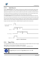
Timed Exposure Mode
When the Timed mode is selected, the exposure time for each frame acquisition is determined by the value of
the camera’s Exposure Time parameter. If the camera is set for rising edge triggering, the exposure time starts
when the external trigger signal rises. If the camera is set for falling edge triggering, the exposure time starts
when the external trigger signal falls. Figure 9.3 illustrates timed exposure with the camera set for rising edge
triggering.
Figure 9.3 Timed Exposure Mode
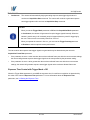
Note that if you attempt to trigger a new exposure start while the previous exposure is still in progress, the trigger
signal will be ignored, and an Over-trigger event will be generated.
Figure 9.4 Trigger Overlapped with Timed Exposure Mode
40 of 105
RA14-131-018
VH GigE series
Trigger Width Exposure Mode
When the Trigger Width exposure mode is selected, the length of the exposure for each frame acquisition will
be directly controlled by the external trigger signal. If the camera is set for rising edge triggering, the exposure
time begins when the external trigger signal rises and continues until the external trigger signal falls. If the
camera is set for falling edge triggering, the exposure time begins when the external trigger signal falls and
continues until the external trigger signal rises. Figure 9.5 illustrates Trigger Width exposure with the camera
set for rising edge triggering.
Trigger Width exposure is especially useful if you intend to vary the length of the exposure time for each frame.
Figure 9.5 Trigger Width Exposure Mode
41 of 105
RA14-131-018
VH GigE series
9.3.3.2
Double Exposure
When the Double Exposure mode is selected, two frames can be acquired in rapid succession using a single
trigger signal. The exposure time for the first frame begins according to the current camera settings when the
trigger signal is applied to the camera. Once the exposure for the first frame is complete, the camera reads out
the sensor data. At this point, the exposure time for the second frame begins. Then, the camera reads out the
sensor data for the second frame after reading out the sensor data for the previous frame.
In the Double Exposure mode, the exposure time for the second frame equals to the readout time of the first
frame. There is a just few microseconds (or dozen of microseconds) between the point where the exposure time
for the first frame ends and the point where the exposure time for the second frame begins. This is because the
camera cannot react to the exposure start trigger signal while reading out the sensor data for the first frame. At
this point, the camera outputs a strobe out signal reflected the exposure time for the first frame.
Figure 9.6 Double Exposure
9.3.4
Trigger Delay
The Trigger Delay feature specifies a delay (in microseconds) that will be applied between the receipt of a trigger
signal (software or external) and when the trigger will become effective.
The Trigger Delay can be specified in the range from 0 to 10,000,000 ㎲ (equivalent to 10 s).
The Trigger Delay will not operate if the Trigger Mode parameter is set to Off.
42 of 105
RA14-131-018
VH GigE series
9.4
Setting the Exposure Time
This section describes how the exposure time can be adjusted manually by setting the value of the exposure
time parameter.
Manual adjustment of the exposure time parameter will only work correctly if the Exposure
Auto feature is disabled.
If you are operating the camera in any one of the following ways, you must specify an exposure time by setting
the camera’s Exposure Time parameter:
the Trigger Mode is set to off
the Trigger Mode is set to On and the Trigger Source is set to Software (In this case, you must set the
Exposure Mode parameter to Timed.)
the Trigger Mode is set to On, the Trigger Source is set to External, and the Exposure Mode is set to
Timed.
The Exposure Time parameter must not be set below a minimum specified value. The Exposure Time
parameter sets the exposure time in ㎲. The minimum and maximum exposure time settings for each camera
model are shown in the following table.
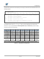
Camera Model
Minimum Allowed Exposure Time
VH-310G2
16 ㎲
VH-2MG2
37 ㎲
VH-4MG2
55 ㎲
VH-5MG2
29 ㎲
VH-11MG2
131 ㎲
VH16MG2
209 ㎲
Maximum Possible Exposure Time
†
7,000,000 ㎲
†: When the Exposure Mode is set to Trigger Width, the exposure time is controlled by the external trigger
signal and has no maximum limit.
Table 9.1 Minimum and Maximum Exposure Time Setting
43 of 105
RA14-131-018
VH GigE series
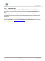
9.4.1
Exposure Auto
The Exposure Auto feature automatically adjusts the Exposure Time parameter within set limits until an
average gray value for the pixel data from the AE Data ROI reaches an Exposure Auto Target Level setting
value.
The Exposure Auto feature can be operated in the Once or Continuous modes of operation.
If the Data ROI does not overlap the Image ROI, the pixel data from the Data ROI will not be used to control the
exposure time.
The Exposure Auto feature and the Gain Auto feature can be used at the same time.
When the Trigger Width parameter is selected for Exposure Mode, the Exposure Auto feature is not available.
For more information, refer to 10.9 Exposure Auto and Gain Auto.
44 of 105
RA14-131-018
VH GigE series
9.5
Overlapping Exposure with Sensor Readout
The frame acquisition process on the camera includes two distinct parts. The first part is the exposure of the
pixels in the imaging sensor. Once exposure is complete, the second part of the process – readout of the pixel
values from the sensor – takes place. In regard to this frame acquisition process, there are two common ways
for the camera to operate: with Trigger Overlap – Off and with Trigger Overlap - Readout.
In the Trigger Overlap – Off mode of operation, each time a frame is acquired the camera completes the entire
exposure/readout process before acquisition of the next frame is started. The exposure for a new frame does not
overlap the sensor readout for the previous frame. Figure 9.7 illustrates the Trigger Overlap parameter set to
Off and the Exposure Mode parameter set to Trigger Width.
Figure 9.7 Trigger Overlap - Off
45 of 105
RA14-131-018
VH GigE series
In the Trigger Overlap – Readout mode of operation, the exposure of a new frame begins while the camera is
still reading out the sensor data for the previously acquired frame. Figure 9.8 illustrates the Trigger Overlap
parameter set to Readout and the Exposure Mode parameter set to Trigger Width.
Figure 9.8 Trigger Overlap - Readout
Determining whether your camera is operating with overlapped or non-overlapped exposure and readout is not a
matter of issuing a command or switching a setting on or off. Rather the way that you operate the camera will
determine whether the exposures and readouts are overlapped or not.
If we define the “Frame Period” as the time from the start of exposure for one frame acquisition to the start of
exposure for the next frame acquisition, then:
Non-overlapped:
Frame Period ≥ Exposure Time + Readout Time
Overlapped:
Frame Period ≤ Exposure Time + Readout Time
46 of 105
RA14-131-018
VH GigE series
Guidelines for Overlapped Exposure
If you will be operating the camera with overlapped exposure, there are two important guidelines to keep in mind:
You must not begin the exposure time for a new image acquisition while the exposure time of the previous
acquisition is in progress.
You must not end the exposure time of the current image acquisition until readout of the previously acquired
image is complete.
When you are operating a camera with overlapped exposure and using an external trigger signal to trigger
image acquisition, you could use the camera’s Exposure time parameter settings and timing formulas to
calculate when it is safe to begin each new acquisition.
The exposure must always begin on an interline boundary of the CCD sensor. For this
reason, if a trigger signal is applied during the readout process, there might be an Exposure
Start Delay up to 1 horizontal line time.
47 of 105
RA14-131-018
VH GigE series
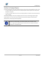
9.6
Real Exposure
9.6.1
Timed Exposure Mode
When the Timed mode is selected, the exposure time is determined by the time interval between the point
where an external trigger signal is applied and the point where the tpd (Photodiode Transfer) signal falls.
The camera generates a shutter signal to clear pixels when an external trigger signal is applied. The exposure
time begins when the shutter signal falls and continues until the tpd (Photodiode Transfer) signal falls. As Figure
9.9 shows, there is an Exposure Start Delay (refer to Table 9.3) between the rise of the external trigger signal
and the point where exposure actually begins. The setting value on the Exposure Time parameter is equal to
the exposure time, because the tsub value of the shutter signal and Transfer Pulse Offset value (tpd, t3p) are
compensated on the exposure time by the camera’s logic internally. Therefore, there is no difference between
the setting value on the Exposure Time parameter and the exposure time. The tsub value and Transfer Pulse
Offset value are determined by the CCD sensor used in the camera.
Figure 9.9 Real Exposure with Timed Exposure Mode
48 of 105
RA14-131-018
VH GigE series
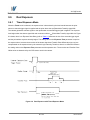
9.6.2
Trigger Width Exposure Mode
When the Trigger Width mode is selected, the exposure time is controlled by the external trigger signal.
The camera generates a shutter signal to clear pixels when an external trigger signal is applied. The exposure
time begins when the shutter signal falls and continues until the tpd (Photodiode Transfer) signal falls. As Figure
9.10 shows, there is an Exposure Start Delay (refer to Table 9.3) between the rise of the external trigger signal
and the rise of the shutter signal. There is difference between the width of the external trigger signal and the
exposure time as much as the tsub value of the shutter signal and Transfer Pulse Offset value (tpd, t3p).
You can calculate an actual exposure time by using the following formula:
Exposure Time = Trigger Width + t3p + tpd - tsub
Figure 9.10 Real Exposure with Trigger Width Exposure Mode
49 of 105
RA14-131-018
VH GigE series
The tsub and Transfer Pulse Offset value are determined by the CCD sensor used in the camera.
The following table shows the tsub and Transfer Pulse Offset values for VH GigE series.
Real Exposure Parameters
Model
Remarks
Exposure Start Delay
tsub
t3p
tpd
t3d
VH-310G2
0.7 ㎲
15 ㎲
0.4 ㎲
-
tsub: Shutter Transfer
VH-2MG2
3㎲
24 ㎲
12 ㎲
-
t3p: VCCD leading pedestal
VH-4MG2
3㎲
49 ㎲
5㎲
-
VH-5MG2
1㎲
20 ㎲
8.4 ㎲
-
VH-11MG2
3㎲
109 ㎲
20 ㎲
-
signal
Refer to Table 9.3
tpd: Photodiode transfer
signal
t3d: VCCD trailing pedestal
signal
VH-16MG2
4㎲
196 ㎲
12 ㎲
-
Exposure Start Delay: Trigger
Latency + Trigger Jitter
Table 9.2 Real Exposure Parameters
50 of 105
RA14-131-018
VH GigE series
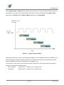
9.7
Acquisition Timing Chart
Figure 9.11 shows a timing chart for frame acquisition and transmission. The chart assumes that exposure is
triggered by an externally generated exposure start trigger signal, that the Trigger Activation parameter is set to
Rising Edge and that the Exposure Mode parameter is set to Timed.
As shown in the figure below, there is a slight delay between the rise of the exposure start trigger signal and the
start of exposure. After the exposure time for a frame acquisition is complete, the camera begins reading out the
acquired frame data from the imaging sensor into a frame buffer in the camera. When a sufficient amount of
frame data has accumulated in the frame buffer, the camera will begin transmitting the data to your computer.
This buffering technique avoids the need to exactly synchronize the clock used for sensor readout with the data
transmission. The camera will begin transmitting data when it has determined that it can safely do so without
over-running or under-running the buffer.
Exposure Start Delay:
the amount of time (including trigger jitter and latency) between the point
where the trigger signal rises and the point where exposure actually begins
Frame Readout time:
the amount of time it takes to read out the frame data from the imaging
sensor into the frame buffer
Frame Transmission time:
the amount of time it takes to transmit an acquired frame data from the
frame buffer in the camera to your computer
Transmission Start Delay:
the amount of time between the point where the camera begins reading out
the acquired frame data from the sensor and the point where it begins transmitting the acquired frame data
from the buffer to your computer
Figure 9.11 Timing Chart (not drawn to scale)
51 of 105
RA14-131-018
VH GigE series
The following table shows Exposure Start Delay for VH GigE series.
Exposure Start Delay
Model
Triggering during the Idle State
VH-310G2
2.2 ㎲ ± 0.02 ㎲
VH-2MG2
4.5 ㎲ ± 0.02 ㎲
VH-4MG2
4.5 ㎲ ± 0.02 ㎲
VH-5MG2
2.5 ㎲ ± 0.02 ㎲
VH-11MG2
4.5 ㎲ ± 0.02 ㎲
VH-16MG2
5.5 ㎲ ± 0.02 ㎲
Triggering during the Readout State
3.7 ㎲ ≤ Delay ≤ 19.1 ㎲ (1 Tap)
3.7 ㎲ ≤ Delay ≤ 12.2 ㎲ (2 Tap)
8.5 ㎲ ≤ Delay ≤ 40.4 ㎲ (1 Tap)
8.5 ㎲ ≤ Delay ≤ 24.0 ㎲ (2 Tap)
8.3 ㎲ ≤ Delay ≤ 49.8 ㎲ (1 Tap)
8.3 ㎲ ≤ Delay ≤ 28.7 ㎲ (2 Tap)
12.5 ㎲ ≤ Delay ≤ 55.8 ㎲ (1 Tap)
12.5 ㎲ ≤ Delay ≤ 34.7 ㎲ (2 Tap)
12.5 ㎲ ≤ Delay ≤ 113.4 ㎲ (1 Tap)
12.5 ㎲ ≤ Delay ≤ 62.5 ㎲ (2 Tap)
18.5 ㎲ ≤ Delay ≤ 141.1 ㎲ (1 Tap)
18.5 ㎲ ≤ Delay ≤ 78.8 ㎲ (2 Tap)
Based on the High Speed Pixel Clock (PclkSelector: PCLK1) except VH-5MG2 model (Normal Speed)
Table 9.3 Exposure Start Delay
The exposure must always begin on an interline boundary of the CCD sensor. For this
reason, if a trigger signal is applied during the readout process, there might be an Exposure
Start Delay up to 1 horizontal line time.
The transmission time can vary due to the characteristics of the Ethernet network.
And also, the transmission start delay can vary from frame to frame; however, it is very low significance when
compared to the transmission time.
52 of 105
RA14-131-018
VH GigE series
9.8
Maximum Allowed Frame Rate
In general, the maximum allowed acquisition frame rate on the camera may be limited by several factors:
The amount of time that it takes to transmit an acquired frame from the camera to your computer.
The amount of time needed to transmit a frame depends on the bandwidth assigned to the camera.
The setting for the Sensor Digitization Taps parameter. If this parameter is set for Two taps, you will be
able to acquire frames at a higher rate than if it is set to One tap.
The Binning feature. If binning is enabled, the maximum allowed frame rate will increase.
The amount of time it takes to read an acquired frame out of the imaging sensor and into the camera’s
frame buffer. This time varies depending on the setting for the Height parameter. Frames with a smaller
height take less time to read out of the sensor. The frame height is determined by the camera’s Height
settings (Image Format Control).
The exposure time for acquired frames. If you use very long exposure times, you can acquire fewer frames
per second.
Decreasing the Height parameter can increase the maximum allowed frame rate; however
the Width parameter does not affect the frame rate.
When the camera's Acquisition Mode is set to Single Frame, the maximum possible
acquisition frame rate for a given ROI cannot be achieved. This is true because the camera
performs a complete internal setup cycle for each single frame and because it cannot be
operated with Trigger Overlap – Readout mode.
To achieve the maximum possible acquisition frame rate, set the Acquisition Mode
parameter to Continuous and the Trigger Overlap parameter to Readout.
53 of 105
RA14-131-018
VH GigE series
9.8.1
Increasing the Maximum Allowed Frame Rate
You may find that you would like to acquire frames at a rate higher than the maximum allowed with the camera’s
current settings. In this case, you must adjust one or more of the factors that can influence the maximum allowed
frame rate and then check to see if the maximum allowed frame rate has increased:
The time that it takes to transmit a frame out of the camera is the main limiting factor on the frame rate. You
can decrease the frame transmission time (and thus increase the maximum allowed frame rate) by doing
one or more of the following:
Use an 8 bit pixel data format rather than a 12 bit pixel format. Images with fewer bits per pixel will take
less time to transmit.
Use a smaller ROI. Decreasing the ROI means that the camera has less data to transmit and therefore
the transmission time will decrease.
Use binning. When pixels are binned, there is less data to transmit and therefore the transmission time
will decrease.
Make sure that the Packet Size (GevSCPSPacketSize) parameter is set as high as possible for your
system and that the Inter-Packet delay (GevSCPD) parameter is set as low as possible.
If you have the Sensor Digitization Taps parameter set to One, consider changing the value to Two. This
will usually increase the maximum allowed frame rate.
If you are using normal exposure times and you are using the camera at its maximum resolution, your
exposure time will not normally restrict the frame rate. However, if you are using long exposure times or
small region of interest, it is possible that your exposure time is limiting the maximum allowed frame rate. If
you are using a long exposure time or a small ROI, try using a shorter exposure time and see if the
maximum allowed frame rate increases. (You may need to compensate for a lower exposure time by using a
brighter light source or increasing the opening of your lens aperture.)
An important thing to keep in mind is a common mistake new camera users frequently make
when they are working with exposure time. They will often use a very long exposure time
without realizing that this can severely limit the camera’s maximum allowed frame rate. As an
example, assume that your camera is set to use a 1 second exposure time. In this case,
because each frame acquisition will take at least 1 second to be completed, the camera will
only be able to acquire a maximum of one frame per second. Even if the nominal maximum
frame rate of VH-16MG2 model is, for example, 4.2 frames per second, it will only be able to
acquire one frame per second because the exposure time is set much higher than normal.
54 of 105
RA14-131-018
VH GigE series
10 Camera Features
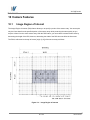
10.1
Image Region of Interest
The Image Region of Interest (ROI) feature allows you to specify a portion of the sensor array. You can acquire
only the frame data from the specified portion of the sensor array while preserving the same quality as you
acquire a frame from the entire sensor array. With the ROI feature, you can achieve increased frame rates by
decreasing the height of the ROI; however, decreasing the width of the ROI does not affect the frame rate.
The ROI is referenced to the top left corner [origin (0, 0)] of the sensor array as follows.
Figure 10.1 Image Region of Interest
55 of 105
RA14-131-018
VH GigE series
The XML parameters related to ROI settings are as follows.
XML Parameters
Value
SensorWidtha
SensorHeight
a
WidthMaxb
ImageFormatControl
HeightMax
b
c
Width
Description
-
Effective width of the sensor
-
Effective height of the sensor
-
-
Maximum allowed width of the image with the current
camera settings
Maximum allowed height of the image with the
current camera settings
-
Current width of the image
-
Current height of the image
b, d
-
Horizontal offset from the origin to the Image ROI
b, d
-
Vertical offset from the origin to the Image ROI
c
Height
OffsetX
OffsetY
The unit for all parameters in this table is pixel
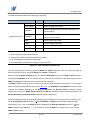
a: Read only. User cannot change the value
b: Changes and updates according to the Binning settings
c: User configurable parameters for settings ROI
d: User configurable parameters for setting the origin of the ROI
Table 10.1 XML parameters related to ROI
You can change the size of ROI by setting the Width and Height parameters. And also, you can change the
position of the ROI origin by setting the Offset X and Offset Y parameters.
Make sure that the Width + Offset X value is less than the Width Max value, and the Height + Offset Y value is
less than the Height Max value. You must set the size of the ROI first, and then set the Offset values since the
Width and Height parameters are set to its maximum value by default.
The Width parameter must be set to a multiple of 4, and the Height parameter must be set to a value greater
than the minimum Vertical ROI size shown in the Table 10.2. The Width Max and Height Max parameters will be
changed and updated depending on the Binning Horizontal and Binning Vertical parameter settings
respectively. And also, the Width, Height, Offset X and Offset Y parameters will be updated depending on the
Binning Horizontal and Binning Vertical parameter settings respectively.
ROI Size updated according to the Binning settings may not be restored to its original value. For example, if you
set the Binning Horizontal parameter to ×3 with 500 Width, the Width parameter will be updated to 166
automatically. Then, if you set the Width parameter to 166 and the Binning Horizontal parameter to ×1, the
Width parameter will be 498 (166 × 3). If you want to restore the Width to its original value, you can set the
Width to 500 manually.
56 of 105
RA14-131-018
VH GigE series
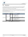
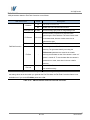
The approximate maximum frame rate depending on the change of Vertical ROI can be obtained as shown in the
following expression.
1 or 2 Channel Mode:
Frame Rate (fps) = 1000000 / [TVCCD + TRF × {VSIZE – (VROI + 12)} + (VROI + 12) × TL]
TVCCD : the amount of time required to transmit electric charges accumulated on
the pixels to Vertical Register
TRF
: the amount of time required for 1 row flush
VSIZE : the number of Vertical Line of CCD
TL
: the amount of time required for transmission of one line
VROI
: size of the Vertical ROI
The available minimum value of TVCCD, TRF, VSIZE, TL and VROI may vary depending on the camera model.
The value of TL may vary depending on the Sensor Digitization Taps and Pclk Selector parameter settings.
The values of each item are shown below.
VH GigE Series
VH-310G2
VH-2MG2
VH-4MG2
VH-5MG2
VH11MG2
VH-16MG2
TVCCD
30.4 ㎲
97 ㎲
11.6 ㎲
29.6 ㎲
210 ㎲
292 ㎲
TL (1 channel)
14.6 ㎲
35.9 ㎲
45.3 ㎲
-
108.9 ㎲
136.6 ㎲
TL (2 channel)
7.7 ㎲
19.5 ㎲
24.2 ㎲
30.6 ㎲
58.0 ㎲
74.3 ㎲
TRF
0.46 ㎲
3.0 ㎲
2.8 ㎲
9.0 ㎲
7.0 ㎲
12.0 ㎲
VSIZE
492 Lines
1216 Lines
2072 Lines
2068 Lines
2721 Lines
3324 Lines
60 Lines
150 Lines
256 Lines
256 Lines
334 Lines
406 Lines
Minimum
Vertical ROI
Based on the High Speed Pixel Clock (PclkSelector: PCLK1) except VH-5MG2 model (Normal Speed)
Table 10.2 Timing Value for VH GigE Series
57 of 105
RA14-131-018
VH GigE series
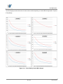
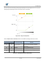
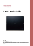
The following figure shows frame rate for each camera model depending on Vertical ROI changes with 1 Tap and
2 Tap settings.
Figure 10.2 Frame Rate by Vertical ROI changes
58 of 105
RA14-131-018
VH GigE series
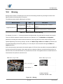
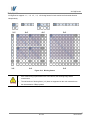
10.2
Binning
Binning has the effects of increasing the level value and decreasing resolution by summing the values of the
adjacent pixels and sending them as one pixel.
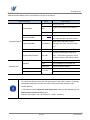
The XML parameters related to Binning are as follows.
XML Parameters
Value
BinningHorizontal
ImageFormatControl
BinningVertical
Description
×1, ×2, ×3,
Number of horizontal pixels to combine
×4, ×8
together
×1, ×2, ×3,
×4, ×8
Number of vertical pixels to combine together
Table 10.3 XML Parameters related to Binning
For example, if you set 2 × 2 binning as shown in the figure below, four pixels will be summed into one pixel.
Then, the effective maximum resolution of the sensor is reduced to 1/2. The Width Max and Height Max
parameters, indicating the maximum allowed resolution of the image with the current camera settings, will be
updated depending on the binning settings. And also, the Width, Height, Offset X and Offset Y parameters will
be updated depending on the binning settings. You can verify the current resolution through the Width and
Height parameters.
Since vertical binning is processed in the internal register of CCD, the frame rate will be increased and SNR will
be improved because the number of the readout process is reduced. However, the horizontal binning does not
affect the frame rate and SNR because it is processed in the FPGA. The brightness will be increased about four
times because four pixels are summed as one.
Figure 10.3 Binning
59 of 105
RA14-131-018
VH GigE series
VH GigE series supports ×1, ×2, ×3, ×4, ×8 binning factors for both vertical and horizontal direction
independently.
Figure 10.4 Binning factors
Even if the binning is performed on the color camera, the resulting image will be
monochrome.
The odd number of binning factor (×3) does not supported on the color camera due to
the characteristics of Bayer pattern.
60 of 105
RA14-131-018
VH GigE series
10.3
Sensor Tap Settings
With two taps sensor digitization, two (left and right) video amplifiers are used to output the charges moved to
the horizontal register during reading out the accumulated charges. Charges from the left half of the sensor are
shifted towards the Video L and charges from the right half of the sensor are shifted towards Video R.
Bottom Dark Rows
B
G
B
G
G
R
G
R
Bottom Buffer Rows
B
G
R
G
R
Active Pixels
B
G
B
G
G
R
G
R
Right Dark Columns
Left Dark Columns
Right Buffer Columns
G
G
Left Buffer Columns
B
Video L
B
G
G
R
Top Buffer Rows
Top Dark Rows
Horizontal Register
B
G
G
R
Rigth Dummy Pixels
Left Dummy Pixels
(1, 1)
Video R
One Tap
Two Taps
Figure 10.5 Two Taps Sensor Digitization
61 of 105
RA14-131-018
VH GigE series
XML parameters related to Sensor Tap Settings are as follows.
XML Parameters
ImageFormatControl
Value
Description
One
Set the Sensor Readout mode to 1 tap
Two
Set the Sensor Readout mode to 2 tap
SensorDigitizationTaps
Table 10.4 XML Parameter related to Sensor Tap Settings
When you set the Sensor Digitization Taps parameter to One, only the left video amplifier (Video L) will be
used to output the video data as shown in the Figure 10.8. And when you set the Sensor Digitization Taps
parameter to Two, both Video L and Video R will be used to output the video data as shown in the Figure 10.9.
When LVDS signals converted from the video data through ADC are transmitted to FPGA, the signal data will be
stored in the line buffer of FPGA until the transmission of one horizontal line is completed. Figure 10.10 and
10.11 show the structure which reorders and stores one line video data in the line buffer of FPGA according to
the one tap and two taps settings. After completing one line transmission, the data goes through image
processing. Then, the data will be reordered according to the Pixel Format parameter setting value and stored
in the frame buffer.
Video L
ADC
LVDS
CCD
FPGA
Image
Processing
&
Reorder
Frame
Buffer
GigE
Frame
Buffer
GigE
Figure 10.6 1Tap Image Data Flow
Video L
ADC
LVDS
CCD
Video R
ADC
LVDS
FPGA
Image
Processing
&
Reorder
Figure 10.7 2Taps Image Data Flow
62 of 105
RA14-131-018
VH GigE series
1 Line Buffer
Video L(N)
Video L(N+1)
Video L(N+2)
14-bit
14-bit
14-bit
Figure 10.8 1 Tap Reorder
1 Line Buffer
Video L
Video R
14-bit
14-bit
Figure 10.9 2 Tap Reorder
The LVDS video data converted in ADC are 14 bits, however the camera outputs 12 bits video data. The noise
performance will be improved on the output image by removing the 2 least significant bits.
MSB
LSB
D13 D12 D11 D10
D9
D8
D7
D6
D5
D4
D3
D2
D11 D10
D7
D6
D5
D4
D3
D2
D1
D0
D9
D8
D1
D0
Figure 10.10 12bit Conversion
63 of 105
RA14-131-018
VH GigE series
10.4
Pixel Format
The internal processing of image data is performed in 12 bits. Then, the camera can output the data in 8, 10 or
12 bits. When the camera outputs the image data in 8 bits or 10 bits, the 4 or 2 least significant bits will be
truncated accordingly.
MSB
LSB
Original
Data
D11 D10
D9
D8
D7
D6
D5
D4
D3
D2
D1
D0
12Bit Output
D11 D10
D9
D8
D7
D6
D5
D4
D3
D2
D1
D0
10Bit Output
D9
D8
D7
D6
D5
D4
D3
D2
D1
D0
8Bit Output
D7
D6
D5
D4
D3
D2
D1
D0
Figure 10.11 Pixel Format
The image data converted to 8, 10 or 12 bits support various pixel data format depending on the camera model.
The pixel data will be reordered in FPGA according to the Pixel Format setting value. Then, it will be stored in
the frame buffer before output. XML parameter related to the Pixel Format is as follows.
XML Parameters
ImageFormatControl
PixelFormat
Description
Set the pixel format supported by the device
Table 10.5 XML Parameter related to Pixel Format
64 of 105
RA14-131-018
VH GigE series
The supported pixel formats for monochrome and color cameras are as follows.
Mono Sensor
Color Sensor
Mono 8
Mono 8
Mono 10
Mono 10
Mono 10 Packed
Mono 10 Packed
Mono 12
Mono 12
Mono 12 Packed
Mono 12 Packed
Bayer GR (or RG) 8
Bayer GR (or RG) 10
Bayer GR (or RG) 12
Bayer GR (or RG) 10 Packed
Bayer GR (or RG) 12 Packed
Table 10.6 Pixel Data Format Value
The structures for supported pixel formats are as follows.
Mono 8
With the camera set to Mono 8, the pixel data output is 8 bit monochrome, unsigned char and unpacked type.
This type is stored in a byte unit when 8 bit pixel data are stored in the frame buffer.
Pixel Data
MSB
LSB
8-bit
7 6 5 4 3 2 1 0
Byte 0
Figure 10.12 Mono 8 Format
65 of 105
RA14-131-018
VH GigE series
Mono 10
With the camera set to Mono 10, the pixel data output is 10 bit monochrome, unsigned char and unpacked type.
This type is divided into two bytes when 10 bit pixel data are stored in the frame buffer. 8 bits of pixel data will be
stored in Byte 0, 2 bits of pixel data will be stored in Byte 1, and the rest 6 bits will not be used.
Pixel Data
MSB
LSB
X X X X X X
2-bit
8-bit
9 8
7 6 5 4 3 2 1 0
Byte 1
Byte 0
Figure 10.13 Mono 10 Format
Mono 10 Packed
With the camera set to Mono 10 Packed, the pixel data output is 10 bit monochrome, unsigned char and
GigE Vision-specific packed type.
This type is divided into three bytes when 20 bit pixel data are stored in the frame buffer. 8 bits of pixel data 0 will
be stored in Byte 0 and the rest 2 bits will be stored in Byte 1. Pixel Data 1 will be stored in Byte 2 and the rest 2
bits will be stored in Byte 1.
Pixel Data 1
Pixel Data 0
MSB
LSB
2-bit
8-bit
9 8 7 6 5 4 3 2
Byte 2
X X
1 0
X X
2-bit
8-bit
1 0
9 8 7 6 5 4 3 2
Byte 1
Byte 0
Figure 10.14 Mono 10 Packed Format
66 of 105
RA14-131-018
VH GigE series
Mono 12
With the camera set to Mono 12, the pixel data output is 12 bit monochrome, unsigned and unpacked type.
This type is divided into two bytes when 12 bit pixel data are stored in the frame buffer. 8 bits of pixel data will be
stored in Byte 0 and the rest 4 bits will be stored in Byte 1. The rest 4 bits of Byte 1 will not be used.
Pixel Data
MSB
LSB
X X X X
4-bit
8-bit
11 10 9 8
7 6 5 4 3 2 1 0
Byte 1
Byte 0
Figure 10.15 Mono 12 Format
Mono 12 Packed
With the camera set to Mono 12 Packed, the pixel data output is 12 bit monochrome, unsigned and
GigE Vision-specific packed type.
This type will be divided into three bytes when 24 bit pixel data are stored in the frame buffer.
8 bits of pixel data 0 will be stored in Byte 0 and the rest 4 bits will be stored in Byte 1. 8 bits of pixel data 1 will
be stored in Byte 2 and the rest 4 bits will be stored in Byte 1.
Pixel Data 0
Pixel Data 1
LSB
8-bit
11 10 9 8 7 6 5 4
Byte 2
4-bit
4-bit
8-bit
3 2 1 0
3 2 1 0
11 10 9 8 7 6 5 4
Byte 1
Byte 0
Figure 10.16 Mono 12 Packed Format
67 of 105
RA14-131-018
VH GigE series
Bayer Format
When you set the Pixel Format parameter to any Bayer Format in the color camera, the bits of pixel data will
be reordered to bytes, and then will be stored in the frame buffer in the same way as Mono Format.
For example, if you set the Pixel Format parameter to Bayer GR 10 Packed, the pixel data will be reordered
and stored in the frame buffer as shown in the Figure 10.17. 10 least significant bits of green data will be stored
in Byte 0 and Byte 1, and 10 most significant bits of red data will be stored in Byte 2 and Byte 1. The bit order is
shown in the first figure below. After saving 1 - horizontal line of G-R pattern pixel data, 2 – horizontal line of B-G
pattern pixel data will be stored as shown in the second figure below. G-R pattern (Horizontal Direction) and B-G
pattern (Horizontal Direction) pixel data will be stored repeatedly as a line (Vertical Direction).
Pixel Data (1,1)-Green
Pixel Data (2,1)-Red
MSB
LSB
8-bit
2-bit
2-bit
8-bit
9 8 7 6 5 4 3 2
X X 1 0
X X 1 0
9 8 7 6 5 4 3 2
1-Line
Byte 2
Byte 1
Byte 0
Pixel Data (0,1)-Green
Pixel Data (1,2)-Blue
MSB
2-Line
Horizontal
Direction
LSB
8-bit
2-bit
9 8 7 6 5 4 3 2
X X 1 0
Byte 2
2-bit
8-bit
X X 1 0
9 8 7 6 5 4 3 2
Byte 1
Byte 0
Vertical
Direction
Figure 10.17 Bayer Format
The alignment of the Bayer filter used in color cameras depends on the camera model. The filter alignment for
each available camera model is as follows.
Color Camera Model
Filter Alignment
VH-310G2, VH-2MG2, VH-4MG2, VH-11MG2,
VH-16MG2
GR
VH-5MG2
RG
Table 10.7 Bayer Filter Alignment
68 of 105
RA14-131-018
VH GigE series
10.5
Pixel Clock
VH GigE camera provides a unique way to control the camera speed and frame rate. You can select the pixel
clock to operate the camera either in Normal or High-speed (over-clocked) mode. With Normal mode, the
camera’s frame rate is determined by the CCD sensor manufacturer.
VH GigE camera internal design is optimized for High-speed mode. With High-speed mode, it is possible to overclock the camera which will result in higher frame rate. However, the camera signal to noise ratio (SNR) may be
reduced compared to Normal mode.
XML parameters related to pixel clock are as follows.
XML Parameters
Value
PCLK0
PclkSelector
DeviceControl
PCLK1
CurrentPclkFreq
-
Description
Set pixel clock to Normal mode
VH-11M/16MG2 – 30 ㎒
VH-310/2M/4MG2 – 40 ㎒
VH-5MG2 – 60 ㎒ (Only operate in Normal mode)
Set pixel clock to High-speed mode
VH-11M/16MG2
VH-310/2M/4MG2 – 50 ㎒
– 40 ㎒
Display the current camera pixel clock in ㎒
Table 10.8 XML Parameters related to Pixel Clock
69 of 105
RA14-131-018
VH GigE series
10.6
Stream Hold
VH GigE camera provides Stream Hold feature for controlling the transmission of data.
Normally, the camera transmits frame data to the host computer immediately after completing the exposure.
Enabling the Stream Hold feature delays the transmission of data, storing it in the camera’s volatile memory
until the Stream Hold feature is disabled.
This feature is especially useful to prevent flooding in Gigabit Ethernet network where multiple cameras are
connected to a single host computer and capture a single event. Using the Stream Hold feature, each camera
will hold the image data until the camera’s Stream Hold feature is disabled. VH GigE camera provides 128 MB
on-board memory for the Stream Hold feature. The Stream Hold feature does not allow you to select which
frame will be released to the host computer. When the Stream Hold feature is disabled, the stored frame data
will be released to the host computer. For more information, refer to the application note about stream hold.
XML Parameters
Value
On
Description
Delay the transmission of frame data and store them
in the frame buffer.
StreamHold
Off
Release the stored frame data to the host computer.
-
Display the maximum number of frames that you
can store in the frame buffer
TransportLayerControl
The maximum number of frames will vary
depending on the Image ROI and pixel format
FrameCapacity
settings.
With the Stream Hold feature set to On, the
newly acquired frame will be ignored after saving
the maximum number of frames.
Table 10.9 XML Parameters related to Stream Hold feature
70 of 105
RA14-131-018
VH GigE series
10.7
Inter-Packet Delay
VH GigE camera provides the Inter-packet delay feature to set the delay in ticks between the packets
transmitted by the camera.
Packet Size
The Gev SCPS Packet Size parameter sets the size of the packets that the camera will use when it sends the
data via the selected stream channel. This parameter should always be set to the maximum size that your
network components (Ethernet Adapter) can handle.
Setting the delay between packets
The Gev SCPD parameter sets the delay in ticks between the packets transmitted from the camera. Increasing
the delay will decrease the camera’s effective data transmission rate and will thus decrease the network
bandwidth used by the camera.
In the VH GigE camera, one tick is 8 ㎱. To check the tick frequency, read the Gev Time stamp Tick
Frequency parameter value.
In case of multiple cameras or other devices working on the same physical network, it might be desirable to send
the packets of a camera’s streaming channel with a certain inter-packet delay in order to allow multiple cameras
or devices to share a given network bandwidth.
XML Parameters
Value
Description
Set the packet size (The maximum
GevSCPSPacketSize
576~16,000 Bytes
TransportLayerControl
value may vary depending on the
Ethernet Adapter.).
GevSCPD
0~ TBD
Set the delay between packets.
Table 10.10 XML Parameters related to Inter-Packet Delay
71 of 105
RA14-131-018
VH GigE series
10.8
Data ROI
The Exposure Auto and Balance White Auto features use the pixel data from a Data Region of Interest (ROI)
to adjust the related parameters. XML parameters related to data ROI are as follows.
XML Parameters
Value
AE
RoiSelector
AWB
DataRoiControl
Description
Select a Data ROI used for Exposure Auto
Select a Data ROI used for Balance White Auto
Only available on the color camera
RoiOffsetX
-
X coordinate of start point ROI
RoiOffsetY
-
Y coordinate of start point ROI
RoiWidth
-
Width of ROI
RoiHeight
-
Height of ROI
Table 10.11 XML Parameters related to Data ROI
72 of 105
RA14-131-018
VH GigE series
Only the pixel data from the area of overlap between the data ROI by your settings and the Image ROI will be
effective if you use Image ROI and Data ROI at the same time. The effective ROI is determined as shown in the
figure below.
Figure 10.18 Effective Data ROI
73 of 105
RA14-131-018
VH GigE series
10.9
Exposure Auto and Gain Auto
The Exposure Auto feature automatically adjusts the Exposure Time parameter until the grey level for the
pixels in the given Data ROI reaches an Exposure Auto Target Level value set by the user.
The Exposure Auto feature in VH GigE series uses iterative algorithm which repeatedly calculates the previous
exposure values until it gets new exposure value. Note that the camera needs up to 30 frames to complete the
Exposure Auto feature.
The Exposure Auto feature is not available if the Exposure Mode parameter is set to
Trigger Width.
The Exposure Auto and Gain Auto features can be used at the same time and operated in the Off, Once and
Continuous modes of operation. If you use two features at the same time, the camera will adjust the value of
Exposure Time followed by Digital Gain.
When the Exposure Auto or Gain Auto feature is set to Once, the parameter values are automatically adjusted
until the related parameter value reaches the target value. After the automatic parameter value adjustment is
complete, the feature will be set to Off. When the auto feature is set to Continuous, the camera adjusts
Exposure Time or Digital Gain parameter to reach the target value every time the lighting conditions change. You
can set the Exposure Auto Tolerance parameter to adjust the sensitivity of the Exposure Auto feature.
Figure 10.19 Exposure Auto Target Level and Exposure Auto Tolerance
74 of 105
RA14-131-018
VH GigE series
Each auto feature has the following operating ranges depending on the object brightness level. You can set the
operating range by adjusting the minimum and maximum value for each feature.
Figure 10.20 Image Level Adjustment
When the Exposure Auto or Gain Auto parameter is set to Off, the operating procedures are as follow.
Auto Features
Operating Procedures
Remarks
Exposure
Gain
On
On
Exposure Gain
On
Off
Exposure
Manually adjustable the Gain
Off
On
Gain
Manually adjustable the Exposure
Off
Off
Both the Exposure and Gain are adjusted
automatically
Manually adjustable both the Exposure and
-
Gain
Table 10.12 Operating Procedures for Auto Features
75 of 105
RA14-131-018
VH GigE series
XML parameters related to AEC (Auto Exposure Control) are as follows.
XML Parameters
Value
Off
ExposureAuto
Once
ExposureAutoMin
Description
Exposure Auto Off
Target Level is adapted once and then
Off
Continuous
Target Level is constantly adapted
Refer to Table
Lower limits of Exposure duration
9.1
(The lower the value, the more smear)
AcquisitionControl
Upper limits of Exposure duration
~7,000,000 ㎲
ExposureAutoMax
(The higher the value, the more motion
blur)
ExposureAutoTargetLevel
100~3995
†
Target average grey value (12bit )
Tolerance of the target average grey
ExposureAutoTolerance
100~2047
value - 12 bit (If the current grey level is
out of the tolerance, AEC starts to work.)
GainAuto
AnalogControl
GainAutoMin
Off
Gain Auto Off
Once
Gain is adjusted once and then Off
Continuous
Gain is constantly adjusted
×1~×64
GainAutoMax
Lower limits of Gain
Upper limits of Gain
Table 10.13 XML Parameters related to AEC
You can set the Exposure Auto and Gain Auto feature in any order. However, we strongly
recommend setting the one feature first while turning off the other features for the
smooth operation.
†: The maximum allowed Exposure Auto Target Level value may vary depending on the
Exposure Auto Tolerance setting value.
Exposure Auto Target Level = (0+Tolerance) ~ (4,095 –Tolerance)
76 of 105
RA14-131-018
VH GigE series
10.10
Balance White Auto (Color Cameras)
The Balance White Auto feature is implemented on color cameras. It will control the white balance of the image
acquired from the color camera according to the GreyWorld algorithm. Before using the Balance White Auto
feature, you need to set the Data ROI for Balance White Auto. If you do not set the related Data ROI, the pixel
data from the Image ROI will be used to control the white balance. As soon as the Balance White Auto
parameter is set to Once, the Digital Red, Digital Green and Digital Blue will be set to 1. Then, Digital Red and
Digital Blue will be adjusted to control the white balance.
XML parameters related to the Balance White Auto and RGB Gain settings are as follows.
XML Parameters
GainSelector
AnalogControl
Value
AnalogAll
Apply gain to all analog taps
AnalogTap1
Apply analog gain to Tap1
AnalogTap2
Apply analog gain to Tap2
DigitalAll
Apply gain to all digital channel
DigitalRed
Apply gain to red digital channel
DigitalGreen
Apply gain to green digital channel
DigitalBlue
Apply gain to blue digital channel
×0.5 ~ ×2.0
Gain
Description
Set an absolute physical gain value when Digital
Red, Green or Blue is selected
Off
Balance White Auto Off
Once
White Balance is adjusted once and then Off
BalanceWhiteAuto
Table 10.14 XML Parameters related to Balance White Auto
77 of 105
RA14-131-018
VH GigE series
10.11
Gain and Black Level
You can set the analog (VGA) and digital gain factor to adjust the gain. The black level is adjusted by removing
the optical black offset from the CCD so that the effect of dark current will be minimized.
10.11.1 Analog Domain
The VH GigE camera has one Analog Signal Processor (or Analog Front End (AFE)) for each channel. This AFE
consists of Correlated Double Sampler (CDS), Variable Gain Amplifier (VGA), Black Level Clamp and 14-bit A/D
converter.
ANALOG
CCD IN
CDS
GAIN
VGA
GAIN
14-BIT
ADC
14-BIT
LVDS
1~40 times
LEVEL
CLAMP
Figure 10.21
AFE Block Diagram
You can change the gain and black level value by inputting proper value into the registers for gain and black
level adjustments inside the AFE. The CDS gain value is set in the factory during the manufacturing process,
therefore you cannot change the value. The VGA gain is the same as the analog gain. You can set the analog
gain for all analog taps or each tap. You can determine whether to control the gain balance between each tap
manually or automatically by setting the Gain Auto Balance parameter to Off or Once. To balance the black
level between each tap, use the Black Level parameter.
78 of 105
RA14-131-018
VH GigE series
10.11.2 Digital Domain
Digital gain is adjustable from 1 to 64 with almost 1/1024 step. If the Gain Auto parameter is set to Once or
Continuous, the digital gain value will be automatically adjusted according to the Exposure Auto Target Level
parameter settings. XML parameters related to Gain and Black Level are as follows.
XML Parameters
GainSelector
Value
Description
AnalogAll
Apply gain to all analog taps
AnalogTap1
Apply analog gain to Tap1
AnalogTap2
Apply analog gain to Tap2
DigitalAll
Apply gain to all digital channel
DigitalRed
Apply gain to red digital channel
DigitalGreen
Apply gain to green digital channel
DigitalBlue
Apply gain to blue digital channel
Set an absolute physical gain value.
Gain
AnalogControl
GainAuto
-
Analog All: ×1.0 ~ ×40
Analog Tap1, 2
†
Off
Gain Auto Off
Once
Gain value is adjusted once and then Off
Continuous
Gain value is constantly adjusted
Off
Gain Auto Balance Off
‡
GainAutoBalance
Gain Balance for each tap is adjusted once and
Once
then Off
BlackLevelSelector
BlackLevel
All
Apply black level to all taps
Tap1
Apply black level to Tap1
Tap2
Apply black level to Tap2
0~255
Set an absolute physical black level value.
(0 ~ 127 LSB @ 12bit)
†: Adjustable value range may vary depending on the camera set and camera model.
‡: The illumination must be of uniform intensity throughout the sensor when performing Gain Auto Balance.
Table 10.15 XML Parameters related to Gain and Black Level
79 of 105
RA14-131-018
VH GigE series
10.12
LUT
LUT (Lookup Table) converts original image values to certain level values.
Luminance
Since it is mapped one to one for each level value, 12-bit output can be connected to 12-bit input. LUT is in the
form of table that has 4096 entries between 0~4095 and VH GigE camera provides a non-volatile space for LUT
data storage. You can determine whether to apply LUT and which LUT to use. For more information about how
to download LUT to the camera, refer to Appendix B.
4096 entry
Lookup Table
12-bit Data
12-bit Data
Figure 10.22 LUT Block
LUT
4000
3500
Output Level
3000
2500
2000
1500
1000
500
0
0
500
1000
1500
2000
Input Level
2500
3000
3500
4000
Figure 10.23 LUT at Gamma 0.5
80 of 105
RA14-131-018
VH GigE series
XML parameters related to LUT are as follows.
XML Parameters
LUTSelector
Value
Description
Luminance
Luminance LUT
On
Activate the selected LUT
Off
Deactivate the selected LUT
LUTEnable
LUTControl
LUTIndex
-
LUTValue
-
Index of coefficient for verifying the LUT Value
Luminance: 0 ~ 4095
Output value of the current LUT corresponding to the input value
of LUT Index
Table 10.16 XML Parameters related to LUT
81 of 105
RA14-131-018
VH GigE series
10.13
Defective Pixel Correction
The CCD may have Defective Pixels which cannot properly react to the light. Correction is required since it may
deteriorate the quality of output image. Defective Pixel information of CCD used for each camera is entered into
the camera during the manufacturing process in the factory. If you want to add Defective Pixel information, it is
required to enter coordinate of new Defective Pixel into the camera.
10.13.1 Correction Method
Correction value for a defective pixel is calculated based on valid pixel value adjacent in the same line.
L3
L2
L1
R1
R2
R3
<Current Pixel>
Figure 10.24 Location of Defective Pixel to be corrected
If current pixel is a defective pixel as shown in the above figure, correction value for this pixel is obtained as
shown in the following table depending on whether surrounding pixel is defective pixel or not.
Adjacent Defective Pixel(s)
Correction value of Current Pixel
None
(L1 + R1) / 2
L1
R1
R1
L1
L1, R1
(L2 + R2 ) / 2
L1, R1, R2
L2
L2, L1, R1
R2
L2, L1, R1, R2
(L3 + R3) / 2
L2, L1, R1, R2, R3
L3
L3, L2, L1, R1, R2
R3
Table 10.17 Calculation of Defective Pixel Correction Value
82 of 105
RA14-131-018
VH GigE series
10.13.2 Correction Method in Binning Mode
The Defective Pixel Correction feature is also available even when 2×2 or 4×4 binning is enabled.
The correction value will be averaged based on four neighboring pixels during 2×2 binning and sixteen
neighboring pixels during 4×4 binning.
XML parameter related to Defective Pixel Correction is as follows.
XML Parameters
Value
On
ImageFormatControl
Description
Apply a downloaded defective pixel map to
the camera
DefectivePixelCorrection
Off
Disable the application of the defective pixel
map
Table 10.18 XML Parameter related to Defective Pixel Correction
To apply the Defective Pixel Correction feature, you must download a Defective Pixel Map
to the camera. For more information about how to download a Defective Pixel Map to the
camera, refer to Appendix A.
83 of 105
RA14-131-018
VH GigE series
10.14
Flat Field Correction
The Flat Field Correction feature improves the image uniformity when you acquire a non-uniformity image due to
external conditions. The Flat Field Correction feature can be summarized by the following equation:
IC = {(IR – IB) × M} / (IF – IB)
Where,
IC : Level value of corrected image;
IR : Level value of original image;
IB : Black offset value;
M : Average value of image after correction;
IF : Level value of Flat Field data.
In actual use conditions, generate a Flat Field data (IF) and perform the Flat Field Correction feature according
to the following procedures.
1.
Set the binning mode as desired.
2.
Set the number of frames to be acquired for generating the Flat Field data into the Ffc Frames parameter.
3.
Execute the Ffc Generate parameter. The series of frames will be averaged and scaled down to 1/16 pixel.
Then, the camera will generate the Flat Field data.
4.
Execute the Ffc Save parameter to save the generated Flat Field data in the non-volatile memory.
When the Flat Field data are applied for correction, the Flat Field data which were scaled down will be
enlarged via Bilinear Interpolation as shown in the Figure 10.26.
5.
Set the average value in the Ffc Target Level parameter and the Ffc Mode parameter to On. Then, the
Flat Field data will be applied to the camera.
Executing the Ffc Generate parameter will ignore the current camera settings and will
temporarily change the camera settings to operate under the following default conditions.
When the generation of the Flat Field data is completed, the original settings of the
camera will be restored. If the Trigger Mode parameter is set to On and the Trigger
Source parameter is set to Software, you must provide the number of trigger signals
equal to the current Acquisition Frame Count parameter setting.
OffsetX, Y:
0
Width, Height:
Maximum possible values
SensorDigitizationTaps:
Maximum possible taps
Every time you change the binning mode, you must generate the Flat Field data again.
FFC feature may not work correctly in VH-310G2 due to small sensor size.
84 of 105
RA14-131-018
VH GigE series
<Flat Field Calibration Block Diagram>
External
SDRAM
Scale Down
<Flat Fielding Block Diagram>
Bilinear
Interpolated
Magnification
External
SDRAM
<IF>
IR*M/IF
<IR>
<IC>
Figure 10.25 Generation and Application of Flat Field Data
Magnified Image
Boundary
copy
copy
copy
16 Pixel
copy
copy
16 Pixel
copy
Scale-Down Data
Magnified Image
Boundary
Figure 10.26 Bilinear Interpolated Magnification
85 of 105
RA14-131-018
VH GigE series
XML parameters related to Flat Field Correction are as follows.
XML Parameters
Value
Off
FfcMode
†
On
FfcTargetLevel
0~4095
Description
Flat Field Correction Off
Enable the Flat Field Correction feature
Set the average grey level for image background
Set the number of frames to be acquired when
FfcFrames
1,2,4,8,16
generating the Flat Field data. The more frames result
in the better data; however it takes more time to
generate the data.
FfcGenerate
-
FlatFieldCorrection
Generate the Flat Field data
Save the generated Flat Field data in the non-volatile
memory. The generated data by executing the
FfcGenerate parameter are saved in the volatile
FfcSave
-
memory and the data are lost if the camera is reset or if
power is turned off. To use the data after the camera is
powered on or reset, save them in the non-volatile
memory.
FfcLoad
-
Load the Flat Field data from the non-volatile memory
into volatile memory
†: If the current setting values for the Binning Horizontal and Binning Vertical parameters are different from
the setting values at the time when you generate the Flat Field data, the Flat Field Correction feature is not
available even if you set the Ffc Mode parameter to On.
Table 10.19 XML Parameters related to Flat Field Correction
86 of 105
RA14-131-018
VH GigE series
10.15
Temperature Monitor
A sensor chip is embedded in the camera to monitor the internal temperature.
XML parameter related to Device Temperature is as follows.
XML Parameters
DeviceControl
DeviceTemperature
Description
Display device temperature in Celsius
Table 10.20 XML Parameter related to Device Temperature
10.16
Status LED
A green LED is installed on the back panel of the camera to inform the operation status of the camera. LED
status and corresponding camera status are as follows:
Continuous ON:
operates in Trigger Off Mode.
Repeat ON for 0.5 seconds, OFF for 0.5 seconds:
operates in Trigger Mode.
Repeat ON for 1 second, OFF for 1 second:
outputs Test Image.
Repeat ON for 0.25 second, OFF for 0.25 second:
operates in Trigger Mode and outputs Test Image.
87 of 105
RA14-131-018
VH GigE series
10.17
Test Image
To check whether the camera operates normally or not, it can be set to output test images generated in the
camera, instead of the image data from the CCD. Three types of test images are available; image with different
value in horizontal direction (Grey Horizontal Ramp), image with different value in diagonal direction (Grey
Diagonal Ramp), and moving image with different value in diagonal direction (Grey Diagonal Ramp Moving).
XML parameters related to Test Image are as follows.
XML Parameters
ImageFormatControl
Value
TestImageSelector
Description
Off
Test Image Off
GreyHorizontalRamp
Set to Grey Horizontal Ramp
GreyDiagonalRamp
Set to Grey Diagonal Ramp
GreyDiagonalRampMoving
Set to Grey Diagonal Ramp
Moving
Table 10.21 XML Parameter related to Test Image
Figure 10.27 Grey Horizontal Ramp
88 of 105
RA14-131-018
VH GigE series
Figure 10.28 Grey Diagonal Ramp
Figure 10.29 Grey Diagonal Ramp Moving
The test image may look different because the region of the test image may vary depending
on the camera’s resolution.
89 of 105
RA14-131-018
VH GigE series
10.18
Reverse X
The Reverse X feature let you flip the image horizontally. This feature is available in all operation modes.
Figure 10.30 Original Image
Figure 10.31 Reverse X Image
On color models of the camera, when the Pixel Format parameter is set to Bayer and the
Reverse X feature is used, the alignment of the color filter will be changed.
90 of 105
RA14-131-018
VH GigE series
10.19
Digital IO Control
The pin number 3 of the control receptacle is designated as programmable output and can be operated in
various modes.
XML parameters related to Digital IO Control are as follows.
XML Parameters
Value
Description
On
Invert the output signal of the line
Off
Do not invert the output signal of the line
Off
Disable the line output
ExposureActive
Output pulse signals indicating the current exposure time
FrameActive
Output pulse signals indicating a frame readout time
StrobeOut
Output Exposure Active signals with Strobe Out Delay
PulseGenerator
Output user defined pulse signals
UserOutput
Output User Output signal set by User Output Value
On
Set the bit state of the line to High
Off
Set the bit state of the line to Low
LineInverter
LineSource
DigitalIO
Control
UserOutputValue
PulsePeriod
1~60,000,000
PulseWidth
0~60,000,000
StrobeOutDelay
0~65535
Set a pulse period in microseconds when the Line Source
is set to Pulse Generator
Set a pulse width in microseconds when the Line Source
is set to Pulse Generator
Set a delay in microseconds when the Line Source is set
to Strobe Out
Table 10.22 Digital IO Control
91 of 105
RA14-131-018
VH GigE series
The camera can provide a Strobe Out output signal. The signal goes high when the exposure time for each
frame acquisition begins and goes low when the exposure time ends as shown in Figure 10.32. This signal can
be used as a flash trigger and is also useful when you are operating a system where either the camera or the
object being imaged is movable. Typically, you do not want the camera to move during exposure. You can
monitor the Strobe Out signal to know when exposure is taking place and thus know when to avoid moving the
camera.
Figure 10.32 Strobe Out Signal (not drawn to scale)
10.20
Event Control
VH GigE camera provides an Event Notification feature. With the Event Notification feature, the camera can
generate an event and transmit a related event message to the PC whenever a specific situation has occurred.
The camera can generate and transmit events for the following type of situation:
The end of an exposure has occurred (Exposure End)
XML parameters related to Event Control are as follows.
XML Parameters
Value
Description
†
EventSelector
ExposureEnd
EventControl
Select which particular event to control
Exposure End event is only available
On
Enable the selected event notification
Off
Disable the selected event notification
Event Notification
TransportLayer
GevTimestampControlLatch
-
GevTimestampControlReset
-
Latch the current time stamp counter into
GevTimestampValue.
Control
Reset the time stamp counter to 0.
†: The event notification may be delayed depending on your network latency or network circumstances.
Table 10.23 XML Parameters related to Event Control
92 of 105
RA14-131-018
VH GigE series
10.21
Device User ID
You can input user defined information up to 16 bytes.
XML parameter related to Device User ID is as follow.
XML Parameters
DeviceControl
Description
DeviceUserID
Input user defined information (16 bytes)
Table 10.24 XML Parameter related to Device User ID
10.22
Device Reset
Reset the camera physically to power off and on. You must connect to the network because the camera will be
released from the network after reset. XML parameter related to Device Reset is as follows.
XML Parameters
DeviceControl
Description
DeviceReset
Reset the camera physically
Table 10.25 XML Parameter related to Device Reset
93 of 105
RA14-131-018
VH GigE series
10.23
User Set Control
You can save the current camera settings to the camera’s internal ROM. You can also load the camera settings
from the camera’s internal ROM. The camera provides two setups to save and three setups to load settings.
XML parameters related to User Set Control are as follows.
XML Parameters
UserSetSelector
UserSetLoad
Value
Description
Default
Select the Factory Default settings
UserSet1
Select the User Set1 settings
UserSet2
Select the User Set2 settings
-
UserSetControl
Load the User Set specified by User Set Selector
to the camera
Save the current settings to the User Set specified
UserSetSave
-
by User Set Selector
Default is allowed to load only.
UserSetDefaultSelector
Default
Apply the Factory Default settings when reset
UserSet1
Apply the User Set1 settings when reset
UserSet2
Apply the User Set2 settings when reset
Table 10.26 XML Parameters related to User Set Control
10.24
Field Upgrade
The camera provides a feature to upgrade Firmware and FGPA logic through Gigabit Ethernet interface rather
than disassemble the camera in the field. Refer to Appendix C for more details on how to upgrade.
94 of 105
RA14-131-018
VH GigE series
Appendix A Defective Pixel Map Download
1.
Create the Defective Pixel Map data in Microsoft Excel format as shown in the left picture below and save
as a CSV file (*.csv). The picture in the right shows the created Excel file opened in Notepad. The following
rules need to be applied when creating the file.
2.
Lines beginning with ‘:’ or ‘—‘ are treated as notes.
Each row is produced in the order of the horizontal and vertical coordinate values.
The input sequence of pixel is irrelevant.
Run Vieworks Imaging Solution 6.X and click the Configure button to display the window as shown below.
Select the Defect tab, click the File Path button, search and select the defective pixel map file (*.csv), and
then click the Download button.
95 of 105
RA14-131-018
VH GigE series
3.
Once the download is complete, the saving process will begin. During the saving process, make sure not to
disconnect the power cord.
4.
After completing the download, click the OK button to close the confirmation.
96 of 105
RA14-131-018
VH GigE series
Appendix B LUT Download
LUT data can be created in two ways; by adjusting the gamma values on the gamma graph provided in the
program and then downloading the data or by opening a CSV file (*.csv) and then downloading the data.
B.1
B.1.1
1.
Luminance LUT
Gamma Graph Download
Run Vieworks Imaging Solution 6.X and click the Configure button to display the window as shown below.
Select the LUT tab, and then select Luminance from the Type dropdown list.
2.
Set a desired value in the Gamma input field and click the Apply button.
97 of 105
RA14-131-018
VH GigE series
3.
Click the Download button to download the gamma set to the camera.
4.
After completing the download, click the OK button to close the confirmation.
98 of 105
RA14-131-018
VH GigE series
B.1.2
1.
CSV File Download
Create the LUT table in Microsoft Excel format as shown in the left picture below and save as a CSV file
(*.csv). The picture in the right shows the created file opened in Notepad. Once the file has been created
completely, change the .csv file extension to .lut. The following rules need to be applied when creating the
file.
2.
Lines beginning with ‘:’ or ‘—‘ are treated as notes.
Based on the input values, make sure to record from 0 to 4095.
Run Vieworks Imaging Solution 6.X and click the Configure button to display the window as shown below.
Select the LUT tab, select Luminance from the Type dropdown list, and then click the Load File button.
99 of 105
RA14-131-018
VH GigE series
3.
Search and select the created LUT file and click the Open button.
4.
Click the Download button. After completing the download, click the OK button to close the confirmation.
100 of 105
RA14-131-018
VH GigE series
Appendix C Field Upgrade
C.1
MCU
1.
Run Vieworks Imaging Solution 6.X and click the Configure button to display the window as shown below.
2.
Select the MCU tab, click the File Path button, search and select the MCU upgrade file (*.srec), and then
click the Download button.
3.
MCU upgrade file download starts and the downloading status is displayed at the bottom of the window.
101 of 105
RA14-131-018
VH GigE series
4.
Once all the processes have been completed, turn the power off and turn it back on again. Check the
DeviceVersion parameter value to confirm the version. Or, check under the My Computer to verify the
upgraded version.
102 of 105
RA14-131-018
VH GigE series
C.2
FPGA
1.
Run Vieworks Imaging Solution 6.X and click the Configure button to display the window as shown below.
2.
Select the FPGA tab, click the File Path button, search and select the FPGA upgrade file (*.bin), and then
click the Download button.
3.
The subsequent processes are identical to those of MCU upgrade.
103 of 105
RA14-131-018
VH GigE series
C.3
XML
1.
Run Vieworks Imaging Solution 6.X and click the Configure button to display the window as shown below.
2.
Select the XML tab, click the File Path button, search and select the XML upgrade file (*.xml), and then click
the Download button.
3.
The subsequent processes are identical to those of MCU upgrade.
104 of 105
RA14-131-018
Vieworks Co., Ltd.
#601-610 SuntechcityⅡ, 307-2 Sangdaewon-dong,
Jungwon-gu, Seongnam-si, Gyeonggi-do, 462-736 South Korea
Tel: +82-70-7011-6161 Fax: +82-31-737-4936
machinevision.vieworks.com
[email protected]