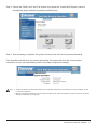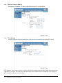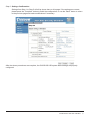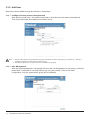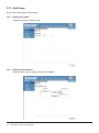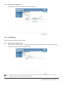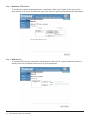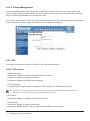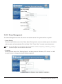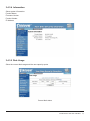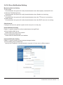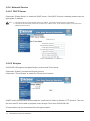
1
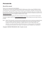
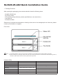
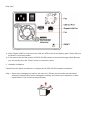
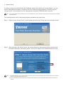
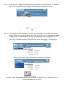
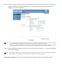
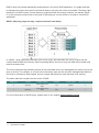
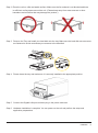
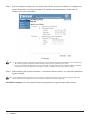
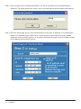
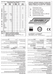
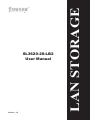
User Manual
Version : 1.0
LAN STORAGE
SL3620-2S-LB2
Forewords
About this manual
Thank you for using products from Stardom.
This manual will introduce the STARDOM SL3620-2S-LB2 products. Before using STARDOM SL36202S-LB2 products, you are advised to read this manual first. All information contained in this manual has
been carefully confirmed before printing, but the actual product specifications shall be in accordance with
those at the time of delivery; any update to product specifications or relevant information may be found on
www.stardom.com.tw, and no separate notification will be made.
If you have any query regarding the products of Raidon Technology, or you would like the latest product
information, please contact us at [email protected], and we shall give you a reply as soon as
possible.
Note : Raidon Technology will only provide technical support and services on products purchased directly
from the company. General consumers and third-party buyers who did not purchase from the
company should contact their distributor or supplier directly to receive faster support and
response. If you did not purchase products directly from our company, please avoid contacting
our company directly because your support and response may be delayed to your satisfaction.
Copyright © RAIDON TECHNOLOGY, INC. All rights reserved.
SL3620-2S-LB2 Quick Installation Guide
1. Package Contents
After opening the packaging, the contents should include the following items:
•SL3620-2S-LB2 Unit
•AC Power Cable
•CD (including setup software, product specifications, user manual etc.)
•User Manual
•Accessories Pack
Should any of the above accessories be missing or the main unit is damaged prior to initial use, please
contact your distributor or supplier.
Front View
Note : 1. If the disk formatting or array set up has been completed, do avoid switching the original position of the disks
2. Before changing to or removing a disk, make sure to turn off the power first. Do not remove the hard disk during power on,
otherwise, system failure will occur and any data stored may be lost.
Indicator LEDs
Power On
Status LED
Access LED
Flashes blue color
Flashes blue color
System Ready
Illuminates blue color
-
RAID Fail
Illuminates blue color
Flashing red color
Rebuilding
Flashes between blue & purplish colors
Fan Fail
Flashes between blue & purplish colors
-
Illuminates purplish color
-
Illuminates blue color
Flashes blue color
Over High Temperature
Access
Source : Flashes blue color
Target : Flashes between blue & purplish colors
Rear View
※ When Gigabit LAN Port connects to the LAN, the LED to the left will display green. When disk(s) is
accessed, it will display amber.
※ If the system fails and the product (SL3620-2S-LB2) cannot be accessed through a Web Browser,
you can directly press the “Reset” button to restart the system.
2. Hardware Installation
Please follow the below procedures to complete the SL3620-2S-LB2 hardware installation:
Step 1 Open outer packaging and retrieve the main unit. (Please check whether the associated
accessories and product itself is damaged or missing, and contact your distributor or sales
representative if you encounter any problems.)
Step 2 Place the unit on a flat and stable surface. Make sure the fan exhaust is not blocked and there
is sufficient cooling space around the unit. (Please keep away from water sources or other
hazardous environments that may damage the product.)
Step 3 Remove the Tray and install your hard disk onto the tray. Make sure the hard disk secure screws
are fastened to avoid unnecessary movements to the hard disk.
Step 4 Please insert the tray and make sure it is securely installed to the appropriate position.
Step 5 Connect the Gigabit LAN port and then plug in the power cable.
Step 6 Hardware installation is complete. You can power on the unit and perform the setup and
application preparations.
3. System Setup
To quickly configure the SL3620-2S-LB2 IP address, please first install the IP setup software. You can
use the “Management Software” included in the CD to install the setup software, or directly copy the
“Setup Util.exe” to the desktop from the “\Management Software\STARDOM NAS\” directory.
Note : If you do not install the setup software, the correct IP address may not be detected by the system and will become inaccessible
for configurations.
The following section we’ll be discussing software installation and instructions:
Step 1
Please run the “Setup Util.exe” on the desktop and click on the “Setup” button in the popup window.
Step 2
After clicking on the “Setup” button, the setup software will automatically find the product and
information as shown in the following screen. The server IP address can be obtained from this screen.
Note : 1. The total initialization of the unit from the time when the power is switched on takes about 2 minutes; prior to this, no device
will be found by the Network Storage Link.
2. If there are multiple SL3620-2S-LB2 units configured in the network, the panel to the left will list all devices found on the
network.
Step 3
Please enter the IP address obtained from Step2 in the web browser address bar. For example,
http://10.1.2.222, and the default username and the password are as shown below:
Login username: admin
Step 4
Default password: admin
If the hard disk has been formatted, the current system information will be shown and can be
properly configured. If two hard disks are being used, they have to be first formatted or prepared
for a RAID array. Go to “Maintenance” and select “Disk Utility” to format a single hard disk; or
select “RAID Setting” to create the RAID array. After formatting or setting up the RAID array, the
system will reboot and the system information will be shown after logging in. Please refer to
Chapter 3 for information on system configuration and formatting the hard disk.
If the hard disks installed have already been formatted, then relative information will be displayed as
shown above and the system configuration procedure may be started.
If the either one or both hard disks installed have not been formatted previously, then the system will
require the formatting of the disk(s).
Step 5 After the system is properly setup, please enter “Basic” and use the “Wizard” to configure the
system information, including Host Name, IP address, and password, etc. Please refer to
Chapter 3 for more information.
IP settings
Note : 1. Do not start the system configuration procedure if you have not already formatted the hard disk(s) or set up a RAID array.
All system configurations done prior to disk formatting and the set up of a RAID array may be lost.
2. If two or more SL3620-2S-LB2 units needs to be set up within a network, please be sure that the Host Name, IP address,
and password of each unit differs from one another for easier recognition and to avoid any system conflicts.
Step 6 After modifying the system information, it will reboot. After the reboot,
the system normally.
you may then operate
Note : If an IP address has been changed due to a new location, the browser would show “Cannot access webpage” after reboot.
Please enter the new IP address of the new location to the address bar to view the login page.
Installation complete. You can begin file sharing and personnel or group authorization set ups.
Contents
Chapter 1
1.1
1.2
1.3
Chapter 2
2.1
2.2
2.3
2.4
Chapter 3
3.1
3.2
3.3
3.3.1
3.3.2
3.3.3
3.3.4
3.4
3.4.1
3.4.1.1
3.4.1.2
3.4.2
3.4.2.1
3.4.2.2
3.4.3
3.4.3.1
3.4.3.2
3.4.3.3
3.4.3.4
3.4.3.5
3.4.3.6
3.4.4
3.4.4.1
3.4.4.2
3.4.4.3
3.4.5
3.4.5.1
3.4.5.2
3.4.5.3
3.4.5.4
3.4.5.5
3.4.5.6
3.4.6
Introduction to RAID................................................................................... 11
What is RAID?....................................................................................................... 11
RAID Functions...................................................................................................... 11
Comparison between RAID 0 and RAID 1............................................................ 11
Installation....................................................................................................... 13
Accessories........................................................................................................... 13
Hardware Installation............................................................................................. 14
Initial Setup............................................................................................................ 16
Modify System Information through the Software................................................. 19
Introduction to the User Interface....................................................... 23
User Interface Structure........................................................................................ 23
Login...................................................................................................................... 24
Basic...................................................................................................................... 28
Wizard.................................................................................................................... 28
Add User................................................................................................................ 32
Add Group.............................................................................................................. 34
Add Share.............................................................................................................. 35
Control Panel......................................................................................................... 37
Users and Groups.................................................................................................. 37
User Management................................................................................................. 37
Group Management ............................................................................................... 38
File......................................................................................................................... 38
File server.............................................................................................................. 38
Share Management ............................................................................................... 39
System................................................................................................................... 41
LAN Setting............................................................................................................ 41
Time Setting........................................................................................................... 42
Turn Off Server...................................................................................................... 42
Information............................................................................................................. 43
Disk Usage............................................................................................................ 43
Error Notification Setting........................................................................................ 45
Network Service..................................................................................................... 46
DHCP Server......................................................................................................... 46
Bonjour................................................................................................................... 46
BTorrent................................................................................................................. 47
Maintenance.......................................................................................................... 48
Disk Utility.............................................................................................................. 48
RAID Setting.......................................................................................................... 50
Firmware Upgrade................................................................................................. 50
Save Configuration................................................................................................ 51
Restore Configuration............................................................................................ 51
Factory Reset......................................................................................................... 52
Log File................................................................................................................... 52
3.4.6.1 Samba Log............................................................................................................
3.4.6.2 FTP Log................................................................................................................
52
53
53
53
53
3.4.6.3
3.4.6.4
3.4.6.5
3.5
DHCP Server Log.................................................................................................
System Log...........................................................................................................
Administration Log................................................................................................
Personal Information............................................................................................
3.6
Logout...................................................................................................................
54
Appendix A
Appendix B
Hard Disk Compatibility List.................................................................
FAQ.....................................................................................................................
55
56
54
Chapter 1 Introduction to RAID
1.1
What is RAID?
RAID (redundant array of independent disks or redundant array of inexpensive disks)
Whenever, wherever, whichever hard drive is being utilized for data storage, it is expected, due to
extensive use, accidents or simply has reached its end of lifespan that a drive will begin to behave
strangely, unresponsive and eventually die as a result. By then, all data stored within may be destroyed
and become permanently irretrievable. But with a RAID technology built infrastructure, you can be
carefree from the threats of ever losing your data again!
RAID (redundant array of independent disks or redundant array of inexpensive disks) implements a
way of storing your data to multiple drives by dividing them up into segments, in turn, providing data
redundancy and creating a fault-tolerant environment for data storage. With multiple drives used (at least
2) in a RAID, it increases storage capacity as well as enhance the speed of data transfer. Be equipped
with it and you’ll never have to worry about the integrity of your data again because you’ll be 100%
protected.
1.2
RAID Functions
•Expand storage capacity
•Increase data transfer speed
•Economical cost
•Inherent fault tolerance
•Hot Swap capability
•Auto-Rebuild of data
•Hot Spare drive
•On-line capacity expansion
1.3
Comparison between RAID 0 and RAID 1
SL3620-2S-LB2 provides RAID 0 and RAID 1 functionalities as below:
RAID 0: Striping (faster, no fault tolerance; requires at least 2 hard disks)
Introduction to RAID 11
RAID 0 does not provide data backup and therefore is not a true RAID application. If a single hard disk
is damaged, the entire array will be lost and all data on the array will not be recoverable. Therefore, fault
tolerance of a RAID 0 array is lower than any single hard disk in the array. However, the phrase “RAID
0” is still commonly used to refer to this type of disk array as it is still similar in concept to a true RAID
application.
RAID 1: Mirroring (high security; requires at least 2 hard disks)
In a RAID 1 array (generally referred to as a mirror array), the hard disks are set up in pairs and will
contain identical data by mirroring. When accessing data to the mirror array, the data will be written and
read at the same time.
The mirror array has high reliability as both of the hard disks have to be damaged at the same time for the
array to be lost. For example, in a 5 pair mirror disk array, there can be at most 5 damaged hard disks for
the array to maintain its data integrity, as only a single hard disk from each pair has to be working.
The below table will compare the two levels of RAID:
RAID Level
0
1
Concept
Available Capacity
Reliability
Transfer Speed
Minimum Hard Disks
Stripping
Total capacity of all
disks
Low
Highest
2
Mirroring
Half capacity of all
disks
High
Slower
2
For more information on RAID arrays, please logon to our website www.stardom.com.tw
12
Introduction to RAID
Chapter 2 Installation
2.1
Accessories
After opening the packaging, the contents should include the following accessories:
•SL3620-2S-LB2 Unit
•AC Power Cable
•CD (including setup software, product specifications, user manual etc.)
•User Manual
•Accessories Pack
Should any of the above accessories be missing or the main unit is damaged prior to initial use, please
contact your distributor or supplier.
Front View
Note : 1. If the disk formatting or array set up has been completed, do avoid switching the original position of the disks
2. Before changing to or removing a disk, make sure to turn off the power first. Do not remove the hard disk during power on,
otherwise, system failure will occur and any data stored may be lost.
Indicator LEDs
Power On
Status LED
Access LED
Flashes blue color
Flashes blue color
System Ready
Illuminates blue color
-
RAID Fail
Illuminates blue color
Flashing red color
Rebuilding
Flashes between blue & purplish colors
Fan Fail
Flashes between blue & purplish colors
-
Illuminates purplish color
-
Illuminates blue color
Flashes blue color
Over High Temperature
Access
Source : Flashes blue color
Target : Flashes between blue & purplish colors
Installation 13
Rear View
※ When Gigabit LAN Port connects to the LAN, the LED to the left will display green. When disk(s) is
accessed, it will display amber.
※ If the system fails and the product (SL3620-2S-LB2) cannot be accessed through a Web Browser, you
can directly press the “Reset” button to restart the system.
2.2
Hardware Installation
Please follow the below procedures to complete the SL3620-2S-LB2 hardware installation:
Step 1 Open outer packaging and retrieve the main unit. (Please checkwhether the associated accessories
and product itself is damaged or missing,and contact your distributor or sales representative if you
encounter any problems.)
14
Installation
Step 2 Place the unit on a flat and stable surface. Make sure the fan exhaust is not blocked and there
is sufficient cooling space around the unit. (Please keep away from water sources or other
hazardous environments that may damage the product.)
Step 3
Remove the Tray and install your hard disk onto the tray. Make sure the hard disk secure screws
are fastened to avoid unnecessary movements to the hard disk.
Step 4
Please insert the tray and make sure it is securely installed to the appropriate position.
Step 5
Connect the Gigabit LAN port and then plug in the power cable last.
Step 6
Hardware installation is complete. You can power on the unit and perform the setup and
application preparations.
Installation 15
2.3
Initial Setup
SL3620-2S-LB2 supports Web GUI interface to manage the system. You can use the management
interface to set up and configure the SL3620-2S-LB2 system.
To quickly configure the SL3620-2S-LB2 IP address, please first install the IP setup software. You can
use the “Management Software” included in the CD to install the setup software, or directly copy the
“Setup Util.exe” to the desktop from the “\Management Software\STARDOM NAS\” directory.
Note : If you do not install the setup software, the correct IP address may not be detected by the system and will become inaccessible
for configurations.
The following section we’ll be discussing software installation and instructions:
Step 1 Please run the “Setup Util.exe” on the desktop and click on the “Setup” button in the popup window.
Step 2 After clicking on the “Setup” button, the setup software will automatically find the product and
information as shown in the following screen. The server IP address can be obtained from this screen.
Note : 1. The total initialization of the unit from the time when the power is switched on takes about 2 minutes; prior to this, no device
will be found by the Network Storage Link.
2. If there are multiple SL3620-2S-LB2 units configured in the network, the panel to the left will list all devices found on the
network.
16
Installation
Step 3 Please enter the IP address obtained from Step2 in the web browser address bar. For example,
http://10.1.2.222, and the default username and the password are as shown below:
Login username: admin
Default password: admin
Step 4 If the hard disk has been formatted, the current system information will be shown and can be
properly configured. If two hard disks are being used, they have to be first formatted or prepared
for a RAID array. Go to “Maintenance” and select “Disk Utility” to format a single hard disk; or
select “RAID Setting” to create the RAID array. After formatting or setting up the RAID array, the
system will reboot and the system information will be shown after logging in. Please refer to
Chapter 3 for information on system configuration and formatting the hard disk.
If the hard disks installed have already been formatted, then relative information will be displayed as
shown above and the system configuration procedure may be started.
If the either one or both hard disks installed have not been formatted previously, then the system will
require the formatting of the disk(s).
Installation 17
Step 5
After the system is properly set up, please enter “Basic” and use the “Wizard” to configure the
system information, including Host Name, IP address, and password etc. Please refer to
Chapter 3 for more information.
IP settings
Note : 1. Do not start the system configuration procedure if you have not already formatted the hard disk(s) or set up a RAID array.
All system configurations done prior to disk formatting and the set up of a RAID array may be lost.
2. If two or more SL3620-2S-LB2 units needs to be set up within a network, please be sure that the Host Name, IP address,
and password of each unit differs from one another for easier recognition and to avoid any system conflicts.
Step 6
After modifying the system information, it will reboot. After the reboot, you may then operate the
system normally.
Note : If an IP address has been changed due to a new location, the browser would show “Cannot access webpage” after reboot.
Please enter the new IP address of the new location to the address bar to view the login page.
Installation complete. You can begin file sharing and personnel or group authorization set ups.
18
Installation
2.4
Modify System Information through the Software
You can use the “Setup Util.exe” from the desktop to modify the system information (e.g. IP address, time,
etc.), in addition to using the Web GUI.
Step 1 Please run the “Setup Util.exe” on the desktop and click on the “Setup” button in the pop up
window.
Step 2 After clicking on the “Setup” button, the setup software will automatically find the product
and information is shown as the following screen. If there are multiple SL3620-2S-LB2 devices
on the network, then all detected devices will be shown in the left blank field.
You can obtain the current server IP address on this screen. If you need to modify the server IP address
and other information, please first select the server name and then press OK.
Note : If you will install two or more SL3620-2S-LB2 units, please first change the Host Name and IP address of the first unit and then
power up and configure the next unit. This will avoid IP conflicts or system confusions and incorrect configurations.
Installation 19
Step 3 After you press OK to configure the system, you will be required to enter the administrator
password. The default password is “admin” and it is advised that the default password be changed.
Step 4 Enter the setup page and you can choose whether to use static IP address, or to automatically
obtain an IP address from a DHCP server. (If you choose to use the DHCP function, please
make sure that your DHCP server is in operation. Otherwise the system will not be able to obtain
an IP address from the DHCP server)
20
Installation
Step 5 Please press the “Next” button after the IP is configured and the system will prompt for the date
and time.
Step 6 After configuring the date and time, please select “Next” and the system will show the confirmation
screen. If the information is correct please select “Save”.
Installation 21
Step 7
After you press the “Save” button, the system will prompt you to confirm the modification. Please
select “OK” to confirm the changes or press “Cancel” to keep the current settings.
Step 8
Configuration complete. The system will return to the initial screen after the configuration is
completed. To make modifications to other servers, please repeat the preceding procedures
and then press the “Exit” button after all configurations are completed.
Note : When the SL3620-2S-LB2 is connected to the network, the system will automatically obtain an IP address through the DHCP
server. If an IP address cannot be obtained from the DHCP server, then SL3620-2S-LB2 will automatically activate the DHCP
feature to become a DHCP server. Please first confirm the IP address for SL3620-2S-LB2 (default is 192.168.1.1), and then
configure the PC to the same network domain to be able to login to the system.
22
Installation
Chapter 3 Introduction to the User Interface
3.1
User Interface Structure
The structure for the user interface is as follows:
Basic
Quick Setup
→ Wizard
Add User
Add Group
Add Share
Control panel
Users and Group
→ User Management
Group Management
File
→ File Server
Share Management
System
→ LAN Settings
Time Settings
Turn Off Server
Information
Disk Usage
Error Notification
Network Service
→ DHCP Server
Bonjour
BTorrent
Maintenance
→ Disk Utility
RAID Settings
Firmware Upgrade
Save Configuration
Restore Configuration
Factory Reset
Log File
→ Samba Log
FTP Log
DHCP Server Log
System Log
Administration Log
Personal Info
Personal Information
→ Account
Introduction to the User Interface 23
3.2
Login
SL3620-2S-LB2 supports the GUI interface as the user interface. Please first make sure that the network
cable is connected and the setup software has been installed. Please refer to Chapter 2.3 for information
on the configuration. The following will use IP address 10.1.2.222 as example.
Please launch the web browser and enter at the address bar: http://10.1.2.222
Default account/password:
Login account: admin
Default password: admin
After logging in, you can select the function list to configure the system at the left of the window.
Please note that the system will automatically detect the hard disk after logging in. a popup window will
prompt to format the hard disk before any other configurations can be applied.
Note : You can choose to format the hard disk or directly create a RAID array.
24
Introduction to the User Interface
To format a single hard disk, please follow the below procedures:
Step 1 Enter “Maintenance” and select “Disk Utility”.
Step 2 The Sl3620-2S-LB2 supports three kinds of file system, which are Fat32, Ext2 and Ext3. Select
the hard disk to format and file system desired, then press the “Format” button and the system
will begin to format the hard disk and the completion progress will be shown.
Note : 1. When you format the hard disks separately, the system data will be saved in the first formatted hard drive. It will generate
system failure if the disk is damaged.
2. With the Ext2 format, it is able to allow 128-bit loop-AES encryption through the SL3620-2S-LB2.
3. The Fat32 format does not allow RAID array to be set up.
Introduction to the User Interface 25
Step 3 Format complete and the system will automatically reboot. Log into the system again and go to
“Disk Utility” to check the formatted file system. Repeat the preceding procedures to format the
other hard disk.
Note : 1. When the hard drives are formatted separately, the system data will be saved in the first formatted hard drive.
2. The access privilege of the secondary formatted hard disk is set as public, and all users have the right to access it.
Alternatively, you can directly configure the RAID array. Please follow the below steps:
Step 1 Enter “Maintenance” and select “RAID Setting”.
26
Introduction to the User Interface
Step 2 Choose the “RAID Level” and “File System” then press the “Create RAID System” button to
automatically begin hard disk formatting and RAID setup.
Step 3 After formatting is complete; the system will reboot and will function properly afterwards.
If the installed hard disk does not require reformatting, the system will show the current system
information and you can immediately perform the proper configuration settings.
Note : 1. SL3620-2S-LB2 will save the system settings on the hard disk. Therefore the hard disk has to be first formatted to be able
to save the configuration.
2. After the configurations are done, if the hard disk is formatted or file system is modified, the system will return to its default
settings and will require reconfiguration.
Introduction to the User Interface 27
3.3
Basic
In the Basic settings, there are four functions “Wizard”, “Add User”, “Add Group”, and “Add Share” under
the “Quick Setup” feature group.
3.3.1 Wizard
The installation wizard can guide you through the basic setup in six steps.
Step 1 Select language
SL3620-2S-LB2 can automatically set the language preference to the system. Or you can
manually select English, Simplified Chinese, or Traditional Chinese as the default language.
28
Introduction to the User Interface
Step 2 Configure new password (for admin)
Configure a new password for the “admin” account. If you do not wish to change the password,
please directly press “Next”.
Note : 1. The password may not exceed 16 characters and is limited to lower case letters and numbers.
2. If you require two or more SL3620-2S-LB2 units to be installed in the network, it is recommended that you change the
passwords for each to prevent unauthorized access through the default password.
Step 3 Hostname setting
Please configure the Host Name for SL3620-2S-LB2 on the network.
Note : 1. Character limit is 15 characters and is limited to alphanumerical characters and hyphens (-).
2. As the SL3620-2S-LB2’s default Host Names are all identical, please change the Host Name for each unit if two or more
SL3620-2S-LB2 units are required within a network. This will avoid identification errors when configuring the IP.
Introduction to the User Interface 29
Step 4 Network Protocol Setting
Through this procedure, you can configure the network IP configurations.
Step 5 Time Setting
You can configure the system date, time, and time zone, as well as specify the NTP server.
NTP (Network Time Protocol) server is mainly used on the network that provides clients with network time
calibrations. Currently, the system provides Microsoft (time.windows.com) and USA NIST (time.nist.gov)
NTP servers for the user to choose from.
30
Introduction to the User Interface
Step 6 Settings Confirmation
Settings from Step 1 to Step 5 will all be shown here on this page. If the settings are correct,
please press the “Complete” button to finish the configuration; or use the “Back” button to return
to the previous page and make modifications if necessary.
After the above procedures are complete, the SL3620-2S-LB2 system basic settings are properly
configured.
Introduction to the User Interface 31
3.3.2 Add User
New users can be added through this function in three steps.
Step 1 Configure the user account and password
After selecting “Add User”, the system will prompt to enter the new user name and password.
Then the private folder and capacity limit can be set up.
Note : 1. The user name allows up to 20 characters. Only lower case letters, numbers, and hyphens (-), underscore (_), and dot (.)
symbols are accepted. The first character must be a letter.
2. The password allows up to 16 letters. Only lower case letters are accepted.
Step 2 User Management
After the account/password is configured, the new user can be applied to a user group, or directly
press “Next” to proceed to next step without any user group setup. (If this is the initial
configuration, only the “guest-share” group will be available)
32
Introduction to the User Interface
Step 3 Share Permission
Configure the user sharing permissions.
After the configuration, the newly added user’s private folder can be found in the Workgroup Network.
Introduction to the User Interface 33
3.3.3 Add Group
Quickly add user groups in three steps.
Step 1 Setup group name
Configure the group name to add.
Step 2 Select group members
Add the users from the right as the group members.
34
Introduction to the User Interface
Step 3 Setup share permission
Configure the shared folder permission for this group.
3.3.4 Add Share
Quickly add shared folders in three steps.
Step 1 Setup shared folder name
Please enter the folder name and point the cursor to the blank space on the screen, the system
will then automatically fill-in the folder path.
Note : The user name allows up to 20 characters. Only lower case letters, numbers, and hyphens (-), underscrore (_), and dot (.)
symbols are accepted. The first character must be a letter.
Introduction to the User Interface 35
Step 2 Windows, FTP Access
To configure the folder access permission, checkmark “Allow for all” option in the upper left to
allow access to all users. Or select the users from the list to grant access permission individually.
Step 3 NFS Access
To configure NFS access permission, checkmark the “Allow for all” option to allow all access; or
directly enter the IP address of the device to grant permission.
36
Introduction to the User Interface
3.4
Control Panel
3.4.1 Users and Groups
You will be able to configure and manage users and groups from this option.
3.4.1.1 User Management
In the User Management menu, all users on the system will be listed. You can use the “Save” and “Delete
User” buttons to add or delete users. Press “Groups” to add the user to a specific group.
•Add new user
Please fill-in the table and press “Save”.
Note : 1. The user name allows up to 20 characters. Only lower case letters, numbers, and hyphens (-), underscore (_), and dot (.)
symbols are accepted. The first character must be a letter.
2. The password allows up to 16 letters. Only lower case letters are accepted.
If you wish to add a specific user to a group, please first select the name of the user and then press
“Groups” to add the selected user to the group.
Introduction to the User Interface 37
3.4.1.2 Group Management
In the Group Management menu, all groups on the system will be listed. You can use the “Save” and
“Delete Group” buttons to add or delete a group. To add or remove users from the group, first select the
group and then press “Members” to manage the users.
If you wish to add a specific user to a group, please first select the group name and then press “Members”
to enter the group members’ page. Then the user can be added to the group.
3.4.2 File
This section of the menu includes “File Server” and “Share Management”.
3.4.2.1 File server
•Windows Settings
Checkmark “Enable” to allow Microsoft Windows connection
Configure the group name and description
Configure IP address for WINS server (optional)
•FTP server setup
>Checkmark the “Enable” option to enable the FTP function. The default port used is 21.
Note : The FTP port can be changed but make sure that it does not conflict with port numbers used by other applications. For
example, do not set the FTP port to 80 since the HTTP Web Browser uses it.
•NFS Server
Checkmark “Enable” to enable the NFS server function.
•Guest Access
Checkmark “Enable” to allow Guest access
Checkmark “Enable Quota” to set the capacity quota (MB) for Guest upload.
38
Introduction to the User Interface
3.4.2.2 Share Management
The Share Management screen will show all the shared names. The system default is “public”.
•Create Sharing
Enter the shared folder name in the “Share Name” field, point the cursor to a blank space in the window
and the system will automatically fill-in the folder “Path”. Press “Save” to create a new share name.
Note : The user name allows up to 20 characters. Only lower case letters, numbers, and hyphens (-), underscore (_), and dot (.)
symbols are accepted. The first character must be a letter.
•Properties
Select the share name from “Existing Shares” and then press the “Windows, FTP Access” or “NFS
Access” buttons to change the shared folders properties.
Introduction to the User Interface 39
Windows and FTP Access
Checkmark the “Allow for all” option to allow all users access to the shared space on the server.
The “Read Only” and “Writable” permissions can be applied to the selected user or group name.
NFS Access
Checkmark the “Allow for all” option to grant access to all users. The IP address and subnet mask for
the device can also be added to the allowance list.
Delete Share
Select the folder name and then press “Delete Share” to delete the shared name.
Note : If the folder to delete contains personal data, please first backup the data before deleting. Once the folder is deleted, data
contained in the folder will also be deleted.
40
Introduction to the User Interface
3.4.3 System
System Setup includes “LAN Setting”, “Time Setting”, “Turn Off Server”, “Information”, “Disk Usage” and
“Error Notification”.
3.4.3.1 LAN Setting
Hostname
You must configure a unique name for SL3620-2S-LB2 in the LAN.
Note : 1. Character limit is 15 characters and is limited to alphanumerical characters and hyphens (-).
2. As the SL3620-2S-LB2’s default Host Names are all identical, please change the Host Name for each unit if two or more
SL3620-2S-LB2 units are required within a network. This will avoid identification errors when configuring the IP.
IP Address
※ Obtain IP address automatically
If a DHCP server has been setup, the system will automatically obtain an IP address from the DHCP
server. If an IP address cannot be obtained from a DHCP server, the default IP will be 192.168.1.1
※ Use static IP address
You can obtain the appropriate IP address, subnet mask, and default gateway from your MIS department.
※ Obtain DNS server address automatically
The system will automatically obtain the IP address for the DNS server from DHCP.
※ Use static DNS server address
You can obtain the appropriate DNS address from your MIS department.
Note : When SL3620-2S-LB2 is connected to the network, the system will automatically obtain an IP address from the DHCP server.
If a DHCP server is inaccessible, the SL3620-2S-LB2 will automatically enable its DHCP function and become a DHCP server
itself. Please confirm the IP address for SL3620-2S-LB2 (default is 192.168.1.1) and the PC has to be in the same network
domain to be able to log into SL3620-2S-LB2.
MAC Address
The MAC address for SL3620-2S-LB2 is as shown.
Introduction to the User Interface 41
3.4.3.2 Time Setting
Set up the date, time, and time zone. The NTP server can be specified to sync the time and date.
NTP (Network Time Protocol) server is mainly used on the network that provides clients with network time
calibrations. Currently, the system provides Microsoft (time.windows.com) and USA NIST (time.nist.gov)
NTP servers for the user to choose from.
3.4.3.3 Turn Off Server
Press the “Restart” button to re-initialize the server.
Press the “Turn off” button to shut down the server.
42
Introduction to the User Interface
3.4.3.4 Information
Show system information:
Product Name
Firmware Version
Product Vendor
IP Address
3.4.3.5 Disk Usage
Show the current disk usage and the user capacity quota.
Current disk status
Introduction to the User Interface 43
Each user status
44
Introduction to the User Interface
3.4.3.6 Error Notification Setting
Monitoring Services Setting
※ Disk Usage
If checkmarked, the system will notify the administrator when disk capacity reaches 90% full.
※ Windows File Sharing Server
If checkmarked, the system will notify the administrator when Samba is not working.
※ FTP Server
If checkmarked, the system will notify the administrator when the FTP server is not working.
※ DHCP Server
If checkmarked, the system will notify the administrator when the DHCP server is not working.
Check Interval
Configure the interval to perform system check every hour or every day.
Email Notification Setting
Enable” to specify whether to notify the administrator through Email.
※ Error Handling Mail Server
Please enter your mail server location.
※ Error Handing Mail Addresses
Please enter the administrator mail address.
Pop-Up Notification Setting
Enable” to specify whether to show popup message window.
※ Error Handling Pop-Up Machines
Specify the IP address of the administrator computer for future error or failure support.
Introduction to the User Interface 45
3.4.4 Network Service
3.4.4.1 DHCP Server
Checkmark “Enable Server” to enable the DHCP server. If the DHCP function is enabled, please enter the
appropriate IP address.
Note : 1. If SL3620-2S-LB2 cannot automatically obtain an IP address, it will enable the DHCP function automatically.
2. If SL3620-2S-LB2 has already obtained an IP address from a DHCP server, the IP address should be set to static before
enabling its DHCP function.
3.4.4.2 Bonjour
SL3620-2S-LB2 supports the Apple Bonjour protocol and iTunes server.
Checkmark “Enable” to enable the Bonjour protocol.
Checkmark “iTunes Enable” to enable the iTunes server function.
All MP3 music files should be stored under the “\public\music” folder by Samba or FTP protocol. This way
the client end PC will be able to playback music through iTunes from SL3620-2S-LB2.
ITunes software can be downloaded from the Apple website.
46
Introduction to the User Interface
3.4.4.3 BTorrent
SL3620-2S-LB2 supports BTorrent P2P downloading feature. You can enter the correct link and seed
name in the “Open torrent file” field; or the seed can be searched through Windows browser. Five seeds
can be downloaded simultaneously.
• Set Max bandwidth down rate limit
• Set Max bandwidth up rate limit
• Add button
Press this button to add new seeds.
• Start button
Press this button to begin download task.
• Stop button
Press this button to stop download task.
• Delete button
Press this button to delete download task.
• Refresh button
Press this button to refresh download status.
Downloaded files will be saved to the “\Public\btdownload” folder.
Introduction to the User Interface 47
3.4.5 Maintenance
System maintenance includes Disk Utility, RAID Setting, Firmware Upgrade, Save Configuration, Restore
Configuration, and Factory Reset.
3.4.5.1 Disk Utility
Disk information will show the hard disk name, file system type, capacity, used capacity, strip setting and
all disk configurations.
• Encrypt Box
SL3620-2S-LB2 can apply 128bits loop-AES encryption to the ext2 file system. To use this feature,
you will be required to enter a 20-character password and reformat the hard disk.
• Format Button
Press this button to format the hard disk. SL3620-2S-LB2 supports ext2, ext3, and FAT32 file systems.
• Scan Button
Press this button to check the integrity of the hard disk.
• Detail Button
If your hard disk supports S.M.A.R.T function, pressing this button can show the hard disk information.
• Disk spin down time
Set the disk spin down time.
To avoid inadvertent actions, the system will prompt for confirmation before formatting and scanning the
hard disk.
48
Introduction to the User Interface
SL3620-2S-LB2 supports USB drives data sharing thru the USB port located at the rear of the unit.. When
a USB drive is plugged in, the drive will be shown as “\mut\usb1” in the “Disk Utility”, and the shared
folder will be automatically named “usb1” in Workgroup Network.
Note : 1. After the system detects the USB drive, you must first configure the access permission before reading from “usb1” folder.
2. To remove the USB drive, please first “Unmount” the drive before unplugging.
Introduction to the User Interface 49
3.4.5.2 RAID Setting
SL3620-2S-LB2 supports RAID 0 and RAID 1 level applications. If only a single hard disk is installed,
then “RAID Setting” page cannot be used to create a RAID array. If two hard disks are installed, “RAID
Setting” page will show two options “RAID 0, RAID 1”.
After setting the RAID mode and the file format, you should click the ‘Create raid system’ to complete the
configuration of the hard drive array.
3.4.5.3 Firmware Upgrade
The current firmware version will be shown on this page. You can download the latest firmware to your
computer, and then point to the correct file path at “Upgrade File”. During the firmware upgrade, all
network services will be interrupted.
After the firmware is updated, the system will automatically reboot.
Note : Improper upgrade of the firmware may cause the system to become inoperable. If your system is functioning properly, it is
recommended to not upgrade the firmware. For questions on upgrading your firmware, please first contact STARDOM
technical support, or e-mail [email protected]
50
Introduction to the User Interface
3.4.5.4 Save Configuration
The current system configuration file can be saved to the hard disk. The default file name is “config.tar”.
3.4.5.5 Restore Configuration
When the system configuration is damaged, lost, or modified, you can use this function to restore the
previously saved configuration file. Enter the path that points to the configuration file and press “Restore”
button.
Introduction to the User Interface 51
3.4.5.6 Factory Reset
The factory default settings can be restored from the Factory Reset page. Once the factory default has
been restored, all system configurations including users, network information will be lost.
3.4.6 Log File
Login log include: “Samba Log”, “FTP Log”, “DHCP Server Log”, “System Log” and “Administration Log”.
3.4.6.1 Samba Log
Show all system information.
52
Introduction to the User Interface
3.4.6.2 FTP Log
Show all logs for FTP connection. If the FTP function is not enabled, then no log information will be
shown.
3.4.6.3 DHCP Server Log
Show all logs for DHCP. If the DHCP function is not enabled, then no log information will be shown.
3.4.6.4 System Log
Show all logs for the system.
3.4.6.5
Administration Log
Show all log information for “Administrator”.
Introduction to the User Interface 53
3.5
Personal Information
“Account” is the lone option in this page. The “admin” password and language can be modified, with the
“Share List”, “System Disk Quota”, and “Disk Usage Percentage” be shown.
3.6
Logout
Select “Logout” to directly logout of the system.
54
Introduction to the User Interface
Appendix A Hard Disk Compatibility List
PATA / SATA
Capacity
Segate Barracuda 7200.7
Model NO.
PATA
40G
Time / Result
Pass
Segate Barracuda 7200.7
PATA
80G
Pass
Segate Barracuda 7200.7
PATA
160G
Pass
Segate Barracuda 7200.7
SATA
40G
Pass
Segate Barracuda 7200
SATA
120G
Pass
Segate Barracuda 7200.9
SATA
160G
Pass
Segate Barracuda 7200.10
SATA
750G
Pass
Western Digital WD360
SATA
36.7G
Pass
Western Digital WD400
PATA
40G
Pass
Western Digital WD800
PATA
80G
Pass
Western Digital WD800
SATA
80G
Pass
Western Digital WD1200
PATA
120G
Pass
Western Digital WD1200
SATA
120G
Pass
Western Digital WD2500
SATA
250G
Pass
Maxtor DiamondMax Plus 9
PATA
120G
Pass
Maxtor DiamondMax Plus 9
SATA
200G
Pass
Maxtor DiamondMax 10
SATA
120G
Pass
Maxtor DiamondMax 11
SATA
500G
Pass
Samsung SP0812C
SATA
80G
Pass
HITACHI Deskstar
SATA
160G
Pass
HITACHI Deskstar
PATA
250G
Pass
Hard Disk Compatibility List 55
Appendix B
FAQ
1. SL3620-2S-LB2 cannot be detected through the setup software?
A : (1) Please make sure that SL3620-2S-LB2 and PC is connected to a switch through the RJ-45 ports
and the unit is powered.
(2) It takes 2 minutes from turning on the SL3620-2S-LB2 to starting up the system. During the
startup time, no SL3620-2S-LB2 will be detected
(3) Check for IP conflicts and change the IP addresses accordingly.
(4) Press the “Reset” button at the back of SL3620-2S-S2 unit to reboot the system. Then run the
setup software again.
2. I cannot access SL3620-2S-LB2?
A: (1) Please check the network connections.
(2) Please check the SL3620-2S-LB2 for irregular indicator signals.
(3) Try rebooting the SL3620-2S-LB2 unit.
3. I cannot access the folder?
A: (1) Please make sure the account and password is correct.
(2) If another folder is already logged in and if you wish to login to another folder, please first logout
from the operating system and then re-log in.
4. Why can’t the SL3620-2S-LB2 be used after changing the hard disks?
A: The system configuration files of the SL3620-2S-LB2 is stored on the hard disk. Hot swapping is not
supported. When you need to change the hard drive, you have to shut down the system and turn
off the power before removing the hard drive. Do not remove the hard drive when the power is on or
the system is running. If removed during power on, the system unit may be damaged, and the original
data would be lost.
When you remove the hard disk without turning off the power and shutting down the system, you
should insert the hard disk back into the same position immediately and restart the system. If the
SL3620-2S-LB2 will work correctly, you need to shut down the system and re-insert the hard disk
once more to confirm that it’s good for use. If the unit is working improperly, then all original setting
may be lost due to the misuse and you will need to reinstall the SL3620-2S-LB2 completely again.
56
FAQ