1
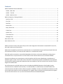
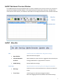
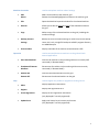
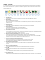
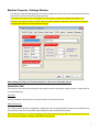
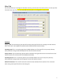
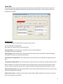
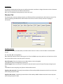
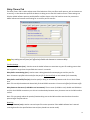
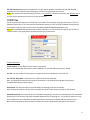
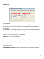
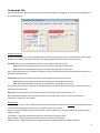
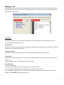
AxDNC Quick User / Configuration Guide 1 Contents AxDNC Dashboard Overview Window............................................................................................................................ 3 AxDNC – Menu Bar ..................................................................................................................................................... 3 AxDNC – Tool Bar........................................................................................................................................................ 5 AxDNC – Machine Grid ............................................................................................................................................... 6 Machine Properies / Settings Window ........................................................................................................................... 7 Serial Port Tab ............................................................................................................................................................ 7 Files Tab ...................................................................................................................................................................... 9 Send Tab ...................................................................................................................................................................10 Receive Tab ...............................................................................................................................................................11 Delay Timers Tab ......................................................................................................................................................12 TCP/IP Tab ................................................................................................................................................................13 Options Tab ..............................................................................................................................................................14 Commands Tab .........................................................................................................................................................15 Messages Tab ...........................................................................................................................................................17 How to Send a File ........................................................................................................................................................19 How to Receive a File....................................................................................................................................................20 AxDNC is used to transmit and receive CNC part files and configuration files between a networked file server PC, and a CNC machine on a factory floor. AxDNC has the capability to perform this communication via a standard Serial type interface (usually RS-232) and via an Ethernet interface, to a variety of CNC machines in a simultaneous manner. Each CNC machine connection is controlled independent of all others, and can be individually configured and controlled. There is no practical limit as to the number of CNC machine which can be connected to AxDNC. Presently the software can communicate to a Serial interface with flow control based upon a combination of hardware signals, and/or control codes such as Xon/Xoff. Communication speeds to 230,400 baud are supported. Communication speeds are generally dependent upon the capability of the CNC machine serial interface, and the length of the RS232 cable. Via an Ethernet port at the CNC machine, such as the Memex Ax2200HS Ethernet-to-Serial bridge, hosting communications to a Mx1053 serial interface, or an Mx1100 BTR, or a Ax9150 UMI, the AxDNC software can communicate with the CNC machine at Ethernet speeds to 100Mbps. Virtually unlimited distance between the file server and the CNC machine can be accomplished. This, together with running the local serial speed at its highest rate that the CNC machine can run, ensures the fastest and securest download speeds. 2 AxDNC Dashboard Overview Window The AxDNC Dashboard Overview Window loads on startup of AxDNC and is used as the main user interface to operate and configure the DNC software. This window consists of a Menu Bar at the top, a Tool Bar of the most common action buttons, and a Machine Grid used for the display and selection of the available machines. AxDNC - Menu Bar Edit Used for access to the DNC editor and general settings Open EditPlot Opens the Edit Plot program View/Edit Machine Protocols Opens windows to view or edit the ‘suggested’ communication/file settings predefined for a type/model of a machine. AxDNC Setting General Application settings Event Logs Open directories to various log files: (for diagnostic purposes) Data Logs Contains all send / receive operations for a machine by date/time stamp Trace / Error Used to log errors and internal program locations. Note: trace logging need to be enabled in the machine settings 3 Machine Connection Used to manipulate machine related settings Add Delete Adds a new machine to the machine grid Deletes the selected/highlighted machine on the machine grid Edit Opens the Machine Properties window for the selected machine Rename Allows you to edit the name and type of the selected machine on the grid. Copy Makes a copy of the selected machine on the grid (including the machine settings) Backup / Restore Settings Backup the current machine settings or restores a previous backup. Note: this is only a single file backup to AxDNC’s program directory as: AxDNCSetup.txt Show machine Displays a window of the machine communication traffic Operation Used to connect/disconnect machines on the grid and lunch external applications Auto Start Machines Connects all machines in the machine grid that are currently NOT connected (in ‘Remote Mode’). Shutdown All Remote Machines Disconnects all machines in the machine grid that are currently connected (in ‘Remote Mode’) Remote ON Remote OFF Connects the selected machine on the grid Disconnects the selected machine on the grid Help Used to register the product or upgrade an existing license Abort Displays application information Register Displays the registration form Check Registration Display current registration information (only displayed if currently registered) Update Ports Apply new license key to increase port licenses (only displayed if currently registered) 4 AxDNC – Tool Bar The Tool Bar allows for quick access to specific actions that are allowed for the selected machine in the Machine Grid or for the application. Note: Any action not available or applicable to the selected machine will be disabled (shown as a grey color) 1. Exit Application Disconnects all of the machine connections and Shuts down the AxDNC application software. 2. Open EditPlot Opens the AxDNC EditPlot file editor. Note: the ‘browse for file’ window will start in the send directory path of the machine currently selected in the Machine Grid. 3. Add New Machine Used to add new machine dialog box for creating a new machine in the machine grid. 4. Deletes a Machine Used to mark the selected machine in the grid for Deletion. Note: requires restarting the application to remove the machine. 5. Opens Machine Properties Used to configure the selected machine’s settings (communications, file directories, sending/receiving data formatting/translations/stripping / timeouts, and more). 6. Open the Connection (Remote Mode) (via a serial port or a TCP Port) Used to open a connection for the selected machine, using its current machine settings. This is required before transferring any data between the PC and the CNC machine control or the AxDNC software to respond to remote requests from the CNC machine control. 7. Close the Connection (Disconnect Remote Mode) Used to close the connection of the selected machine to the CNC machine control. This is required before making any changes to the selected machine’s settings. 8. Stop/Abort the Current Operation Used to stop the selected machine’s current data transfers or the application’s auto-start or auto-off routines. 9. Opens the Send/Receive Window Used to manually send a file or receive a file using the selected machine’s connection. 10. Auto ON Used to Connect ALL machines that are currently disconnected in the Machine Grid. 11. Auto OFF Used to Disconnect ALL machine that are currently connected in the Machine Grid. 12. View Machine Traffic Displays the data currently being transferred using the selected machine’s connection. (in a new window) 5 AxDNC – Machine Grid The Machine Grid displays the list of available machine connections to various CNC machine controls. This grid is used to select a machine for editing, perform some operations, and display the current status of the connection and/or operation. 1. CNC Machine Name Displays the machine name that identifies this connection The colored circle represents the following: Red: Disconnected Yellow: Idle / Waiting Yellow with Slash: Error occurred Green: Sending or Receiving part file data 2. State Displays the current state of this connection: Off Line: This machine if offline Remote Mode: This machine is connected Error: An error occurred trying to connect 3. Operation Displays information about the current operation or Error condition. Idle: the connection is open and waiting None: Connection is off line Sending <file name>: Sending the specified part file Receiving <file name>: Receiving the specified part file 4. Port Settings Displays information regarding the current Serial or TCP settings for this connection. 5. File Send Progress Dynamically displays the progress of the current part file being sent to a machine. 6. File Receive Progress Dynamically displays the about of bytes currently received from the machine. 7. Machine Type Displays the “type” of machine connected, as defined during the configuration set up. 6 Machine Properies / Settings Window The Machine Properies/Settings Window is used to configure a machine connection to the parameters of the CNC machine control and communication protocols. This process will require some knowledge of the CNC machine control that is being connected to, and therefore, may require access to the CNC machine control’s operators manual for information on finding or configuring the control’s current parameter settings. After making any changes to the machine properties, make sure to click Apply and OK Serial Port Tab The Serial Port Tab contains the settings for CNC machine control connections using a serial port. (either physical or virtual COM ports) Serial Port Select the COM Port with which this connection will access and communicate. Machine Protocols: This list box contains presets of “suggested” configurations for the specified CNC machine controls within this list. They will fill the Serial Port tab and the Send and Receive tabs with predefined settings. Note: these presets are only common settings for these CNC machine controls and are not guaranteed to work if they have been changed or configured with different parameters. 7 Connection Parameters Settings for the COM ports communication settings. These must match the CNC machine control’s serial settings. Baud Rate (Suggested): 4800 Data b its: (Suggested): 7 Parity (Suggested): Even Stop Bits (Suggested):2 Serial Data Flow Control This setting is to enable flow control to prevent overflow errors at the CNC machine control. None: No control over the data transfer. This setting could cause alarms or data corruption at the machine if the CNC machine control cannot keep up with the speed that the PC is sending data. Software: uses XON/XOFF data characters to stop/start the flow of data. Software flow control is the most common flow control used in CNC machine controls (all Fanuc controls should always use this) However, some older CNC machine controls may not be able to react fast enough to transmit these characters before their buffers overflow. Hardware: Uses CTS and RTS hardware signals in the serial cable to control the flow of data. Hardware flow control is not ways used by the CNC machine controls and the serial cable must have these hardware signals passed through to both cable ends. There are many cable configurations which have these wires jumped or disabled internally. Both: Attempts to use both Software and Hardware flow control to attempt to better react to stop requests in time. (can be used as a starting point or ‘don’t know’ option) Software Control Buffer Size: Specified the size of the buffer to send. (Requires Send type = Buffer) Send Type: Line: Send data one line at a time (Default) Buffer: Send data in a fixed size at a time XON/XOFF: Specifies the character codes to use for software flow control. Most common = DC1 / DC3 Only in odd cases does the control uses only DC2/DC4 Wait for XON: This will cause the DNC software to wait for the CNC machine to send a XON character before the DNC software will begin sending the part file. Checked = ON, Unchecked = OFF. Most CNC machine controls will issue a DC1 or DC2 character when it attempts to ‘Input’ a part file. Use this setting to pause the DNC software while you do a Read or Input at the CNC machine control. 8 Files Tab The Files tab allows you to configure the Windows directory paths that this CNC machine will use to select part files from and to store part files. It is recommended that these paths are configured for each machine. Directories Primary Send: The main directory path that will be used to select part files from for sending to the CNC machine. (This is also used in the Send/Receive window and the EditPlot default browse window) Secondary Send: This is a secondary path when the DNC software can’t find a part file in the primary directory. (Only used when issuing remote Send Requests from the CNC machine control) Primary Receive: The main directory path that will be used when storing part files that are received from the CNC machine control. (This is also used in the Send/Receive window) Secondary Receive: This is a secondary path for when the DNC software can’t access the primary directory. (Only used when issuing remote receive requests from the CNC machine control) Default File Extension: This is the file extension to with all browse windows for this machine. This is also used when storing receive part files with no extension given. 9 Send Tab The Send tab is used to configure how the part file data will be transmitted to the CNC machine control. This requires specifying the EOB (End Of Block) that the CNC machine control uses, as well as and any character stripping or translations. Set EOB on Send: It is required to specify the EOB used by the CNC machine control. LF = Line Feed, CR = Carriage Return Note: Most CNC machine controls will accept CR\ LF Start of Program: Enter the character in the part file to start transmitting from. Leave blank to start at the beginning End of Program: Enter the character in the part file that will mark the end of the part file (stop transmitting). Leave blank to transmit until the end of the part file. Transmit before sending the file: Use the ASCII Chart to specify characters to send before sending the part file data. Transmit after Sending the file: Use the ASCII Chart to specify characters to send after sending the part file data. Notes: Sometimes it is required to send NULLs (Hex 0) characters before or after the part file data get the CNC machine control to accept the part file. This is a timing condition associated with older CNC machine controls. Skip lines that start with: Character(s) entered here will be used by AxDNC to determine which lines to skip over while transmitting the part file data Skip lines that contain: Character(s) entered here will be used by AxDNC to determine which lines to skip over while transmitting the part file data. 10 Translations: This opens a window which allows you to configure character translations: change characters to other characters before being transmitted to the CNC machine control. Note: this is an advanced setting and only used in rare cases Receive Tab The Receive tab is used to configure how the part file data will be transmitted by the CNC machine control. This requires specifying the EOB that the CNC machine control uses as well as and any character stripping or translations. Set EOB on Receive: It is required to specify the EOB used by the CNC machine control in order to store the data in standard ASCII format . LF = Line Feed, CR = Carriage Return Note: Most CNC machine controls will output LF or CR as the EOB but you may need to use trial and error to find the correct EOB in order to store the part file correctly Start of Program: Enter the character use to detect when to start storing data. Leave blank to start at the beginning of a part file. End of Program: Enter the character in the part file that will mark the end of the part file (stop storing the part file). Leave blank to store everything sent from the CNC machine control. Skip lines that start with: Character(s) entered here will be used by AxDNC to determine which lines to skip over while storing the part file data Skip lines that contain: Character(s) entered here will be used by AxDNC to determine which lines to skip over while storing the part file data. 11 Delay Timers Tab The Delay Timers Tab is used to adjust some of the behaviors of the part file transfer process, such as timeouts on no activity, or slow down the speed of the data as its being sent to the CNC machine control. These settings can help the AxDNC software prevent possible buffer overflow alarms at the CNC machine control or prevent the AxDNC software to become stuck waiting for an end of a part file transfer. Note: Any setting set to 0 (zero) will effectively disable the timeout or cause no delay. Transfer Settings Transmission timeout (secs) : Used to cause the AxDNC software to terminate any part file sending process that has stopped for longer than the specified time interval- in seconds. Delay before transmitting (secs): Used to cause a delay/pause before attempting to send the part file. Note: Characters specified to be sent before the part file (in the Send Tab) are sent ahead of this time delay. Delay before each buffer/line (ms): Used to specify a delay (in milliseconds) between each line or block of data sent. Note: This can help slow down the data a little for Serial RS232 connection. It has no real effect for Ethernet traffic. Delay between characters (in 100 Micro sec increments): The on screen (0-30 Micro secs) should read 100 Micro secs) For Serial RS232 connections, use this to introduce delays between every character sent to the CNC machine control. Note: This can greatly reduce the speed of the data being sent to the CNC machine control and can be used to prevent buffer overflow alarms. Receiving File begin timeout (secs): Used to auto-end a part file receive operation if the AxDNC software hasn’t started receiving data after the specified time interval (once placed into receive mode). 12 File End timeout (secs): Used to close/end the part file receive operation (considers the part file received complete) if there’s no data received during the transfer for the specified time interval. Note: This timeout will need to be specified if there is no “End of File” character specified in the “Receive Tab” or else the receive operation will never end or save the part file. TCP/IP Tab For Ethernet communications, the TCP/IP Tab is only used if this connection is going to be used by a TCP Port instead of a Serial Port. This is only used to communicate directly to a TCP-to-Serial hardware devices that are connected to a CNC machine control (such as the Memex Mx1053/Mx1100/Ax9150 devices). Note: Many embedded Ethernet based CNC machine controls use an FTP protocol and require an FTP client to connect to them. They generally do not work with this type of connection. TCP/IP Information TCP/IP Address: The IP address for the device to connect to. Note: It is recommended that this be a static IP Address or a reserved Address that won’t change. Use TCP: This is to enable a TCP connection instead of a Serial Port specified in the Serial Tab Use TCP Poll /Keep Alive: Used to test for a valid TCP connection while idle. Note: This keeps the connection alive while the connection is not sending/receiving data (in idle) and is recommended if doing remote requests. Poll Interval: The amount of idle time to wait before attempting to test the connection. Note: setting this value too low (less than 2 seconds) can cause a large amount of traffic on the network. Reconnect Interval: The amount of time to wait before attempting to reconnect to a dropped/lost TCP connection. Powering off a TCP device will prevent the AxDNC Software from connecting to it. This reconnect feature is a way for the software to test if the device is powered back on or active on the network and auto-reconnect to it. Note: setting this value too low (less than 2 seconds) can cause a large amount of traffic on the network. 13 Options Tab The Options Tab handles some miscellaneous application setting related to the selected CNC machine control and part file optimization settings. Trace Logging Debug These settings are only use to help trace software errors and are only used for helping the developers solve software issues in the client environment and should be ignored (disabled) for normal machine configurations. File Optimization: These settings are for quick part file data conditioning for all part file transfers to/from the CNC machine control. These are only used to help speed up part file transfer by stripping out unneeded data within the part files as they are being transmitted. Note: When these settings are checked off, that the part file viewed on the CNC machine control display screen will likely appear different than the part file stored on the DNC file server. Remove spaces: Strip out all spaces in the program. Remove block numbers: Strip out all block numbers in the program. Remove comment lines: Strip out all lines starting with comments, lines starting with “(“ character. Remove blank lines: Strip out all lines that contain no data with in the program. Note: these “Remove” functions only affect the data being sent to the CNC machine control and won’t modify the part files stored on the PC. Remote Mode Machine at Startup: Checking this box will automatically attempt to connect this CNC machine control connection on startup of AxDNC. 14 Commands Tab The Commands Tab is where all of the Remote Command settings are configured, as well as auto-naming scheme of received part files. Remote Commands: Remote Commands are part files created/stored at the CNC machine control. This is a powerful tool used to allow operators to remotely request part files from the AxDNC software while at the CNC machine control. File Send: Define the command text that will be used to request part files to send. Start: Define the starting character(s) that will prefix the requested part file name End: Define the ending character(s) that will suffix the requested part file name Note: If the End character is not found (or left blank), the part file name used will be all of the characters up to the EOB (end of the block/line). File Receive: Define the command that will be used to request part files to be received. Start: Define the starting character(s) that will prefix the requested part file name End: Define the ending character(s) that will postfix the requested part file name Note: If the End character is not found (or left blank), the part file name used will be all of the characters up to the EOB (end of the block/line). Reset: Define a command that will reset the current state that the machine connection is in. Note: Nothing will happen if the machine connection is currently in Idle, so this is a way to make sure the connection is ready for a new request. Auto-Naming Auto-Naming is a way for the machine connection to receive a part file while in an idle state and properly store and rename the incoming part file using a line or characters within the part file. Note: This is only used when the connection is NOT in ‘Receive Mode’ prior to punching the part file from the CNC machine control. Left Textbox = Starting character(s) used for mark the start of the part file name. Right Textbox =Ending character(s) used to mark the end of the part file name. Middle Textbox = Additional characters to prepend to the text determined by the above textboxes. 15 Auto-Naming (Continued) Note: The machine connection will only look until the first occurrence of the starting character(s) found within the incoming part file data. Therefore, it is important to specify the starting character(s) that will be point to the correct location within the incoming part file that will contain the part file name to use. Auto-naming Examples: A suggestion is to use the “O” number within the part file as the starting mark or a comment after the O#### line that is the first comment in the part file. Beginning of part file: % O4567 (MYFILENAME) ….. Set the Auto-Naming fields to: Left Textbox = ( Right Textbox = ) This will rename the part file to: MYFILENAME Or Left Textbox = O Right Textbox = ( This will rename the part file to: 4567 Or Left Textbox = O Right Textbox = ( Middle TextBox = O This will rename the part file to: O4567 Note: The part file extension used on this part file will be the default extension specified in the Files Tab or if there was one included with the part filename specified within the name parsed from the part file. 16 Messages Tab The Messages Tab is used to ONLY when using remote commands to request part files from the AxDNC software. These are part files to be sent down to the CNC machine control to send messages to the Operator with errors or problems with their requests. Message Title The Message Title(s) are the list of responses available to choose from and the CNC checkboxes are used to select/activate which response to send. File NOT Found: Occurs when the part file name specified in the Remote Send Request was not found in the machine connection’s Send File Paths (specified in the Files Tab) Unknown Command: Occurs when there are no Send , Receive or auto-naming commands found within the part file. Unknown File: Occurs when the part filename parsed out of the request part file is blank or include invalid part file characters (*,#,$,/,\,:,;, ^) Any that cannot be used in a standard Windows part filename Path NOT Found: Occurs in the following: 1: The Send and/or Receive paths no longer exists or cannot be accessed. 2: The absolute path specified with in the part filename is invalid or doesn’t exist. Note: A specified complete path can be used if the CNC machine control allows those characters to be entered Example: O3456 (SEND-C:\DNCFile2\Program123 ) 17 Message Setting The text box contains the part file or text (for the selected Message Title) that will be sent to the operator in response to a problem with their remote request. The follows variable commands can be used within this text box to insert some additional information back to the Operator. $NAME = The name of the part file that was parsed/determined by the DNC software from the request part file sent. $PATH1 = The Primary Send path configured for this machine connection $PATH2 = The Secondary Send path configured for the machine connection Examples Message Settings : File Not Found: % O7000 (FILE $NAME NOT FOUND) (DIR1 $PATH1) (DIR2 $PATH2) M30 % Unknown Command: % O7000 (UNKNOWN COMMAND) M30 % Unknown File: % O7000 (UNKNOWN FILE RECEIVED) M30 % Unknown File Path: % O7000 (PATH NOT FOUND) (DIR1 $PATH1) (DIR2 $PATH2) M30 % 18 How to Send a File The following procedure explains how to send a part file to a CNC machine control connection ‘manually’ by using the AxDNC Send/Receive window. 1. Select / Click the desired Machine Connection on the Machine Grid where you want to send a part file. 2. Click the Connect button on the Toolbar to make a connection to the machine (skip if the machine is already connected) 3. Click the Send/Receive Button on the Tool Bar 4. Click the file Browse button in the Send/Receive window and find/open the part file to transfer to the machine. 5. Click the Send button to start the part file transfer. 19 The Send/Receive windows will close and the machine connection will now be in “Send Mode”. 6. Now go to the CNC machine control and put the machine to ‘Read’ or ‘Input’ mode to begin reading the part file from the serial port. Note: this method requires Wait for XON enabled in the Machine Properties to prevent the DNC software from sending data before the CNC machine control is ready to receive the part file by being in Read Mode. How to Receive a File The following procedure explains how to receive a part file from a CNC machine control connection ‘manually’ by using the AxDNC Send/Receive window. 1. Select / Click the desired Machine Connection on the Machine Grid that you want to send a part file to. 2. Click on the Connect button on the Toolbar to make a connection to the CNC machine control (skip if the CNC machine control is already connected) 3. Click the Send/Receive Button on the Tool Bar 20 4. Click the Receive button with in the Send/Receive window. 5. Specify the part file name and select the location to store the part file. The Send/Receive window will now close and that CNC machine control connection will be in ‘Receive Mode’. 6. Now go to the CNC machine control, select the part file to send and select “Punch” or “Output” to begin sending the part file out of the CNC machine control to the PC. //end of manual 21