1
SUPERSTAR II
Firmware
Reference Manual
OM-20000086
Rev 5
Proprietary Notice
SUPERSTAR II Firmware Reference Manual
Publication Number:
OM-20000086
Revision Level:
5
Revision Date:
2005/06/09
Proprietary Notice
The software described in this document is furnished under a licence agreement or non-disclosure agreement.
The software may be used or copied only in accordance with the terms of the agreement. It is against the law to
copy the software on any medium except as specifically allowed in the license or non-disclosure agreement.
No part of this manual may be reproduced or transmitted in any form or by any means, electronic or
mechanical, including photocopying and recording, for any purpose without the express written permission of a
duly authorized representative of NovAtel Inc.
The information contained within this manual is believed to be true and correct at the time of publication.
NovAtel® is a registered trademark of NovAtel Inc.
All other brand names are trademarks of their respective holders.
© Copyright 2003-2005 NovAtel Inc. All rights reserved.
Unpublished rights reserved under International copyright laws.
2
SUPERSTAR II Firmware Reference Manual Rev 5
Table of Contents
Software License
Customer Service
Foreword
1 Messages
8
10
11
13
1.1 Physical Link Layer........................................................................................................................ 13
1.2 Data Link Layer.............................................................................................................................. 13
1.2.1 Bit Ordering .......................................................................................................................... 13
1.2.2 Message Block Structure ..................................................................................................... 13
1.2.3 Message Block Types .......................................................................................................... 15
1.3 Initiation ......................................................................................................................................... 17
1.4 Data Link........................................................................................................................................ 18
1.5 Error Recovery and Timing............................................................................................................ 18
1.5.1 Block ID Complement Error ................................................................................................. 18
1.5.2 Checksum Error ................................................................................................................... 18
1.5.3 Time-Out Errors ................................................................................................................... 18
1.5.4 Frame Synchronization Errors ............................................................................................. 18
1.6 Checksum Calculation Rules......................................................................................................... 19
1.7 Field Types .................................................................................................................................... 19
2 Input Commands
21
2.1 Command Format.......................................................................................................................... 21
2.2 Command Settings ........................................................................................................................ 21
2.3 Commands by Function................................................................................................................. 21
2.4 Factory Defaults............................................................................................................................. 25
2.5 Binary Protocol Command Reference ........................................................................................... 25
2.5.1 Reset Receiver ID# 2 .......................................................................................................... 25
2.5.2 Request Current Channel Assignment Data ID# 6 ............................................................. 25
2.5.3 Request Navigation Data (User Coordinates) ID# 20 ......................................................... 26
2.5.4 Request Navigation Data (ECEF Coordinates) ID# 21 ....................................................... 26
2.5.5 Request Ephemeris Data (ICD-GPS-200 Format) ID# 22 .................................................. 27
2.5.6 Request Measurement Block Data ID# 23 .......................................................................... 27
2.5.7 Set Receiver Configuration ID# 30 ...................................................................................... 28
2.5.8 Request Receiver Configuration ID# 30 .............................................................................. 29
2.5.9 Request Satellite Visibility, Data and Status ID# 33 ............................................................ 30
2.5.10 Request DGPS Configuration ID# 43 ................................................................................ 30
2.5.11 Request Hardware/Software Identification ID# 45 ............................................................ 31
2.5.12 Request Base Station Status ID# 47 ................................................................................. 31
2.5.13 Request Differential Message Status ID# 48 .................................................................... 32
2.5.14 Request Receiver Status ID# 49 ....................................................................................... 32
2.5.15 Request Satellite Health Summary ID# 50 ........................................................................ 32
2.5.16 Initiate Self-Test ID# 51 ..................................................................................................... 33
2.5.17 Initiate Link ID# 63 ............................................................................................................ 33
2.5.18 Set Channel Deselection ID# 64 ....................................................................................... 34
2.5.19 Request RTCM Data Message Received ID# 65 .............................................................. 34
2.5.20 Request SBAS Data ID# 67 .............................................................................................. 35
2.5.21 Request SBAS Status Message ID# 68 ............................................................................ 35
2.5.22 Set Timing Parameters ID# 69 .......................................................................................... 36
2.5.23 Request Ionospheric and UTC Time Data ID# 75 ............................................................. 38
2.5.24 Request Almanac Data ID# 76 .......................................................................................... 38
SUPERSTAR II Firmware Reference Manual Rev 5
3
Table of Contents
2.5.25 Update Almanac ID# 77 .................................................................................................... 39
2.5.26 Almanac Data Upload ID# 78 ............................................................................................ 39
2.5.27 Specific Almanac Data Upload ID# 79 .............................................................................. 40
2.5.28 Set Operating Mode ID# 80 ............................................................................................... 42
2.5.29 Set Mask Angle ID# 81 ...................................................................................................... 43
2.5.30 Set DGPS Configuration ID# 83 ........................................................................................ 44
2.5.31 Set Tropospheric/Ionospheric Model Use ID# 84 .............................................................. 45
2.5.32 Set Mean Sea Level Model Use ID# 86 ............................................................................ 46
2.5.33 Set Fixed Height Mode ID# 87 .......................................................................................... 46
2.5.34 Select/Define Datum to Use ID# 88 .................................................................................. 46
2.5.35 Satellite Deselection ID# 90 .............................................................................................. 52
2.5.36 Set Differential Message Configuration ID# 91 ................................................................. 53
2.5.37 Request to Track a Particular Satellite ID# 95 .................................................................. 54
2.5.38 Erase NVM ID# 99 ............................................................................................................ 55
2.5.39 Set Date and Time ID# 103 ............................................................................................... 56
2.5.40 Set Default Binary Message List ID# 105 .......................................................................... 57
2.5.41 Configure COM1 Port Mode ID# 110 ................................................................................ 58
2.5.42 Request Timing Information ID# 113 ................................................................................. 58
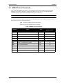
2.6 NMEA Protocol Commands........................................................................................................... 59
2.6.1 $PMCAG, 000 Configure COM1 Port Command ................................................................ 60
2.6.2 $PMCAG, 001 Initialize Time and Position ......................................................................... 61
2.6.3 $PMCAG, 003 Initiate Self-Test .......................................................................................... 62
2.6.4 $PMCAG, 004 Request Log Command .............................................................................. 63
2.6.5 $PMCAG, 005 Set Output Configuration Command ........................................................... 64
2.6.6 $PMCAG, 007 Erase Non-Volatile Memory Command ....................................................... 65
2.6.7 $PMCAG, 008 Set Receiver Parameter Command ............................................................ 66
2.6.8 $PMCAG, 009 Define Waypoint in MGRS Format .............................................................. 68
2.6.9 $PMCAG, 010 Select Active Waypoint ............................................................................... 70
2.6.10 $PCMAG, 012 Receiver Configuration .............................................................................. 71
3 Output Logs
73
3.1 Logs ............................................................................................................................................... 73
3.1.1 Message Latencies ............................................................................................................. 73
3.2 Logs by Function ........................................................................................................................... 73
3.3 Binary Protocol Logs...................................................................................................................... 77
3.3.1 Current Channel Assignment Data (1-6) ID# 6 ................................................................... 77
3.3.2 Current Channel Assignment Data (7-12) ID#7 .................................................................. 79
3.3.3 Navigation Data (User Coordinates) ID# 20 ........................................................................ 81
3.3.4 Navigation Data (ECEF Coordinates) ID# 21 ...................................................................... 83
3.3.5 Ephemeris Data ID# 22 ....................................................................................................... 86
3.3.6 Measurement Block Data ID# 23 ........................................................................................ 87
3.3.7 Receiver Configuration ID# 30 ............................................................................................ 89
3.3.8 Satellite Visibility Data and Status ID# 33 ........................................................................... 90
3.3.9 DGPS Configuration ID# 43 ................................................................................................ 92
3.3.10 Hardware/Software Identification ID# 45 ........................................................................... 93
3.3.11 Base Station Status Data ID# 47 ....................................................................................... 94
3.3.12 Differential Message Status ID# 48 ................................................................................... 95
3.3.13 Receiver Status ID# 49 ..................................................................................................... 97
3.3.14 Satellite Health Summary ID# 50 ...................................................................................... 99
3.3.15 Self-Test Results ID# 51 ................................................................................................. 101
3.3.16 RTCM Data Message Received ID# 65 .......................................................................... 104
3.3.17 SBAS Data ID# 67 ........................................................................................................... 105
3.3.18 SBAS Status Message ID# 68 ........................................................................................ 106
3.3.19 Ionospheric and UTC Time Data ID# 75 ......................................................................... 107
4
SUPERSTAR II Firmware Reference Manual Rev 5
Table of Contents
3.3.20 Almanac Data ID# 76 ...................................................................................................... 108
3.3.21 Almanac Reception Status ID# 78 .................................................................................. 110
3.3.22 Timing Status ID# 113 ..................................................................................................... 111
3.3.23 Link Overload Error Message ID# 125 ............................................................................ 113
3.3.24 Acknowledge Log ID# 126 .............................................................................................. 114
3.4 NMEA Protocol Logs ................................................................................................................... 115
3.4.1 $PMCAG, 900 Navigation Status ...................................................................................... 116
3.4.2 $PMCAG, 902 Self-Test Results ....................................................................................... 117
3.4.3 $PMCAG, 906 Bearing, Distance and Delta-Elevation to Waypoint ................................. 118
3.4.4 $PMCAG, 907 User Position in MGRS Format ................................................................. 119
3.4.5 $PMCAG, 908 Receiver Parameter Status ....................................................................... 120
3.4.6 $PMCAG, 912 Receiver Configuration ............................................................................. 121
3.4.7 $GPGGA Global Positioning System Fix Data .................................................................. 122
3.4.8 $GPGLL Geographic Position Latitude/Longitude ............................................................ 123
3.4.9 $GPGSA GPS DOP and Active Satellites ......................................................................... 124
3.4.10 $GPGSV GPS Satellites In View .................................................................................... 125
3.4.11 $GPRMC Recommended Minimum Specific GPS Data ................................................. 127
3.4.12 $GPVTG Track Made Good and Ground Speed ............................................................ 128
3.4.13 $GPZDA Time and Date ................................................................................................. 129
4 Firmware Updates
130
4.1 System Requirements ................................................................................................................. 130
4.2 Utility Installation.......................................................................................................................... 130
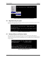
4.3 Registration Key .......................................................................................................................... 130
4.4 Registration Key Accepted .......................................................................................................... 131
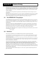
4.5 Starting Software and Options Update ........................................................................................ 131
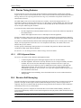
4.5.1 Programming Success ....................................................................................................... 132
Appendices
A
B
C
D
E
F
SUPERSTAR II Card Models
Precise Timing
Measurements
SBAS Positioning
Waypoint Navigation
Message Formats
SUPERSTAR II Firmware Reference Manual Rev 5
133
134
138
145
147
148
5
Figures
1
2
3
4
5
6
7
8
9
Example of Part of the MGRS Grid ............................................................................................... 69
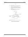
ECEF Coordinate System ............................................................................................................. 85
Update Registration Window in DOS .......................................................................................... 130
Paste the Registration Key into the DOS Window ...................................................................... 131
Configuration Accepted ............................................................................................................... 131
Update Utility Activation .............................................................................................................. 131
End of Programming Session...................................................................................................... 132
Modulated GPS Data (Doppler Present) ..................................................................................... 138
Demodulated GPS Data (Doppler Present) ................................................................................ 139
6
L1 GPS Firmware Reference Manual Rev 5
Tables
1
2
3
4
5
6
7
8
9
10
11
12
13
14
15
16
17
18
19
20
21
22
23
Related Publications .................................................................................................................... 12
Message Modes ........................................................................................................................... 16
Field Types ................................................................................................................................... 20
Commands By Function Table ..................................................................................................... 21
SUPERSTAR II Binary Commands Summary ............................................................................. 24
Preset Configurations ................................................................................................................... 29
DATUM Description ..................................................................................................................... 48
Ellipsoid Description Table ........................................................................................................... 51
Element to Erase .......................................................................................................................... 55
NMEA Input Commands .............................................................................................................. 59
Baud Rate Selection .................................................................................................................... 60
PMCAG, 007 Elements ................................................................................................................ 65
Message Vs. Latency ................................................................................................................... 73
Logs By Function Table ............................................................................................................... 73
SUPERSTAR II Log Summary ..................................................................................................... 76
Rover Message ID# 48 ................................................................................................................ 95
Base Message ID# 48 .................................................................................................................. 96
List of NMEA Logs ..................................................................................................................... 115
SUPERSTAR II Software Models .............................................................................................. 133
Time Estimator Status Conditions .............................................................................................. 136
Residual Solution Status Conditions .......................................................................................... 136
Clock Drift (CD) Effects .............................................................................................................. 139
Measurement Bits ...................................................................................................................... 141
L1 GPS Firmware Reference Manual Rev 5
7
Software License
Software License
BY INSTALLING, COPYING, OR OTHERWISE USING THE SOFTWARE PRODUCT, YOU AGREE TO BE
BOUND BY THE TERMS OF THIS AGREEMENT. IF YOU DO NOT AGREE WITH THESE TERMS OF USE,
DO NOT INSTALL, COPY OR USE THIS ELECTRONIC PRODUCT (SOFTWARE, FIRMWARE, SCRIPT
FILES, OR OTHER ELECTRONIC PRODUCT WHETHER ON A CD OR AVAILABLE ON THE COMPANY
WEB SITE) (HEREINAFTER REFERRED TO AS "SOFTWARE").
1.
License: NovAtel Inc. ("NovAtel") grants you a non-exclusive, non-transferable license (not a sale) to, where
the Software will be used on NovAtel supplied hardware or in conjunction with other NovAtel supplied
software, use the Software with the product(s) as supplied by NovAtel. You agree not to use the Software for
any purpose other than the due exercise of the rights and licences hereby agreed to be granted to you.
2.
Copyright: NovAtel owns, or has the right to sublicense, all copyright, trade secret, patent and other
proprietary rights in the Software and the Software is protected by national copyright laws, international treaty
provisions and all other applicable national laws. You must treat the Software like any other copyrighted
material except that you may make one copy of the Software solely for backup or archival purposes (one copy
may be made for each piece of NovAtel hardware on which it is installed or where used in conjunction with
other NovAtel supplied software), the media of said copy shall bear labels showing all trademark and copyright
notices that appear on the original copy. You may not copy the product manual or written materials
accompanying the Software. No right is conveyed by this Agreement for the use, directly, indirectly, by
implication or otherwise by Licensee of the name of NovAtel, or of any trade names or nomenclature used by
NovAtel, or any other words or combinations of words proprietary to NovAtel, in connection with this
Agreement, without the prior written consent of NovAtel.
3.
Patent Infringement: NovAtel shall not be liable to indemnify the Licensee against any loss sustained by it as
the result of any claim made or action brought by any third party for infringement of any letters patent,
registered design or like instrument of privilege by reason of the use or application of the Software by the
Licensee or any other information supplied or to be supplied to the Licensee pursuant to the terms of this
Agreement. NovAtel shall not be bound to take legal proceedings against any third party in respect of any
infringement of letters patent, registered design or like instrument of privilege which may now or at any future
time be owned by it. However, should NovAtel elect to take such legal proceedings, at NovAtel's request,
Licensee shall co-operate reasonably with NovAtel in all legal actions concerning this license of the Software
under this Agreement taken against any third party by NovAtel to protect its rights in the Software. NovAtel
shall bear all reasonable costs and expenses incurred by Licensee in the course of co-operating with NovAtel in
such legal action.
Restrictions: You may not: (1) copy (other than as provided for in paragraph 2), distribute, transfer, rent, lease,
lend, sell or sublicense all or any portion of the Software; (2) modify or prepare derivative works of the
Software; (3) use the Software in connection with computer-based services business or publicly display visual
output of the Software; (4) transmit the Software over a network, by telephone or electronically using any
means; or (5) reverse engineer, decompile or disassemble the Software. You agree to keep confidential and use
your best efforts to prevent and protect the contents of the Software from unauthorized disclosure or use.
4.
8
Term and Termination: This Agreement and the rights and licences hereby granted shall continue in force in
perpetuity unless terminated by NovAtel or Licensee in accordance herewith. In the event that the Licensee
shall at any time during the term of this Agreement: i) be in breach of its obligations hereunder where such
breach is irremediable or if capable of remedy is not remedied within 30 days of notice from NovAtel requiring
its remedy; or ii) be or become bankrupt or insolvent or make any composition with its creditors or have a
receiver or manager appointed of the whole or any part of its undertaking or assets or (otherwise as a solvent
company for the purpose of and followed by an amalgamation or reconstruction hereunder its successor shall
be bound by its obligations hereunder) commence to be wound up; or iii) be acquired or otherwise come under
the direct or indirect control of a person or persons other than those controlling it, then and in any event
NovAtel may forthwith by notice in writing terminate this Agreement together with the rights and licences
hereby granted by NovAtel. Licensee may terminate this Agreement by providing 30 days prior written notice
to NovAtel. Upon termination, for any reasons, the Licensee shall promptly, on NovAtel's request, return to
NovAtel or at the election of NovAtel destroy all copies of any documents and extracts comprising or containing
the Software. The Licensee shall also erase any copies of the Software residing on Licensee's computer
equipment. Termination shall be without prejudice to the accrued rights of either party, including payments
due to NovAtel. This provision shall survive termination of this Agreement howsoever arising.
L1 GPS Firmware Reference Manual Rev 5
Software License
5.
Warranty:
a. For 90 days from the date of shipment of new purchased product, NovAtel warrants that the media (for example, compact
disk) on which the Software is contained will be free from defects in materials and workmanship. This warranty does not
cover damage caused by improper use or neglect.
b. NovAtel does not warrant the contents of the Software or that it will be error free. The Software is furnished "AS IS" and
without warranty as to the performance or results you may obtain by using the Software. The entire risk as to the results
and performance of the Software is assumed by you.
6.
Indemnification: NovAtel shall be under no obligation or liability of any kind (in contract, tort or otherwise and
whether directly or indirectly or by way of indemnity contribution or otherwise howsoever) to the Licensee and
the Licensee will indemnify and hold NovAtel harmless against all or any loss, damage, actions, costs, claims,
demands and other liabilities or any kind whatsoever (direct, consequential, special or otherwise) arising
directly or indirectly out of or by reason of the use by the Licensee of the Software whether the same shall arise
in consequence of any such infringement, deficiency, inaccuracy, error or other defect therein and whether or
not involving negligence on the part of any person.
7.
For Software UPDATES and UPGRADES, and regular customer support, contact the NovAtel GPS Hotline at
1-800-NOVATEL (U.S. or Canada only), or 403-295-4900, Fax 403-295-4901, e-mail to [email protected],
website: http://www.novatel.ca or write to:
NovAtel Inc.
Customer Service Dept.
1120 - 68 Avenue NE,
Calgary, Alberta, Canada T2E 8S5
8.
Disclaimer of Warranty and Limitation of Liability:
a. THE WARRANTIES IN THIS AGREEMENT REPLACE ALL OTHER WARRANTIES, EXPRESS OR IMPLIED,
INCLUDING ANY WARRANTIES OF MERCHANTABILITY OR FITNESS FOR A PARTICULAR PURPOSE.
NovAtel DISCLAIMS AND EXCLUDES ALL OTHER WARRANTIES. IN NO EVENT WILL NovAtel's LIABILITY
OF ANY KIND INCLUDE ANY SPECIAL, INCIDENTAL OR CONSEQUENTIAL DAMAGES, INCLUDING LOST
PROFITS, EVEN IF NovAtel HAS KNOWLEDGE OF THE POTENTIAL LOSS OR DAMAGE.
b. NovAtel will not be liable for any loss or damage caused by delay in furnishing the Software or any other performance
under this Agreement.
c. NovAtel's entire liability and your exclusive remedies for our liability of any kind (including liability for negligence) for
the Software covered by this Agreement and all other performance or non-performance by NovAtel under or related to this
Agreement are to the remedies specified by this Agreement.
This Agreement is governed by the laws of the Province of Alberta, Canada. Each of the parties hereto irrevocably
attorns to the jurisdiction of the courts of the Province of Alberta.
L1 GPS Firmware Reference Manual Rev 5
9
Customer Service
Customer Service
Contact Information
If you have any questions or concerns regarding your SUPERSTAR II-based receiver, please contact NovAtel
Customer Service using any one of the following methods:
NovAtel GPS Hotline:
1-800-NOVATEL (Canada and the U.S.)
403-295-4900 (International)
Fax:
403-295-4901
E-mail:
[email protected]
Website:
www.novatel.com
Write:
NovAtel Inc. Customer Service Dept.
1120 - 68 Avenue NE
Calgary, Alberta, Canada
T2E 8S5
Before contacting NovAtel Customer Service regarding software concerns, please do the following:
1. Issue the NVM Reset command, Message ID# 99 on Page 55, with value 0 to reset all NVM.
2. Log the following data requests to a file on your PC for 30 minutes
Receiver Status, Message ID# 49
Ephemeris Data, Message ID# 22
Measurement Block, Message ID# 23
HW/SW Identification, Message ID# 45
one shot
continuous
1 Hz
one shot
3. Send the file containing the log to NovAtel Customer Service, using either the NovAtel ftp site at ftp://
ftp.novatel.ca/incoming or the [email protected] e-mail address.
Firmware Updates
Firmware updates are firmware revisions to an existing model, which improve basic functionality of the GPS
receiver. See also Chapter 4, Firmware Updates on Page 130.
Firmware upgrades are firmware releases, which increase basic functionality of the receiver from one model to
a higher level model type. When available, upgrades may be purchased at a price, which is the difference
between the two model types on the current NovAtel GPS Price List plus a nominal service charge.
If you need further information, please contact a NovAtel authorized dealer or NovAtel directly using one of
the methods given above.
10
L1 GPS Firmware Reference Manual Rev 5
Foreword
Foreword
Congratulations on purchasing a NovAtel product.
Whether you have bought a stand alone SUPERSTAR II card or a packaged receiver, the SUPERSTAR II User
Manual, or SMART ANTENNA User Manual, will help you get the hardware operational. Afterwards, this text
is your primary firmware command and logging reference.
Scope
This manual describes each message that the NovAtel SUPERSTAR II receivers are capable of accepting or
generating.
A SMART ANTENNA contains a SUPERSTAR II card.
Sufficient detail is provided so that you should understand the purpose, syntax, and structure of each command
or log and be able to effectively communicate with the receiver, thus enabling you to effectively use and write
custom interfacing software for specific needs and applications. The manual is organized into chapters that
allow easy access to appropriate information about the receiver.
There is also optional Satellite Based Augmentation System (SBAS) signal functionality in SUPERSTAR IIbased products. Please see Appendix A, SUPERSTAR II Card Models on Page 133 and Appendix D, SBAS
Positioning on Page 145 of this manual and the Conventions section below for more information.
This manual does not address any of the receiver hardware attributes or installation information. Please consult
the appropriate hardware user manual for technical information on these topics, see Table 1 on Page 12.
Furthermore, should you encounter any functional, operational, or interfacing difficulties with the receiver,
consult the same hardware manual for NovAtel warranty information. Customer support information may be
found in this manual on Page 10.
What’s New in Firmware Version 1.300 Since Version 1.200?
Version 1.300 of the firmware adds the following to this manual:
1.
Support for 2-D mode, which is useful when there are only 3 satellites available for computing a solution
2.
A fixed height mode command, Message ID# 87 to enable 2-D mode in 1. above, see Page 46
3.
The NMEA Message Format and the NMEA Checksum Calculation, see Section F.2, NMEA Format Data
Messages on Page 150
4.
Non-SBAS models are now available, see Appendix A, SUPERSTAR II Card Models on Page 133
5.
5 Hz carrier phase (CP) models that are capable of 1, 2 or 5 Hz measurements, see Table 19 on Page 133.
The most up-to-date version of this manual can be downloaded from our website at http://www.novatel.com/
Downloads/docupdates.html.
If you are unfamiliar with any of the terms used in this manual, refer to the GPS+ Reference Manual available
on our website at the address above.
Prerequisites
As this reference manual is focused on SUPERSTAR II commands and logging protocol, it is necessary to
ensure that the receiver has been properly installed and powered up according to the instructions outlined in
your product’s companion hardware user manual before proceeding.
SUPERSTAR II Firmware Reference Manual Rev 5
11
Foreword
Conventions
This manual covers the full performance capabilities of NovAtel SUPERSTAR II-based receivers.
A list of models may be found in Appendix A, SUPERSTAR II Card Models on Page 133.
Simple conventions are:
H
b
The number preceding H is a hexadecimal number
The number preceding b is a binary number
In tables where values are missing they are reserved for future use.
Messages and status words are output as hexadecimal numbers and must be converted to binary format (and in
some cases then also to decimal). Conversions and their binary or decimal results are always read from right to
left.
Related Publications
The related publications are listed in Table 1 below.
Table 1: Related Publications
PUBLICATION NAME
[1] ICD-GPS-200 Rev. B
NAVSTAR GPS Space Segment/Navigation Interface
[2] RTCM-104 version 2.1
January 1994
Recommended Standards for Differential NAVSTAR GPS
Radio Technical Commission for Maritime Services
[3] SAE J1211
SAE Recommended Environmental Practices for Electronic
Equipment Design
[4] NMEA-0183 Rev 2.20
National Marine Electronics Association Standard for
Interfacing
[5] STARVIEW User Manual
NovAtel Part Number OM-20000081 a
[6] SMART ANTENNA User Manual
NovAtel Part Number OM-20000078 a
[7] SUPERSTAR II User Manual
NovAtel Part Number OM-20000077 a
a.
12
PUBLICATION NAME
Adobe PDF versions of these manuals can be downloaded from our website at http://
www.novatel.com/Downloads/docupdates.html.
SUPERSTAR II Firmware Reference Manual Rev 5
Chapter 1
Messages
This section defines a serial data transfer protocol for the receiver. The serial data is sent in variable size
message blocks, where the message block header defines the contents and size of all message blocks.
For discussion purposes, the PC is the controlling host computer, and the GPS receiver is a SUPERSTAR IIbased product. StarView provides a graphical interface to control and monitor the operation of your NovAtel
receiver. A StarView CD is supplied with development kits, otherwise StarView is available on our website at
http://www.novatel.com/Downloads/fwswupdates.html.
Prior to entering the protocol, use StarView to set up both the PC and GPS receiver at the same baud rate and
data setting. Upon entering the protocol, the PC and GPS receiver wait for message blocks. Refer also to the
StarView User Manual, see Table 1 on Page 12.
1.1
Physical Link Layer
The electrical signals used are those through the communication port. Only the receive and send lines are
required. The serial port is asynchronous and should be set up with 1 start bit, 8 data bits, no parity bit, and one
stop bit. Asynchronous data is generated at irregular intervals when the output has changed. A default baud rate
of either 9600 or 19200 bps is used depending on your model. Both the PC and receiver are operating at the
same rate and can be reset (see Message ID# 110 on Page 58). See also Appendix A, SUPERSTAR II Card
Models, starting on Page 133.
1.2
1.2.1
Data Link Layer
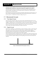
Bit Ordering
The ordering of data within message blocks is such that the least significant bit (LSB) is the first
bit received and the most significant bit (MSB) is the last bit in the sequence.
Order
MSB
LSB
7 6 5 4 3 2 1 0
This ordering is applied to all data formats, which include integer values, floating point values,
and character strings.
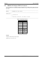
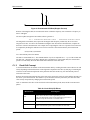
1.2.2
Message Block Structure
Message blocks are used for communication between the GPS receiver and your PC. Each
message block consists of a header and possibly data. The data portion of the block is of variable
length depending on the message. The header has a fixed length of 4 bytes, consisting of a start-ofheader character (SOH), block ID, block ID complement and message data length. Each block has
a truncated 16-bit word containing the checksum associated with the complete content of the
block. It is appended at the end of the data portion of the block.
The message block structure has the following form:
byte 1:
SOH
byte 2:
ID#
byte 3:
Complementary ID#
byte 4:
Message Data Length (0-255)
byte 5 .. n:
n-4 Data Bytes
byte n+1 .. n+2:
Checksum
SUPERSTAR II Firmware Reference Manual Rev 5
13
Chapter 1
Messages
where:
SOH
Start of header character (01H or decimal 1).
ID#
Byte containing the block ID numeric value. The block ID number field is used uniquely
to identify the format of the data portion of the block. Since only 7 bits are needed for the
ID#, the higher bit is used to identify if the message is sent in one shot (the message is
output only once) or continuous (the message is output continuously at its message rate
normally once per second) mode. This prevents an unnecessary increase in overhead by
eliminating any extra bytes in the protocol. There are exceptions to this use of the higher
bit as seen in example 2 below.
1. For example, Message ID# 50 with:
ID = 32H; binary 0011 0010 where the msb = 0 for one shot
01 32 CD 00 00 01
or
ID = B2H; binary 1011 0010 where the msb = 1 for continuous
01 B2 4D 00 00 01
2. Take the case of Message ID#23, where setting the higher bit is used to identify if the
message is to be logged in continuous mode or if the message is to be stopped.
For example, Message ID# 23 with:
ID# = 17H; binary 0001 0111 where the msb = 0 to stop output
01 17 E8 00 01 01
or
ID# = 97H; binary 1001 0111 where the msb = 1 for continuous output
01 97 68 01 00 01 01
For most messages, MSB = 0 is for one shot or to cancel continuous, MSB = 1 is for continuous unless
specified otherwise. See byte 2 above and Section 1.2.1, Bit Ordering.
Complimentary ID#
1's complement of the ID# field. This can be calculated as:
Complimentary ID# = 255 - (Block ID#) or Cmpl ID# = (Block ID#) XOR 255
This field, in conjunction with the SOH, helps to synchronize the message blocks, since
the SOH character can appear within the data, the Complimentary ID# field validates the
header contents and thus confirms the start of the block.
Message Data Length
One byte containing the length of the data part of the message in bytes (excluding header
and checksum).
Checksum
This fields contains the checksum value for the message blocks, which includes the
header and data. The checksum calculation is discussed in Checksum Calculation Rules
on Page 19.
14
SUPERSTAR II Firmware Reference Manual Rev 5
Messages
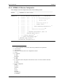
1.2.3
Chapter 1
Message Block Types
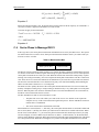
1.2.3.1
PC to GPS Receiver Message Types
There are 5 types of messages that can be sent from your PC to the GPS receiver:
Dummy Message (ID# 0):
Reserved
Initiate Link (ID# 63):
This is the first message sent by the PC upon entering the protocol. It informs the receiver
that communication is desired. A password is encoded in the message. This message
interrupts all receiver logs and waits for new data request messages.
Data Request (DR) Message:
Request the receiver to turn on/off broadcast data or to send data only once. The MSB of
the ID# indicates the type of request with "1" to turn on broadcast, and "0" for once only
or to turn off the broadcast.
Command Message (CM):
Request a particular receiver action other than a data request. The MSB of the ID# may
be used to set the receiver to Normal mode (MSB=0) or to Special mode (MSB=1).
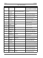
For DR messages, Normal mode is for one shot output and Special mode is for continuous output. See also
the ID# description on Page 14. However, for CMs, the Special mode has another meaning. Table 2 on
Page 16 shows examples of Message ID#s where using Normal mode or Special mode does not send the
message out in one shot or continuous mode.
Data Message (DM):
Any message containing data to be saved in receiver memory or processed by the
receiver.
SUPERSTAR II Firmware Reference Manual Rev 5
15
Chapter 1
Messages
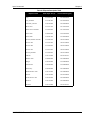
Table 2: Message Modes
Message ID#
16
Description
Normal Mode
Special Mode
2
Reset Receiver
Reset
N/A - The information does not change
so this is unnecessary. To continuously
reset the receiver is not recommended
23
Request
Measurement
Block Data
Off - Turns off continuous mode and
does not give a one shot output
On (default)
30
Set Receiver
Configuration
Set
N/A - Once set, the configuration does
not need to be reset continuously
45
HW/SW ID
Number
Identify
N/A - The information does not change
unless you update your software
64
Set Channel
Deselection
Set
N/A - Once set, channels do not need to
be deselected continuously
69
Set Timing
Parameters
Set
N/A - Once set, the timing parameters
do not need to be updated continuously
77
Update Almanac
Update
N/A - Almanac data does not have to be
renewed continuously
78
Common
Almanac
Upload
N/A - Almanac data does not need to be
reloaded continuously
79
Specific Almanac
80
Set Position/
Operating Mode
Set
N/A - Once set, the mode does not need
to be reset continuously
81
Set Mask Angle
Set
N/A - Once set, the mask angle does
not need to be reset continuously
83
Set DGPS
Configuration
Set
N/A - Once set, the DGPS mode does
not need to be reset continuously
84
Tropospheric/
Ionospheric Model
On (default)
Off - It is not recommended that you turn
off the use of this model - for advanced
users of GPS only
86
MSL Model
On
Off (default)
88
Datum to Use
Select/Define
N/A - Once set, the datum does not
need to be updated continuously
90
Set Satellite
Deselection
Set
N/A - Once set, a satellite does not need
to be deselected continuously
91
Set DGPS
Configuration
Set
N/A - Once set, the DGPS configuration
does not need to be reset continuously
95
Particular Satellite
Request to track
N/A - Does not need to be re-requested
99
Erase NVM
Erase
N/A - Does not need to be re-erased
103
Set Date and
Time
Set
N/A - Once set, the date and time do not
need to be updated continuously
105
Set Default Binary
Message List
Set
N/A - Once set, the message list does
not need to be reset continuously
110
Configure COM1
Configure
N/A - The COM1 port does not need to
be reconfigured continuously
SUPERSTAR II Firmware Reference Manual Rev 5
Messages
1.2.3.2
Chapter 1
GPS Receiver to PC Message Types
There are 6 types of messages that can be output from the GPS receiver to your PC (all data is sent in receiver
internal format):
Dummy Message (ID# 0):
Reserved
Initiate Link (ID# 63):
This is the response to the PC initiate link message.
Acknowledge Message (ID# 126):
All messages are acknowledged by this message. It is sent as soon as possible if there is at
least one message to acknowledge. The data field of this message contains 5 bytes which
encode the ID#s of the messages acknowledged (4 messages per time interval and
possibly a message from a previous time interval that was not completely decoded). A
maximum of five messages may be acknowledged per message. Message ID# 0 indicates
a dummy message and is discarded. Its purpose is only to fill the data field of the
acknowledge message block. See also Acknowledge Log ID# 126 on Page 114.
Link Overload Error Message (ID# 125):
Sent by the receiver only when at least one log caused an overload of the data link. This
log is sent at a maximum rate of once per second. It encodes a bit map of all the Message
ID#s (1-127), therefore indicating which ID#s caused the link overload. The log request
that caused the overload is cancelled to prevent any further overload. See also Link
Overload Error Message ID# 125 on Page 113.
Data Message (DM):
Logs containing requested data.
Status Message (SM):
Informs the PC of the status of a file transfer performed using a command. The status is
encoded in the MSB of the ID# field. If the MSB = 0, the command request is
unsuccessful. If the MSB = 1, the command is successfully performed. This log is sent
within 1 minute after the command. (This is currently only used for the almanac, see
Almanac Data Upload ID# 78 on Page 39).
1.3
Initiation
Upon receipt of an initiate link command block containing a valid password, the receiver sends a log block
back to the PC with its own password.
This command also cancels all previous data request logs within 2 seconds.
The receiver responds to the initiate link command within 300 ms.
SUPERSTAR II Firmware Reference Manual Rev 5
17
Chapter 1
1.4
Messages
Data Link
In most cases the receiver is given commands for which it responds with one or several blocks of data.
Typically the following sequence of events occur once the link is initiated.
The PC sends one or more command blocks to the receiver while keeping track of all commands that need to be
acknowledged by the receiver. The receiver searches out each command sent by the PC and then compares its
own checksum calculation with the value that was sent by the PC. If the values match, the receiver includes that
particular ID# in the acknowledge log. If the checksums are different, the receiver does not include the ID#.
Once all commands received during the last scheduled time interval are decoded, a new acknowledge log is
built with all valid ID#s received. The acknowledge log is sent in the next available time slot.
For each individual log, the PC waits for its corresponding acknowledge log or produces a time-out error if not
acknowledged within 300 ms.
The PC can send additional commands at any time. All command blocks are treated independently, therefore
the PC does not wait for the acknowledge log before another command can be sent, except for file transfer
commands. In this case the PC waits for the acknowledge log before continuing a file upload.
1.5
Error Recovery and Timing
Error detection and recovery are incorporated in this protocol. Some of the common error conditions are listed
below:
1.5.1
Block ID Complement Error
If the block ID# in the header portion does not match the complementary block ID#, the block is
discarded. This means that the data received is probably not a block.
1.5.2
Checksum Error
For the receiver, if the calculated checksum value on receipt of a block does not match the value in
the block, the block is discarded and this command/log ID# is not included in the acknowledge log
sent to the PC. For the PC, if it detects a checksum error then the block is discarded and a time-out
occurs for the corresponding request.
1.5.3
Time-Out Errors
The PC waits for the reception of a command/log until the time of its data rate has elapsed. If a log
is not received in this time, the time-out error is reported.
1.5.4
Frame Synchronization Errors
Extra characters can be generated when using asynchronous communications. To overcome this,
synchronization is as follows:
1. If the character received when expecting the start of a block is not a SOH, then it ignores the
character and continues to search for a SOH.
2. Once a SOH is found, the receiver assumes that the next two bytes are a valid block ID number
and complement.
3. If they are complements, then it assumes that the packet has begun and the search for the next SOH
starts after the checksum even if the checksum is invalid. If they are not complements, it continues
to search for a SOH from the location of the block ID number.
18
SUPERSTAR II Firmware Reference Manual Rev 5
Messages
1.6
Chapter 1
Checksum Calculation Rules
The 16-bit checksum is defined as the 16-bit sum of all the unsigned 8-bit bytes starting at the beginning of the
header, any overflow or carry over to the 16-bit sum is discarded immediately. Therefore, it adds unsigned
bytes to produce a 16-bit result. For example, a valid configure COM1 port command can be:
SOH,ID#,CmplID#,Length,Baud and Mode,Cksum(LSB),Cksum(MSB)
01, 110, 145, 01, 10, 11, 01
01H,6EH,91H,01H,0AH,0BH,01H
(Syntax)
(DECIMAL)
(HEXADECIMAL)
00000001,01101110,10010001,00000001,00001010,00001011,00000001
(BINARY)
Where 10 decimal, 0A hexidecimal and 00001010 binary translates to:
0101 = 5 = 1500 bps
0 = NMEA
Please see Message ID# 110 on Page 58 for details. Checksum examples can be found throughout Chapters 2
and 3 in the Example Input or Example Output following commands and logs.
1.7
Field Types
This section describes the data representation standards to be used in formulating the contents of data fields.
The structures defined are:
1. Character Data
2. Integer Values
3. Floating Point Values
Character Data is stored in the block data field and is unsigned by default.
Integer values are represented in two's complement format.
Floating point values are stored in IEEE format to store data types that are larger than one byte. Words are
stored in two consecutive bytes with the low-order byte at the lowest address and the high-order byte at the
highest address. The same convention applies for 32-bit and 64-bit values.
Table 3 on Page 20 describes the field types used in the description of commands/logs.
SUPERSTAR II Firmware Reference Manual Rev 5
19
Chapter 1
Messages
Table 3: Field Types
Type
Binary
Size
(bytes)
Char
1
UChar
Short
UShort
Long
ULong
1
2
2
4
4
Double
8
Float
4
Enum
4
Hex
n
String
n
Description
The char type is an 8-bit integer in the range -128 to +127. This integer value may be
the ASCII code corresponding to the specified character.
The uchar type is an 8-bit unsigned integer. Values are in the range from +0 to +255.
The short type is 16-bit integer in the range -32768 to +32767.
The same as Short except that it is not signed. Values are in the range from +0 to +65535.
The long type is 32-bit integer in the range -2147483648 to +2147483647.
The same as Long except that it is not signed. Values are in the range from +0 to
+4294967295.
The double type contains 64 bits: 1 for sign, 11 for the exponent, and 52 for the mantissa.
Its range is ±1.7E308 with at least 15 digits of precision. This is IEEE 754.
The float type contains 32 bits: 1 for the sign, 8 for the exponent, and 23 for the mantissa.
Its range is ±3.4E38 with at least 7 digits of precision. This is IEEE 754.
A 4-byte enumerated type beginning at zero (an unsigned long). In binary, the
enumerated value is output.
Hex is a packed, fixed length (n) array of bytes in binary but in ASCII is converted into
2 character hexadecimal pairs.
String is a variable length array of bytes that is null-terminated in the binary case and
additional bytes of padding are added to maintain 4 byte alignment. The maximum byte
length for each String field is shown in their row in the log or command tables.
Following is the detail of the floating-point format:
Float (32 bits)
MSB (bit 31)
= Sign
Bit 30-23
= Exponent (exp)
Bit 22-00
= Mantissa
= 2exp(-1*bit22) + 2 exp(-2*bit21)...
Value
= Sign * 1.mantissa
*
2 exp(EXP-127)
Double (64 bits)
MSB (bit 63)
= Sign
Bit 62-52
= Exponent (exp)
Bit 51-00
= Mantissa
= 2exp(-1*bit51) + 2 exp(-2*bit50)...
Value
= Sign * 1.mantissa
*
2 exp(EXP-1023)
For example, Message ID# 6, bytes 11-14 (SNR value, float)
20
byte 11:
85
byte 12:
AC
byte 13:
41
byte 14:
42
float
= 4241AC85
Sign
=+
EXP
= 132
mantissa
= 0.5130773782
value
= 48.4
SUPERSTAR II Firmware Reference Manual Rev 5
Chapter 2
2.1
Input Commands
Command Format
The receiver accepts commands in Binary format as described in Chapter 1 or in NMEA format. In Binary
format, the MSB of the Message ID# may be used to set the receiver to Normal mode (MSB=0) or to Special
mode (MSB=1). See also the ID# description on Page 14 and Command Message on Page 15.
Binary format messages include a checksum for error checking.
2.2
Command Settings
To determine the current command settings of the receiver, request a binary message list (see Page 57).
2.3
Commands by Function
Table 4 lists the commands by function while Table 5 on Page 24 lists commands in the order of their Message
IDs. Please see Section 2.5, Binary Protocol Command Reference on Page 25 for a more detailed description of
individual commands which are listed in order of their Message IDs.
Table 4: Commands By Function Table
GENERAL RECEIVER CONTROL AND STATUS
Message ID#
Definition
000
NMEA, Configure COM1 port
001
NMEA, Receiver initialization data
003
NMEA, Initiate BIT self test
005
NMEA, Set output configuration
007
NMEA, Erase non-volatile memory (NVM)
012
NMEA, Receiver configuration
30
Receiver configuration
45
Request hardware/software identification
49
Request receiver hardware levels
51
Initiate self-test
63
Initiate link
110
Configure the COM1 port
113
Request timing information
POSITION, PARAMETERS, AND SOLUTION FILTERING
Message ID#
Definition
004
NMEA, Request log
008
NMEA, Set receiver parameters
8
Request current channel assignment data
20
Request navigation data (user coordinates)
21
Request navigation data (ECEF coordinates)
Continued on Page 22
SUPERSTAR II Firmware Reference Manual Rev 5
21
Chapter 2
Input Commands
POSITION, PARAMETERS, AND SOLUTION FILTERING
Message ID#
Definition
22
Request ephemeris data
23
Request measurement block data
43
Request DGPS configuration
75
Request ionospheric and UTC time data
80
Set position/operating mode
81
Set mask angle
83
Set DGPS configuration
84
Set tropospheric/ionospheric model use
86
Set mean sea level model use
87
Set fixed height mode
CLOCK INFORMATION, STATUS, AND TIME
Message ID#
Definition
75
Request ionospheric and UTC time data
113
Request timing information
DIFFERENTIAL BASE STATION
Message ID#
Definition
33
Request satellite visibility, data and status
43
Request DGPS configuration
47
Request base station status
65
Request RTCM data message received
76
Request almanac data
DIFFERENTIAL ROVER STATION
Message ID#
Definition
20
Request navigation data (user coordinates)
21
Request navigation data (ECEF coordinates)
23
Request measurement block data
43
Request DGPS configuration
48
Request differential message status
65
Request RTCM data message received
POST PROCESSING DATA
Message ID#
Definition
22
Request ephemeris data
33
Request satellite visibility, data and status
75
Request ionospheric and UTC time data
113
Request timing information
Continued on Page 23
22
SUPERSTAR II Firmware Reference Manual Rev 5
Input Commands
Chapter 2
SATELLITE TRACKING AND CHANNEL CONTROL
Message ID#
Definition
6
Request current channel assignment (1-6)
8
Request 2 channel measurement data
33
Request satellite visibility, data and status
50
Request satellite health summary
67
Request SBAS data
68
Request SBAS status message
76
Request almanac data
78
Almanac data upload
NMEA Format Commands
Message ID#
Definition
000
Configure the COM1 port
001
Receiver initialization data
003
Initiate BIT self test
004
Request log
005
Set output configuration
007
Erase non-volatile memory (NVM)
008
Set receiver parameters
009
Define waypoint in MGRS format
010
Select active waypoint
WAYPOINT NAVIGATION
Message ID
Definition
20
Request navigation data (user coordinates)
21
Request navigation data (ECEF coordinates)
009
NMEA, Define waypoint in MGRS format
010
NMEA, Select active waypoint
SUPERSTAR II Firmware Reference Manual Rev 5
23
Chapter 2
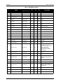
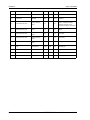
Input Commands
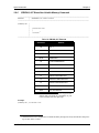
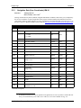
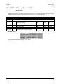
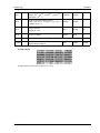
Table 5: SUPERSTAR II Binary Commands Summary
ID#
Definition
Message Typea
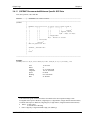
2
Reset receiver
CM
6
Request current channel assignment data
DR
20
Request navigation data (user coordinates)
DR
21
Request navigation data (ECEF coordinates)
DR
22
Request ephemeris data (ICD-GPS-200 format)
DR
23
Request measurement block data
DR
30
Set or Request receiver configuration
CM
33
Request satellite visibility, data and status
DR
43
Request DGPS configuration
DR
45
Request hardware/software identification
DR
47
Request base station status
DR
48
Request differential message status
DR
49
Request receiver status
DR
50
Request satellite health summary
DR
51
Initiate self-test
DR
63
Initiate Link
PM
64
Set channel deselection
CM
65
Request RTCM data message received
CM
67
Request SBAS data
DR
68
Request SBAS status message
DR
69
Set timing parameters
CM
75
Request ionospheric and UTC time data
DR
76
Request almanac data
DR
77
Update almanac
CM
78
Almanac data upload
CM
79
Specific almanac data upload
CM
80
Set position/operating mode
CM
81
Set mask angle
CM
83
Set DGPS configuration
CM
84
Set tropospheric/ionospheric model use
CM
86
Set mean sea level model use
CM
87
Set fixed height mode
CM
88
Select/define datum to use
CM
90
Set satellite deselection
CM
91
Set differential message configuration
CM
95
Request to track a particular satellite
CM
99
Erase NVM
CM
Continued on Page 25
24
SUPERSTAR II Firmware Reference Manual Rev 5
Input Commands
Chapter 2
ID#
103
Set date and time
CM
105
Set default binary message list
CM
110
Configure COM1 port mode
CM
113
Request timing Information
DR
a.
2.4
Message Typea
Definition
CM = Command Message, PM = Protocol Message and DR = Data Request
Factory Defaults
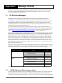
When the receiver is first powered up, or after an Erase NVM command (Message ID# 99 on Page 55),
commands revert to their factory default settings. Also, there are settings that depend on the receiver model, for
example, the baud rate at start-up.
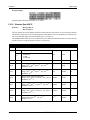
2.5
Binary Protocol Command Reference
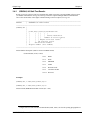
2.5.1
Reset Receiver ID# 2
This command performs a hardware reset if the password field (bytes 5-12) is valid.
BYTE
1-4
BIT
DESCRIPTION
UNITS
TYPE
Header, see Section 1.2.2, Message Block Structure starting on Page 13
5-12
Password:
UGPS-000 In ASCII format, U character first.
N/A
Uchar[8]
13-14
Checksum, see Section 1.6, Checksum
Calculation Rules starting on Page 19
N/A
Ushort
Example Input:
Reset
2.5.2
Request Current Channel Assignment Data ID# 6
This command may be used to request current channel assignment data. See also Message ID#s 6 and 7 output
starting on Page 77.
BYTE
1-4
5-6
BIT
DESCRIPTION
UNITS
TYPE
Header, see Section 1.2.2, Message Block Structure starting on Page 13
Checksum, see Section 1.6, Checksum
Calculation Rules starting on Page 19
N/A
Ushort
Example Input:
or:
SUPERSTAR II Firmware Reference Manual Rev 5
25
Chapter 2
2.5.3
Input Commands
Request Navigation Data (User Coordinates) ID# 20
This command requests navigation data with position and velocity in user coordinates of latitude, longitude and
height. See also Message ID# 20 output on Page 81.
BYTE
1-4
BIT
DESCRIPTION
UNITS
TYPE
Header, see Section 1.2.2, Message Block Structure starting on Page 13
Checksum, see Section 1.6, Checksum
Calculation Rules starting on Page 19
5-6
N/A
Ushort
Example Input:
or:
2.5.4
Request Navigation Data (ECEF Coordinates) ID# 21
This command requests navigation data with position and velocity in earth-centred-earth-fixed (ECEF)
coordinates of X, Y and Z. See also Message ID# 21 output on Page 83.
BYTE
1-4
5-6
BIT
DESCRIPTION
UNITS
TYPE
Header, see Section 1.2.2, Message Block Structure starting on Page 13
Checksum, see Section 1.6, Checksum
Calculation Rules starting on Page 19
N/A
Ushort
Example Input:
or:
26
SUPERSTAR II Firmware Reference Manual Rev 5
Input Commands
2.5.5
Chapter 2
Request Ephemeris Data (ICD-GPS-200 Format) ID# 22
Each time a new request is sent, the receiver sends a complete set of ephemeris and SV clock data currently
acquired. In continuous mode, the GPS receiver sends a complete set only on receipt of a new ephemeris. See
also Message ID# 22 output on Page 86.
BYTE
1-4
BIT
DESCRIPTION
UNITS
TYPE
Header, see Section 1.2.2, Message Block Structure starting on Page 13
Checksum, see Section 1.6, Checksum
Calculation Rules starting on Page 19
5-6
N/A
Ushort
Example Input:
or:
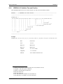
2.5.6
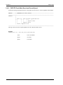
Request Measurement Block Data ID# 23
This command requests measurement block data for all tracked SVs. See also Message ID# 23 output on Page
87. Sending this message in One Shot mode, turns it off and does not return any data. To start or to turn this
message back on, send it in Continuous mode.
BYTE
1-4
BIT
UNITS
TYPE
Header, see Section 1.2.2, Message Block Structure starting on Page 13
0-1
5
2-7
6-7
DESCRIPTION
Message rate (see notebox below)
0: 1 Hz
1: 2 Hz
2: 5 Hz
3: Reserved
N/A
Reserved (set to 0)
N/A
Checksum, see Section 1.6, Checksum
Calculation Rules starting on Page 19
N/A
Uchar
Ushort
This command is not available unless your receiver has Carrier Phase Output (CP) capability. See also
Appendix A, SUPERSTAR II Card Models, starting on Page 133.
The rate you choose must match that of your receiver. For example, if your receiver is capable of 1 Hz,
choose 1 Hz in byte 5 above. If your receive is capable of 5 Hz then you can choose 1, 2 or 5 Hz.
Example Input:
SUPERSTAR II Firmware Reference Manual Rev 5
27
Chapter 2
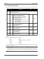
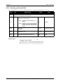
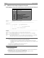
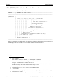
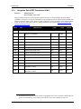
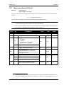
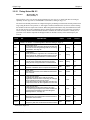
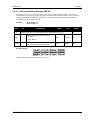
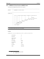
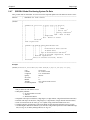
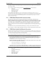
2.5.7
Input Commands
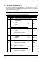
Set Receiver Configuration ID# 30
Use this command to change the configuration of your receiver. The characteristic defined in Table 6 on
Page 29 are not limits where the receiver stops functioning. They are rather limits within which the receiver
performance and behavior are optimal for the application. Exceeding these limits causes receiver performance
to degrade when used in the specified application.
See also Message ID# 30 output on Page 89.
1.
You must set the receiver configuration to match your application to get optimum performance.
2.
You must reboot your receiver for a new navigation rate to take effect.
BYTE
1-4
BIT
DESCRIPTION
UNIT
TYPE
Header, see Section 1.2.2, Message Block Structure starting on Page 13
0-3
5
4-7
0-1
6
Configuration:
0: User configuration
1: Man
2: Tractor
3: Marine
4: Car
5: Plane
6: Rocket
7-14: Reserved
15: Unlimited
N/A
Uchar
N/A
Uchar
N/A
Uchar
Reserved
Navigation messagea rate:
0: 1 Hz PVT
1: 2 Hz PVT
2: 5 Hz PVT
3: Reserved
Change is effective at the next power-up.
2-7
Reserved
0-1
Antenna type
0: Auto Detect b
1: Active
2: Passive
7
2-7
Reserved
8
Reserved
N/A
Uchar
9-10
Maximum velocity - this field is only read when
Byte 5 above is set to User configuration
m/s
Ushort
m/s2
Uchar
cm/s
Uchar
0-5
11
Maximum lateral acceleration in the range 0 to
40 m/s2 - this field is only read when Byte 5
above is set to User configuration
When 40 is set, the internal value is set to 39.2
6-7
12
Reserved
Stand still threshold - this field is only read when
Byte 5 above is set to User configuration
Continued on Page 29
28
SUPERSTAR II Firmware Reference Manual Rev 5
Input Commands
Chapter 2
13
Dead reckoning threshold
Range 0-254
255: use current value
s
Uchar
14-20
Reserved
N/A
Uchar[7]
21-22
Checksum, see Section 1.6, Checksum
Calculation Rules starting on Page 19
N/A
Ushort
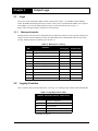
a.
b.
Navigation messages are NMEA GGA,GLL,GSA,RMC,VTG,906,907and Binary ID#s 20,21
Auto Detect starts up with a Passive setting, and auto switches to Active if an active
antenna is detected.
Example Input:
Set
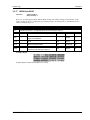
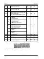
Table 6: Preset Configurations
Maximum Velocity
(m/s)
Maximum
Acceleration (m/s2)
Stand Still
Threshold (m/s)
Man
10
3
0.2
Car
45
8
0.2
Tractor
20
7
0.2
Marine
20
7
0.1
Plane
100
20
0.2
Rocket
510
40
0.2
Preset
Configuration
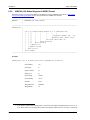
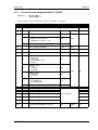
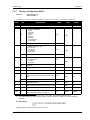
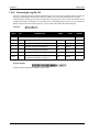
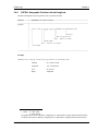
2.5.8
Request Receiver Configuration ID# 30
Use this command to obtain information on the configuration of your receiver. See also Set Receiver
Configuration on Page 28 and Message ID# 30 output on Page 89.
BYTE
1-4
5-6
BIT
DESCRIPTION
UNITS
TYPE
Header, see Section 1.2.2, Message Block Structure starting on Page 13
Checksum, see Section 1.6, Checksum
Calculation Rules starting on Page 19
N/A
Ushort
Example Input:
SUPERSTAR II Firmware Reference Manual Rev 5
29
Chapter 2
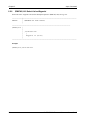
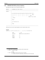
2.5.9
Input Commands
Request Satellite Visibility, Data and Status ID# 33
Use this command to request data and status information on satellites in view. See also Message ID# 33 output
on Page 90.
BYTE
1-4
BIT
DESCRIPTION
UNITS
TYPE
Header, see Section 1.2.2, Message Block Structure starting on Page 13
Checksum, see Section 1.6, Checksum
Calculation Rules starting on Page 19
5-6
N/A
Ushort
Example Input:
or:
2.5.10 Request DGPS Configuration ID# 43
Use this command to request information on the current DGPS configuration if your receiver is operating in
differential mode. See also Message ID# 43 output on Page 92 and Message ID# 83, Set DGPS Configuration
on Page 44.
BYTE
1-4
5-6
BIT
DESCRIPTION
UNITS
TYPE
Header, see Section 1.2.2, Message Block Structure starting on Page 13
Checksum, see Section 1.6, Checksum
Calculation Rules starting on Page 19
N/A
Ushort
Example Input:
or:
30
SUPERSTAR II Firmware Reference Manual Rev 5
Input Commands
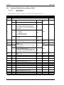
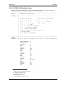
2.5.11
Chapter 2
Request Hardware/Software Identification ID# 45
Use this command to view your receiver’s software and hardware identification numbers and model. See also
Message ID# 45 output on Page 93.
BYTE
1-4
BIT
DESCRIPTION
UNITS
TYPE
Header, see Section 1.2.2, Message Block Structure starting on Page 13
Checksum, see Section 1.6, Checksum
Calculation Rules starting on Page 19
5-6
N/A
Ushort
Example Input:
2.5.12 Request Base Station Status ID# 47
This command allows you to request base station status information if your receiver is a BASE model and is
operating in differential mode. See also Message ID# 47 output on Page 94 and Appendix A, SUPERSTAR II
Card Models on Page 133.
BYTE
1-4
5-6
BIT
DESCRIPTION
UNITS
TYPE
Header, see Section 1.2.2, Message Block Structure starting on Page 13
Checksum, see Section 1.6, Checksum
Calculation Rules starting on Page 19
N/A
Ushort
Example Input:
or:
SUPERSTAR II Firmware Reference Manual Rev 5
31
Chapter 2
Input Commands
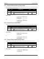
2.5.13 Request Differential Message Status ID# 48
Use this command to view the status of your differential messages if your receiver is operating in differential
mode. See also Message ID# 48 on Page 95.
BYTE
1-4
BIT
DESCRIPTION
UNITS
TYPE
Header, see Section 1.2.2, Message Block Structure starting on Page 13
Checksum, see Section 1.6, Checksum
Calculation Rules starting on Page 19
5-6
N/A
Ushort
Example Input:
or:
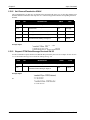
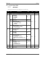
2.5.14 Request Receiver Status ID# 49
Use this command to obtain information on the status of your receiver. See also Message ID# 49 on Page 97.
BYTE
1-4
BIT
DESCRIPTION
UNITS
TYPE
Header, see Section 1.2.2, Message Block Structure starting on Page 13
Checksum, see Section 1.6, Checksum
Calculation Rules starting on Page 19
5-6
N/A
Ushort
Example Input:
or:
2.5.15 Request Satellite Health Summary ID# 50
Use this command to obtain satellite health information. See also Message ID# 50 output on Page 99.
BYTE
1-4
5-6
BIT
DESCRIPTION
UNITS
TYPE
Header, see Section 1.2.2, Message Block Structure starting on Page 13
Checksum, see Section 1.6, Checksum
Calculation Rules starting on Page 19
N/A
Ushort
Example Input:
32
SUPERSTAR II Firmware Reference Manual Rev 5
Input Commands
Chapter 2
or:
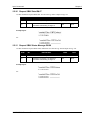
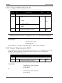
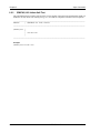
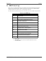
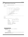
2.5.16 Initiate Self-Test ID# 51
This command allows you to initiate, or output the results of, a built-in status test. See also Message ID# 51
output on Page 101.
BYTE
BIT
DESCRIPTION
UNITS
1-4
Header, see Section 1.2.2, Message Block Structure starting on Page 13
5
0-7
6-7
TYPE
Built-in status test
0: Reserved
1: Initiate test
2: Output results
N/A
Uchar
Checksum, see Section 1.6, Checksum
Calculation Rules starting on Page 19
N/A
Ushort
Example Input:
2.5.17 Initiate Link ID# 63
See Section 1.3, Initiation starting on Page 17 for more on Message ID# 63.
BYTE
1-4
BIT
DESCRIPTION
UNITS
TYPE
Header, see Section 1.2.2, Message Block Structure starting on Page 13
5-12
Password (UGPS-000), in ASCII format, U
character first
N/A
Uchar[8]
13-14
Checksum, see Section 1.6, Checksum
Calculation Rules starting on Page 19
N/A
Ushort
Example Input:
Initiate link
SUPERSTAR II Firmware Reference Manual Rev 5
33
Chapter 2
Input Commands
2.5.18 Set Channel Deselection ID# 64
This command allows you idle up to 12 channels if the password field (bytes 5-12) is valid. The channels to be
disabled should be indicated in a bit map form. A 1 in the bit map specifies that the corresponding channel is
disabled.
BYTE
1-4
BIT
DESCRIPTION
UNITS
TYPE
Header, see Section 1.2.2, Message Block Structure starting on Page 13
5-12
Password (UGPS-000), in ASCII format, U
character first
N/A
Uchar[8]
13
bit map (bit 0: ch #1, bit 7: ch #8)
N/A
Uchar
14
bit map (bit 0: ch #9, bit 3: ch #12)
N/A
Uchar
15-16
Checksum, see Section 1.6, Checksum
Calculation Rules starting on Page 19
N/A
Ushort
Example Input:
Set
2.5.19 Request RTCM Data Message Received ID# 65
Use this command to request that the saved RTCM data processed by the receiver be output. See also Section
3.3.16, RTCM Data Message Received ID# 65 starting on Page 104.
BYTE
1-4
5-6
BIT
DESCRIPTION
UNITS
TYPE
Header, see Section 1.2.2, Message Block Structure starting on Page 13
Checksum, see Section 1.6, Checksum
Calculation Rules starting on Page 19
N/A
Ushort
Example Input:
or:
34
SUPERSTAR II Firmware Reference Manual Rev 5
Input Commands
Chapter 2
2.5.20 Request SBAS Data ID# 67
Use this command to request SBAS data. See also Message ID# 67 output on Page 105.
BYTE
1-4
BIT
DESCRIPTION
UNITS
TYPE
Header, see Section 1.2.2, Message Block Structure starting on Page 13
Checksum, see Section 1.6, Checksum
Calculation Rules starting on Page 19
5-6
N/A
Ushort
Example Input:
or:
2.5.21 Request SBAS Status Message ID# 68
Use this command to request SBAS status information. See also Message ID# 68 output on Page 106.
BYTE
1-4
5-6
BIT
DESCRIPTION
UNITS
TYPE
Header, see Section 1.2.2, Message Block Structure starting on Page 13
Checksum, see Section 1.6, Checksum
Calculation Rules starting on Page 19
N/A
Ushort
Example Input:
or:
SUPERSTAR II Firmware Reference Manual Rev 5
35
Chapter 2
Input Commands
2.5.22 Set Timing Parameters ID# 69
This command allows you to set timing parameters for receivers with Precise Timing (T) capability. If all ones
(F..Fh = 1111...1111) is entered in any field below, the corresponding value is not modified. See also Message
ID# 113, Time Status on Page 111 and Appendix A, SUPERSTAR II Card Models on Page 133.
BYTE
1-4
BIT
DESCRIPTION
UNITS
TYPE
Header, see Section 1.2.2, Message Block Structure starting on Page 13
5-8
Cable Delay
Set the propagation delay that is induced by the antenna
cable. This delay compensates the 1PPS output so it
remains synchronized with the UTC time. Range from 0
to +1 ms
ns
Ulong
9-12
1PPS Offset
Set the offset from the UTC time for the 1PPS signal to
be output. The offset is in the range 0 to 900 ms in steps
of 100 ms or it is not accepted.
ns
Ulong
13-16
1PPS Pulse Width
Range from 0 to 65 ms
100 ns
Ulong
N/A
Uchar
N/A
Uchar
17
18
0
Timing Mode:
Free-running
1
One Shot Alignment
The receiver slews the 1PPS output to align it with GPS
time once at power up. Afterwards, the 1PPS output is
synchronized using the receiver's internal clock and
therefore drifts. This mode is used for an externally
controlled oscillator.
2
Continuous Alignment
Keeps the 1PPS aligned on the GPS second boundary.
0
1PPS output continuously. This is the default for models
that do not have Precise Timing capability (T) and
cannot be changed.
1
1PPS output only when using at least one satellite in
navigation status
2
1PPS output only when acceptable conditions are met
according to the residual
3
Conditions 1 and 2 above
4
There is no 1PPS output
5
1PPS output (only when the receiver has a position, for
example, in Nav-3D or Diff-3D. This is the default for
models that do have Precise Timing capability and can
change.
6
Conditions 2 and 5 above
19
Reserved
N/A
Uchar
20-21
Intrinsic delay (range from 0 to 65534 ns)
65535 ns indicates no changes
ns
Ushort
Continued on Page 37
36
SUPERSTAR II Firmware Reference Manual Rev 5
Input Commands
Chapter 2
22-31
Reserved
N/A
Uchar[10]
32-33
Checksum, see Section 1.6, Checksum Calculation
Rules starting on Page 19
N/A
Ushort
Example Input:
Set
SUPERSTAR II Firmware Reference Manual Rev 5
37
Chapter 2
Input Commands
2.5.23 Request Ionospheric and UTC Time Data ID# 75
This command allows you to request ionospheric and UTC time information. See also Message ID# 75 output
on Page 107.
BYTE
1-4
BIT
DESCRIPTION
UNITS
TYPE
Header, see Section 1.2.2, Message Block Structure starting on Page 13
Checksum, see Section 1.6, Checksum
Calculation Rules starting on Page 19
5-6
N/A
Ushort
Example Input:
or:
2.5.24 Request Almanac Data ID# 76
This command allows you to request almanac data. See also Message ID# 76 output on Page 108.
BYTE
1-4
BIT
UNITS
TYPE
Header, see Section 1.2.2, Message Block Structure starting on Page 13
0
Output almanac? (set to 1)
1: Yes, request an almanac
1-7
Reserved (set to 0)
5
6-7
DESCRIPTION
Checksum, see Section 1.6, Checksum
Calculation Rules starting on Page 19
N/A
Uchar
N/A
Ushort
Example Input:
38
SUPERSTAR II Firmware Reference Manual Rev 5
Input Commands
Chapter 2
2.5.25 Update Almanac ID# 77
This command forces the decoding of a new almanac from SV subframe 4 and 5 data. See also Message ID# 76
input on Page 38 and output on Page 108.
BYTE
1-4
BIT
DESCRIPTION
UNITS
TYPE
Header, see Section 1.2.2, Message Block Structure starting on Page 13
Checksum, see Section 1.6, Checksum
Calculation Rules starting on Page 19
5-6
N/A
Ushort
Example Input:
2.5.26 Almanac Data Upload ID# 78
This command provides an almanac for the receiver if the password field (bytes 5-12) is valid. The data field of
the command is composed of a list of available SV#s (4 byte bit map) as well as the almanac data and week
common to all SVs. This command is sent ahead of the specific almanac data upload command (Message ID#
79 defined on Page 40). See also the Message ID# 78 log on Page 110.
BYTE
1-4
BIT
DESCRIPTION
UNITS
TYPE
Header, see Section 1.2.2, Message Block Structure starting on Page 13
5-12
Password (UGPS-000), in ASCII format, U
character first
N/A
Uchar[8]
13
bit map (bit 0: SV #1, bit 7: SV #8)
N/A
Uchar
14
bit map (bit 0: SV #9, bit 7: SV #16)
N/A
Uchar
15
bit map (bit 0: SV #17, bit 7: SV #24)
N/A
Uchar
16
bit map (bit 0: SV #25, bit 7: SV #32)
N/A
Uchar
17-18
Almanac week common to all SVs
Range: 0 to 65535
weeks
Ushort
19
Time of almanac common to all SVs
Range: 0 to 147
Resolution: 602112 / 4096
s
Uchar
20-21
Checksum, see Section 1.6, Checksum
Calculation Rules starting on Page 19
N/A
Ushort
Example Input:
SUPERSTAR II Firmware Reference Manual Rev 5
39
Chapter 2
Input Commands
2.5.27 Specific Almanac Data Upload ID# 79
This command provides SV-specific almanac data (using the YUMA almanac format) to the receiver. The first
data byte is the SV#. A complete series of these messages is sent in increasing SV# order, from 1 to 32, for the
SVs specified in the common almanac SV bit map data message. It is important to note that each specific data
message must be acknowledged (through Message ID #126, see Page 114) before sending the next specific
data message.
You must send Message ID# 78, see Page 39, before using this command.
If the GPS receiver does not receive all the SV specific almanac data messages specified in the common
message within 55 seconds then a time-out error occurs. The GPS receiver then disregards all the data currently
received and sends an unsuccessful status message to the PC. The PC resends the common message first, and
then all the data messages.
The GPS receiver always sends back an almanac reception status log whether the full almanac upload is
successful or not. The PC waits for this status log (or waits for the occurrence of a 60-second timeout period)
before requesting another almanac upload. Otherwise, the previous almanac upload is cancelled and the new
almanac upload request is ignored.
The almanac data specific to each SV is detailed below.
BYTE
1-4
BIT
DESCRIPTION
UNITS
TYPE
Header, see Section 1.2.2, Message Block Structure starting on Page 13
0-5
SV #
6-7
SV type
0: Reserved
1: GPS
2-3: Reserved
5
N/A
Uchar
6-13
Clock aging parameter, af0
Range: -2.010 - 2.0-20 to (2.010 - 1.0) - 2.0-20
Resolution: 2.0-20
s
Double
14-21
Clock aging parameter, af1
Range: -2.010 - 2.0-38 to (2.010 - 1.0) - 2.0-38
Resolution: 2.0-38
s/s
Double
22-29
Mean anomaly of reference time, M0
Range: -2.023 - 2.0-23 - π to (2.023 - 1.0) - 2.0-23- π
Resolution: 2.0-23 - π
radians
Double
30-37
Argument of perigee, W
Range: -2.023 - 2.0-23 - π to (2.023 - 1.0) - 2.0-23 - π
Resolution: 2.0-23 - π
radians
Double
38-45
Right ascension, Omega_0
Range: -2.023 - 2.0-23 - π to (2.023 - 1.0) - 2.0-23 - π
Resolution: 2.0-23 - π
radians
Double
46-53
Semi-major axis, Root_A
Range: 2525.0 to (2.024 - 1.0) - 2.0-11
Resolution: 2.0-11
m1/2
Double
Continued on Page 41
40
SUPERSTAR II Firmware Reference Manual Rev 5
Input Commands
Chapter 2
54-61
Rate of right ascension, Omega_Dot
Range: -2.015 - 2.0-38 - π to (2.015 - 1.0) - 2.0-38- π
Resolution: 2.0-38 - π
radians/s
Double
62-69
Angle of Inclination relative to 0.30π, i
range: -2.015 - 2.0-19 - π to (2.015 - 1.0) - 2.0-19 - π
resolution: 2.0-19 - π
radians
Double
70-77
Eccentricity, e
Range: 0 to 0.03
Resolution: 2.0-21
N/A
Double
78-79
Checksum, see Section 1.6, Checksum Calculation
Rules starting on Page 19
N/A
Ushort
Example Input:
SUPERSTAR II Firmware Reference Manual Rev 5
41
Chapter 2
Input Commands
2.5.28 Set Operating Mode ID# 80
This command allows you to set the receiver’s operating mode. See also Message ID# 47, Base Status on Page
94.
BYTE
1-4
BIT
DESCRIPTION
UNITS
TYPE
Header, see Section 1.2.2, Message Block Structure starting on Page 13
MSB of Message ID# byte:
0: command is executed normally
1: receiver position is cleared (command parameters are ignored)
5-12
Password (UGPS-XXX), in ASCII format, U character
first, where the command field XXX is:
000: Fix position (see bytes 13-36 below)
R00: Force to rover mode (position not saved)
GSP: Get survey position
B: Set base position and base information
S: Force to survey mode
If B or S above then YY where
YY: bytes 11-12 (Station ID and Station Health):
Bits 0-9: Station ID
Bits 10-12: Station health (as per RTCM-104)
Bits 13-15: Reserved
13-20
Interpretation depends on XXX in bytes 5-10 above
000 and BYY: Altitude ellipsoid
SYY: Desired survey time
R00 and GSP: N/A
m
or
hours
Double
21-28
Interpretation depends on XXX in bytes 5-10 above
000 and BYY: Latitude
SYY, R00 and GSP: N/A
radians
Double
29-36
Interpretation depends on XXX in bytes 5-10 above
000 and BYY: Longitude
SYY: Desired CEP
R00 and GSP: N/A
radians
or
m
Double
37-38
Checksum, see Section 1.6, Checksum Calculation
Rules starting on Page 19
N/A
N/A
Uchar[8]
Ushort
Example:
You can fix the position by setting the following values:
Bytes
[5-12]
[13-20]
[21-28]
[29-36]
Entry
UGPS-BYY | Station ID | Station Health
Altitude
Latitude
Longitude
When the receiver decodes this command, the latitude, longitude and altitude are saved in its NVM and static
mode is initiated immediately.
Self-Surveying Mode: You can end the surveying process by using the GSP command as indicated in the
command specification above (bytes 5-12). When the receiver decodes this command, it uses the current
averaged position and saves it to NVM without a station ID and Health Status. It then switches to static
mode.
42
SUPERSTAR II Firmware Reference Manual Rev 5
Input Commands
Chapter 2
Example Input:
Receiver position is not cleared
or:
Receiver position is cleared
2.5.29 Set Mask Angle ID# 81
This command allows you to set the mask angle. This value is stored in NVM. See also Message ID# 49,
Receiver Status on Page 97.
BYTE
1-4
BIT
DESCRIPTION
UNITS
TYPE
Header, see Section 1.2.2, Message Block Structure starting on Page 13
5-6
Mask angle (0 to π/2)
radians
Short
7-10
Reserved
N/A
Float
11-12
Checksum, see Section 1.6, Checksum
Calculation Rules starting on Page 19
N/A
Ushort
Example Input:
SUPERSTAR II Firmware Reference Manual Rev 5
43
Chapter 2
Input Commands
2.5.30 Set DGPS Configuration ID# 83
This command allows you to set the DGPS configuration if your receiver is operating in differential mode.
See also Message ID# 43, DGPS Status on Page 95.
BYTE
1-4
BIT
DESCRIPTION
UNITS
TYPE
Header, see Section 1.2.2, Message Block Structure starting on Page 13
0
Enable
0 = Off (Use SBAS over DGPS corrections)
1 = On (Use DGPS over SBAS corrections)
1-3
Reserved, should be 1
4-6
Reserved, should be 0
7
Port
0 = COM1
1 = COM2
5
N/A
Uchar
6
Differential coast time
seconds
Uchar
7
Reserved
N/A
Uchar
8
COM2 port baud rate
1 = 300
.
.
32 = 9600
.
.
64 = 19200
300 baud
Uchar
9-16
Reserved
N/A
Uchar[4]
Uchar[4]
Differential Mode
0 = No DGPS
1 = SBAS only
2 = DGPS only
3 = Select SBAS/DGPS automatically
N/A
Reserved
N/A
18-25
Reserved
N/A
Uchar[8]
26-27
Checksum, see Section 1.6, Checksum
Calculation Rules starting on Page 19
N/A
Ushort
0-1
17
2-7
Uchar
Example Input:
Set
44
SUPERSTAR II Firmware Reference Manual Rev 5
Input Commands
Chapter 2
2.5.31 Set Tropospheric/Ionospheric Model Use ID# 84
This command allows the receiver to use a tropospheric/ionospheric model correction if the password field
(bytes 5-12) is valid. The correction is applied by default (see the Warning below).
Sending this command with the MSB of the message ID byte to 0 ensures that tropospheric/ionospheric model
use is on. Setting the MSB of the message ID byte to 1 turns tropospheric/ionospheric model use off. See also
Message ID# 75, Ionospheric and UTC Data on Page 107.
Warning!: This command is for advanced users of GPS only. It is not recommended that you turn off the
tropospheric/ ionospheric model. The solution is seriously degraded with this model off.
BYTE
1-4
BIT
DESCRIPTION
UNITS
TYPE
Header, see Section 1.2.2, Message Block Structure starting on Page 13
MSB of Message ID# byte:
0: model is used
1: model is not used
5-12
Password (UGPS-000), in ASCII format,
U character first
N/A
Uchar[8]
13-14
Checksum, see Section 1.6, Checksum
Calculation Rules starting on Page 19
N/A
Ushort
Example Input:
Tropospheric/Ionospheric model use is on
SUPERSTAR II Firmware Reference Manual Rev 5
45
Chapter 2
Input Commands
2.5.32 Set Mean Sea Level Model Use ID# 86
This command allows you to use the mean sea level (MSL) model for your application if the password field
(bytes 5-12) is valid. Its use is Off by default. When it is On, the undulation value is automatically added.
Sending this command in One Shot mode turns MSL model use on and in Continuous mode turns it off.
BYTE
1-4
BIT
DESCRIPTION
UNITS
TYPE
Header, see Section 1.2.2, Message Block Structure starting on Page 13
MSB of Message ID# byte:
0: model is used
1: model is not used
5-12
Password (UGPS-000), in ASCII format,
U character first
N/A
Uchar[8]
13-14
Checksum, see Section 1.6, Checksum
Calculation Rules starting on Page 19
N/A
Ushort
Example Input:
Mean Sea Level model use is on
2.5.33 Set Fixed Height Mode ID# 87
This command is used to select a fixed mode. When NONE is selected, the receiver can not go in 2-D mode.
When AUTO is selected, the receiver automatically tries to go in 2-D mode if only 3 satellites are available.
This setting is stored in NVM.
BYTE
1-4
BIT
DESCRIPTION
UNITS
TYPE
Header, see Section 1.2.2, Message Block Structure starting on Page 13
0
5
1-7
Fixed Height Mode
0 = NONE (default)
1 = AUTO
N/A
Uchar
Reserved
6-13
Reserved
N/A
Double
14-15
Checksum
N/A
Ushort
Example Input:
Auto
None
2.5.34 Select/Define Datum to Use ID# 88
46
SUPERSTAR II Firmware Reference Manual Rev 5
Input Commands
Chapter 2
Use this command to select the datum used to report the position or to define a user-defined datum.
When byte 5 is set to 0, byte 6 must be 0 or in the range from 3 to 63 (dx, dy, dz are preset for these datums).
However, when byte 5 is set to 1 or 2, byte 6 must be 1 or 2 (user defined) and you must enter dx, dy, dz. See
Table 7 on Page 48.
The navigation data (user coordinates) Message ID# 20, see Section 3.3.3, Navigation Data (User
Coordinates) ID# 20 starting on Page 81, contains the datum currently in use.
BYTE
1-4
BIT
DESCRIPTION
UNITS
TYPE
Header, see Section 1.2.2, Message Block Structure starting on Page 13
5
Function
0: Select datum (bytes 7-36 are ignored)
1: Define a user-defined datum
2: Select and define a user-defined datum
N/A
Uchar
6
Datum number (from 0 to 63), see Table 7 on
Page 48
N/A
Uchar
7-8
dx
m
Short
9-10
dy
m
Short
11-12
dz
m
Short
13-20
A (semi-major)
m
Double
21-28
Inversed flattening (1/f)
N/A
Double
29-34
Reserved
N/A
Uchar[6]
35-36
Checksum, see Section 1.6, Checksum
Calculation Rules starting on Page 19
N/A
Ushort
Example Input:
Select/define a datum
SUPERSTAR II Firmware Reference Manual Rev 5
47
Chapter 2
Input Commands
Table 7: DATUM Description
#
NAME
0
WGS 1984
1
User Defined 1
2
User Defined 2
3
ELLIPSE
DX
Table 8 on Page 51
DY
DZ
COUNTRIES
WGS-84
0
0
0
Global definition
Adindan
Clarke_1880
-161
-14
205
Sudan
4
Arc 1950
Clarke_1880
-143
-90
-294
Botswana, Lesotho, Malawi,
etc.
5
Arc 1950
Clarke_1880
-169
-19
-278
Zaire
6
Arc 1960
Clarke_1880
-160
-6
-302
Kenya, Tanzania
7
Australian Geodetic 1984
Australian_National
-134
-48
149
Australia, Tasmania
8
Bogota Observatory
International
307
304
-318
Colombia
9
Campo Inchauspe
International
-148
136
90
Argentina
10
Cape
Clarke_1880
-136
-108
-292
South Africa
11
Carthage
Clarke_1880
-263
6
431
Tunisia
12
Chatham Island Astro 1971
International
175
-38
113
New Zealand (Chatham Island)
13
Chua Astro
International
-134
229
-29
Paraguay
14
Corrego Alegre
International
-206
172
-6
Brazil
15
European 1950
International
-87
-98
-121
Austria, Belgium, Denmark,
Finland, France, West
Germany, Gibraltar, Greece,
Italy, Luxembourg,
Netherlands, Norway,
Portugal, Spain, Sweden,
Switzerland
16
European 1950
International
-104
-101
-140
Cyprus
17
European 1950
International
-130
-117
-151
Egypt
18
European 1950
International
-86
-96
-120
England, Channel Islands,
Ireland, Scotland, Shetland
Islands
19
European 1950
International
-117
-132
-164
Iran
20
European 1950
International
-97
-88
-135
Italy (Sicily)
21
European 1979
International
-86
-98
-119
Austria, Finland, Netherlands,
Norway, Spain, Sweden,
Switzerland
22
Geodetic Datum 1949
International
84
-22
209
New Zealand
23
Hjorsey 1955
International
-73
46
-86
Iceland
24
Hong Kong 1963
International
-156
-271
-189
Hong Kong
Continued on Page 49
48
SUPERSTAR II Firmware Reference Manual Rev 5
Input Commands
Chapter 2
25
Hu-Tzu-Shan
International
-637
-549
-203
Taiwan
26
Indian 1954
Everest 1830
218
816
297
Thailand, Vietnam
27
Ireland 1965
Airy_modified
506
-122
611
Ireland
28
Kertau 1948
Everest 1948
-11
851
5
West Malaysia & Singapore
29
Liberia 1964
Clarke_1880
-90
40
88
Liberia
30
Luzon
Clarke_1866
-133
-77
-51
Philippines (Excluding
Mindanao)
31
Massawa
Bessel_1841
639
405
60
Ethiopia (Eritrea)
32
Merchich
Clarke_1880
31
146
47
Morocco
33
Minna
Clarke_1880
-92
-93
122
Nigeria
34
Nahrwan
Clarke_1880
-247
-148
369
Oman (Masirah Island)
35
North American 1927
Clarke_1866
-5
135
172
Alaska
36
North American 1927
Clarke_1866
-3
142
183
Antigua, Barbados, Bermuda,
Caicos Islands, Cuba,
Dominican Republic, Grand
Cayman, Jamaica, Turks
Islands
37
North American 1927
Clarke_1866
-10
158
187
Canada
38
North American 1927
Clarke_1866
-7
162
188
Canada (Alberta, British
Columbia)
39
North American 1927
Clarke_1866
-9
157
184
Canada (Manitoba, Ontario)
40
North American 1927
Clarke_1866
-22
160
190
Canada (New Brunswick,
Newfoundland, Nova Scotia,
Quebec)
41
North American 1927
Clarke_1866
4
159
188
Canada (Northwest Territories,
Saskatchewan)
42
North American 1927
Clarke_1866
-7
139
181
Canada (Yukon)
43
North American 1927
Clarke_1866
0
125
201
Canal zone
44
North American 1927
Clarke_1866
0
125
194
Central America
45
North American 1927
Clarke_1866
-12
130
190
Mexico
46
North American 1983
GRS-80
0
0
0
Alaska, Canada, CONUS,
Central America, Mexico
47
Old Egyptian 1907
Helmert_1906
-130
110
-13
Egypt
48
Old Hawaiian
Clarke_1866
61
-285
-181
Hawaii, Kauai, Maui, Oahu
49
Oman
Clarke_1880
-346
-1
224
Oman
50
Ord. Survey G. Britain
1936
Airy
375
-111
431
England, Isle of Man,
Scotland, Shetland Islands,
Wales
51
Pitcairn Astro 1967
International
185
165
42
Pitcairn Island
Continued on Page 50
SUPERSTAR II Firmware Reference Manual Rev 5
49
Chapter 2
50
Input Commands
52
Qatar National
International
-128
-283
22
Qatar
53
Qornoq
International
164
138
-189
Greenland (South)
54
Schwarzeck
Bessel_1841_in_
Namibia
616
97
-251
Namibia
55
South American 1969
South_America_
1969
-57
1
-41
Argentina, Bolivia, Brazil,
Chile, Colombia, Ecuador,
Guyana, Paraguay, Peru,
Trinidad & Tobago, Venezuela
56
South American 1969
South_America_
1969
-60
-2
-41
Brazil
57
South American 1969
South_America_
1969
-44
6
-36
Colombia
58
South American 1969
South_America_
1969
-45
8
-33
Venezuela
59
South Asia
Modified Fisher
1960
7
-10
-26
Singapore
60
Tananarive Observatory
1925
International
-189
-242
-91
Madagasgar
61
Tokyo
Bessel_1841
-148
507
685
Japan
62
Tokyo
Bessel_1841
-128
481
664
Mean Value
63
WGS 1972
WGS-72
0
0
0
Global definition
SUPERSTAR II Firmware Reference Manual Rev 5
Input Commands
Chapter 2
Table 8: Ellipsoid Description Table
Ellipsoid name
Semi-major axis (a)
Inverse flattening (1/f)
Airy
6377563.3960
299.324964600
Airy_modified
6377340.1890
299.324964600
Australian_National
6378160.0000
298.250000000
Bessel 1841
6377397.1550
299.152812800
Bessel 1841 in Namibia
6377483.8650
299.152812800
Clarke 1866
6378206.4000
294.978698200
Clarke 1880
6378249.1450
293.465000000
Everest (Sabah & Sarawak)
6377298.5560
300.801700000
Everest 1830
6377276.3450
300.801700000
Everest 1948
6377304.0630
300.801700000
Everest 1956
6377301.2430
300.801700000
Everest_Modified
6377304.0630
300.801700000
GRS-80
6378137.0000
298.257222101
Helmert 1906
6378200.0000
298.300000000
Hough
6378270.0000
297.000000000
International
6378388.0000
297.000000000
Krassovsky
6378245.0000
298.300000000
Modified Fisher 1960
6378155.0000
298.300000000
SGS 85
6378136.0000
298.257000000
South America 1969
6378160.0000
298.250000000
WGS-72
6378135.0000
298.260000000
WGS-84
6378137.0000
298.257223563
SUPERSTAR II Firmware Reference Manual Rev 5
51
Chapter 2
Input Commands
2.5.35 Satellite Deselection ID# 90
This command allows you to deselect SVs that you no longer wish to track if the password field (bytes 5-12) is
valid. The SVs are indicated in a bitmap form. A 1 in the bitmap specifies that the corresponding SV is
deselected and is not tracked.
BYTE
1-4
BIT
DESCRIPTION
UNITS
TYPE
Header, see Section 1.2.2, Message Block Structure starting on Page 13
5-12
Password (UGPS-XXX), in ASCII format, U
character first where XXX is:
000 - Deselect GPS SV
0G4 or 0G5 - Deselect SBAS SV
N/A
Uchar[8]
13
Dependant on XXX above
XXX = 000 = GPS SV
0 = SV #1
.
.
7 = SV #8
XXX = 0G5 = SBAS SV (such as WAAS or EGNOS)
0 = SV #129
.
.
7 = SV #136
N/A
Uchar
14
Also, dependant on XXX in bytes 5-12
XXX = 000 = GPS SV
0 = SV #9
.
.
7 = SV #16
XXX = 0G5 = SBAS SV (such as WAAS or EGNOS)
0 = SV #137
1-6 = Reserved
7 = SV #138
N/A
Uchar
15
Also, dependant on XXX in bytes 5-12
XXX = 000 = GPS SV
0 = SV #17
.
.
7 = SV #24
XXX = 0G4 = SBAS SV (such as WAAS or EGNOS)
0-6 = Reserved
7 = SV #120
N/A
Uchar
16
Also, dependant on XXX in bytes 5-12
XXX = 000 = GPS SV
0 = SV #25
.
.
7 = SV #32
XXX = 0G4 = SBAS SV (such as WAAS or EGNOS)
0 = SV #121
.
.
7 = SV #128
N/A
Uchar
17-18
Checksum, see Section 1.6, Checksum Calculation
Rules starting on Page 19
N/A
Ushort
Example Input:
52
SUPERSTAR II Firmware Reference Manual Rev 5
Input Commands
Chapter 2
2.5.36 Set Differential Message Configuration ID# 91
This command allows you to set the RTCM differential message type and rate if your receiver is a BASE model
and is operating in differential mode.
BYTE
1-4
BIT
DESCRIPTION
UNITS
TYPE
Header, see Section 1.2.2, Message Block Structure starting on Page 13
0-5
Message
0 = Clear all messages
1 = RTCM1
4 = RTCM3
6-7
Type
0: RTCM
1-3: Reserved
5
N/A
Uchar
6
Rate
0: Stop transmitting
1-255: Rate in seconds
s
Uchar
7-8
Checksum, see Section 1.6, Checksum
Calculation Rules starting on Page 19
N/A
Ushort
Example Input:
Set
SUPERSTAR II Firmware Reference Manual Rev 5
53
Chapter 2
Input Commands
2.5.37 Request to Track a Particular Satellite ID# 95
This command allows you to track an SV# on any available channel that is not currently tracking or that has not
been deselected. It starts the search at a given Doppler frequency offset to the carrier (Doppler center
frequency). The search window option is specified from 0 to 100 kHz in 1 kHz increments.
BYTE
1-4
BIT
DESCRIPTION
UNITS
TYPE
Header, see Section 1.2.2, Message Block Structure starting on Page 13
0-5
5
6-7
SV# (1 - 32) for GPS
or
SV# (33-51) for SBAS where
33 represents SV# 120
34 represents SV# 121
35 represents SV# 122
36 represents SV# 123
37 represents SV# 124
38 represents SV# 125
39 represents SV# 126
40 represents SV# 127
41 represents SV# 128
42 represents SV# 129
43 represents SV# 130
44 represents SV# 131
45 represents SV# 132
46 represents SV# 133
47 represents SV# 134
48 represents SV# 135
49 represents SV# 136
50 represents SV# 137
51 represents SV# 138
N/A
Uchar
SV type
0: Reserved
1: GPS
2: SBAS such as WAAS and EGNOS
6-9
Doppler center frequency:
Range: -60 000 to +60 000
Hz
Long
10
Search window size:
Range: 0 to +100 (1 kHz increments)
kHz
Uchar
11-14
Minimum C/No
Range: 0.0 to +63.0
dB-Hz
Float
15-16
Doppler
Hz/s
Ushort
17
Track command
0: auto (assign only if not already tracking)
1: manual (force to track on an idle channel)
N/A
Uchar
18-19
Checksum, see Section 1.6, Checksum
Calculation Rules starting on Page 19
N/A
Ushort
Example Input:
Track a particular satellite
54
SUPERSTAR II Firmware Reference Manual Rev 5
Input Commands
Chapter 2
2.5.38 Erase NVM ID# 99
This command erases the data contained in the EEPROM if the password field (bytes 5-10) is valid. You must
choose a value from Table 9 below.
BYTE
1-4
BIT
DESCRIPTION
UNITS
TYPE
Header, see Section 1.2.2, Message Block Structure starting on Page 13
5-10
Password (UGPS-0), in ASCII format,
U character first
N/A
Uchar[6]
11-12
Element to erase (00-20) in ASCII, see Table 9
N/A
Uchar[2]
13-14
Checksum, see Section 1.6, Checksum
Calculation Rules starting on Page 19
N/A
Ushort
Table 9: Element to Erase
Characters
00
Element
All
01-04
Reserved
05
Almanac
06-08
Reserved
09
TCXO parameters
10
IONO and UTC parameters
11
Position
12
Time
13
DGPS configuration
14
Default NMEA message list
15
RS232 configuration and
default binary message list
16-19
Reserved
20
Ephemeris
Example Input:
SUPERSTAR II Firmware Reference Manual Rev 5
55
Chapter 2
Input Commands
2.5.39 Set Date and Time ID# 103
This command allows you to set the date and time (UTC) if the password field (bytes 5-12) is valid.
BYTE
1-4
BIT
DESCRIPTION
UNITS
TYPE
Header, see Section 1.2.2, Message Block Structure starting on Page 13
Bytes 2 and 3: Reserved in this command
Password (UGPS-XXX), in ASCII format, U
character first where XXX is:
5-12
[000]: The date and time parameter is
applied
Hex
Uchar[8]
[100]: Requests a 1-shot 1PPS output and
sets the system time to provide date
and time if no SV is currently being
tracked
13-15
UTC time
Resolution: 1 s
h:min:s
Uchar:Uchar:Uchar
16-19
UTC date
Resolution: 1 day
dy:mo:yr
Uchar:Uchar:Ushort
20-21
Checksum, see Section 1.6, Checksum
Calculation Rules starting on Page 19
N/A
Ushort
Example Input:
Set
56
SUPERSTAR II Firmware Reference Manual Rev 5
Input Commands
Chapter 2
2.5.40 Set Default Binary Message List ID# 105
Use this command to set which logs to generate. Your selection is generated by default at start-up and comes
out at the highest rate possible.
BYTE
1-4
BIT
DESCRIPTION
UNITS
TYPE
Header, see Section 1.2.2, Message Block Structure starting on Page 13
0
Reserved
1
Message ID# 1 flag
0: Do not transmit
1: Transmit
2
Message ID# 2 flag
0: Do not transmit
1: Transmit
3-7
Message ID# 3-7 flags:
0: Do not transmit
1: Transmit
5
N/A
Uchar
6
Message ID#s 8 to 15 flags:
0: Do not transmit
1: Transmit
N/A
Uchar
7
.
.
20
As per Byte 6 for Message ID#s 16 to 23
.
.
As per Byte 6 for Message ID#s 120 to 127
N/A
Uchar
.
.
Uchar
21-28
Reserved
N/A
Uchar[8]
29-30
Checksum, see Section 1.6, Checksum
Calculation Rules starting on Page 19
N/A
Ushort
Example Input:
SUPERSTAR II Firmware Reference Manual Rev 5
57
Chapter 2
Input Commands
2.5.41 Configure COM1 Port Mode ID# 110
This command allows you to configure the baud rate and protocol of the COM1 port.
BYTE
1-4
BIT
DESCRIPTION
UNITS
TYPE
Header, see Section 1.2.2, Message Block Structure starting on Page 13
0-6
5
Baud rate in 300 baud units up to 19200
1: 300
.
.
32: 9600
.
.
64: 19200 (maximum)
N/A
Uchar
N/A
Ushort
Mode
0: NMEA
1: Binary
7
Checksum, see Section 1.6, Checksum
Calculation Rules starting on Page 19
6-7
If you enter a rate other than 300, 600, 1200, 2400, 4800, 9600, or 19200, the rate is rounded to the nearest
allowable baud rate by the receiver. For example, 0A = 1010 = 10 => 3000 is detected as 2400 by the
receiver.
Example Input:
In this example, C0 = 1100 0000 => Binary mode and 64 => Binary mode at 19200 baud
2.5.42 Request Timing Information ID# 113
This command allows you to request the timing status of your receiver if it is a SUPERSTAR II-based product
with Precise Timing (T) capability. See also Message ID# 113 output on Page 111 and Appendix A,
SUPERSTAR II Card Models on Page 133.
BYTE
1-4
5-6
BIT
DESCRIPTION
UNITS
TYPE
Header, see Section 1.2.2, Message Block Structure starting on Page 13
Checksum, see Section 1.6, Checksum
Calculation Rules starting on Page 19
N/A
Ushort
Example Input:
or:
58
SUPERSTAR II Firmware Reference Manual Rev 5
Input Commands
2.6
Chapter 2
NMEA Protocol Commands
Table 10 lists valid NMEA input sentences. An explanation of the supported NMEA protocol and field
definitions is provided in Appendix F, NMEA Format Data Messages on Page 150. Individual NMEA
commands and logs can be found in this chapter and Chapter 3 respectively.
The checksum is optional with NMEA commands.
For further details on the NMEA message structure and formats, please refer to NMEA 0183 specification.
The sentence type has the following meanings:
P-DR = Proprietary sentence issuing a data request
P-CM = Proprietary sentence issuing a command
Table 10: NMEA Input Commands
Identifier
Name
Type
Sentence Length
(Max Characters)
000
Configure COM1 port
P-CM
17
001
Initialize time and position
P-CM
77
003
Initiate BIT self test
P-CM
15
004
Request log
P-DR
19
005
Set output configuration
P-CM
67
007
Erase non-volatile memory (NVM)
P-CM
18
008
Set receiver parameters
P-CM
60
009
Define waypoint in MGRS format
P-CM
57
010
Select active waypoint
P-CM
18
012
Receiver configuration
P-CM
65
SUPERSTAR II Firmware Reference Manual Rev 5
59
Chapter 2
2.6.1
Input Commands
$PMCAG, 000 Configure COM1 Port Command
This command allows you to configure the baud rate and protocol (from NMEA to binary) of the COM1 port.
Use Message ID# 110 to switch back (from binary to NMEA), see Page 58. On power-up COM1 stays in the
same mode.
_________________________________________________________________________
HEADER
| CONTENTS OF DATA FIELDS
_________________________________________________________________________
$PMCAG,000 |
| ,x*hh<CR><LF>
|
|
|
Baud Rate Selection, see Table 11 below
_________________________________________________________________________
Table 11: Baud Rate Selection
Character
Baud Rate
0
19200
1
300
2
600
3
1200
4
2400
5
4800
6
9600
7
19200
Example:
Configure COM1 to binary mode at 19200.
$PMCAG,000,0*58<CR><LF>
60
SUPERSTAR II Firmware Reference Manual Rev 5
Input Commands
2.6.2
Chapter 2
$PMCAG, 001 Initialize Time and Position
This command initializes the receiver with reference UTC date, UTC time and user position.
_________________________________________________________________________
HEADER
| CONTENTS OF DATA FIELDS
___________________________________________________________________
$PMCAG,001 |
,xx,xx,xxxx,xx,xx,xx,±xx,xx,±llll.ll,a,yyyyy.yy,a,±x.xx*hh<CR><LF>
| | |
|
| |
| | |
| |
| |
| | |
|
| |
| | |
| |
| |
| | |
|
| |
| | |
| |
| altitude1
| | |
|
| |
| | |
| ---------- longitude-E/W2
| | |
|
| |
| | ---------- latitude-N/S3
| | |
|
| |
| reserved4
| | |
|
| |
reserved5
| | |
-------- time6
------- date7
_________________________________________________________________________
Example:
$PMCAG,001,08,07,1993,16,37,21,00,00,5301.97,N,00133.48,E,35.35*40<CR><LF>
Date
08/07/1993
Time
16:37:21
Reserved
Must be 00
Reserved
Must be 00
Latitude
53° 01.97' North
Longitude
1° 33.48' East
Altitude
35.35 m above mean sea level
1. Altitude in meters above (or below) mean sea level (resolution: 0.01 m)
2. Longitude - E/W with respect to WGS-84
3. Latitude - N/S with respect to WGS-84
4. Reserved, must be 00
5. Reserved, must be 00
6. UTC Time (Hour 0-23, Minutes 0-59, Seconds 0-59)
7. UTC Date (Day 1-31, Month 1-12, Year 1980-2079)
SUPERSTAR II Firmware Reference Manual Rev 5
61
Chapter 2
2.6.3
Input Commands
$PMCAG, 003 Initiate Self-Test
This command requests a complete self-test of the receiver. Results of the self-test are automatically output (see
$PMCAG, 902 Self-Test Results starting on Page 117) on COM1 at completion of the BIT self-test sequence.
_________________________________________________________________________
HEADER
| CONTENTS OF DATA FIELDS
_________________________________________________________________________
$PMCAG,003 |
|
| *hh<CR><LF>
|
_________________________________________________________________________
Example:
$PMCAG,003*47<CR><LF>
62
SUPERSTAR II Firmware Reference Manual Rev 5
Input Commands
2.6.4
Chapter 2
$PMCAG, 004 Request Log Command
This message requests only one transmission of the NMEA log you specify. See also Section 3.4, NMEA
Protocol Logs starting on Page 115 for a list of available NMEA logs.
_________________________________________________________________________
HEADER
| CONTENTS OF DATA FIELDS
_________________________________________________________________________
$PMCAG,004 |
|
| ,ccc*hh<CR><LF>
|
|
|
Sentence Identifier1
_________________________________________________________________________
Example:
Request a GPGGA log.
$PMCAG,004,GGA*2D<CR><LF>
1.
Valid sentence identifiers are those listed in Section 3.4, NMEA Protocol Logs starting on Page 115
SUPERSTAR II Firmware Reference Manual Rev 5
63
Chapter 2
2.6.5
Input Commands
$PMCAG, 005 Set Output Configuration Command
Use this command to configure the output of the COM1 port. It contains the input/output COM1 baud rate and
the list of Message IDs, see table below, with their minimum time interval between consecutive transmissions.
ID
Description
900
906
907
GGA
GLL
GSA
GSV
RMC
VTG
ZDA
Navigation Status
Bearing, Distance and Delta-Elevation to Waypoint
User Position in MGRS Format
Global Positioning System Fix Data
Geographic Position - Latitude/Longitude
GPS DOP and Active Satellites
GPS Satellites in View
Recommended Minimum Specific GPS Data
Track Made Good and Ground Speed
UTC Time and Date
_________________________________________________________________________
HEADER
| CONTENTS OF DATA FIELDS
_________________________________________________________________
$PMCAG,005 |
| ,x.x,ccc,xxx,...,ccc,xxxx*hh<CR><LF>
|
|
|
|
|
|
|
|
|
|
------ nth message block1
|
|
------ first message block1
|
baud rate2
_________________________________________________________________________
Example:
$PMCAG,005,4.8,GGA,010,RMC,001,VTG,001,ZDA,010*48<CR><LF>
Logs:
GGA and ZDA transmitted every 10 s, RMC and VTG transmitted every 1 s @4800 bps
$PMCAG,005,1,GLL,001*2A<CR><LF>
Logs:
GGA and ZDA transmitted every 10 s, GLL, RMC and VTG transmitted every 1 s @4800 bps
and stored in NVM: GLL,001 @ 4800 (overwrites all previous NVM messages)
1.
If the receiver is capable of navigating at a rate > 1Hz, enabling an NMEA message with a rate value
of 999 will request that message at the fastest rate possible provided that:
- the fastest rate has been set by Binary message 30 or NVM elements have been cleared
- the NMEA message is capable of the fastest rate. These include GGA, GLL, GSA, RMC, VTG,
906 and 907.
See also Table 19, SUPERSTAR II Software Models on Page 133.
2.
Messages can be stopped by entering a rate value of 0.
1. Each message block includes:
ccc: message identifier
xxx: time interval between consecutive transmissions (001to 999 s) where 000 stops the transmission
2. Valid baud rates: 0.3, 0.6, 1.2, 2.4, 4.8, 9.6, 19.2 (in KBaud units)
0: Keep same baud rate (no effect) and update message list with new update rate values
1: Save the included list in NVM and overwrite the previous one
64
SUPERSTAR II Firmware Reference Manual Rev 5
Input Commands
2.6.6
Chapter 2
$PMCAG, 007 Erase Non-Volatile Memory Command
_________________________________________________________________________
HEADER
| CONTENTS OF DATA FIELDS
_________________________________________________________________________
$PMCAG,007 |
|
| ,xx*hh<CR><LF>
|
|
|
element1
|
_________________________________________________________________________
Table 12: PMCAG, 007 Elements
Characters
00
01-04
05
06-08
ALL a
RESERVED
ALMANAC
RESERVED
09
TCXO PARAMETERS
10
IONO & UTC PARAMETERS
11
POSITION
12
TIME
13
DGPS CONFIGURATION
14
DEFAULT NMEA MSG LIST
15
RS232 CONFIGURATION a
W00 – W49
WXX
a.
Element
WAYPOINT ID
ALL WAYPOINTS
These commands force the receiver to go into the
default mode and baud rate (dependant on your
receiver model) at the next power-up.
Example:
$PMCAG,007,15*6B<CR><LF>
1. NVM element to erase: configuration of COM1 and binary message list sent by default after each powerup. See also Table 12 above.
SUPERSTAR II Firmware Reference Manual Rev 5
65
Chapter 2
2.6.7
Input Commands
$PMCAG, 008 Set Receiver Parameter Command
This command allows you to configure the parameters of your receiver.
_________________________________________________________________________
HEADER
| CONTENTS OF DATA FIELDS
_________________________________________________________________________
$PMCAG,008 |
|
| ,15,a,a,a,x.x,x,a,x,x.x,,x,x,,,,*hh<CR><LF>
|
| | | | | | | | | | | |
|
| | | | | | | | | | | UTC Time Resolution 1 2
|
| | | | | | | | | | Lat/Long Resolution 1 3
|
| | | | | | | | | Reserved 4
|
| | | | | | | | COM2 Port Baud Rate 5
|
| | | | | | | Differential Coast Time 1 6
|
| | | | | | DGPS Mode (E/D/W/B) 1
|
| | | | | Datum Number 7
|
| | | | Mask Angle 1 8
|
| | | Tropospheric/Ionospheric Model Use (E/D)
|
| | MSL Model Use (E/D)
|
| Reserved
|
Number of Elements 9
_________________________________________________________________________
Each of the parameters (except the number of elements) may be NULL, the associated receiver parameters are
left unchanged. The last four fields are reserved future use and are therefore also NULL.
Example:
1.
2.
3.
4.
5.
6.
7.
8.
9.
66
Stored in NVM
DGPS mode: E = enable, D = disable, W = SBAS only, B = DGPS only
This parameter controls the number of digits from the fraction part of the UTC Time data in all NMEA
messages. The default value is 2 and the range is 0 to 9.
This parameter controls the number of digits from the fraction part of the latitude and longitude data in
all NMEA messages. The default value is 4 and the range is 0 to 5.
Reserved field, null
Valid baud rates: 0.3, 0.6, 1.2, 2.4, 4.8, 9.6, 19.2 (in KBaud units)
0 - 255 seconds
This parameter is used to specify the datum that is used to express the position. See Table 7 on Page 48.
Value between 0.0 to 90.0°
This number indicates how many parameters are listed in the messages (15)
SUPERSTAR II Firmware Reference Manual Rev 5
Input Commands
Chapter 2
$PMCAG,008,15,E,E,,10.5,0,E,45,9.6,,,,,,,*37<CR><LF>
DGPS and MSL modes
Does not affect current Tropospheric/Ionospheric model status
Mask Angle: 10.5 °
Datum 0 - WGS 1984
DGPS Coast time: 45 seconds
DGPS Baud Rate: 9600 (COM2 port)
Does not affect present resolution on Latitude\Longitude and UTC time data
SUPERSTAR II Firmware Reference Manual Rev 5
67
Chapter 2
2.6.8
Input Commands
$PMCAG, 009 Define Waypoint in MGRS Format
Define the position of a waypoint in Military Grid Reference System (MGRS) format. Refer to http://earthinfo.nga.mil/GandG/grids/grids1.htm for more information on MGRS zone numbers.
_________________________________________________________________________
HEADER
| CONTENTS OF DATA FIELDS
|
_________________________________________________________________________
$PMCAG,009 |
|
| ,xx,a,a,a,xxxxx,xxxxx,±xxxxx.x,c--c,xx*hh<CR><LF>
|
| | | |
|
|
|
|
|
|
| | | |
|
|
|
| Waypoint number (00 - 49)
|
| | | |
|
|
|
Waypoint name (max 8 char)
|
| | | |
|
|
Altitude above MSL (m)
|
| | | |
|
Grid northing
|
| | | |
Grid easting
|
| | | Square row
|
| | Square column
|
| Zone letter
|
Zone number
_________________________________________________________________________
Example:
$PMCAG,009,18,T,X,R,02090,38779,100.5,POINTA,03*79<CR><LF>
1.
1.
68
Zone number
18 1
Zone letter
T
Square column
X
Square row
R
Grid easting
02090
Grid northing
38779
Altitude
100.5
Waypoint name
POINTA
Waypoint ID
03
If the Square Column field (latitude band) is X, then the Zone number field should not be set to 32, 34
or 36. These zones were incorporated into other zone numbers and do not exist, see Figure 1 following.
SUPERSTAR II Firmware Reference Manual Rev 5
Input Commands
Chapter 2
Figure 1: Example of Part of the MGRS Grid
SUPERSTAR II Firmware Reference Manual Rev 5
69
Chapter 2
2.6.9
Input Commands
$PMCAG, 010 Select Active Waypoint
Selects the active waypoint to be used in subsequent requests to $PMCAG, 906, see Page 118.
_________________________________________________________________________
|
HEADER
| CONTENTS OF DATA FIELDS
|
__________________________________________________________________
$PMCAG,010 |
|
| ,xx*hh<CR><LF>
|
|
|
Waypoint ID (00-49)
|
_________________________________________________________________________
Example:
$PMCAG,010,03*47<CR><LF>
70
SUPERSTAR II Firmware Reference Manual Rev 5
Input Commands
Chapter 2
2.6.10 $PCMAG, 012 Receiver Configuration
This message is used to configure the receiver for the following modes.
___________________________________________________________________________
HEADER
| CONTENTS OF DATA FIELDS
|
$PMCAG,012
|
|
|
,x,a,a,a,xxx,xx,x.xx,xxx,xxx,xxx,,,,,,,,*hh<CR><LF>
| | | |
| |
|
|
|
|
| | | |
| |
|
|
|
Filtering period in
|
|
|
| | | |
| | | |
| | | |
|
|
|
|
|
|
|
|
|
|
|
|
|
dynamic mode 1
|
Filtering period in
|
| | | |
|
|
|
|
static mode 2
|
|
| | | |
| | | |
|
|
|
|
|
|
Dead reckoning threshold (s) 3
|
|
| | | |
| | | |
|
|
|
|
Stand still threshold 3, 4
|
| | | |
|
Maximum accelaration (m/s2) 4, 5
|
| | | |
Maximum speed (m/s) 4
|
| | | Motion detector 6
|
| | Phase measurement type 7
| | Antenna type (P/A/F) 8
| Predefined configuration 9
1. 5..1270 seconds where 1275 sets the value to the predefined receiver parameters
2. 0.0 to 2.50 m/s
3. 0.0 to 2.55 m/s
4. This field is read only when User Configuration is chosen
5. 0 to 40
6. A: Automatic
S: Static
M: Motion
7. F: False
T: True
8. P: Auto Detect (starts with passive and switches to active if an active antenna in detected)
A: Active
F: Passive
9. 0: User Configuration
1: Man
2: Tractor
3: Marine
4: Car
5: Plane
6: Rocket
7-14: Reserved
15: Unlimited
SUPERSTAR II Firmware Reference Manual Rev 5
71
Chapter 2
Input Commands
Example 1:
$PMCAG,012,4,P,F,A,45,8,0.20,255,300,300,,,,,,,,*33<CR><LF>
Example 1 shows the default inputs in StarView.
Example 2:
$PMCAG,012,5,A,F,A,100,20,0.20,255,300,300,,,,,,,,*29<CR><LF>
In Example 2, the Antenna Type is Active and the Predefined Configuration is Plane.
Example 3:
$PMCAG,012,1,P,F,A,10,3,0.20,255,300,300,,,,,,,,*3D<CR><LF>
In Example 3, the Predefined Configuration is set to Man.
72
SUPERSTAR II Firmware Reference Manual Rev 5
Chapter 3
3.1
Output Logs
Logs
The receiver sends commands in Binary format as described in Chapter 1 or in NMEA format. In Binary
format, the MSB of the Message ID# may be used to set the receiver to Normal mode (MSB=0) or to Special
mode (MSB=1). See also the ID# description on Page 14 and Command Message on Page 15.
Binary format messages include a checksum for error checking.
3.1.1
Message Latencies
Message latency is the delay after a 1PPS mark and is an indication of when to expect a specific message to be
output. It refers to the time difference between the 1PPS and the time of transmission of the first byte of the
message. Message latencies for SSII are given in Table 13.
Table 13: Message Vs. Latency
Message
ID#
3.2
Definition
Mean
Latency (ms)
Standard
Deviation (ms)
20
Navigation data (user coordinates)
552.3
8.1
21
Navigation data (ECEF coordinates)
551.9
2.2
23
Measurement block data
155.1
3.5
33
Satellite visibility, data and status
751.6
2.2.1
113
Timing status
553.0
0.2
GGA
Global Positioning System fix data
550.4
0.2
GLL
Geographic position (lat/lon)
549.9
14.4
GSA
GPS DOP and active satellites
549.8
16.0
GSV
GPS satellites in view
50.5
2.6
VTG
Track made good and ground speed
550.5
0.2
ZDA
UTC time and date
150.8
0.7
Logs by Function
Table 14 lists the logs by function while Table 15 on Page 76 is a listing of logs in order of their Message IDs.
Table 14: Logs By Function Table
GENERAL RECEIVER CONTROL AND STATUS
Message
Definition
30
Receiver configuration
45
Hardware/software identification
49
Receiver status
51
Self-test results
113
Timing status
Continued on Page 73
SUPERSTAR II Firmware Reference Manual Rev 5
73
Chapter 3
Output Logs
POSITION, PARAMETERS, AND SOLUTION FILTERING
Message ID#
Definition
20
Navigation data (user coordinates)
21
Navigation data (ECEF coordinates)
22
Ephemeris data
23
Measurement block data
43
DGPS configuration
75
Ionospheric and UTC time data
GPGGA
NMEA, fix data, position data and undulation
GPGLL
NMEA, position data
GPGRS
NMEA, range residuals
GPGSA
NMEA, DOP information
CLOCK INFORMATION, STATUS, AND TIME
Message ID#
Definition
75
Ionospheric and UTC time data
113
Timing status
DIFFERENTIAL BASE STATION
Message ID#
Definition
33
Satellite data
43
DGPS configuration
47
Base station status
65
RTCM data message received
76
Almanac data
DIFFERENTIAL ROVER STATION
Message ID#
Definition
20
Navigation data (user coordinates)
21
Navigation data (ECEF coordinates)
23
Measurement block data
43
DGPS configuration
48
Differential message status
65
RTCM data message received
POST PROCESSING DATA
Message ID#
Definition
22
Ephemeris data
33
Satellite data
75
Ionospheric and UTC time data
113
Timing status
Continued on Page 75
74
SUPERSTAR II Firmware Reference Manual Rev 5
Output Logs
Chapter 3
SATELLITE TRACKING AND CHANNEL CONTROL
Message ID#
Definition
6
Current channel assignment (1-6)
7
Current channel assignment (7-12)
GPGSA
NMEA, SV DOP information
GPGSV
NMEA, satellite-in-view information
33
Satellite visibility, data and status
50
Satellite health summary
67
SBAS data
68
SBAS status message
76
Almanac data
78
Almanac reception status
NMEA Format Messages
Message ID#
Definition
900
Navigation status
902
Self-test results
906
Bearing, distance and delta-elevation to waypoint
907
User position - MGRS format
908
Receiver parameter status
912
Receiver configuration
GGA
GPS fix data and undulation
GLL
Geographic position - latitude/longitude
GSA
GPS DOP and active satellites
GSV
GPS satellites in view
RMC
GPS specific information
VTG
Track made good and ground speed
ZDA
UTC time and date information
WAYPOINT NAVIGATION
Message ID
Definition
20
Navigation data (user coordinates)
21
Navigation data (ECEF coordinates)
900
Navigation status
906
Bearing, distance and delta-elevation to waypoint
907
User position - MGRS format
SUPERSTAR II Firmware Reference Manual Rev 5
75
Chapter 3
Output Logs
Table 15: SUPERSTAR II Log Summary
ID#
Message Type a
6
Current channel assignment data (1-6)
UR/FR
7
Current channel assignment data (7-12)
UR/FR
20
Navigation data (user coordinates) b
UR/FR
21
Navigation data (ECEF coordinates) b
UR/FR
22
Ephemeris data (ICD-GPS-200 format) c
UR/FR
23
Measurement block data
UR/FR
30
Receiver configuration
DR/DM
33
Satellite visibility, data and status b
UR/FR
43
DGPS configuration
UR
45
Hardware/software identification
UR
47
Base station status data
DR/DM
48
Differential message status data
DR/DM
49
Receiver status data
DR/DM
50
Satellite health summary
UR/FR
51
Self-test results
DR/DM
65
RTCM data message received
67
SBAS data
DR/DM
68
SBAS status message
DR/DM
75
Ionospheric and UTC time data
DR/DM
76
Almanac data
DR/DM
78
Almanac reception status
113
Timing status
125
Link overload error log
PMd
126
Acknowledge log
PMd
a.
b.
c.
d.
76
Definition
FR
SMd
DR/DM
DM = Data Message, DR = Data Request, FR = First Request, PM = Protocol Message, SM = Status Message and UR = Update Request
Twice per second when in 2 Hz PVT mode
On first request and then on new ephemeris reception
PMs and SMs are output once per second or per 100 ms
SUPERSTAR II Firmware Reference Manual Rev 5
Output Logs
3.3
Chapter 3
Binary Protocol Logs
3.3.1
Current Channel Assignment Data (1-6) ID# 6
Structure:
Message ID#: 6
Rate (seconds): 1
This log shows you the current satellites assigned to channels 1 through 6.
BYTE
1-4
BIT
DESCRIPTION
UNIT
Header, see Section 1.2.2, Message Block Structure starting on Page 13
5
Reserved
N/A
0-4
SV # (0-31)
N/A
5
SV type
0: GPS SV, SV = bit 0-4 +1
1: SBAS SV, SV = bit 0-4 + 120
N/A
6-7
Reserved
N/A
7-10
Carrier frequency resolution
11-14
15-18
6
TYPE
OFFSET
0
Uchar
4
Uchar
5
cycles
Ulong
6
Serial to Noise ratio (SNR)
dB-Hz
Float
10
Reserved
N/A
Uchar[4]
14
0-1
Tracking state
0: not ready
1: bits ready
2: measurement ready
3: failed
N/A
2-3
Allocation state
0: idle
1: locating
2: tracking
N/A
Uchar
18
4
Channel mode
1: automatic
0: manual
N/A
5
SNR level
0: old SNR levels
1: new SNR levels
N/A
6-7
Reserved
N/A
19
20-33
Channel 2 assignment data
19
34-47
Channel 3 assignment data
33
48-61
Channel 4 assignment data
62-75
Channel 5 assignment data
61
76-89
Channel 6 assignment data
75
90-91
Checksum, see Section 1.6, Checksum
Calculation Rules starting on Page 19
SUPERSTAR II Firmware Reference Manual Rev 5
As per Channel 1
N/A
Ushort
47
89
77
Chapter 3
Output Logs
Example Output:
Example header translated to decimal: 01 06 249 85
78
SUPERSTAR II Firmware Reference Manual Rev 5
Output Logs
3.3.2
Chapter 3
Current Channel Assignment Data (7-12) ID#7
Structure:
Message ID#: 7
Rate (seconds): 1
This log shows you the current satellites assigned to channels 7 through 12.
BYTE
1-4
BIT
DESCRIPTION
UNIT
Header, see Section 1.2.2, Message Block Structure starting on Page 13
5
Reserved
N/A
0-4
SV # (0-31)
N/A
5
SV type
0: GPS SV, SV = bit 0-4 +1
1: SBAS SV, SV = bit 0-4 + 120
N/A
6-7
Reserved
N/A
7-10
Carrier frequency resolution
11-14
15-18
6
TYPE
OFFSET
0
Uchar
4
Uchar
5
cycles
Ulong
6
SNR
dB-Hz
Float
10
Reserved
N/A
Uchar[4]
14
0-1
Tracking state
0: not ready
1: bits ready
2: measurement ready
3: failed
N/A
2-3
Allocation state
0: idle
1: locating
2: tracking
N/A
Uchar
18
4
Channel mode
1: automatic
0: manual
N/A
5
SNR level
0: old SNR levels
1: new SNR levels
N/A
6-7
Reserved
N/A
19
20-33
Channel 8 assignment data
19
34-47
Channel 9 assignment data
33
48-61
Channel 10 assignment data
62-75
Channel 11 assignment data
61
76-89
Channel 12 assignment data
75
90-91
Checksum, see Section 1.6, Checksum
Calculation Rules starting on Page 19
SUPERSTAR II Firmware Reference Manual Rev 5
As per Channel 7
N/A
Ushort
47
89
79
Chapter 3
Output Logs
Example Output:
Example header translated to decimal: 01 07 248 85
80
SUPERSTAR II Firmware Reference Manual Rev 5
Output Logs
3.3.3
Chapter 3
Navigation Data (User Coordinates) ID# 20
Structure:
Message ID#: 20
Rate (seconds): 1, 0.2 or 0.5 1
This log contains the best position (latitude, longitude and altitude coordinates) and velocity (m/s) computed by
the receiver. In addition, it reports height and velocity Figures of Merit (FOMs) and a Dilution of Precision
value (DOP), which are quality indicators. For more information on the FOM and DOP, refer to the Glossary in
the GPS+ Reference Manual available on our website at http://www.novatel.com/Downloads/docupdates.html.
BYTE
1-4
BIT
DESCRIPTION
UNITS
Header, see Section 1.2.2, Message Block Structure starting on Page 13
0-4
UTC time: hours
hours
5
Time not corrected by UTC parameters:
1 = True
0 = False
N/A
6-7
Reserved
N/A
6
UTC time: minutes
7-14
5
TYPE
OFFSET
0
Uchar
4
minutes
Uchar
5
UTC time: seconds
s
Double
6
15
UTC date: day
day
Uchar
14
16
UTC date: month
month
Uchar
15
17-18
UTC date: year
year
Ushort
16
19-26
Latitude
Range: -π/2 to π/2
radians
Double
18
27-34
Longitude
Range: -π to π
radians
Double
26
35-38
Altitude
m
Float
34
39-42
Ground speed
m/s
Float
38
43-46
Track angle
Range: -π to π
radians
Float
42
47-50
North velocity
m/s
Float
46
51-54
East velocity
m/s
Float
50
55-58
Vertical velocity
m/s
Float
54
59-62
HFOM
m
Float
58
63-66
VFOM
m
Float
62
67-68
HDOP
Resolution: 0.1 units
N/A
Ushort
64
Continued on Page 82
1. SUPERSTAR II-based receivers are capable of a navigation rate of 1 Hz. If you have a model with 5 Hz
PVT, you can alternatively select 5 Hz (0.2) or 2 Hz (0.5). See a list of models on Page 133.
SUPERSTAR II Firmware Reference Manual Rev 5
81
Chapter 3
Output Logs
VDOP
Resolution: 0.1 units
69-70
0-4
5
Solution confidence level
0: Normal (NAV solution from < 5 SVs)
1: High (NAV solution from ≥ 5 SVs)
6
Differential source selection
0: SBAS
1: DGPS
7
Reserved
0-3
Number of SVs used to compute this solution
4-7
Coordinate system (lowest nibble)
Datum number b3,b2,b1,b0
0-3
System mode
0: Self test
1: Initialization
2: Acquisition
3: Navigation
4: Fault
4-5
Coordinate system (highest nibble)
Datum number b5,b4
6
Satellite tracking mode
0: All SVs in view (based on current almanac,
position and time)
1: Sky search
7
Coordinate system (highest nibble)
Datum number b6 (b7 = 0)
72
73
Ushort
68
N/A
Uchar
70
N/A
Uchar
71
N/A
Uchar
72
hours
Uchar
73
Uchar
74
Ushort
75
NAV Mode
0: Initialization required
1: Initialized
2: NAV 3-D
3: Altitude hold (NAV 2-D)
4: Differential 3-D
5: Differential 2-D
6: Dead reckoning
With Base Station Mode only:
8: Base station
71
N/A
74
Elapsed time since power up (hours)
75
Reserved
76-77
Checksum, see Section 1.6, Checksum
Calculation Rules starting on Page 19
N/A
Example Output:
Example header translated to decimal: 01 20 235 71
82
SUPERSTAR II Firmware Reference Manual Rev 5
Output Logs
3.3.4
Chapter 3
Navigation Data (ECEF Coordinates) ID# 21
Structure:
Message ID#: 21
Rate (seconds): 1, 0.2 or 0.5 1
This log contains the receiver’s best available position and velocity in earth-centered-earth-fixed (ECEF)
coordinates (see Figure 2 on Page 85). In addition, it reports height and velocity Figures of Merit (FOMs) and
Dilution of Precision (DOP) values, which are quality indicators. For more information on the FOM and DOP,
refer to the Glossary in the GPS+ Reference Manual available on our website at http://www.novatel.com/
Downloads/docupdates.html.
BYTE
1-4
BIT
DESCRIPTION
UNITS
TYPE
Header, see Section 1.2.2, Message Block Structure starting on Page 13
OFFSET
0
5-12
GPS Time
Range: 0.0 to 604800.0
s
Double
4
13-14
Week
weeks
Short
12
15-22
X coordinate position
m
Double
14
23-30
Y coordinate position
m
Double
22
31-38
Z coordinate position
m
Double
30
39-42
Velocity vector along X-axis
m/s
Float
38
43-46
Velocity vector along Y-axis
m/s
Float
42
47-50
Velocity vector along Z-axis
m/s
Float
46
51-58
Clock bias
s
Double
50
59-66
Clock drift
s/s
Double
58
67-70
HFOM
m
Float
66
71-74
VFOM
m
Float
70
75-76
HDOP
Resolution: 0.1 units
N/A
Ushort
74
77-78
VDOP
Resolution: 0.1 units
N/A
Ushort
76
Continued on Page 84
1. SUPERSTAR II-based receivers are capable of a navigation rate of 1 Hz. If you have a model with 5 Hz
PVT, you can alternatively select 5 Hz (0.2) or 2 Hz (0.5). See a list of models on Page 133.
SUPERSTAR II Firmware Reference Manual Rev 5
83
Chapter 3
Output Logs
0-4
NAV Mode
0: Initialization required
1: Initialized
2: NAV 3-D
3: Altitude hold (NAV 2-D)
4: Differential 3-D
5: Differential 2-D
6: Dead reckoning
For BASE model units:
8: Base Station
79
5
Solution Confidence Level
0: Normal (NAV solution from < 5 SVs)
1: High (NAV solution from ≥ 5 SVs)
6
Differential source selection
0: SBAS
1: DGPS
7
Reserved
0-3
Number of SVs used to compute this solution
4-7
Reserved
80
N/A
Uchar
78
N/A
Uchar
79
81-83
Reserved
N/A
Uchar[3]
80
84-85
Checksum, see Section 1.6, Checksum
Calculation Rules starting on Page 19
N/A
Ushort
84
Example Output:
Example header translated to decimal: 01 21 234 79
84
SUPERSTAR II Firmware Reference Manual Rev 5
Output Logs
Chapter 3
- Definitions Origin =
*
Earth's center of mass
Z-Axis =
Parallel to the direction of the Conventional Terrestrial Pole (CTP) for
polar motion, as defined by the Bureau International de l'Heure (BIH) on
the basis of the coordinates adopted for the BIH stations.
X-Axis =
Intersection of the WGS 84 Reference Meridian Plane and the plane of
the CTP's Equator, the Reference Meridian being parallel to the Zero
Meridian defined by the BIH on the basis of the coordinates adopted for
the BIH stations.
Y -Axis =
Completes a right-handed, earth-centered, earth-fixed (ECEF)
orthogonal coordinate system, measured in the plane of the CTP
Equator, 90 East of the X-Axis.
BIH - Defined CTP
(1984.0)
Z
WGS 84
ω
Earth's Center
of Mass
BIH-Defined
Zero Meridian
(1984.0)
Y
WGS 84
X
WGS 84
*
Analogous to the BIH Defined Conventional Terrestrial System (CTS), or BTS,
1984.0.
Figure 2: ECEF Coordinate System
SUPERSTAR II Firmware Reference Manual Rev 5
85
Chapter 3
3.3.5
Output Logs
Ephemeris Data ID# 22
Structure:
Message ID#: 22
Rate (seconds): 1
This log contains ephemeris data for one satellite at a rate of one log per second until the ephemeris data list is
complete, and then only if there is new ephemeris data. Please refer to the NAVSTAR GPS Space Segment/
Navigation Interface document ICD-GPS-200 Rev. B for specifics on the format of the ephemeris data. See
Table 1 on Page 12 for contact information.
BYTE
1-4
BIT
DESCRIPTION
UNITS
TYPE
Header, see Section 1.2.2, Message Block Structure starting on Page 13
OFFSET
0
0-4
SV# (0-31)
N/A
5-7
Reserved
N/A
6-77
Ephemeris sub-frame 1-3/words 3-10
MSB of byte 6 is Bit 61 of subframe 1
as per NAVSTAR a
5
78-79
Checksum, see Section 1.6, Checksum
Calculation Rules starting on Page 19
N/A
77
5
Uchar
a.
Ushort
4
See Reference [1] on Page 12
Example Output:
Example header translated to decimal: 01 22 233 73
86
SUPERSTAR II Firmware Reference Manual Rev 5
Output Logs
3.3.6
Chapter 3
Measurement Block Data ID# 23
Structure:
Message ID#: 23
Rate (seconds): 1, 0.2 or 0.5 1
This log contains raw data carrier phase and code phase data. If measurement blocks exist, the total length of
the log is:
15 + 11*N Measurement Block + 2
Otherwise, the total length of the log is 6 bytes (the header plus the checksum only).
1.
Please also read the Measurements appendix starting on Page 138 of this manual for more details on
raw code phase measurements and raw carrier phase measurements.
2.
This log is only available on GPS receiver models that have Carrier Phase Output (CP) capability. See
also Appendix A, SUPERSTAR II Card Models, starting on Page 133.
BYTE
BIT
1-4
DESCRIPTION
UNITS
TYPE
Header, see Section 1.2.2, Message Block Structure starting on Page 13
5
Time slew value
0-2
6
3-7
Time Status
0: Unknown
1: Not Set
2: Coarse (25 x 10-6 s Variance)
3: Fine (1 x 10-14 s Variance)
OFFSET
0
175ns
Uchar
4
N/A
Uchar
5
Reserved
7
Number of measurement blocks
N/A
Uchar
6
8-15
Predicted GPS time
This is the time when the measurement
samples have been taken at the receiver (not
the transmission time).
s
Double
7
N/A
Uchar
15
0.25 dB/Hz
Uchar
16
16
0-5
SV# (0-31)
6
Reserved
7
Toggle at each ephemeris transmission
Signal-to-Noise ratio (SNR). For example, a
value of 160 translates to 40.0 dB/Hz
17
Continued on Page 88
1.
SUPERSTAR II-based receivers with a carrier phase (CP) option are capable of 1 Hz output. If you
have a 5 Hz CP model, you can also select 5 Hz (0.2) or 2 Hz (0.5). See a list of models on Page 133.
SUPERSTAR II Firmware Reference Manual Rev 5
87
Chapter 3
Output Logs
Code phase
The correlator aligns the locally generated
satellite C/A with the received signal using a
precision of 1/1024 of a half chip. A chip lasts
for 1/1023 ms Therefore, the code phase
precision is 1/1023 ms/2/1024.
Range: 0 to 2095103999
18-21
0-1
Carrier Phase
0: Ready
1: Phase Ambiguous
2: Phase Unlock
3: Not Ready
1/1024 half
chip
17
Uchar[4]
21
Uchar
25
N/A
For most applications, use measurements only
when both bits 0 and 1 are clear. See Section
C.4, Carrier Phase In Message ID# 23 starting
on Page 141.
22-25
Ulong
2-11
Carrier Phase
Range: 0-1023
cycles
12-31
Integrated number of cycles
Range: Natural roll over
cycles
Cycle_Slip Counter. Raw data and tracking
loop slips are observable in the measurement.
The carrier tracking loop has a 180° ambiguity
so it is possible to slip by a full cycle or a half
cycle. The half cycles are detected and
signalled through the measurements qualifiers
(least significant 2 bits of the carrier phase).
N/A
26
Cycle_Slip Counter Increments by 1 every time
a cycle slip is detected during a 10 ms period
Range: natural roll over
Range for BASE model units: loss of carrier
continuity and number of GPS data parity errors
27...
Measurement block #2
.
.
Measurement block #N
As per Measurement Block #1
(bytes 16-26 above)
Next SV offset = 15 + (#SVs x 11)
28-29
Checksum, see Section 1.6, Checksum
Calculation Rules starting on Page 19
N/A
Ushort
variable
Example Output:
Example Header Translated to Decimal: 01 23 232 110
88
SUPERSTAR II Firmware Reference Manual Rev 5
Output Logs
3.3.7
Chapter 3
Receiver Configuration ID# 30
Structure:
Message ID#: 30
Rate (seconds): 1
Use this log to view the receiver configuration parameters. See also Page 28 to set the configuration.
BYTE
1-4
BIT
DESCRIPTION
UNITS
TYPE
Header, see Section 1.2.2, Message Block Structure starting on Page 13
Predefined configuration:
0: User configuration
1: Man
2: Tractor
3: Marine
4: Car
5: Plane
6: Rocket
7-14: Reserved
15: Unlimited
N/A
4-7
Reserved
N/A
0-1
Navigation messagea rate:
0: 1 Hz PVT
1: 2 Hz PVT
2: 5 Hz PVT
3: Reserved
N/A
2-7
Reserved
N/A
0-1
Antenna type
0: Auto Detect b
1: Active
2: Passive
N/A
0-3
5
6
7
2-7
Reserved
9-10
Maximum speed
m/s
Maximum acceleration in the range 0 to 40 m/s
When 40 is received, the internal value is set to
39.2
m/s2
11
6-7
0
Uchar
4
Uchar
5
Uchar
6
Uchar
7
Ushort
8
Uchar
10
Reserved
8
0-5
OFFSET
Reserved
12
Standstill threshold
cm/s
Uchar
11
13
Dead reckoning threshold in the range 0 to 254
s
Uchar
12
14-20
Reserved
Uchar[7]
13
21-22
Checksum, see Section 1.6, Checksum
Calculation Rules starting on Page 19
Ushort
variable
a.
b.
N/A
Navigation messages are NMEA GGA, GLL, GSA, RMC, VTG and Binary ID#s 20 and 21
Auto Detect starts up with a Passive setting, and auto switches to Active if an active antenna is
detected.
Example Output:
Example Header Translated to Decimal: 01 30 225 16
SUPERSTAR II Firmware Reference Manual Rev 5
89
Chapter 3
3.3.8
Output Logs
Satellite Visibility Data and Status ID# 33
Structure:
Message ID#: 33
Rate (seconds): 1
Data transmission of up to 12 satellites in view listed in decreasing elevation order.
BYTE
1-4
BIT
DESCRIPTION
UNITS
TYPE
Header, see Section 1.2.2, Message Block Structure starting on Page 13
0-3
Total number of satellites in view
N/A
4-7
Reserved
N/A
0-4
SV# (0 - 31) for GPS
If this value is 0 and Byte 9, bits 1-7 are nonzero, see Byte 9 below for the SBAS SV#
If Byte 9, bits 1-7 are zero, add 1 to the SV# to
get the PRN
N/A
5-6
SV status
0 = In view
1 = Tracking
2 = Measurement ready
3 = Used by navigation
N/A
7
Differential corrections available
0 = Off
1 = On
N/A
Elevation
Range: -90 to +90
degree
Azimuth
Range: 0 to 360
The azimuth value is from bits 0 to 7 of byte 8
and bit 0 of byte 9
degree
Non-zero = SBAS SV (33-51)
Add this value to 87 to get the true SBAS SV#
For example, 33 represents SBAS SV# 120
(Byte 6, bits 0-4 above will be zero in this case)
N/A
10
SNR
Range: 0 to 90
11-15
5
OFFSET
0
Uchar
4
Uchar
5
Char
6
Char
7
Char
8
dB
Uchar
9
Satellite visibility data of the 2nd SV
as per SV1
as per SV1
10
16-20
Satellite visibility data of the 3rd SV
as per SV1
as per SV1
15
21-25
Satellite visibility data of the 4th SV
as per SV1
as per SV1
20
26-30
Satellite visibility data of the 5th SV
as per SV1
as per SV1
25
31-35
Satellite visibility data of the 6th SV
as per SV1
as per SV1
30
36-40
Satellite visibility data of the 7th SV
as per SV1
as per SV1
35
41-45
Satellite visibility data of the 8th SV
as per SV1
as per SV1
40
46-50
Satellite visibility data of the 9th SV
as per SV1
as per SV1
45
6
7
8
0-7
0
9
1-7
Continued on Page 91
90
SUPERSTAR II Firmware Reference Manual Rev 5
Output Logs
Chapter 3
51-55
Satellite visibility data of the 10th SV
as per SV1
as per SV1
50
56-60
Satellite visibility data of the 11th SV
as per SV1
as per SV1
55
61-65
Satellite visibility data of the 12th SV
as per SV1
as per SV1
60
66-67
Checksum, see Section 1.6, Checksum
Calculation Rules starting on Page 19
N/A
Ushort
65
Example Output:
Example Header Translated to Decimal: 01 33 222 61
SUPERSTAR II Firmware Reference Manual Rev 5
91
Chapter 3
3.3.9
Output Logs
DGPS Configuration ID# 43
Structure:
Message ID#: 43
Rate (seconds): 1
This log outputs the current DGPS configuration if your receiver is operating in differential mode.
BYTE
1-4
BIT
DESCRIPTION
UNITS
TYPE
Header, see Section 1.2.2, Message Block Structure starting on Page 13
0
Enable
0 = Off (Use SBAS over DGPS corrections)
1 = On (Use DGPS over SBAS corrections)
1-3
Mode
0 = No DGPS
1 = SBAS only
2 = DGPS only
3 = DGPS/SBAS automatically
5
4-6
Reserved: must be 0
7
Port
0: COM1
1: COM2
OFFSET
0
N/A
Uchar
4
6
Differential coast time
seconds
Uchar
5
7
Reserved
N/A
Uchar
6
8
Baud rate (1=300, ... 32=9600, ... 64=19200)
bauds
Uchar
7
N/A
Uchar[8]
8
9-25
Reserved
N/A
Uchar[8]
16
N/A
Ushort
25
26-27
Checksum, see Section 1.6, Checksum
Calculation Rules starting on Page 19
Example Output:
Example Header Translated to Decimal: 01 43 212 21
92
SUPERSTAR II Firmware Reference Manual Rev 5
Output Logs
Chapter 3
3.3.10 Hardware/Software Identification ID# 45
Structure:
Message ID#: 45
Rate: one shot
This log provides software identification information.
BYTE
1-4
BIT
DESCRIPTION
UNITS
TYPE
Header, see Section 1.2.2, Message Block Structure starting on Page 13
OFFSET
0
5-18
Operational software part number
N/A
Uchar[14]
4
19-32
Model part number, for example:
169-613955-XXX
where XXX is the Configuration Block Number,
see also Appendix A, SUPERSTAR II Card
Models, starting on Page 133.
N/A
Uchar[14]
18
33-36
Model checksum
N/A
Uchar[4]
32
37-50
Boot S/W part number
N/A
Uchar[14]
36
51-73
Reserved
N/A
Uchar[22]
50
74-86
Product serial number (PSN)
N/A
Uchar[13]
73
87-90
Reserved
N/A
Uchar[4]
86
91-94
Boot checksum
Hex
Short
90
95-98
Operational checksum
Hex
Short
94
System type
0 - 2 = Reserved
3 = SUPERSTAR II
N/A
Uchar
98
N/A
Ushort
99
0-2
99
3-7
100101
Reserved
Checksum, see Section 1.6, Checksum
Calculation Rules starting on Page 19
Example Output:
Example Header Translated to Decimal: 01 45 210 95
SUPERSTAR II Firmware Reference Manual Rev 5
93
Chapter 3
3.3.11
Output Logs
Base Station Status Data ID# 47
Structure:
Message ID#: 47
Rate (seconds): 1
This log contains the position of the base station as received through RTCM messages if your receiver is a
BASE model and is operating in differential mode. It also has a time tag, the status of the base station, and the
RTCM messages in use and their rates. This information is set at the base station using Message ID# 80, Set
Operating Mode and Message ID# 91, Differential Message Status. See Page 42 and Page 53 respectively for
details on these commands.
BYTE
1-4
BIT
DESCRIPTION
UNITS
TYPE
Header, see Section 1.2.2, Message Block Structure starting on Page 13
0-1
Base Status
0: Not in base
1: Position not initialized
2: Base initialized
3: Reserved
2-4
Baud Rate
0: 300
1: 600
2: 1200
3: 2400
4: 4800
5: 9600
6: 19200
N/A
5-7
Reserved
N/A
6-13
Time remaining in survey
14-17
5
OFFSET
0
N/A
Uchar
4
hours
Double
5
Base station position CEP
meters
Float
13
18-25
Base station position latitude
radians
Double
17
26-33
Base station position longitude
radians
Double
25
34-41
Base station position height
meters
Double
33
42-45
Reserved
N/A
Uchar[4]
41
0-4
Number of differential messages to follow
N/A
Uchar
45
5-7
Reserved
N/A
47
Message type
N/A
Uchar
46
48
Message rate
s
Uchar
47
46
Next message
variable
Variable
Checksum, see Section 1.6, Checksum
Calculation Rules starting on Page 19
N/A
Ushort
Variable
Example Output:
Example Header Translated to Decimal: 01 47 208 42
94
SUPERSTAR II Firmware Reference Manual Rev 5
Output Logs
Chapter 3
3.3.12 Differential Message Status ID# 48
Structure:
Message ID#: 48
Rate (seconds): 1
This log outputs the status of the differential message requested by Message ID# 48 if your receiver is a BASE
model or is operating as a rover in differential mode. See also Appendix A, SUPERSTAR II Card Models,
starting on Page 133.
If the unit is in rover mode the fields in Table 16 are used. However, if the unit is in base mode, the fields in
Table 17 on Page 96 are used. Set the operating mode using Message ID# 80, Set Operating Mode, see Page
42.
Table 16: Rover Message ID# 48
BYTE
1-4
BIT
DESCRIPTION
UNITS
TYPE
Header, see Section 1.2.2, Message Block Structure starting on Page 13
5
Station identification number
N/A
0-1
Reserved
N/A
2-4
Station health
N/A
5-6
Station identification bit
N/A
7
Reserved
N/A
7-10
Message received bitmap
0
= RTCM1
1
= RTCM2
2
= RTCM3
3-7
= Reserved
8
= RTCM9
11-14
OFFSET
0
Uchar
4
Uchar
5
=
Uchar[4]
6
Reserved
N/A
Uchar[4]
10
15-16
Differential data link - valid word count
N/A
Uchar[2]
14
17-18
Differential data link - parity error count
N/A
Uchar[2]
16
19-24
Reserved
N/A
Uchar[6]
18
0-12
Receiver mode
bits 0-12: ZCount of last message 1, 2, or 9
N/A
Uchar[2]
24
13-15
DGPS Status
0: DGPS disabled
1: Initialization/synchronization
2: Correcting
3: Bad GDOP
4: Old corrections
5: Station unhealthy
6: Too few SVs
7: Reserved
N/A
27-28
Reserved
N/A
Uchar[2]
26
29-30
Checksum, see Section 1.6, Checksum
Calculation Rules starting on Page 19
N/A
Ushort
28
6
25-26
SUPERSTAR II Firmware Reference Manual Rev 5
95
Chapter 3
Output Logs
Table 17: Base Message ID# 48
BYTE
1-4
BIT
DESCRIPTION
UNITS
TYPE
Header, see Section 1.2.2, Message Block Structure starting on Page 13
5
Station identification number (bits 0-7)
N/A
0-1
Reserved
N/A
2-4
Station health
N/A
5-6
Station identification bit
N/A
7
Reserved
N/A
7-10
Message received bitmap
0 = RTCM1
1 = Reserved
2 = RTCM3
11-24
OFFSET
0
Uchar
4
Uchar
5
N/A
Uchar[4]
6
Reserved
N/A
Uchar[14]
10
ZCount of last message 1, 2, or 9
N/A
Ushort
24
27-28
Reserved
N/A
Uchar[2]
26
29-30
Checksum, see Section 1.6, Checksum
Calculation Rules starting on Page 19
N/A
Ushort
28
6
25-26
0-12
Example Output:
Example Header Translated to Decimal: 01 48 207 24
96
SUPERSTAR II Firmware Reference Manual Rev 5
Output Logs
Chapter 3
3.3.13 Receiver Status ID# 49
Structure:
Message ID#: 49
Rate (seconds): 1
This log provides information on the configuration of your GPS receiver.
BYTE
1-4
BIT
DESCRIPTION
UNITS
Header, see Section 1.2.2, Message Block Structure starting on Page 13
0-3
System mode
0: Self test
1: Initialization
2: Acquisition
3: Navigation
4: Fault
N/A
4-5
Reset source
N/A
6
Satellite tracking mode
0: All SVs in view (based on
current almanac, position
and time)
1: Sky search
N/A
7
NVM controller state
0: Idle (no process in progress)
1: Busy (erase and/or store data
process in progress)
N/A
0
Tropospheric model
0: Enabled
1: Disabled
N/A
1
MSL model
0: Enabled
1: Disabled
N/A
2-3
Last power-up modes
0: Cold start (invalid almanac,
time or position)
1: Initialized start (valid almanac,
time and position) only with battery backup
RAM
N/A
4
Reserved
N/A
5-7
Time source
0: Initialization required
1: External
2: SV without NAV mode
3: SV with NAV mode
N/A
7-8
Almanac week of collection
9-10
Week number
5
6
TYPE
OFFSET
0
Uchar
4
Uchar
5
N/A
Ushort
6
N/A
Ushort
8
Continued on Page 98
SUPERSTAR II Firmware Reference Manual Rev 5
97
Chapter 3
Output Logs
0-31
SV deselect bitmap
Byte 11: bit 0 = SV1
.
.
.
Byte 14: bit 7 = SV32
N/A
Uchar[4]
10
0-11
Channel deselection bitmap
Byte 15: bit 0 = Ch1
.
.
.
Byte 16: bit 7 = Ch12
N/A
Uchar[2]
14
17
Reserved
N/A
Uchar
16
18-21
SBAS SV disable
bit 0 = SV120 and so on
N/A
Uchar[4]
17
22
Minimum idle time
%
Uchar
21
23
Idle time
%
Uchar
22
24-25
Mask angle
0.01°
Short
23
Discretes
0: DISC_IP1
1: DISC_IP2
2: DISC_IP3
3: DISC_IO1
4: DISC_IO2 (position valid output only pin)
5: DISC_IO3
N/A
Uchar
25
Reserved
N/A
27-33
Reserved
N/A
Uchar[7]
26
34
NAV mode
0: Initialization required
1: Initialized
2: NAV 3-D
3: Altitude hold (2-D)
4: Differential 3-D
5: Differential 2-D
6: Dead reckoning
7: Reserved
8: Base station
N/A
Uchar
33
35-40
Reserved
N/A
Uchar[6]
34
41-42
Differential word count
N/A
Ushort
40
43-44
Parity error count
N/A
Ushort
42
45-46
Checksum, see Section 1.6, Checksum
Calculation Rules starting on Page 19
N/A
Ushort
44
11-14
15-16
0-5
26
6-7
Example Output:
Example Header Translated to Decimal: 01 49 206 40
98
SUPERSTAR II Firmware Reference Manual Rev 5
Output Logs
Chapter 3
3.3.14 Satellite Health Summary ID# 50
Structure:
Message ID#: 50
Rate (seconds): 30
This log indicates the health of each GPS satellite.
BYTE
1-4
BIT
DESCRIPTION
UNITS
TYPE
Header, see Section 1.2.2, Message Block Structure starting on Page 13
0-1
SV #1
0: Healthy
1: Unhealthy
6-7
SV #4
0: Healthy
1: Unhealthy
N/A
0-1
SV #5
0: Healthy
1: Unhealthy
N/A
6-7
SV #8
0: Healthy
1: Unhealthy
N/A
0-1
SV #9
0: Healthy
1: Unhealthy
N/A
6-7
SV #12
0: Healthy
1: Unhealthy
N/A
0-1
SV #13
0: Healthy
1: Unhealthful
N/A
6-7
SV #16
0: Healthy
1: Unhealthy
N/A
0-1
SV #17
0: Healthy
1: Unhealthy
N/A
6-7
SV #20
0: Healthy
1: Unhealthy
N/A
0-1
SV #21
0: Healthy
1: Unhealthy
N/A
6-7
SV #24
0: Healthy
1: Unhealthy
OFFSET
0
N/A
5
6
7
8
9
10
Uchar
4
Uchar
5
Uchar
6
Uchar
7
Uchar
8
Uchar
9
N/A
Continued on Page 100
SUPERSTAR II Firmware Reference Manual Rev 5
99
Chapter 3
Output Logs
0-1
SV #25
0: Healthy
1: Unhealthy
6-7
SV #28
0: Healthy
1: Unhealthy
N/A
0-1
SV #29
0: Healthy
1: Unhealthy
N/A
6-7
SV #32
0: Healthy
1: Unhealthy
N/A
Checksum, see Section 1.6, Checksum
Calculation Rules starting on Page 19
N/A
N/A
11
12
13-14
Uchar
10
Uchar
11
Ushort
44
Example Output:
Example Header Translated to Decimal: 01 50 205 08
100
SUPERSTAR II Firmware Reference Manual Rev 5
Output Logs
Chapter 3
3.3.15 Self-Test Results ID# 51
Structure:
Message ID#: 51
Rate (seconds): 1
This log outputs the results of an initiated built-in test (BIT) request.
BYTE
1-4
BIT
DESCRIPTION
UNITS
TYPE
Header, see Section 1.2.2, Message Block Structure starting on Page 13
Bit copy of the initiated BIT request message
0: Reserved
1: Initiated BIT result
2: Power up BIT result
5
0
RAM
0: Fail
1: Pass
1
Flash
0: Fail
1: Pass
2
EEPROM
0: Fail
1: Pass
3
UART
0: Fail
1: Pass
4
Real time clock
0: Fail
1: Pass
5
Correlator and RF
0: Fail
1: Pass
6-7
Reserved
6
7-9
Reserved
0
Boot software checksum
0: Pass
1: Fail
1
Operation software checksum
0: Pass
1: Fail
2-4
Flash error code. If different from 000, the
receiver cannot be reset.
0: Pass
1: Fail
5-6
Flash ID
7
Flash size OK and software supported
0: Flash OK
1: Flash bad
10
OFFSET
0
N/A
Uchar
4
N/A
Uchar
5
N/A
Uchar[3]
6
N/A
Uchar
9
Continued on Page 102
SUPERSTAR II Firmware Reference Manual Rev 5
101
Chapter 3
Output Logs
0
EEPROM status link error
0: Pass
1: Fail
1
Memory location error
0: Pass
1: Fail
2-7
Reserved
0
COM1 port (UART) serial link
0: Pass
1: Not ready or busy
1
TX flag
0: Full
1: Not full
2
Internal loop tests data
0: Received
1: Not received
3
Framing or parity
0: Pass
1: Fail
4
RX flag
0: Full
1: Not full
5
Overrun test
0: Pass
1: Fail
6-7
Reserved
11
12
COM2 port (UART) results
(see the byte 12 description above)
13
0-2
bit 0: Link timeout
0: Pass
1: Error
bit 1: Clock date error
0: Pass
1: Error
bit 2: Clock time error
0: Pass
1: Error
3-4
Scratch pad error
bit 3:
0: Pass
1: Error
bit 4:
Reserved
5-7
Reserved
14
N/A
Uchar
10
N/A
Uchar
11
Hex
Uchar
12
N/A
Uchar
13
Continued on Page 103
102
SUPERSTAR II Firmware Reference Manual Rev 5
Output Logs
Chapter 3
0
RF MAG LO limit
0: Pass
1: Error
1
RF MAG HI limit
0: Pass
1: Error
2
RF SIGN LO limit
0: Pass
1: Error
3
RF SIGN HI limit
0: Pass
1: Error
4
RF I and Q test
0: Pass
1: Error
5
RF PLL
0: Locked
1: Not Locked
6-7
Reserved
15
N/A
Uchar
14
16
Global correlator test results #1
Bit 0: Channel 0 error in I and Q test
.
.
Bit 7: Channel 7 error in I and Q test
N/A
Uchar
15
17
Global correlator test results #2
Bit 0: Channel 0 error in I and Q test
.
.
Bit 7: Channel 7 error in I and Q test
N/A
Uchar
16
18
Global correlator test results #3
Bit 0: Channel 9 error in I and Q test
Bit 1: Channel 10 error in I and Q test
Bit 2: Channel 11 error in I and Q test
Bit 3: Channel 12 error in I and Q test
Bit 4: Channel 9 error in Measurement test
Bit 5: Channel 10 error in Measurement test
Bit 6: Channel 11 error in Measurement test
Bit 7: Channel 12 error in Measurement test
N/A
Uchar
17
19-40
Reserved
N/A
Uchar[22]
18
41-42
Checksum, see Section 1.6, Checksum
Calculation Rules starting on Page 19
N/A
Ushort
40
Example Output:
Example Header Translated to Decimal: 01 51 204 36
SUPERSTAR II Firmware Reference Manual Rev 5
103
Chapter 3
Output Logs
3.3.16 RTCM Data Message Received ID# 65
Structure:
Message ID#: 65
Rate (seconds): 1
This message shows the saved RTCM data processed by the receiver. The RTCM Frame in this log is the same
RTCM frame that the rover received, see Reference [2] on Page 12 for the interface rules.
BYTE
1-4
BIT
DESCRIPTION
UNITS
TYPE
OFFSET
Header, see Section 1.2.2, Message Block Structure starting on Page 13
5
Control fixed at 0x00
N/A
Uchar
4
6-n
RTCM frame data
N/A
String
Variable
variable
(n+1, n+2)
Checksum, see Section 1.6, Checksum
Calculation Rules starting on Page 19
N/A
Ushort
Variable
Example Output:
Example Header Translated to Decimal: 01 65 190 58
104
SUPERSTAR II Firmware Reference Manual Rev 5
Output Logs
Chapter 3
3.3.17 SBAS Data ID# 67
Structure:
Message ID#: 67
Rate (seconds): 1
Bytes 21 - 52 of this log provide the 250-bit SBAS message. The 250-bit message is packed into a 32-byte
frame. See also Section D.2.1, SBAS Messages starting on Page 146 and Appendix A, SUPERSTAR II Card
Models, starting on Page 133.
BYTE
1-4
BIT
DESCRIPTION
UNITS
TYPE
OFFSET
Header, see Section 1.2.2, Message Block Structure starting on Page 13
5-8
Week number
N/A
Ulong
4
9-16
GPS time
range: 0.0 to 604800.0
s
Double
8
17-20
SV ID
N/A
Ulong
16
21-52
SBAS message data field
N/A
Uchar [32]
20
53-54
Checksum, see Section 1.6, Checksum
Calculation Rules starting on Page 19
N/A
Ushort
52
Example Output:
Example Header Translated to Decimal: 01 67 188 48
SUPERSTAR II Firmware Reference Manual Rev 5
105
Chapter 3
Output Logs
3.3.18 SBAS Status Message ID# 68
Structure:
Message ID#: 68
Rate (seconds): 1
This log provides the status of the SBAS (for example WAAS and EGNOS) message.
BYTE
1-4
BIT
DESCRIPTION
UNITS
TYPE
Header, see Section 1.2.2, Message Block Structure starting on Page 13
OFFSET
0
5-6
Message count
N/A
Ushort
2
7
SV ID
N/A
Uchar
6
8
SBAS message number
N/A
Uchar
7
9
Correction age
seconds
Uchar
8
10-11
Reserved
N/A
Uchar[2]
9
12-13
Checksum, see Section 1.6, Checksum
Calculation Rules starting on Page 19
N/A
Ushort
11
Example Output:
Example Header Translated to Decimal: 01 68 187 07
106
SUPERSTAR II Firmware Reference Manual Rev 5
Output Logs
Chapter 3
3.3.19 Ionospheric and UTC Time Data ID# 75
Structure:
Message ID#: 75
Rate (seconds): 1
This log outputs Ionospheric Model parameters and UTC Time parameters.
BYTE
1-4
BIT
DESCRIPTION
UNITS
TYPE
Header, see Section 1.2.2, Message Block Structure starting on Page 13
OFFSET
0
5
a0: Alpha parameter constant term
Char
4
6
a1: Alpha parameter 1st order term
Char
5
7
a2: Alpha parameter 2nd order term
Char
6
8
a3: Alpha parameter 3rd order term
Char
7
9
a0: Beta parameter constant term
Char
8
10
a1: Beta parameter 1st order term
Char
9
11
a2: Beta parameter 2nd order term
Char
10
12
a3: Beta parameter 3rd order term
Char
11
13
Is the Ionospheric data valid?
0 = Not valid
1 = Valid
Uchar
12
14
a0: 2nd alpha parameter constant term
Ulong
13
15
a1: 2nd alpha parameter 1st order term
Ulong
14
16
DTLS: delta time due to leap seconds
Char
15
17
TOT: reference time of UTC parameters
Uchar
16
18
WNT: UTC reference week number
Uchar
17
19
WNLSF: Future week number
Uchar
18
20
DN: Day number
Uchar
19
21
DTLSF: Future delta time due to leap seconds
Char
20
22
Is the UTC data valid?
0 = Not valid
1 = Valid
Uchar
21
23-38
Reserved
Uchar[16]
22
39-40
Checksum, see Section 1.6, Checksum
Calculation Rules starting on Page 19
Ushort
38
SUPERSTAR II Firmware Reference Manual Rev 5
N/A
107
Chapter 3
Output Logs
Example Output:
Example Header Translated to Decimal: 01 75 180 40
3.3.20 Almanac Data ID# 76
Structure:
Message ID#: 76
Rate (seconds): 1
This log contains the decoded almanac parameters from subframes four and five as received from the satellite
with the parity information removed and appropriate scaling applied. For more information on Almanac data,
refer to the GPS SPS Signal Specification (Reference [1] on Page 12).
The SUPERSTAR II family of receivers automatically saves almanac information in their non-volatile memory
(NVM), therefore creating an almanac boot file is not necessary.
BYTE
1-4
BIT
DESCRIPTION
UNITS
TYPE
OFFSET
Header, see Section 1.2.2, Message Block Structure starting on Page 13
0-5
SV# (1 -31)
N/A
Uchar
4
6-7
SV type
0: Reserved
1: GPS
2: Reserved
6-9
Almanac reference time, TOA
s
Ulong
5
10-13
Clock aging parameter, af0
Range: -2.010 - 2.0-20 to (2.010 - 1.0) - 2.0-20
Resolution: 2.0-20
s
Ulong
9
14-21
Clock aging parameter, af1
Range: -2.010 - 2.0-38 to (2.010 - 1.0) - 2.0-38
Resolution: 2.0-38
s/s
Double
13
22-29
Mean anomaly of reference time, M0
Range: -2.023 - 2.0-23 - π to (2.023 - 1.0) - 2.0-23- π
Resolution: 2.0-23 - π
radians
Double
21
30-37
Argument of perigee, W
Range: -2.023 - 2.0-23 - π to (2.023 - 1.0) - 2.0-23 - π
Resolution: 2.0-23 - π
radians
Double
29
38-45
Right ascension, Omega_0
Range: -2.023 - 2.0-23 - π to (2.023 - 1.0) - 2.0-23 - π
Resolution: 2.0-23 - π
radians
Double
37
46-53
Semi-major axis, Root_A
Range: 2525.0 to (2.024 - 1.0) - 2.0-11
Resolution: 2.0-11
m1/2
Double
45
5
Continued on Page 109
108
SUPERSTAR II Firmware Reference Manual Rev 5
Output Logs
Chapter 3
54-61
Rate of right ascension, Omega_Dot
Range: -2.015 - 2.0-38 - π to (2.015 - 1.0) - 2.0-38- π
Resolution: 2.0-38 - π
radians/s
Double
53
62-69
Angle of Inclination relative to 0.30π, i
range: -2.015 - 2.0-19 - π to (2.015 - 1.0) - 2.0-19 - π
resolution: 2.0-19 - π
radians
Double
61
70-77
Eccentricity, e
Range: 0 to 0.03
Resolution: 2.0-21
N/A
Double
69
78-79
Almanac week common to all SVs
Range: 0 to 65535
weeks
Short
77
80...
Next satellite block
variable
Checksum, see Section 1.6, Checksum Calculation
Rules starting on Page 19
variable
N/A
Ushort
variable
Example Output:
Example Header Translated to Decimal: 01 76 179 79
SUPERSTAR II Firmware Reference Manual Rev 5
109
Chapter 3
Output Logs
3.3.21 Almanac Reception Status ID# 78
Structure:
Message ID#: 78
Rate (seconds): 1
This log informs the PC of the status of the almanac upload.
This log is sent once after a new almanac data transfer (which includes one Message ID# 78 and multiple
Message ID# 79s, see Page 40) to confirm successful almanac upload. There are no data bytes.
BYTE
BIT
DESCRIPTION
UNITS
TYPE
OFFSET
Header, see Section 1.2.2, Message Block Structure starting on Page 13
1-4
The MSB of the ID# field encodes the status as follows:
0 = Unsuccessful
1 = Successful
5-6
Checksum, see Section 1.6, Checksum
Calculation Rules starting on Page 19
0
N/A
Ushort
4
Example Output:
Example Header Translated to Decimal: 01 78 177 00
110
SUPERSTAR II Firmware Reference Manual Rev 5
Output Logs
Chapter 3
3.3.22 Timing Status ID# 113
Structure:
Message ID#: 113
Rate (seconds): 1
This log allows you to view precise timing information if your receiver is a model with Precise Timing (T)
capability. See also Appendix A, SUPERSTAR II Card Models, starting on Page 133.
The clock bias and drift parameters are computed using the pseudorange measurements and the predicted true
range (using the known user position). A Time Figure Of Merit (TFOM) for the clock errors is derived using
the residuals of the least-square time solution. When using GPS measurements only, the TFOM does not take
into account any bias in the residuals that may be induced by the atmospheric errors. Therefore it provides a
relative accuracy estimate. When the SBAS channel is available, the clock bias estimate is virtually free of
systematic errors and the computed TFOM approximates an absolute accuracy of the 1PPS output by the
receiver.
BYTE
BIT
DESCRIPTION
UNITS
TYPE
OFFSET
1-4
Header, see Section 1.2.2, Message Block Structure starting on Page 13
0
5-8
Cable delay value
Propagation delay induced by the antenna cable that
has been entered using Message ID# 69, Set Timing
Parameters, see Page 36
ns
Ulong
4
9-12
1PPS offset
Delay between the edge of the UTC second and the
rising edge of the 1PPS signal that has been entered
using the Set Timing Parameters command ID# 69
ns
Ulong
8
13-16
1PPS pulse length
Length of the 1PPS pulse that has been entered
using the Set Timing Parameters command ID# 69
100 ns
Ulong
12
17
Number of observations
Number of satellites used to compute the clock error
N/A
Uchar
16
18-19
Mask angle
Elevation angle below which satellite measurements
are not used
0.01°
Ushort
17
20
Leap second change
Indicates the change to the leap second value
applicable at the end of the current day (at midnight)
Zero indicates no leap second change
This value reverts to 0 after midnight, when the new
leap second value has been applied to the UTC time
s
Char
19
21
Leap second value
Offset between the GPS time and the UTC time
It contains only the leap second number and NOT the
fractional part transmitted in the GPS Navigation
Message ID# 21, see Page 83
s
Char
20
22-29
Clock bias
Bias between the predicted time and the actual time
at the time of the solution
ns
Double
21
30-37
Clock drift
Frequency drift of the TCXO at the time of the solution
ppm
Double
29
Continued on Page 112
SUPERSTAR II Firmware Reference Manual Rev 5
111
Chapter 3
Output Logs
38-41
UTC date of the 1PPS output
dy:
mo:
yr
Char:
Char:
Short
37
42-51
UTC time of the 1PPS output
hr:
min:
s
Char:
Char:
Double
41
52-55
1PPS residual
Residual computed from the expected 1PPS output
time and the actual 1PPS output time, within the
resolution period of ±50 ns
To be used for systems with feedback or for postprocessing
ns
Long
51
Uchar
55
0-1
Timing operating mode
0: Standard
1: One shot alignment
2: Constant alignment
2-3
Residual status
0: All residuals acceptable
1: One residual rejected
2: More than one residual rejected
3: Not tested
4-5
Time estimator status
0: Successful
1: Warning (residual cannot run)
2: Not ready (no measurements)
3: Alarm (raised by residual)
6
SBAS processing
0: Inactive
1: Active
7
Static operation
0: Inactive
1: Active
56
57-60
TFOM(1Φ) clock bias
ns
Long
56
61
Reserved
N/A
Uchar
60
62-63
Intrinsic delay
ns
Ushort
61
64-65
Checksum, see Section 1.6, Checksum Calculation
Rules starting on Page 19
N/A
Ushort
63
Example Output:
Example Header Translated to Decimal: 01 113 142 59
112
SUPERSTAR II Firmware Reference Manual Rev 5
Output Logs
Chapter 3
3.3.23 Link Overload Error Message ID# 125
Sent by the receiver only when at least one log caused an overload of the data link. This log is sent at a
maximum rate of once per second. This log encodes a bit map of all the Message ID#s (1 to 127), therefore
indicating which ID#s caused the link overload. The request of the message that caused the overload is
cancelled to prevent any further overload.
Structure:
BYTE
1-4
Message ID#: 125
Rate (seconds): 1
BIT
DESCRIPTION
UNITS
TYPE
Header, see Section 1.2.2, Message Block Structure starting on Page 13
OFFSET
0
5-20
Message ID#s bitmap (marked 1 not 0)
0 = ID# 1
.
.
126 = ID# 127
N/A
Uchar[16]
4
21-22
Checksum, see Section 1.6, Checksum
Calculation Rules starting on Page 19
N/A
Ushort
20
Example Output:
Example Header Translated to Decimal: 01 125 130 16
SUPERSTAR II Firmware Reference Manual Rev 5
113
Chapter 3
Output Logs
3.3.24 Acknowledge Log ID# 126
The receiver generates this log to acknowledge all messages. It is sent as soon as possible if there is at least one
message to acknowledge. The data field of this log contains 5 bytes that encode the IDs of the messages
acknowledged (4 messages per time interval and possibly a message from a previous time interval that was not
completely decoded). A maximum of five messages may be acknowledged per log. Message ID# 0 indicates a
dummy message and is discarded. Its purpose is only to fill the data field of the acknowledge log.
Structure:
BYTE
1-4
Message ID#: 126
Rate (seconds): 0.1
BIT
DESCRIPTION
UNITS
TYPE
Header, see Section 1.2.2, Message Block Structure starting on Page 13
OFFSET
0
5
ID of first message acknowledged
N/A
Uchar
4
6
ID of second message acknowledged
N/A
Uchar
5
7
ID of third message acknowledged
N/A
Uchar
6
8
ID of fourth message acknowledged
N/A
Uchar
7
9
ID of fifth message acknowledged
N/A
Uchar
8
10-11
Checksum, see Section 1.6, Checksum
Calculation Rules starting on Page 19
N/A
Ushort
9
Example Output:
Example Header Translated to Decimal: 01 126 129 05
114
SUPERSTAR II Firmware Reference Manual Rev 5
Output Logs
3.4
Chapter 3
NMEA Protocol Logs
Table 18 lists a set of supported NMEA logs. An explanation of the supported NMEA protocol and field
definitions is provided in Appendix F, NMEA Format Data Messages on Page 150. Individual NMEA
commands and logs can be found in Chapter 2 and this chapter respectively.
For further details on the NMEA message structure and formats, please refer to NMEA 0183 specification.
Table 18: List of NMEA Logs
Message ID#
Name
900
Navigation Status
902
Self-Test Results
906
Bearing, distance and delta-elevation to waypoint a b
907
User position - MGRS format
908
Receiver Parameter Status
912
Receiver Configuration
GGA
Global Positioning System Fix Data a b
GLL
Geographic Position - Latitude/Longitude a b
GSA
GPS DOP and Active Satellites a b
GSV
GPS Satellites in View
RMC
Recommended Minimum Specific GPS Data a b
VTG
Track Made Good and Ground Speed a b
ZDA
UTC Time & Date
a.
b.
This message is sent at twice the requested update rate if the 2Hz PVT
mode is active
This message is sent at five times the requested update rate if the 5Hz
PVT mode is active
SUPERSTAR II Firmware Reference Manual Rev 5
115
Chapter 3
3.4.1
Output Logs
$PMCAG, 900 Navigation Status
This log provides the current navigation mode and GPS fix quality indicator.
_________________________________________________________________________
HEADER
| CONTENTS OF DATA FIELDS
_________________________________________________________________________
$PMCAG,900 |
|
| ,ccc,c*hh<CR><LF>
| |
|
| |
GPS Fix Quality Indicator1
| |
| Navigation mode2
_________________________________________________________________________
Example:
$PMCAG,900,3-D,H*5F<CR><LF>
Navigation Mode:
3-D fix
GPS Fix Quality:
Obtained from at least 5 SVs
1. GPS Fix Quality Indicator:
L (Low):
Navigation solution is obtained from less than 5 satellite measurements
H (High): Navigation solution is obtained from at least 5 satellite measurements
2. Navigation modes:
3DD
3-D fix with differential aiding
3-D
3-D fix
2DD
2-D fix (constant altitude) with differential aiding
2-D
2-D fix (constant altitude)
D-R
Dead-Reckoning
INI
Initialized (last good fix or external initialization)
NCD
No Computed Data. Fix data is not valid and should be ignored
The receiver does not have a valid time and/or a valid position
(from last good fix or external initialization)
116
SUPERSTAR II Firmware Reference Manual Rev 5
Output Logs
3.4.2
Chapter 3
$PMCAG, 902 Self-Test Results
Result of a receiver self-test. This log is automatically output in response to an initiated BIT self-test request
(see NMEA command 003 on Page 62). This log can also be requested through NMEA command 004 to
retrieve the current status of the engine without initiating a self-test sequence, see Page 63.
_________________________________________________________________________
HEADER
| CONTENTS OF DATA FIELDS
_________________________________________________________________________
$PMCAG,902 |
|
| ,x.xxx,xxx,a,aaaa,xx,xx*hh<CR><LF>
| |
|
| |
| |
| |
|
| |
| Faults identifier
| |
|
| |
Number of active faults
| |
|
| Engine self-test result1
| |
|
SW revision letter
| |
SW variation number
| SW part number (root number)
_________________________________________________________________________
Faults identifier description (must be converted in HEX format):
General Results (0=fail, 1=Pass):
bit 0:
RAM
bit 1:
Flash
bit 2:
EEPROM
bit 3:
UART
bit 4:
Real time clock
bit 5:
Correlator and RF
bit 6-7: Reserved
Examples:
$PMCAG,902,1.2000,000,R,PASS,00,63
$PMCAG,902,1.2000,000,R,FAIL,03,49
Faults in Flash, EEPROM and UART sections (49 = 31H)
1. Engine self test result from the last initiated BIT (PASS, FAIL). See also the opening paragraph above.
SUPERSTAR II Firmware Reference Manual Rev 5
117
Chapter 3
3.4.3
Output Logs
$PMCAG, 906 Bearing, Distance and Delta-Elevation to Waypoint
Bearing, distance and delta-elevation to, and location of, a specified waypoint from the present position. The
distance is calculated along the great circle path.
_________________________________________________________________________
HEADER
| CONTENTS OF DATA FIELDS
_________________________________________________________________________
$PMCAG,906 |
,xx,a,a,a,xxxxx,xxxxx,±xxxxx.x,cc,xx,xxx.x,xxxxxxxx.xxx,xxxxx.x,a*hh
| | | |
|
|
|
| |
|
|
|
|
| | | |
|
|
|
| |
|
|
| Status 1
| | | |
|
|
|
| |
|
| Delta-altitude (m)
| | | |
|
|
|
| |
|
Distance (m)
| | | |
|
|
|
| |
True bearing (degrees)
| | | |
|
|
|
| Waypoint number (00 - 49)
| | | |
|
|
|
Waypoint name (max 8 char)
| | | |
|
|
Altitude above MSL (m)
| | | |
|
Grid northing
| | | |
Grid easting
| | | Square row
| | Square column
| Zone letter
Zone number
<CR><LF>
_________________________________________________________________________
Example:
$PMCAG,906,18,T,X,R,02069,38914,100.5,HILL,03,355.8,143.772,70.6,A*6E
<CR><LF>
Zone number
Zone letter
Square column
Square row
Grid easting
Grid northing
Altitude
Waypoint name
Waypoint number
Bearing
Distance
Delta-altitude
Status
1.
118
18
T
X
R
02090
38914
100.5
HILL
03
355.8 degrees
143.772 m
70.6 m
Data Valid
Status: A = Data Valid
B, V = Data Invalid
SUPERSTAR II Firmware Reference Manual Rev 5
Output Logs
3.4.4
Chapter 3
$PMCAG, 907 User Position in MGRS Format
Current position in MGRS format and UTC time of position.
_________________________________________________________________________
|
HEADER
| CONTENTS OF DATA FIELDS
|
_________________________________________________________________________
$PMCAG,907 |
|
| ,xx,a,a,a,xxxxx,xxxxx,±xxxxx.x,hhmmss.ss,A*hh<CR><LF>
|
| | | |
|
|
|
|
|
|
| | | |
|
|
|
|
Status1
|
| | | |
|
|
|
UTC time of position
|
| | | |
|
|
Altitude above MSL (m)
|
| | | |
|
Grid northing
|
| | | |
Grid easting
|
| | | Square row
|
| | Square column
|
| Zone letter
|
Zone number
_________________________________________________________________________
The position references the receiver’s active datum.
Example:
$PMCAG,907,18,T,X,R,02090,38779,100.5,141105,A*79<CR><LF>
1.
Zone number
18
Zone letter
T
Square column
X
Square row
R
Grid easting
02090
Grid northing
38779
Altitude
100.5
UTC time
14:11:05
Status
Valid Data
Status: A = Data Valid - Navigation Mode
B, V = Data Invalid
SUPERSTAR II Firmware Reference Manual Rev 5
119
Chapter 3
3.4.5
Output Logs
$PMCAG, 908 Receiver Parameter Status
_________________________________________________________________________
HEADER
| CONTENTS OF DATA FIELDS
_________________________________________________________________________
$PMCAG,908 |
|
| ,15,a,a,a,x.x,,a,x,x.x,,x,x,,,,*hh<CR><LF>
|
| | | | | | | | |
| |
|
| | | | | | | | |
| UTC time resolution
|
| | | | | | | | |
Lat/Long resolution
|
| | | | | | | | COM2 port baud rate 1
|
| | | | | | | Differential coast time 2
|
| | | | | | DGPS mode 3
|
| | | | |Datum number 4
|
| | | | Mask angle
|
| | | Tropospheric model use (E/D)
|
| | MSL model use (E/D)
|
| Reserved
|
Number of elements 5
_________________________________________________________________________
Example:
$PMCAG,908,15,D,E,E,8,35,E,45,9.6,,5,6,,,,*5B<CR><LF>
Enable:
DGPS, tropospheric and MSL modes
Mask angle:
8.0°
Used datum:
35 - North American 1927 (Canada)
DGPS coast time:
45 seconds
DGPS baud rate:
9600 (COM2 port)
Lat/Long resolution:
0.00001 of minutes
UTC time resolution: 1µs
1. Valid baud rates: 0.3, 0.6, 1.2, 2.4, 4.8, 9.6, 19.2 (in KBaud units)
2. 0 to 255 seconds
3. DGPS Mode: D = Disable
E = Automatic
W = SBAS only
B = DGPS only
4. This parameter reports the number of the datum that is currently used to report the position. Refer to the
supported datum list on Page 48.
5. Indicates the number of elements that follow
120
SUPERSTAR II Firmware Reference Manual Rev 5
Output Logs
3.4.6
Chapter 3
$PMCAG, 912 Receiver Configuration
This log gives the current receiver configuration.
________________________________________________________________________
HEADER
| CONTENTS OF DATA FIELDS
________________________________________________________________________
$PMCAG,912
|
| ,x,a,a,a,xxx,xx,x.xx,xxx,xxx,xxx,,,,,,,,*hh<CR><LF>
| | | | |
| | | | |
|
|
|
|
|
|
|
|
|
|
| | | | |
| | | | |
| | | | |
|
|
|
|
|
|
|
|
|
|
|
|
|
dynamic mode (s)1
|
Filtering period in
|
|
|
|
|
|
|
|
|
|
|
|
|
|
|
|
|
|
|
|
|
|
|
|
|
|
|
|
|
|
|
|
static mode (s)1
|
|
|
Dead reckoning threshold (s)
|
Stand still threshold (m/s)
|
|
|
|
|
|
|
|
|
|
|
|
| |
| Maximum acceleration (m/s2)
| |
Maximum speed (m/s)
| Reserved
Reserved
|
|
|
|
|
|
Filtering period in
| | Antenna type (P/A) 2
| Predefined configuration 3
____________________________________________________________________
Example:
$PMCAG,912,4,P,,,00045,08,0.20,130,,,,,,,,,,*3D<CR><LF>
1. An empty field means that the default value set by NovAtel is used
2. P: Auto Detect (starts with passive and switches to active if an active antenna in detected)
A: Active
F: Passive
3. 0: User configuration
1: Man
2: Tractor
3: Marine
4: Car
5: Plane
6: Rocket
7-14: Reserved
15: Unlimited
SUPERSTAR II Firmware Reference Manual Rev 5
121
Chapter 3
3.4.7
Output Logs
$GPGGA Global Positioning System Fix Data
Time, position and fix related data. It is sent at twice the requested update rate if the 2Hz PVT mode is active.
_________________________________________________________________________
HEADER
| CONTENTS OF DATA FIELDS
_________________________________________________________________________
$GPGGA
|
|
| ,hhmmss.ss,llll.ll11,a,yyyyy.yyyy,a,x,xx,xx.x,
|
|
|
| |
| | | |
|
|
|
| |
| | | HDOP
|
|
|
| |
| | SVs in use1
|
|
|
| |
| Quality indicator2
|
|
|
| |
E/W - East or West
|
|
|
| Longitude3
|
|
|
N/S - North or South
|
|
Latitude4
|
UTC of position
|
|
±xxxxx.x,M,xxxx,M,xxxx,xxxx*hh<CR><LF>
|
|
| |
| |
|
|
|
| |
| |
Differential base station
|
|
| |
| |
ID(0000-1023)
|
|
| |
| Age of differential GPS data5
|
|
| |
Units of geoidal separation, meters
|
|
| Geoidal separation6
|
|
Units of antenna altitude, meters
|
Altitude7
_________________________________________________________________________
Example:
$GPGGA,012338.61,5619.2837,N,17235.8964,E,1,05,2.3,34.2,M,-17.5,M,,
UTC
Latitude
Longitude
Quality
SVs used
HDOP
Altitude
Geoidal Separation
01:23:38.61
56° 19.2837' North
172° 35.8964' East
GPS fix
5
2.3
34.2 m above mean sea level
-17.5 m
1. May be different from number in view
2. GPS Quality indicator:
0 = fix not available or invalid
1 = GPS fix
2 = Differential GPS fix
3. Longitude with respect to WGS-84.(3-digit degrees, 2-digit minutes, 4-digit decimal fraction minutes)
4. Latitude with respect to WGS-84. (2-digit degrees, 2-digit minutes, 4-digit decimal fraction minutes)
5. Time in seconds since last SC104 Type 1 or 9 update, empty field when DGPS is not used
6. Geoidal separation: the difference between the WGS-84 earth ellipsoid and mean-sea-level (geoid)
7. Geoidal height is added to the altitude if you selected to add geoidal separation in either NMEA Message
008, see Page 66, or Binary Message ID# 86, see Page 46
122
SUPERSTAR II Firmware Reference Manual Rev 5
Output Logs
3.4.8
Chapter 3
$GPGLL Geographic Position Latitude/Longitude
Latitude and longitude of present position, time of position and status.
_________________________________________________________________________
HEADER
| CONTENTS OF DATA FIELDS
_________________________________________________________________________
$GPGLL
|
|
| ,llll.ll11,a,yyyyy.yyyy,a,hhmmss.ss,A*hh<CR><LF>
|
|
| |
| |
|
|
|
| |
| |
|
|
|
| |
| |
Status1
|
|
| |
| UTC of position
|
|
| |
E/W - East or West
|
|
| Longitude2
|
|
N/S - North or South
3
|
Latitude
|
_________________________________________________________________________
Example:
$GPGLL,5619.2837,N,17235.8964,E,012338.61,A*0C<CR><LF>
Latitude
56° 19.2837' North
Longitude
172° 35.8964' East
UTC
01:23:38.61
Status
Valid Data
1.
Status: A = Data Valid
V = Data Invalid
2. Longitude with respect to WGS-84 (3-digit degrees, 2-digit minutes, 4-digit decimal fraction minutes)
3. Latitude with respect to WGS-84 (2-digit degrees, 2-digit minutes, 4-digit decimal fraction minutes)
SUPERSTAR II Firmware Reference Manual Rev 5
123
Chapter 3
3.4.9
Output Logs
$GPGSA GPS DOP and Active Satellites
Operating mode, satellites used for navigation and DOP values.
_________________________________________________________________________
HEADER
| CONTENTS OF DATA FIELDS
_________________________________________________________________________
$GPGSA
|
|
| ,a,x,xx,xx,xx,xx,xx,xx,xx,xx,xx,xx,xx,xx,xx.x,xx.x,
| | | | | | | | | | | | | | | |
|
| | | | | | | | | | | | | | | |
HDOP
| | | | | | | | | | | | | | | PDOP
| | |
PRNs of SVs used1
2
| | Mode
| |
| Mode3
|
| xx.x*hh<CR><LF>
| |
| VDOP
|
_________________________________________________________________________
This log is sent at twice the requested update rate if the 2 Hz PVT mode is active.
Example:
$GPGSA,A,3,14,22,03,09,08,29,17,,,,,,2.7,2.2,1.6*3A<CR><LF>
1.
2.
3.
124
Mode
3 = 3-D
SVs used
PRNs 14, 22, 03, 09, 08, 29 and 17
PDOP
2.7
HDOP
2.2
VDOP
1.6
PRN numbers of satellites used in solution (null for unused fields)
Mode: 1 = Fix not available
2 = 2-D
3 = 3-D
Mode: M = Manual, forced to operate in 2-D or 3-D mode
A = Automatic, allowed to automatically switch between 2-D and 3-D mode
SUPERSTAR II Firmware Reference Manual Rev 5
Output Logs
Chapter 3
3.4.10 $GPGSV GPS Satellites In View
Number of SVs in view, PRN numbers, elevation, azimuth and SNR values. Four satellites maximum per
transmission. Additional satellite data is sent in the second or third sentence.
_________________________________________________________________________
HEADER
| CONTENTS OF DATA FIELDS
_________________________________________________________________________
$GPGSV
|
|
| ,x,x,xx,xx,xx,xxx,xx..........,xx,xx,xxx,xx.x*hh<CR><LF>
| | | | | | |
| |
| |
|
| | | | | | |
| |
| --------------4th SV
| | | | | | |
| ----------2nd - 3rd SV
| | | | | | |
SNR1
| | | | | | Azimuth, degrees2
| | | | | Elevation, degrees3
| | | | Satellite PRN number
| | | Total number of satellites in view
| | Message number4
| Total number of messages5
|
_________________________________________________________________________
Example:
$GPGSV,2,1,06,03,12,238,06,07,82,008,15,11,04,053,,27,43,178,12*7F<CR><LF
>
Number of Messages 2
Message Number
1
SV Visible
6
PRN
03
Elevation
12°
Azimuth
238°
SNR
6 dB
PRN
07
Elevation
82°
Azimuth
8°
SNR
15 dB
PRN
11
Elevation
4°
Azimuth
53°
SNR
Not tracked
PRN
27
Elevation
43°
Azimuth
178°
SNR
12 dB
1. SNR 00-99 dB, null when not tracking
2. Azimuth, range 000 to 359°
3. Elevation, range 00 to 90°
4. Message number, 1 to 9
5. Total number of messages, 1 to 9
SUPERSTAR II Firmware Reference Manual Rev 5
125
Chapter 3
Output Logs
Example:
$GPGSV,2,2,06,15,23,187,08,17,35,323,11,,,,,,,,*4E<CR><LF>
126
Messages
2
Message number
2
SV visible
6
PRN
15
Elevation
23°
Azimuth
187°
SNR
8 dB
PRN
17
Elevation
35°
Azimuth
323°
SNR
11 dB
SUPERSTAR II Firmware Reference Manual Rev 5
Output Logs
3.4.11
Chapter 3
$GPRMC Recommended Minimum Specific GPS Data
Time, date, position, course and data.
_________________________________________________________________________
HEADER
| CONTENTS OF DATA FIELDS
_________________________________________________________________________
$GPRMC
|
|
| ,hhmmss.ss,A,llll.llll,a,yyyyy.yyyy,a,xxx.x,xxx.x,
| |
| |
| |
| |
|
| |
| |
| |
| |
Track1
| |
| |
| |
| Speed, knots
| |
| |
| |
E/W - East or West
| |
| |
| Longitude2
| |
| |
N/S - North or South
3
| |
| Latitude
| |
Status4
| UTC of position fix
|
| xxxxxx,,*hh<CR><LF>
| |
| Date5
|
_________________________________________________________________________
Example:
$GPRMC,152119.00,A,5101.3000,N,11441.5834,W,0.0,0.0,211004,,*25
UTC
Status
Latitude
Longitude
Speed
Heading
Date
15:21:19.00
A
51° 01.3000' North
114° 41.5834' West
0.0 knots
0.0° from North
21/10/2004
1. The track made good, measured clockwise from North at the current position. Range 0-360°
2. Longitude with respect to WGS-84 (3-digit degrees, 2-digit minutes, 4-digit decimal fraction minutes)
3. Latitude with respect to WGS-84 (2-digit degrees, 2-digit minutes, 4-digit decimal fraction minutes)
4. Status: A: Data Valid
V: NAV Receiver Warning
5. Date: 2-digit day, 2-digit month and 2 digit-year (ddmmyy)
SUPERSTAR II Firmware Reference Manual Rev 5
127
Chapter 3
Output Logs
3.4.12 $GPVTG Track Made Good and Ground Speed
Actual track made good and speed relative to the ground. See the Glossary of Terms appendix in this manual.
_________________________________________________________________________
HEADER
| CONTENTS OF DATA FIELDS
_________________________________________________________________________
$GPVTG
|
|
| ,xxx.x,T,,,xxx.x,N,xxx.x,K*hh<CR><LF>
| |
|
|
| |
|
| |
|
|
| Speed, km/h
| |
|
Speed, knots
| Track, degrees true
_________________________________________________________________________
This log is sent at twice the requested update rate if the 2 Hz PVT mode is active
Example:
$GPVTG,234.6,T,,,075.3,N,139.5,K*21<CR><LF>
128
Track
234.6° from North
Speed
75.3 knots
Speed
139.5 km/h
SUPERSTAR II Firmware Reference Manual Rev 5
Output Logs
Chapter 3
3.4.13 $GPZDA Time and Date
UTC time and date.
________________________________________________________________________
HEADER
| CONTENTS OF DATA FIELDS
________________________________________________________________________
$GPZDA
|
|
| ,hhmmss.ss,xx,xx,xxxx,xx,xx*hh<CR><LF>
| |
| | |
| |
| |
| | |
| Reserved
| |
| | |
Reserved
| |
| | Year
| |
| Month
| |
Day
| UTC
|
________________________________________________________________________
Example:
$GPZDA,151701.00,21,10,2004,,*61<CR><LF>
UTC
15:17:01.00
Date
21 October 2004
SUPERSTAR II Firmware Reference Manual Rev 5
129
Chapter 4
Firmware Updates
The software update utility is designed to provide an easy way to update your SUPERSTAR II receiver
software and model. The software package includes the following items:
4.1
•
An update utility, usually called update.exe (may be named otherwise)
•
An activation key
•
An application note containing the instructions as they are in this appendix
System Requirements
Before you use the update utility, make sure your computer is IBM PC-compatible with the following
minimum system requirements:
4.2
•
Intel-compatible 486DX-66 MHz PC or higher
•
One standard serial port
•
Windows 95 operating system or higher
Utility Installation
Follow the steps below to install the Update utility:
1. Create a folder on the PC and name it “Update” for the Update utility installation. The folder name
is not critical, but avoid names that are over 8 characters long.
2. Copy the Update utility executable file (update.exe for this example) into the newly created folder.
3. Select Run from the Start menu and press the Browse button to locate update.exe in the Update
folder. Select update.exe, press the Open button and then OK.
Alternatively, you can create a shortcut to the update.exe program on your desktop.
4.3
Registration Key
NovAtel Inc.
Figure 3: Update Registration Window in DOS
Contact NovAtel Inc. with the number that appears on your screen to obtain your registration key, see Figure 3
above. Contact information can be found on Page 10. Follow the steps below to enter the registration key:
1. Copy and paste the registration key from a text file or the Customer Service e-mail. Right-click on
the left corner of the DOS window, and select Edit | Paste, see Figure 4 on Page 131. The
registration key can also be entered manually.
2. Press <Enter>.
The registration key contains your computer information. Only the computer that originally generated the
ID number that you sent to NovAtel, is able to run the update.exe program. If you have multiple updates or
upgrades, you must do them all from this one computer.
130
SUPERSTAR II Firmware Reference Manual Rev 5
Firmware Updates
Chapter 4
Figure 4: Paste the Registration Key into the DOS Window
4.4
Registration Key Accepted
A message confirms the Update software utility activation once the key has been entered, see Figure 5 below.
Press any key, for example <Enter>, to exit.
Figure 5: Configuration Accepted
4.5
Starting Software and Options Update
Once activated, the Update utility works until the date or session counter expires. Simply follow the
instructions on the screen. The Update utility prompts you to remove or apply power to the GPS receiver. The
sessions counter decrements every time a programming session is successfully executed. An example is shown
in Figure 6 below.
NovAtel Inc. L1
Figure 6: Update Utility Activation
SUPERSTAR II Firmware Reference Manual Rev 5
131
Chapter 4
4.5.1
Firmware Updates
Programming Success
The Update utility confirms programming success at the end of the programming session, see Figure 7 below.
At this point, remove power from your GPS receiver.
Figure 7: End of Programming Session
132
SUPERSTAR II Firmware Reference Manual Rev 5
Appendix A
SUPERSTAR II Card Models
Consult Table 19 below for details on the SUPERSTAR II-based models available and their capabilities.
See also Section 3.3.10, Hardware/Software Identification ID# 45, Message ID# 45 on Page 93.
Table 19: SUPERSTAR II Software Models
Model
Name
Config
Block
Number
1Hz
Carrier
Phase
(1CP)
STD
200
1CPT
201
9
1CPT-19
202
9
5CP-19
213
9
5HZ
204
BASE
205
9
1CPH
206
9
STDN
207
1CPN
208
9
1CPN-19
209
9
5CPN-19
214
9
5HZN
211
BASEN
212
5Hz
Carrier
Phase
(5CP)
5Hz
PVT
(5HZ)
DGPS
Base
Station
(BASE)
9
9
9
Timing
(T)
SBAS
[(N) if
No
SBAS]
Unlimited
Altitude
and
Velocity
(H)
Start
Up At
19200
(-19)
Waypoints
9
9
9
9
9
9
9
9
9
9
9
9
9
9
9
9
9
9
9
9
9
9
9
9
SUPERSTAR II Firmware Reference Manual Rev 5
9
9
9
9
9
9
9
133
Appendix B
Precise Timing
This appendix familiarizes you with the features of Precise Timing, which is available on the SUPERSTAR II
board (stand-alone, in a FlexPak enclosure or in a SMART ANTENNA). This timing engine enables the output
of a precise 1PPS signal aligned to UTC time, along with related timing data. Verify that your receiver model
has Precise Timing (T), see Section A, SUPERSTAR II Card Models on Page 133 for more details on models
and their capabilities.
This appendix details the performance specifications, functional descriptions, and I/O messages to use the
timing engine.
SBAS (for example WAAS and EGNOS) is an option available on SUPERSTAR II-based products. The SBAS
and T features are independent from one another, but together yield a more accurate 1PPS alignment and
enhanced timing integrity. See also Appendix D, SBAS Positioning, starting on Page 145.
B.1
The SUPERSTAR II Timing Engine
The SUPERSTAR II timing engine provides an accurate 1PPS timing pulse aligned to UTC for use in precise
network synchronization applications. Several timing parameters are configurable and are detailed further. As
an option, the receiver can make use of the SBAS signal to enhance the availability, integrity and accuracy of
the timing pulse.
The receiver can operate as a standard SUPERSTAR II receiver, that is, provide position, velocity and time
information in real-time under any given dynamics, or it can operate in static mode and provide an accurate
timing signal. You can set the receiver to operate in either static or dynamic mode using Section 2.5.28, Set
Operating Mode ID# 80 on Page 42. The receiver is also capable of self-surveying its position.
The accuracy of the 1PPS signal, that is, the alignment of the leading edge of the 1PPS with respect to the UTC
second boundary, is as follows:
±50 ns (typical)
B.2
Definitions
This section gives definitions to some fundamental timing elements presented in this appendix.
The 1PPS output time represents the predicted time, in UTC units, at which the 1PPS signal has been output.
This predicted time is based on a propagation of the receiver’s previously computed system time including
clock bias and clock drift.
The 1PPS residual is the difference between the 1PPS output time and the desired output time. For example, if
the desired output time is 12:00:00.000000000 and the computed 1PPS Output Time is 12:00:00.000000025,
then the 1PPS Residual is 0.000000025.
The clock bias represents the estimated error in the previous predicted time. This value is computed at the
standard receiver solution update rate and is based on the GPS measurements and the known receiver position.
The clock bias values are typically filtered to remove the intrinsic measurement noise (thermal noise,
atmospheric corrections mis-modeling, and so on). The intent is to have the clock bias represent the true
oscillator phase error as accurately as possible. The clock bias does not represent the absolute error of the time
misalignment. For example, if there is a 10-ns offset in all pseudorange measurements, the filter tracks the best
estimate along that constant offset.
The clock drift represents the oscillator frequency error. This value is typically computed using GPS carrier
phase measurements.
134
SUPERSTAR II Firmware Reference Manual Rev 5
Precise Timing
B.3
Appendix B
Precise Timing Features
In static mode, the receiver uses a known position with observed measurements (pseudo-ranges and deltaranges) to derive accurate clock information, that is, clock bias and clock drift. Fix the position using command
Message ID# 80 (see Set Operating Mode ID# 80 on Page 42), in which the exact position of the receiver
antenna must be entered.
The 1PPS output can be set to be offset from the UTC second by a fixed value ranging from 0 to 1 s, in
increments of 100 ms (see Message ID# 69 on Page 36). The offset is a positive number only, where the rising
edge of the 1PPS is delayed with respect to the UTC second boundary by the desired amount of ms. You can
also set the pulse width using this command.
If you know the delay induced on the 1PPS signal due to:
•
the cable length between the GPS antenna and the receiver, since the time solution is computed for
the antenna location
•
and the cable length from the receiver’s 1PPS output to the host application,
then the sum of these values can be set in the receiver in order to compensate for the signal delays induced by
the cables. A reasonable estimate of the total delay would be the total cable length divided by the speed of light.
If you know by calibration the delay induced on the 1PPS signal through the receiver circuitry prior to its actual
output, you can program this value in the receiver to compensate for the delay. The default value for the
intrinsic delay is set to 1900 ns.
You may specify a 1PPS output control parameter via a command. This parameter indicates under which
conditions the 1PPS output should be inhibited.
See Section 2.5.22, Set Timing Parameters ID# 69 on Page 36 for more details.
B.3.1
1PPS Alignment Modes
The receiver can operate in three different 1PPS alignment modes:
B.4
•
Constant Alignment: Keeps the 1PPS signal aligned on the UTC second boundary.
•
One Shot Alignment: This mode is used only when the receiver is using an externally controlled
oscillator. The receiver slews the 1PPS output to align it with UTC time once at power up.
Afterwards, the receiver assumes a perfect 10 MHz input reference frequency and outputs the
1PPS signal accordingly. You can request the receiver to redo its one-shot alignment using
command Message ID #103. See Section B.6, Use of One Shot Alignment Mode on Page 136 for
more information on this mode.
•
Standard Alignment (Free-Running): This is the default mode for receivers without the Precise
Timing model.
Receiver Self-Surveying
You can request the receiver to initiate a self-survey using Message ID# 80 on Page 42. In this case, the current
position is averaged out and a Figure-Of-Merit (FOM) reflecting the accuracy of the averaged position is
computed. This process continues until the desired surveying period has been reached. For more information
on the FOM, see the Glossary in this manual.
When the survey process is complete, the associated data is stored in Non-Volatile Memory (NVM). The
receiver then automatically switches to static mode using the last surveyed position, which becomes the active
known position.
If you move the antenna, the self-survey process must be re-initiated.
SUPERSTAR II Firmware Reference Manual Rev 5
135
Appendix B
B.5
Precise Timing
Residual Monitor
The receiver implements a residual algorithm.
In order to interpret correctly the status of the time solution, two separate status indicators must be taken into
account: the residual solution status (RSS) and the Time Estimator status (TES). These are provided in Message
ID# 113, Section 3.3.22, Timing Status ID# 113 on Page 111.
The Time Estimator status may take one of the values in Table 20:
Table 20: Time Estimator Status Conditions
Time Estimator Status (TES)
Condition
Successful
Time Estimator Status is set to OK
Warning
Time Estimator Status is set to WARNING or
[Time Estimator Status is set to FAULT DETECTED
Not ready
Default value at power up
The residual provides either one of the status indicators in Table 21 to you at a given time:
Table 21: Residual Solution Status Conditions
Residual Solution Status (RSS)
Acceptable
One residual rejected
More than one residual rejected
Insufficient observations
Here is an example of how you can interpret the current setting of both status indicators:
If TES is set to Successful and RSS is set to One residual detected, it indicates that a faulty satellite
has been detected but is still below an acceptable limit. This may occur when there is a slow drift
building up in the measurements.
Furthermore, the 1PPS output can be set to disabled by the residual in order to enhance timing integrity.
B.6
Use of One Shot Alignment Mode
The purpose of this section is to present the use and behavior of the Timing Engine when it is in One Shot
Alignment Mode.
The current oscillator’s phase offset is represented by the clock bias. This value is constantly being computed
by the receiver and subsequently ‘consumed’ by realigning the system time based on this offset. You should not
incorporate the clock bias in the external oscillator steering algorithm. Instead, nullify the clock drift in order to
drive the 1PPS within 50 ns. The predicted time used to output the 1PPS assumes a perfect 10 MHz frequency.
This means that the 1PPS drifts according to the current clock drift. The 1PPS residual represents the error
between the 1PPS output time and the time at which it should have been output. For example, if the receiver is
set to output the 1PPS aligned on the second edge, using Message ID# 69, then the 1PPS residual is in fact a
fraction of the 1PPS output time.
Once the external oscillator stabilizes at a perfect 10 MHz frequency, the 1PPS Residual remains constant. It
represents the actual phase offset. To remove this constant phase offset, redo the receiver’s one-shot alignment
136
SUPERSTAR II Firmware Reference Manual Rev 5
Precise Timing
Appendix B
using command Message ID #103. It removes this offset from the 1PPS and is reflected in the reported 1PPS
residual, which is a constant within ±50 ns. To generate a 1PPS aligned on a true zero error, a 1PPS can either
be regenerated with external equipment using the receiver 1PPS signal and the 1PPS Residual, or removed
from the reported phase offset from the external oscillator.
SUPERSTAR II Firmware Reference Manual Rev 5
137
Appendix C
Measurements
This appendix explains in detail, for advanced users, the processing of the raw carrier and code phase
measurements of the SUPERSTAR II. These GPS receivers provide raw measurements: raw code phase
measurements and, if your receiver is a model with Carrier Phase (CP) capability, raw carrier phase
measurements. Before being used in an algorithm, the raw measurements must be manipulated in order to
provide a meaning to you, perhaps as a system integrator. Both raw measurements are taken and latched
simultaneously at the measurement mark.
Raw measurements are provided in Message ID# 23. The structure of this message is provided in Chapter 3 on
Page 87. Details on the integrated carrier phase output by this message is given in Section C.4 on Page 141.
See also Appendix A, SUPERSTAR II Card Models, starting on Page 133.
C.1
Measurements Concepts
C.1.1
Time Aligned Concept
The clock steering is performed as follows. The receiver steers the measurement mark of the receiver. The
steering is performed in such a way that the measurements are taken at the one second epoch (i.e. every second
x.000000, x+1.00000 in the case of 1 Hz measurements). To achieve the fractional seconds of the time tag, the
clock bias and the clock drift are used to steer the measurement mark so that it occurs at the one second epoch.
This way, receivers take their measurements simultaneously. The steering occurs at each second.
The carrier phase and code phase measurements are taken at the same time.
C.1.2
Doppler Concept
The GPS data is modulated by a 1.57542 GHz carrier, see Figure 8 and Figure 9 on Page 139. The effect of the
relative velocity of the satellite and the receiver (Doppler effect) is to shift this signal in frequency. A carrier
tracking Phase Lock Loop (PLL) regenerates the carrier frequency shifted by the induced Doppler. To
determine the Doppler from the measurements, the nominal number of cycles has to be subtracted for the
measured number of cycles (which is composed of the nominal + Doppler).
The carrier measurement output is the integrated carrier in the 1024th cycle from which the IF frequency ramp
is removed. What remains in the carrier phase measurement is therefore the satellite clock drift, the Doppler, an
IF neglected fractional component and the part of IF corresponding to the correction to the clock due to the
clock drift.
0
1.5 GHz
Figure 8: Modulated GPS Data (Doppler Present)
138
SUPERSTAR II Firmware Reference Manual Rev 5
Measurements
Appendix C
0
4 MHz
Figure 9: Demodulated GPS Data (Doppler Present)
Because of the Doppler shift, the reconstructed carrier is shifted in frequency. We reconstitute a frequency of
Fnom + FDoppler.
The carrier phase (Integrated Carrier Phase) that we generate is:
ICP = INTEGRATED MEASURED PHASE – INTEGRATED NOMINAL PHASE
The Integrated Carrier Phase (ICP) represents the Doppler shift frequency measured by the receiver and
integrated over time. To retrieve the instantaneous Doppler value from the ICP measurements, compute the
derivative of the ICP measurements. For example, the average Doppler value over a period of one second can
be computed by dividing the difference between two consecutive ICP measurements by the measurement
period:
(ICP(i)-ICP(i-1))/0.999999
for a measurement period of 0.999999.
The ICP are accumulated for 1 s. The nominal number of cycles is computed for 1 s - 1 µs so if the TCXO does
not drift, ICP = integrated cycles due to Doppler plus a nominal error. If the TCXO drifts, the measurement
period is not affected by the clock drift but the ICP contains the clock drift value.
C.1.3
Clock Drift Concept
A clock drift influences the duration of the measurements mark by reaching the mark count in advance or with
a delay depending on the drift direction. Time alignment compensates this effect by delaying or advancing the
occurrence of the mark interrupt based on the predicted clock drift. In this way, the measurement period is
increased or decreased.
Because the measurement mark time base is the same as the carrier DCO clock, the clock drift has an impact on
the carrier cycles measurements. The number of cycles measured is directly affected by the clock drift. This
effect is fully compensated by changing the measurements period.
Table 22 summarizes the effect of the clock drift on the measurement period (time) and the code and carrier
phases.
Table 22: Clock Drift (CD) Effects
Measurement
Time Aligned
Time
The measurement period varies in the range [1 s – 175 ns, 1 s + 175 ns].
This is due to the time correction granularity of 175 ns.
The clock drift has little impact on the measurement period since it
influences only the fraction of 175 ns offset from 1 s.
Code
CD has only little effect.
Carrier
The ICP needs to be corrected to account for the measurement period
which varies between epochs. The ICP contains the clock drift.
SUPERSTAR II Firmware Reference Manual Rev 5
139
Appendix C
C.2
Measurements
Code Phase Measurements
Raw Code phase measurements are punctual measurements. They can be used to derive pseudorange
measurements. Raw phase measurements are basically transmitted time (time of transmission in 1/1024 chip)
latched at the time mark. The time tag (identification of the Measurement mark) of that mark is reported in
Message ID# 23, see Page 87. The pseudoranges are computed using the following relation:
ρ i = [ PredictedTime i – Floor ( PredictedTime i ) ] – ( CodePhase i ) ⁄ ( CodePhaseUnitPeriod )
if
ρi < 0
ρi + = 1
ρi = ρi × C
Equation 1
Floor : Round towards minus infinity. The CodePhaseUnitPeriod is 1/1024 half chip.
CodePhaseUnitPeriod = 1023000*2048 where 1023000 = C/A code chip rate and 2048 is 2 * 1024.
C is the speed of light.
So to convert the code phase to time units, the code phase must be divided by the chip rate and multiplied by
the resolution.
The time of applicability of the measurements is the predicted time. This tag is said to be predicted since it
refers to a predicted time that is based on the previous estimate clock bias and clock drift. Therefore, the
predicted time is in error only by the second derivative of the clock bias. The receiver steers the measurement
mark continuously.
C.3
Carrier Phase Measurements
Raw carrier phase measurements (φ) are output as ICP. The 32 bits carrier phase measurement is composed of
the 30 bits ICP in 1/1024 cycles at the L1 frequency and a 2-bit status. When read as an unsigned number, ICP
wraps at value 2^30 (1/1024) cycles. This is done to reduce the bandwidth requirements in Message ID# 23. To
unwrap raw carrier phase measurements, we use this process :
RAWICP = MSG23ICP / 1024
IF ( ABSOLUTE(DICP) > 2 19 )
IF ( (RAWICP I+1 - RAWICP I) > 0)
RAWICP I+1 AND ALL SUBSEQUENT RAWICP ARE DECREASED BY 2 20
ELSE
(EQ.-2)
RAWICP I+1 AND ALL SUBSEQUENT RAWICP ARE INCREASED BY 2 20
Equation 2
Unwrapped raw carrier phase measurements are used to derive a quantity ICP. The ICP is computed using the
relation below:
140
SUPERSTAR II Firmware Reference Manual Rev 5
Measurements
Appendix C
ICPk (cycles) = RawICP0 + ∑ (∆ICPi + 4.5803)
k
i =1
∆ICP = ( RawICPi − RawICPi −1 )
Equation 3
When removing the nominal cycles, the measurement generator truncates the IF frequency to 1405400 Hz. A
correction of 4.5803 is applied on the RawICP to correct for this.
Correction to apply for the truncated IF:
TrunkCorre ction = 1405400 − FIF * .999999 = 4.5804
where
FIF = 1405396.825 Hz
Equation 4
C.4
Carrier Phase In Message ID# 23
In Message ID# 23, the carrier phase measurement information bits are sent by the GPS receiver. The systems
use different detectors to set those 2 bits, which provide information about the whole cycle counter and cycle
fraction. See Table 23 below.
Table 23: Measurement Bits
Bit 0
Bit 1
Whole cycle bit (WC)
Fraction bit (FR)
The WC bit is used to qualify the status of whole cycle counter. Each time a channel is initialized the WC bit is
set. Because of the nature of GPS navigation data message (bi-phase modulation), the receiver must adjust the
carrier phase measurement for a half-cycle count. When the software has detected the initial polarity of phase
tracking (0 or 180 degree boundary), the receiver adjusts the initial phase measurements. The WC counter bit is
clear. Then, the receiver starts and continues the accumulation of cycles until loss of power has been detected.
The bit can be asserted when the receiver has detected a parity error while demodulating and assembling the
GPS word. This status is latched over a 1 second period.
The FR bit is used to qualify the status of the carrier phase measurement fraction. The receiver monitors the
stability of the phase tracking loop. A steady tracking is characterized by a very stable phase error in the phase
detector. When the phase error motion is determined to have exceeded a threshold in the one-second interval,
the FR bit of the measurement status is asserted.
The WC and FR bits are both set on two distinctive events:
•
The phase lock is lost. The whole cycle count is also reset to zero. Such an event requires the
complete recovery of the carrier measurement generation process. The WC and FR bits remain set
until the lock is reestablished.
•
The carrier measurement is unstable but still locked.
When both bits are asserted (Status = 3, Not ready), the carrier phase measurements are not usable. When both
bits are clear (Status = 0, Ready), the whole cycle and fraction are declared to be reliable and accurate. When
the WC bit is asserted (Status = 1), you can use the phase measurements but should expect a half cycle jump
once the ambiguity is resolved. When only the FR bit is set (Status = 2, Phase unlock), use the measurement
with care (Early Warning). Temporary Phase unlock is detected when the signal strength falls below a threshold
for a short period of time. When this event happens, it is possible for the phase measurement to be affected
SUPERSTAR II Firmware Reference Manual Rev 5
141
Appendix C
Measurements
since the signal input to the tracking loop has low power. For most applications, you should use measurements
only when both bits WC and FR are clear.
Both status bits are latched over a 1 second period. However, the receiver is also maintaining a discontinuity
counter (Cycle_Slip Counter) for each channel being tracked. A constant value over a period T indicates that
carrier phase measurements have been continuous over that period. Therefore, when measurements are logged
at a rate less than 1 Hz, use that counter to validate the measurement.
C.5
Coherence Between Pseudoranges and ICP
Unless you want to further smooth the pseudorange measurement with carrier phase, there is no need to obtain
coherent measurements. When you need a coherent set of ICP and pseudoranges (that is pseudoranges and ICP
exhibit the same slope), there is an additional manipulation that must be done either on the ICP or
pseudoranges. Coherency is very often verified by examining the first difference of ICP and first difference of
pseudorange measurements.
In aligned mode, the first difference of ICP and pseudorange differs for the ionospheric differential that is
causing an advance on the carrier and a delay on the code measurement.
C.5.1
Time Adjustment Method
The first method is to modify the pseudoranges measurement to include the frequency drift. This allows you to
match the ICP that contains the clock drift.
The equations that are used are only valid for sampling of one second. The slew value is only applicable for
the previous 1 second interval.
C.5.1.1
Adjusting the Measurement Period of the Pseudoranges
The sequence of predicted time that is obtained in Message ID# 23 is modified using the relationship below.
The process is initialized using PTime0 = GPSMessage23. PredictedTime. The Slew value is the number of 175
ns corrections that were applied on the measurement mark to have a 1 second period.
PTimei +1 = PTimei + 1.00000 + ( SlewValuei +1 − 5.7142857) *175e − 09
Equation 5
where 5.7142857 is the nominal Clock Drift expressed in 175 ns increments
For instance, if the clock drift is +1µs/1s, it compensates for the –1µs/1s nominal drift and no slew correction is
applied. The measurement time is 1 s – 1 µs to account for the clock drift even though the real measurement
time is 1 s.
The sequence of pseudorange measurements are computed:
ρ i (m) = [PTimei − Floor ( PTimei )] − (CodePhasei / 2095104000)
if ρ i < 0
ρi + = 1
ρi = ρi * C
where C is the speed of light
Equation 6
142
SUPERSTAR II Firmware Reference Manual Rev 5
Measurements
Appendix C
These equations reconstruct a sequence of pseudoranges that contains both the user/satellite Doppler and
TCXO drift.
C.5.1.2
Adjusting the Measurement Period of the Carrier Phases
Because the integration period is not fixed, the carrier phase must be compensated for the effect of the
measurement period variation on the nominal cycles (which is 1/intermediate frequency). Therefore, the
nominal cycles at the IF frequency must be precisely adjusted to meet the measurement period. The
measurement generator assumes the measurement period to be 0.999999 s. Therefore two corrections must be
applied on the output ICP. The first correction is to account for the truncated IF. The seconds correction is to
account for the measurement period different than 0.999999 s. The Slew value is the number of 175 ns
corrections that were applied on the measurements mark to have a 1 s period.
Correction to apply for the measurement period different than 0.999999 s
DriftCorrection = FIF *175ns * Slew = 0.245944444375 * Slew
where
FIF = 1405396.825 Hz
Equation 7
With the two corrections applied, the reconstruction of the ICP becomes:
ICPk = RawICP0 + ∑ (∆ICPi + 4.5803 − 0.245944444375 * SlewValuei )
k
i =1
∆ICP = ( RawICPi − RawICPi −1 )
Equation 8
The slew value is contained in Message ID# 23. By using these equations and by calculating the first difference
of pseudoranges measurement and delta-ranges measured on the carrier, a match between ICP and
pseudoranges is obtained.
C.5.2
Double Difference Technique
When using the carrier phase measurement with a double difference technique, the non-coherency constant is
the same for all satellites and therefore drops out of the equation. You can use Equation 2 on Page 140 to
unwrap the ICP measurement.
C.5.3
Matching the Carrier Phases and the Code Phases for 1 Second
The measurements have to be adjusted to account for the true measurement period. In Align Mode, the
measurement period is 1 s.
The sequence of predicted time is taken directly from Message ID# 23 without adjustments. With this time, the
sequence of pseudorange measurements are computed to produce pseudorange measurements for the actual
measurement period which is slightly different than 1 s.
ρ i = [ PredictedTime i – Floor ( PredictedTime i ) ] – ( CodePhase i ) ⁄ ( CodePhaseUnitPeriod )
if
ρi < 0
SUPERSTAR II Firmware Reference Manual Rev 5
143
Appendix C
Measurements
ρi + = 1
ρi = ρi × C
Equation 9
The carrier phase measurements must be modified to match the 1s code phase measurements as in Equation 10.
k
ICP k ( cycles ) = RawICP 0 +
∑ ( ∆ICPi + TrunkCorrection – TimeCorrectioni – ClockDrifti × c ⁄ λ )
i=1
where
∆ICP = RawICP i – RawICP i – 1
TimeCorrection i = Slew i∗ f F∗ 175e – 9
f F = 1405396.825Hz
ClockDrift i = 175e – 9∗ Slew i – NominalDrift – ( PredictedTime i – PredictedTime i – 1 – 1.0 )
NominalDrift = 1e – 6
Equation 10
The TimeCorrection element adjusts the ICP to the effective measurement period. It is used to remove the
nominal cycles for the period going from 0.999999 to the actual measurement period. The clock drift is
removed from the ICP because the clock drift is absent on the pseudorange.
This method for carrier and code phase matching works for time measurements only. It is only applicable for 1
Hz measurements as the slew is required. The slew is output once a second.
The slew is used to remove the clock drift element. The clock drift can be computed externally and then
removed, allowing you to work with any rate of measurements.
144
SUPERSTAR II Firmware Reference Manual Rev 5
Appendix D
D.1
SBAS Positioning
Overview
A Satellite-Based Augmentation System (SBAS) is a type of geo-stationary satellite system that improves the
accuracy, integrity, and availability of the basic GPS signals. Accuracy is enhanced through the use of wide
area corrections for GPS satellite orbits and ionospheric errors. Integrity is enhanced by the SBAS network
quickly detecting satellite signal errors and sending alerts to receivers to not use the failed satellite. Availability
is improved by providing an additional ranging signal to each SBAS geostationary satellite.
SBAS includes the Wide-Area Augmentation System (WAAS), the European Geo-Stationary Navigation
System (EGNOS), and the MTSAT Satellite-Based Augmentation System (MSAS). At the time of publication,
there are two WAAS satellites over the western Atlantic Ocean and the Pacific (PRN 122 and PRN 134
respectively) and one EGNOS satellite over the eastern Atlantic Ocean (PRN 120). SBAS data is available
from any of these satellites and more satellites will be available in the future.
The primary functions of SBAS include:
•
data collection
•
determining ionospheric corrections
•
determining satellite orbits
•
determining satellite clock corrections
•
determining satellite integrity
•
independent data verification
•
SBAS message broadcast and ranging
•
system operations & maintenance
The SBAS is made up of a series of Reference Stations, Master Stations, Ground Uplink Stations and
Geostationary Satellites (GEOs). The Reference Stations, which are geographically distributed, pick up GPS
satellite data and route it to the Master Stations where wide area corrections are generated. These corrections
are sent to the Ground Uplink Stations which up-link them to the GEOs for re-transmission on the GPS L1
frequency. These GEOs transmit signals which carry accuracy and integrity messages, and which also provide
additional ranging signals for added availability, continuity and accuracy. These GEO signals are available over
a wide area and can be received and processed by SUPERSTAR II receivers with appropriate firmware. GPS
user receivers are thus able to receive SBAS data in-band and use not only differential corrections, but also
integrity, residual errors and ionospheric information for each monitored satellite.
The signal broadcast through the SBAS GEOs to the SBAS users is designed to minimize modifications to
standard GPS receivers. As such, the GPS L1 frequency (1575.42 MHz) is used, together with GPS-type
modulation, for example, a Coarse/Acquisition (C/A) pseudorandom (PRN) code. In addition, the code phase
timing is maintained close to GPS time to provide a ranging capability.
Refer also to the GPS+ Reference Manual available on our website at http://www.novatel.com/Downloads/
docupdates.html.
D.2
SBAS Receiver
SUPERSTAR II-based models may have an SBAS capability option. These models are able to simultaneously
track two SBAS satellites and incorporate the SBAS corrections into the position. See also Appendix A,
SUPERSTAR II Card Models on Page 133.
SUPERSTAR II products can output the SBAS data in log format (see Message ID# 67, SBAS Data on Page
105), and can incorporate these corrections to generate differential-quality position solutions. Standard SBAS
SUPERSTAR II Firmware Reference Manual Rev 5
145
Appendix D
SBAS Positioning
data messages are analyzed based on RTCA standard DO-229C Change 1 Minimum Operational Performance
Standards for GPS/WAAS airborne equipment.
A SBAS-capable receiver permits anyone within the area of coverage to take advantage of its benefits. To
enable SBAS on a clean receiver, set the DGPS mode to SBAS or Automatic, see Message ID# 83, Set DGPS
Configuration on Page 44.
D.2.1
SBAS Messages
The command Message ID# 95, Track SV, enables the use of particular SBAS corrections in the position filter.
Two SBAS-specific messages are also available:
Message ID# 67, SBAS Data
Message ID# 68, SBAS Status
In order to use these messages, first ensure that your receiver is capable of receiving SBAS corrections.
StarView allows you to deselect GPS and SBAS system satellites. Select Tool Settings | Deselect | SVs from the
main menu. To track one SBAS satellite in particular, do the following:
1. Select the SBAS SVs radio button
2. Click on the Deselect ALL button
3. Uncheck the satellite that you wish. This ensures that the receiver searches for a satellites that is
known to be operating and thus a quick acquisition/reacquisition of the active SBAS satellite.
4. By default, if you select SBAS SVs alone, the unit is only searching for satellite PRNs 120, 122 and
134.
5. Select Status | SBAS Status from the Window menu to see the number of valid SBAS messages that
are being decoded for a specific SV number since the last power-up. When the Valid Messages
count is not incrementing, it means that either the receiver is not tracking any SBAS satellites, or it
is unable to demodulate the SBAS bit stream.
See also Message ID#s 67 and 68 starting on Page 35 for more details on individual SBAS messages that use
SBAS corrections.
146
SUPERSTAR II Firmware Reference Manual Rev 5
Appendix E
Waypoint Navigation
The purpose of this appendix is to familiarize you with the Waypoint Navigation feature on your SUPERSTAR
II receiver (whether stand-alone, in a FlexPak enclosure or in a SMART Antenna).
Waypoint Navigation requires the use of the NMEA protocol. An explanation of the supported NMEA protocol
and field definitions is provided in Appendix F, NMEA Format Data Messages on Page 150. Individual NMEA
commands and logs can be found in Chapter 2 and Chapter 3 of this manual respectively.
For further details on the NMEA message structure and formats, please refer to the NMEA 0183 specification.
E.1
Start-up in NMEA Protocol Mode
Switch the protocol for the receiver from Binary to NMEA by using Configure COM1 Port Mode ID# 110 on
Page 58. See also $PMCAG, 000 Configure COM1 Port Command on Page 60 for more details on the NMEA
equivalent command.
E.2
Waypoints
The SUPERSTAR II can perform simple navigation calculations through the serial communications port.
A database containing a maximum of 50 waypoints can be maintained within the receiver. Waypoint entry,
retrieval and editing is accomplished using defined input/output messages. Waypoint positions are in the
Military Grid Reference System (MGRS) co-ordinate system format. A waypoint is defined by an identifier
number and an 8 character name.
E.3
Navigation Procedure
1. Route Planning
Set up a navigation plan by defining a number of waypoints on your route. Load the plan into the
receiver by sending a series of "Define Waypoint" messages (NMEA ID# 009, see Page 68). In
StarView, select Tool Setting | Define Waypoint. Each ID# 009 NMEA message defines the exact
location of a waypoint in MGRS format.
2. Navigation Solution
Request a navigation solution by sending a "Select Active Waypoint" message (NMEA ID# 010,
see Page 70). In StarView, select Tool Setting | Select Active Waypoint. The receiver replies,
typically within 3 seconds, with a navigation solution from the local position to that waypoint
using the currently selected datum.
This message (NMEA ID# 906) contains bearing (in degrees true north), range (in meters), and
delta elevation (in meters) information. In StarView, select Window | To Waypoint.
3. Current Status
The receiver transmits navigation status and the current user position in both UTM and MGRS
formats. These messages are defined by NMEA message ID#s 900 (Page 116) and 907 (Page
119). In StarView, select Window | Navigation Status and Window | User Position respectively.
SUPERSTAR II Firmware Reference Manual Rev 5
147
Appendix F
Message Formats
The chapter discusses the industry-standard message formats that can be used with your SUPERSTAR II
receiver, including RTCM and NMEA. See also the RTCM and NMEA references on Page 12, for more
information on using these message formats.
F.1
RTCM-Format Messages
The Radio Technical Commission for Maritime Services (RTCM) was established to facilitate the
establishment of various radio navigation standards, including recommended GPS differential formats.
The standards recommended by the Radio Technical Commission for Maritime Services Special Committee
104, Differential GPS Service (RTCM SC-104,Washington, D.C.), have been adopted by NovAtel for
implementation into the receiver. Because the receiver is capable of utilizing RTCM formats, it can easily be
integrated into positioning systems around the globe.
As it is beyond the scope of this manual to provide in-depth descriptions of the RTCM data formats, it is
recommended that anyone requiring explicit descriptions of such, should obtain a copy of the published RTCM
specifications. Refer to the Standards/References section of the GPS+ Reference Manual available on our
website at http://www.novatel.com/Downloads/docupdates.html for reference information.
Message ID# 83, DGPS Configuration contains one or part of a RTCM message. The message type selected in
the Set DGPS Configuration message (Message ID# 83, bytes 9 to 16) is retransmitted through this message.
Message length is variable and a message can be transmitted up to once every 100 ms. A RTCM message
always starts as the first byte of a message and always ends as the last byte of a message. Thus, a RTCM
message can be output in one or many messages but a message block cannot contain more than one RTCM
message. The control byte is used to determine the start and the end of a RTCM message. The sequence
number of the control byte can be used to detect the loss of a message block on the transmitter side. It starts at
0 and increments by one for each consecutive message block (0,1,2,3,0,1,2,3,0,1,...). See also Page 44 of this
manual for details on this message.
All receiver messages adhere to the structure recommended by RTCM SC-104. Thus, all RTCM messages are
composed of 30 bit words. Each word contains 24 data bits and 6 parity bits. All RTCM messages contain a 2word header followed by 0 to 31 data words for a maximum of 33 words (990 bits) per message.
Message Frame Header
Word 1
Word 2
Data
Bits
–
Message frame preamble for synchronization
8
–
Frame/message type ID
6
–
Base station ID
10
–
Parity
6
–
Modified z-count (time tag)
13
–
Sequence number
3
–
Length of message frame
5
–
Base health
3
–
Parity
6
The remainder of this section will provide further information concerning receiver RTCM data formats.
F.1.1
RTCM1 Differential GPS Corrections (Fixed)
This is the primary RTCM message used for pseudorange differential corrections. This message follows the
RTCM Standard Format for a Type 1 message. It contains the pseudorange differential correction data
computed by the base station generating this Type 1 message. The message is of variable length, depending on
148
SUPERSTAR II Firmware Reference Manual Rev 5
Message Formats
Appendix F
the number of satellites visible and pseudoranges corrected by the base station. Satellite specific data begins at
word 3 of the message.
Type 1 messages contain the following information for each satellite in view at the base station:
•
Satellite ID
•
Pseudorange correction
•
Range-rate correction
•
Issue of Data (IOD)
When operating as a base station, the receiver’s position must be set using Message ID# 80, Set User’s
Position/Operating Mode. When operating as a rover station, the receiver COM port receiving the RTCM data
must be set to Rover mode using command Message ID# 80. See also Reference [6] on Page 12, for more
details on this input message.
F.1.2
RTCM2 Delta Differential GPS Corrections (Fixed)
Quite often a base station may have new ephemeris data before rover stations have collected the newer
ephemeris. The purpose of Type 2 messages is to act as a bridge between old and new ephemeris data. A base
station will transmit this Type 2 bridge data concurrently with Type 1's for a few minutes following receipt of a
new ephemeris. The rover station adds the Type 2 data (delta of old ephemeris minus new ephemeris) to the
Type 1 message data (new ephemeris) to calculate the correct pseudorange corrections (based on the old
ephemeris). Once the rover receiver has collected its own updated ephemeris, it will no longer utilize the Type
2 messages.
The GPS Card will accept and decode RTCM Standard Type 2 messages, when available and if required.
Type 2 messages are variable in length, depending on the number of satellites being tracked by the base station.
F.1.3
RTCM9 Partial Satellite Set Differential Corrections
RTCM Type 9 messages follow the same format as Type 1 messages. However, unlike a Type 1 message, Type
9 does not require a complete satellite set. This allows for much faster differential correction data updates to the
rover stations, thus improving performance and reducing latency.
Type 9 messages should give better performance with slow or noisy data links.
The base station transmitting the Type 9 corrections must be operating with a high-stability clock to
prevent degradation of navigation accuracy due to the unmodeled clock drift that can occur between Type
9 messages. For this reason, only receivers with an external oscillator can generate Type 9 messages.
SUPERSTAR II receivers can accept Type 9 messages.
NovAtel recommends a high-stability clock such as the PIEZO Model 2900082 whose 2-sample (Allan)
variance meets the following stability requirements:
3.24 x 10⁻²⁴ s2/s2 between 0.5 - 2.0 seconds, and
1.69 x 10⁻²² T s2/s2 between 2.0 - 100.0 seconds
An external clock, such as an OCXO, requires approximately 10 minutes to warm up and become fully
stabilized after power is applied; do not broadcast RTCM Type 9 corrections during this warm-up period.
Type 9 messages contain the following information for a group of three satellites in view at the base station:
•
Scale factor
•
User Differential Range Error
•
Satellite ID
•
Pseudorange correction
•
Range-rate correction
•
Issue of Data (IOD)
SUPERSTAR II Firmware Reference Manual Rev 5
149
Appendix F
F.2
Message Formats
NMEA Format Data Messages
The NMEA log structures follow format standards as adopted by the National Marine Electronics Association.
The reference document used is "Standard For Interfacing Marine Electronic Devices NMEA 0183 Version
2.00". For further information, refer to the Standards/References section of the GPS+ Reference Manual
available on our website at http://www.novatel.com/Downloads/docupdates.html. The following table contains
excerpts from Table 6 of the NMEA Standard which defines the variables for the NMEA messages. The actual
format for each parameter is indicated after its description.
Field Type
Symbol
Definition
Special Format Fields
Status
A
Single character field:
A = Yes, Data Valid, Warning Flag Clear
V = No, Data Invalid, Warning Flag Set
Latitude
llll.ll
Fixed/Variable length field:
degrees|minutes.decimal - 2 fixed digits of degrees, 2 fixed digits of minutes and
a variable number of digits for decimal-fraction of minutes. Leading zeros always
included for degrees and minutes to maintain fixed length. The decimal point and
associated decimal-fraction are optional if full resolution is not required.
Longitude
yyyyy.yy
Fixed/Variable length field:
degrees|minutes.decimal - 3 fixed digits of degrees, 2 fixed digits of minutes and
a variable number of digits for decimal-fraction of minutes. Leading zeros always
included for degrees and minutes to maintain fixed length. The decimal point and
associated decimal-fraction are optional if full resolution is not required
Time
hhmmss.ss
Fixed/Variable length field:
hours|minutes|seconds.decimal - 2 fixed digits of hours, 2 fixed digits of minutes,
2 fixed digits of seconds and variable number of digits for decimal-fraction of
seconds. Leading zeros always included for hours, minutes and seconds to
maintain fixed length. The decimal point and associated decimal-fraction are
optional if full resolution is not required.
Defined field
Some fields are specified to contain pre-defined constants, most often alpha
characters. Such a field is indicated in this standard by the presence of one or
more valid characters. Excluded from the list of allowable characters are the
following which are used to indicate field types within this standard:
"A", "a", "c", "hh", "hhmmss.ss", "llll.ll", "x", "yyyyy.yy"
Numeric Value Fields
Variable
numbers
x.x
Variable length integer or floating numeric field. Optional leading and trailing
zeros. The decimal point and associated decimal-fraction are optional if full
resolution is not required (example: 73.10 = 73.1 = 073.1 = 73)
Fixed HEX
hh___
Fixed length HEX numbers only, MSB on the left
Information Fields
Variable text
c--c
Variable length valid character field.
Fixed alpha
aa___
Fixed length field of uppercase or lowercase alpha characters
Fixed number
xx___
Fixed length field of numeric characters
Fixed text
cc___
Fixed length field of valid characters
1.
2.
3.
4.
5.
F.2.1
NOTES:
Spaces may only be used in variable text fields.
A negative sign "-" (HEX 2D) is the first character in a Field if the value is negative. The sign is omitted if value is positive.
All data fields are delimited by a comma (,).
Null fields are indicated by no data between two commas (,,). Null fields indicate invalid or no data available.
The NMEA Standard requires that message lengths be limited to 82 characters.
NMEA Checksum
The checksum field delimiter and checksum are optional on input.
The checksum is an 8-bit exclusive OR of all characters in the sequence, including "," delimiters, between but
not including the "$" and the "*" delimiters.
150
SUPERSTAR II Firmware Reference Manual Rev 5
Index
1PPS, 111–112, 134–136
2-D and 3-D modes, 82, 84, 98, 116,
124
A
accuracy, 111, 149
acknowledge, 114
Acknowledge Message, ID# 126, 114
alignment, 136
almanac, 97
data, 38–39
message, 108
reception, 40
save, 108
scaling, 108
transfer, 40, 110
update, 39
upload, 110
Almanac Data Request, ID# 76, 38
Almanac Data Upload, ID# 78, 39
Almanac Data, ID# 78, 107–108, 110
altitude, 81, 122
angle
mask, 98
track, 81
antenna, 135
azimuth, 125
B
base station
fix data, 122
logs, 22, 74
message configuration, 31, 53
mode, 82, 95–96
position, 94
status, 31
Base Station Status, ID# 47, 31, 94
baud rate, 58, 60, 64, 66, 92
bearing, 147
bit ordering, 13
block data, 27
broadcast corrections, 149
built-in test (BIT), 33, 101, 117
151
C
C/No, 54
cable delay value, 111
calculation, checksum, 19
car, 29
carrier
frequency, 77, 79
phase, 87–88, 140
channel
assignment, 79
control, 23, 75
deselection, 98
satellite tracking, 54
checksum, 18–19, 150
clock, 101, 149
aging parameter, 40, 108
bias, 83, 111–112, 134, 136
data, 27
drift, 83, 111, 134, 136, 139, 144
status, 22, 74
coast time, 66, 120
code phase, 87–88, 140
COM1, 58, 60
communication, 13
complementary ID#, 14
configuration
COM1, 58, 60
output, 64
port, 92
Configure COM1 Mode, ID# 110, 58
control, receiver, 21, 73–74
coordinate system, 82
correlator, 103
course, 127
Current Channel Data, ID# 6, 25, 77
Current Channel Data, ID# 7, 79
Customer Service, 10
cycles, 88
D
data
erase, 55
transfer, 13, 18
date, 16, 56, 127, 129
SUPERSTAR II Firmware Reference Manual Rev 5
Index
Date and Time, ID# 103, 56, 58
datum, 47–50, 66, 82
default, 25
delay, 112
deselection, 52, 98
DGPS, 92
DGPS Configuration, ID# 43, 30, 92
differential
base station, 94
coast time, 92
configuration, 30, 44, 53, 92
corrections, 149
data, 122
stations, 22, 74
status, 32, 95
Differential Status, ID# 48, 32, 95
dilution of precision (DOP), 81, 83, 122,
124
discrete inputs, 98
Doppler, 54, 138
double difference technique, 143
dynamics, 134
E
earth-centred-earth-fixed (ECEF), 26,
83, 85
eccentricity, 41, 109
EEPROM, 101
elevation, 147
ellipsoid, 51
ephemeris, 27, 86, 125
Ephemeris Data, ID# 22, 27, 86
Erase NVM, ID# 99, 55
error, 18
example message, 19
external oscillator, 149
F
factory default, 25
field type, 19–20
FIELDS, 120
figure of merit (FOM), 81, 83, 111–112,
135
filter, solution, 21, 74
firmware update, 10
fix, 122
flash, 101
152
formats, 150
framing, 102
G
GEO, SBAS, 145
geoid, 122
GPS, 116
grid, 119
ground, 128
ground speed, 81
H
hardware, 25, 31, 93
Hardware/Software P/N, ID# 45, 31, 93
header, 14
height, 26, 81, 83, 122
hexadecimal, 20
HW/SW Number, 16
I
ID# 103, Date and Time, 56, 58
ID# 105, Set Default Message List, 57
ID# 110, Configure COM1 Mode, 58
ID# 113, Timing, 58, 111
ID# 125, Link Overload Message, 113
ID# 126, Acknowledge Message, 114
ID# 2, Reset Receiver, 25
ID# 20, Navigation Data (User), 26, 81
ID# 21, Navigation Data (ECEF), 26, 83
ID# 22, Ephemeris Data, 27, 86
ID# 23, Measurement Data, 27, 87, 141
ID# 30, Receiver Configuration, 28–29,
89
ID# 33, Satellite Data and Status, 30,
89–90
ID# 43, DGPS Configuration, 30, 92
ID# 45, Hardware/Software P/N, 31, 93
ID# 47, Base Station Status, 31, 94
ID# 48, Differential Status, 32, 95
ID# 49, Receiver Status, 32, 97
ID# 50, Satellite Health, 32, 99
ID# 51, Initiate Self-Test, 33
ID# 51, Self-Test Results, 101
ID# 6, Current Channel Data, 25, 77
ID# 63, Initiate Link, 33
ID# 64, Set Channel Deselection, 34
ID# 65, RTCM Data Message
Received, 104
SUPERSTAR II Firmware Reference Manual Rev 5
Index
ID# 65, RTCM Data Messages
Retransmission, 34
ID# 67, SBAS Data, 35, 104–105
ID# 68, SBAS Status Message, 35, 106
ID# 69, Set Timing Parameters, 36, 111
ID# 7, Current Channel Data (7-12), 79
ID# 75, Ionospheric and UTC Data, 38
ID# 76, Almanac Data Request, 38
ID# 77, Update Almanac, 39
ID# 78, Almanac Data, 107–108, 110
ID# 78, Almanac Data Upload, 39
ID# 79, Specific Almanac Data, 40
ID# 80, Set Operating Mode, 42, 135
ID# 81, Set Mask Angle, 43, 46
ID# 83, Set DGPS Configuration, 44
ID# 84, Set Tropospheric Model, 45
ID# 86, Set Mean Sea Level Model, 46
ID# 88, Select/Define Datum to Use, 46
ID# 90, Satellite Deselection, 52
ID# 95, Track a Particular Satellite, 54
ID# 99, Erase NVM, 55
identify, 16
inclination angle, 41, 109
initialization, 61
Initiate Link, ID# 63, 33
Initiate Self-Test, ID# 51, 33
inputs, discreet, 98
integrity, 136
Ionospheric and UTC Data, ID # 75, 38
ionospheric data, 38
K
knots, 127
L
latency, 73, 149
latitude, 26, 81, 123, 127
link, 113
Link Overload Message, ID# 125, 113
longitude, 26, 81, 123, 127
M
man, 29
marine, 29
mask angle, 43, 66, 98, 111, 120
mean sea level, 16, 46, 97, 120
measurement, 138
blocks, 87
SUPERSTAR II Firmware Reference Manual Rev 5
carrier phase, 140
code phase, 140
data, 27, 87
parameters, 87
period, 143
pseudorange, 111, 142
Measurement Data, ID# 23, 27, 87, 141
memory, 108
message
command, 15
formats, 148
ID#, 14
identifiers, 64
length, 14
structure, 13
types, 15, 17
Military Grid Reference System
(MGRS), 119, 147
mode
2-D and 3-D, 82, 84, 98, 116, 124
binary or NMEA, 65
broadcast, 27
COM1, 58, 60
DGPS, 66
navigation, 82, 84, 98, 116
normal or special, 15, 21, 73
one shot or continuous, 14, 36
operating, 42, 124
system, 97
timing, 36
model, 22, 74
mean sea level, 16
tropospheric/ionospheric, 16
N
NAV mode, 82, 84, 98, 116
navigation
accuracy, 149
data, 26
mode, 116
satellites used, 124
solution, 147
standards, 148
status, 147
waypoint, 23, 75
Navigation Data (ECEF), ID# 21, 26, 83
153
Index
Navigation Data (User), ID# 20, 26, 81
NAVSTAR, 86
NMEA
checksum, 150
commands, 59–70
format, 150
logs, 74, 115–128
non-volatile memory (NVM), 55, 65,
97, 108
notice, 16
number, SV, 87, 98
O
operation, 112, 124, 134–135
ordering, bit, 13
oscillator, 136–137, 149
output, configuration, 64
overload, 113
P
parameter
clock aging, 40, 108
measurement, 87
receiver, 66
parity, 108, 148
part number, 93
perigee, 40, 108
phase, 88, 140
plane, 29
planning, route, 147
port, 92, 149
position
base station, 94
coordinates, 26, 81, 83
data, 127
datum, 47
fix, 122
geographic, 123
in time solution, 111
logs, 21, 74
MGRS format, 119
waypoint, 68
power, 97
prerequisites, 11
processing, 22, 74
protocol, 147
pseudorange, 111, 142, 148–149
154
publications, 12
Q
quality, 116
R
radio frequency (RF), 101, 103
RAM, 101
range, 147
receiver
parameter, 66
status, 29, 32
Receiver Configuration, ID# 30, 28–29,
89
Receiver Status, ID# 49, 32, 97
request measurement block data, 16
reset, 16
Reset Receiver, ID# 2, 25
residual, 112, 134
right ascension, 40, 108
rocket, 29
route planning, 147
rover, 22, 74, 95, 149
RTCM, 94, 148–149
RTCM Data Message, ID# 65, 34, 104
S
satellite
active, 124
almanac, 108
assignment, 79
azimuth, 125
data, 90
deselection, 52
elevation, 125
ephemeris, 86, 125
for navigation, 124
health, 32, 99
ID, 149
in view, 125
status, 30, 90
tracking, 23, 54, 75, 97
type, 40, 79, 108
visibility, 30, 90
Satellite Data and Status, ID# 33, 30,
89–90
Satellite Deselection, ID# 90, 52
Satellite Health, ID# 50, 32, 99
SUPERSTAR II Firmware Reference Manual Rev 5
Index
save almanac, 108
SBAS, 92, 106, 112
absolute accuracy, 111
concept, 146
data, 35
disable SV, 98
overview, 145
receiver, 145
status, 35
SBAS Data, ID# 67, 35, 104–105
SBAS Status Message, ID# 68, 35, 106
scaling, almanac, 108
scope, 11
Select/Define Datum to Use, ID# 88, 46
self-survey, 42, 134–135
self-test, 62, 117
Self-Test Results, ID# 51, 101
semi-major axis, 40, 108
Set Channel Deselection, ID# 64, 34
set date/time, 16
Set Default Message List, ID# 105, 57
Set DGPS Configuration, ID# 83, 44
Set Mask Angle, ID# 81, 43, 46
Set Mean Sea Level Model, ID# 86, 46
Set Operating Mode, ID# 80, 42, 135
Set Timing Parameters, ID# 69, 36, 111
Set Tropospheric Model, ID# 84, 45
signal to noise ratio (SNR), 77, 79, 87,
125
slew, 87, 144
slip, cycle, 88
SNR, see signal to noise ratio
software
models, 93
part number, 31
space vehicle number (SVN), 87, 98
Specific Almanac Data, ID# 79, 40
speed, knots, 127–128
Standard Positioning Service (SPS),
108
start of header, 14
static operation, 134–135
status, 17
GPS, 127
indicators, 136
receiver, 21, 73
SUPERSTAR II Firmware Reference Manual Rev 5
SBAS, 106
structure, message, 13
subframe, 86, 108
synchronization, 134
system mode, 97
T
test, built-in, 33
time, 16, 129
anomaly of reference, 40, 108
data, 127
elapsed since power-up, 82
estimate, 136
GPS, 83, 87, 105
logs, 22, 74
NMEA, 61, 119, 122–123, 127
operating mode, 112
-out, 40
parameters, 36
solution, 111
source, 97
status, 58
tag, 94
Timing, ID# 113, 58, 111
track
angle, 81
made good, 127–128
satellite, 23, 54, 75, 97
state, 77, 79
Track a Particular Satellite, ID# 95, 54
tractor, 29
transmit, 18
tropospheric/ionospheric, 16, 45, 66,
97, 120
type, 19–20
U
Update Almanac, ID# 77, 39
update firmware, 10
upload, almanac, 110
user, 61
UTC, 67
V
values, 124
velocity, 26, 81, 83
155
Index
W
WAAS, 92, 106, 112, 134
warranty, 11
waypoint navigation, 23, 68, 70, 75, 118
week, 97
X
x-axis, 83
Y
y-axis, 83
Z
z-axis, 83
zone, 119
156
SUPERSTAR II Firmware Reference Manual Rev 5
OM-20000086
Rev 5
2005/06/09