1
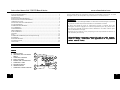
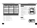
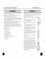
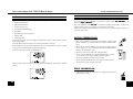
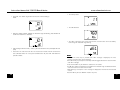
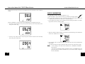
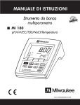
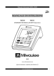
THANK YOU FOR CHOOSING
MARTINI
instruments
Sales and Technical Service Contacts:
Milwaukee Electronics Kft.
Alsókikötő sor 11.
6726, Szeged, Hungary
Tel: +36-62-428-050
Fax: +36-62-428-051
e-mail: [email protected]
Milwaukee Instruments, Inc.
2950 Business Park Drive Rocky Mount, NC
27804 USA
Tel: +1 252 443 3630
Fax: +1 252 443 1937
e-mail: [email protected]
www.milwaukeeinst.com
www.milwaukeeinst.com
MANMI190R1
10/05
Instruction Manual Mi 190 DO Bench Meter
www.milwaukeeinst.com
FUNCTIONAL DESCRIPTION ...................................................................................... .2
GENERAL DESCRIPTION ............................................................................................ .4
SPECIFICATIONS ....................................................................................................... .5
PROBE FUNCTIONAL DESCRIPTION...................................................................................................6
PROBE CONNECTION AND PREPARATION.......................................................................................7
OPERATIONAL GUIDE ................................................................................................ 8
SALINITY AND ALTITUDE COMPENSATION.........................................................................................9
D.O. MEASUREMENTS............................................................................................................................9
TEMPERATURE MEASUREMENTS..........................................................................................................10
D.O. CALIBRATION...............................................................................................................................11
INITIAL PREPARATION...........................................................................................................................11
ZERO CALIBRATION.............................................................................................................................11
SLOPE CALIBRATION............................................................................................................................13
LOGGING.............................................................................................................................................14
SETUP.......................................................................................................................................................18
TEMPERATURE CALIBRATION (for technical personnel only)...............................................................22
PC INTERFACE.......................................................................................................................................23
PROBE MAINTENANCE........................................................................................................................25
TROUBLESHOOTING...........................................................................................................................26
ACCESSORIES.......................................................................................................................................26
For your Safety don’t use or store the instrument in hazardous environments. To avoid
damages or burns, do not perform any measurement in microwave ovens.
WARRANTY
This instrument is warranted against defects in materials and manufacturing for a period of
3 years from the date of purchase. Electrodes are warranted for 6 months.
If during this period the repair or replacement of parts is required, where the
damage is not due to negligence or erroneous operation by the user, please return
the intrument, electrode and probe to either distributor or our office and the repair
will be effected free of charge.
Damage due to accidents, misuse, tampering or lack of prescribed maintenance is
not covered by the warranty.
Milwaukee/Martini instruments reserves the right to make improvements in design, construction and appearance of its products
without advance notice.
FUNCTIONAL DESCRIPTION
DISPLAY
A. PRIMARY DISPLAY
B. MEASURING UNIT FOR PRIMARY
DISPLAY
C. CALIBRATION MESSAGES
D. SETUP, LOG MODE
E.
REQUIRE USER CONFIRMATION
F.
CALIBRATION MODE
G. SECONDARY DISPLAY
H. TEMPERATURE UNIT
I.
2
CALIBRATION WRONG MESSAGE
A
B
I
C
H
D
E
k
G
F
27
Instruction Manual Mi 190 DO Bench Meter
www.milwaukeeinst.com
FUNCTIONAL DESCRIPTION
TROUBLESHOOTING
SYMPTOMS
PROBLEM
SOLUTION
FRONT PANEL
1. Liquid Crystal Display (LCD)
Reading fluctuates up and
down (noise).
DO probe not properly
connected.
Insert the probe.
Display shows DO reading
blinking.
Reading out of range.
Recalibrate the meter;
Check the sample is within
measurable range;
3. MR key, to enter/exit recall mode
4. ACCEPT key, to confirm value
Meter fails to calibrate or
gives faulty readings.
Broken DO probe.
Replace the probe.
At startup the meter displays
all LCD tags permanently
One of the keys is blocked.
Check the keyboard or
contact your dealer.
6. SETUP key, to enter/exit setup mode or
to toggle between delete one and all
logged data
"Err xx" message displayed at Internal error.
start up.
ACCESSORIES
2. CAL key, to enter/exit calibration mode
Contact your dealer or any
Martini Instruments Service
Center.
5. LOG key, to store reading in memory
7.
key, to select SETUP item or to decrease parameter value
8. RANGE key, to select measurement unit/
switch focused data
9.
key, to select SETUP item or to
increase parameter value
MARTINI
instruments
1
11
2
10
3
9
4
8
7
5
6
10. ON/OFF key, to turn the meter ON
and OFF
MA 9070
Zero Oxygen Solution, 230 ml
MA 9071
Refilling Electrolyte Solution, 30 ml
MA 9311
115VAC to 12VDC converter
MA 9310
230VAC to 12VDC converter
MA 840/2
Spare probe with 2 meters (6.7') cable
MA 840/10
Spare probe with 10 meters (33') cable
MA 840/20
Spare probe with 20 meters (67') cable
15. Power supply socket
MA 841
5 spare membranes
16. DIN connector for probe
MA 5200
Windows® compatible software application
13
MA 9350
9-pin PC connection cable
14
11. Secondary LCD
12. Primary LCD
REAR PANEL
13. USB connector
14. RS232 connector
15
26
12
USB
RS232
16
Power
12Vdc
3
Instruction Manual Mi 190 DO Bench Meter
<ETX> is 03 ASCII code character (end of text)
<answer>:
<ACK> is sent for a recognized command
<CAN> is sent when the instrument is logging
<Err6>/<Err8> is sent when the command is incorrect or the instrument is not in
measurement mode.
COMMANDS REQUIRING AN ANSWER
The instrument will answer for these commands with:
<STX> <answer> <checksum> <ETX>
where the checksum is the bytes sum of the answer string sent as 2 ASCII characters.
All the answer messages are with ASCII characters.
RDO
Causes the instrument to send a complete set of readings in according with the DO range.
MDL
Requests the instrument model name and firmware code (16 ASCII chars).
INF
Requests the setup parameters.
SAM
Requests the number of logged samples (4 chars).
LDDO xxx Requests the xxxth DO record logged data.
L A D O Requests all DO Log on demand.
Notes:
•“Err8” is sent if the instrument is not in measurement mode.
•“Err6” is sent if the requested range is not available.
•“Err4” is sent if the requested set parameter is not available.
•“Err3” is sent if the Log on demand is empty.
•Invalid commands will be ignored.
www.milwaukeeinst.com
SPECIFICATIONS
Range
DO
Resolution
Temp
DO
Accuracy
(@ 20 °C / 68 °F)
Calibration
Altitude Compensation
Resolution
Salinity Compensation
Resolution
Temperature
Compensation
Probe
Computer Interface
Power supply
Dimensions
Weight
Environment
Warranty
Temp
DO
0.00 to 45.00 ppm O2
0.0 to 300.0 % O2
-5.0 to 55.0 °C (23.0 to 131.0 °F)
0.01 ppm
0.1 %
0.1 °C (0.1 °F)
±1.5 % of full scale
Temp ±0.4 °C (±0.8 °F)
DO
single or double point at 0% (MI 9070) and 100% (in air)
Temp 2-point, at 0 and 50 °C (32.0 and 122.0 °F)
0 to 4 000 m (13 120’)
100 m (328’)
0 to 40 g/l
1 g/l
Automatic, from 0.0 to 50.0 °C (32.0 to 122.0 °F)
MA 840/2
RS232/USB opto-isolated
12 VDC power adapter
230 x 160 x 95 mm (9.0 x 6.3 x 3.7")
0.9 kg (2.0 lb.)
0 to 50 °C (32 to 122 °F) ; max RH 95%
3 years
This instrument is in compliance with CE Directives.
24
5
Instruction Manual Mi 190 DO Bench Meter
TEMPERATURE CALIBRATION (for technical personnel only)
www.milwaukeeinst.com
PROBE CONNECTION AND PREPARATION
The Mi 190 is factory calibrated for temperature.
Martini’s DO probes are interchangeable and no temperature calibration is needed when they
are replaced.
If the temperature measurements are inaccurate, temperature recalibration should be performed.
For an accurate recalibration, contact your dealer or the nearest Martini Customer Service Center,
or follow the instructions bellow.
• Prepare a vessel containing ice and water and another one containing hot water (at a
temperature of around 50 °C). Place insulation material around the vessels to minimize
temperature changes.
• Use a calibrated thermometer with a resolution of 0.1 °C as a reference thermometer.
To take measurements, connect the D.O. probe to the meter securely by aligning the
pins with the socket located on the back of the meter, pushing the plug in and tightening
the threaded ring.
Probes shipped from Martini Instruments are dry. To hydrate the probe and prepare it
for use, connect it to the meter and proceed as follows:
Shipping
• With the instrument off, press and hold down the LOG & MR keys, then power on the
instrument. The “CALIBRATION” tag will appear and the secondary LCD will show 0.0 °C.
2. Wet the sensor by soaking the bottom 2½ cm (1") of
the probe in electrolyte (MA 9071) for 5 minutes.
black
• Immerse the temperature probe in the vessel with ice and water as near as possible to the
reference thermometer. Allow a few seconds for the probe to stabilize.
3. Rinse the membrane cap (MA 841 supplied in the kit
with the meter) with electrolyte solution while shaking it
gently. Refill with clean electrolyte solution.
red
• Use the UP and DOWN arrow keys to set the reading on the secondary LCD to that of ice
and water, measured by the reference thermometer. When the reading is stable and close to
the selected calibration point, the “READY” and “ACCEPT” tags will blink.
• Press the ACCEPT key to accept the calibration point. The secondary LCD will show 50.0 °C.
• Immerse the temperature probe in the second vessel as near as possible to the reference
thermometer. Allow a few seconds for the probe to stabilize.
• Use the UP and DOWN arrow keys to set the reading on the secondary LCD to that of the
hot water, measured by the reference thermometer.
• When the reading is stable and close to the selected calibration point, the “READY” and
“ACCEPT” tags will blink.
• Press the ACCEPT key to accept the calibration point. The instrument returns to measurement
mode.
Note: If the reading is not close to the selected calibration point, “WRONG” tag will blink. Change
Note
the temperature probe and restart calibration.
22
cap
1. Remove the red and black plastic cap. This cap is for
shipping purposes and can be thrown away.
4. Tap gently the sides of the membrane cap with your
finger tip to ensure that no air bubbles are trapped. To
avoid damaging the membrane, do not tap it directly on
the bottom.
5. Make sure that the rubber O-ring sits properly inside
the membrane cap.
6. With the sensor facing down, slowly screw the cap
clockwise. Some electrolyte will overflow.
When not in use and during polarization (see page 8), use
the protective transparent cap supplied in the kit with the
meter.
FILL FIRST
THEN TAP
THEN SCREW
BACK ON
7
Instruction Manual Mi 190 DO Bench Meter
OPERATIONAL GUIDE
www.milwaukeeinst.com
A lt it u d e , M e t e r s a b o v e S e a L e v e l
ºC
0 m
INITIAL PREPARATION
Plug the 12 VDC adapter into the power supply socket.
Connect the DO probe to the 7-pin connector. Make sure the probe sleeve is properly
inserted and tighten the threaded ring.
Turn the instrument on by pressing ON/OFF. All LCD tags are displayed and a beep is heard
while the instrument performs a self test.
• After a few seconds “Cond” message appears on the LCD to inform the user that the probe
is in auto-conditioning (automatic polarization) mode.
600
m
900 1200 15001800 2100 2400 2700 3000 3300 3600 3900 4000
m
m
m
m
m
m
m
m
m
m
m
m
0
1 4 .6 1 4 .1 1 3 .6 1 3 .1 1 2 .6
1 2 .1 1 1 .7 1 1 .2
1 0 .8
1 0 .4
2
4
1 3 .8 1 3 .3 1 2 .8 1 2 .4 1 1 .9
1 1 .5 1 1 .0 1 0 .6
1 0 .2
1 3 .1 1 2 .6 1 2 .2 1 1 .7 1 1 .3
1 0 .9 1 0 .5
1 0 .1
9 .7
6
1 2 .4 1 2 .0 1 1 .5 1 1 .1 1 0 .7
1 0 .3
9 .9
9 .6
8
1 1 .8 1 1 .4 1 1 .0 1 0 .6 1 0 .2
9 .8
9 .5
9 .1
10
1 1 .3 1 0 .9 1 0 .5 1 0 .1
9 .7
9 .4
9 .0
12
1 0 .8 1 0 .4 1 0 .0
9 .6
9 .3
8 .9
14
1 0 .3
9 .9
9 .6
9 .2
8 .9
8 .5
16
9 .9
9 .5
9 .2
8 .8
8 .5
8 .2
7 .9
7 .6
18
9 .5
9 .1
8 .8
8 .5
8 .1
7 .8
7 .6
7 .3
ºF
1 0 .0
9 .7
9 .3
9 .0
8 .9
3 2 .0
9 .9
9 .5
9 .2
9 .3
9 .0
8 .7
8 .8
8 .5
8 .4
3 5 .6
8 .4
8 .0
7 .9
3 9 .2
9 .2
8 .9
8 .6
8 .8
8 .4
8 .1
8 .2
7 .9
7 .6
7 .5
4 2 .8
7 .8
7 .5
7 .3
7 .2
4 6 .4
8 .7
8 .4
8 .1
7 .8
7 .5
7 .2
6 .9
6 .8
5 0 .0
8 .6
8 .3
8 .0
7 .7
8 .2
7 .9
7 .6
7 .4
7 .4
7 .1
6 .9
6 .6
6 .5
5 3 .6
7 .1
6 .8
6 .6
6 .3
6 .2
5 7 .2
7 .3
7 .0
6 .8
6 .5
6 .3
6 .1
6 .0
6 0 .8
7 .0
6 .8
6 .5
6 .3
6 .0
5 .8
5 .7
6 4 .4
20
9 .1
8 .8
8 .4
8 .1
7 .8
7 .5
7 .3
7 .0
6 .7
6 .5
6 .2
6 .0
5 .8
5 .6
5 .5
6 8 .0
• When this message disappears, the probe is polarized and the instrument can be calibrated.
22
8 .7
8 .4
8 .1
7 .8
7 .5
7 .2
7 .0
6 .7
6 .5
6 .2
6 .0
5 .8
5 .6
5 .4
5 .3
7 1 .6
• If the probe is disconnected, the meter will display “----”.
24
8 .4
8 .1
7 .8
7 .5
7 .2
7 .0
6 .7
6 .5
6 .2
6 .0
5 .8
5 .6
5 .4
5 .2
5 .1
7 5 .2
PROBE POLARIZATION
The probe is under polarization with a fixed voltage of approximately 800 mV.
Probe polarization is essential for stable measurements with the same recurring degree of accuracy.
With the probe properly polarized, oxygen is continually consumed when it passes through the
sensitive diaphragm and dissolves in the electrolyte solution contained in the probe.
If polarization is interrupted, the electrolyte solution continues to be enriched with oxygen until
it reaches an equilibrium with the surrounding solution.
Whenever measurements are taken with a non-polarized probe, the oxygen level revealed is
both that of the tested solution, as well as that present in the electrolyte solution. This reading is
incorrect.
The calibration of this instrument is very simple.
8
300
m
25
8 .3
8 .0
7 .7
7 .4
7 .1
6 .8
6 .6
6 .4
6 .1
5 .9
5 .7
5 .5
5 .3
5 .1
5 .0
7 7 .0
26
8 .1
7 .8
7 .5
7 .2
7 .0
6 .7
6 .5
6 .2
6 .0
5 .8
5 .6
5 .4
5 .2
5 .0
4 .9
7 8 .8
28
7 .8
7 .5
7 .3
7 .0
6 .7
6 .5
6 .2
6 .0
5 .8
5 .6
5 .4
5 .2
5 .0
4 .8
4 .7
8 2 .4
30
7 .6
7 .3
7 .0
6 .8
6 .5
6 .3
6 .0
5 .8
5 .6
5 .4
5 .2
5 .0
4 .8
4 .6
4 .6
8 6 .0
32
7 .3
7 .0
6 .8
6 .5
6 .3
6 .1
5 .8
5 .6
5 .4
5 .2
5 .0
4 .8
4 .7
4 .5
4 .4
8 9 .6
34
7 .1
6 .8
6 .6
6 .3
6 .1
5 .9
5 .6
5 .4
5 .2
5 .0
4 .9
4 .7
4 .5
4 .3
4 .3
9 3 .2
36
6 .8
6 .6
6 .3
6 .1
5 .9
5 .7
5 .5
5 .3
5 .1
4 .9
4 .7
4 .5
4 .4
4 .2
4 .1
9 6 .8
38
6 .6
6 .4
6 .1
5 .9
5 .7
5 .5
5 .3
5 .1
4 .9
4 .7
4 .5
4 .4
4 .2
4 .1
4 .0
1 0 0 .4
40
6 .4
6 .2
5 .9
5 .7
5 .5
5 .3
5 .1
4 .9
4 .7
4 .6
4 .4
4 .2
4 .1
3 .9
3 .9
1 0 4 .4
42
6 .2
6 .0
5 .8
5 .6
5 .3
5 .2
5 .0
4 .8
4 .6
4 .4
4 .3
4 .1
4 .0
3 .8
3 .8
1 0 7 .6
44
6 .0
5 .8
5 .6
5 .4
5 .2
5 .0
4 .8
4 .6
4 .5
4 .3
4 .1
4 .0
3 .8
3 .7
3 .7
1 1 1 .2
46
5 .8
5 .6
5 .4
5 .2
5 .0
4 .8
4 .7
4 .5
4 .3
4 .2
4 .0
3 .9
3 .7
3 .6
3 .5
1 1 4 .8
48
5 .7
5 .5
5 .3
5 .1
4 .9
4 .7
4 .5
4 .4
4 .2
4 .0
3 .9
3 .7
3 .6
3 .5
3 .4
1 1 8 .4
50
5 .5
5 .3
5 .1
4 .9
4 .7
4 .6
4 .4
4 .2
4 .1
3 .9
3 .8
3 .6
3 .5
3 .4
3 .3
1 2 2 .0
21
Instruction Manual Mi 190 DO Bench Meter
www.milwaukeeinst.com
The salinity affects the D.O. concentration, decreasing its value. The table below shows the
maximum oxygen solubility at various temperatures and salinity levels.
º C
S a lin ity
(g / l) a t
S e a
L e v e l
º F
0 g /l
1 0 g /l
2 0 g /l
3 0 g /l
3 5 g /l
0
1 4 .6 0
1 3 .6 4
1 2 .7 4
1 1 .9 0
1 1 .5 0
2
1 3 .8 1
1 2 .9 1
1 2 .0 7
1 1 .2 9
1 0 .9 1
3 6 .5
4
1 3 .0 9
1 2 .2 5
1 1 .4 7
1 0 .7 3
1 0 .3 8
3 9 .2
6
1 2 .4 4
1 1 .6 5
1 0 .9 1
1 0 .2 2
9 .8 9
4 2 .8
8
1 1 .8 3
1 1 .0 9
1 0 .4 0
9 .7 5
9 .4 4
4 6 .4
10
1 1 .2 8
1 0 .5 8
9 .9 3
9 .3 2
9 .0 3
5 0 .0
12
1 0 .7 7
1 0 .1 1
9 .5 0
8 .9 2
8 .6 5
5 3 .6
14
1 0 .2 9
9 .6 8
9 .1 0
8 .5 5
8 .3 0
5 7 .2
16
9 .8 6
9 .2 8
8 .7 3
8 .2 1
7 .9 7
6 0 .8
3 2 .0
18
9 .4 5
8 .9 0
8 .3 9
7 .9 0
7 .6 6
6 4 .4
20
9 .0 8
8 .5 6
8 .0 7
7 .6 0
7 .3 8
6 8 .0
22
8 .7 3
8 .2 3
7 .7 7
7 .3 3
7 .1 2
7 1 .6
24
8 .4 0
7 .9 3
7 .4 9
7 .0 7
6 .8 7
7 5 .2
25
8 .2 4
7 .7 9
7 .3 6
6 .9 5
6 .7 5
7 7 .0
26
8 .0 9
7 .6 5
7 .2 3
6 .8 3
6 .6 4
7 8 .8
28
7 .8 1
7 .3 8
6 .9 8
6 .6 1
6 .4 2
8 2 .4
30
7 .5 4
7 .1 4
6 .7 5
6 .3 9
6 .2 2
8 6 .0
32
7 .2 9
6 .9 0
6 .5 4
6 .1 9
6 .0 3
8 9 .6
34
7 .0 5
6 .6 8
6 .3 3
6 .0 1
5 .8 5
9 3 .2
36
6 .8 2
6 .4 7
6 .1 4
5 .8 3
5 .6 8
9 6 .8
38
6 .6 1
6 .2 8
5 .9 6
5 .6 6
5 .5 1
1 0 0 .4
40
6 .4 1
6 .0 9
5 .7 9
5 .5 0
5 .3 6
1 0 4 .0
42
6 .2 2
5 .9 3
5 .6 3
5 .3 5
5 .2 2
1 0 7 .6
44
6 .0 4
5 .7 7
5 .4 8
5 .2 1
5 .0 9
1 1 1 .2
46
5 .8 7
5 .6 1
5 .3 3
5 .0 7
4 .9 7
1 1 4 .8
48
5 .7 0
5 .4 7
5 .2 0
4 .9 5
4 .8 5
1 1 8 .4
50
5 .5 4
5 .3 3
5 .0 7
4 .8 3
4 .7 5
1 2 2 .0
Before proceeding with the calibration, make sure the probe is ready for measurements (see page 7),
i.e. the membrane cap is filled with electrolyte and the probe is connected to the meter and properly
polarized.
For an accurate calibration, it is recommended to wait at least 15 minutes to ensure precise
conditioning of the probe.
Keep the protective cap on during polarization time and remove it for calibration and measurements.
Follow the calibration procedure (see page 10).
SALINITY AND ALTITUDE COMPENSATION
If the sample contains significant concentration of salinity or if you are performing measurements at an altitude different from sea level, the read out values must be corrected, taking into
account the lower degree of oxygen solubility in these situations (see pages 20-21).
Remember to set the altitude and/or the salinity before taking any D.O. measurements. The
meter will automatically compensate for these factors.
D.O. MEASUREMENTS
Make sure that the instrument has been calibrated and the protective cap has
been removed.
• Immerse the tip of the probe in the sample to be tested. Allow approximately
one minute for the reading to stabilize.
• The Dissolved Oxygen value (in %) is displayed on the primary LCD and the temperature on
the secondary LCD.
Note
Note:The relationship between salinity and chlorinity for sea water is given by the equation
below:
Salinity (g/l) = 1.80655 Chlorinity (g/l)
20
9
Instruction Manual Mi 190 DO Bench Meter
• Press RANGE to change the reading from % to ppm and vice-versa.
For accurate Dissolved Oxygen measurements, a water movement of 0.3 m/s is required.
This is to ensure that the oxygen-depleted membrane surface is constantly replenished. A
moving stream will provide adequate circulation.
The use of a magnetic stirrer to ensure a certain fluid velocity is recommended.
www.milwaukeeinst.com
Press the arrow keys to change the displayed value.
Press the ACCEPT key to accept the value or the CAL key to escape.
Press the arrow keys to select the next/previous parameter.
Press the SETUP key to exit SETUP menu at any time.
The following table lists the SETUP parameters, their valid values range and the factory
settings (default):
Item
SALt
ALt
TIME
DATE
bEEP
bAud
In Id
tEMP
Description
Salinity Factor
Altitude Factor
Time (hh:mm)
Date (MM.DD.YYYY)
Beep Status
Baud Rate
Instrument ID
Temperature Unit
Valid values
0 to 40 g/l
0 to 4000 m step100 m
00:00 to 23:59
01.01.2000-12.31.2099
ON/OFF
600; 1200; 2400; 4800;9600
0000 to 9999
°C or °F
Default
0
0
00:00
01.01.2005
OFF
2400
0000
°C
TEMPERATURE MEASUREMENTS
The probe has a built-in temperature sensor.
The measured temperature is indicated on the secondary LCD as shown above.
Allow the probe to reach thermal equilibrium before taking any measurement. This can
take several minutes. The greater the difference between the temperature at which the
probe was stored and the temperature of the sample, the longer the time will be.
Note: If “----” is displayed, the D.O. probe is not properly connected or the temperature
is out of range. This also indicates the posibility of a broken probe cable.
10
19
Instruction Manual Mi 190 DO Bench Meter
SETUP
Setup mode allows viewing and modifying the following parameters:
• Salinity Compensation
• Altitude Compensation
• Current Time (hh:mm)
• Current Date (MM.DD.YYYY)
• Beep Status
www.milwaukeeinst.com
D.O. CALIBRATION
Calibrate the instrument frequently, especially if high accuracy is required.
zero calibration
The instrument can be calibrated in maximum 2 points: 0.0% (zero
calibration) and
slope calibration
100.0% (slope
calibration).
The zero calibration of the Mi 190 is very stable, therefore this procedure needs to be
performed only whenever the probe or the membrane is replaced.
However, because the slope calibration is more critical, it is recommended to perform this
procedure every week.
• Baud Rate (serial communication)
• Instrument ID
Select the desired setup parameter using the UP and DOWN arrow keys.
Press the CAL key if you want to change the item value. The selected item (e.g. hour, in setting
up the correct time) and “ACCEPT” tag will start blinking.
Press the arrow keys to change the displayed value.
07
0
INITIAL PREPARATION
MI9
• Temperature Unit
To enter SETUP mode, press and hold the SETUP key for about 1 second while in normal
measurement mode.
• Pour small quantities of MA 9070 Zero Oxygen solution into a
beaker. If possible, use a plastic beaker to minimize any EMC interferences.
MI9070
• Make sure the probe is ready for measurements (see probe preparation on page 7), i.e. the membrane is filled with electrolyte and the
probe is connected to the meter.
• Switch the meter on by pressing the ON/OFF switch.
• For an accurate calibration, it is recommended to wait for at least
15 minutes to ensure precise conditioning of the probe.
• Remove the protective cap from the D.O. probe.
• Set the appropriate altitude factor (see page 21). Make sure the
salinity factor is set to zero (see page 20).
If there is another item to be set (e.g. minutes), press the RANGE key. The other item will start
blinking.
ZERO CALIBRATION
• Submerge the probe into MA 9070 zero oxygen solution and stir
gently for 2-3 minutes.
18
11
Instruction Manual Mi 190 DO Bench Meter
www.milwaukeeinst.com
• The salinity factor
• Press CAL. The “WAIT” tag will blink on the LCD until the reading is
stable.
• The altitude factor
• When the reading is stable, “READY” & “ACCEPT” tags start blinking. Press ACCEPT to
confirm the “0.0%” D.O. calibration.
• The “dEL” message on the primary LCD and the record number on the secondary
LCD along with “ACCEPT” tag blinking.
• If the reading is within the limits (±15% f.s.), the meter stores the value (and adjusts the zero
point).
• Press CAL. The instrument will return to measurement mode and will memorize the
zero calibration data. For a two-point calibration do not press CAL and follow the
procedure below.
Notes:
•If one of the arrow keys is pressed while “dEL” message is displayed, the next/
previous record number will be selected.
•If the SETUP key is pressed, the secondary LCD will toggle between the record number
and “ALL” message.
•Press the ACCEPT key to delete the selected or all records.
•If “dEL ALL” option was selected, all records for the selected range are deleted and the
instrument returns to measurement mode.
•After deleting a record, the “nuLL” message is displayed on the LCD for the selected
record.
Press the MR key to leave RECALL mode at any time.
12
17
Instruction Manual Mi 190 DO Bench Meter
www.milwaukeeinst.com
Pressing the arrow keys, the instrument will display the same parameter but for a different
record:
SLOPE CALIBRATION
It is suggested to perform the slope calibration in air.
• Rinse the probe in clean water to remove any residual zero oxygen solution.
Note: If you did not perform the zero calibration procedure, press CAL and then the
ARROW keys to select the 100% D. O. calibration point.
Press the RANGE key and the instrument will display the next logged parameter:
• The date: month and day on the primary LCD and the year on the secondary LCD,
along with “DATE” tag.
• Dry the probe tip and allow a few seconds for the LCD reading to stabilize. The “WAIT”
tag will blink until the reading is stable.
• When the reading is stable, “READY” & “ACCEPT” tags start blinking. Press ACCEPT to
confirm the “100.0%” D.O. calibration.
• The time: hour and minutes on the primary LCD and the seconds on the secondary
LCD, along with “TIME” tag.
• If the reading is within the limits (±15% f.s.), the meter stores the value (and adjusts the
slope point).
• The instrument stores the slope calibration data and returns to measurement mode.
Note:
• If the reading is not close to the selected value, “WRONG“ & “BUFFER”
tags will blink.
• MI 190 has automatic buffer recognition function. If the ARROW keys are
pressed to select the desired calibration value, the automatic buffer recognition
function is disabled.
16
13
Instruction Manual Mi 190 DO Bench Meter
LOGGING
Up to 50 LOG samples can be stored into memory
LOGGING THE CURRENT DATA
www.milwaukeeinst.com
If the log space is full, “FULL LOC” message will be displayed and no more data will be saved.
When the LOG key is pressed while in measurement mode, a complete set of information is stored.
To store the current reading into memory press the LOG key while in measurement
mode.
The instrument will display the current date (MM.DD) on the primary LCD and the
record number on the secondary LCD, along with “LOG” tag (see example below:
record No. 25, dated June 29).
VIEW LOGGED DATA
Press the MR key to retrieve the information stored while in measurement mode.
If no data were logged, the instrument displays “no rEC” message for the selected range.
The instrument displays then the amount of free log space for about one second and
returns to normal measurement mode (e.g. 18 records free).
Otherwise, the instrument will display the DO value on the primary LCD and the temperature on the secondary LCD, along with last stored record number and “LOG” tag.
If there are less than 6 memory locations remaining, the record number and “Lo” message
will blink to alert the user.
14
15