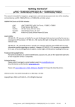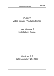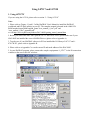
1
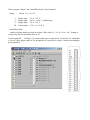
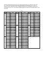
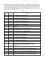
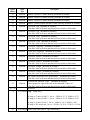
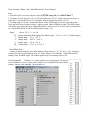
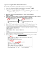
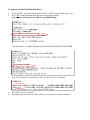
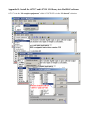
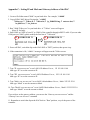
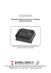
Using I-87117 and I-87118 1. Using i-87117W If you are using the i-87118, please refer to section 2 - “Using i-87118” Note: 1. Please refer to Chapter 1.1 and 1.2 of the ISaGRAF User's Manual to install the ISaGRAF wrokbench and ICP DAS utilities in your PC. The complete manual is burned in the i-8000 CDROM:\napdos\isagraf\8000\english_manu\”user_manual_i_8xx7.pdf” and “user_manual_i_8xx7_appendix.pdf” or visit http://www.icpdas.com/products/PAC/i-8000/getting_started_manual.htm 2. Before you can use the iPAC-8803 plus the i-87117 and i-87017W-E5, please make sure if your iPAC-8803 has installed the correct ISaGRAF driver. (please refer to Appendix A) 3. To make sure if your ISaGRAF software in PC has installed the I/O library of i-87117 and i87017W-E5 , please refer to Appendix B. 4. Please refer to to Appendix C to set the correct IP and mask address of the iPAC-8803. 5. In your ISaGRAF program, please connect the complex equipmenet “i_87117” in the IO connection windows to the correct slot No. as below. Then set proper “Range” and “NumOfWavePoint” in each channel. Range : Can be 5, 8, 9 or 1D 5 : Voltage input , -2.5 to +2.5 V 8 : Voltage input , -10.0 to +10.0 V (default rage) 9 : Voltage input , -5.0 to +5.0 V 1D : Current input , -31.25 to +31.25 A NumOfWavePoint : number of points inside one single waveform. Value can be 10 , 20 , 40 , 60 or 100 . Setting as wrong value will use the default value of 20 . ZeroCrossingChk : Default is 1, it means eanble zero crossing check. If setting it as 0 will disable it. (For AC input, please enable it. For straight line DC input, that is voltage / current is not changing , please disable it) There are 8 analog channels in the i-87117 . Please plug them in the slot 0 through 7 of the iPAC8803. The i-87117 can not be used in the RS-485 remote I/O expansion base .The HMI like InduSoft can Read / Write iPAC-8803 via Modbus RTU protocol or via Modbus TCP/IP protocol. Each channel in the i-87117 has a absolute Modbus address area which has 500 Modbus number in the iPAC-8803. Table 1 Slot Channel 0 1 2 Address Slot Channel Address Slot Channel Address 1 20001 - 20500 1 32001 - 32500 1 44001 - 44500 2 20501 - 21000 2 32501 - 33000 2 44501 - 45000 3 21001 - 21500 3 33001 - 33500 3 45001 - 45500 4 21501 - 22000 4 33501 - 34000 4 45501 - 46000 5 22001 - 22500 5 34001 - 34500 5 46001 - 46500 6 22501 - 23000 6 34501 - 35000 6 46501 - 47000 7 23001 - 23500 7 35001 - 35500 7 47001 - 47500 8 23501 - 24000 8 35501 - 36000 8 47501 - 48000 1 24001 - 24500 1 36001 - 36500 1 48001 - 48500 2 24501 - 25000 2 36501 - 37000 2 48501 - 49000 3 25001 - 25500 3 37001 - 37500 3 49001 - 49500 4 25501 - 26000 4 37501 - 38000 4 49501 - 50000 5 26001 - 26500 5 38001 - 38500 5 50001 - 50500 6 26501 - 27000 6 38501 - 39000 6 50501 - 51000 7 27001 - 27500 7 39001 - 39500 7 51001 - 51500 8 27501 - 28000 8 39501 - 40000 8 51501 - 52000 1 28001 - 28500 1 40001 - 40500 2 28501 - 29000 2 40501 - 41000 3 29001 - 29500 3 41001 - 41500 4 29501 - 30000 4 41501 - 42000 5 30001 - 30500 5 42001 - 42500 6 30501 - 31000 6 42501 - 43000 7 31001 - 31500 7 43001 - 43500 8 31501 - 32000 8 43501 - 44000 3 4 5 6 7 The detailed definition of the Modbus number in the i-87117 's channel area is listed as Table 2. The address in Table 2 is the Offset address. The offset address 1 is mapped to the starting address 1 in the Table1. So the absolute modbus address is the “Offset Address in Table2” plus the “Starting Address of the associated channel in Table 1” minus 1 . That is abs_addr = offset_addr + start_addr – 1 . For example, The absolute Modbus address of the channel 2 's offset 1 of the i-87117 in slot 1 is 24501, its offset 101 has absolute address as 24601 . Table 2 Offset Address Data Type 1 Boolean Low alarm status of Vpp (Read only) 2 Boolean High alarm status of Vpp (Read only) 3 Boolean Low alarm status of Vrms (Read only) 4 Boolean High alarm status of Vrms (Read only) 5 Boolean Low alarm status of frequency (Read only) 6 Boolean High alarm status of frequency (Read only) 7 Boolean Low alarm status of SINAD (Read only) 8 Description Reserved 9 Boolean Low alarm status of min. voltage (Read only) 10 Boolean High alarm status of min. volatge (Read only) 11 Boolean Low alarm status of max. voltage (Read only) 12 Boolean High alarm status of max. voltage (Read only) 13 Boolean Low alarm status of TT (Read only) 14 Boolean High alarm status of TT (Read only) 15 Boolean Low alarm status of TH (Read only) 16 Boolean High alarm status of TH (Read only) 17 Boolean Low alarm status of TL (Read only) 18 Boolean High alarm status of TL (Read only) 19 Boolean High alarm status of Pattern difference (Read only) 20 Boolean Return True if any alarm status of item 1 thru. 19 is True. Return False if all alarm status of item 1 thru. 19 are False. (Read only) 21 Boolean Enable / Disable Vpp alarm checking (Readable & writable) 22 Boolean Enable / Disable Vrms alarm checking (Readable & writable) 23 Boolean Enable / Disable Frequency alarm checking (Readable & writable) 24 Boolean Enable / Disable SINAD alarm checking (Readable & writable) 25 Boolean Enable / Disable Vmin alarm checking (Readable & writable) 26 Boolean Enable / Disable Vmax alarm checking (Readable & writable) Offset Address Data Type 27 Boolean Enable / Disable TT alarm checking (Readable & writable) 28 Boolean Enable / Disable TH alarm checking (Readable & writable) 29 Boolean Enable / Disable TL alarm checking (Readable & writable) 30 Boolean Enable / Disable Pattern difference alarm checking (Readable & writable) 31 Boolean Clear min. Vpp (Readable & writable) (The iPAC-8803 will run it and then will reset it back to False auto.) 32 Boolean Clear max. Vpp (Readable & writable) (The iPAC-8803 will run it and then will reset it back to False auto.) 33 Boolean Clear min. Vrms (Readable & writable) (The iPAC-8803 will run it and then will reset it back to False auto.) 34 Boolean Clear max. Vrms (Readable & writable) (The iPAC-8803 will run it and then will reset it back to False auto.) 35 Boolean Clear min. Frequency (Readable & writable) (The iPAC-8803 will run it and then will reset it back to False auto.) 36 Boolean Clear max. Frequency (Readable & writable) (The iPAC-8803 will run it and then will reset it back to False auto.) 37 Boolean Clear min. SINAD (Readable & writable) (The iPAC-8803 will run it and then will reset it back to False auto.) 38 Boolean Clear max. SINAD (Readable & writable) (The iPAC-8803 will run it and then will reset it back to False auto.) 39 Boolean Clear min. voltage (Readable & writable) (The iPAC-8803 will run it and then will reset it back to False auto.) 40 Boolean Clear max. voltage (Readable & writable) (The iPAC-8803 will run it and then will reset it back to False auto.) 41 Boolean Set current WaveForm as the good pattern. (Readable & writable) (The iPAC-8803 will run it and then will reset it back to False auto.) 42 43 – 50 51 Boolean Description Clear all min. and max. value. (Readable & writable) This command is equal to the sum of the command 31 thru. 40. (The iPAC-8803 will run it and then will reset it back to False auto.) Reserved 32-bit Integer Vpp. (Read only) If range is 5, unit is 0.0001 V , for ex., -25000 is -2.5 V, 25000 is +2.5V If range is 9, unit is 0.0001 V , for ex., -50000 is -5.0 V, 50000 is +5.0V If range is 8, unit is 0.001 V , for ex., -10000 is -10 V, 10000 is +10V If range is 1D, unit is mA , for ex., -31250 is -31.25 A , 31250 is +31.25A 53 32-bit Integer Vrms (unit is the same as Vpp) (Read only) Offset Address Data Type Description 55 32-bit Integer Frequency, unit is 0.01Hz. For ex, 5000 is 50Hz , 950000 is 9500Hz (Read only) 57 32-bit Integer SINAD, unit is 0.01 (Read only) 59 32-bit Integer min Vpp (unit is the same as Vpp) (Read only) 61 32-bit Integer Date where the min Vpp happened. (Read only) For ex, value 20080926 means Sep.26,2008 63 32-bit Integer Time where the min Vpp happened (Read only) For ex, value 130943 means 13:09:43 65 32-bit Integer max Vpp (unit is the same as Vpp) (Read only) 67 32-bit Integer Date where the max Vpp happened. (Format is same as min Vpp date) (Read only) 69 32-bit Integer Time where the max Vpp happened. (Format is same as min Vpp time) (Read only) 71 32-bit Integer min Vrms (unit is the same as Vpp) (Read only) 73 32-bit Integer Date where the min Vrms happened. (Format is same as min Vpp date) (Read only) 75 32-bit Integer Time where the min Vrms happened. (Format is same as min Vpp time) (Read only) 77 32-bit Integer max Vrms (unit is the same as Vpp) (Read only) 79 32-bit Integer Date where the max Vrms happened. (Format is same as min Vpp date) (Read only) 81 32-bit Integer Time where the max Vrms happened. (Format is same as min Vpp time) (Read only) 83 32-bit Integer min Frequency, unit is 0.01Hz (Read only) 85 32-bit Integer Date where the min Frequency happened. (Read only) (Format is same as min Vpp date) 87 32-bit Integer Time where the min Frequency happened. (Read only) (Format is same as min Vpp time) 89 32-bit Integer max Frequency, unit is 0.01Hz (Read only) 91 32-bit Integer Date where the max Frequency happened. (Read only) (Format is same as min Vpp date) 93 32-bit Integer Time where the max Frequency happened. (Read only) (Format is same as min Vpp time) 95 32-bit Integer min SINAD, unit is 0.01 (Read only) 97 32-bit Integer Date where the min SINAD happened. (Format is same as min Vpp date) (Read only) Offset Address Data Type Description 99 32-bit Integer Time where the min SINAD happened. (Format is same as min Vpp time) (Read only) 101 32-bit Integer max SINAD, unit is 0.01 (Read only) 103 32-bit Integer Date where the max SINAD happened. (Format is same as min Vpp date) (Read only) 105 32-bit Integer Time where the max SINAD happened. (Format is same as min Vpp time) (Read only) 107 32-bit Integer Min. voltage (unit is the same as Vpp) (Read only) 109 32-bit Integer Date where the min. voltage happened. (Format is same as min Vpp date) (Read only) 111 32-bit Integer Time where the min. voltage happened. (Format is same as min Vpp time) (Read only) 113 32-bit Integer Max. voltage (unit is the same as Vpp) (Read only) 115 32-bit Integer Date where the max voltage happened. (Format is same as min Vpp date) (Read only) 117 32-bit Integer Time where the max voltage happened. (Format is same as min Vpp time) (Read only) 119 32-bit Integer current min. voltage (unit is the same as Vpp) (Read only) 121 32-bit Integer current max. voltage (unit is the same as Vpp) (Read only) 123 32-bit Integer current TT, unit is 0.00001ms (0.00000001 second) (Read only) 125 32-bit Integer current TH, unit is 0.00001ms (0.00000001 second) (Read only) 127 32-bit Integer current TL, unit is 0.00001ms (0.00000001 second) (Read only) 129 32-bit Integer current Patern difference (unit is the same as Vpp) (Read only) 131 32-bit Integer Date where the Alarm happened. (Read only) For ex, value 20080926 means Sep.26,2008 133 32-bit Integer Time where the Alarm happened. (Read only) For ex, value 071559 means 07:15:59 135 32-bit Integer The sampling number of one WaveForm. (amount of points in one waveform) (Read only) Value is one of 10, 20, 40, 60, 100 (This value is set in the ISaGRAF) 137 – 140 141 Reserved 32-bit Integer Low alarm setting of Vpp (unit is the same as Vpp) (This value can only be positive, not negative) (Readable & writable) Offset Address Data Type Description 143 32-bit Integer High alarm setting of Vpp (unit is the same as Vpp) (This value can only be positive, not negative) (Readable & writable) 145 32-bit Integer Low alarm setting of Vrms (unit is the same as Vpp) (Readable & writable) 147 32-bit Integer High alarm setting of Vrms (unit is the same as Vpp) (Readable & writable) 149 32-bit Integer Low alarm setting of Frequency, unit is 0.01Hz (This value can only be positive, not negative) (Readable & writable) 151 32-bit Integer High alarm setting of Frequency, unit is 0.01Hz (This value can only be positive, not negative) (Readable & writable) 153 32-bit Integer Low alarm setting of SINAD, unit is 0.01 (Readable & writable) 155 Reserved 157 32-bit Integer Low alarm setting of Vmin, (unit is the same as Vpp) (Readable & writable) 159 32-bit Integer High alarm setting of Vmin (unit is the same as Vpp) (Readable & writable) 161 32-bit Integer Low alarm setting of Vmax (unit is the same as Vpp) (Readable & writable) 163 32-bit Integer High alarm setting of Vmax (unit is the same as Vpp) (Readable & writable) 165 32-bit Integer Low alarm setting of TT, unit is 0.00001ms (0.00000001 second) (This value can only be positive, not negative) (Readable & writable) 167 32-bit Integer High alarm setting of TT, unit is 0.00001ms (0.00000001 second) (This value can only be positive, not negative) (Readable & writable) 169 32-bit Integer Low alarm setting of TH, unit is 0.00001ms (0.00000001 second) (This value can only be positive, not negative) (Readable & writable) 171 32-bit Integer High alarm setting of TH, unit is 0.00001ms (0.00000001 second) (This value can only be positive, not negative) (Readable & writable) 173 32-bit Integer Low alarm setting of TL, unit is 0.00001ms (0.00000001 second) (This value can only be positive, not negative) (Readable & writable) 175 32-bit Integer High alarm setting of TL, unit is 0.00001ms (0.00000001 second) (This value can only be positive, not negative) (Readable & writable) 177 32-bit Integer High Alarm setting of Patern difference, unit is mV (0.001 Volt) (This value can only be positive, not negative) (unit is the same as Vpp) (Readable & writable) Offset Address 179 Data Type Description 32-bit Integer The time gap between two sampling points in one WaveForm. unit is 0.001 ms (micro- second) . i-87117 : Value can be 5 to 1000 i-87118 : Value can be 1 to 1000 (This value can only be positive, not negative) (Readable & writable) 181 – 200 Reserved Current WaveForm Point (max. 100 sampling points in one waveform) Each 16-bit Integer contains one sampling points. . 201 – 300 16-bit Integer If “range” = “5”, value -32768 means -2.5 V , +32767 is +2.5 V If “range” = “9”, value -32768 means -5.0 V , +32767 is +5.0 V If “range” = “8”, value -32768 means -10.0 V , +32767 is +10.0 V If “range” = “1D”, value --32768 means -31.25A, +32767 is +31.25A Alarm WaveForm Point (max. 100 sampling points in one waveform) Each 16-bit Integer contains one sampling points. . 301 - 400 16-bit Integer If “range” = “5”, value -32768 means -2.5 V , +32767 is +2.5 V If “range” = “9”, value -32768 means -5.0 V , +32767 is +5.0 V If “range” = “8”, value -32768 means -10.0 V , +32767 is +10.0 V If “range” = “1D”, value --32768 means -31.25A, +32767 is +31.25A WaveForm of the good patern (max. 100 sampling points) Each 16-bit Integer contains one sampling points. . 401 - 500 16-bit Integer If “range” = “5”, value -32768 means -2.5 V , +32767 is +2.5 V If “range” = “9”, value -32768 means -5.0 V , +32767 is +5.0 V If “range” = “8”, value -32768 means -10.0 V , +32767 is +10.0 V If “range” = “1D”, value --32768 means -31.25A, +32767 is +31.25A 2. Using i-87118W If you are using the i-87117, please refer to section 1 - “Using i-87117” Note: 1. Please refer to Chapter 1.1 and 1.2 of the ISaGRAF User's Manual to install the ISaGRAF wrokbench and ICP DAS utilities in your PC. The complete manual is burned in the i-8000 CDROM:\napdos\isagraf\8000\english_manu\”user_manual_i_8xx7.pdf” and “user_manual_i_8xx7_appendix.pdf” or visit http://www.icpdas.com/products/PAC/i-8000/getting_started_manual.htm 2. Before you can use the iPAC-8803 plus the i-87118 and i-87017W-E5, please make sure if your iPAC-8803 has installed the correct ISaGRAF driver. (please refer to Appendix A) 3. To make sure if your ISaGRAF software in PC has installed the I/O library of i-87117, i-87118 and i-87017W-E5 , please refer to Appendix B. 4. Please refer to to Appendix C to set the correct IP and mask address of the iPAC-8803. 5. In your ISaGRAF program, please connect the complex equipmenet “i_87118” in the IO connection windows to the correct slot No. as below. Note: One iPAC-8803 can accept only max. three i-87118 in its Slot 5 thru. 7. Then set proper “Range” and “NumOfWavePoint” in each channel. Note: 1. One iPAC-8803 can accept only max. three i-87118 (range=1E) in its Slot 5 thru. 7. 2. If setting i-87118's range as 5, 8, 9, or 1D, then it becomes i-87117. In this case you can plug it at slot 0 thru. 7 just like the real i-87117 card does. (Please refer the data of the i-87117) 3. If setting range as 1E, the “NumOfWavePoint” of the 56KHz signal is always using 100 points. Time gap between two points is always 1 (micro-second , that is 0.000001 second). The 9KHz signal will use the same time gap but its “NumOfWavePoint” can be set as 20, 40, 60 or 100. (recommend to set “NumOfWavePoint” to 100 for 9KHz signal if range = 1E) Range : Can be 1E , 5 , 8 , 9 or 1D 1E : Voltage input with 9KHz signal plus 56KHz signal , -10.0 to +10.0 V (Default range) 5 : Voltage input , -2.5 to +2.5 V 8 : Voltage input , -10.0 to +10.0 V 9 : Voltage input , -5.0 to +5.0 V 1D : Current input , -31.25 to +31.25 A NumOfWavePoint : number of points inside the waveform diagram. Value can be 10 , 20 , 40 , 60 or 100 . Setting as wrong value will use the default value of 20 . If the “Range” is 1E, then this “NumOfWavePoint” setting is only for 9KHz signal. The 56KHz signal always uses setting value as 100. ZeroCrossingChk : Default is 1, it means eanble zero crossing check. If setting it as 0 will disable it. (For AC input, please enable it. For straight line DC input, that is voltage / current is not changing , please disable it) There are 8 analog channels in the i-87118 . If setting the “Range” as 1E, it can be plugged only in the slot 5 through 7 of the iPAC-8803. The i-87118 can not be used in the RS-485 remote I/O expansion base .The HMI like InduSoft can Read / Write iPAC-8803 via Modbus RTU protocol or via Modbus TCP/IP protocol. Each channel in the i-87118 has a absolute Modbus address area which has 1000 Modbus number in the iPAC-8803. Table 1 Slot Channel 5 9K Hz 5 56K Hz Address Slot Channel Address Slot Channel Address 1 40001 - 40500 1 44001 - 44500 1 48001 - 48500 2 40501 - 41000 2 44501 - 45000 2 48501 - 49000 3 41001 - 41500 3 45001 - 45500 3 49001 - 49500 4 41501 - 42000 4 45501 - 46000 4 49501 - 50000 5 42001 - 42500 5 46001 - 46500 5 50001 - 50500 6 42501 - 43000 6 46501 - 47000 6 50501 - 51000 7 43001 - 43500 7 47001 - 47500 7 51001 - 51500 8 43501 - 44000 8 47501 - 48000 8 51501 - 52000 1 52001 - 52500 1 56001 - 56500 1 60001 - 60500 2 52501 - 53000 2 56501 - 57000 2 60501 - 61000 3 53001 - 53500 3 57001 - 57500 3 61001 - 61500 4 53501 - 54000 4 57501 - 58000 4 61501 - 62000 5 62001 - 62500 6 62501 - 63000 6 9K Hz 6 6 56K 54001 - 54500 Hz 54501 - 55000 7 8 5 7 9K Hz 7 6 56K 58001 - 58500 Hz 58501 - 59000 55001 - 55500 7 59001 - 59500 7 63001 - 63500 55501 - 56000 8 59501 - 60000 8 63501 - 64000 5 The detailed definition of the Modbus number in the i-87118 's channel area is listed as Table 2. The address in Table 2 is the Offset address. The offset address 1 is mapped to the starting address 1 in the Table1. So the absolute modbus address is the “Offset Address in Table2” plus the “Starting Address of the associated channel in Table 1” minus 1 . That is abs_addr = offset_addr + start_addr – 1 . For example, The absolute Modbus address of the 56KHz channel 2 's offset 1 of the i-87118 in slot 7 is 60501, its offset 101 has absolute address as 60601 . Table 2 Offset Address Data Type 1 Boolean Low alarm status of Vpp (Read only) 2 Boolean High alarm status of Vpp (Read only) 3 Boolean Low alarm status of Vrms (Read only) 4 Boolean High alarm status of Vrms (Read only) 5 Boolean Low alarm status of frequency (Read only) 6 Boolean High alarm status of frequency (Read only) 7 Boolean Low alarm status of SINAD (Read only) 8 Description Reserved 9 Boolean Low alarm status of min. voltage (Read only) 10 Boolean High alarm status of min. volatge (Read only) 11 Boolean Low alarm status of max. voltage (Read only) 12 Boolean High alarm status of max. voltage (Read only) 13 Boolean Low alarm status of TT (Read only) 14 Boolean High alarm status of TT (Read only) 15 Boolean Low alarm status of TH (Read only) 16 Boolean High alarm status of TH (Read only) 17 Boolean Low alarm status of TL (Read only) 18 Boolean High alarm status of TL (Read only) 19 Boolean High alarm status of Pattern difference (Read only) 20 Boolean Return True if any alarm status of item 1 thru. 19 is True. Return False if all alarm status of item 1 thru. 19 are False. (Read only) 21 Boolean Enable / Disable Vpp alarm checking (Readable & writable) Address for 9KHz signal only (no such an address for 56KHz) (It will Enable / Disable both of 9KHz and 56KHz) 22 Boolean Enable / Disable Vrms alarm checking (Readable & writable) Address for 9KHz signal only (no such an address for 56KHz) (It will Enable / Disable both of 9KHz and 56KHz) Offset Address Data Type Description 23 Boolean Enable / Disable Frequency alarm checking (Readable & writable) Address for 9KHz signal only (no such an address for 56KHz) (It will Enable / Disable both of 9KHz and 56KHz) 24 Boolean Enable / Disable SINAD alarm checking (Readable & writable) Address for 9KHz signal only (no such an address for 56KHz) (It will Enable / Disable both of 9KHz and 56KHz) 25 Boolean Enable / Disable Vmin alarm checking (Readable & writable) Address for 9KHz signal only (no such an address for 56KHz) (It will Enable / Disable both of 9KHz and 56KHz) 26 Boolean Enable / Disable Vmax alarm checking (Readable & writable) Address for 9KHz signal only (no such an address for 56KHz) (It will Enable / Disable both of 9KHz and 56KHz) 27 Boolean Enable / Disable TT alarm checking (Readable & writable) Address for 9KHz signal only (no such an address for 56KHz) (It will Enable / Disable both of 9KHz and 56KHz) 28 Boolean Enable / Disable TH alarm checking (Readable & writable) Address for 9KHz signal only (no such an address for 56KHz) (It will Enable / Disable both of 9KHz and 56KHz) 29 Boolean Enable / Disable TL alarm checking (Readable & writable) Address for 9KHz signal only (no such an address for 56KHz) (It will Enable / Disable both of 9KHz and 56KHz) 30 Boolean Enable / Disable Pattern difference alarm checking (Readable & writable) Address for 9KHz signal only (no such an address for 56KHz) (It will Enable / Disable both of 9KHz and 56KHz) 31 Boolean Clear min. Vpp (Readable & writable) (The iPAC-8803 will run it and then will reset it back to False auto.) Address for 9KHz signal only (no such an address for 56KHz) (It will Enable / Disable both of 9KHz and 56KHz) 32 Boolean Clear max. Vpp (Readable & writable) (The iPAC-8803 will run it and then will reset it back to False auto.) Address for 9KHz signal only (no such an address for 56KHz) (It will Enable / Disable both of 9KHz and 56KHz) 33 Boolean Clear min. Vrms (Readable & writable) (The iPAC-8803 will run it and then will reset it back to False auto.) Address for 9KHz signal only (no such an address for 56KHz) (It will Enable / Disable both of 9KHz and 56KHz) 34 Boolean Clear max. Vrms (Readable & writable) (The iPAC-8803 will run it and then will reset it back to False auto.) Address for 9KHz signal only (no such an address for 56KHz) (It will Enable / Disable both of 9KHz and 56KHz) Offset Address Data Type 35 Boolean Clear min. Frequency (Readable & writable) (The iPAC-8803 will run it and then will reset it back to False auto.) Address for 9KHz signal only (no such an address for 56KHz) (It will Enable / Disable both of 9KHz and 56KHz) 36 Boolean Clear max. Frequency (Readable & writable) (The iPAC-8803 will run it and then will reset it back to False auto.) Address for 9KHz signal only (no such an address for 56KHz) (It will Enable / Disable both of 9KHz and 56KHz) 37 Boolean Clear min. SINAD (Readable & writable) (The iPAC-8803 will run it and then will reset it back to False auto.) Address for 9KHz signal only (no such an address for 56KHz) (It will Enable / Disable both of 9KHz and 56KHz) 38 Boolean Clear max. SINAD (Readable & writable) (The iPAC-8803 will run it and then will reset it back to False auto.) Address for 9KHz signal only (no such an address for 56KHz) (It will Enable / Disable both of 9KHz and 56KHz) 39 Boolean Clear min. voltage (Readable & writable) (The iPAC-8803 will run it and then will reset it back to False auto.) Address for 9KHz signal only (no such an address for 56KHz) (It will Enable / Disable both of 9KHz and 56KHz) 40 Boolean Clear max. voltage (Readable & writable) (The iPAC-8803 will run it and then will reset it back to False auto.) Address for 9KHz signal only (no such an address for 56KHz) (It will Enable / Disable both of 9KHz and 56KHz) 41 Boolean Set current WaveForm as the good pattern. (Readable & writable) (The iPAC-8803 will run it and then will reset it back to False auto.) 42 43 – 50 51 Boolean Description Clear all min. and max. value. (Readable & writable) This command is equal to the sum of the command 31 thru. 40. (The iPAC-8803 will run it and then will reset it back to False auto.) Address for 9KHz signal only (no such an address for 56KHz) (It will Enable / Disable both of 9KHz and 56KHz) Reserved 32-bit Integer Vpp. (Read only) If range is 1E,unit is 0.001 V , for ex., -10000 is -10 V, 10000 is +10V If range is 5, unit is 0.0001 V , for ex., -25000 is -2.5 V, 25000 is +2.5V If range is 9, unit is 0.0001 V , for ex., -50000 is -5.0 V, 50000 is +5.0V If range is 8, unit is 0.001 V , for ex., -10000 is -10 V, 10000 is +10V If range is 1D, unit is mA , for ex., -31250 is -31.25 A , 31250 is +31.25A 53 32-bit Integer Vrms (unit is the same as Vpp) (Read only) Offset Address Data Type Description 55 32-bit Integer Frequency, unit is 0.01Hz. For ex, 5000 is 50Hz , 950000 is 9500Hz (Read only) 57 32-bit Integer SINAD, unit is 0.01 (Read only) 59 32-bit Integer min Vpp (unit is the same as Vpp) (Read only) 61 32-bit Integer Date where the min Vpp happened. (Read only) For ex, value 20080926 means Sep.26,2008 63 32-bit Integer Time where the min Vpp happened (Read only) For ex, value 130943 means 13:09:43 65 32-bit Integer max Vpp (unit is the same as Vpp) (Read only) 67 32-bit Integer Date where the max Vpp happened. (Format is same as min Vpp date) (Read only) 69 32-bit Integer Time where the max Vpp happened. (Format is same as min Vpp time) (Read only) 71 32-bit Integer min Vrms (unit is the same as Vpp) (Read only) 73 32-bit Integer Date where the min Vrms happened. (Format is same as min Vpp date) (Read only) 75 32-bit Integer Time where the min Vrms happened. (Format is same as min Vpp time) (Read only) 77 32-bit Integer max Vrms 79 32-bit Integer Date where the max Vrms happened. (Format is same as min Vpp date) (Read only) 81 32-bit Integer Time where the max Vrms happened. (Format is same as min Vpp time) (Read only) 83 32-bit Integer min Frequency, unit is 0.01Hz (Read only) 85 32-bit Integer Date where the min Frequency happened. (Read only) (Format is same as min Vpp date) 87 32-bit Integer Time where the min Frequency happened. (Read only) (Format is same as min Vpp time) 89 32-bit Integer max Frequency, unit is 0.01Hz (Read only) 91 32-bit Integer Date where the max Frequency happened. (Read only) (Format is same as min Vpp date) 93 32-bit Integer Time where the max Frequency happened. (Read only) (Format is same as min Vpp time) 95 32-bit Integer min SINAD, unit is 0.01 (Read only) 97 32-bit Integer Date where the min SINAD happened. (Format is same as min Vpp date) (Read only) (unit is the same as Vpp) (Read only) Offset Address Data Type Description 99 32-bit Integer Time where the min SINAD happened. (Format is same as min Vpp time) (Read only) 101 32-bit Integer max SINAD, unit is 0.01 (Read only) 103 32-bit Integer Date where the max SINAD happened. (Format is same as min Vpp date) (Read only) 105 32-bit Integer Time where the max SINAD happened. (Format is same as min Vpp time) (Read only) 107 32-bit Integer Min. voltage (unit is the same as Vpp) (Read only) 109 32-bit Integer Date where the min. voltage happened. (Format is same as min Vpp date) (Read only) 111 32-bit Integer Time where the min. voltage happened. (Format is same as min Vpp time) (Read only) 113 32-bit Integer Max. voltage (unit is the same as Vpp) (Read only) 115 32-bit Integer Date where the max voltage happened. (Format is same as min Vpp date) (Read only) 117 32-bit Integer Time where the max voltage happened. (Format is same as min Vpp time) (Read only) 119 32-bit Integer current min. voltage (unit is the same as Vpp) (Read only) 121 32-bit Integer current max. voltage (unit is the same as Vpp) (Read only) 123 32-bit Integer current TT, unit is 0.00001ms (0.00000001 second) (Read only) 125 32-bit Integer current TH, unit is 0.00001ms (0.00000001 second) (Read only) 127 32-bit Integer current TL, unit is 0.00001ms (0.00000001 second) (Read only) 129 32-bit Integer current Patern difference (unit is the same as Vpp) (Read only) 131 32-bit Integer Date where the Alarm happened. (Read only) For ex, value 20080926 means Sep.26,2008 133 32-bit Integer Time where the Alarm happened. (Read only) For ex, value 071559 means 07:15:59 135 32-bit Integer The sampling number of one WaveForm. (amount of points in one waveform) (Read only) Value is one of 10, 20, 40, 60, 100 (This value is set in the ISaGRAF) 137 – 140 141 Reserved 32-bit Integer Low alarm setting of Vpp (unit is the same as Vpp) (This value can only be positive, not negative) (Readable & writable) Offset Address Data Type Description 143 32-bit Integer High alarm setting of Vpp (unit is the same as Vpp) (This value can only be positive, not negative) (Readable & writable) 145 32-bit Integer Low alarm setting of Vrms (unit is the same as Vpp) (Readable & writable) 147 32-bit Integer High alarm setting of Vrms (unit is the same as Vpp) (Readable & writable) 149 32-bit Integer Low alarm setting of Frequency, unit is 0.01Hz (This value can only be positive, not negative) (Readable & writable) 151 32-bit Integer High alarm setting of Frequency, unit is 0.01Hz (This value can only be positive, not negative) (Readable & writable) 153 32-bit Integer Low alarm setting of SINAD, unit is 0.01 (Readable & writable) 155 Reserved 157 32-bit Integer Low alarm setting of Vmin, (unit is the same as Vpp) (Readable & writable) 159 32-bit Integer High alarm setting of Vmin (unit is the same as Vpp) (Readable & writable) 161 32-bit Integer Low alarm setting of Vmax (unit is the same as Vpp) (Readable & writable) 163 32-bit Integer High alarm setting of Vmax (unit is the same as Vpp) (Readable & writable) 165 32-bit Integer Low alarm setting of TT, unit is 0.00001ms (0.00000001 second) (This value can only be positive, not negative) (Readable & writable) 167 32-bit Integer High alarm setting of TT, unit is 0.00001ms (0.00000001 second) (This value can only be positive, not negative) (Readable & writable) 169 32-bit Integer Low alarm setting of TH, unit is 0.00001ms (0.00000001 second) (This value can only be positive, not negative) (Readable & writable) 171 32-bit Integer High alarm setting of TH, unit is 0.00001ms (0.00000001 second) (This value can only be positive, not negative) (Readable & writable) 173 32-bit Integer Low alarm setting of TL, unit is 0.00001ms (0.00000001 second) (This value can only be positive, not negative) (Readable & writable) 175 32-bit Integer High alarm setting of TL, unit is 0.00001ms (0.00000001 second) (This value can only be positive, not negative) (Readable & writable) 177 32-bit Integer High Alarm setting of Patern difference, unit is mV (0.001 Volt) (This value can only be positive, not negative) (unit is the same as Vpp) (Readable & writable) Offset Address 179 Data Type Description 32-bit Integer The time gap between two sampling points in one WaveForm. unit is 0.001 ms (micro- second) . i-87117 : Value can be 5 to 1000 i-87118 : Value can be 1 to 1000 Value is always 1 for i-87118 Range = 1E (not changeable for Range 1E) (This value can only be positive, not negative) (Readable & writable) 181 – 200 Reserved Current WaveForm Point ( always 100 sampling points for the 56KHz signal) ( max. 100 sampling points for the 9KHz signal) 201 – 300 16-bit Integer Each 16-bit Integer contains one sampling points. . If “range” = “1E”, value -32768 means -10.0 V , +32767 is +10.0 V If “range” = “5”, value -32768 means -2.5 V , +32767 is +2.5 V If “range” = “9”, value -32768 means -5.0 V , +32767 is +5.0 V If “range” = “8”, value -32768 means -10.0 V , +32767 is +10.0 V If “range” = “1D”, value --32768 means -31.25A, +32767 is +31.25A Alarm WaveForm Point ( always 100 sampling points for the 56KHz signal) 301 - 400 16-bit Integer ( max. 100 sampling points for the 9KHz signal) Each 16-bit Integer contains one sampling points. . If “range” = “1E”, value -32768 means -10.0 V , +32767 is +10.0 V If “range” = “5”, value -32768 means -2.5 V , +32767 is +2.5 V If “range” = “9”, value -32768 means -5.0 V , +32767 is +5.0 V If “range” = “8”, value -32768 means -10.0 V , +32767 is +10.0 V If “range” = “1D”, value --32768 means -31.25A, +32767 is +31.25A WaveForm of the good patern ( always 100 sampling points for the 56KHz signal) 401 - 500 16-bit Integer ( max. 100 sampling points for the 9KHz signal) Each 16-bit Integer contains one sampling points. . If “range” = “1E”, value -32768 means -10.0 V , +32767 is +10.0 V If “range” = “5”, value -32768 means -2.5 V , +32767 is +2.5 V If “range” = “9”, value -32768 means -5.0 V , +32767 is +5.0 V If “range” = “8”, value -32768 means -10.0 V , +32767 is +10.0 V If “range” = “1D”, value --32768 means -31.25A, +32767 is +31.25A Appendix A: Update iPAC-8803 ISaGRAF driver To Know The Current Driver Version (We use driver 1.1 as an example) 1. 2. Create a file folder named "8000" in your hard drive .For example, "c:\8000". Copy all iPAC-8803 driver files into the "c:\8000" 7188xw.exe, 7188xw.f4, 7188xw.ini, ip_20080530.img, autoexec.bat, isa_8803.exe, isa_data.exe 3. Run "\8000\7188xw.exe" in your hard drive. A "7188xw" screen will appear (Press F1 for help). Link COM1 or COM2 of your PC to COM1 of the controller through a RS232 cable. If you use other COM port (ex.COM5), please modify the first line of ”7188xw.ini”. 4. 5. 6. Power off iPAC, switch the dip on the iPAC-8803 to "INIT" position, then power it up. If the connection is Ok, “i-8000>” messages will appear on the 7188xw screen. 7. 8. Type "ver" to see the current OS version & date. Type "isa_8803 *p=" to see the current driver version No. & setting of the controller. To Upgrade An ISaGRAF Embedded Driver 1. 2. Power off iPAC, switch the dip on the iPAC-8803 to "INIT" position, then power it up. Press "F4" to auto download the following files and reboot system. (isa_data.exe, autoexec.bat, isa_8803.exe, ip_20080530.img) Wait about 60 sec. to update ISaGRAF system & DO NOT REMOVE THE POWER 3. Type "dir" to make sure "autoexec.bat" and "isa_8803.exe" are well burned 4. 5. Press ALT+X to exit "7188xw". Switch the dip on the iPAC to "Run" position , recycle the power of the controller. Appendix B: Install the i-87117 and i-87118 I/O library into ISaGRAF software i-87117 is in the “IO complex equipments” while i-87017W-E5 is in the “IO boards” selection. Appendix C: Setting IP and Mask and Gateway Address of the iPAC 1. Create a file folder named "8000" in your hard drive .For example, "c:\8000". 2. Copy all iPAC-8803 driver files into the "c:\8000" 7188xw.exe, 7188xw.f4, 7188xw.ini, ip_20080530.img, autoexec.bat, isa_8803.exe, isa_data.exe 3. Run "\8000\7188xw.exe" in your hard drive. A "7188xw" screen will appear (Press F1 for help). 4. link COM1 or COM2 of your PC to COM1 of the controller through a RS232 cable. If you use other COM port (ex.COM5), please modify the first line of ”7188xw.ini”. 5. Power off iPAC, switch the dip on the iPAC-8803 to "INIT" position, then power it up. 6. If the connection is Ok, “i-8000>” messages will appear on the 7188xw screen. 7. Type "IP xxx.xxx.xxx.xxx” to set LAN1's IP address. For ex., IP 192.168.1.100 then type “IP” to see the current set IP. 8. Type "IP2 xxx.xxx.xxx.xxx” to set LAN2's IP address. For ex., IP2 192.168.1.101 then type “IP” to see the current set IP. 9. Type "Mask xxx.xxx.xxx.xxx” to set LAN1's Mask address. For ex., Mask 255.255.255.0 then type “Mask” to see the current set Mask. 10. Type "Mask2 xxx.xxx.xxx.xxx” to set LAN2's Mask address. For ex., Mask2 255.255.255.0 then type “Mask2” to see the current set Mask. If you wish to set the gateway address, you can use the “Gateway xxx.xxx.xxx.xxx” and the “Gateway2 xxx.xxx.xxx.xxx” command. 11. Remember to switch the dip on the iPAC back to "Run" position , recycle the power of the controller.