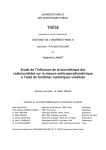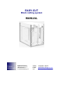
1
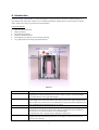
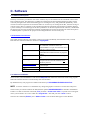
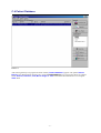
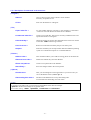
EASY-CUT
Block cutting system
MANUAL
Robert Ströhmann
Medizinische Physik
Schuhstrasse 4
D-23758 Oldenburg i.H.
Telefon
Telefax
E-mail
web
+49 (0)4361 / 494160
+49 (0)4361 / 494161
[email protected]
www.stroehmann-medphysik.de
Content
Page
A. Introduction ........................................................................... 3
B. Hardware
B.1
B.2
B.3
B.4
Package content ............................................................. 4
Recommendations .......................................................... 4
Installation....................................................................... 5
Calibration process ......................................................... 5
C. Software
C.1
C.2
C.3
C.4
C.4.1
C.4.2
C.5
C.5.1
C.5.2
C.6
C.7
C.7.1
C.7.2
Description ...................................................................... 6
Document conventions ................................................... 6
Installation....................................................................... 6
Patient Database
Menubar.......................................................................... 8
- Preferences .................................................................. 9
- Manual control ............................................................ 10
Command buttons
- Import file .................................................................... 11
- Patient Info ................................................................. 12
- Beam Info ................................................................... 12
Edit the shadow ............................................................ 13
-Block Info..................................................................... 14
Create new block .......................................................... 15
Edit a block ................................................................... 15
Cutting the shape.......................................................... 16
Digitizer
Setup 17
Input via Digitizer .......................................................... 17
D. Technical Information
D.1
D.2
D.3
D.4
Mechanics..................................................................... 18
Limits ............................................................................ 18
Maintenance Instructions .............................................. 18
Drawing......................................................................... 19
E. FAQ ...................................................................................... 19
-2-
A. Introduction
The block cutting system EASY-CUT was developed to cut precise block contours for radiation therapy in
Styrofoam blocks. The major intention is to avoid the manual block cutting that was clinical routine in former
times. EASY-CUT helps to produce blocks automatically.
Features & Benefits
•
•
•
•
•
•
space-saving construction
simple operation
uncomplicated software
extensive maintenance-free
laser alignment system for precise block positioning
very slight fume while cutting styrofoam material
Picture 1
Description
Emergency-off switch If any unpredictably events happens than push these button. The device is now
completely disconnected from the power source. After you have solved the problem
first rotate knob 90° to the right side and pull.
To arrange block position in the way that you mount the styrofoam block into the
Laser alignment
clamb. Slightly move the block until the laser beam points to the upper left edge of the
block. In this way you have the correct adjustment to cut precise blocks. Otherwise the
block is adjusted wrong the divergence is not correct.
Indicates functional status of the EASY-CUT device
Power LED
Current LCD-Display This 3-digit LCD display informs you about the actual current of the cutting wire. It is
essential for an accurate and precise cutting that you arrange the current in that way
that you have a very thin cut channel an no rounded edges.
A value between 130 – 180 mA will be sufficient in most cases.
To adjust the current strenght insert the enclosed screw driver into the small hole
Heating adjustment
(alignment potentiometer) then gentle move to the right to increase the current. To
decrease turn to the left.
-3-
B. Installation
B.1 Package contents
•
•
•
•
•
•
•
EASY-CUT device
Parallel port cable
Power cord
CD-ROM with EASY-CUT software for WIN95/98/ME
User manual
5 spare wires
screw driver
B.2 Hardware recommendations
Personal Computer (optional)
For the proper use of the EASY-CUT system we recommend a PC with the following features:
•
•
•
•
•
at least a Pentium Class Processor
min. 32 MB RAM
additional parallel port interface to connect EASY-CUT and a printer at the same time
LAN-Adapter to connect the PC to a network. This makes it much easier to import data files from
treatment planning system
min. 17” Monitor
Digitizer (optional)
EASY-CUT software only provides NUMONICS ACCUGRID Digitizers.
It will be connected to serial port COM 1 or COM 2 to your PC.
For further instructions refer to the manual of the digitzer.
Plotter (optional)
The software provides any plotter that corresponds to the HPGL language.
We recommend Roland DXY 1150A.
-4-
Picture 2
B.3 Hardware installation
1.
2.
3.
4.
Unpack the EASY-CUT device from carton and search a place close to your personal computer.
Connect your EASY-CUT with the power cord on the backside of the device.
Make sure that the Computer and the Easy-Cut device is switched off before you connect the parallel port
cable with your PC and the EASY-CUT device.
Make sure that the cable is properly attached on both sides.
B.4 Calibration process
IMPORTANT!
On first operation with Easy-Cut or when you want to use styrofoam material with different
temperature value start cutting with the highest current (I max) value to avoid damages to the
wire. Otherwise the wire will tear up !
To prepare the EASY-CUT for cutting blocks the first time you must calibrate the heating amps of the wire.
With the screwdriver from the accessory kit turn the potentiometer to its highest position. The potentiometer is
situated on the right side of the current display (Heating-Adjustment). Then start a cutting process as described
below and keep an eye on the area around the wire. While cutting operation gently turn the potentiometer back
until you have a precise contour. Repeat this procedure each time you have changed the wire or styrofoam
material.
-5-
C. Software
C.1 Software Description
The Easy Cut software provides the user with a versatile, easy-to-use interface for the automated control of the
East-Cut Block Cutter. The data import, available for all the main-stream treatment planning systems, ensures
continuity throughout the whole block making process with high accuracy and guaranteed repeatability. In the
clinical enviroment experience has shown that there are several ways of creating block data, from the tracing of
contours using a film on a digitiser to the automated production and transfer straight from a treatment planning
system. The Easy Cut sotware supports all these possibilites. On the developement of the software, consideration
has also been given to the mould room technician with helpful tools such as the printing out of the block plan to
a standard printer or plotter for the purpose of mounting the blocks on an accessory tray.
C.2 Document Conventions
This guide uses the following conventions to help you to locate and identify the information that you need.
Each relevant command within this document is highlighted.
| Program |
< Open index file >
easycut.idx
< Mouse position >
< Source-Surface >
INFO
This is understandable as a topic where other
sub commands will follow and is also
understandable as a topic from the menu bar or
a title of a control window.
This represents a sub command or a sub
command button within menu bar or program
window.
Values or parameters which are editable by the
user.
This text indicates an information, status or
description from a formular field that is not
editable by the user.
This is the convention to enter a value by
keyboard input.
Tip or useful information.
C.3 Software installation
Insert CD into your CD-ROM drive and start the Setup.exe than follow the instructions of the setup program.
When the autostart function is activated setup will start automatic.
By default the Easy-Cut program is installed in the directory C:\PROGRAM FILES\EASYCUT32\..
INFO To use the software in a comfortable way change the graphics resolution to at least 800 x 600 pixel !
The first time you start the software the demonstration patient HANNES BREUER is situated in the database.
If there is no data use the menu command | File | and than < Create new index > a splash screen will appear
where you are asked to save a new index file “easycut.idx”. After that press the < Save > button.
Then use the command | Entries | and < Add to index > now the demo data appears in the database.
-6-
C.4 Patient Database
Picture 3
After starting the Easy-Cut program the main window | Patient database | appears. The patient Hannes
Breuer is for demonstration purposes only ! In the < Loaded dataset > you can see four entries of example
fields. Anterior, Posterior, Test, Mirror image of Test. In the further documentation we are using the
TEST field.
-7-
C.4.1 Description of commands in the menu bar:
| Program |
< About >
Gives a short overview of the software version number.
Necessary for update service.
< Exit >
Will close the EASY-CUT Program
< Open index file >
To open another index file, necessary if the computer is connected to
a network. The index file has the character of a database.
< Create new index file >
Creates a new index file. This may be necessary if different users will
operate the EASY-CUT Program
< Check validity >
Checks all entries for missing files and marks these in the first column
of the table. <OK> indicates a good status.
< Correct errors >
Removes invalid entries found by the previous menu point
< Import >
With this command you can import block data from different planning
system. For a further description see <command buttons>
| File |
| Entries |
< Add to index >
This command enables you to add an existing patient to the index file.
< Remove from index >
Deletes the marked entry from the database
< Enter new patient >
Creates a new patient file in the database
< Save Entry >
Saves the changes made to the current patient
| Options |
< Preferences >
Here you can manage the colour appearance at your choice also you
can set the default values. (refer to pic. 4)
< Descending Sort order >
The data in the database will sort by descending order.
A hook marks the descending sort order status.
INFO
To sort data in the table when you left click into the headline of the table for example
< patient > the table will change sort by patient name.
You can also sort by : <date>, <plandate>, <comments> and <filename>.
-8-
C.4.1 Description of commands in the menu bar:
Picture 4
<Default import format>
| Import options |
<Dates>
<Mirror data>
Here you can arrange your TPS by default.
swap day and month some TPS are exporting the Plandates in the English date
convention so you can fix this problem.
On some TPS the data is exported mirrored. Marking the checkbox will arrange
the correct orientation.
| Mirror function |
With this option field you can manage the mirror direction
| Colors in edit window |
This is only for the color appearance of the Edit the shadow window. You can
make changes to your satisfaction.
<Default distances>
Here you can manage the distances of Source-Surface and Source-Tray. They
are only need to be changed one time because of using the same Accelerator
Type.
<Aperture margin>
Only necessary for Dosigray or Isis 3d. The distance between radiation field and
the shielding.
<Wirecutter Port>
Specifies the parallel port number where the EASY-CUT device is connected to
the computer. When you have an additional parallel port adapter you can also
change to LPT 2 or LPT 3.
<HPGL export>
These values determines the origin of the tray holder. Because of different types
of tray holders values must be entered once.
<Scale>
Setting for resolution of the plotter. 40 pts./mm is the default value.
<Plotter>
Specifies the plotter that is connected to the computer.
-9-
C.4.1. Description of command in the menu bar:
| Manual Control |
Here you can control the motors manually. This is necessary when an error occurs while
EASY-CUT is cutting a block. After activation of these command the following
window will appear:
Picture 5
< Move to park-position >
Moves the stepper motors automatically into their mechanical zeroposition.
< Link the two sides >
If this option is checked the motors will drive in parallel. This is
necessary to ensure that you do not tear the wire by moving only one
side.
< Step width >
Enters the step width in mm (0.1, 1, 5, 10, 50, and 100 mm)
< Speed >
Controls the rate of the motors. Make sure that this is not set too high, as
the wire might otherwise lag behind the desired course or even break.
< Side (A/B) direction buttons > With the up/down and closer/further buttons you are able to move each
stepper-motor separately. To stop the motors immediately, click onto the
button in the middle of the direction-buttons. This is like an emergency
button. It may be necessary when you set a large stepwidth or the motors
are driving too fast.
< Side A/B >
In the bottom of this window you can see four control fields indicate the
coordinates. The accuracy is 1/10 mm.
< Set as 0 >
Set the coordinates in the software to zero values. This may be necessary
when the motors have been moved by hand or the software restarted
while the motors where not in their park-position.
- 10 -
C.4.2 Description of command buttons in patient database window :
< Load block data >
< Import file >
Loads the data of the marked database entry. Alternative you can do this by a
double-click to the patient in database list.
Now you see that the „Loaded dataset“ window shows some further information.
The example patient consists of four different blocks. In the documentation the
„TEST“ block is used to describe the different ways to edit block in a field.
Imports block data from different treatment planning systems like
ISIS, PINNACLE, BRAINLAB, HELAX, MULTIDATA, DOSIGRAY,
CADPLAN, HEK, ISIS (Version 3d), FOCUS-CMS
(Refer to pic. 6)
Picture 6
- 11 -
C.4.2 Description of command buttons:
Picture 7
< New Patient >
Here you can create a new patient with all relevant data. The plan date is set
automatically by the software to the current date. (Refer to pic. 7)
LNote: You can use the < TAB > key to enter each field.
< Beam info >
Picture 8
<Description>
The description of the field is editable.
<Distances>
< Source-Surface > means the distance of the beam source to patient (or film) surface.
< Source-Tray > distance of block tray holder bottom edge to beam source
The default values are taken from the < Preferences > settings.
<Radiation field>
Specifies the radiation field dimensions
< Left > = X-coordinate of the upper left corner of the field
< Top > = Y-coordinate of the upper left corner of the field
< Width > specification of field width
< Height > specification of field height
| Edit blocks |
Skips to the Edit the shadow window (closer specified in chapter C.2.)
| New beam |
Creates a new field in the existing patient dataset.
| Mirror beam |
Creates a mirrored block automatically. To arrange a mirror block mark the
corresponding block in the <Loaded data set> field and click the <Mirror beam>
button. Then a new block with a prefixed „Mirror of ...“ appears.
- 12 -
C.5 Edit the shadow
A double click to the left-mouse button on the example patient in the <Loaded data set> field will list the
different block contours. Now with a double click on TEST the program changes to the | Edit the shadow |
window. (Ref. to Pic. 9)
Picture 9
< Back to patient DB >
Returns to the | Patient database | window
< Zoom >
Magnifies the image in 5 steps by pressing and holding the mouse cursor on the
scroll bar. You can also use the <+> and <–> keys to zoom in and out.
< Mouse position >
Shows the position of the mouse with an accuracy of 1/10 mm. This is helpful when
you arrange or edit blocks by mouse input.
Same window as beam info refer to description of Beam Info above.
Here you can verify the basic data. You also have a chance to correct errors.
Regarding wrong Name, date of birth etc..
< Available blocks >
This status field is a list of the available blocks in the actual field. The example
consist of four Blocks. When you left click on the corresponding block the display
will highlight the marked block contour. In this case the red marked „T“.
Opens the | block info | window that will show you further information.
Refer to next page.
- 13 -
C.5 Edit the shadow
< Description >
< Divergent >
< Data source >
Editable field to change the description of the block
To arrange that block will be cut divergent
Indicates where the block has it’s creation source
There are three different types:
• Mouse • Digitizer • Named TPS
Using this command button creates an aperture under consideration of the
weight of the blocks. You will be asked if you want to limit the weight of
the blocks. Later you will be asked if you want to remove the old aperture.
Confirm in both cases.
Removes the marked block from the field arrangement.
Enables you to create a new block with the mouse. By pressing this button
you will be asked for the new block data. The program creates a new block
automatically. Now the mouse cursor changes to a small circle. You can
add new points to the contour by pressing the left mouse button.
(Refer to pic. 10+11)
Closes the contour. The program draws a line to the origin to close the
block.
Refer to chapter C.4.
Refer to chapter C.3.
Prints out the contours. You can use the printout for positioning the blocks
on the tray.
Generates a HP/GL code for the connected plotter.
- 14 -
C.5 Edit the shadow
C.5.1 Create a new block
Picture 10
Picture 11
C.5.2 Edit a block
You have the option to change existing contours subsequently.
- Hold down the < Shift >-key and move the mouse-cursor to an edge of the contour then press and hold down
the left mouse key.
Now a small circle with arrowed cross hair appears. You can move the vectors by moving the mouse. By
pressing the right mouse button next to a contour you can add a point into the middle of the vector
Picture 13
Picture 12
- 15 -
C.6 Cutting the shape
Picture 14
< Foam dimensions >
< Safety margin >
To enter the foam block dimensions in mm.
Set a safety margin within the foam block to avoid cutting within the possibly
frayed edges.
90 ° turning of the foam block
Foam movement
Block movement
Block movement into one edge under consideration of the safety margin
< Cut Block >
< Cut Plan >
< Speed >
< Delay between sides >
< Show both faces >
< Zoom out >
Cuts the active block only
Cuts all blocks
Move the slider to set the cutting speed
Sets a short delay between cutting the separate edges. This may be necessary to
avoid round edges when moving fast.
Shows both sides of the block.
Magnifies the display
- 16 -
C.7 Digitiser setup
7.1 Digitizer Setup
Picture 15
< Communication >
< Port >
Set the COM Port, which the digitiser is connected to. (normally COM 1 or COM 2)
Do not make any changes to the other values like Baudrate, Data bits, Parity etc.
unless your digitiser has been set differently.
Other parameters
are functional default values and need no changes!
C 7.2 Digitzier input
1. Press button 1 of digitizer cursor. A short "beep" sound will confirm that the digitizer is ready for the input.
2. Move cursor to the top point of the x-ray image and press button 2 of digitizer cursor. This step is necessary
for the orientation.
3. Now the digitizer is calibrated for tracing contours.
Press the < OK, start tracing the contour > button. The programm changes to the edit the shadow window.
You can follow the tracing procedure on the screen.
- 17 -
D. Technical Information
Dimensions:
Weight:
Width: 395 mm
Height: 565 mm
Length: 610 mm
app. 35 kg
Power supply:
~110/230 Volt, 50/60 Hz, 80 VA
Resolution of the stepper motors:
Max. cutting range:
Max. styrofoam block size:
Styrofoam block width:
0,005 mm
320 x 320 mm
450 x 450 mm
20 – 100 mm
Diameter of wire:
0,05 mm
D.1 Mechanic of EASY-CUT
•
•
•
•
•
•
•
•
•
CNC-milled aluminium parts
Tempered, filed precision steel shafts, 12mm diameter
PTFE-plated sinter-bonze precision slide bearing bolts
Infeed spindles on bearings, with 2 mm pich, pich accuracy 100 µm / 100 mm
Free-of-play plasic infeed nuts
Cog belt to synchronize the two infeed spindles
Stepper motor drive with 16 Ncm torque and 400 half steps per revolution
Theoretical resolution 2 / 400 mm or 1 / 1200 mm = 0.005 mm
Typical accuracy < 0.05 mm
D.2 Mechanical Limits
From approx. 4000 steps per second the stepper motor torque drops. Such high step frequencies never occur
when cutting styrodur.
At a certain critical speed the relatively long drive spindles may start to resonate. Make sure when positioning
the wire that a critical speed is not reached, as otherwise it could lead to step loss. It is best to drive the EASYCUT with a speed range of 8 in the software.
The maximum speed is around 3000 steps per second, wich corrosponds to approx. 15 mm per second or 900
mm per minute. In practice, the cutting speed for styrodur is approx. 150 mm per minute.
D.3 Maintainance instructions
Lubricate the spindels in a period of half a year. Use a resin-free and non-acidic sewing machine oil.
- 18 -
D. Technical Information
D.4 Drawings
Picture 16
E. FAQ – Frequently asked questions:
Q. While cut procedure Easy-Cut lost steps is it due to the software ?
A. No – after a long period of using the device the vibrations can unlock the parallel port cable when it is not
properly plugged in this case data stream is not granted. Ensure you that the screws at the parallel port
connector are fixed. On the other hand it could be a mechanical problem due to lubrication of spindels.
Refer to maintainance instructions in Chapter D.3.
Q. We have the problem that blocks have round edges.
A. Reduce cutting speed or arrange a delay of 0.5 sec. or more in the cutting the shape windows
Q. We are using a switch box because we have attached a plotter and a printer to the computer – Why does it
work properly ?
A. It works properly – but before you switch on you computer you must consider whether you want plot or
print. This is a handshake problem of the computer hardware. To avoid this we recommend that you install a
third parallel port interface into you computer.
Q. We are using ISIS 3d TPS. We want to create a aperture. But the “create aperture” button is not functional.
A. ISIS 3d generates automatically an isocenter cross in the middle of the block or field. Go to “Edit the
shadow” window delete the cross than the software can arrange an apperture.
Q. We are using a digitizer but there is no chance to create a contour.
A. Make sure that you switch on your digitizer before the computer.
- 19 -