1
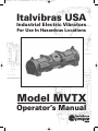
MVTX Manual (12-2-11).qxd:MTVX Manual (12-2-11)
12/2/11
2:55 PM
Page 1
Italvibras USA
Industrial Electric Vibrators
For Use In Hazardous Locations
Model MVTX
Operator’s Manual
MVTX Manual (12-2-11).qxd:MTVX Manual (12-2-11)
12/2/11
2:55 PM
Page 3
Table of Contents
Section Title
Page
Tables and Figures Index . . . . . . . . . . . . . . . . . . . . . . . . . . . . . . . . .Below
Introduction . . . . . . . . . . . . . . . . . . . . . . . . . . . . . . . . . . . . . . . . . . . . . . . . .2
Installation Design Tips . . . . . . . . . . . . . . . . . . . . . . . . . . . . . . . . . . . .3-10
Eccentric Weight Adjustment . . . . . . . . . . . . . . . . . . . . . . . . . . . . . . .11-12
Lubrication requirements . . . . . . . . . . . . . . . . . . . . . . . . . . . . . . . . . . . .13
Electric Vibrator Repair & Maintenance . . . . . . . . . . . . . . . . . . . . . . . .14
Appendix
Electric Vibrator Item Numbers . . . . . . . . . . . . . . . . . . . . . . . . . . . . . .A1
Electric Vibrator Torque Requirements . . . . . . . . . . . . . . . . . . . . . . . .A1
Electric Vibrator Parts List Diagrams . . . . . . . . . . . . . . . . . . . . . . . .A2-3
Figures
Figure #
1
2
3
4
5
6
7
8
9
10
11
12
Page
Mounting Bolt Torque Sequence . . . . . . . . . . . . . . . . . . . . . . . . . . .4
Nameplates . . . . . . . . . . . . . . . . . . . . . . . . . . . . . . . . . . . . . . . . . . . . . .5
Wiring Diagrams . . . . . . . . . . . . . . . . . . . . . . . . . . . . . . . . . . . . . . . . .6
Proper Wiring Arrangement/Positioning . . . . . . . . . . . . . . . . . . . .7
Terminal Block Hardware Installation . . . . . . . . . . . . . . . . . . . . . .7
Wiring Block Assembly . . . . . . . . . . . . . . . . . . . . . . . . . . . . . . . . . . .8
Manual Reset Connections . . . . . . . . . . . . . . . . . . . . . . . . . . . . . . . .9
Ground Bonding Screw . . . . . . . . . . . . . . . . . . . . . . . . . . . . . . . . . .10
Removing the Weight Covers . . . . . . . . . . . . . . . . . . . . . . . . . . . . .11
Weight Fastener . . . . . . . . . . . . . . . . . . . . . . . . . . . . . . . . . . . . . . . . .11
Setting Sets of Eccentric Weights to Mirror Images . . . . . . . . . .11
Eccentric Weight Adjust . . . . . . . . . . . . . . . . . . . . . . . . . . . . . . . . . .12
Tables
Table
I
II
III
IV
Page
Mounting Bolt & Torque Requirements . . . . . . . . . . . . . . . . . . . . .4
Lubrication Schedule for Each Bearing . . . . . . . . . . . . . . . . . . . .13
Vibrator Item Number By Frame . . . . . . . . . . . . . . . . . . . . . . . . .A1
Vibrator Nut & Screw Torque Requirements . . . . . . . . . . . . . . .A1
© 2011 Italvibras USA
All rights reserved.
All materials subject to change.
12/11
MVTX Manual (12-2-11).qxd:MTVX Manual (12-2-11)
12/2/11
2:55 PM
Page 4
Introduction
Italvibras USA explosion-proof and dust-ignition-proof industrial electric vibrators have been
designed and manufactured in accordance with the most exacting international industrial
standards and requirements. Italvibras USA industrial electric vibrators are designed for long
life at continuous duty and maximum force output. The electric vibrators are suitable for
operation in ambient from -25°C to 40°C for Class I and Class II electric vibrators and for
operation in ambient from -25°C to 55°C for Class I electric vibrators.
Italvibras USA industrial electric vibrators have been evaluated for installation throughout the
world. Standard ratings include Underwriter’s Laboratories, Inc. (UL) Listing, CSA (Canadian
Standards Association) Approval, the CE (European Directive) Mark, EX Approval for Zone 1, 2,
21, 22 (ATEX II2GD, Ex d IIB T 120°C Gb, Ex t IIIC T120°C Db, IP66) and IECEx Approval (Ex d
IIB T120°C Gb, Ex t IIIC T120°C Db, IP66). Check the electric vibrator nameplate for the exact
ratings and Approvals for the specific Model.
The electric vibrator can be referred to by its Model or Type designation or by its Item number.
The vibrator Model or Type designations referred to in this manual are as follows:
MVTX - Continuous duty explosion-proof industrial three phase electric vibrator.
The Italvibras USA explosion-proof electric vibrator is intended for the following hazardous
locations:
In areas that have explosive or flammable gases, vapors and/or dusts where the explosion
hazard is referred to as Division 1 or Zone 1, the electric vibrator is marked for Class I, Groups
C and D and Class II, Groups E, F and G hazardous locations and Ex d IIB T120°C Gb and
Ex t IIIC T 120° Db.
In areas that have explosive or flammable gases and/or vapors where the explosion hazard
is referred to as Division 1 or Zone 1, the electric vibrator is marked for Class I, Groups C
and D hazardous locations and Ex d IIB T160°C Gb.
Italvibras USA MVTX explosion-proof electric vibrator complies with the Essential Health and
Safety Requirements: EN 60079-0:2009, EN 60079-1:2007, EN 60079-31 :2009,
IEC 60079-0:2007, IEC 60079-1:2007, IEC 60079-31 :2008.
2
MVTX Manual (12-2-11).qxd:MTVX Manual (12-2-11)
12/2/11
2:55 PM
Page 5
General Safety requirements
Read this entire manual before proceeding. Compliance with all company, local and OSHA
regulations is essential. Any electrical work must be done in accordance with all applicable
local and national codes and must be performed only by qualified, licensed and authorized
personnel. Always follow lockout and tag out procedures and requirements and always wear
ear protection when in close proximity to operating vibratory equipment.
Comprehensive adherence to these documents at a minimum is required – The National
Electrical Code NFPA 70, ANSI z244.1 the American National Standard for Personnel Protection
– Lockout/Tag out of Energy Sources – Minimum Safety Requirements, CFR 29 Part 1910 –
Control of Hazardous Energy Sources (Lockout/Tag out) Final Rule and CFR 29 Part 1910.15
Occupational Noise Exposure.
Dimensions of flame-proof joints are other than the relevant minimum or maximum specified
in Table 2 of EN 60079-1:2007. Vibrators are marked with an “X” and manufacturer’s Drawing
Nos. 601531, 601534 and 601536 detail the dimensions of the flame-proof joints.
Storage
Storage of the electric vibrator should be in an ambient not less than 5°C with a relative
humidity not more than 60%. If the vibrator has been stored for longer than two years, the
vibrator should be evaluated by authorized and trained personnel to ensure that the grease is
intact, that there is no bearing damage such as brinelling and that the ground insulation is
sound and not damaged from condensation.
Installation
Before installing the vibrator, make sure that you have everything that you will need and that
there is no shipping damage. Any product damage should be reported to the delivery service
immediately. Standard metric hand tools will be needed. Carefully handle the electric vibrator.
Dropping or impacting the electric vibrator may damage the bearings.
Welding – Never weld on a machine with the electric vibrator mounted to it since the welding
may damage the vibrator bearings or electrical circuits. When you do weld, especially in an
enclosed area, make sure that the area is known to be nonhazardous and that there are no
flammable or explosive levels of gases, vapors or dusts.
Mounting Surface – The object of vibration is to transmit vibration energy through the structure
to the material within. The mounting surface must be rigid and strong for this transfer of energy
to take place. The mounting surface must also be clean, flat (0.010 in. across mounting feet
maximum), free of paint and have a minimum thickness equal to the major diameter of the
mounting bolt. The mounting plate should be at least the overall size of the electric vibrator feet.
Also make sure that the electric vibrator feet are clean and free of debris.
3
MVTX Manual (12-2-11).qxd:MTVX Manual (12-2-11)
12/2/11
2:55 PM
Page 6
Mounting Hardware & Torque
Always use new bolts, nuts and compression washers. The bolts should be Grade 5 or 8
(equivalent international designation is 8.8 and 12.9, respectively). Grade 5 bolts are suitable
for a majority of applications. Do not use split lock washers. Use only compression washers.
Table I offers suggested mounting bolt torque values. Always check with the bolt manufacturer
for recommended torque values. Torque the mounting bolts in the proper sequence as shown
in Figure 1 so as not to damage casting. After operating vibrator for 15 minutes, disconnect,
lockout/tag out, and torque the mounting bolts a second time. Periodically check the mounting
bolt torque thereafter.
Table I. Mounting Bolts & Torque Requirements
Bolt Size
1 in-8 NC
645
M24
89
80
7/8 in -9 NC
430
M22
56
90
3/4 in -10 NC
288
M20
38
Bolt Size
MVTX
70
MVTX
MVTX
1
70 Frame
80 Frame
7
Dry Torque (kgm),
Grade 8.8
3
4
7 1
2
3
5
6
2
8
4
1
Figure 1. Torque Sequence
6
Metric
Dry Torque (ft-lb) ,
Grade 5
Frame Size
90 Frame
British
3
2
4
4
5
8
MVTX Manual (12-2-11).qxd:MTVX Manual (12-2-11)
12/2/11
2:55 PM
Page 7
Vibrator Nameplates
Stainless Warning Name Plate For
Explosion Proof Vibrators
Item #518497
Stainless Name Plate For
Explosion Proof Vibrators,
Item #519003
MVTX G/D - Stainless Name Plate
MVTX G - Stainless Name Plate
Figure 2. Nameplates
5
MVTX Manual (12-2-11).qxd:MTVX Manual (12-2-11)
12/2/11
2:55 PM
Page 8
Wiring Electric Vibrator
It is mandatory to comply with the National Electrical Code, NFPA 70, and all applicable local codes.
Remove the screws with washers securing the wiring box cover along with the foam rubber block and
set aside. Identify the wiring diagram by referencing the wiring diagram found within the wiring box or
by referring to the diagrams shown in Figure 3.
W2 U2
V2
W2
U2
U1
V1
W1
G
U1
P1 P2
4 75 8 6 9 1 2 3
V2
W1
V1
G
P1 P2
MTVX Model, 9-lead, 3-phase
P1 P2
P1 P2
MTVX Model, 6-lead, 3-phase
U V
1 72 8 3 9 4 5 6
Diagram A
W
G
Cable Entry
Y - High Voltage
V
U
W
G
Cable Entry
Y (S) - High Voltage
S - Low Voltage
Diagram B
Figure 3. Wiring Diagrams
YY - Low Voltage
Select a 4-conductor cord for Class I only electric vibrators. Select a 6-conductor cord for Class
I and Class II vibrators. The cord type shall have a voltage rating not less than the power supply
voltage and a minimum temperature rating of 105°C. We recommend Coleman black cord
SEOOW Seoprene cable rated 600 V and 105°C. Coleman Cable Inc. can be reached by phone
at 847-672-2300 or at www.colemancable.com. Italvibras USA also stocks the Coleman cable.
When wiring the electric vibrator, leave enough slack in the cord so that the cord does not
become taut during operation causing stress on the connections. It is always best to position the
cord down so that should there be any moisture present the moisture would tend to run down
instead of into the vibrator wiring box.
Trim the cord by removing the jacket exposing the conductors and ground wire for approx. 6
in. Be careful not to cut the conductor or ground wire insulation. Insert the cord through the
conduit fittings and then through the opening in the side wall of the wiring compartment.
Position the jacket of the cord approx. ½ in beyond the inside wall of the wiring box wall.
Assemble all conduit fittings making sure that there is always minimum thread engagement of
5 full threads. Install the conduit seal following all instructions being certain to comply with
Articles 501 and 502 of the NEC.
6
MVTX Manual (12-2-11).qxd:MTVX Manual (12-2-11)
12/2/11
2:55 PM
Page 9
Wiring Electric Vibrator Cont.
Trim the conductors within the wiring box leaving plenty of slack. Next, strip the conductor
insulation for ¼ in. to 3/8 in. Crimp on closed loop wire connectors. Use only the intended
crimping tool as designated by the wire connector manufacturer. The conductors should be
neatly arranged on the floor of the wiring box. The wires should not cross over each other. See
Figure 4.
Figure 4. Proper Wiring Arrangement/Positioning
Secure the wire connectors and the shorting bars to the terminal block in the positions shown
on the wiring diagram using the hardware provided. It is essential that the hardware be
positioned as shown in Figure 5.
Figure 5. Terminal Block Hardware Installation
7
MVTX Manual (12-2-11).qxd:MTVX Manual (12-2-11)
12/2/11
2:55 PM
Page 10
Wiring Electric Vibrator Cont.
Note that the closed loop wire connectors provided on the power supply cord are positioned
between the two flat washers. A drop or two of thread sealant such as Locktite is recommended.
Do not use permanent thread sealant because the terminal block will be damaged should you
wish to remove and replace the power supply cord. The terminal block nuts should not be over
tightened since the possibility of damaging the plastic insulating body is high. Reference
table III in the Appendix for torque values. Make the connections hand-tight followed by a ¼
turn but never put a ratchet on these nuts.
For constructions that do not incorporate terminal blocks, make the wire-to-wire connections
using wire nuts. The nuts should be taped with electrical insulation.
Electric vibrators for use in Class I and Class II hazardous locations will include a small 2-pole
terminal block in the wiring box. This is the thermostat circuit. Proceed to Thermostat Wiring.
Class I electric vibrators do not include this circuit. For Class I electric vibrators, reinstall the
rubber block over the power supply conductors and install the wiring box cover being careful
not to pinch the O-ring. Screw torque is specified in the Appendix. Reference Figure 6.
Figure 6. Wiring Block Assembly
8
MVTX Manual (12-2-11).qxd:MTVX Manual (12-2-11)
12/2/11
2:55 PM
Page 11
Thermostat Wiring
Class I and Class II electric vibrators have thermostat circuits installed in the winding. The thermostat
terminals are identified as P1 and P2. These devices are intended to limit surface temperatures to no
more than the marked operating temperature (code). Connect the thermostats to the motor starter as
shown in Figure 7. The thermostat circuit is rated 600 V ac maximum and 720 VA. Use a manual
momentary start switch.
Disconnect
Phase C
Phase B
Phase A
Fuse
F5
Fuse
F4
Fuse
F1
Fuse
F2
Fuse
F3
Primary
Transformer
Secondary
X1
MS1
X2
Fuse
F5
1
Primary
Start
Stop
1
2
MS1
3
2
Coil
2
P2
P1
OL
OL
OL
3
Figure 7. Manual Reset Connections
MS1
Reinstall the rubber block over the power supply and thermostat circuit conductors and install the wiring
box cover being careful not to pinch the O-ring. Screw torque is specified in the Appendix. See Figure 6.
Grounding & Bonding
The electric vibrator must be grounded using the ground wire
provided in the cord. The ground wire shall be connected to a
closed loop wire connector which is then connected to the ground
terminal located within the wiring box (See Figure 4). The ground
terminal is identified by the international symbol.
GROUND
It may be necessary to bond the electric vibrator to ground using the external ground screw
as shown in Figure 8. The external ground terminal is identified by the international symbol.
Use a wire size no smaller than the internal ground wire.
9
MVTX Manual (12-2-11).qxd:MTVX Manual (12-2-11)
12/2/11
2:55 PM
Page 12
Grounding & Bonding Cont.
Figure 8. Ground Bonding Screw
Overload, Short-Circuit & Ground-Fault Protection
In the USA, The National Electrical Code, NFPA 70, and all applicable local codes, govern how
to properly size, select and install overload protection (sometimes called heaters) and shortcircuit and ground-fault protection (fuses or circuit breakers). Proper selection and installation
of these devices is required and essential for not only protection of the electric vibrator and the
power supply circuit but also for protection of personnel.
If the overload or short-circuit and ground fault protection operate, have qualified personnel
locate and fix the problem before resetting.
When operating two electric vibrators, the vibrators should be controlled with a single motor
starter that has overload protection dedicated to each electric vibrator. The overloads shall be
electrically interlocked such that should there be a fault with one electric vibrator, both electric
vibrators will be de-energized.
Variable Frequency Inverter
The electric vibrators may be supplied with a variable frequency inverter. Never operate the
vibrators above the maximum frequency noted on the nameplate. If operating two vibrators,
use one variable frequency inverter along with overload protection dedicated to each electric
vibrator. The overloads shall be electrically interlocked such that should there be a fault with
one electric vibrator, both electric vibrators will be de-energized.
The nameplate current should never be exceeded throughout the entire frequency range.
10
MVTX Manual (12-2-11).qxd:MTVX Manual (12-2-11)
12/2/11
2:55 PM
Page 13
Eccentric Weight Adjustment
The eccentric weights may be adjusted to produce the desired centrifugal force output. It is
always best to operate the electric vibrator at the lowest weight setting that produces the desired
result. This will result in lower energy expense and extend the bearing life. To adjust the force
output, lockout/tag out the electric vibrator. Remove each weight cover and set it and the screws,
washers and O-rings aside. Reference Figure 9. The outer adjustable weight clamping screw
may be loosened and then the adjustable weights may be rotated to the desired position.
Reference Figure 10.
Figure 9. Removing the Weight Covers.
Figure 10. Weight Fastener
The eccentric weights must be adjusted to mirror images of each other at the same setting
number as shown in Figure 11.
OK
Figure 11. Setting Sets of Eccentric Weights to Mirror Images.
11
MVTX Manual (12-2-11).qxd:MTVX Manual (12-2-11)
12/2/11
2:55 PM
Page 14
Eccentric Weight Adjustment Cont.
Properly torque the clamping screw to secure the weights in position. Torque values are
outlined in the Appendix. Reference Figure 12. Reinstall the weight covers making sure not to
pinch the O-rings.
Check shaft rotation before replacing weight covers. Start vibrator for 1 second, stop and
lockout/tag out. Observe direction of rotation. If desired to reverse the direction of rotation,
switch two of the three power supply leads in the wiring box or at the motor starter.
Replace weight covers using screws and washers being careful not to pinch the O-rings. The
screw torque is outlined in the Appendix. Never operate the electric vibrator without weight
covers in place. They provide a degree of protection for the bearings and a shield for the rotating
eccentric weights. Always replace broken weight covers immediately. Do not operate electric
vibrator with weight covers removed or with damaged weight covers.
Figure 12. Eccentric Weight Adjust.
Starting Up
After making sure that the power supply voltage matches the voltage marked on the nameplate,
that the mounting bolts are properly secured, that all covers are in place and secured, and that
the motor starter is properly installed and adjusted, turn the electric vibrator on. Excessive
noise would indicate a problem but slight bearing noise is normal due to the type of bearing
used. After a few hours of operation, check each line current and verify that it does not exceed
nameplate current. If the line current exceeds the nameplate current, then the mount needs to
stiffened, the vibrator weights need to be reduced or the vibrator needs to be moved to a more
rigid location. Never operate the vibrator above nameplate current.
After the first 8 hours of operation, check the line current to make sure that it does not exceed
nameplate and check mounting bolt torque. See MOUNTING HARDWARE AND TORQUE.
12
MVTX Manual (12-2-11).qxd:MTVX Manual (12-2-11)
12/2/11
2:55 PM
Page 15
Electric Vibrator Lubrication
All electric vibrators are lubricated at the factory. If there are no external grease fittings, then
the vibrator construction is lubricated for life. No grease ever need be added to these electric
vibrators. If external grease fittings are provided, then it is intended that the bearings be
periodically lubricated. The lubrication schedule is outlined in Table II.
Table II. Lubrication Schedule For Each Bearing
Frame Size
Grease Quantity, g
Lubrication Frequency, hrs.
80
50
2000
70
90
26
70
2000
2000
The lubrication frequency is every 2000 hours of operation unless specified otherwise in the
table. There is an exception - 3600 rpm electric vibrators operating continuously or for long
periods of time should be lubricated in ½ the time specified using ½ the grease volume
specified. For all other vibrators, follow the table except when the operating temperature
exceeds 90°C. If the operating temperature exceeds 90°C, reduce the lubrication frequency and
lubrication volume by 50% for every 10°C increment above 90°C. If the electric vibrator
operating temperature exceeds 100°C, contact Italvibras USA by phone at 815-872-1350. The
electric vibrator should never operate above 120°C.
When adding grease through the grease fitting, make sure to clean the fitting so as not to
introduce dirt into the bearing. Add the specified amount of grease. Experiment with your
grease gun to determine how many grams are introduced with each pump. Never over-grease
a bearing since this will damage the bearing and cause high operating temperature.
Always use the correct grease. Never mix greases. Use Kluber ISOFLEX TOPAS NB 52 grease.
Kluber grease may be purchased direct from Kluber Lubrication by calling 800-447-2238.
Italvibras USA also stocks the Kluber grease.
13
MVTX Manual (12-2-11).qxd:MTVX Manual (12-2-11)
12/2/11
2:55 PM
Page 16
Electric Vibrator Repair
If the electric vibrator needs repair, contact Italvibras USA at 815-872-1350 for instructions. Most
electric motor repair shops are not trained to repair our industrial electric vibrators. We
recommend that they be returned to the service center located in Princeton, IL. Attempting to
repair the electric vibrator or replace the bearings will void the warranty.
Electric Vibrator Maintenance
Every quarter, we recommend a thorough inspection of the electric vibrator. After lockout/tag
out, do the following:
1.) Inspect the cord for any visible damage or wear. Replace the cord if there are any
signs of damage or wear. This holds true for both the power supply cord and the
thermostat circuit cord.
2.) Remove the wiring box cover and inspect for any foreign matter or liquid.
Vacuum any foreign matter. If wet, remove electric vibrator from service and
have the ground insulation tested by a trained, qualified and licensed technician.
3.) Before replacing the wiring box cover, make sure the electrical connections are
tight (do not over-tighten) and inspect the cover O-ring and rubber compression
block. If the O-ring or rubber compression block is damaged or if they have lost
their compression set, replace them.
4.) Remove each weight cover and inspect for foreign matter. Vacuum if necessary.
Replace O-rings if they are damaged or if they have lost their compression set.
5.) Check the mounting bolt torque.
6.) Replace any broken parts.
14
Appendix
MVTX Manual (12-2-11).qxd:MTVX Manual (12-2-11)
12/2/11
2:55 PM
Page 17
Electric Vibrator Item Numbers
The table below outlines a list of electric vibrator Model/Type designations next to their
respective Item No. The information is sorted by frame size. Please reference the Model/Type
designation and Item No. when ordering electric vibrators or their parts.
Table III. Vibrator Item Numbers By Frame
Frame No.
Model
Item No.
70 Frame
MVTX
18-7700
601531
80 Frame
MVTX
18-10900
601534
90 Frame
MVTX
18-17000
601536
Electric Vibrator Torque Requirements
Table IV. Vibrator Nut & Screw Torque Requirements
Cap Screws
ft/lb (kgm)
Terminal
Block Nuts
M8
16.5 (2.3)
M5
M12
58 (8)
M6
M10
M14
7 (1)
35 (4.8)
95 (13)
M16
137 (19)
M20
275 (38)
M18
M24
ft/lb (kgm)
Weight
Screw
ft/lb (kgm)
1.45 (0.20)
M10
57 (7.9)
4.70 (0.65)
M14
M4
0.87 (0.12)
M6
2.17 (0.30)
M8
M10
9.80 (1.35)
195 (27)
470 (65)
A-1
M8
M12
28 (3.9)
97 (13.5)
157 (21.8)
1 - -CASE
2 - -STATOR
3 - -BEARING FLANGE
4 - -SCREW
5 - -SCHNORR WASHER
7 - -SHAFT
10 -BEARING
13 -SHAFT KEY
14 -(S) LEFT FIXED WEIGHT
14 -(D) RIGHT FIXED WEIGHT
15 -(S) LEFT ADJUSTABLE WEIGHT
15 -(D) RIGHT ADJUSTABLE WEIGHT
16 -SCREW
17 -SCHNORR WASHER
20 -EXTERNAL SNAP RING
22 -O-RING
23 -WEIGHT COVER
24 -SCREW
25 -SCHNORR WASHER
26 -TERMINAL BLOCK
27 -SCREW
28 -SCHNORR WASHER
29 -GROUND SCREW
31 -SET SCREW
32 -RUBBER COMPRESSION BLOCK
33 -O-RING
34 -WIRING BOX COVER
35 -SCREW
37 -CONDUIT PLUG
39 -LEAD PROTECTOR
40 -INTERNAL SNAP RING
46 -BEARING COVER
47 -SCREW
48 -SCHNORR WASHER
49 -THERMISTOR TERMINAL BLOCK
50 -SCREW
51 -ADAPTER SCREW
53 -SCREW
54 -SCHNORR WASHER
64 -SCREW
69 -WASHER
70 -SCREW
77 -INSPECTION PLUG
83 -SET SCREW
84 -DOWEL PIN
90 -END HOUSING
Part# - -Description
601531
23
27
22
39
29
26
32
33
35
49
90
53
54
64
20
28
50
70
51
34
17
69 15S
16
14S
4
5
22
3
22
13
84
7
2
37
83
A-2
10
46
14D 15D
90
40
2:55 PM
31
1
29 28
12/2/11
24
601534
80 Frame
70 Frame
Item Numbers;
MVTX Manual (12-2-11).qxd:MTVX Manual (12-2-11)
Page 18
1 - -CASE
2 - -STATOR
3 - -BEARING FLANGE
4 - -SCREW
5 - -SCHNORR WASHER
7 - -SHAFT
10 -BEARING
13 -SHAFT KEY
14 -(S) LEFT FIXED WEIGHT
14 -(D) RIGHT FIXED WEIGHT
15 -(S) LEFT ADJUSTABLE WEIGHT
15 -(D) RIGHT ADJUSTABLE WEIGHT
16 -SCREW
17 -SCHNORR WASHER
20 -EXTERNAL SNAP RING
22 -O-RING
23 -WEIGHT COVER
24 -SCREW
25 -SCHNORR WASHER
26 -TERMINAL BLOCK
27 -SCREW
28 -SCHNORR WASHER
29 -GROUND SCREW
31 -SET SCREW
32 -RUBBER COMPRESSION BLOCK
33 -O-RING
34 -WIRING BOX COVER
35 -SCREW
37 -CONDUIT PLUG
39 -LEAD PROTECTOR
40 -INTERNAL SNAP RING
46 -BEARING COVER
47 -SCREW
48 -SCHNORR WASHER
49 -THERMISTOR TERMINAL BLOCK
50 -SCREW
51 -ADAPTER SCREW
53 -SCREW
54 -SCHNORR WASHER
64 -SCREW
69 -WASHER
70 -SCREW
77 -INSPECTION PLUG
83 -SET SCREW
84 -DOWEL PIN
90 -END HOUSING
Part# - -Description
77
25
90
16
14
4
5
84
22
28
29
13
7
2
31
3
28
64
29
1
37
83
10
26
50
27
49
46
51
40
2:55 PM
A-3
20
17
22
39
32
35
34
33
12/2/11
24
601536
90 Frame
Item Numbers;
MVTX Manual (12-2-11).qxd:MTVX Manual (12-2-11)
Page 19
MVTX Manual (12-2-11).qxd:MTVX Manual (12-2-11)
12/2/11
2:55 PM
Page 20
Order Information
When ordering, please specify the following:
Vibrator Model______________________________________________
Series ______________________________________________________
Serial number _______________________________________________
Voltage, frequency & number of phases ________________________
Part#/Description
1
2
3
4
5
7
10
13
14
14
15
15
16
17
20
22
23
24
25
26
27
28
29
Quantity Required
CASE ________________________________
STATOR ______________________________
BEARING FLANGE ______________________
SCREW ______________________________
SCHNORR WASHER ____________________
SHAFT ______________________________
BEARING ____________________________
SHAFT KEY __________________________
(S) LEFT FIXED WEIGHT__________________
(D) RIGHT FIXED WEIGHT ________________
(S) LEFT ADJUSTABLE WEIGHT __________
(D) RIGHT ADJUSTABLE WEIGHT __________
SCREW ______________________________
SCHNORR WASHER ____________________
EXTERNAL SNAP RING __________________
O-RING ______________________________
WEIGHT COVER ________________________
SCREW ______________________________
SCHNORR WASHER ____________________
TERMINAL BLOCK ______________________
SCREW ______________________________
SCHNORR WASHER ____________________
GROUND SCREW ______________________
Fax, Phone or E-Mail to:
Italvibras USA
1940 Vans Way
Princeton, IL 61356
www.italvibrasusa.com
Part#/Description
31
32
33
34
35
37
39
40
46
47
48
49
50
51
53
54
64
69
70
77
83
84
90
Quantity Required
SET SCREW __________________________
RUBBER COMPRESSION BLOCK __________
O-RING ______________________________
WIRING BOX COVER ____________________
SCREW ______________________________
CONDUIT PLUG ________________________
LEAD PROTECTOR ______________________
INTERNAL SNAP RING __________________
BEARING COVER ______________________
SCREW ______________________________
SCHNORR WASHER ____________________
THERMISTOR TERMINAL BLOCK __________
SCREW ______________________________
ADAPTER SCREW ______________________
SCREW ______________________________
SCHNORR WASHER ____________________
SCREW ______________________________
WASHER ____________________________
SCREW ______________________________
INSPECTION PLUG ____________________
SET SCREW __________________________
DOWEL PIN __________________________
END HOUSING ________________________
Italvibras USA
1940 Vans Way
Princeton, IL 61356
p. 815-872-1350
f. 866-337-2693
[email protected]
www.italvibrasusa.com