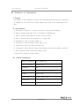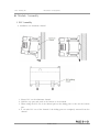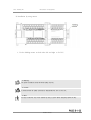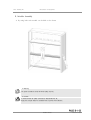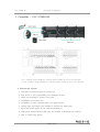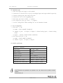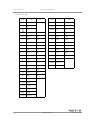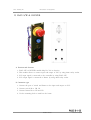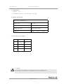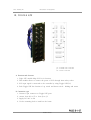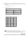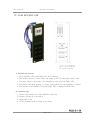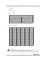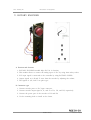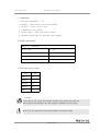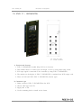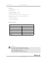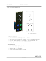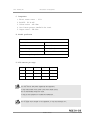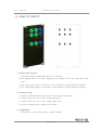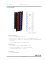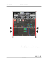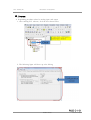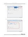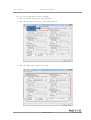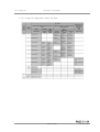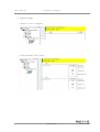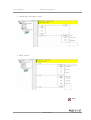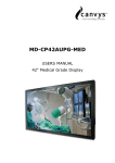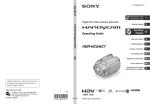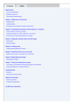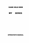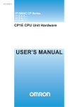
1
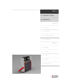
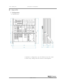
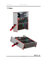
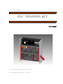
For PLC Operators PLC TRAINING KIT User Manual ◇ Please read carefully the instruction for safety before use. ◇ Please keep this user manual where is seen for users. PLC TRAINING KIT Project Name PLC TRAINING KIT Project Number DDF Customer Neo powertech [ TOTAL PAGE 5 ] Date : July 1st, 2013 Operator : DHANDY MECHA TITLE PAGE 2 / 5 DHANDY MECHA A4 (210 × 297) PLC TRAINING KIT Contents PART A. A-1. Instruction for safety A-2. Maintenance PART B. B-1. Introduction B-1-1. Summary B-1-2. Assembly of Module B-1-3. Components PART C. C-1. Appendices C-1-1. Drawings C-1-2. Pictures C-1-3. Program C-1-4. PCB Circuit TITLE PAGE 3 / 5 DHANDY MECHA A4 (210 × 297) PLC TRAINING KIT User Manual Copyright ⓒ 2013 DHANDY MECHA All user manual and pictures are reserved by law. TITLE PAGE 4 / 5 DHANDY MECHA A4 (210 × 297) PLC TRAINING KIT Operator : DHANDY MECHA Via-Email : [email protected] Phone : 031) 436-0150 Fax : 031) 436-0150 Date : July 1st 2013, The first edition ©2013 By DhandyMecha Company ◇ This user manual is including the general information for this equipment according to its purpose and the way it is used. However, the actual equipment delivered from DHANDY MECHA and contents in this manual may be different. ◇ Please contact DHANDY MECHA for incorrect contents or information needed. ◇ Please contact DHANDY MECHA when inconvenience or error on the equipment is found. ◇ Please contact DHANDY MECHAwhen extra components are in need. ◇ Please read and refer to user manual and catalog provided with the equipment and practice before use. TITLE PAGE 5 / 5 DHANDY MECHA A4 (210 × 297) PART A. A-1. Instruction for safety A-2. Maintenance PART B. B-1. Introduction B-1-1. Summary B-1-2. Assembly Process B-1-3. Components PART C. C-1. Appendices C-1-1. Drawings C-1-2. Pictures C-1-3. Program C-1-4. PCB Circuit PLC Training kit Instruction for safety Instruction for safety Please follow the instruction for safety to prevent from incident and to use in right way. Instruction for safety is distinguished by such warning and caution symbol and the following figures are their description. Please read the instruction for safety before use. Symbol of warning Electrical Danger Indicating probability of high voltage electric shock, body injury or even death if violated Warning Indicating probability of danger, body injury and even death if violated Caution Indicating probability of danger, body injury or damage on the product if violated Note Extra information and contents DHANDY MECHA A4 (210 × 297) PLC Training kit Instruction for safety Instruction for safety 1. When handling the equipment please check out surrounding there is no obstacle around the equipment. 2. Check out electrical system before powering the equipment. 3. During operation be aware of electric shock and surrounding. 4. Frequently check out equipment safety and condition to keep it in a good condition. 5. Do not use any uncertified devices except provided with product catalog and drawing. 6. Contact DHANDY MECHA if altering or remodeling equipment. 7. Use right power source so it works fine. 8. Use power outlet with its ground so it prevents from leaking electricity and electric shock. 9. Keep the equipment away from magnetic material to prevent from malfunction. 10. Keep the equipment in clean area and away from moisture atmosphere to prevent from over heat and error in the equipment. DHANDY MECHA A4 (210 × 297) PLC Training kit Instruction for safety Warnings in use 1. Do not ride over, smash, or drop off from a distance. - Caused error, damage, oil leak, or malfunction. 2. Do not place wet material around the equipment. - Caused electric shock. 3. Do not handle the electrical material or touch power plug with wet hands. - Caused electrical shock. 4. Do not cause problems that occur physical injury by inserting a part of physical body. - Caused physical injury. 5. Do not use loose power cable. - Caused electric spark and fire on. DHANDY MECHA A4 (210 × 297) PLC Training kit Instruction for safety Electrical controller related safety instruction 1. Do ont change any electrical circuit. - Caused false operation and incorrect operation. 2. Do ont intend to dis-assemble, change or reform any equipment. - Caused electric leakness, over heat, or short circuit so they could not be certified in quality assurance. 3. Do not place any equipment within moisture-surrounded place or over flood. - Caused insulation problem and low quality in use. DHANDY MECHA A4 (210 × 297) PLC Training kit Instruction for safety Electrical controller-related safety instruction 1. Do not take any maintenance work or operation except the genuine operator. - Caused false operation, body injury or electric shock. 2. When maintaining, release out charged electrical power before use. - Caused body injury or electric shock. 3. Adjust bolts and screws with valued torque. - Caused over heat and emergency in fire. 4. Do not use wet fuse when replacing the fuse. - Caused body injury or electric shock. 5. Remove tools, cable wire, bolts, and washers after installation and maintenance. - Caused short circuit or emergency in fire. 6. When maintaining, turn off the main power and saty on test mode. - Caused electric shock. 7. Use proper multi test instrument to check out if the main power is off. - Caused electric shock. 8. Do not use any longer bolts than is provided. - Caused short circuit or emergency in fire. 9. During operation Do not wipe out the surface of products with wet materials. - Caused electric shock. DHANDY MECHA A4 (210 × 297) PLC Training kit Instruction for safety Instruction for maintenance and keep 1. Customers are prohibited to remodel any product. 2. Do not dis-assemble and re-assemble stadarized products because it causes products not working properly. 3. When moving or keeping, be aware of the temperature around the equipment. 4. Maintain the room temperature and moisture surrounding where the equipment is placed, otherwise, it causes malfunction and change in appearance. 5. Check connected wire and components. Otherwise it causes error and problem in the equipment. Proper temperature 18~28℃ Proper moisture 40~60% DHANDY MECHA A4 (210 × 297) PLC Training kit Instruction for safety Disposal Instruction 1. Collect what could be re-used or not and dispose them where it is certified. 2. Contact DHANDY MECHA if willing to utilize used product, For specialized products you may contact with their company. 3. When disposal, things that cause poison problem are needed to be disposed to certified places. Contact DHANDY MECHA when willing to dispose equipment. We will help you out. [DHANDY MECHA] Via-Email : [email protected] Phone : 031) 436-0150 Fax : 031) 436-0150 DHANDY MECHA A4 (210 × 297) PLC Training kit Maintenance of Equipment ◈ Maintenance of Equipment 1. Considerations for maintenance Performance and period of maintenance are determined by several conditions that are the following. A. Operating Duration Old equipment relatively to new equipment needs to be maintained frequently. B. Importance of equipment There are significant modules and insignificant modules and the period of maintenance needs to be dependent on it. C. Surrounding conditions The life of equipment will be dependent on how good the surrounding conditions are, inside or outside, how much moisture and poisoning gas present and presence of vibration, overheat, etc. D. History of malfunction There are modules that make trouble of bad conditions, so maintenance needs to be enhanced to prevent from problems that occur over again and again. E. Overload Modules with overload frequently used bad condition around, need to be maintained in a short period. DHANDY MECHA A4 (210 × 297) PLC Training kit Maintenance of Equipment 2. List of Maintenance Follow the step below and cleaning, tightening the bolts like significant job will be also the following. Making the regular time schedule for maintenance is recommended. A. Wiring check a) Check out loose point of connection and short circuit. b) Check out if there is connection problem. c) Check out wires that disturb any moving part of equipment. B. Checking equipment a) Check out if there is vibration and bad smell. b) Check out any bolts loosing off. c) Check out if there is any error in displacement of equipment. C. Maintain of cleaning a) Please remove any disturbance or obstacle around that gets equipment in trouble. b) Check out whether indicator, lamp, or buzzer work fine or not. 3. Process A. Normal type process Picture 1 Normal type process example DHANDY MECHA A4 (210 × 297) PLC Training kit Maintenance of Equipment B. Regular inspection process No. Process Method and consideration 1. Vacuum type cleaning is recommended and be aware of level of moisture and 1 Place and environment pressure of the air used. 2. Remove dust and material before opening the cover 3. Wiping material should be chemically neutural and be careful with level of moisture. 1. Method of tightening In case of tightening bolts use right material and components with the following (1) Tighten bolts with the right torque wrench and strength. (2) Tighten the nut. 2 strength of (3) Do not tighten bolts only one side if there are more than two bolts tightening (4) Level of Torque bolts Bolt type M3 M4 M5 M6 Torque (kgf.cm) 6~8 15~20 30~40 50~65 Bolt type M8 M10 M12 M16 Torque (kgf.cm) 150~150 240~500 420~1020 1050~1300 1. Survey the function and type when exchanging parts 3 Part 2. Do not be confused of connection and do not forget to tighten bolts replacement 3. Make sure to adjust parts if necessary 4. Let skilled-one work on soldering and complicated tasks DHANDY MECHA A4 (210 × 297) PLC Training kit Maintenance of Equipment 4. Steps for Emergency case Num Problems Out of power Causes Solutions Out of power - Checking input power Less power level - Checking the function of power switch Broken fuse - Checking fuse Switch error - Checking the power of power supply Outlet connection - Checking the power outlet Failure lamp Lamp broken - Changing lamp function Lamp life time - Checking Control power Short circuit - Checking circuit Out of power - Checking function 1 2 Note Staying emergency Out of power - Changing the indicator Reference Malfunction - Checking fuse User Short circuit - Checking with other instruments manual Switch out of Out of power - Inspection for PLC and controller control Malfunction - Inspecting switch and sensor Indicator error 3 Breakdown 4 Broken sensor Broken controller Unknown noise Obstacle Inspecting the equipment with the power Disturbance completely off Equipment 5 breakdown and deformation Malfunction Equipment Inspecting the equipment with the power Reference breakdown completely off User Out of power 6 manual Strength of volt Obstacle Connection Bolt relaxation Tightening the bolt with power off discolor Overload use Adjusting the load 7 DHANDY MECHA A4 (210 × 297) PART A. A-1. Instruction for safety A-2. Maintenance PART B. B-1. Introduction B-1-1. Summary B-1-2. Assembly Process B-1-3. Components PART C. C-1. Appendices C-1-1. Drawings C-1-2. Pictures C-1-3. Program C-1-4. PCB Circuit PLC Training kit Introduction of Equipment ◈ Summary of Equipment I. Purpose The Purpose of the equipment is to gain PLC programming skill from base to advanced by utilizing this PLC practical kit within different task based on the requirements from users. II. Specifications A. Structured to function in a variety of practice in sizing and remodeling. B. Able to perform multi tasks such as calculation and digital logic. C. Able to perform with indicator, inverter, and servo driver. D. Easy to hand and keep the equipment as a single body. E. Structured for users to practice hands-on F. Structured to use 4mm banana socket type to wire G. Structured to adjust the angle customers want H. Structured to utilize different sensors and automatic devices from outside to practice I. Able to perform PWM control and analog control J. Structured to install on frame module. III. General Information Name of equipment PLC Training kit Type of oepration Manual type Controller PLC Size 480(W) ×540(H) × 180(D) Weight About 10kg Power used DC24V, NPN TYPE Temperature -10~ +70℃ Main power AC110-240V, 50/60Hz, 2A DHANDY MECHA A4 (210 × 297) PLC Training kit Introduction of Equipment ◈ Module Assembly I. PLC Assembly A. Installation on Aluminum channel 1. PInsert PLC on the aluminum channel . 2. Hold the top part and push in the bottom to be mounted. 3. When taking the PLC out of the channel pull out the sliding parts to take out the bottom part. 4. It can take PLC out of the channel if the sliding parts are completely removed from the channel DHANDY MECHA A4 (210 × 297) PLC Training kit Introduction of Equipment B. Installation by using mount 1. Use the holding mount on both sides left and right to fix PLC. Warning The power should be turned off when taking out PLC. Caution It should remove all cables connected to disassemble PLC unit or extra unit. Note It’s easy to take PLC out of the channel by using (-) screw driver and pulling down the PLC. DHANDY MECHA A4 (210 × 297) PLC Training kit Introduction of Equipment II. Module Assembly A. By using bolts each module can be held on the frame. Warning The power should be turned off when taking out PLC. Caution It should remove all cables connected to disassemble PLC kit. Apply the strength based on standard level to prevent from abrasion. DHANDY MECHA A4 (210 × 297) PLC Training kit Introduction of Equipment ◈ List of components ※ Description of warning signs Electric Danger Indicating probability of high voltage electric shock and body injury or even death if violated Warning Indicating probability of danger if violated then it causes body injury or even death Caution Indicating probability of danger if violated it causes body injury or damage on the products Note Extra information and contents DHANDY MECHA A4 (210 × 297) PLC Training kit Introduction of Equipment I. Controller - PLC (OMRON) I0, I1 : DIGITAL INPUT Module Kit, ANALOG IN/OUT Module Kit (one to one connection) Q1, Q2 : DIGITAL OUTPUT Module Kit, ANALOG IN/OUT Module Kit (one to one connection) A. Function and structure 1. Structures for different types of practical kit 2. Easy access to PLC programming tool through USB port 3. Multi port included to connect extra ports 4. Availability of RS-232C port 5. Availability of serial communication over option board 6. Analog input and output port included to perform the multi tasks 7. Input and output signal can be connected module kit 8. High speed counter function and pulse are installed to determine the location. 9. Able to install extra battery DHANDY MECHA A4 (210 × 297) PLC Training kit Introduction of Equipment B. Connection type 1. Wire PLC input and output to each module 2. Connect I0, I1 from the PLC to Q0, Q1 from digital input and output module respectively 3. Connect external ports when using extra unit 4. Connect DC 24V to PLC supplying ports 5. PLC input port (I0, I1) COM : (+) positive 6. PLC output port (Q0, Q1) COM : (-) Negative 7. Use PLC fixing blocks When installing PLC on the aluminum channel C. List of components 1. PLC unit : 1 EA a) Model : CP1E-NA20DT [OMRON] b) Number of ports : 12 Inputs, 8 Outputs, 2 channel analog input, 1 channel analog output c) Option : 1 Battery (CP1W-BAT01) [OMRON] 2. PLC Extra PLC unit : 1 EA a) Model : CP1W-20EDT [OMRON] b) Number of ports : 12 Inputs, 8 Outputs D. Module specification Electricity / Mechanic Main Power AC 100 ~ 240V Input Voltage DC 24V Electric Current 0.02A Connection type Wire connector Output type Transistor (Sink, Source), Relay Dimension (PLC Unit) 130(W) × 90(H) × 85(D) Dimension (PLC Extra Unit) 90(W) × 85(H) × 55(D) Note Detail information and specification are described in the user manual that the product company provided. www.ia.omron.co.kr DHANDY MECHA A4 (210 × 297) PLC Training kit Introduction of Equipment E. PLC I/O List PIN I0 I1 PIN Q0 Q1 + 24V NC - - - 0V NC - - FG COM 0V 0V NC - - 0 Q00 Q08 COM 24V 24V 1 Q01 Q09 0 I00 I0C 2 Q02 Q0A 1 I01 I0D 3 Q03 Q0B 2 I02 I0E 4 Q04 Q0C 3 I03 I0F 5 Q05 Q0D 4 I04 I10 6 Q06 Q0E 5 I05 I11 7 Q07 Q0F 6 I06 I12 VOUT0 VOUT0 7 I07 I13 IOUT0 IOUT0 8 I08 I14 COM COM 9 I09 I15 10 I0A I16 11 I0B I17 VIN0 VIN0 IIN0 IIN0 COM COM VIN1 VIN1 IIN1 IIN1 COM COM DHANDY MECHA A4 (210 × 297) PLC Training kit Introduction of Equipment II. EMG S/W & BUZZER A. Function and Structure 1. EMG S/W & BUZZER module help PLC kit in function 2. This module allows to connect input and output of PLC by using 4mm safety socket. 3. PLC input signal is connected to the controller by using EMG S/W 4. PLC output signal is connected to Buzzer by using 4mm safety socket B. Connection type 1. Connect the port of switch and Buzzer to the input and output on PLC 2. Connect switch S0 to H0, H1 3. Connect Buzzer B0 to H2 and H3 4. Use the mounting bolt to install on the frame DHANDY MECHA A4 (210 × 297) PLC Training kit Introduction of Equipment C. compositions 1. Buzzer : 1 EA 2. Emergency switch : 1 EA (1b, Turn-reset type) D. Module specification Electricity / Mechanism Power used DC 24V Input / Output Max. DC 24V Connection type 4mm Safety socket Dimension 50(W) × 173(H) × 105(D) E. PCB connecter pin assign PIN S0 B0 1 - H2 2 H0 H3 3 H1 - 4 - - Caution Do not apply much strength on the equipment, it may cause damage on it. DHANDY MECHA A4 (210 × 297) PLC Training kit Introduction of Equipment III. TOGGLE S/W J0 : TOGGLE S/W connection J2 : TOGGLE S/W connection P0 : DC24V connection A. Function and Structure 1. Togle S/W module helps PLC kit in function 2. This module allows to connect the power of PLC through 4mm safety socket 3. PLC input signal is connected to the controller by using Toggle S/W니다. 4. Each Toggle S/W has function of up switch and down switch : holding and return B. Connection type 1. Connect 8 pin connector to Toggle S/W ports 2. connect from S0 to S7 to from J0 to J2 3. Supply DC 24V to P0 4. Use the mounting bolt to install on the frame DHANDY MECHA A4 (210 × 297) PLC Training kit Introduction of Equipment C. Composition 1. Toggle S/W : 8 EA 2. Function : Remain(Up), Return(Down) D. Module Specification Electricity / Mechanism Power used DC 24V Input Power Max. DC 24V Connection type 4mm Safety socket Dimension 50(W) × 173(H) × 105(D) E. PCB connecter pin assign PIN J0 J1 J2 1 S0 (1,3) - S0 (2) 2 S1 (1,3) - S1 (2) 3 S2 (1,3) - S2 (2) 4 S3 (1,3) - S3 (2) 5 S4 (1,3) - S4 (2) 6 S5 (1,3) - S5 (2) 7 S6 (1,3) - S6 (2) 8 S7 (1,3) - S7 (2) Caution Do not apply much strength on the equipment, it may cause damage on it. DHANDY MECHA A4 (210 × 297) PLC Training kit Introduction of Equipment IV. SUM ROTARY S/W A0, A1 : J0, J1 connection J0, J2 : A0, A1 connection P0 : DC24V connection A. Function and Structure 1. SUM ROTARY S/W module helps PLC kit in function. 2. This module allows to connect input and output of PLC by using 4mm safely socket. 3. PLC input signal is connected to the controller by using SUM ROTARY S/W 4. Increased by one when pushing (+) button, Decreased by one when pushing (-) button. 5. The number on the module of SUM ROTARY S/W is displayed in BCD code. B. Connection type 1. Cnnect 8 pin connector to SUM ROTARY S/W ports 2. Connect A0 and A1 to J0 and J2 3. Supply 24V to P0 4. Use the mounting bolts to install on the frame DHANDY MECHA A4 (210 × 297) PLC Training kit Introduction of Equipment C. Composition 1. ROTARY S/W : 2 EA 2. Indication : 0~9 D. Module specification Electricity / Mechanism Power used DC 24V Input power Max. DC 24V Connection type 4mm safety socket Dimension 50(W) × 173(H) × 105(D) E. PCB connecter pin assign PIN A0 A1 J0 J1 J2 1 - - A0 (5) - A0 (3) 2 - - A0 (7) - A1 (3) 3 J2 (1) J2 (2) A0 (9) - - 4 - - A0 (11) - - 5 J0 (1) J0 (5) A1 (5) - - 6 - - A1 (7) - - 7 J0 (2) J0 (6) A1 (9) - - 8 - - A1 (11) - - 9 J0 (3) J0 (7) 10 - - 11 J0 (4) J0 (8) Caution Do not apply much strength on the equipment, it may cause damage on it. DHANDY MECHA A4 (210 × 297) PLC Training kit Introduction of Equipment V. ROTARY ENCODER A. Function and Structure 1. ROTARY ENCODER module helps PLC kit in function. 2. This module allows to connect the analog input of PLC by using 4mm safety socket. 3. PLC input signal is connected to the controller by using ROTARY CODER. 4. Output signals on A,B and Z come from the encoder by adjusting the volume. 5. The signals of A,B, and Z are pulse type. B. Connection type 1. Connect encoder ports to PLC input connector. 2. Connect encoder output signal A, B, and Z to Ho, H1, and H2, respectively. 3. Connect the power port of the encoder to H3 and H4. 4. Use the mounting bolts to install on the frame. DHANDY MECHA A4 (210 × 297) PLC Training kit Introduction of Equipment C. Composition 1. ROTARY ENCODER : 1 EA 2. MODEL : E30S-4-360-3-N-24 [AUTONICS] 3. OUTPUT : 3 ports (A, B, Z port) 4. 1 360pulse per one rotation 5. Control output : NPN open collector output 6. Aluminum handle knob for indicating values applied D. Module Specification Electricity / Mechanism Power used DC 24V Input power Max. DC 24V Connection type 4mm Safety socket Dimension 50(W) × 173(H) × 105(D) E. PCB connecter pin assign PIN E0 Black H0 White H1 Orange H2 Brown H3 Blue H4 Caution Please read the user manual and description especially wiring related tasks before use. Poor attention and mishandling may cause damage or breakdown for the products Note Refer to the user manual that offers detail description and control method. DHANDY MECHA A4 (210 × 297) PLC Training kit Introduction of Equipment VI. FND (7 - SEGMENTS) T0 : PNP, NPN setup P0 : DC24V connection A. Function and Structure 1. FND (7-SEGMENTS) module helps PLC kit in function. 2. This module allows to connect iput and output of PLC by using 4mm safety socket. 3. PLC input signal is connected to the controller by using FND (7-SEGMENTS). 4. The number on the display of FND (7-SEGMENTS) is translated into BCD output code. 5. There are PNP and NPN FND (7-SEGMENTS) function types. B. Connection type 1. Solder connector FND (7-SEGMENTS)on the PCB. 2. Choose NPN type from T0. 3. Supply 24V to P0. 4. Use the mounting bolts to install on the frame. DHANDY MECHA A4 (210 × 297) PLC Training kit Introduction of Equipment C. Composition 1. FND (7-Segment) : 1 EA 2. 2 RED LED 3. Size of the segment : 14.2mm 4. Alphabetical indicator : A~F 5. Function of NPN and PNP circuit by using jumper pin, 6. Protection circuit for Over current and reverse current. 7. Range of DC power a) High : DC 1.2V~30V b) Low : DC 0V~0.6V D. Module Specification Electricity / Mechanism Power used DC 24V Electric current 20mA 이하 Response frequency 최대 5KHz Input resistor 20K Ohm Connection type 4mm safety socket Dimension 50(W) × 173(H) × 60(D) Danger Use only the DC 24V power supplied by the equipment. It may make trouble if the power comes from outside source. Do not intentionally change the circuit. It may get the equipment in trouble and malfunction. DHANDY MECHA A4 (210 × 297) PLC Training kit Introduction of Equipment VII. VOLT GENERATOR VO, V1 : J0, J1 Connection P0 : DC24V Connection A. Function and Structure 1. VOLT GENERATOR module helps PLC kit in function 2. This module allows to connect iput and output of PLC by using 4mm safety socket. 3. PLC input signal is connected to the controller by using SUM ROTARY S/W 4. Voltage depends on the volume of the VOLT GENERATOR. B. Connection type 1. Solder VOLT GENERATOR on the PCB. 2. Connect V0 and V1 to J0 and J2. 3. Supply DC 24V to 2 pin connector. 4. Use the mounting bolt to install on the frame. DHANDY MECHA A4 (210 × 297) PLC Training kit Introduction of Equipment C. Composition 1. Electric current creator : 2 EA 2. RANGE : DC 0~10V 3. Volume resistor : 10k Ohm 4. Over Current protector installed in the circuit. 5. Output resistor : 470 Ohm D. Module specification Electricity / Mechanism Power used DC 24V RANGE DC 0~10V Connection type 4mm 안전 소켓 Dimension 50(W) × 173(H) × 105(D) Able to change the specification of the module E. PCB connecter pin assign PIN V0 V1 J0 J1 1 J0 (1) J1 (1) V0 (1) V1 (1) 2 J0 (2) J1 (2) V0 (2) V1 (2) 3 J0 (3) J1 (3) V0 (3) V1 (3) Danger Use only the DC 24V power supplied by the equipment. It may make trouble if the power comes from outside source. Do not intentionally change the circuit. It may get the equipment in trouble and malfunction. . Caution Do not apply much strength on the equipment, it may cause damage on it. DHANDY MECHA A4 (210 × 297) PLC Training kit Introduction of Equipment VIII. VOLT & AMPERE METER A0 : H0, H1 socket connection A1 : H2, H3 socket connection A. Function and Structure 1. VOLT & AMPERE METER module helps PLC kit in function. 2. This module allows to connect the power of PLC through 4mm safety socket. 3. PLC analog input signal is controlled by VOLT & AMPERE METER. 4. The variable voltage value is indicated on VOLT METER in number and the variable Ampere value is indicated on AMPERE METER in number. B. Connection type 1. Solder VOLT & AMPERE METER connector on the PCB. 2. Connect A0 and A1 connectors to H0, H1, H2, and H3. 3. Supply DC 24V to 2 pin connector. 4. Use the mounting bolt to install on the frame. DHANDY MECHA A4 (210 × 297) PLC Training kit Introduction of Equipment C. Composition 1. Current indicator: 1 channel, 1 channel of electric current indicator (2 total) 2. Model : M4N-DV-13, M4N-DA-13 [AUTONICS] 3. Number of digit : 4digit (7segment RED LED) 4. Input power : 19.99V 5. Range of tolerance : ±0.2% 6. Period of sample : 300ms 7. Function type : Binomial type 8. Period : 2.5 cycle/min D. Module specification Electricity / Mechanism Power used DC 24V Voltage Range : 0~10V Current Range : 4~20mA Connection type 4mm safety socket Dimension 50(W) × 173(H) × 105(D) E. PCB connecter pin assign PIN A0 A1 1 24V 24V 2 0V 0V 3 - - 4 - - 5 - - 6 - - 7 - - 8 - - 9 H0 H2 10 H1 H3 DHANDY MECHA A4 (210 × 297) PLC Training kit Introduction of Equipment IX. MOTOR & SENSOR M0 : J0 connector SR0, SR1 : J0, J1, J2 connection P0 : J0 connection A. 구조와 기능 1. MOTOR & SENSOR module helps PLC kit in function. 2. This module allows to connect the power of PLC through 4mm safety socket. 3. PLC input signal is connected to the controller by using MOTOR & SENSOR. 4. PLC output signal is connected into MOTOR & SENSOR by using 4mm safety socket. 5. Motor is controlled by producing pulse from the pulse generator PWM. B. Connection Type 1. Connect 8 pin connector to MOTOR & SENSOR module connector. 2. Connect M0 port to J0 connector. 3. Connect SR0 and SR1 ports to J0, J1, and J2 connector. 4. Supply DC 24V to P0 through J0 connector. 5. Use the mounting bolt to install on the frame. DHANDY MECHA A4 (210 × 297) PLC Training kit Introduction of Equipment C. Compositions 1. DC gear motor : 1 EA a) Model : [GGM] b) Speed reducer installed inside (1/30) c) Period : about 190rpm d) Output torque : 0.39kgf>cm 2. 2 Micro photo sensor a) Model: EE-SX912-R, EE-SX913-R [OMRON] b) Allowed Current: 100mA Max c) Response frequency : 1kHz min D. Module Specification Electricity / Mechanism Power used DC 24V Current Below 15mA ~ 0.3A Connection type 4mm safety socket Dimension 50(W) × 173(H) × 105(D) DHANDY MECHA A4 (210 × 297) PLC Training kit Introduction of Equipment E. PCB connecter pin assign PIN J0 J1 J2 M0 PIN SR0 SR1 1 - SR0 (Brn) SR1 (Brn) J0 (2) Black J0 (3) J0 (7) 2 M0 (2) SR0 (Blu) SR1 (Blu) J0 (6) Brown J1 (1) J1 (2) 3 SR0 (Blk) Blue J2 (1) J2 (2) 4 P0 (⊕) 5 - 6 M0 (1) 7 SR1 (Blk) 8 P0 (⊖) Danger Use only the DC 24V power supplied by the equipment. It may make trouble if the power comes from outside source. 회Do not intentionally change the circuit. It may get the equipment in trouble and malfunction. Caution 1. Check out if there is any disturbance around the moving parts. 2. Check out if there is any disturbance around the sensors 3. Frequently check out the function of sensors. Note Refer to the user manual that offers detail description and control method. DHANDY MECHA A4 (210 × 297) PLC Training kit Introduction of Equipment X. ANALOG IN/OUT A. Function and Structure 1. ANALOG IN/OUT module helps PLC kit in function. 2. This module allows to connect analog input and output of PLC by using 4mm safety socket. 3. PLC analog input signal is connected to the controller by using ANALOG IN/OUT 4. PLC analog output signal is connected to the controller by using ANALOG IN/OUT. B. Connection Type 1. Connect ANALOG IN/OUT ports to PLC analog input and output. 2. Connect from A0 to A5 to PLC analog input ports. 3. Connect from A6 to A8 to PLC analog output ports. 4. Use the mounting bolts to install on the frame. C. Compositions 1. 2 channels for current and voltage, 1 output channel. DHANDY MECHA A4 (210 × 297) PLC Training kit Introduction of Equipment D. Module Specification Electricity / Michanism Power used DC 24V Connection type 4mm Safety socket Dimensions 86(W) × 173(H) × 105(D) E. PCB connecter pin assign PIN H 0 AD00(V) 1 AD00(I) 2 COM 3 AD01(V) 4 AD01(I) 5 COM 6 DA00(V) 7 DA00(I) 8 COM DHANDY MECHA A4 (210 × 297) PLC Training kit Introduction of Equipment XI. DC HUB MP0, MP1 : MAIN DC24V P0~P15 : SUB DC24V A. Function and Structure 1. DC HUB module helps PLC kit in function. 2. This module allows to supply DC 24V to PLC kit by using 4mm safety socket. 3. DC24V power will be supplied to each different modules through DC HUB by using 4mm safety socket. 4. Red sockets supply DC 24V and 0V from blue sockets. B. Connection type 1. Supply DC 24V to MP0 and MP1 through 2 pin connector. 2. Pin from P0 to P15 supply DC 24V to each different modules. 3. Use the mounting bolts to install on the frame. C. Compositions 1. 8 power distributing ports. DHANDY MECHA A4 (210 × 297) PLC Training kit Introduction of Equipment D. Module Specification Electricity / Mechanism Power used DC 24V Connector type 4mm Safety socket Dimension 50(W) × 173(H) × 105(D) Danger Use only the DC 24V power supplied by the equipment. It may make trouble if the power comes from outside source. Do not intentionally change the circuit. It may get the equipment in trouble and malfunction. Danger Do not use loose or damaged connector Electric shock or in case of fire. DHANDY MECHA A4 (210 × 297) PLC Training kit Introduction of Equipment XII. DIGITAL INPUT 24P (NPN) C0, C1 : PLC Input connection T0, T1 : PNP, NPN set up P0, P1 : DC24V connection A. Function and Structure 1. DIGITAL INPUT 24P module helps PLC kit in function. 2. This module allows to connect to the power of the input of PLC by using 4mm safety socket. 3. PLC input signal is onnected to the controller by using DIGITAL INPUT 24P module. 4. PLC ON/OFF sign is known by the LED of DIGITAL INPUT 24P module. B. Connection Type 1. Connect DIGITAL INPUT 24P port to PLC input ports by using 20 pin connector 2. Choose NPN type of TO and T1. 3. Supply DC 24V to P0 and P1 by using 2 pin connector. 4. Use the mounting bolts to install on the frame. DHANDY MECHA A4 (210 × 297) PLC Training kit Introduction of Equipment C. Composition 1. Input : 24 points 2. Individual status indicating LED installed inside. a) Color : Green D. Module Specification Electricity / Mechanism Power used DC 24V Input current Max. DC 24V Connection type 4mm Safety socket Dimension 86(W) × 173(H) × 105(D) E. PCB connecter pin assign PLC MAIN unit PLC extra unit PIN C0 PIN C0 PIN C1 PIN C1 0 I00 8 I08 0 I04 8 - 1 I01 9 I09 1 I05 9 - 2 I02 10 I10 2 I06 10 - 3 I03 11 I11 3 I07 11 - 4 I04 12 4 I08 12 - 5 I05 13 5 I09 13 - 6 I06 14 6 I10 14 - 7 I07 15 7 I11 15 - 16 24V 17 24V 16 24V 17 0V 18 0V 19 0V 18 24V 19 0V I00 (extra) I01 (extra) I02 (extra) I03 (extra) Danger Do not intentionally change the circuit It causes malfunction and error in function. DHANDY MECHA A4 (210 × 297) PLC Training kit Introduction of Equipment XIII. DIGITAL OUTPUT 16P (NPN) C0 : PLC input connection T0 : PNP, NPN setup P0 : DC24V connection A. Function and Structure 1. DIGITAL OUTPUT 16P module helps PLC kit in function. 2. This module allows to connect to the output power of PLC. 3. PLC output signal is connected to the controller by using DIGITAL OUTPUT 16P module. 4. PLC ON/OFF sign is known by the LED of DIGITAL INPUT 16P module. B. Connection type 1. Connect DIGITAL INPUT 16P port to PLC input ports by using 20 pin connector 2. Choose NPN type of TO 3. Supply DC 24V to P0 and P1 by using 2 pin connector. 4. Use the mounting bolts to install on the frame. DHANDY MECHA A4 (210 × 297) PLC Training kit Introduction of Equipment C. Composition 1. Output : 16points 2. Individual status indicating LED installed inside a) Color : RED D. Module Specification Electricity / Mechanism Power used DC 24V Output power Max. DC 24V Connection type 4mm Safety socket Dimension 86(W) × 173(H) × 105(D) E. PCB connecter pin assign PLC MAIN unit PLC extra unit PIN C0 PIN C0 0 O00 8 O00 1 O01 9 O01 2 O02 10 O02 3 O03 11 O03 4 O04 12 O04 5 O05 13 O05 6 O06 14 O06 7 O07 15 O07 16 24V 17 24V 18 0V 19 0V Danger Do not intentionally change the circuit It causes malfunction and error in function. DHANDY MECHA A4 (210 × 297) PLC Training kit Introduction of Equipment XIV. POWER SUPPLY F0 : Connection to the main power ports L0 : Connection to DC 24V S0 : MAIN power connection A. Function and Structure 1. POWER SUPPLY module helps PLC kit in function. 2. This module supplies all devices used with PLC kit by using 4mm safety socket. 3. ON/OFF for Supplying DC24V is checked by LED in the power supply. 4. A fuse is installed to protect modules in the power supply. B. Connection type 1. Connect Power supply module ports to the PCB of switches , fuses, and LEDs. 2. AC110V~240V is supplied by the switch to POWER SUPPLY module. 3. DC 24V converted from the Power supply through the fuse and LED is supplied Ho, H1, H2, and H3. 4. Use the mounting bolts to install on the frame. DHANDY MECHA A4 (210 × 297) PLC Training kit Introduction of Equipment C. Composition 1. Power ON/OFF status lamp installed inside a) Color : RED 2. Fuse for Over current installed inside a) AC110~220V fuse : 1 EA, (1) Capacity : 2A b) C24V fuse : 1 EA (1) Capacity : 3A 3. DC24V ON/OFF status LED installed inside a) Color : Green D. Module Specification Electricity / Mechanism Power used DC 24V, max 3A AC 110~220V (Free volt) Input power 50 / 60Hz Connection type 4mm Safety socket Dimension 96(W) × 173(H) × 105(D) E. PCB connecter pin assign PIN MP0 S0 F0 L0 1 F0 (2) MP0 (4) L0 (2) H0, H1 2 H2, H3 N (AC) MP0 (1) F0 (1) L (AC) - - 3 4 S0 (1) - - - 5 L (AC) - - - Caution Do not apply much strength on the equipment, it may cause damage on it. Note When the lamp is off, check the fuse first and replace it if necessary. DHANDY MECHA A4 (210 × 297) PLC Training kit Introduction of Equipment XV. List of components A. Controller - PLC (OMRON) 1. PLC unit : 12 inputs, 8 outputs, 2 channel analog input, 1 channel analog output [OMRON] CP1E-NA20DT-D 2. PLC expansion unit : 12 inputs, 8 outputs, [OMRON] CP1W-20EDT 3. Battery : [OMRON] CP1W-BAT01 (Option) B. EMG S/W & BUZZER 1. Buzzer : 1 EA 2. Emergency switch : 1b, Turn-reset type C. TOGGLE S/W 1. Toggle switch: 8 EA 2. Function : Remain(up), Return(down) D. SUM ROTARY S/W 1. 0~9 Indication E. ROTARY ENCODER 1. Output : 3 types 2. Output : NPN Open collector 3. Power : DC24V F. FND (7 - SEGMENTS) 1. RED LED, binary type 2. Indication of number : 0~9 3. Indication of alphabet : A~F 4. DOT indication included G. VOLT GENERATOR 1. Power generator : 2EA (0~10V) DHANDY MECHA A4 (210 × 297) PLC Training kit Introduction of Equipment H. VOLT & AMPERE METER 1. Each volt and current indicator (Total 2) a) Number of digit : 4digit (7segment Red LED) b) Input range : 19.99V c) Tolerance : ±0.,2% d) Sampling period : 300ms e) Fuction : Binary type f) Frequency : 2.5 cycle/min I. MOTOR & SENSOR 1. Motor : DC gear motor, 1EA a) Reducer (1/30) b) Output cycle: about 190RPM c) Current : about 0.3A (free resistor) d) Output torque : 0.39kgf.cm 2. Sensors : Micro photo sensor, 2EA a) Allowed output current : 100mA Max b) Frequency : 1kHz min J. ANALOG IN/OUT 1. 2 current and voltage input channels, 1 output channel K. DC HUB 1. Power distributor module 2. DC24V power distributor L. DIGITAL INPUT 24P (NPN) 1. Input : 24 points 2. Status indicator LED installed inside a) Color : Green M. DIGITAL OUTPUT 12P (NPN) 1. Output : 16points 2. Status indicator LED installed inside a) Color : RED DHANDY MECHA A4 (210 × 297) PLC Training kit Introduction of Equipment N. POWER SUPPLY 1. Input power : 88~264VAC (100~240VAC recommended) 2. Input frequency : 50~60Hz 3. Power ON/OFF status indicator lamp installed 4. Overload fuse installed 5. DC24V ON/OFF status LED installed O. Power Cable 2m: 1ea P. PLC connection Cable : 1set Q. 4mm safety socket Cable : 1set 1. Red 250mm : 5ea 2. Red 500mm : 4ea 3. Red 1000mm :1ea 4. Black 250mm : 15ea 5. Black 500mm : 20ea 6. Black 1000mm :2ea 7. Blue 250mm : 5ea 8. Blue 500mm : 4ea 9. Blue 1000mm : 1ea R. Operation Manual : 1 set S. PLC Application program CD : 1 set (OPTION, Customized ) T. Tools and devices for Maintenance : 1set (one single set) DHANDY MECHA A4 (210 × 297) PART A. A-1. Instruction for safety A-2. Maintenance PART B. B-1. Introduction B-1-1. Summary B-1-2. Assembly Process B-1-3. Components PART C. C-1. Appendices C-1-1. Drawings C-1-2. Pictures C-1-3. Program C-1-4. PCB Circuit PLC Training kit Introduction of Equipment ◈ Appendix I. Configuration A. External view ※ Reference configuration may be different from the actual. ※ There may change with the reason for development. DHANDY MECHA A4 (210 × 297) PLC Training kit Introduction of Equipment Ⅱ. Pictures DHANDY MECHA A4 (210 × 297) PLC Training kit Introduction of Equipment ※ Different quality from the actual one. ※ There may change with the reason for development. DHANDY MECHA A4 (210 × 297) PLC Training kit Introduction of Equipment Ⅲ. Program A. Programing procedure related to analog input and output 1. After running PLC software, click the box shown below. 2. The following figure will show up after clicking. DHANDY MECHA A4 (210 × 297) PLC Training kit Introduction of Equipment 3. Click AD/DA on the top of the right hand side in the following figure 4. Check the box and choose the range of analog input and output source. DHANDY MECHA A4 (210 × 297) PLC Training kit Introduction of Equipment B. Set up for the high speed counter controller 1. Click set-up like the previous step performed. 2. Click built-in input on the top of the right hand side 3. Check the high speed counter to be used. DHANDY MECHA A4 (210 × 297) PLC Training kit Introduction of Equipment 4. List of inputs for high speed counter and pulse. DHANDY MECHA A4 (210 × 297) PLC Training kit Introduction of Equipment C. Program example 1. Buzzer in case of emergency 2. SUM ROTARY S/W Control DHANDY MECHA A4 (210 × 297) PLC Training kit Introduction of Equipment 3. FND (7-SEGMENT) Control 4. Encoder Control DHANDY MECHA A4 (210 × 297) PLC Training kit Introduction of Equipment 5. Analog input and output control 6. PWM Control END DHANDY MECHA A4 (210 × 297)