1
engineering
mannesmann
Rexroth
DIAX 04
AHS-03VRS
HDS
ANALOG
DANGE
High V
oltage.
Danger of electrical shock.
Do not touch
for
electrical
connec tions
5 minutes after switching power
Read and follow "Safety
Instructions for Electrical Drives"
manual,
DOK-GENERL-DRIVE******-SVS...
DIAX04
Drive With Main Spindle Function,
Analog- and Parallelinterface
Functional Description: AHS 03VRS
DOK-DIAX04-AHS-03VRS**-FK01-EN-P
281584
Indramat
About this documentation
Titel
Type of Documentation
Documentation Type
Internal Filing Notation
DIAX04 AHS-03VRS
DIAX04 Drive With Main Spindle Function, Analog- and Parallelinterface
Functional Description
DOK-DIAX04-AHS-03VRS**-FKB1-EN-P
• Schuber 64-03V-EN
• Based on: ASE 03V
• 120-0800-B319-01
What is the purpose of this
documentation?
The following documentation describes the functions of the firmware
FWA-DIAX04-AHS-03VRS.
This documentation serves trained maintenance personnel:
• for Description of all functional features
• for parameterization of the drive controller
• for data security of the drive parameter
• for error diagnosis and error removal
Course of modifications
Copyright
Document identification of
previous and present output
Release
Date
Remarks
DOK-DIAX04-AHS-03VRS**-FK01-EN-P
08.98
First edition
INDRAMAT GmbH, 1999
Transmission as well as reproduction of this documentation, commercial
use or communication of its contents will not be permitted without
expressed written permission. Violation of these stipulations will require
compensation. All rights reserved for the issuance of the patent or
registered design. (DIN 34-1)
Validity
Published by
All rights are reserved with respect to the content of this documentation
and the availability of the product.
INDRAMAT GmbH • Bgm.-Dr.-Nebel-Str. 2 • D-97816 Lohr a. Main
Telephone 09352/40-0 • Tx 689421 • Fax 09352/40-4885
Dept. ECD (Fle/JR)
Note
This Documentation is printed on chlorine-free bleached paper.
DOK-DIAX04-AHS-03VRS**-FK01-EN-P
DIAX04 AHS-03VRS
Contents I
Contents
1 System Overview
1-1
1.1 Range of Uses ..................................................................................................................................... 1-1
1.2 DIAX04 - a Drive Family....................................................................................................................... 1-1
1.3 Drive Controllers .................................................................................................................................. 1-2
1.4 Function Overview: FWA-DIAX04-ASE-02VRS-MS ............................................................................ 1-3
Command Communications Interfaces......................................................................................... 1-3
Possible Operating Modes ............................................................................................................ 1-3
Supported motor types .................................................................................................................. 1-3
Supported Measuring Systems ..................................................................................................... 1-3
General Functions......................................................................................................................... 1-4
Main Spindle Function................................................................................................................... 1-5
2 Safety Instructions for Electrical Drives
2-1
2.1 Introduction .......................................................................................................................................... 2-1
2.2 Hazards by improper use ..................................................................................................................... 2-2
2.3 General ................................................................................................................................................ 2-3
2.4 Protection against contact with electrical parts and not grounded enclosures .................................... 2-4
2.5 Protection by protective low voltage (PELV) against electrical shock............................................ 2-5
2.6 Protection against dangerous movements........................................................................................... 2-6
2.7 Protection against magnetic and electromagnetic fields during operations and mounting .................. 2-7
2.8 Protection against contact with hot parts ............................................................................................. 2-8
2.9 Protection during handling and installation .......................................................................................... 2-8
2.10 Battery safety ..................................................................................................................................... 2-9
3 General Instructions for Installation
3-1
3.1 Definition of Terms, Introduction .......................................................................................................... 3-1
Parameter ..................................................................................................................................... 3-1
Data Storage ................................................................................................................................. 3-2
Commands.................................................................................................................................... 3-5
Operating Modes........................................................................................................................... 3-7
Warnings ....................................................................................................................................... 3-8
Error .............................................................................................................................................. 3-8
IDN List of Parameters.................................................................................................................. 3-9
3.2 Parametrization Mode - Operating Mode ........................................................................................... 3-11
Checks in the Transition Commands .......................................................................................... 3-11
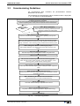
3.3 Commissioning Guidelines ................................................................................................................ 3-15
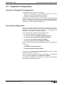
3.4 Diagnostic Configurations .................................................................................................................. 3-19
Overview of Diagnostic Configurations ....................................................................................... 3-19
Drive-Internal Diagnostics ........................................................................................................... 3-19
DOK-DIAX04-AHS-03VRS**-FK01-EN-P
II Contents
DIAX04 AHS-03VRS
Diagnostic Message Composition............................................................................................... 3-20
Collection of Status ..................................................................................................................... 3-22
3.5 Language Selection ........................................................................................................................... 3-25
4 Command Communications with Analog Interface
4-1
4.1 Overview .............................................................................................................................................. 4-1
4.2 Pertinent Parameters ........................................................................................................................... 4-1
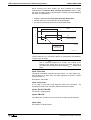
4.3 How it works......................................................................................................................................... 4-1
Digital inputs.................................................................................................................................. 4-1
Digital outputs................................................................................................................................ 4-3
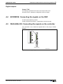
4.4 ECODRIVE: Connecting the signals on the DKC ................................................................................ 4-3
4.5 DIAX-ANALOG: Connecting the signals on the controller ................................................................... 4-3
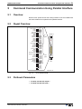
5 Command Communication Using Parallel Interface
5-1
5.1 Overview .............................................................................................................................................. 5-1
5.2 Signal Overview ................................................................................................................................... 5-1
5.3 Pertinent Parameters ........................................................................................................................... 5-1
5.4 How it works......................................................................................................................................... 5-2
Inputs............................................................................................................................................. 5-2
Outputs.......................................................................................................................................... 5-3
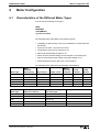
6 Motor Configuration
6-1
6.1 Characteristics of the Different Motor Types........................................................................................ 6-1
Motor Feedback-Data Memory ..................................................................................................... 6-2
Synchronous-Asynchronous ......................................................................................................... 6-2
Temperature Monitoring................................................................................................................ 6-2
Load Default Feature .................................................................................................................... 6-3
6.2 Setting the Motor Type......................................................................................................................... 6-3
Automatic Setting of the Motor Type for Motors with Feedback Memory ..................................... 6-3
Setting of the Motor Type through P-0-4014, Motor Type............................................................. 6-4
6.3 Asynchronous Motors .......................................................................................................................... 6-4
Basics for the Asynchronous Motor .............................................................................................. 6-5
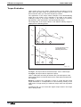
Torque Evaluation ......................................................................................................................... 6-6
User-defined Settings for the Asynchronous Motor ...................................................................... 6-7
6.4 Synchronous Motors ............................................................................................................................ 6-9
Determining the commutation offset ........................................................................................... 6-10
Field Weakening for Synchronous Motors .................................................................................. 6-12
6.5 Motor Holding Brake .......................................................................................................................... 6-12
Setting the Motor Brake Type...................................................................................................... 6-13
Setting the Motor Brake Integral Action Time ............................................................................. 6-13
Setting the Motor Brake Current ................................................................................................. 6-14
Connecting the Motor Holding Brake .......................................................................................... 6-14
7 Operating Modes
7-1
7.1 Setting Operating Mode Parameters ................................................................................................... 7-1
7.2 Programming / Detecting the Activated Operating Mode..................................................................... 7-1
DOK-DIAX04-AHS-03VRS**-FK01-EN-P
DIAX04 AHS-03VRS
Contents III
7.3 Operating Mode: Torque Control ......................................................................................................... 7-1
Pertinent Parameters .................................................................................................................... 7-2
Torque Control .............................................................................................................................. 7-2
Diagnostic Messages .................................................................................................................... 7-2
Torque Control with Analog Command Communications ............................................................. 7-3
7.4 Mode: Velocity Control ......................................................................................................................... 7-3
Pertinent Parameters .................................................................................................................... 7-3
Velocity Control with Analog Command Communications ............................................................ 7-6
Diagnostic Messages .................................................................................................................... 7-6
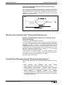
7.5 Mode: Drive Internal Interpolation ........................................................................................................ 7-6
Function principle: Drive Internal Interpolation .............................................................................. 7-7
Monitoring in mode: "Drive-internal interpolation" ......................................................................... 7-7
Status messages during operating mode "Drive-internal interpolation" ........................................ 7-8
7.6 Mode: Relative drive-internal interpolation........................................................................................... 7-9
Pertinent Parameters .................................................................................................................. 7-10
Function principle: Relative drive-internal interpolation............................................................... 7-10
Diagnostic Messages .................................................................................................................. 7-11
Status messages during operating mode "Relative drive-internal interpolation"......................... 7-11
8 Basic Drive Functions
8-1
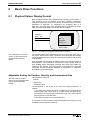
8.1 Physical Values Display Format........................................................................................................... 8-1
Adjustable Scaling for Position, Velocity, and Acceleration Data.................................................. 8-1
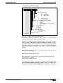
Display Format of Position Data.................................................................................................... 8-2
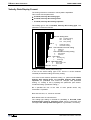
Velocity Data Display Format ........................................................................................................ 8-4
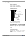
Acceleration Data Display Format................................................................................................. 8-5
Command Polarities and Actual Value Polarities.......................................................................... 8-6
Mechanical Transmission Elements ............................................................................................. 8-7
Modulo Feature ............................................................................................................................. 8-8
8.2 Setting the Measurement System...................................................................................................... 8-10
Limiting Conditions for Encoder Evaluation ................................................................................ 8-12
Motor Encoder............................................................................................................................. 8-12
Optional encoder ......................................................................................................................... 8-15
Actual Feedback Values of Non-Absolute Measurement Systems After Initialization ................ 8-21
Drive-internal format of position data .......................................................................................... 8-21
8.3 Other Settings for Absolute Measurement Systems .......................................................................... 8-25
Encoder types and relevant interfaces ........................................................................................ 8-25
Absolute encoder range and absolute encoder evaluation ......................................................... 8-25
Absolute Encoder Monitoring ...................................................................................................... 8-26
Moduleo Analysis of Absolute Measurement Systems ............................................................... 8-27
Actual Feedback Values of Absolute Measurement Systems After Initialization ........................ 8-28
8.4 Drive Limitations................................................................................................................................. 8-28
Current Limit................................................................................................................................ 8-28
Torque/Force Limiting ................................................................................................................. 8-32
Switchable torque limits............................................................................................................... 8-33
Limiting Velocity .......................................................................................................................... 8-34
8.5 Drive Error Reaction........................................................................................................................... 8-37
Power off on error ....................................................................................................................... 8-43
DOK-DIAX04-AHS-03VRS**-FK01-EN-P
IV Contents
DIAX04 AHS-03VRS
NC Response in Error Situation .................................................................................................. 8-45
Emergency stop feature .............................................................................................................. 8-46
8.6 Control Loop Settings......................................................................................................................... 8-48
General Information for Control Loop Settings............................................................................ 8-48
Load Default ................................................................................................................................ 8-50
Setting the Current Controller...................................................................................................... 8-51
Setting the Velocity Controller ..................................................................................................... 8-52
Velocity Control Loop Monitoring ................................................................................................ 8-56
Setting the position controller ...................................................................................................... 8-57
Position Control Loop Monitoring ................................................................................................ 8-58
Setting the Velocity Mix Factor.................................................................................................... 8-60
8.7 Drive Halt ........................................................................................................................................... 8-61
The Functional Principle of Drive Halt......................................................................................... 8-62
Connecting the drive halt input.................................................................................................... 8-63
8.8 Parameter Block Switching ................................................................................................................ 8-63
Overview ..................................................................................................................................... 8-63
Pertinent Parameters .................................................................................................................. 8-64
How Parameter Block Switching Works...................................................................................... 8-64
Switchable Parameters ............................................................................................................... 8-64
Commissioning Parameter Block Switching ............................................................................... 8-65
Diagnostics Messages ................................................................................................................ 8-66
8.9 Drive-Controlled Homing.................................................................................................................... 8-66
Pertinent Parameter .................................................................................................................... 8-66
Setting the referencing parameters............................................................................................. 8-67
Overview of the Type and Allocation of Reference Marks of Non-Absolute Measuring Systems8-68
Functional Principle of Drive-Controlled Referencing in Non-Absolute Measuring Systems ...... 8-69
Functional Principle of Drive-Guided Referencing with Absolute Measuring Systems ............... 8-69
Sequence control "Drive-Controlled Homing" ............................................................................. 8-70
Commissioning with Evaluation of reference marker or home switch edge ............................... 8-72
What the User should do with "Drive-guided Referencing"......................................................... 8-75
Possible Error Messages During "Drive-Controlled Homing"...................................................... 8-75
Connection of the Home switch .................................................................................................. 8-76
8.10 Set Absolute Measuring ................................................................................................................... 8-76
Function Principle Set Absolute Measuring................................................................................. 8-77
Diagnostic messages .................................................................................................................. 8-79
9 Optional Drive Functions
9-1
9.1 Configurable Signal Status Word......................................................................................................... 9-1
Pertinent Parameters .................................................................................................................... 9-1
Configuration of the Signal Status Word....................................................................................... 9-1
Diagnostic / Error Messages ......................................................................................................... 9-2
9.2 Analog Output ...................................................................................................................................... 9-2
Possible output functions .............................................................................................................. 9-3
Direct analog outputs .................................................................................................................... 9-3
Analog output of existing parameters............................................................................................ 9-3
Outputting pre-set signals ............................................................................................................. 9-4
Bit and byte outputs of the data memory....................................................................................... 9-5
DOK-DIAX04-AHS-03VRS**-FK01-EN-P
DIAX04 AHS-03VRS
Contents V
Terminal assignment - analog output............................................................................................ 9-6
9.3 Analog Inputs ....................................................................................................................................... 9-6
Functional principle of the analog inputs ....................................................................................... 9-7
Transition of Analog Input for C-Axis Mode .................................................................................. 9-8
Analog Inputs - Connection ......................................................................................................... 9-10
9.4 Digital Input/Output ............................................................................................................................ 9-11
Digital I/O Functional Principle .................................................................................................... 9-12
Allocating ID Number - Parallel I/O ............................................................................................. 9-14
9.5 Oscilloscope Feature ......................................................................................................................... 9-17
Main Functions of the Oscilloscope Feature ............................................................................... 9-17
Parameterizing the Oscilloscope Feature ................................................................................... 9-18
9.6 Command - detect marker position.................................................................................................... 9-24
Functional principle of command detect marker position............................................................ 9-24
9.7 Command Parking Axis ..................................................................................................................... 9-25
The functional principle of the command parking axis ................................................................ 9-25
9.8 Encoder Emulation............................................................................................................................. 9-25
Pertinent Parameters .................................................................................................................. 9-26
Activating Encoder Emulation ..................................................................................................... 9-26
Functional principle: Incremental Encoder Emulation ................................................................. 9-26
Diagnostic Messages with Incremental Encoder Emulation ....................................................... 9-28
Functional Principle: Absolute Encoder Emulation ..................................................................... 9-29
9.9 Spindle Positioning............................................................................................................................. 9-30
Pertinent Parameters .................................................................................................................. 9-31
Functional Principle of Command Spindle Positioning................................................................ 9-31
Starting Up Spindle Positioning................................................................................................... 9-35
Diagnostic Messages .................................................................................................................. 9-38
Electrical Connection of the Reference Switch ........................................................................... 9-40
9.10 Drive-controlled oscillation ............................................................................................................... 9-40
Overview ..................................................................................................................................... 9-40
Pertinent Parameter .................................................................................................................... 9-40
Functional Principle ..................................................................................................................... 9-41
Commissioning............................................................................................................................ 9-41
Diagnostics Messages ................................................................................................................ 9-42
9.11 Automatic Start/Delta Switch............................................................................................................ 9-43
Overview ..................................................................................................................................... 9-43
Pertinent Parameter .................................................................................................................... 9-44
How the Star/Delta Switch works ................................................................................................ 9-44
Projecting Star/Delta Switching ................................................................................................... 9-45
Commissioning Star/Delta Switching .......................................................................................... 9-46
Diagnostic Messages .................................................................................................................. 9-47
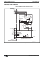
9.12 Automatic Gearbox Switching.......................................................................................................... 9-48
Overview ..................................................................................................................................... 9-48
Pertinent Parameters .................................................................................................................. 9-49
Functinal Principle ....................................................................................................................... 9-49
Projecting a Gear Transition ....................................................................................................... 9-50
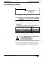
Commissioning Gear Transitions................................................................................................ 9-51
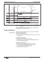
Diagnostic Messages .................................................................................................................. 9-52
DOK-DIAX04-AHS-03VRS**-FK01-EN-P
6 Contents
DIAX04 AHS-03VRS
10 Glossary
10-1
11 Index
11-1
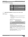
Supplement A: Parameter Description
Supplement B: Diagnostic Message Description
Supplement C: Serial Communications
Sales & Service Facilities
DOK-DIAX04-AHS-03VRS**-FK01-EN-P
System Overview 1-1
DIAX04 AHS-03VRS
1
System Overview
1.1
Range of Uses
DIAX04 is a family of digital, intelligent drives. DIAX04 offers solutions for
applications in the following markets:
• Converting
• Printing
• Packaging
• General Industrial Automation
DIAX04 consists of:
• Operation with the complete line of INDRAMAT motors
• Complete power range from 1kW to 100kW
• User-friendly software features
• Adaptability to various applications by configuring the drive with
optional plug-in cards
1.2
DIAX04 - a Drive Family
There are five application-releated firmware variants available for the
DIAX04 family:
FWA-DIAX04-ELS-0xVRS-MS
• Drive With Electric Gear Function
FWA-DIAX04-SSE-0xVRS-MS
• Drive With Servo Function
FWA-DIAX04-ASE-0xVRS-MS
• Drive With Servo Function, Analog And Parallelinterface
FWA-DIAX04-SHS-0xVRS-MS
• Main Spindle Drives
FWA-DIAX04-AHS-0xVRS-MS
• Drive With Main Spindle Function, Analog- and Parallelinterface
The following function description relates to the firmware variant:
FWA-DIAX04-AHS-0xVRS-MS
• Drive With Main Spindle Function, Analog- and Parallelinterface
For each listed variant, there is individual documentation.
DOK-DIAX04-AHS-03VRS**-FK01-EN-P
1-2 System Overview
1.3
DIAX04 AHS-03VRS
Drive Controllers
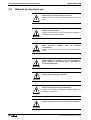
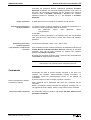
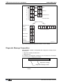
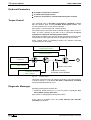
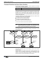
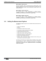
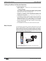
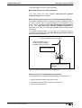
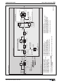
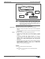
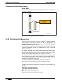
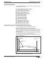
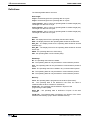
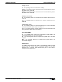
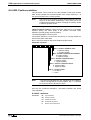
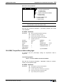
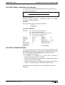
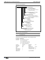
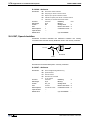
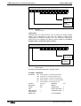
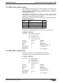
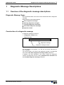
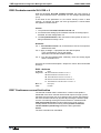
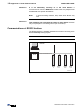
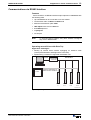
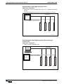
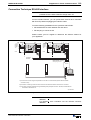
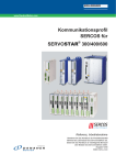
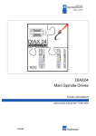
The DIAX04 family consists of 4 drive controller types:
Modular Drive Controllers:
• HDS 02.1
• HDS 03.1
• HDS 04.1
• HDD 02.1 (not possible with DIAX04-AHS)
• HDS 02.2
• HDS 03.2
• HDS 04.2
• HDD 02.2 (not possible with DIAX04-AHS)
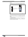
Fig. 1-1:
Drive controllers
DOK-DIAX04-AHS-03VRS**-FK01-EN-P
System Overview 1-3
DIAX04 AHS-03VRS
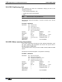
1.4
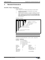
Function Overview: FWA-DIAX04-ASE-02VRS-MS
Command Communications Interfaces
• Analog interface
• Parallel interface
Possible Operating Modes
• Torque control
• Velocity control
• Drive internal interpolation
• Relative Drive internal interpolation
Supported motor types
Rotary motors:
MHD
MKD
2AD
ADF
1MB
MBW
MBS
Supported Measuring Systems
• LSF, DSF, HSF
• Resolver
• Incremental encoder with sine signals, uA or 1V signals
• Gear wheel encoder
• Incremental encoder with rectangular signals, SSI interface
• Encoder with EnDat interface
• Resolver without feedback data memory, gear wheel encoder with
1Vpp-signals
• Resolver without feedback data memory & sine encoder
The possible combinations are described in the chapter "measuring
systems".
DOK-DIAX04-AHS-03VRS**-FK01-EN-P
1-4 System Overview
DIAX04 AHS-03VRS
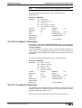
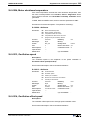
General Functions
• Extensive diagnostics options
• Basic parameter block that can be activated for a defined setting of
the drive parameters to default values.
• Customer passwords
• Error memory and operating hour counter
• Configurable signal status word
• Supports five (5) languages for parameter names and units and
diagnoses (S-0-0095)
• German
• English
• French
• Spanish
• Italian
• Settable drive-internal position resolution
• Evaluation of option (load-side) encoder for position and/or velocity
control
• Evaluates absolute measuring system with setting of absolute
dimension
• Modulo function
• Parametrizable torque force limit
• Current limit
• Velocity limit
• Drive-side error reactions:
best possible standstill "velocity command to zero"
best possible standstill "Torque free"
best possible standstill "velocity command to zero with
ramp and filter
power shutdown with fault
NC reaction with fault
E-Stop function
• Control loop settings
base load function
velocity mix factor
velocity feedforward
• Velocity control loop monitor
• Position control loop monitor
• Drive halt
• Drive-Controlled Homing
• Command "Set Absolute Measuring"
• Analog output
• Analog input
• Digital In- and Outputs
• Oscilloscope function
• Command "Detect marker position“
DOK-DIAX04-AHS-03VRS**-FK01-EN-P
System Overview 1-5
DIAX04 AHS-03VRS
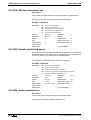
• Encoder emulation
absolute encoder emulation (SSI format)
•
incremental encoder emulation
• Command Positive stop drive procedure
• Command park axis
Main Spindle Function
• A change between four modes is possible
• Four switchable parameter blocks
• Diagnostic outputs for the main spindle messages
• Drive-guided spindle positioning
• Drive-guided oscillating
• Drive-guided gear transitions
• Drive-guided windings transition
• Switchable velocity limit values
• Switchable torque limit values
• Velocity command value switching for C-axis mode
DOK-DIAX04-AHS-03VRS**-FK01-EN-P
1-6 System Overview
DIAX04 AHS-03VRS
Notes
DOK-DIAX04-AHS-03VRS**-FK01-EN-P
DIAX04 AHS-03VRSSafety Instructions for Electrical Drives 2-1
2
Safety Instructions for Electrical Drives
2.1
Introduction
These instructions must be read and understood before the equipment is
used to minimize the risk of personal injury and / or property damage.
Follow these safety instructions at all times.
Do not attempt to install, use or service this equipment without first
reading all documentation provided with the product. Please read and
understand these safety instructions, and all user documentation of the
equipment, prior to working with the equipment at any time. You must
contact your local Indramat representative if you cannot locate the user
documentation for your equipment. A listing of Indramat offices is
supplied in the back of this manual. Request that your representative
send this documentation immediately to the person or persons
responsible for the safe operation of this equipment.
If the product is resold, rented and/or otherwise transferred or passed on
to others, then these safety instructions must accompany it.
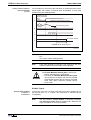
WARNING
DOK-DIAX04-AHS-03VRS**-FK01-EN-P
Improper use of this equipment, failure to follow the
attached safety instructions, or tampering with the
product, including disabling of safety device, may
result in personal injury, severe electrical shock,
death, or property damage!
2-2 Safety Instructions for Electrical Drives
2.2
DIAX04 AHS-03VRS
Hazards by improper use
High voltage and high discharge current!
Danger to life, risk of severe electrical shock and risk of
injury!
DANGER
Dangerous movements!
Danger to life and risk of injury or equipment damage by
unintentional motor movements!
DANGER
High
electrical
connections!
WARNING
voltages
due
to
incorrect
Danger to life, severe electrical shock and serious bodily
injury!
Health hazard for persons with heart pacemakers,
metal implants and hearing aids in proximity to
electrical equipment!
WARNING
Surface of machine housing could be extremely hot!
Danger of injury! Danger of burns!
CAUTION
Risk of injury due to incorrect handling!
Bodily injury caused by crushing, shearing, cutting and
thrusting movements!
CAUTION
Risk of injury due to incorrect handling of batteries!
CAUTION
DOK-DIAX04-AHS-03VRS**-FK01-EN-P
DIAX04 AHS-03VRS
2.3
Safety Instructions for Electrical Drives 2-3
General
• INDRAMAT GmbH is not liable for damages resulting from failure to
observe the warnings given in these instructions.
• Order operating, maintenance and safety instructions in your
language before starting up the machine. If your language is not
available, then numerous other languages are. Please select one that
you understand perfectly.
• Proper and correct transport, storage, assembly, and installation as
well as care in operation and maintenance are prerequisites for
optimal and safe operation of this equipment.
• Trained and qualified personnel in electrical equipment:
Only trained and qualified personnel may work on this equipment or
within its proximity. Personnel are qualified if they have sufficient
knowledge of the assembly, installation, and operation of the product
as well as an understanding of all warnings and precautionary
measures noted in these instructions.
Furthermore, they should be trained, instructed, and qualified to
switch electrical circuits and equipment on and off, to ground them,
and to mark them according to the requirements of safe work
practices and common sense. They must have adequate safety
equipment and be trained in first aid.
• Use only spare parts approved by the manufacturer.
• All safety regulations and requirements for the specific application
must be followed as practiced in the country of use.
• The equipment is designed for installation on commercial machinery.
• Start-up is only permitted once it is sure that the machine in which the
product is installed complies with the requirements of national safety
regulations and safety specifications of the application.
European countries: see Directive 89/392/EEC (Machine Guideline).
• Operation is only permitted if the national EMC regulations for the
application are met.
The instructions for installation in accordance with EMC requirements
can be found in the INDRAMAT document "EMC in Drive and Control
Systems”.
The machine builder is responsible for compliance with the limiting
values as prescribed in the national regulations and specific EMC
regulations for the application.
European countries: see Directive 89/336/EEC (EMC Guideline).
U.S.A.: See National Electrical Codes (NEC), National Electrical
Manufacturers Association (NEMA), and local building codes. The
user of this equipment must consult the above noted items at all
times.
• Technical data, connections, and operational conditions are specified
in the product documentation and must be followed.
DOK-DIAX04-AHS-03VRS**-FK01-EN-P
2-4 Safety Instructions for Electrical Drives
2.4
DIAX04 AHS-03VRS
Protection against contact with electrical parts and not
grounded enclosures
Note: This section pertains to equipment and drive components with
voltages over 50 Volts.
Touching live parts with potentials of 50 volts and higher applied to them
or touching not grounded enclosures can be dangerous and cause
severe electrical shock. In order for electrical equipment to be operated,
certain parts must have dangerous voltages applied to them.
High Voltage!
Danger to life, severe electrical shock and risk of injury!
DANGER
⇒ Only those trained and qualified to work with or on
electrical equipment are permitted to operate, maintain
and / or repair this equipment.
⇒ Follow general construction and safety regulations
when working on electrical installations.
⇒ Before switching on power, the ground wire must be
permanently connected to all electrical units according
to the connection diagram.
⇒ At no time may electrical equipment be operated if the
ground wire is not permanently connected, even for
brief measurements or tests.
⇒ Before beginning any work, disconnect mains or the
voltage source from the equipment. Lock the
equipment against being switched on while work is
being performed.
⇒ Wait five (5) minutes after switching off power to allow
capacitors to discharge before beginning work.
Measure the voltage on the capacitors before
beginning work to make sure that the equipment is
safe to touch.
⇒ Never touch the electrical connection points of a
component while power is turned on.
⇒ Before switching the equipment on, install those
covers and guards provided with the equipment to
prevent contact with live parts. Before operating, cover
and guard live parts properly so they cannot be
touched.
⇒ A residual-current-operated protective device (r.c.d.)
must not be used on an AC drive! Indirect contact
must be prevented by other means, for example, by an
overcurrent protective device.
European countries: according to EN 50178/ 1994.
⇒ Electrical components with exposed live parts must be
installed in a control cabinet to prevent direct contact.
European countries: according to EN 50178/ 1994.
U.S.A: See National Electrical Codes (NEC), National
Electrical Manufacturers Association (NEMA), and
local building codes. The user of this equipment must
consult the above noted items at all times.
DOK-DIAX04-AHS-03VRS**-FK01-EN-P
Safety Instructions for Electrical Drives 2-5
DIAX04 AHS-03VRS
High housing voltage! High leakage current!
Danger to life and limb, danger of injury from electric
shock!
DANGER
⇒ Prior to powering up, connect the electrical equipment,
the housing of all electrical units and motors to the
protective conductor at the grounding points or ground
them. This applies even to brief tests.
⇒ The protective conductor of the electrical equipment
and units must always be connected to the supply
network. Leakage current exceeds 3.5 mA.
2
⇒ Use at least a 10 mm copper conductor cross section
for this protective connection over its entire course!
⇒ Prior to startups, even for brief tests, always connect
the protective conductor or connect with ground wire.
High voltage levels can occur on the housing that
could lead to severe electrical shock and personal
injury.
European countries: EN 50178 / 1994, section 5.3.2.3.
USA: See National Electrical Codes (NEC), National
Electrical Manufacturers Association (NEMA), and local
building codes. The user of this equipment must consult
the above noted items at all times.
2.5
Protection by protective low voltage (PELV) against
electrical shock
All connections and terminals with voltages ranging between 5 and 50
volts on INDRAMAT products are protective low voltages designed in
accordance with the following standards on contact safety:
• International: IEC 364-4-411.1.5
• EU countries: see EN 50178/1994, section 5.2.8.1.
High electrical voltages due to incorrect connections!
Danger to life, severe electrical shock and/or serious
bodily injury!
WARNING
DOK-DIAX04-AHS-03VRS**-FK01-EN-P
⇒ Only that equipment or those electrical components
and cables may be connected to all terminals and
clamps with 0 to 50 volts that are of the protective low
voltage type (PELV = Protective Extra Low Voltage).
⇒ Only connect those voltages and electrical circuits that
are safely isolated. Safe isolation is achieved, for
example, with an isolating transformer, an
optoelectronic coupler or when battery-operated.
2-6 Safety Instructions for Electrical Drives
2.6
DIAX04 AHS-03VRS
Protection against dangerous movements
Dangerous movements can be caused when units have bad interfaces or
motors are connected incorrectly.
There are various causes of dangerous movements:
• Improper or incorrect wiring or cable connections
• equipment is operated incorrectly
• probe parameters or encoder parameters are set incorrectly
• malfunctioning components
• errors in software or firmware
Dangerous movements can occur immediately after equipment is
switched on or even after an unspecified time of trouble-free operation.
Although the monitoring circuits in the drive components make improper
operation almost impossible, personnel safety requires that proper safety
precautions be taken to minimize the risk of personal injury and/or
property damage. This means that unexpected motion must be
anticipated since safety monitoring built into the equipment might be
defeated by incorrect wiring or other faults.
Dangerous movements!
Danger to life and risk of injury or equipment damage!
DANGER
⇒ In the drive component monitoring units, every effort is
made to avoid the possibility of faulty operation in
connected drives. Unintended machine motion or other
malfunction is possible if monitoring units are disabled,
bypassed or not activated.
⇒ Safe requirements of each individual drive application
must be considered on a case-by-case basis by users
and machine builders.
Avoiding accidents, personal injury and/or property
damage:
⇒ Keep free and clear of the machine’s range of motion
and moving parts. Prevent people from accidentally
entering the machine’s range of movement:
- use protective fences
- use protective railings
- install protective coverings
- install light curtains / barriers
⇒ Fences should be strong enough to withstand
maximum possible momentum.
⇒ Mount the Emergency Stop (E-stop) switch in the
immediate reach of the operator. Verify that the
emergency stop works before startup. Do not operate
the machine if it is not working.
⇒ Isolate the drive power connection by means of an
emergency stop circuit or use a start inhibit system to
prevent unintentional start-up.
DOK-DIAX04-AHS-03VRS**-FK01-EN-P
Safety Instructions for Electrical Drives 2-7
DIAX04 AHS-03VRS
⇒ Make sure that the drives are brought to standstill
before accessing or entering the danger zone.
⇒ Disconnect electrical power to the equipment using a
master lock-out and secure against reconnection for:
- maintenance and repair work
- cleaning of equipment
- long periods of discontinued equipment use
⇒ Avoid operating high-frequency, remote control, and
radio equipment near equipment electronics and
supply leads. If use of such equipment cannot be
avoided, verify the system and the plant for possible
malfunctions at all possible positions of normal use
before the first start-up. If necessary, perform a
special Electromagnetic Compatibility (EMC) test on
the plant.
2.7
Protection against magnetic and electromagnetic fields
during operations and mounting
Magnetic and electromagnetic fields in the vicinity of current-carrying
conductors and permanent motor magnets represent a serious health
hazard to persons with heart pacemakers, metal implants and hearing
aids.
WARNING
DOK-DIAX04-AHS-03VRS**-FK01-EN-P
Health hazard for persons with heart pacemakers,
metal implants and hearing aids in proximity to
electrical equipment!
⇒ Persons with pacemakers and metal implants are not
permitted to have access to the following areas:
− Areas in which electrical equipment and parts are
mounted, being operated or started up.
− Areas in which parts of motors with permanent
magnets are being stored, repaired or mounted.
⇒ If it is necessary for a person with a pacemaker to
enter into such an area, then a physician must be
consulted prior to doing so.
⇒ Persons with metal implants or hearing aids must take
care prior to entering into areas described above. It is
assumed that metal implants or hearing aids will be
affected by such areas: A physician must be consulted
prior to working in and/or entering such areas.
2-8 Safety Instructions for Electrical Drives
2.8
DIAX04 AHS-03VRS
Protection against contact with hot parts
Surface of machine housing could be extremely hot!
Danger of injury! Danger of burns!
CAUTION
2.9
⇒ Do not touch housing surface near the source of
heat! Danger of burns!
⇒ Prior to accessing a unit, wait ten (10) minutes to
allow the unit to cool off.
⇒ If hot parts of the equipment are touched, such as the
unit housing in which heatsink and resistor are
located, then this can cause burns.
Protection during handling and installation
All INDRAMAT products should be handled and assembled according to
the instructions in the documentation.
Risk of injury due to incorrect handling!
Bodily injury caused by crushing, shearing, cutting, and
thrusting movements!
CAUTION
⇒ Observe installation instructions and safety regulations
before handling and working on the product.
⇒ Use suitable lifting or moving equipment during
installation. Refer to the user manual for the product.
⇒ Take precautions to avoid pinching and crushing.
⇒ Only use suitable tools specified in the user manuals
and use them according the instructions.
⇒ Use lifting devices and tools correctly and safely.
⇒ Wear appropriate protective clothing, e.g., protective
goggles, safety shoes, protective gloves.
⇒ Never stand under suspended loads.
⇒ Clean up liquids form the floor to prevent personnel
from slipping.
DOK-DIAX04-AHS-03VRS**-FK01-EN-P
Safety Instructions for Electrical Drives 2-9
DIAX04 AHS-03VRS
2.10 Battery safety
Batteries contain reactive chemicals. Incorrect handling can result in
injury or equipment damage.
Risk of injury due to incorrect handling!
CAUTION
⇒ Do not attempt to reactivate dead batteries by heating
or other methods (danger of explosion and corrosion).
⇒ Never charge batteries (danger from leakage and
explosion).
⇒ Never throw batteries into a fire.
⇒ Do not take batteries apart.
⇒ Handle carefully. Incorrect extraction or installation of a
battery can damage equipment.
Note: Environmental protection and disposal! The batteries contained
in the product should be considered as hazardous material for
land, air and sea transport in the sense of the legal requirements
(Danger of explosion). Dispose of batteries separately from other
refuse. Observe the legal requirements in the country of
installation.
DOK-DIAX04-AHS-03VRS**-FK01-EN-P
2-10 Safety Instructions for Electrical Drives
DIAX04 AHS-03VRS
Notes
DOK-DIAX04-AHS-03VRS**-FK01-EN-P
General Instructions for Installation 3-1
DIAX04 AHS-03VRS
3
General Instructions for Installation
3.1
Definition of Terms, Introduction
It is helpful to explain the terms used in this document so that they will be
better understood.
Parameter
Communication with the drive occurs (with a few exceptions) with the
help of parameters. They can be used for
• Setting the configuration
• Parameterizing the control/drive settings
• Accessing control/drive functions and commands
• Cyclical or acyclical (depending on requirements) transmission of
command and actual values
Note:
Parameter block transitions
All of the drive's operating data are identified by ID numbers.
Specific parameter blocks have been are present at four different
locations within the main spindle firmware. During operatioons, however,
only one parameter block is active. During operation it is possible to
change the active block. These "switchable parameters" are always
identified with the -x- in their ID numbers. The non-switchable ones are
identified with an -0-.
All those parameters in a switchable block in the drive are listed in S-X0219, IDN list of parameter blocks.
The Data Status
Each parameter is provided with a data status, which can also be read. It
serves the following purposes:
• Identifying the validity/invalidity of the parameter
• Contains the command acknowledgment if the parameter acts as a
command
(see also Commands)
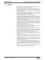
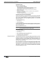
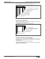
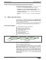
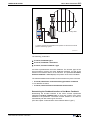
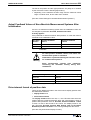
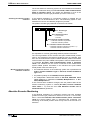
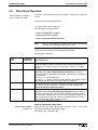
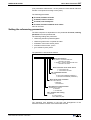
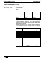
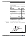
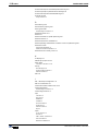
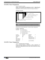
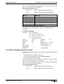
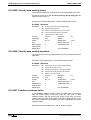
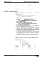
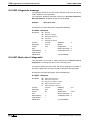
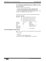
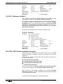
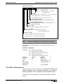
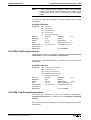
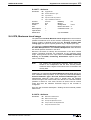
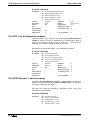
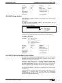
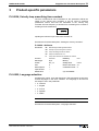
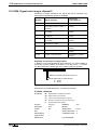
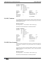
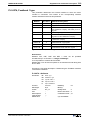
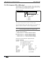
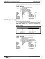
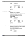
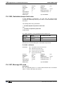
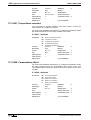
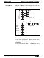
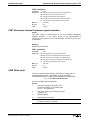
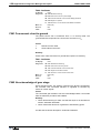
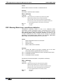
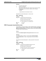
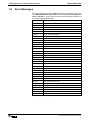
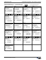
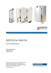
Paramter structure
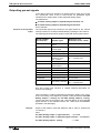
There are seven different data block elements for each parameter.
These can be read/write accessed either via a user data interface by a
higher-ranking control or a parametrization surface.
Element No.:
Designation:
Remarks:
1
ID Number
Parameter identification
2
Name
can be changed in language
selection
3
Attribute
contains data length, type and
decimal places
4
Unit
can be changed in language
selection
5
Minimum Input Value
contains the minimum input
value of the operating data
6
Maximum Input Value
contains the maximum input
value of the operating data
7
Fig. 3-1:
DOK-DIAX04-AHS-03VRS**-FK01-EN-P
Operating Data
actual parameter value
Data blocks or parameter structure
3-2 General Instructions for Installation
Write Accessibility
DIAX04 AHS-03VRS
Only the operating data can be changed; all other elements can only be
read.
The operating data can be write-protected either continuously or
temporarily.
The write accessing of the operating data depends on the relevant
communications phase.
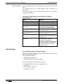
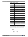
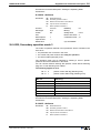
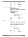
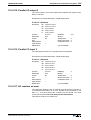
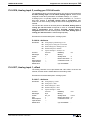
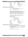
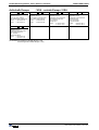
Possible Error Messages when Reading and Writing
Operating Data
Error:
Reason:
0x7002, data transmitted too short
0x7003, data transmitted too long
0x7004, Data not changeable
The operating data is write-protected
0x7005, Data currently writeprotected
The operating data cannot be written to
in this communication phase (see
Supplement A:Parameterdescription)
0x7006, Data smaller than
minimum value
The operating data is smaller than its
minimal input value
0x7007, Data larger than
maximum value
The operating data is larger than its
maximum input value
0x7008, Data is not correct
The value could not be accepted as
written because internal tests lead to a
negative result
0x7009, data write protected with
password
The parameter cannot be write
accessed as the customer
password was activated in
parameter S-0-0267, Password. All
parameters listed in S-0-0192, IDNlist of backup operation data are
therefore locked.
Fig. 3-2:
Error messages while reading/writing operating data
Data Storage
Non-Volatile Parameter Storage Registers
Various non-volatile parameter storage registers that buffer operating
data are contained in the drive.
The operating data apply to:
• setting the configuration or
• parameterizing the control drive settings
Each time operating data is written to it is stored.
The following modules contain non-volatile memory:
• Control drive
• Motor feedback (optional)
• Programming module
DOK-DIAX04-AHS-03VRS**-FK01-EN-P
General Instructions for Installation 3-3
DIAX04 AHS-03VRS
Parameters Stored in the Digital
Drive
All operating data that apply only to the drive controller and that cannot
be changed by the user are stored in the digital drive. This consists of the
following parameters:
• S-0-0110, Amplifier Peak Current
• S-0-0112, Amplifier Nominal Current
• S-0-0140, Controller Type
• P-0-0518, Amplifier Nominal Current 2
• P-0-0519, Amplifier Peak Current 2
• P-0-4002, Current-Amplify-Trim Phase U
• P-0-4003, Current-Amplify-Trim Phase V
• P-0-4015, Intermediate Voltage
• P-0-4035, Trim-Current
Parameter Storage in Motor Feedback
All motor-dependent parameters are stored in the motor feedback with
MHD, MKD and MKE motors.
Additionally, parameters for the "load default" function and the motor
feedback are stored here.
All parameters stored in the motor feedback data memory are there with
both parameter block number 0 and 7.
In parameter block 7 (e.g., S-7-0100) the original data without write
access are stored in the motor feedback data memory. These are copied
after powering up into the parameters of parameter block 0 (e.g., S-00100) .
Note:
Parameters Stored in DSM
Programming Module
The parameters of parameter block 0 take effect.
All application parameters are stored in the programming module (control
loop, mechanical system, interface parameters and so on).
All ID numbers backed up in this module are listed in parameter S-00192, IDN-list of backup operation data.
If the programming module is exchanged then these application
parameters must be read out before hand so that they can be written into
the new module after the exchange.
Note:
By switching the programming module when devices are
exchanged, the characteristics of the device that has been
exchanged can be easily transferred to the new device.
Data Saving
To save the data of the axis, all important and changeable parameters of
the axis are stored in the list S-0-0192, IDN-List of backup operation
data. By saving the parameters listed there with the control or
parametrization surface, you can obtain a complete data backup of this
axis after the first setup (Backup&Restore-function).
Parameter Buffer Mode
The drive controller is capable of storing data that is transmitted via the
user data channel (e.g., service channel) either temporarily or
permanently.
The parameter S-0-0269, Parameter buffer mode determines what will
be done with the parameters.
DOK-DIAX04-AHS-03VRS**-FK01-EN-P
3-4 General Instructions for Installation
DIAX04 AHS-03VRS
Basic parameter block
The drive parameters are set to default values at the factory. By
executing the command P-0-4094, C800 Command Base-parameter
load it is possible to reproduce this state at any time. The default
parameter set is constructed so that
• all important monitoring functions are activated
• all optional drive functions are deactivated
• limit values for position are deactivated
• limit values for torque/force are set to high values and
• limit values for velocity and acceleration are set to lower values
The set mode is velocity control.
Note:
The default parameter set does not guarantee a matching of
the drive to the machine. The relevant settings must be made
when first starting up the axis.
(See also: Basic drive functions and Commissioning Guidelines.)
Running the "load basic parameter block" function
automatically
Drive firmware is stored on the programming module. In the event of a
firmware exchange, the drive controller will detect this the next time the
machine is switched on. In this case, the message "PL" appears on the
7-segment display. By pressing the "S1" key, the function default
parameter set is activated.
Note:
Any previous parameter settings are lost with the replacement
of the firmware followed by "load base parameter block". If
this is to be prevented, then the parmeters must be stored
prior to an exchange and must be reloaded after exchange
and load default parameter set .
Note:
As long as the drive displays "PL" and the command is active,
then communication via the serial interface (e.g.: with
DriveTop) is not possible.
Password
All important axis-specific parameters are stored in the programming
module. If, e.g., a controller is replaced because of a defect then the
features can be transferred to the new controller by simply using the old
module. The affected parameters are stored in S-0-0192, IDN-List of
backup operation data. To secure these parameters against unwanted
or non-authorized changes, the customer password can be activated.
DOK-DIAX04-AHS-03VRS**-FK01-EN-P
General Instructions for Installation 3-5
DIAX04 AHS-03VRS
Accessing the password function implements parameter S-0-0267,
Password. At delivery, this customer password function is not active. In
this case, all axis-specific parameters can be changed. The character
sequence "007" in S-0-0267, Password is displayed. the customer
password function is activated, so "***" isd displayed in S-0-0267,
Password.
Length of password
Activating and changing the
customer password
At least three and no more than ten characters can be entered.
To activate function customer password or change the passsword, it is
necessary to input the following character sequence:
"old
password",
"new password"
space,
"new
password",
space,
in S-0-0267.
If function customer password is not activated, then the old password
"007" must be used. If the function is active, then use the old customer
password.
Deactivating the function
customer password
Lock parameter or make it write
accessible
"old customer password", space, "007", space, "007"
Upon activating function customer password, the parameters stored in S0-0192, IDN-list of backup operation data after powering up, are write
protected. They can be write accessed by entering the customer
password in S-0-0267, Password.
By writing any character (minimum three, maximum ten) the parameters
in S-0-0192 can again be write accessed.
Note:
Parameters stored in the motor feedback or drive controller
data memory can generally not be changed by the user.
Commands
Commands are used to control complex functions in the drive. For
example, the functions "Drive-Controlled Homing Procedure" or
"Transistion Check for Communication Phase 4" are defined as
commands.
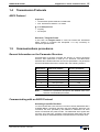
Each command that is started
must also be cleared.
A primary control can start, interrupt or erase a command.
Each command has a parameter with which the command can be
controlled.
While a command is being executed, the diagnostic message "Cx" or
"dx" appears in the H1 display, where x is the number of the command.
list of all procedure commands
DOK-DIAX04-AHS-03VRS**-FK01-EN-P
All commands used are stored in parameter S-0-0025, IDN-list of all
procedure commands.
3-6 General Instructions for Installation
DIAX04 AHS-03VRS
Command Types
There are 3 command types.
• Drive-Controlled Command
- Eventually leads to an automatic drive operation or motion
- Can be started only when controller enable is set
- Deactivates the active operating mode during its operation
• Monitor Command
- Activates or deactivates monitors or features in the control drive
• Management Command
- executes management tasks; is not interruptable
Command Input and Acknowledgment
Control and monitoring of command execution occurs via the command
input and command acknowlegment. The command input tells the drive if
the command should be started, interrupted or ended. The commanded
value is the operating data of the applicable parameter. The command
input value can be:
• not set and enabled (0)
• interrupted (1)
• set and enabled (3)
In the acknowledgement, the drive informs about the extent to which a
command has been executed. This is then displayed in the data status of
the command parameter.
Also see: "Data block structure".
Note:
The command status can be obtained by conducting a write
error on parameter element 1 (data status).
The condition can be:
• not set and enabled (0)
• in process (7)
• error, command execution not possible (0xF)
• command execution interrupted (5)
• command properly executed (3)
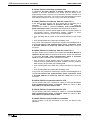
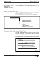
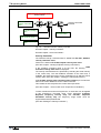
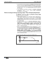
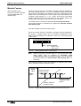
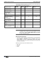
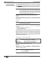
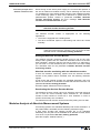
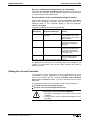
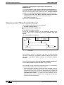
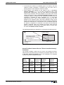
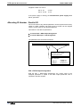
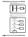
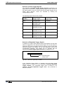
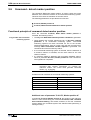
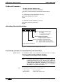
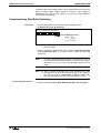
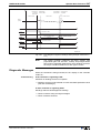
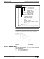
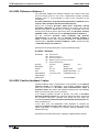
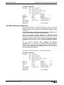
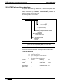
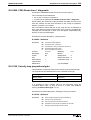
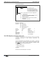
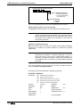
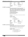
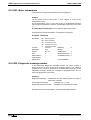
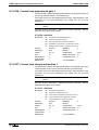
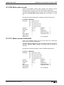
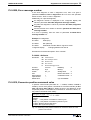
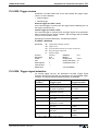
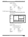
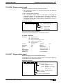
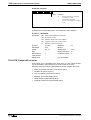
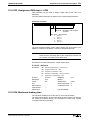
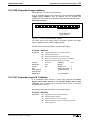
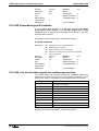
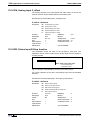
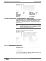
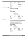
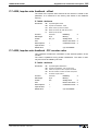
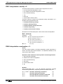
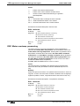
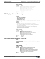
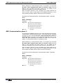
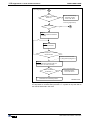
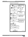
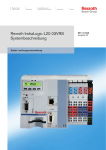
Change Bit Command
The Change Bit Command in the Drive Status Word helps the control
recognize a change in the command acknowledgment by the drive. The
bit is set by the drive if the command acknowledgment changes from the
condition in process (7) to the condition error, command execution not
possible (0xF) or command properly executed (3). The bit is cleared if
the master clears the input (0).
The control system will recognize if the drive sets the Command Change
Bit bit command. It can read the corresponding data status of the
command or the command itself, which was set sometime but has not
been cleared. The control system will recognize from this if the command
ended with or without an error in the drive. Afterwards this command
should be cleared by the control.
DOK-DIAX04-AHS-03VRS**-FK01-EN-P
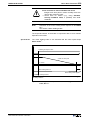
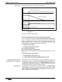
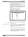
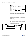
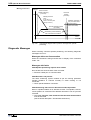
General Instructions for Installation 3-7
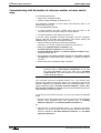
DIAX04 AHS-03VRS
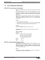
Date of
command
parameter
= handcap
Beginning of
the command
3
0
Data status of
the command
parameter
7
=acknow3
ledgment
0
Sbit command
change in drive
status message
1
Command finished
Handicap
t
t abt. 8msec
Command at work
Command finished without error
Command cleared
t
t abt. 8msec
t
Sv5021d1.fh5
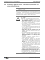
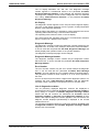
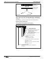
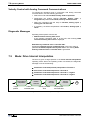
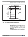
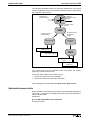
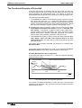
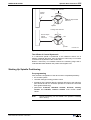
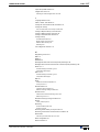
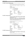
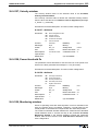
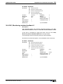
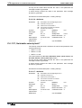
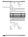
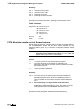
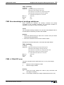
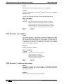
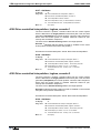
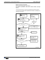
Fig. 3-3:
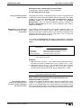
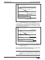
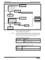
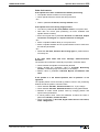
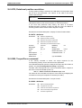
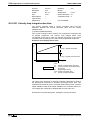
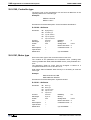
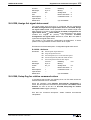
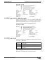
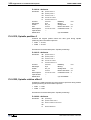
Date of
command
parameter
= handcap
Input, acknowledgment and Command Change Bit during proper
execution
Beginning of the
command
3
0
Data status of OxF
the command
parameter
7
=acknow3
ledgment
0
Sbit command
change in drive
status message
1
Command cleared
Command at work
t abt. 8msec
t
Command finished
Handicap
t abt. 8msec
t
t
Sv5022d1.fh5
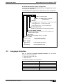
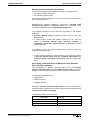
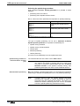
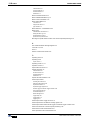
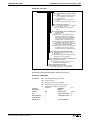
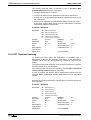
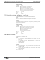
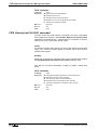
Fig. 3-4:
Input, acknowledgment and Command Change Bit during erroneous
execution
A delay time of up to 8ms can occur in the drive between receiving the
command input and setting the command acknowledgment.
Operating Modes
Operating modes define which command values will be processed in
which format, leading to the desired drive motion. They do not define how
these command values will be transmitted from a control system to the
drive.
One of the four selectable operating modes (S-0-0032…S-0-0035) is
active when:
• the control and power supply is ready for operation and the controller
enable signal is positive.
• The drive displays "AF" in the H1 display.
Note:
All implemented operating modes are stored in parameter
S-0-0292, List of all operation modes.
See also: "Operating modes"
DOK-DIAX04-AHS-03VRS**-FK01-EN-P
3-8 General Instructions for Installation
DIAX04 AHS-03VRS
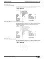
Warnings
Warnings do not cause
automatic shutdowns
Many areas are monitored in connection with operating modes and
parameter settings. A warning will be generated if a state is detected that
allows proper operation for the time being, but will eventually generate an
error and thereby lead to a shutdown of the drive if this state continues.
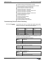
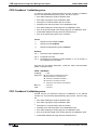
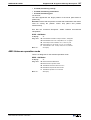
Warning Classes
The warning class is evident
from the diagnostic message
Warnings can be separated into 2 classes. They are differentiated by
whether the drive executes an automatic reaction when the warning
appears.
Warning Class:
Diagnostic
Message:
With drive response
E8xx
Drive Response:
reacts on its own specifically
in terms of any occurring
warnings
Without drive response
E2xx
-Fig. 3-5:
Breakdown of the Warning Classes
Note:
Warnings cannot be cleared externally.They pend until the
conditions that lead to the warning are no longer present.
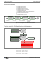
Error
Many areas are monitored in connection with operating modes and
parameter settings. An error message is generated if a condition is
encountered which no longer allows proper operation
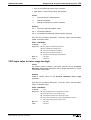
Error Classes
The error class is evident from
the diagnostic message.
Errors are separated into four different drive's error response:
Error Class:
Diagnostic
Message:
Drive Response:
Fatal
F8xx
Torque free switching
Travel range
F6xx
Velocity command value switched to
zero
Interface
F4xx
In accordance with best possible
deceleration
Non-fatal
F2xx
In accordance with best possible
deceleration
Fig. 3-6: Error class divisions
Drive's Error Response
If an error state is detected in the drive, the drive's error response will
automatically be executed as long as the drive is in control. The H1
display flashes Fx / xx. The drive's reaction to interface and non-fatal
errors can be parameterized with P-0-0119, Best possible
deceleration. The drive switches to torque-free operation at the end of
each error reaction.
DOK-DIAX04-AHS-03VRS**-FK01-EN-P
General Instructions for Installation 3-9
DIAX04 AHS-03VRS
Clearing Errors
Errors must be externally
cleared.
Errors are not automatically cleared; they are cleared externally by:
• Initiating the command S-0-0099, C500 Reset class 1 diagnostic or
• Pressing the "S1" key.
With analog communications ist also possible to clear the error with the
ext. input "CLR" of the DAE02.x card.
See also chapter: "Command Communications with Analog Interface".
If the error state is still present, then the error will be immediately
detected again.
Clearing Errors When Controller Enable Is Set
If an error is discovered while operating with set controller enable, the
drive will execute an error response. The drive automatically deactivates
itself at the end of each error response; in other words, the power stage
is switched off and the drive switches from an energized to a deenergized state.
To reactivate the drive:
• clear the error
• enter a 0-1 edge bit into the controller enable
Error memory
Error memory and operating hour counter
Once errors are cleared, they are stored in an error memory. The last 19
errors are stored there and the times they occurred.
Errors caused by a shutdown of the control voltage (e.g., F870 +24Volt
DC error ) are not stored in the error memory.
operating hour
Simultaneously, there is an operating hour counter for control and power
sections of the drive controller. This function has the following
parameters:
• P-0-0190, Operating hours control section
• P-0-0191, Operating hours power section
• P-0-0192, Error recorder diagnosis number
• P-0-0193, Error recorder, operating hours control section
IDN List of Parameters
There are parameters in the drive that, in turn, contain ID numbers of
drive parameters. These support the handling of the drive parameters
with parametrization programs (e.g., Drivetop, Serctop, and so on).
S-0-0017, IDN-list of all operation data
The ID numbers of all parameters in the drive are in this parameter. This
list supports, for example, the parametrization program in the menu of
which "All drive parameters" the information as to which ID number is in
this drive firmware is stored.
DOK-DIAX04-AHS-03VRS**-FK01-EN-P
3-10 General Instructions for Installation
DIAX04 AHS-03VRS
S-0-0192, IDN-list of backup operation data
In parameter S-0-0192, IDN-list of backup operation data the ID
numbers of all those parameters are stored, that are stored in the
programming module. These are the parameters that are needed for a
proper operation of the drive. The control or the parametrization program
uses this ID number list to secure a copy of the drive parameters.
S-0-0021, IDN-list of invalid op. data for comm. Ph. 2
In the data of these ID lists, the drive enters the ID numbers out of
parameter S-0-0018, IDN-list of operation data for CP2 which are
recognized as invalid in command S-0-0127, C100 Communication
phase 3 transition check. Parameters are recognized as invalid if:
• their checksums, that are stored together with the operating data in a
non-resident memory (programming module, amplifier or motor
feedback data memory), do not fit to the operating data,
• their operating data is outside of the minimum/maximum input range
or
• their operating data has violated the plausibility rules.
In any event, the parameters entered upon negative acknowledgement of
command S-0-0127, C100 Communication phase 3 transition check
in S-0-0021, IDN-list of invalid op. data for comm. Ph. 2 must be
corrected.
S-0-0022, IDN-list of invalid op. data for comm. Ph. 3
The drive enters the ID numbers out of parameter S-0-0019, IDN-list of
operation data for CP3 into the data of this ID list, which were detected
in command S-0-0128, C200 Communication phase 4 transition
check as invalid. Parameters are detected as invalid if:
• their checksum, stored together with the operating data in a nonresident memory (programming module, amplifier or motor feedback
data memory) do not match the operating data,
• their operating data are outside of the minimum/maximum input limits
or
• their operating data has violated the plausibility rules.
In any event, the parameters entered upon negative acknowledgement of
command S-0-0128, C100 Communication phase 4 transition check
in S-0-0022, IDN-list of invalid op. data for comm. Ph. 3 must be
corrected..
S-0-0018, IDN-list of operation data for CP2
The ID numbers that were checked for validity in command S-0-0127,
C100 Communication phase 3 transition check are stored in S-00018, IDN-list of operation data for CP2.
S-0-0019, IDN-list of operation data for CP3
The ID numbers that were checked for validity in command S-0-0128,
C200 Communication phase 4 transition check are stored in S-00019, IDN-list of operation data for CP3.
S-0-0025, IDN-list of all procedure commands
The ID numbers of all the commands in the drive are stored in this
parameter.
DOK-DIAX04-AHS-03VRS**-FK01-EN-P
General Instructions for Installation 3-11
DIAX04 AHS-03VRS
3.2
Parametrization Mode - Operating Mode
Drive controllers with analog interface immediately go into operation
mode once the control voltage of the controller is switched on.
The parametrization surfaces which communicate with the controller via
the RS232/485 can switch between the parametrization mode and the
operation mode as long as the drive is not in control.
The switch from parametrization to operating mode is controlled by start
and end commands
• S-0-0127, C100 Communication phase 3 transition check
• S-0-0128, C200 Communication phase 4 transition check
• P-0-4023, C400 Communication phase 2 transition
If the drive reaches phase 4 without an error, then the message (H1)
"bb" appears on the 7-segment display on the front of the drive amplifier.
The corresponding diagnosis is: A013 Ready for power on
operating
mode
communication phase 4
communications
phase 4 transition
S-0-0128
parametrization
modus
communication phase 3
communications
phase 3 transition
S-0-0127
switching from
phase 4 to 2
P-0-4023
communication phase 2
Fig. 3-7:
The communications phases
Note:
The evaluation of the measuring systems as well as the
processing of the encoder emulations only takes place in
operating mode. Switching from operating mode into
parametrization mode means that these functions are no
longer active. The switch into operating mode always starts a
new initialization of all the functions within the drive.
Checks in the Transition Commands
To switch from communication phases 2 to 3 and 3 to 4, it is necessary
to activate transition checks in the drive first. This includes a number of
checks and parameter conversions.
The reasons for and assistance with transition command errors are
specified in the diagnostics description.
DOK-DIAX04-AHS-03VRS**-FK01-EN-P
3-12 General Instructions for Installation
DIAX04 AHS-03VRS
S-0-0127, C100 Communication phase 3 transition check
It is checked in transition command C1 whether the values input for the
parameters make any sense and whether analog interfaces DAE02.xM
and parallel interface DEA4.xM have been inserted or not.
Check for correct plug-in card
If the right DAE card is not in, then error
• C116 DAE not plugged in
is generated
If DEA card is not in, then error
• C119 DAE4 not plugged in
is generated
S-0-0128, C200 Communication phase 4 transition check
During this command, the following checks are run.
Checking P-0-4014 for
plausibility
If in parameter P-0-4014, Motor type 1 (MHD) or 5 (MKD/MKE) are
selected and the motor feedback data memory has not found that type,
then command error
• C204 Motor type P-0-4014 incorrect
is generated.
Checking validity
If a parameter needed for transition to phase 4 has never been written
into, and its backup is faulty, then command error
• C201 Invalid parameter(s) (->S-0-0022)
is generated. The ID number of the faulty parameters are listed in
• S-0-0022, IDN list of invalid op. data for comm. Ph. 3
and are made valid by writing into.
Reading the controller memory
The drive controller reads the EEPROM memory, of the drive controller
operating data. If an error occurs during this process, then command
error:
• C212 Invalid amplifier data (->S-0-0022) appears.
The ID number of the faulty parameter is written in
• S-0-0022, IDN-list of invalid op. data for comm. Ph. 3.
Checking whether optional
encoder is needed
Check whether a second encoder is present or not as per operating
mode parameters S-0-0032 through 35 or homing parameter S-0-0147. If
there is not one present ( parameter P-0-0075, Feedback 2 type = 0)
then the faulty operating mode parameters or homing parameters appear
in:
• S-0-0022, IDN-list of invalid op. data for comm. Ph. 3
Command error
• C210 Feedback 2 required (->S-0-0022).
Checking whether motor
encoder is availablet
Check whether a motor encoder is available (P-0-0074, Feedback type
1 = 0) and no "2" is entered in function parameter P-0-0185, Function of
encoder 2 for load-side motor encoder. If this is the case, then
command error
• C236 Feedback 1 required (P-0-0074)
is generated.
Checking motor encoder
settings
If the encoder parametrized in parameter P-0-0074, Feedback type 1 is
not available, or its data cannot be read, then this error message is
generated
DOK-DIAX04-AHS-03VRS**-FK01-EN-P
General Instructions for Installation 3-13
DIAX04 AHS-03VRS
• C217 Feedback1 data reading error
Checking optional encoder
settings
If the encoder interface selected in parameter P-0-0075, Feedback type
2 is already occupied by the motor encoder, then this error message is
generated:
• C234 Encoder combination not possible
generated.
If the needed plug-in card for the second encoder has not been inserted,
then error message
• C233 Encoder 2 interface not present
is generated.
If a second encoder with feedback data memory is used but its data
cannot be read, then error message
• C218 error when reading data of encoder 2
is generated. If parameter P-0-0185, Funktion Encoder 2 "load-side
motor encoder" is selected, but there is no rotary asynchronous motor,
then error message
• C235 Load-side motor encoder only with asynchronous motor
is generated.
Reading out feedback data
memory
The parameters stored in the memory of motors with feedback data
memory are read. If an error occurs during this process, then command
error
• C211 Invalid feedback data (->S-0-0022) is generated.
Checking maximum travel
range
Check whether an internal position resolution has been set via parameter
S-0-0278, Maximum travel range which guarantees the correct
commutation of the motor. If not, then this command error appears:
• C223 Input value for max. range too high.
Checking scaling
Check internal ability to illustrate conversion factors from display format
to an internal one and vice versa for scaling-dependent data. If an error
occurs, then one of the following command errors can be generated:
• C213 Position data scaling error
• C214 Velocity data scaling error
• C215 Acceleration data scaling error
• C216 Torque/force data scaling error
Checking all parameters for
extreme values and possible bit
combinations
All parameters are checked for maintaining extreme values or
permissible bit combinations. If an error occurs, then command error
• C202 Parameter limit error (->S-0-0022)
is generated. The ID number o the faulty parameter is listed in
• S-0-0022, IDN-list of invalid op. data for comm. Ph. 3
and must be corrected.
Checking modulo range
Checking whether an activated modulo scaling of the position from
parameter S-0-0103, Modulo value is possible. If it is not, then
command error
• C227 Modulo range error
is generated.
DOK-DIAX04-AHS-03VRS**-FK01-EN-P
3-14 General Instructions for Installation
Checking the conversion of
internal formats
DIAX04 AHS-03VRS
The physical values of parameters (input format with decimal places and
units) are converted to internal formats. This conversion is monitored. If
incongruencies are detected during this process, then command error
• C203 Parameter calculation error (->S-0-0022)
is generated. The ID number of the faulty parameter is listed in
• S-0-0022, IDN-list of invalid op. data for comm. Ph. 3
and must be corrected.
Checking encoder initialization
Encoder initialization is listed. Errors can occur depending on encoder
type (e.g., index length wrong in DSF feedback). Then one of the
following command error
• C220 Feedback 1 initializing error
• C221 Feedback 2 initializing error
is generated.
Checking controller type
Depending on controller type, various internal settings are performed. If
parameter S-0-0140, Controller type cannot be read, then command
error
• C228 Controller type S-0-0140 wrong
is generated.
Überprüfung des Coprozessors
Wird die Initialisierung des Coprozessors nicht korrekt ausgeführt, wird
die Diagnose
• C225 Coprozessor nicht bereit zur Initialisierung
is generated
Check parameter for automatic
gear and windings switch
If the parameters for the automatic gear/windings switch is not correct,
then the diagnosis
• C230 Preselection of gearstages/Y-D-connection incomplete
is generated.
Checking emulator hardware
If the initialization of the emulator hardware is not correctly performed,
then the diagnosis
• C231 Emulator not loadable
is generated.
Absolute encoder montioring
If the actual position of an absolute encoder is outside of the range of the
current actual position prior to the last shutdown of the unit +/- P-0-0097,
Absolute encoder monitoring window, then error
• F276 Absolute encoder outside of monitoring window
is generated. The acknoweldgement of the transition command is not
faulty in this case but rather the error must be cleared by executing
command S-0-0099, C500 Reset class 1 diagnostics.
(Also see section: "Clearing error").
DOK-DIAX04-AHS-03VRS**-FK01-EN-P
General Instructions for Installation 3-15
DIAX04 AHS-03VRS
3.3
Commissioning Guidelines
For commissioning drive controllers, the parametrization interface
DRIVETOP can be used.
The procedures for commissioning a drive controller entail 11 steps (IBS1..11). The sequence is illustrated below.
Initial start-up, Establishing the initial state using command P-0-4094, C800
Load base parameters command
Velocity and acceleration values limited to small values / Position and torque limits
not active / Operating mode - velocity control / All optional functions are deactivated
IBS-1, Motor configuration
MDD/MKD/MHD
motor
no
Set motor type / motor-dependent parameters (from data
sheet) / temperature monitoring / possible asynchronous
parameters / possible motor holding brake
yes
IBS-2, Determining the Operating Mode
Selection of the primary and secondary mode / Operating mode-specific
settings
IBS-3, Pre-setting mechanical system of axia dn the measuring system
Gears, feed rate constant and maximum travel range / illustrative formats for position,
velocity, acceleration / motor measuring system / possible external measuring system
IBS-4, Setting Error Reations and Emergency Stops
Best possible deceleration / NC reaction / power off with fault / Emergency-stop
function
IBS-5, Pre-setting control loop
Automatic loop tuning / by loading base values / using data sheet
Motor encoder can move axis
IBS-6, Check mechanical system of axis and meauring system
Gears, feed rate constant / polarity of position, velocity and acceleration / motor
measuring system / possible external measuring system
IBS-7, Position, Velocity and Torque Limitations
Position limit values and travel range limit switch / velocity limit values / torque limit
values
IBS8, Possible optimizing the control loop
Velocity and position control loop / possible torque friction compensation / possible
acceleration pre-control
IBS-9, Establishing the absolute referenc dimension
Set absolute dimension or use drive-controlled referencing
IBS-10, Other settings
Drive halt / Status messages / Optional drive functions
IBS-11, Checking Drive Dimensions
Torque/force check / Weight compensation / Regenerated energy
End of Initial Start-Up
Fig. 3-8:
DOK-DIAX04-AHS-03VRS**-FK01-EN-P
Commissioning guidelines
FD5020X1.FLO
3-16 General Instructions for Installation
DIAX04 AHS-03VRS
IBS-1, Motor configuration
motor without data memory
These guidelines are needed in the case where the motor used does not
have a motor feedback memory. It is necessary with these motors
• to enter the parameters for motor features (peak current, maximum
velocity, etc.) using the data sheet or with DRIVETOP using data from
the motor data bank.
• The parameters for the motor temperature warning and off thresholds
must be parametrized as well
• and giving a motor holding brake, these must be properly set also.
motor with data memory
Those motors with data memory such as
• MHD and
• MKD motors
are recognized by the drive and motor parameters are automatically set.
(See also chapter: "Setting the motor type“.)
IBS-2, Determining the Operating Mode
In this step, the main and auxiliary operating modes are selected.
Operating-mode specific settings must be made.
In particular, necessary limit values, optionally usable filters and the
available operating modes must be defined.
(Also see section: "Operating Modes")
IBS-3, Presetting the axis mechanics and measuring systems
In this step, the parameters needed for determining and processing
position, velocity and acceleration data are set. These include the
following parameters for the following settings:
• mechanical gear ratio between motor and load as well as any existing
feedrate constants of the drive of linear slides
• scaling settings for showing position, velocity and acceleration
parameters of the drive. This sets, for example, whether the data is
motor shaft or load related and which LSB valence these have, e.g.,
position data with 0.001 degrees or 0.0001 inches and so on.
• Interfaces, rotational directions and the resoluton of the motor
encoder, and where available, optional encoders.
(See also chapter :
-"Physical Values Display Format"
-"Mechanical Transmission Elements" and
-"Setting the Measurement System").
IBS-4, Setting the error reactions and E-stop
In this step, the reaction of the drive in the event of an error is set as well
as the triggering of the drive's own E-stop input. The following
parametrizations must be performed:
• type and mode of error reactions in drive
• selection whether NC reaction in error case should happen
• selection whether and when the power supply is switched off and
whether a package reaction is to be conducted
• Configuration of the E-stop input
(See also chapter:
"Drive Error Reaction“)
DOK-DIAX04-AHS-03VRS**-FK01-EN-P
General Instructions for Installation 3-17
DIAX04 AHS-03VRS
IBS-5, Pre-setting Control Loop
The parameters for current, velocity and position control loops are set in
this step. This is done either by:
• Execute command S-0-0262, C700 Command basic load or
• by inputting the controller values specified in the data sheet.
Setting the control loop in this way makes ensures a good level of quality
for most applications. Should additional optimization of the control loop
parameters become necessary (velocity and position control loop
parameters, compensation functions and precontrol), then use
commissioning step no. 8.
(See also chapter: "Control loop settings".)
IBS-6, Checking axis mechanics and measuring system
The presettings made in IBS 2 are checked here and modified, if
necessary. This means that the axis must be moved by jogging. The
following checks must be made:
• check the rotational direction of the motor encoder. With non-inverted
position polaritiy (S-0-0055, Position polarities = 0), the values in
parameter S-0-0051, Position feedback 1 value should have a rising
order with a clockwise rotation of the motor. (This check need not be
performed in MDD and MKD motors. If this is not the case, then bit 2
in S-0-0277, Position feedback 1 type must be inverted.
• By moving the axes and examining the position feedback value of the
motor encoder in parameter S-0-0051, Position feedback 1 value it
can be controlled whether a distance in this process is correctly
displayed. If not, then the settings for mechanical gear ratio and
encoder resolution must be checked.
• Given a second encoder, by moving the axis and examining the
position feedback value of the external encoder in parameter S-00053, Position feedback 2 value it can be checked whether a
distance is correctly displayed with this process. S-0-0051, Position
feedback 1 value and S-0-0053, Position feedback 2 value should
run parallel when jogging a specific path. If not, then check the
settings in P-0-0075, Feedback type 2, S-0-0117, Feedback 2
Resolution, S-0-0115, Position feedback 2 type and P-0-0185,
Function of encoder 2.
(See also chapter :
-"Physical Values Display Format"
-"Mechanical Transmission Elements" and
-"Setting the Measurement System").
IBS-7, Limits for position, velocity and torque
In this step the limit values for the axis velocity and maximum drive
torque/force are parametrized.
(See also chapter:
-"Torque/force limiting",
-"Limiting velocity".)
DOK-DIAX04-AHS-03VRS**-FK01-EN-P
3-18 General Instructions for Installation
DIAX04 AHS-03VRS
IBS-8, Optimizing the control loop
This step is only necessary if the settings for velocity and position control
loops in IBS 4 did not achieve the needed quality. As such, optimize the
control behavior as follows:
• modify the parameter for velocity and position control loops
• possibly activate the acceleration pre-control
• possibly activate the friction torque compensation
• possibly activate the velocity mixture and
• possibly activate the notch filter.
(See also chapter:
"Control loop settings“.)
IBS-9, Establishing absolute reference measuring
Here the absolute reference measuring is set in terms of the machine
zero point of the position feedback value from motor encoder and
possibly optional encoder. The position feedback values at first show
any, not machine zero point related values. By conducting
• setting absolute measuring (with absolute encoders) or
• drive-controlled homing
the coordinate systems of the position encoder and the coordinate
system of the machine are made congruent.
(See also chapter:
-"Drive-controlled homing" and
-"Set Absolute Measuring")
IBS-10, Other settings
Here
• drive halt function is parametrized,
• the language selected,
• general status message settings and
• the optional drive function settings are conducted.
(See also chapter:
-"Drive Halt"
-"S-0-0013, Class 3 diagnostics"
-"S-0-0182, Manufacturer class 3 diagnostics"
-"Optional Drive Functions"
-"Language Selection"
IBS-11,Controlling drive dimensions
The power-related drive checks are conducted here. It is checked
whether the continuous and peak power of drive amplifier and motor
meet the requirements. The following checks are conducted for this
purpose:
• generated torque/force of motor is checked. At a constant speed 60%
and in rapid traverse 75% of the continuous torque at standstill of the
motor should not be exceeded
• during the acceleration phase 80% of the maximum torque of the
motor/controller combination may not be exceeded
• the thermal load of the drive amplifier should equal a max. of 80%
(See also chapter:
"Current Limit")
With vertical axis, the weight compensation must be set so that the
current consumption with upwards and downwards motions of the axes
have the same minimum value.
Check the regenerated peak power and regenerated continuous power.
DOK-DIAX04-AHS-03VRS**-FK01-EN-P
General Instructions for Installation 3-19
DIAX04 AHS-03VRS
3.4
Diagnostic Configurations
Overview of Diagnostic Configurations
The diagnostics are configured into 2 groups:
• options for recognizing the current operating states of the prioritydependent, drive-internal generation of diagnoses
• collective messages for diverse status messages
Additionally, there are parameters for all important operating data that
can be transmitted both via the command communications (SERCOS,
Profibus, ...) as well as the parametrization interface (RS-232/485 in the
ASCII protocol or SIS serial Indramat protocol).
Drive-Internal Diagnostics
The current operating condition of the drive is evident by which errors,
warnings, commands and drive stop signals are available and which
operating mode is active. Whether the drive is in preparation for
operation or in parameter mode also is displayed.
The current operating condition can be determined from
• the 2-part seven-segment display (H1 display)
• the diagnostic parameter S-0-0095, Diagnostic Message
• the parameter S-0-0390, Diagnostic Message Number
• the parameter P-0-0009, Error Message Number
• the parameter S-0-0375, List of diagnostic numbers
The current diagnostic message with the highest priority is always shown
in the
• H1 display,
• S-0-0095, Diagnostic Message and
• S-0-0390, Diagnostic Message Number.
The parameter P-0-0009, Error Message Number will contain a value
unequal to 0 if an error is present.
The last displayed diagnostic numbers are displayed in chronological
order in parameter S-0-0375, List of diagnostic numbers.
An overview of all diagnostic messages can be found in the diagnostic
description (Troubleshooting Guide).
DOK-DIAX04-AHS-03VRS**-FK01-EN-P
3-20 General Instructions for Installation
DIAX04 AHS-03VRS
Error
P
R
Warning
I
O
Command error
R
I
T
Command active
Y
Ready to operate ?
yes
no
Operation lock
active
Ready to
Communicationphase
operate
Drive ready
Drive stop
Drive is
following
operating mode
Da0001f1.fh5
Fig. 3-9: Priority-dependent diagnostic formation on the H1 display
Diagnostic Message Composition
Each operating condition is designated with a diagnostic message, which
consists of a
• diagnostic message number and a
• diagnostic text
For example, the diagnostic message for the non-fatal error "Excessive
Control Deviation" is displayed as follows.
F228 Excessive Control Deviation
Diagnostic message
Diagnostic message number
Fig. 3-10:
Diagnostic message composition with a diagnostic message number
and text
DOK-DIAX04-AHS-03VRS**-FK01-EN-P
General Instructions for Installation 3-21
DIAX04 AHS-03VRS
The H1 display alternates "F2" and "28". The diagnostic message
number appears in hexadecimal format in the parameter S-0-0390,
Diagnostic Message Number. In this example, this would be (0x)F228.
The diagnostic message number and the diagnostic text are contained
as a string "F228 Excessive deviation" in the parameter S-0-0095,
Diagnostic Message.
H1-Display
The diagnostic number appears on the two-part seven-segment display.
The form of the display emerges from the graphic "Priority-Dependent
Display of the Diagnostic Message".
With the help of this display, it is possible to quickly determine the current
operating status without using a communication interface.
The operating mode cannot be seen on the H1-Display.
If the drive follows the operating mode and no command was activated,
then the symbol "AF" appears on the display.
Diagnostic Message
The diagnostic message contains the diagnostic number followed by the
diagnostic text, as shown in the example, "Excessive Control Deviation."
It can be read with the parameter S-0-0095, Diagnostic Message and
directly displays the operation status on an operator interface.
The diagnostic message language can be changed.
Diagnostic Message Number
The diagnostic message number contains only the diagnostic number
without the text. It can be read with the parameter S-0-0390, Diagnostic
Message Number .
Error Number
The error number contains only the error number without the diagnostic
text. It can be read with the parameter P-0-0009, Error Message
Number and can indicate an error condition without a language barrier.
This parameter contains a value unequal to "0" if an error is present in
the drive.
An error is formed from the bottom 3 digits of the diagnostic number. For
example, the error "F228 Excessive deviation" with the diagnostic
message number "(0x)F228" would produce the error number "228."
List of diagnostic numbers
The 50 previously displayed diagnostic numbers are displayed in
chronological order in parameter S-0-0375, List of diagnostic numbers.
Every change in contents of S-0-0390, Diagnostic message number
means that the old contents are transfered into S-0-0375, List of
diagnostic numbers. If S-0-0375, List of diagnostic numbers is read,
then the last replaced diagnostic number appears in the first element; the
diagnotic number displayed penultimately is displayed in the second
element and so on.
The following illustrated explains the relationship between S-0-0375, List
of diagnostic numbers and S-0-0390. Diagnostic message number
with the use of an example.
DOK-DIAX04-AHS-03VRS**-FK01-EN-P
3-22 General Instructions for Installation
DIAX04 AHS-03VRS
S-0-0390, Diagnostic numbers
0xA013
drive ready for power on,
H1- Display „bb”
S-0-0390,
Diagnostic number
changes to „A013”
XXXX
50.
0xA012
0xA101
Power is switched on,
power and control section are ready
for operation
S-0-0390, Diagnostic number
changes to „A012”
time
Drive enable is switched on,
operation mode e.g.
velocity control „AF”
S-0-0390, Diagnostic number
changes to „A101”
XXXX
50.
XXXX
50.
XXXX
XXXX
XXXX
XXXX
XXXX
XXXX
XXXX
XXXX
XXXX
XXXX
XXXX
XXXX
XXXX
XXXX
XXXX
XXXX
2.
XXXX
2.
A013
2.
XXXX
1.
A013
1.
A012
1.
S-0-0375
S-0-0375
S-0-0375
Tb0208f1.fh7
Fig. 3-11: Example for generating S-0-0375, List of diagnostic numbers
Collection of Status
The class diagnostics parameters provide a collection of status and
diagnostic information for displaying operating conditions. These
parameters are:
• S-0-0011, Class 1 Diagnostics
• S-0-0012, Class 2 Diagnostics
• S-0-0013, Class 3 Diagnostics
• S-0-0182, Manufacturer Class 3 Diagnostics
S-0-0011, Class 1 diagnostics
Bits for the various errors are contained in parameter S-0-0011, Class 1
Diagnostics. A bit is set in this parameter in the case of a drive error.
The bit "Drive Interlock, Error in Class 1 Diagnostics" is set
simultaneously in the drive status word.
All bits in Class 1 Diagnostics can be cleared by executing the command
S-0-0099, C500 Reset class 1 diagnostic. (see Clearing Errors)
DOK-DIAX04-AHS-03VRS**-FK01-EN-P
General Instructions for Installation 3-23
DIAX04 AHS-03VRS
The following bits are supported in Class 1 Diagnostics.
S-0-0011, Condition Class 1
Bit 1 : Excess amplifier temperature switching off
Bit 2 : Excess motor temperature switching off
(see also S-0-0204)
Bit 4 : Control voltage error
Bit 5 : Feedback error
Bit 9 : Under-running voltage error
Bit 11: Excessive control deviation
Bit 13 : Position limit has been exceeded
Bit 15 : Manufacturer error
Fig. 3-12:
S-0-0011, Class 1 Diagnostics
S-0-0012, Class 2 diagnostics
Bits for various warnings are contained in this parameter. A bit is set in
this parameter when a warning occurs.
The following bits are supported in class 2 diagnostics.
S-0-0012, Class 2 Diagnostics
Bit 0 : Overload warning
Bit 1 : Excess amplifier temperature warning
Bit 2 : Excess motor temperature warning
Bit 3 : Cooling error warning
Bit 5 : Positioning speed > nlimit
Bit 13 : Target position exceeds position limits
Bit 15 : Manufacturer error
Fig. 3-13:
Composition of the parameter S-0-0012, Class 2 Diagnostics
Displaying a change in class 2 diagnostics
If the state of a bit in S-0-0012, Class 2 diagnostics, is changed, then
this change is displayed without the help of output "TVW" on the plug-in
module DAE02.1.
The output resets itself once no warning is pending.
The setting of the output can be masked with the help of parameter S-00097, Mask class 2 diagnostic.
DOK-DIAX04-AHS-03VRS**-FK01-EN-P
3-24 General Instructions for Installation
DIAX04 AHS-03VRS
S-0-0012,
status class 2
&
S-0-0097, Mask
status class 2
not equal to 0 ?
yes
no
Reset output
Set output
Fig. 3-14:
Generating warning output TVW for status class 2
The presetting for parameter S-0-0097, Mask class 2 diagnostics is
0007h. This ensures that all overload warnings are standardly
considered.
Also see section: "Command communications with analog interface".
S-0-0013, Class 3 diagnostics
Various operating status messages are stored here.
The following bits are supported in Class 3 Diagnostics.
S-0-0013, Class 3 diagnostics
Bit 0 : velocity feedback value=
velocity command value
|S-0-0040-S-0-0036| <= |S-0-0036|+S-X-0157
|Feedback velocity| < Standstill
window (S-X-0124)
Bit 2 : | velocity feedback value | <
velosity threshold |S-0-0040| < S-X-0125
Bit 3: |Md| ≥ | Mdx (S-X-0126) |
Bit 1:
Bit 4:
Bit 6:
|Md| ≥ |MdLIMIT (S-X-0092) |
In position
|Following error (S-0-0189)|
< Position window (S-X-0057)
or with the spindle positioning command active
if:
|S-0-0040| < S-X-0124
and
internal pos. Com. Val. = target pos. (S-0-0258)
and
|S-0-0036| < S-X-0124
Bit 12: Target position reached
Internal position command value = target position
(S-0-0258)
Fig. 3-15:
Composition of S-0-0013, Class 3 Diagnostics
DOK-DIAX04-AHS-03VRS**-FK01-EN-P
General Instructions for Installation 3-25
DIAX04 AHS-03VRS
S-0-0182, Manufacturer class 3 diagnostics
The parameter S-0-0182, Manufacturer Class 3 Diagnostics contains
the current operating status.
The following bits are supported in the Manufacturer Class 3 Diagnostics.
Bit 0 = 1: Drive lock active
Bit 1 = 1: |Feedback Velocity| < S-X-0124,
Standstill window
Bit 6: IZP
|S-0-0258, Target position - Feedback position| < S-X-0057, Position window
&&
|S-0-0189, Following error| < S-X-0057, Position window
&&
|S-0-0040, Feedback velocity| < S-X-0124, Standstill window
Bit 7: Message 90% load
Amplifier is producing 90% of its current maximum torque.
Bit 10: IN_TARGET_POSITION
|S-0-0258, Target position - S-0-0051/51 Position feedback 1/2| <
S-X-0057 Position window
Bit 11: AHQ
Drive_stop && |Feedback velocity| < S-X-0124
Bit 14 : N = LIMIT
|actual velocity| =
active switchable velocity limit
+- S-X-0157 velocity window
Bit 15 : N<LIMIT
|actual velocity|
&&
|actual velocity|
Fig. 3-16:
3.5
< active switchable velocity limit
< S-X-0091 bipolar limit value
Composition of S-0-0182, Manufacturer Class 3 Diagnostics
Language Selection
With the parameter S-0-0265, Language Selection you can switch
between several languages for
• Parameter names and units
• Diagnostic texts
The following languages are implemented:
Value of S-0-0265:
0
German
1
English
2
French
3
Spanish
4
Fig. 3-17: Language Selection
DOK-DIAX04-AHS-03VRS**-FK01-EN-P
Language:
Italian
3-26 General Instructions for Installation
DIAX04 AHS-03VRS
Notes
DOK-DIAX04-AHS-03VRS**-FK01-EN-P
Command Communications with Analog Interface 4-1
DIAX04 AHS-03VRS
4
Command Communications with Analog Interface
4.1
Overview
With analog command communications, the drive enable signals, drive
halt and clear errors are specified via a digital input. Diagnoses such as
drive errors and warnings are output via digital outputs.
4.2
Pertinent Parameters
• S-0-0134, Master control word
• S-0-0135, Drive status word
• S-0-0099, C500 Reset class 1 diagnostic
4.3
How it works
Digital inputs
Digital inputs are read in every 250us and filtered with a digital filter so
that the drive can detect a signal change within 2ms. Due to the digital
processing, the signals are active in the drive within 10ms. The clear
error input is read every 8mseconds.
The digital input signals are partially displaced in parameter S-0-0134,
Master control word.
Input: Drive enable
The drive is activated via a 0-1 edge of the drive enable signal which is
displayed in bit 15 of the master control word.
For the drive enable signal to be accepted, i.e., for the drive to switch
from an off to an on state, the following conditions must be met:
• no drive error
• power section must be on
The drive displays "Ab" in this state. The diagnosis via parameter S-00095, Diagnostic message reads A012 Control and power sections
ready for operation.
Once the drive enable is set, then the 7-segment display reads "AF". The
diagnosis then shows the activated state, e.g., A101 Drive in VELOCITY
control.
Acknowledge of the Drive Enable
The drive acknowledges the drive enable in the drive status word Bits 14
and 15 change there from "10" ( control and power sections ready to
operate, torque free) to "11" (in operation, with torque), if drive enable is
activated and accepted.
The duration between setting and acknowledging the setting of the drive
enable equals that time that the drive needs to establish complete
operational readiness. For example, an asynchronous motor uses this
time to magnetize.
DOK-DIAX04-AHS-03VRS**-FK01-EN-P
4-2 Command Communications with Analog Interface
DIAX04 AHS-03VRS
When removing the drive enable, the drive conducts the reaction
parametrized in P-0-0119, Best possible deceleration. Here as well,
this takes a certain length of time between resetting and acknowledging
the reset. This depends on
• Setting in parameter P-0-0119, Best possible deceleration
• whether there is a motor brake and its parmetrization
• the velocity of the axis at the time of drive enable reset
MST
1
0
Control release
1
AT
0
tRFAUS
tRFEIN
Control release
acknowlegment
t / ms
Ventilating the
motor brake
Sv5024f1.fh7
Fig. 4-1:
Acknowledge drive enable
Typical values for tRFEIN are about 10msec in synchronous and 300msec
in asynchronous motors.
Note:
During time tRFEIN the drive should set the command value so
that a command sdpeed of 0 results. Any cooling of an
existing motor brake does not occur until after the point in
time when drive enable is acknowledged (tRFEIN + brake delay
time).
Input: Drive halt,
The signal is condition-controlled and zero active, i.e., if the signal =0V ,
then the drive is in "Drive halt“. The input signal AH is shown in master
control word bit 13.
See section: "Drive halt"
Input: Clear error
A 0-1 edge on error input CLR starts the clear error command. . By
activating the clear error command, all drive errors are cleared.
Inputs: E1+/E1-/E2+/E2see section: "Analog inputs"
Inputs: FB+/FBThe inputs FB+ and FB- have no function in the main spindle firmware.
Input: Stop
See section: "E-Stop function"
DOK-DIAX04-AHS-03VRS**-FK01-EN-P
Command Communications with Analog Interface 4-3
DIAX04 AHS-03VRS
Digital outputs
Output: TVW
If a warning is generated in the drive, then output TVW is set.
See also section: "Displaying a diagnostics class 2 change".
4.4
ECODRIVE: Connecting the signals on the DKC
see also project planning manual
chapter: electrical connections - independent of the device type
4.5
DIAX-ANALOG: Connecting the signals on the controller
The connection of the referenced signals takes at the plug-in module
DAE02.1.
1
M
DAE02.1
DAE02.1
E1+
E1TVW
RF
AH
E2+
E2+U
L
0V
L
X75
E1+
E1TVW
RF
AH
E2+
E2+U
L
0V
L
CLR
STOP
FB+
CLR
STOP
FB+
FB-
FB-
14
X76
Plug in X75
EK5034f1.fh7
Fig. 4-2:
DOK-DIAX04-AHS-03VRS**-FK01-EN-P
Connecting the signals to the controller
4-4 Command Communications with Analog Interface
DIAX04 AHS-03VRS
Notes
DOK-DIAX04-AHS-03VRS**-FK01-EN-P
DIAX04 AHS-03VRS
Command Communication Using Parallel Interface
5-1
5
Command Communication Using Parallel Interface
5.1
Overview
DIAX04 main spindle drives with analog interface must be outfitted with
the DAE4 module as it implements the parallel interface.
Signal Overview
Home switch
POS1
POS2
MD-RED
OSZILATE
PAR1
PAR2
SPEED1
SPEED2
LIMIT1
LIMIT2
LIMIT4
EXT POS
POS START
N.C.
N=CMD
N<MIN
Md<Mdx
90%LOAD
N<Nx
IN POS
P<Px
Speed change1
Speed change2
N.C.
N=limit
N<limit
In Homed
AH Acknowledge
READY
RF-slave
N.C.
1
2
3
4
5
6
7
8
9
10
11
12
13
14
15
16
17
18
19
20
21
22
23
24
25
26
27
28
29
30
31
32
33
34
35
36
37
IN0
IN1
IN2
IN3
IN4
IN5
IN6
IN7
IN8
IN9
IN10
IN11
IN12
IN13
IN14
OUT0
OUT1
OUT2
OUT3
OUT4
OUT5
OUT6
OUT7
OUT8
OUT9
OUT10
OUT11
OUT12
OUT13
OUT14
OUT15
CLCBb
frei
frei
0Vext
frei
Uext
DEA4.2
InDEA4.2
5.2
puts
ERR
X17
Outputs
plug in
X17
Ek5037f1.fh7
Fig. 5-3:
5.3
I/O module DEA04.2M
Pertinent Parameters
• P-0-0081, Parallel I/O output 1
• P-0-0082, Parallel I/O input 1
DOK-DIAX04-AHS-03VRS**-FK01-EN-P
5-2 Command Communication Using Parallel Interface
5.4
DIAX04 AHS-03VRS
How it works
Inputs
The inputs are filtered digitally. The read in cycle equals 500us. This
means that filtering and scanning results in a reaction time between
minimum 1.5 and maximum 4 ms.
The digital inputs of the parallel interface are shown on P-0-0082,
Parallel I/O input 1.
The digital inputs are described below:
Input: Reference switch
Connection: X17 Pin 1
If positioning on a reference switch is to take place then it can be
connected here.
See also section: "Spindle Positioning" or "Drive-Controlled Homing"
Inputs: POS1 and POS2
Connection: X17 Pin 2 and 3
These inputs are used to select one of four spindle positions or paths
with drive-guided spindle positioning.
See also section: "Spindle Positioning"
Input: MD-RED
Connection: X17 Pin 4
This input can be used to active a parametrizable torque limit value.
See also section: "Current Limit"
Input: Oscillate
Connection: X17 Pin 5
This input starts command "Drive-guided oscillation".
See also section: "Drive-guided oscillation"
Inputs: PAR1 and PAR2
Connection: X17 Pin 6 and 7
The main spindle drive is equipped with four switchable parameter
blocks. They determine which of the four parameter blocks is presently
active.
See also section: "Parameter block transition"
Inputs: SPEED1 and SPEED2
Connection: X17 Pin 8 and 9
The main spindle drive can switch a two-stage gear when drive-guided.
At these inputs, the gears signal to the drive which gear stage is
presently engaged.
See also section: "Automatic gear transition"
Inputs: LIMIT1, LIMIT2, and LIMIT4
Connection: X17 Pin 10, 11 and 12
In the main spindle drive, these inputs can be used to select seven
parametrizable maximum speeds.
See also section: "Limiting Velocity"
DOK-DIAX04-AHS-03VRS**-FK01-EN-P
DIAX04 AHS-03VRS
Command Communication Using Parallel Interface
5-3
Input: EXT POS
Connection: X17 Pin 13
This input activates function "Switching the analog inputs for C-axis
modes".
See also section: "Switching analog inputs for C-axis mode"
Input: POS START
Connection: X17 Pin 14
This input starts command "Spindel positionieren".
See also section: "Spindle Positioning"
Outputs
These outputs are used to transmit main spindle essages to connected
controlers. The outputs are also displayed in parameter P-0-0081,
Parallel output 1.
Output: N = CMD
Connection: X17 Pin 16
The voltage level is analog to bit #0 in S-0-0013, Class 3 diagnostics.
24 Volt
if nist =nsoll
The actual velocity value (S-0-0040) is then approximately within
the velocity window (S-X-0157) around the velocity command
value (S-0-0036).
0 Volt
other
See also section: "Collection of Status"
Output: N < MIN
Connection: X17 Pin 17
The voltage level is analog to bit #1 in S-0-0013, Class 3 diagnostics.
24 Volt
With velocity control mode:
if |nist| = 0
The actual velocity value (S-0-0040) and command value
(S-0-0036) are then smaller than the standstill window (S-X-0124)
With torque control mode:
if |nist| = 0
The actual velocity value (S-0-0040) is now smaller than the
standstill window (S-X-0124)
0 Volt
other
See also section: "Collection of Status"
Output: Md < Mdx
Connection: X17 Pin 18
The voltage level is inverse to bit #3 in S-0-0013, Class 3 diagnostics.
24 Volt
if |Md|<Mdx
The actual torque value Md (S-0-0084) is now smaller than the
torque threshold Mdx (S-X-0126)
0 Volt
other
See also section: "Collection of Status"
DOK-DIAX04-AHS-03VRS**-FK01-EN-P
5-4 Command Communication Using Parallel Interface
DIAX04 AHS-03VRS
Output: /90% LOAD
Connection: X17 Pin 19
The voltage level is inverse to bit #7 in S-0-0182, Manufacturer's Class
3 diagnostics.
0 Volt
if the drive load exceeds 90% of the presently possible maximum
load (dynamic current limit). This means there is less than 10%
reserve.
24 Volt
other
See also section: "Collection of Status"
Output: N < Nx
Connection: X17 Pin 20
The voltage level is analog to bit #2 in S-0-0013, Class 3 diagnostics.
24 Volt
if |nist| < S-X-0125 velocity threshold
0 Volt
other
See also section: "Collection of Status"
Output: IN POS
Connection: X17 Pin 21
The voltage level is analog to bit #6 in S-0-0013, Class 3 diagnostics.
Level with active position controller:
24 Volt
if:
|Lag error (S-0-0189)| < Positioning window (S-X-0057)
0 Volt
other active position controller
Level with active command spindle positioning:
24 Volt
if spindle in position is standing still within the positioning window
(S-X-0057)
0 Volt
otherwise with active spindle positioning command
Level other: 24 Volt
See also section: "Collection of Status"
Output: P < Px
Connection: X17 Pin 22
The voltage level is inverse to bit #7 in S-0-0013, Class 3 diagnostics.
24 Volt
if |P| < Px
The output power P (S-0-0382) is smaller than the power
threshold Px (S-X-0158) (decel power also).
0 Volt
other
See also section: "Collection of Status"
DOK-DIAX04-AHS-03VRS**-FK01-EN-P
DIAX04 AHS-03VRS
Command Communication Using Parallel Interface
5-5
Outputs: SPEED CHANGE 1 and SPEED CHANGE 2
Connection: X17 Pin 23 and 24
0 Volt
oder
24 Volt
If the drive-guided gear or windings circuit is parametrized to be
active, then these outputs are active in the gear/contractor switch.
See also section: "Automatic Gear Transition" or "Automatic Star/Delta
Transition".
Output: N = LIMIT
Connection: X17 Pin 26
The voltage level is analog to bit #14 in S-0-0182, Manufacturer's-Class
3 diagnostics.
24 Volt
if a limit speed is selected with a LIMIT input and the motor speed
lies within the speed window around this limit.
0 Volt
other.
See also section: "Limiting Velocity".
Output: N < LIMIT
Connection: X17 Pin 27
The voltage level is analog to bit #15 in S-0-0182, Manufacturer's Class
3 diagnostics.
0 Volt
if:
1. A limit speed selected with a LIMIT input and the motor speed
has reached this limit or exceeded it
or
2. the actual motor speed lies above the bipolar velocity limit vaue
set in S-x-0091
24 Volt
other
See also section: "Limiting Velocity"
Output: In Reference
Connection: X17 Pin 28
The voltage level is analog to bit #0 in S-0-0403, Status actual position
value.
24 Volt
The command "Drive-guided referencing" has been successfully
executed and the coordinate system of the drive oriented towards
the zero point of the machine.
0 Volt
other
g
See also: S-0-0403, Position feedback value status
DOK-DIAX04-AHS-03VRS**-FK01-EN-P
5-6 Command Communication Using Parallel Interface
DIAX04 AHS-03VRS
Output: AH Quittung
Connection: X17 Pin 29
The voltage level is analog to bit #11 in S-0-0182, Manufacturer's Class
3 diagnostics.
24 Volt
if function "Drive halt" has been selected and the actual speed of
the value in parameter S-X-0124, Standstill window is exceeded.
0 Volt
other
See also section: "Drive Halt"
Output: READY
Connection: X17 Pin 30
24 Volt
if:
- no error in drive
- power on
- drive lock not activet
0 Volt
other
Output: RF-SLAVE
Connection: X17 Pin 31
24 Volt
if drive enable internally active
RF-SLAVE in master/slave mode transmits the drive enable to
slave. This ensures that in the event of an error, drive enable is
simultaneously switched off in both master and slave.
0 Volt
other
DOK-DIAX04-AHS-03VRS**-FK01-EN-P
Motor Configuration 6-1
DIAX04 AHS-03VRS
6
Motor Configuration
6.1
Characteristics of the Different Motor Types
You can use the following motor types.
MHD
MKD/MKE
2AD/1MB/ADF
synchron kit motor
The individual motor types differ in the following points:
• Availability of data memory in the motor feedback for all motorspecific
parameters
• Synchronous motor - Asynchronous motor
• Temperature check can be changed or not.
• Basic load (load default) possible or not
• Motor encoder interface setting can be changed or one setting only
• Start of commutation offset setting command possible or not
• Motor temperature sensor with PTC or NTC features
The individual motor types have the following characteristics
Motor type
Motor
feedback
data memory
Sync./Async.
Temp. check
Motorencoder
interface
Load
default
Temp.
Sensor
MHD/MKD/MKE
yes
synchronous
fixed
fixed (1)
possible
PTC
2AD/ADF
no
asynchronous
param.
param.
no
NTC
1MB
no
asynchronous
param.
param.
no
NTC
2AD with PTC
no
asynchronous
param.
param.
no
PTC
MBS
no
no
PTC
Motor type
Value for P-0-4014:
synchronous
param.
param.
Fig. 6-1:
Characteristics of the Motor Types part 1
Remarks to setting
the motor type:
MHD/MKD/MKE
1
automatic detection
2AD/ADF
2
must be set
1MB
3
must be set
2AD with PTC
6
must be set
MBS
7
Fig. 6-2:
DOK-DIAX04-AHS-03VRS**-FK01-EN-P
must be set
Characteristics of the Motor Types part 2
6-2 Motor Configuration
DIAX04 AHS-03VRS
Motor Feedback-Data Memory
The data memory contains values for the following parameters:
• S-0-0109, Motor Peak Current
• S-0-0111, Motor Current at Standstill
• S-0-0113, Maximum Motor Speed (nmax)
• S-0-0141, Motor Type
• P-0-0018, Number of Pole Pairs/Pole Pair
• P-0-0051, Torque/Force constant
• P-0-0510, Moment of inertia of the rotor
• P-0-0511, Brake current
Motor types without motor feedback memory necessitate that these
parameters are input with initial start-ups using the data sheet.
Synchronous-Asynchronous
Specific parameters are used only for synchronous motors, others only
for asynchronous motors.
There are differences in the use and review of the parameters in the
command S-0-0128, C200 Communication phase 4 transition check.
They are:
Synchronous:
• P-0-4004, Magnetizing current is set to 0
• P-0-0508, Commutation offset is checked for validity
Asynchronous:
• P-0-4004, Magnetizing current is initialized
• P-0-0508, Commutation offset is not checked
Temperature Monitoring
The switch-off limit for the
motor temperature check is
fixed at one point for MHD-,
MKD, MKE motors.
The following parameters are used to monitor the motor temperature : :
S-0-0201, Motor warning temperature
S-0-0204, Motor shutdown temperature
For MHD, MKD and MKE motors, the parameter default values are:
S-0-0201, Motor warning temperature = 145,0°C
S-0-0204, Motor shutdown temperature = 155,0°C
Those default values can be used to help set the parameters for all other
motor types. However, you must ensure that the switch-off limit is not set
higher than the maximum permissible temperature of the motor.
DOK-DIAX04-AHS-03VRS**-FK01-EN-P
Motor Configuration 6-3
DIAX04 AHS-03VRS
The maximum input value for S-0-0201, Motor warning temperature is
S-0-0204, Motor shutdown temperature.
If the temperature of the motor exceeds the value in S-0-0201, Motor
warning temperature, the warning message E251 Motor overtemp.
prewarning is generated.
If the temperature rises to the motor switch-off temperature, the error
message F219 Motor overtemp. shutdown is displayed.
The minimum input value for S-0-0204, Motor shutdown temperature
is S-0-0201, Motor warning temperature.
To display the motor temperature, the parameter S-0-0383, Motor
Temperature is used.
The drive controller checks for proper functioning of the motor
temperature monitoring system. If discrepancies occur (temperature
drops below -10 degrees), the warning E221 Warning Motor temp.
surveillance defective will be displayed for 10 seconds. After that, the
error message F221 Error Motor temp. surveillance defective is
generated.
Load Default Feature
MHD, MKD and MKE motors have a data memory in their feedbacks.
The data memory contains a set of default control parameters in addition
to all motor-dependent parameters.
These parameters are activated with the load default feature.
(See also "Load Default"feature.)
6.2
Setting the Motor Type
The setting of the motor type is done either:
• it depends on the used motor type.
• automatically by reading the motor feedback memory, or
• through the input of the parameter P-0-4014, Motor type.
The motor type should be set before start up because the motor type
affects the drive functions:
See also Chapter: "Characteristics of the Different Motor Types"
Automatic Setting of the Motor Type for Motors with Feedback Memory
MHD, MKD and MKE motors have a motor feedback data memory, in
which the motor type is stored (along with other information). The drive
controller recognizes these motor types automatically and the following is
executed:
• the value of the parameter P-0-4014, Motor type is set to its proper
value and will be write-protected.
• the value of the parameter P-0-0074, Feedback 1 type is set to the
defined value for the corresponding motor type.
• all bits except bit 6 are set for absolute/not-absolute to "0" in the
parameter S-0-0277, Position feedback 1 type.
DOK-DIAX04-AHS-03VRS**-FK01-EN-P
6-4 Motor Configuration
DIAX04 AHS-03VRS
• all motor-dependent parameters are read out of the motor feedback
data storage (see Motor Feedback-Data Memory). The parameter in
the motor feedback memory are set with parameter block number 7.
These are fetched and copied into the relevant parameters with
parameter block number 0.
• the value of S-0-0201, Motor warning temperature will be set to
145,0°C, and the S-0-0204, Motor shutdown temperature will be set
to 155,0°C.
• The value of P-0-0525, Type of motor brake is set to "0". The value
of P-0-0526, Brake control delay is set to 150 ms.
This procedure is followed right after switching on as in the command S0-0128, C200 Communication phase 4 transition check. The
command error message, C204 Motor type P-0-4014 incorrect, will be
generated in case an MHD, MKD and MKE motor is selected in P-04014, Motor type but the corresponding character sequence cannot be
found in the motor feedback data memory.
Setting of the Motor Type through P-0-4014, Motor Type
For motors without motor feedback data memory, you have to set the
motor type through P-0-4014, Motor type.
See also: Characteristics of the Different Motor Types
6.3
Asynchronous Motors
With DIAX-Firmware, you can use asynchronous motors in the entire rpm
range, including constant power range.
In addition to the general motor parameters, you have to set the following
asynchronous motor parameters for specific motors according to the
Indramat default:
• P-0-4004, Magnetizing current
• P-0-4012, Slip factor
• P-0-0530, Slip Increase
• P-0-0531, Stall Current Limit
• P-0-0533, Flux Loop Prop. Gain
• P-0-0534, Flux Loop Integral Action Time
• P-0-0535, Motor voltage at no load
• P-0-0536, Motor voltage max.
• P-0-0537, S1-Kink-Speed
The user has two additional parameters to adjust the drive to his
requirements.
• P-X-0532, Premagnetization factor
• P-0-0538, Motor Function Parameter 1
DOK-DIAX04-AHS-03VRS**-FK01-EN-P
Motor Configuration 6-5
DIAX04 AHS-03VRS
Basics for the Asynchronous Motor
Asynchronous motors are divided in three working ranges.
P
Pmax
PS1
1
2
n1
3
n2
n
Sv5025f 1.fh7
Fig. 6-3:
Subsections of Work Ranges
Section 1:
The Basic RPM Range is defined by a constant torque and a fixed
torque/force constant (parameter P-0-0051). In idle, the programmed
magnetization current flows. The motor voltage is less than the maximum
control output voltage. The corner RPM n1 is directly proportional to the
DC bus voltage.
Section 2:
Range of Constant Power. The motor voltage is constant; the idle
voltage and the corresponding magnetization and torque constants fall
with increasing velocity. The slip is increased correspondingly.
The adjustment of magnetization current and slip is executed
automatically by the vector control. The voltage is decreased during idle
to the motor idle voltage (P-0-0535), and when fully in use it is increased
to the maximum motor voltage (P-0-0536).
Section 3:
Range of decreasing Peak Power. The motor works at the sweep limit;
an actual sweep is eliminated with the vector control. According to the
parameter "sweep current limit," the peak current will be decreased
enough so that the maximum power cannot be exceeded. An increase in
current would lead only to wasted power and reduced shaft power. The
peak power in range 3 is proportional to the square of the DC bus
voltage. It is ensured that the maximum power always is reached for
each DC bus voltage without parameter adjustment.
The power in range 3 cannot be extended through the use of more
powerful controllers.
DOK-DIAX04-AHS-03VRS**-FK01-EN-P
6-6 Motor Configuration
DIAX04 AHS-03VRS
Torque Evaluation
100% torque refer to the motor's nominal torque according to the ID
plate. Since the peak torque of asynchronous motors is limited to 2.5
times of the set value, you can reach torques up to 250%.
The significance of the torque values changes in the field-weakening
range since the torque in the controller is set equal to the torqueproducing current Iq. The torque, however, is the product of Iq and air
gap induction, which decreases in the field-weakening range.
The assignment of the torque values in the different velocity ranges is
displayed in the following picture:
P
160
Pmax
100
100
Pn
<100
1
2
n1
3
n
n2
M
In this case160 per cent
corresponds to the
effective peak current
160
160
Mmax
<160
100
100
1
2
<100
3
n
Sv5026f 1.fh5
Fig. 6-4:
Torque assignment
In range 1, the torque value is the actual torque. 100% = rated torque.
In range 2, the torque value is equal to the power.
100% = rated power according to selection list. (The rated power of the
motor rating plate is not relevant here since it could relate to another DC
bus voltage.)
Range 3 is similar to the evaluation of range 2, except that the preset
torque decreases in correspondence to the increasing velocity of the
peak power. For high velocity, the maximum torque value can drop below
100%.
In braking mode, you can reach 50% higher torque values in this range
than in driving mode.
DOK-DIAX04-AHS-03VRS**-FK01-EN-P
Motor Configuration 6-7
DIAX04 AHS-03VRS
User-defined Settings for the Asynchronous Motor
To operate an asynchronous motor, you have to set the specific DIAX
motor parameters in the controller. The parameters are stored on the
programming module and are therefore transferable to another controller.
Note:
Motor-specific parameters are used by all DIAX controls in the
same manner. The resulting power characteristics curve
depends on the current and especially on the DC bus voltage.
Several additional parameters are available so the user can
optimize the drive to his requirements.
Scaling Factor Pre-Magnetizing
With the pre-magnetizing scaling factor (P-X-0532), you can set the
active magnetization current.
The following applies:
Effective magnetization current = magnetization voltage • scaling factor pre-magnetizing
Fig. 6-5:
Calculation of the Effective Magnetization Current
If the pre-magnetizing scaling factor is at 100%, the motor is completely
magnetized. There is a linear connection between set current and torque
according to the torque constant P-0-0051. The torque builds up without
delay. The drive has perfect servo properties.
The disadvantages are the high iron loss and the higher noise level in
idle and in work mode, especially at 4kHz switching frequency, when the
full magnetization current is flowing. For main spindle applications, it has
proven successful to reduce the pre-magnetizing scaling factor to 50%.
Through this procedure, the motor stays cooler and is not as noisy, while
peak power is maintained. The extended start control time (only for
jumps that exceed half the peak torque) and the missing linearity of
torque and voltage do not distort the main spindle drives.
The qualitative connection between the pre-magnetizing scaling factor
and drive behavior is displayed in the following graphic:
Md
Md
100
smf
100
smf
50
smf
50
smf
lq
t
Dg5005f1.fh5
Fig. 6-6:
Connection of pre-magnetizing scaling factor and drive behavior
The torque buildup is delayed by about 200ms during pre-magnetizing
because the air gap range can only increase slowly in relation to the rotor
time constant.
DOK-DIAX04-AHS-03VRS**-FK01-EN-P
6-8 Motor Configuration
DIAX04 AHS-03VRS
By reducing the pre-magnetizing scaling factor, you can achieve a better
synchronous operation (in the one-thousandth degree range). This will
reduce distorted torques, which result from saturation effects in the motor
and from unavoidable deviations from an ideal sine form. To keep the
torque linear in this case, the slip factor must be increased in the same
measure at which the pre-magnetizing scaling factor was decreased.
Warning: Torque constant, continual torque and peak torque are
reduced!
Example: The synchronous operation should be improved in a servo
drive. The pre-magnetizing scaling factor is set to 40%, and the slip
factor is set to 2.5 times of the original value. The continual and peak
torque decrease to approximately 40%. The reference speed increases
to 2.5 times the velocity.
"S1-Operation" Function
By setting Bit 0 in the parameter "Motor function parameter," the function
"S1-Operation" is activated.
Motor voltage,
simultaneous
peak power
max. transverter voltage
normal
S1- operation
n
S1- corner velocity n1
Fig. 6-7:
Dg5006f1.fh5
Operating characteristics of the reference speed
Already from the S1 reference speed (corner velocity) (P-0-0537), a
controlled field weakening prevents a continued increase in iron losses. If
the motor-typical S1 kink speed drops drastically below the DC bus
voltage and the motor-type dependent kink speed n1, then the iron loss
in range S1 kink speed is kept constant until the output voltage is
reached. The peak torque does decrease, but the motor losses are lower
for resistances ≤ set rated loads. So activation of "S1-Operation" is
advantageous for drives that are used with constant velocity in the
medium RPM range, as would be the case for printing machines.
The S1 kink speed can be drastically below the electrical kink speed n1
especially with non-ventilated motors.
The S1 operation also can be used in connection with the reduced premagnetizing scaling factor.
Motor Function Parameter 1
Bit No.
Meaning
#0
= 0: no magnetizing current drop
Fig. 6-8:
= 1: S1-magnetizing current drop active since the S1 kink speed
Meaning P-0-0538, motor function parameter
DOK-DIAX04-AHS-03VRS**-FK01-EN-P
Motor Configuration 6-9
DIAX04 AHS-03VRS
6.4
Synchronous Motors
With this drive firmware it is possible to operate not only Indramat motors
with housing such as
• MHD and
• MKD and MKE motors
but also rotary synchronous kit motors such as MBS. INDRAMAT motors
with housing have a stator, rotor, bearings and feedback already built in.
They have motor feedback memory in which
• motor parameters
• motor feedback parameters
• synchronous motor-specific parameters and
• default control parameters
are stored. This motors are recognized by the firmware and all settings
automatically instituted. With these motors the alignment between the
physical rotor positon and the position as supplied by the feedback has
been performed at the factory prior to delivery. The resulting offset is
stored in parameter P-0-0508, Commutation offset in the motor
feedback memory (synchronous motor specific parameters).
INDRAMAT motors with
housing configured at the
factory
This motor can, therefore, immediately be operated without the need for
motor-specific settings.
In the case of synchronous kit motors, additional settings must be made
at the time of commissioning.
These are:
• motor parameters must be input and
• commutation offset must be determined.
To input the motor parameters, a data sheet from the motor
manufacturer can be used. The commutation offset, on the other hand, is
determined with the help of command P-0-0524, Commutation
adjustment command.
WARNING
DOK-DIAX04-AHS-03VRS**-FK01-EN-P
Error in the control of motor and moving elements.
⇒ Determining the commutation offset must be
conducted each time after there has been a change
in the mechanical relationship between motor
feedback and motor. This is the case, for example,
when the encoder or motor are replaced.
6-10 Motor Configuration
DIAX04 AHS-03VRS
Determining the commutation offset
A condition for a chronologically constant torque of the synchronous
machine is a fixed allocation between the stator current vector and the
vector of the rotor flow. If the angle between these two vectors (γ = 90°),
then the motor will generate its maximum torque. A synchronous motor is
operated in this state.
In order to set the stator current vector correctly, the data on γ is needed.
This generally necessitates a measuring system which can supply
absolute information about this angle. Once the measuring system is
mounted to the motor, only the absolute raw position is at first available.
The difference between raw positon and absolute angle of rotor and
stator field is designated the commutation offset. This is stored, if
available, in the motor feedback data memory in parameter P-7-0508,
Commutation offset.
If this parameter is to be determined, then the commutation setting
function must be activated. The following two parameters are intended
for this purpose:
• P-0-0523, Commutation, probe value
• P-0-0524, Commutation adjustment command
At the start of the P-0-0524, Commutation adjustment command it will
determined automatically the commutation offset by switching defined
stator current vector on with accompanying automatic measurement.
Note:
To successfully conduct the command, the motor measuring
system must be completely operable. The rotational direction
of the measuring system must also be set! (See chapter:
"Motor encoder“)
Determining the commutation offset in rotary synchronous
motors (MBS)
With rotary synchronous motors, the commutation offset is determined
by switching into a defined stator current vector. The rotor moves into a
torque-free position. If the unadulterated position of this torque-free
position is measured, then the commutation offset can be determined
therefrom. This procedure is repeated several times at various positions.
The mean value of these measurements equals the commutation offset.
The torque-free position cannot be reached due to extremely friction in
the system, then command error
• D301 Drive not ready for commutation command
is generated.
DOK-DIAX04-AHS-03VRS**-FK01-EN-P
Motor Configuration 6-11
DIAX04 AHS-03VRS
The chronological sequece of stator current and relevant angle is
illustrated below.
stat.curr.
S-0-0109 / 2
S-0-0109 / 4
Stat. angle
90°electr.
-90° electr.
Measure
Fig. 6-9:
Current and position upon execution of commutation offset
determination in MBS motors
At command start, the drive must be in mode torque control. If not, then
command error
• D301 Drive not ready for commutation command
is generated.
In order to be able to re-establish the relationship between motor
encoder and rotor after power voltage is switched back on, only those
motor encoders are permitted with have an absolute position of at least
equal to one pole pair. The following input values for parameter P-00074, Feedback type 1 are permitted:
Possible values for
P-0-0074, Feedback type 1
with motor type MBS (rotary
synchronous kit motor)
1
Motor encoder interface
digital servo feedback DSF or
resolver with feedback data storage
8
Heidenhain encoder with Endat
Interface
10
Resolver without feedback data
*)
storage
11
Resolver + incremental encoder with
sine signals without feedback data
*)
memory
Fig. 6-10: Possible motor encoders with motor types "rotary synchronous kit“
DOK-DIAX04-AHS-03VRS**-FK01-EN-P
6-12 Motor Configuration
DIAX04 AHS-03VRS
Note:
*) This motor encoder type has no feedback data memory.
Commutation offset is therefore stored in parameter P-00508, Commutation offset in the programming module.
Upon replacement of the module, the value of parameter P-00508, Commutation offset must be re-entered or the
parameter must be stored and loaded out of the previous
module.
Field Weakening for Synchronous Motors
The working range of synchronous motors is limited in conventional
operations by rectifiers and their voltage. The motor reaches its
maximum speed when its idle voltage reaches the level of the rectifier
voltage.
With the field weaking range of synchronous motors it is now possible to
operate motors outside of these limitations.
If the field weakening range is used for synchronous motors, then the
following parameters must be set motor-specifically as specified by
Indramat:
• P-0-4004, Magnetizing current
• P-0-0531, Stall current limit
• P-0-0533, Flux loop prop. gain
• P-0-0534, Flux loop integral action time
• P-0-0535, Motor voltage at no load
• P-0-0536, Motor voltage max.
• P-0-0532, Premagnetization factor
• P-0-0538, Motor function parameter 1
Note:
The motor must be suited for operations in the field
weakening range.
The field weakening function for synchronous motors is activated with
parameter P-0-0538, Motor function parameter 1.
6.5
Motor Holding Brake
The drive controller of the DIAX series makes it possible to control a
motor holding brake. It prevents unwanted axis movements when the
drive enable signal is off.
Note:
The holding brake is not a working brake. It wears down after
about 20,000 motor revolutions if the brake is closed.
To set the motor holding brake, use parameters
• P-0-0525, Type of motor brake
• P-0-0526, Brake control delay
• P-0-0511, Brake current
• P-0-0126, Maximum braking time
DOK-DIAX04-AHS-03VRS**-FK01-EN-P
Motor Configuration 6-13
DIAX04 AHS-03VRS
The parameters for the motor
holding brake are
automatically set in motors
with motor feedback data
memory
These are automatically set in MHD, MKD and MKE motors. For all other
motor types, the values which must be entered are specified in the data
sheet of the motor or the motor brake.
Setting the Motor Brake Type
It it set in P-0-0525, Type of motor brake whether it is a self-holding (
MHD, MKD or MKE motor) or a self-releasing brake.
It also differentiates between a servo brake or a main spindle brake.
P-0-0525, Type of motor brake
Bit 0 : 0 - electrically released brake
0V applied engages the brake.
1 - electrically engaged brake
24V applied engages the brake.
Bit 1 : 0 - Servo brake
The brake will be engaged after max.
braking time.
1 - Main spindle brake
The brake will only be engaged below
10 Rpm.
Fig. 6-11: Setting the motor brake type
Setting the Motor Brake Integral Action Time
In P-0-0526, Brake control delay it is necessary to set the time that the
motor brake control needs to actually apply the brake. This keeps the
drive from running against the brake.
A standard value for the direct connection of holding brakes of Indramat
motors equals 100msec.
1
0
Activating the
motor brake
Motor brake
becomes
effective
1
0
1
End stage
release
0
P-0-0526, Motor brake distortion time
0
50
100
150
200 t / ms
Sv5027f1.fh5
Fig. 6-12: Setting motor brake integral action time
DOK-DIAX04-AHS-03VRS**-FK01-EN-P
6-14 Motor Configuration
DIAX04 AHS-03VRS
Setting the Motor Brake Current
The motor holding brake is controlled by the drive via connector X6. The
power supply of +24V for the brake control must thus be supplied from
outside. If the brake is actuated (release with self-holding brake, power
on with self-cooling brake), then the current flowing over the brake
contact is monitored.
Note:
The maximum output current for the control of the motor
brake equals 2.0 A
The nominal value of the braking current is entered in P-0-0511, Brake
current. If the actual braking current upon actuation of the brake lies
outside of 0.4..1.6 * P-0-0511, Brake current then error message F268
Brake error is generated.
Brake current is deactivated upon input of 0 into P-0-0511, Brake
current.
Connecting the Motor Holding Brake
The motor brake is connected at connector X6 on the drive controller.
TM+
TMUB
UB = +24V +/-10%
BR
Br+
0VB
Br-
0VB
0VB
conn. X6
Fig. 6-13: Connecting the motor brake
The brake control requires an externa voltage supply of +24V. The brake
is controlled via contacts Br+ and Br-.
Note:
Monitoring the motor brake current without problems is
necessary so that the 0V of the brake supply and the 0V of
the drive controller is galvanically connected.
DOK-DIAX04-AHS-03VRS**-FK01-EN-P
Operating Modes 7-1
DIAX04 AHS-03VRS
7
Operating Modes
7.1
Setting Operating Mode Parameters
Command communiations analog interface
Within the context of the analog main spindle firmware it is possible to
switch the active operating mode during operations. The mode is
selected using the parameter block transition. The following
interrelationships apply in this case:
Active
parameter block
Active operating mode
0
as selected in S-0-0032, Primary mode of operation
1
as selected in S-0-0033, Secondary operation mode
1
2
as selected in S-0-0034, Secondary operation mode
2
3
as selected in S-0-0035, Secondary operation mode
3
Relationship parameter block / active operating mode
Fig. 7-1:
All operating modes supported by the drive are listed in S-0-0292, List of
all operating modes.
The codes used there are explained in the parameter descriptions of S-00032 through 35 (Main and auxiliary operating modes).
7.2
Programming / Detecting the Activated Operating Mode
Command communications analog interface
If analog command communications is used, then bits 8 and 9 of the S-00134, Master control word display which mode is actually effective.
Bit 8 and 9 in master control word
Fig. 7-2:
7.3
Effective mode
00
Primary mode of operation
01
Secondary operation mode 1
10
Secondary operation mode 2
11
Secondary operation mode 3
Programming/detecting active mode in master control word
Operating Mode: Torque Control
In operating mode torque control the drive is set with a torque
command value. The diagnosis with an active mode reads A100 Drive in
TORQUE control .
The command value is set in parameter S-0-0080, Torque/Force
command.
Torque/power
control
Torque/power
command value
Fig. 7-3:
DOK-DIAX04-AHS-03VRS**-FK01-EN-P
Block diagram of torque control
M
7-2 Operating Modes
DIAX04 AHS-03VRS
Pertinent Parameters
• S-0-0080, Torque/Force command
• P-0-4046, Active peak current
• P-X-0176, Torque/Force command smoothing time constant
Torque Control
The command value in S-0-0080, Torque/Force command is limited
with the effective peak current P-0-4046, Active peak current. This
current is based on the current and torque limits.
(See section: "Current limits" and "Torque control").
st
The limited torque command value is filtered through a filter of the 1
order. The time constant of the filter is set in parameter P-0-0176,
Torque/Force command smoothing time constant.
After limiting and filtering, the effective torque-generating command value
is generated. It is the command value for the effective current control.
Using "Analog output of predefined signals“ the effective command
current analog can be output.
S-0-0107, Current loop
integral action time 1
S-0-0106, Current loop
proportional gain 1
S-0-0080, Torque/Force
command
M
P-0-4046, Active
Peak Current
Actual current value
P-X-0176, Torque/Force
command smoothing
time constant
Fig. 7-4:
Torque/force creating
Command current IqCOMM
Torque control
The torque command value can also be set analog. The signal selection
of analog channel 1 in parameter S-0-0080, Torque/Force command
must be parametrized first to do so.
Diagnostic Messages
Operating mode-specific monitors are
• Monitoring actual velocity for a 1.125 fold value of parameter S-X0091, Bipolar velocity limit value.
(See section: "Limiting bipolar velocity limit value").
If this value is exceeded, then error F879 Velocity limit S-0-0091
exceeded is generated.
DOK-DIAX04-AHS-03VRS**-FK01-EN-P
Operating Modes 7-3
DIAX04 AHS-03VRS
Torque Control with Analog Command Communications
To activate the operating mode in conjunction with analog command
communications, note the following procedure:
• Select the mode with S-0-0032, Primary mode of operation
• Parametrize the analog channel P-X-0213, Analog input 1,
assignment to parameter S-0-0080, Torque command
• Define the resolution with the help of P-X-0214, Analog input 1,
scaling per 10V full scale.
• If necessary, set offset compensation via P-0-0217, Analog input 1,
offset.
7.4
Mode: Velocity Control
A velocity value is commanded to the drive in the Velocity Control
operating mode. The velocity command value is limited with ramps and a
filter. The diagnostic message reads A101 Drive in VELOCITY control
when the operating mode is active.
The command values are specified in the parameters S-0-0036, Velocity
command value and S-0-0037, Additive velocity command value.
Pertinent Parameters
• S-0-0037, Additive velocity command value
• S-0-0036, Velocity command value
• S-X-0091, Bipolar velocity limit value
• P-X-1201, Ramp 1 pitch
• P-X-1202, Final speed of ramp 1
• P-X-1203, Ramp 2 pitch
• P-X-1222, Velocity command filter
Generator function
Velocity control
Velocity command
value
Velocity controller
Current
controller
M
Torque/power
command value
Fig. 7-5:
Velocity control block diagram
Generator function Velocity control
The given S-0-0036, Velocity command value is limited to S-X-0091,
Bipolar velocity limit value. Is the command value higher the message
E263 Velocity command value > limit S-0-0091 is shown. The
command value is then accel limited via P-X-1201, Ramp 1 pitch. If
command velocity exceeds the velocity in parameter P-X-1202, Final
speed of ramp 1, then the command value is accel limited in terms of
value P-X-1203, Ramp 2 pitch. The limit velocity command is jerk
limited by means of a filter of the 1st order (P-X-1222, Velocity
command filter).
DOK-DIAX04-AHS-03VRS**-FK01-EN-P
7-4 Operating Modes
DIAX04 AHS-03VRS
E263 Velocity command value >
limit S-0-0091
S-0-0036,
Velocity command
value
Velocity command
is active
P-X-1201, Ramp 1
pitch
P-X-1222, Velocity
command filter
P-X-1202,
Final speed of ramp 1
P-X-1203, Ramp 2
pitch
Fig. 7-6:
Generator Function: Velocity Controller
See also chapter: "Velocity Controller"
See also chapter: "Current Controller".
Velocity Controller
The effective velocity command value is added with S-0-0037, Additive
velocity command value.
Further he is limited to S-X-0091, Bipolar velocity limit value.
(See also chapter: "Limiting to Bipolar Velocity Limit Value")
If the resulting command value is at the limit, the warning E259
Command velocity limit active is displayed.
The velocity control difference is produced by including the actual velocity
in the control loop. The raw feedback velocities of the motor and, if
available, the external encoder can be combined into an effective actual
velocity value. (See also chapter: " Setting the Velocity Mix Factor".)
Via P-X-0004, Velocity loop smoothing time constant you can limit the
band of the control difference for the current controller.
This variable is then relayed to the current and toqrue limits.
(See also chapter: " Current Limit" and "Torque/Force Limitation".)
To filter mechanical resonance frequencies, a notch filter can
to this torque/force command value. Using parameter
Rejection frequency velocity loop and P-X-0181,
bandwidth velocity loop the frequency range which
suppressed and be parametrized.
be applied
P-X-0180,
Rejection
must be
(See also "Setting the Velocity Controller".)
DOK-DIAX04-AHS-03VRS**-FK01-EN-P
Operating Modes 7-5
DIAX04 AHS-03VRS
S-X-0101, Velocity loop integral
action time
P-0-4046,Active peak
current
S-X-0100, Velocity loop
proportional gain
P-X-0180, Rejection
frequency velocity loop
P-X-0004, Velocity loop smoothing
time constant
P-X-0181, Rejection
bandwidth velocity loop
S-X-0091, bipolar velocity value limit
P-X-0181
Current
command
value
Velocitycommand value
S-0-0037, Additive velocity
command value
Actual velocity
P-X-0004, Velocity loop
smoothing time constant
E259 Command velocity limit active
Fig. 7-7:
Velocity Controller
See also chapter: "Generator function Velocity control"
See also chapter: "Current Controller".
Current Controller
The current controller is parameterized with S-0-0106, Current loop
proportional gain 1 and S-0-0107, Current loop integral action time
1.
(See also chapter: "Setting the Current Controller".)
S-0-0107, Current loop
integral action tim e-1
S-0-0106, Current loop
proportional gain 1
S-0-0080, Torque/force
com m and
M
Actual current value
Fig. 7-8:
DOK-DIAX04-AHS-03VRS**-FK01-EN-P
Current Controller
7-6 Operating Modes
DIAX04 AHS-03VRS
Velocity Control with Analog Command Communications
To activate the operating mode in conjunction with analog command
communications, note the following procedure:
• Select the mode with S-0-0032, Primary mode of operation
• Parametrize the analog channel P-X-0213, Analog input 1,
assignment to parameter S-0-0036, Velocity command value
• Define the resolution with the help of P-X-0214, Analog input 1,
scaling per 10V full scale.
• If necessary, set offset compensation via P-0-0217, Analog input 1,
offset.
Diagnostic Messages
Operating mode specific monitors are
• E259 Command velocity limit active
If the resulting command value is in the limit, then warning E259
Command velocity limit active is displayed.
E263 Velocity command value > limit S-0-0091 .
Parameter S-0-0036, Velocity command value is set to the value of
parameter S-X-0091, Bipolar velocity limit value. The warning E263
Velocity command value > limit S-0-0091 is generated.
7.5
Mode: Drive Internal Interpolation
The drive is given a target position in the Drive Internal Interpolation
operating mode. When the operating mode is activated, the diagnostic
message is one of the following:
• A106 Drive Controlled (Internal) Interpolation / Encoder 1
• A107 Drive Controlled Interpolation / Encoder 2
• A108 Drive Controlled Interpolation / Encoder 1 / Lagless
• A109 Drive Controlled Interpolation / Encoder 2 / Lagless
Drive Internal
interpolation
Target
position
Position
controller
Position
command value
Fig. 7-9:
Velocity
controller
Velocity command
value
Current
controller
M
Torque/power
command value
Drive-internal interpolation diagram
DOK-DIAX04-AHS-03VRS**-FK01-EN-P
Operating Modes 7-7
DIAX04 AHS-03VRS
Function principle: Drive Internal Interpolation
The target value is entered in the parameter S-0-0258, Target Position .
The drive generates the position command profile necessary to move to
the target position using the following parameters as limits:
• S-0-0259, Positioning velocity
• S-0-0260, Positioning acceleration
• S-0-0193, Positioning jerk
• S-0-0108, Feedrate override
S-0-0258, Target position
S-0-0259, Positioning velocity
Interpolation
S-0-0260, Positioning
acceleration
S-0-0047, Position
command value
S-0-0193, Positioning jerk
S-0-0108, Feedrate override
E249, Positioning velocity S-0-0259>S-0-0091
E253, Target position out of travel zone
E247, Interpolation velocity = 0
E248, Interpolation acceleration = 0
E255, Feedrate override S-0-0108= 0
Fig. 7-10:
Generator function drive internal generator function
See also position controller
See also velocity controller
See also current controller
Monitoring in mode: "Drive-internal interpolation"
The following checks are executed:
• If axis limit value monitoring is activated ( Bit 4 of S-0-0055, Position
Polarity Parameter is set ) and the measurement system used for
the operating mode has been homed, the parameter S-0-0258,
Target Position is monitored for staying within the axis limit values.
If these are exceeded, the warning E253 Target position out of
travel zone is generated.
The prescribed target position will not be accepted.
• If the prescribed positioning velocity S-0-0259, Positioning velocity
exceeds the maximum allowable ( S-X-0091, Bipolar Velocity Limit
Value), the warning E249 Positioning velocity S-0-0259 > S-0-0091
will be generated.
The drive will move at the velocity S-X-0091, Bipolar Velocity Limit
Value to the new target position.
DOK-DIAX04-AHS-03VRS**-FK01-EN-P
7-8 Operating Modes
DIAX04 AHS-03VRS
• If the positioning velocity specified in S-0-0259, Positioning velocity
equals 0, then warning E247 Interpolation velocity = 0 is generated.
• If the factor affecting positioning velocity as set in S-0-0108, Feedrate
override equals 0, then warning E255 Feedrate-override S-0-0108 =
0 is generated.
• If the positioning acceleration specified in S-0-0260, Positioning
acceleration equals 0, then warning E248 Interpolation
acceleration = 0 is generated.
Status messages during operating mode "Drive-internal interpolation"
In parameters S-0-0013, class 3 diagnostics and S-0-0182,
manufacturers class 3 diagnostics there are the following status
messages specifically for this mode:
• target position reached, bit 12 of S-0-0013, Class 3 Diagnostics is
1, if it applies: internally effective command value equals S-0-0258,
Target Position. This message then becomes 1, if the position
command value generated by the drive-internal interpolator reaches
the set target value.
• In target position, bit 10 of S-0-0182, Manufacturer Class 3
Diagnostics is 1, if it applies: absolute difference between S-0-0258,
Target Position and S-0-0051/53, Position Feedback Value 1/3
smaller than S-X-0057, Position window. This message then
becomes 1, if the relevant position feedback value is target positoin
range +/- positioning window.
• IZP, bit 6 of S-0-0182, Manufacturer Class 3 Diagnostics is a link of
several status messages and is 1 if it applies: In target position = 1,
i.e., absolute difference between S-0-0258, Target Position and S-00051/53 Position feedback value 1/2 smaller than S-X-0057,
Position window AND IN_POSITION = 1, i.e., amount of S-0-0189,
Following Error smaller than S-X-0057, Position window AND Vist
= 0, amount of S-0-0040, Velocity Feedback Value smaller than SX-0124, Standstill window.
The following profile explains how the status messages work:
V
Start state
target position
X
Sv5051f2.fh7
Fig. 7-11:
Profile to explain how the interpolation status messsages work
DOK-DIAX04-AHS-03VRS**-FK01-EN-P
Operating Modes 7-9
DIAX04 AHS-03VRS
In this example, the drive is on the start position, when the new target
position is given.
The following time diagrams result:
V
vel. feedback value
0
t
X
target
position
position comm.
position
feedback
start state
t
t
standstill
window
Positioning
window
Positioning
window
X
following
or lag
distance
(magnified)
t
target 1
position 0
Positioning
window
t
In 1
target 0
position
t
IZP 1
0
t
t0- new start state is given
Sv5050f2.fh7
Fig. 7-12:
7.6
Generating the status bit of the operating modes with drive-internal
interpolation
Mode: Relative drive-internal interpolation
In operating mode Relative drive-internal interpolation the drive is
given a path in parameter S-0-0282, Travel distance. If bit 0 of the
acceptance parameter S-0-0346, Setup flag for relative command
values toggels (change), then it is added to the target position in S-00258, Target position. The drive generates the needed position
command value profile to bring itself to the target position. It hereby
maintains the velocity, accel and jerk limit values.
In units equipped with parallel interface or parallel inputs the positioning
block transfer input effects parameter S-0-0346, Setup flag for relative
command values.
A positive edge at positioning block transfer input toggles parameter S0-0346.
DOK-DIAX04-AHS-03VRS**-FK01-EN-P
7-10 Operating Modes
DIAX04 AHS-03VRS
Pertinent Parameters
• S-0-0258, Target position
• S-0-0282, Travel distance
• S-0-0259, Positioning Velocity
• S-0-0260, Positioning Acceleration
• S-0-0193, Positioning Jerk
• S-0-0346, Setup flag for relative command values
• S-0-0393, Command value mode
• S-0-0108, Feedrate override
Relative driveinternal
interpolation
Target pos.
Position
controller
Com. value
Fig. 7-13:
Current
controller
Velocity controller
Velocity command
M
torque/force
command
Block diagram of relative drive-internal interpolation
Function principle: Relative drive-internal interpolation
S-0-0282, Travel distance
S-0-0346, Setup flag for
relative command value
Determining
target pos.
S-0-0258, Target position
S-0-0259, Positioning velocity
S-0-0260, Positioning acceleration
Interpolation
S-0-0193, Positioning jerk
S-0-0047, Position
command value
S-0-0108, Feedrate override
E249, Positioning velocity S-0-0259>S-0-0091
E253, Target position out of travel zone
E247, Interpolation velocity = 0
E248, Interpolation acceleration = 0
E255, Feedrate override S-0-0108= 0
Fig. 7-14: Generator function relative drive-internal interpolation
See also chapter: position controller
See also chapter: velocity controller
See also chapter: current controller
DOK-DIAX04-AHS-03VRS**-FK01-EN-P
DIAX04 AHS-03VRS
Operating Modes 7-11
After the operating mode is activated, the drive first positions to that
position specified in parameter S-0-0258, Target position.
The parameter is stored when the control voltage is switched off so that if
an absolute measuring system is used, the target position is still retained.
The reference dimension is not lost.
If there is no absolute measuring system then the actual position value is
preset in parameter S-0-0258, Target position.
Upon activating the operating mode, depend on S-0-0393, Command
value mode, the traversing path relates to the actual position or the
value in parameter S-0-0258, Target position.
Diagnostic Messages
The diagnoses read as follows upon activation of an operating mode:
• A146 Relative drive controlled interpolation, encoder 1
• A147 Relative drive controlled interpolation, encoder 2
• A148 Relative drive contr. interpolation, enc. 1, lagless
• A149 Relative drive contr. interpolation, enc. 2, lagless
Given an activated operating mode, the followng checks are conducted:
• E253 Target position out of travel range
If position limit value monitor is active (bit 4 of S-0-0055, Position
Polarity Parameter is set) and the measuring system used for the
mode is in reference (S-0-0403, Position feedback value status =
1), then the sum of S-0-0282, Travel distance and S-0-0258, Target
Position is monitored to ensure that it maintains the position limit
value. Otherwise, the sum of the overtravelling of the drive-internally
depicted numeric range (visible in the minimum and maximum input
values of the travel distance parameter) is monitored. In either case, if
the allowable range is exceeded, the warning E253 Target position
out of travel zone is generated. The set travel path is not accepted if
the acceptance toggles.
• E249 Positioning velocity S-0-0259 > S-0-0091
If the positioning velocity set in S-0-0259, Positioning velocity
exceeds maximum allowable velocity set in S-X-0091, Bipolar
Velocity Limit Value then the warning E249 Positioning velocity S0-0259 > S-0-0091 is generated. The set travel path is not accepted if
the acceptance toggels.
• E247 Interpolation velocity = 0
If the positioning velocity set in S-0-0259, Positioning velocity
equals 0, then warning E247 Interpolation velocity = 0 is generated.
• E255 Feedrate-override S-0-0108 = 0
If the factor affecting the positioning velocity in S-0-0108, Feedrate
override equals 0, then warning E255 Feedrate-override S-0-0108 =
0 is generated.
• E248 Interpolation acceleration = 0
If the positioning acceleratiion set in S-0-0260, Positioning
acceleration equals 0, then the warning E248 Interpolation
acceleration = 0 is generated.
Status messages during operating mode "Relative drive-internal
interpolation"
see chapter: "Status messages during operating mode Drive-internal
interpolation"
DOK-DIAX04-AHS-03VRS**-FK01-EN-P
7-12 Operating Modes
DIAX04 AHS-03VRS
Notes
DOK-DIAX04-AHS-03VRS**-FK01-EN-P
Basic Drive Functions 8-1
DIAX04 AHS-03VRS
8
Basic Drive Functions
8.1
Physical Values Display Format
Data exchange between the controller and the primary control system or
user interface occurs by reading and writing controller parameters.
Information about the unit and the number of decimal places (see also
parameter) is necessary for interpreting the operating data of a
parameter. The LSB value of the operating data is generated out of this
data. The following illustration shows this with an example.
Operating
data = 100
S-0-0109
Unit = A
digits after
decimal = 3
Drive control
Fig. 8-1:
The combination of unit and
number of decimal places is
expressed with the term
scaling.
Example for interpreting operating data in the drive
The operating data of the parameter S-0-0109 is given the value 100 in
the picture shown above. When combined, the unit A(mps) that belongs
to this parameter and the number of decimal places produce the physical
value 0.100 A.
Each parameter can therefore be called up with a unit and the number of
decimal places. The combination of these two criteria is united under the
term scaling. When interpreting operating data, these must always be
included in the analysis. Units and number of decimal places are listed
along with all other parameter attributes in Supplement A, Parameter
Description, for each parameter.
Adjustable Scaling for Position, Velocity, and Acceleration Data
The LSB value of position,
velocity, and acceleration data
can be set by adjustable
scaling.
The parameter scaling for
- position,
- velocity and
- acceleration data
can be adjusted. It can be set by the user with scaling parameters. It
enables
1. the value of this data to be made compatible for exchange between
control system and control drive, or, in other words, the data can be
exchanged in the control system's internal format. The control system
will not need to convert this data.
2. this data to conform to machine kinematics.
It is possible to select between preferred and parameter scaling, as well
as between motor and load reference.
DOK-DIAX04-AHS-03VRS**-FK01-EN-P
8-2 Basic Drive Functions
DIAX04 AHS-03VRS
Rotary scaling
Rotary units are generally used with main spindle drives.
Preferred Scaling - Parameter Scaling
Adjustable scaling allows either preferred scaling or parameter scaling to
be selected. If preferred scaling is selected, the appropriate scaling factor
parameters and scaling exponent parameters in S-0-0128, C200
Communication phase 4 transition check
are overwritten with
preferred values. This sets a pre-defined scaling. The scaling factor
parameter and the scaling exponent parameter are not entered.
The following preferred scalings are available:
Rotary Preferred Scaling:
Physical Value:
Position data
0.0001 Degrees
Velocity Data
0.0001 RPM,
or 10^-6 Rev/s
Acceleration Data
Fig. 8-2:
Preferred scaling
0.001 rad/s²
Motor Reference - Load Reference
Either motor reference or load reference can be selected when adjusting
the scaling.
With rotary load reference, the scaled data from the motor format is
converted to the transmission output format with the transmission ratio
S-X-0122, Output revolutions of load gear / S-X-0121, Input
revolutions of load gear.
Display Format of Position Data
The scaling of drive controller position data is adjustable. This is done
with the parameters
• S-0-0076, Position Data Scaling Type
• S-0-0079, Rotational position resolution
To set rotary position scaling, use parameter S-0-0079, Rotational
position resolution
Scaling type is set in S-0-0076, Position data scaling type.
DOK-DIAX04-AHS-03VRS**-FK01-EN-P
Basic Drive Functions 8-3
DIAX04 AHS-03VRS
The parameter is defined as follows:
S-0-0076, Scaling mode for position data
Bits 2-0: Scaling mode
000: not scaled
001: linear scaling
010: rotary scaling
Bit 3:
0:
Preferred scaling
1:
Parameter scaling
Bit 4: Unit of measure for linear scaling
0:
Meter [m]
1:
Inch [in]
Unit of measure for rotary scaling
0:
Angle degrees
1:
reserved
Bit 5: Unit of time
0 : revolution
1 : second [s]
Bit 6:
Data relationship
0:
to the motor cam
1:
to the load
Bits 15-7: reserved
Fig. 8-3:
S-0-0076, Position Data Scaling Type
The actual scaling type is set in bit 0..2. There is a choice between
unscaled (incremental scaling) and rotary scaling.
Select in bit 3 between preferred and parameter scaling. With preferred
scaling, parameter S-0-0079, Rotational position resolution is set to
3600000 steps/revolution and cannot be changed. With parameter
scaling, the user can input the position resolution in parameter S-0-0079,
Rotational position resolution (See section: preferred/parameter
scaling).
Bit 4 specifies the dimensional unit. With main spindle drives, only angle
degrees may be selected.
Bit 6 defines motor or load reference.
Bit 7 determines the processing format. With main spindle drives, only
modulo format is possible.
(See section: modulo function.)
The scaling type setting is checked for plausibility in S-0-0128, C200
Communication phase 4 transition check, and the command error
message C213 Position Data Scaling Error is generated, if necessary.
DOK-DIAX04-AHS-03VRS**-FK01-EN-P
8-4 Basic Drive Functions
DIAX04 AHS-03VRS
Velocity Data Display Format
The scaling of the drive controller's velocity data is adjustable.
This is done with the parameters
• S-0-0044, Velocity data scaling type
• S-0-0045, Velocity data scaling factor
• S-0-0046, Velocity data scaling exponent
The scaling type is set in S-0-0044, Velocity data scaling type. The
parameter is defined as follows:
S-0-0044, Scaling mode for velocity data
Bits 2-0: Scaling mode
000: unscaled scaling
001: linear scaling
010: rotary scaling
Bit 3:
0:
Preferred scaling
1:
Parameter scaling
Bit 4: Unit of measure for linear scaling
0:
Meter [m]
1:
Inch [in]
Unit of measure for rotary scaling
0:
Revolutions
1:
reserved
Bit 5: Unit of time
0:
minute [min]
1:
second [s]
Bit 6:
Data relationship
0:
to the motor cam
1:
to the load
Bits 15-7: reserved
Fig. 8-4:
S-0-0044, Velocity data scaling type
In bit 0..2 the actual scaling type is set. There is a choice between
unscaled (incremental scaling) and rotary scaling.
In bit 3 the choice between preferred scaling, i.e., parameters S-0-0045,
Velocity data scaling factor, and S-0-0046, Velocity data scaling
exponent are predefined and cannot be changed, and parameter
scaling, i.e,. scaling is set by inputting this parameter (see section:
"Preferred scaling / parameter scaling").
Bit 4 specifies the unit. In the case of main spindle drives, only
"Revolution" is possible.
Bit 5 sets time unit, i.e., minute or seconds.
Bit 6 defines motor or load reference.
The scaling type setting is checked for plausibility in S-0-0128, C200
Communication phase 4 transition check, and the command error
message C214 Velocity Data Scaling Error is generated, if necessary.
DOK-DIAX04-AHS-03VRS**-FK01-EN-P
Basic Drive Functions 8-5
DIAX04 AHS-03VRS
Acceleration Data Display Format
The scaling of the drive controller's acceleration data is adjustable.
This is done with the parameters
• S-0-0160, Acceleration data scaling type
• S-0-0161, Acceleration data scaling factor
• S-0-0162, Acceleration data scaling exponent
The scaling type is set in S-0-0160, Acceleration data scaling type.
The parameter is defined as follows:
S-0-0106, Scaling mode for acceleration data
Bits 2-0: Scaling mode
000: percentual scaling
001: linear scaling
010: rotary scaling
Bit 3:
0:
preferred scaling
1:
parameter scaling
Bit 4: Unit of measure for linear scaling
0:
meter [m]
1:
inch [in]
Unit of measure for rotary scaling
0:
radians [rad]
1:
reserved
Bit 5: Unit of time
0:
second [s]
1:
reserved
Bit 6:
Data relationship
0:
to the motor shaft
1:
to the load
reserved
Bits 15-7:
Fig. 8-5:
S-0-0160, Acceleration data scaling type
In bit 0..2 the actual scaling type is set. There is a choice between
unscaled (incremental scaling) and rotary scaling.
In bit 3 the choice between preferred scaling, i.e., parameters S-0-0161,
Acceleration data scaling factor, and S-0-0162, Acceleration data
scaling exponent are predefined and cannot be changed, and
parameter scaling, i.e,. scaling is set by inputting this parameter (see
section: "Preferred scaling / parameter scaling").
Bit 4 specifies the unit. In the case of main spindle drives, only "Radiant"
is possible.
Bit 6 defines motor or load reference.
The actual scaling type is set in bit 0..2.
The scaling type setting is checked for plausibility in S-0-0128, C200
Communication phase 4 transition check, and the command error
message C215 Acceleration Data Scaling Error is generated, if
necessary.
DOK-DIAX04-AHS-03VRS**-FK01-EN-P
8-6 Basic Drive Functions
DIAX04 AHS-03VRS
Command Polarities and Actual Value Polarities
The drive-internal polarities of position, velocity, torque/force and actual
value are fixed. The following applies:
Motor type:
Drive internal positive direction definition:
Rotary motors
Clockwise rotation facing the motor shaft
Fig. 8-6:
Drive internal positive direction definition
The positive direction is specified by the manufacturer for MHD-, MKD
and MKE motors. Asynchronous motors and linear synchronous motors
should be set in this direction during installation. (see "other motor
encoder characteristics"). The command polarity and actual value polarity
of the drive is thereby fixed.
If the drive's definition of the positive direction does not conform to the
requirements of the machine, the parameters
• S-0-0055, Position Polarity Parameter
• S-0-0043, Velocity polarity parameter
• S-0-0085, Torque/Force polarity parameter
can invert the command and actual value polarities.
Note:
If the polarity needs to be changed, all 3 parameters should
always be inverted at the same time, so that the polarities of the
position, velocity, and torque/force have the same sign.
The following illustration shows the operating characteristics of the
polarity parameters.
S-0-0047
S-0-0048
S-0-0055,
Bit 0
S-0-0055,
Bit 1
-
S-0-0051
S-0-0055,
Bit 2
S-0-0053
S-0-0055,
Bit 3
S-0-0036
S-0-0043
Bit 0
S-0-0037
S-0-0043
Bit 1
-
Position
feedback
value - 1
Fig. 8-7:
S-0-0085,
Bit 0
Velocity
controller
Position
controller
Position
feedback
value -2
S-0-0080
Torque/force
controller
-
Velocity
feedback
value
Torque/force
feedback
value
S-0-0043,
Bit 2
S-0-0085,
Bit 2
S-0-0040
S-0-0084
Polarity parameter operating characteristics
The polarity parameters affect only the display values, not the control
feedback values.
The drive software only allows all bits within a polarity parameter to be
inverted. If bit 0 is inverted, all other bits of the parameter are also
inverted. This prevents setting positive feedback in the regulator loops
because of faulty command and feedback value polarities.
DOK-DIAX04-AHS-03VRS**-FK01-EN-P
Basic Drive Functions 8-7
DIAX04 AHS-03VRS
Mechanical Transmission Elements
Mechanical transmission elements are gearboxes and feed mechanisms
between the motor shaft and the load. Entering these data is necessary
for the load to convert the position, velocity, and acceleration physical
values, if these are scaled for the load. (See also "Adjustable Scaling for
Position, Velocity, and Acceleration Data".) To see if this parameter has
been entered correctly, move the shaft and compare the path followed
with the position feedback value and the path actually taken.
Transmission Ratio
The transmission ratio can be determined with the parameters
• S-X-0121, Input revolutions of load gear
• S-X-0122, Output revolutions of load gear
The ratio between transmission input and transmission output is
parameterized here.
An individual gear ratio can be input for each parameter block.
If the parameter block transition function is used, then the parameter
block must have the correct ratio.
Example:
transmission input=
motor shaft
transmission output
Fs5003f1.fh5
Fig. 8-8: Transmission ratio parameterization
In the illustration above, 5 transmission input revolutions ( = motor
revolutions) were equivalent to 2 transmission output revolutions. The
proper parameterization for this would be :
• S-0-0121, Input revolutions of load gear = 5
• S-0-0122, Output revolutions of load gear = 2
If the parameter block transition is used, then parameter blocks 1, 2 and
3 must also have the correct gear ratio.
• S-1-0121, Input revolutions of load gear = 5
• S-2-0121, Input revolutions of load gear = 5
• S-3-0121, Input revolutions of load gear = 5
and
• S-1-0122, Output revolutions of load gear = 2
• S-2-0122, Output revolutions of load gear = 2
• S-3-0122, Output revolutions of load gear = 2
DOK-DIAX04-AHS-03VRS**-FK01-EN-P
8-8 Basic Drive Functions
DIAX04 AHS-03VRS
Modulo Feature
With activated modulo
function, the position data are
only illustrated within the
modulo range
When the modulo function is activated, all position data are displayed in
the range 0 till (modulo value -1). Thus it is possible to implement an axis
which can move infinitely in one direction. There is no overrunning of the
position data. This references the value range of the position data to one
revolution of the spindle, e.g., 1 rev. = 360°). In the case of an infinite
spindle revolution there is no overrunning of the position data as the
actual position value starts with zero after each revolution!
The modulo value is set with the parameter S-0-0103, Modulo Value.
The modulo function is activated by the parameter S-0-0076, Position
Data Scaling Type.
(See also "Display Format of Position Data".)
When the modulo function is activated, all position data are displayed in
the range 0... (modulo value). Thus it is possible to implement an axis
which can move infinitely in one direction. There is no overrunning of the
position data.
S-0-0076, Position data scaling mode
Bit 7:
Fig. 8-9:
Note:
Processing format
0:
absolute format
1:
modulo format
Setting absolute format - modulo format
Modulo processing of position data to is only allowed with rotary
motor types. This is checked in S-0-0128, C200
Communication phase 4 transition check and acknowledged
by the command error C213 Position Data Scaling Error if
necessary.
The following illustration shows the difference in displaying the position
data in absolute format and modulo format:
Position
display
value
Position data with
modulo function
Modulo
value
Position data with
absolute format
Fig. 8-10:
Absolute position of
the measurement
system
Display value of positions in absolute format and modulo format
DOK-DIAX04-AHS-03VRS**-FK01-EN-P
Basic Drive Functions 8-9
DIAX04 AHS-03VRS
Modulo Processing-Limiting Conditions
If modulo processing of position data is selected, in connection with
• the active operating mode and
• the selected position scaling
the following limiting conditions for error-free processing of the position
data must be observed.
Maintaining the marginal conditions is checked in S-0-0128, C200
Communication phase 4 transition check and, if necessary, the
command completed with error C227 Modulo range error.
The marginal conditions for the error-free processing of the modulo
values are:
• S-0-0103, Modulo value for spindles should be set to 360° (the
default value).
• If rotary position scaling with position reference is set, then the
product of S-0-0103, Modulo value, S-0-0116, Feedback 1
Resolution and S-X-0121, Input revolutions of load gear must be
smaller than 2^63.
If, in addition to this, an external measurement system is used, the
additional requirements are:
• If rotary position scalnig and motor reference are set, then the product
of S-0-0103, Modulo value, S-0-0117, Feedback 2 Resolution and
S-X-0122, Output revolutions of load gear must be smaller than
2^63.
Processing Command Values in Modulo Format, Shortest
Path - Direction Selection
The interpretation of position command values such as S-0-0047,
Position Command Value and S-0-0258, Target Position when the
modulo function has been activated is dependent on the selected mode.
The following possibilities exist:
• Shortest Path
• Positive Direction
• Negative Direction
Parameter S-0-0393, Command value mode is used to set the mode.
This parameter is effective only if modulo format has been activated in S0-0076, Position data scaling type.
The following settings can be entered:
S-0-0393:
Fig. 8-11:
DOK-DIAX04-AHS-03VRS**-FK01-EN-P
meaning
0
Shortest Path
1
Positive Direction
2
Choose Modulo Mode
Negative Direction
8-10 Basic Drive Functions
DIAX04 AHS-03VRS
Modulo Mode "Shortest Path"
The next command value is reached with the shortest path. If the
difference between two successive command values is greater than half
of the modulo value, the drive moves toward the command value in the
opposite direction.
Modulo Mode "Positive Direction"
The command value is always approached in a positive direction,
regardless of whether or not the difference between two successive
command values is greater than half of the modulo value.
Modulo Mode "Negative Direction"
The command value is always approached in a negative direction,
regardless of whether or not the difference between two successive
command values is greater than half of the modulo value.
8.2
Setting the Measurement System
The following feedback systems can be evaluated with the DIAX series of
controllers:
• Digital servo feedback
• Resolver
• Incremental encoder with sine signals
• Incremental encoder with square-wave signals
• Indramat gearwheel-type encoder
• Measurement system with SSI interface
• Measurement system with EnDat interface
• Gearwheel encoder with 1Vpp signals
• Resolver without feedback memory
• Resolver with one pole pair without feedback data memory plus
incremental encoder with sine signals.
The drive is connected to an encoder interface (standard), either a digital
servo feedback or a resolver. Additional plug-in cards are available for
evaluating different types of encoders. Specifically, the following
measurement systems can be implemented with the corresponding
module shown below.
DOK-DIAX04-AHS-03VRS**-FK01-EN-P
Basic Drive Functions 8-11
DIAX04 AHS-03VRS
Feedback System:
Module:
Value in
P-0-0074/75
Digital servo feedback or resolver
Standard
1
Incremental feedback with sine signal from
the Heidenhain company, either µA or 1V
signals selectable
DLF01.1M
2
Indramat gearwheel encoder
DZF02.1M
3
Digital servo feedback
DFF01.1M
4
Incremental encoder with square-wave
signals from the Heidenhain company
DEF01.1M
5
Incremental encoder with square-wave
signals from the Heidenhain company
DEF02.1M
6
Encoder with SSI interface (only 4096
incr./rev.)
DAG01.2M
7
Encoder with EnDat interface
DAG01.2M
8
Gearwheel encoder with 1Vpp signals
DZF03.1M
9
Resolver without feedback memory
Resolver without feedback memory plus
incremental encoder with sine signals
Standard
10
Standard +
DLF01.1M
11
ECI encoder from Heidenhain
standard
Fig. 8-12: Feedback systems and necessary plug-in modules
1
Each module is assigned a number that determines the feedback type.
The module number is entered into the following parameters:
• P-0-0074, Feedback type 1
• P-0-0075, Feedback type 2, external
Command S-0-0128, C200 Communication phase 4 transition check
checks whether the plug-in module of the parametrized encoder types
are available. If a plug-in module is missing, then the relevant command
error (C232 Encoder 1 interface not present or C233 Encoder 2
interface not present) is generated.
Displaying the position feedback values of the individual measurement
systems is done with the parameters
• S-0-0051, Position feedback 1 value
• S-0-0053, Position feedback 2 value(Ext. Feedback)
Setting the absolute relationship of the position feedback values-1/2 to
the machine zero point is done with the commands
• S-0-0148, C600 Drive controlled homing procedure command, or
• P-0-0012, C300 Command 'Set absolute measurement'
DOK-DIAX04-AHS-03VRS**-FK01-EN-P
8-12 Basic Drive Functions
DIAX04 AHS-03VRS
Limiting Conditions for Encoder Evaluation
The following limitations exist:
• The DLF, DZF, DEF 1 modules may not be simultaneously operated
within a controller.
⇒ Danger of Damage!
The combination of DLF and DZF is not possible. The DEF 2 module
can be used to operate an incremental feedback with square-wave
signals while a DLF or DZF is also being used.
• The DAG 1.2 contains a switch that allows the interface to be
changed to an SSI interface (7) or an EnDat interface (8). Make sure
that the switch is set correctly.
• If attempting to evaluate an optional encoder with an SSI interface,
only measurement systems with a resolution of 4096 Incr./Rev. and
absolute resolution can be used. If the position loop is closed via this
measurement system, only a limited dynamic can be achieved
because of the serial transmission from the feedback to the controller.
• Only the standard module, DLF, DZF, or DAG 1.2 can be used to
evaluate a motor encoder.
• It is not possible to use a resolver as an external measurement system.
Motor Encoder
M
DSS2.1
The measurement system which is directly coupled with the motor shaft
without a gearboxbetween is called the motor encoder. As the motor is
usually coupled to the load with a mechanical gearbox and probably a
feed unit, we call this also an indirect distance measurement. If a further
measurement system is attached directly to the load, we call this a direct
distance measuring (see "Optional Encoder").
2
3
1
4
0
5
9
6
8
7
3
8
7
1
4
2
0
5
9
6
X11 RX S2 LOW S3 HIGH
H3 ERR
X12
E1
E2
E3
E4
E5
E6
+U
OV
1)
DANGE
High V oltage.
Danger of electrical shock.
Do not touch electrical connec tions
for
5 minutes after switching power
Read and follow "Safety
Instructions for Electrical Drives"
manual,
DOK-GENERL-DRIVE******-SVS...
1) Indirect position actual feedback acquisition via the drive's internal
position measuring system
Ap5175f1.fh7
Fig. 8-13:
Application: Motor encoder with spindle
DOK-DIAX04-AHS-03VRS**-FK01-EN-P
Basic Drive Functions 8-13
M
DSS2.1
DIAX04 AHS-03VRS
2
3
1
4
0
5
9
6
8
7
3
8
7
1
4
2
0
5
9
6
X11 RX S2 LOW S3 HIGH
H3 ERR
X12
E1
E2
E3
E4
E5
E6
+U
OV
Rotary table
DANGE
High V oltage.
Danger of electrical shock.
Do not touch electrical connec tions
for
5 minutes after switching power
Read and follow "Safety
Instructions for Electrical Drives"
manual,
DOK-GENERL-DRIVE******-SVS...
1)
1) Indirect position actual feedback acquisition via the drive's internal
position measuring system
Ap5045f1.fh7
Fig. 8-14:
Application: Motor encoder with rotary table
The following parameters
• P-0-0074, Feedback type 1
• S-0-0116, Feedback 1 Resolution
• S-0-0277, Position feedback 1 type
are used to parameterize the motor feedback. The encoder types of the
linear measuring system, the motor feedback resolution, as well as the
direction of movement and so on are set there. The parameter S-0-0051,
Position feedback 1 value displays the position of the motor feedback.
The absolute Measurement relative to the machine zero point is set with
• S-0-0148, C600 Drive controlled homing procedure command
or, for absolute encoders,
• P-0-0012, C300 Command 'Set absolute measurement'
Determining the Feedback Interface of the Motor Feedback
Determining the encoder interface of the motor encoder implements
parameter P-0-0074, Feedback type 1. Enter the number of the motor
feedback in the parameter. The motor encoder interface in P-0-0074 is
automatically set with certain types of motors.
(See also Capter "Characteristics of the Different Motor Types".)
DOK-DIAX04-AHS-03VRS**-FK01-EN-P
8-14 Basic Drive Functions
DIAX04 AHS-03VRS
The following measuring systems are allowed with the motor types with
parametrizable motor encoder interfaces.
Feedback System
not equipped (only with rotary
asynchronous motor)
Encoder
interface
Value in
P-0-0074
for Synchronous
motors
for Asynchronous
motors
-
0
no
yes
digitall servo feedback
(DSF,HSF) or resolver
Standard
1
yes
yes
Incremental encoder with
sinusoidal signals
made by Heidenhain (1V signals)
DLF01.1M
2
no
yes
Indramat gearwheel encoder
DZF02.1M
3
no
yes
Incremental encoder with
square-wave signals made by
Heidenhain
(not recommended)
DEF01.1M
5
no
yes
encoder with EnDat interface
made by Heidenhain
DAG01.2M
8
yes
yes
gearwheel encoder with 1Vss
signals
DZF03.1M
9
no
yes
resolver without feedback data
memory
standard
10
yes
no
Resolver without feedback data
memory + incremental encoder
with sinusoidal signals
Standard
11
yes
no
+
DLF01.1
Fig. 8-15: Determining the encoder interface for the motor encoder
Note:
The motor encoder is only then unnecessary if you work with
a loadside motor encoder. This is only possible with rotary
asynchronous motors (P-0-4014, Motor Type = 2 or 6). In
this case, the external encoder is the only control encoder
(see also "Optional Encoder").
Motor Encoder Resolution
• The motor encoder resolution is parameterized in the parameter S-00116, Feedback 1 Resolution. Enter the graduation scale of the
motor feedback. If using a measurement system with intrinsic
feedback data storage, the resolution will be taken from this and does
not need to be entered.
Measuring systems with intrinsic feedback memory:
• DSF, HSF
• Resolver
• EnDat
DOK-DIAX04-AHS-03VRS**-FK01-EN-P
Basic Drive Functions 8-15
DIAX04 AHS-03VRS
Other Motor Encoder Characteristics
To parameterize the other motor encoder characteristics, such as
• Direction of movement not-inverted/inverted
• Absolute evaluation possible
• Absolute evaluation activated
use S-0-0277, Position feedback 1 type. The structure of this
parameter is as follows:
S-0-0277, Pos.enc. type parameter 1
Bit 0 : Encoder type
0: rotary
Bit 3 :Rotational direction
0: non-inverted
1: inverted
Bit 6 :Absolute evaluation possible
0: Absolute evaluation not possible
1: Absolute evaluation possible
Bit 7 :Absolute evaluation activated
0: Absolute evaluation activated (only if bit 6 = 1 )
1: Absolute evaluation deactivated
Fig. 8-16: Parameter S-0-0277
The bits in the position encoder type parameter are partially set or
deleted by the drive itself.
There are following dependencies:
• If the connected motor has a motor feedback memory (MHD, MKD or
MKE), then bits 0, 1 and 3 are cleared.
• Depending on the absolute encoder range and the maximum travel
range or modulo value, bit 6 is either set or cleared.
(See also Chapter"Other Settings for Absolute Measurement Systems".)
Optional encoder
The control with optional encoder facilitates a higher contour precision of
the machined workpieces resp. a higher positioning accuracy. With
setting the operation mode, you can determine that the position control in
the drive is done with the position feedback of the optional encoder.
Additionally, the velocity control can be completely or partially done with
the velocity feedback signal of this measurement system.
(See also "Operating Modes" and "Setting the Velocity Mix Factor".)
DOK-DIAX04-AHS-03VRS**-FK01-EN-P
8-16 Basic Drive Functions
DIAX04 AHS-03VRS
M
DSS2.1
Typical application examples are shown in the following two pictures:
2
3
1
4
0
5
9
6
8
7
3
8
7
1
4
2
0
5
9
6
X11 RX S2 LOW S3 HIGH
H3 ERR
X12
E1
E2
1)
E3
E4
E5
E6
+U
OV
DANGE
High V oltage.
Danger of electrical shock.
Do not touch electrical connec tions
for
5 minutes after switching power
Read and follow "Safety
Instructions for Electrical Drives"
manual,
DOK-GENERL-DRIVE******-SVS...
1) direct position actual feedback acquisition via an external
measuring system
Ap5176f1.fh7
Application: Optional encoder with spindle
M
DSS2.1
Fig. 8-17:
2
3
1
4
0
5
9
6
8
7
3
8
7
1
4
2
0
5
9
6
X11 RX S2 LOW S3 HIGH
H3 ERR
X12
E1
E2
E3
E4
E5
E6
+U
OV
Rotary table
DANGE
High V oltage.
Danger of electrical shock.
Do not touch electrical connec tions
for
5 minutes after switching power
Read and follow "Safety
Instructions for Electrical Drives"
manual,
DOK-GENERL-DRIVE******-SVS...
1)
1) direct position actual feedback acquisition via an external
measuring system
Ap5043f1.fh7
Fig. 8-18:
Application: Optional encoder with rotary table
DOK-DIAX04-AHS-03VRS**-FK01-EN-P
Basic Drive Functions 8-17
DIAX04 AHS-03VRS
The optional encoder is parameterized with the
• P-0-0075, Feedback type 2
• S-0-0117, Feedback 2 Resolution
• S-0-0115, Position feedback 2 type
• P-0-0185, Function of encoder 2
parameters. These specify the interface number to which the
measurement system is connected, the resolution of the optional
encoder, as well as the direction of movement, etc. The parameter
S-0-0053, Position feedback 2 value displays the position of the
optional encoder.
Set the reference measure to the machine zero point as follows:
• S-0-0148, C600 Drive controlled homing procedure command
or, for absolute encoders,
• P-0-0012, C300 Command 'Set absolute measurement'
The optional encoder can be used for different purposes.
The evaluation mode for the optional encoder is set in parameter
P-0-0185, Function of encoder 2.
P-0-0185, Function of encoder 2.
Value in P-0-0185,
Function of encoder 2
Definition
0
optional encoder as additional load-side
control encoder for position and/or velocity
control loops
1
optional encoder as master axis encoder
2
optional encoder as only load-side control
encoder (only with rotary asynchronous
motors)
3
optional encoder as measuring wheel
encoder
optional encoder as spindle encoder treated
like "optional encoder as auxiliary load-side
control encoder for position and/or velocity
control loop"; when exceeded, maximum
possible signal frequency does not
generate error but rather only deletes
position status
Fig. 8-19: Function of the optional encoder
4
Determining the Encoder Interface of the Optional Encoder
The encoder interface of the optional encoder is determined with the
parameter P-0-0075, Feedback type 2. The number of the module to
which the optional encoder is connected must be entered in this
parameter.
DOK-DIAX04-AHS-03VRS**-FK01-EN-P
8-18 Basic Drive Functions
DIAX04 AHS-03VRS
The following measuring systems and modules for the evaluation of an
optional encoder are allowed:
Feedback System:
Module:
Number:
None
--
0
Digital servo feedback
Standard
1
Incremental encoder with sine signals from the
Heidenhain Company, with either uA or 1V
signals
DLF01.1M
2
Indramat gear-type encoder
DZF02.1M
3
Digital servo feedback from the Heidenhain or
Stegmann companies
DFF01.1M
4
Incremental encoder with square-wave signals
from the Heidenhain company
DEF01.1M
5
Incremental encoder with square-wave signals
from the Heidenhain company
DEF02.1M
6
Encoder with SSI interface
DAG01.2M
7
Encoder with EnDat interface
DAG01.2M
8
Gearwheel encoder with 1Vpp signals
DZF03.1M
Fig. 8-20: Encoder interface of the optional encoder
9
If 0 is entered as the module number, the encoder evaluation of the
optional encoder is switched off.
Warning
Do not use an encoder with an SSI-interface in the
velocity control and position control operating
modes.
⇒ Long dead times occur when reading the SSIinterface.
Optional Encoder Resolution
To parameterize the resolution of the optional encoder use the parameter
S-0-0117, Feedback 2 Resolution. This parameter indicates the number
of lines of the optional encoder. If using a measurement system with
intrinsic feedback data storage, the resolution will be taken from this and
does not need to be entered. Measurement systems with feedback
storage are available if
• Standard (1) ,
• DFF (4) or
• DAG 1.2 (8)
is used as the optional encoder interface.
Actual Feedback Value Monitoring
In applications where an optional measurement system is used, the
position feedback monitor can offer an additional margin of safety. The
position feedback monitor can diagnose the following errors of the axis:
• Slip in the drive mechanical system
• Measurement system errors (as far as this is not recognized by the
other measurement system monitors)
DOK-DIAX04-AHS-03VRS**-FK01-EN-P
Basic Drive Functions 8-19
DIAX04 AHS-03VRS
To set the monitor function use the parameter
• S-0-0391, Monitoring window feedback 2
If an error occurs, the error message F236 Excessive Position
Feedback Difference is generated.
Basic Operating Characteristics of the Position Feedback Monitor
The position feedback monitor compares the position feedback value of
the motor encoder with the optional encoder. If the deviation of both
position values is greater than S-0-0391, Monitoring window feedback
2, the error F236 Excessive Position Feedback Difference is
generated. As a result, the motor and optional encoder position status’
are cleared.
The position feedback value is only active if an optional encoder is
available and evaluated and if S-0-0391, Monitoring window feedback
2 is not parameterized with a 0.
Position feedback value - 1, motor encoder
position feedback value (S-0-0051)
Position feedback value - 2,
external encoder position
feedback value (S-0-0053)
S-0-0391, Monitoring
window ext. feedback
The error F236 Excessive
position feedback difference is
generated
Fig. 8-21: Position feedback value monitoring schematic
Setting the Position Feedback Monitoring Window
The requirements for setting the position feedback value monitor are:
• All drive regulator loops must be set correctly.
• The axis mechanical system must be in its final form.
• The axis must be homed.
DOK-DIAX04-AHS-03VRS**-FK01-EN-P
8-20 Basic Drive Functions
DIAX04 AHS-03VRS
The monitoring window must be determined according to the application.
The following basic procedure is recommended for doing this:
• Run a typical operating cycle. While doing this, set the planned
acceleration and velocity data of the axis.
• Enter progressively smaller values in the parameter S-0-0391,
Monitoring window feedback 2 until the drive gives the error
message F236 Excessive Position Feedback Difference.
Depending on the mechanical system, you should start with 0°-20°
and decrease the window in steps of 0,5°... 1°.
• The value at which the monitor is triggered should be multiplied with a
tolerance factor of 2 ... 3 and entered in parameter S-0-0391,
Monitoring window feedback 2.
When determining the monitoring window, make sure that the position
feedback monitor works dynamically. This means that even dynamic
deviations of both position feedback values in acceleration and braking
phases are registered. This is why it is not enough to use statical axis
errors as the basis for the setting.
Deactivating the Position Feedback Monitor
It is possible to turn off the position feedback monitor in applications
where the optionally connected measurement system does not control
the axis position but is used for other measurements. To do this, enter 0
in the parameter S-0-0391, Monitoring window feedback 2.
Other Optional Encoder Characteristics
To parameterize any other characteristics of the optional encoder, such
as
• Direction of movement not-inverted/inverted
• Absolute evaluation possible
• Absolute evaluation activated
use S-0-0115, Position feedback 2 type
The structure of this parameter is as follows:
S-0-0115, Position feedback 2 type parameter
Bit 0 : Encoder type
0: rotary
1: linear
Bit 3 : Rotational direction
0: non-inverted
1: inverted
Bit 6 : Absolute evaluation possible
0: Absolute evaluation not possible
1: Absolute evaluation possible
Bit 7 : Absolute evaluation deactivated
0: Absolute evaluation activated (only if bit 6 = 1 )
1: Absolute evaluation deactivated
Fig. 8-22: Parameter S-0-0115, Position feedback 2 type
DOK-DIAX04-AHS-03VRS**-FK01-EN-P
Basic Drive Functions 8-21
DIAX04 AHS-03VRS
The bits in the position encoder type parameter are partly set or cleared
by the drive itself. There is following dependency:
• Depending on the absolute encoder range and the maximum travel
range or modulo value, bit 6 is either set or cleared.
(See also "Other Settings for Absolute Measurement Systems".)
Actual Feedback Values of Non-Absolute Measurement Systems After
Initialization
If there is no absolute measuring system then the initialization value can
be changed via parameter P-0-0019, Position start value.
It hereby applies:
If the parameter is write accessed in either phase 2 or 3 then this value is
assumed as the initialization value:
P-0-0019
written:
Position feedback
value 1
Position feedback
value 2
no
init. motor encoder raw value
init. motor encoder raw value
yes
Fig. 8-23:
Warning
position start value
position start value
Non-absolute measurement system position feedback values after
initialization
No valid position feedback values exist before the
measurement system is initialized.
Initialization is performed during the transition check
for communication phase 4.
Some measurement systems have limitations
concerning the maximum velocity during their
initialization.
Measurement system
Maximum initialization velocity
DSF/HSF
300 rpm
EnDat
Initialization should occur at standstill
Multiturn resolver
300 rpm
Fig. 8-24: Velocity allowed during initialization
Drive-internal format of position data
There are two different formats in the drive used to display position data.
We differentiate between
• display format and
• drive-internal format.
The display format defines the unit, i.e., the LSB value with which the
position data are exchanged between drive and control/surface. When a
position data parameter such as, S-0-0051, Position feedback 1 value
is read, it is sent in this format to the control. The display format is set
with parameter S-0-0076, Position Data Scaling Type and S-0-0079,
Rotational position resolution. The control generally sets the format.
(See also "Physical Values Display Format“.)
DOK-DIAX04-AHS-03VRS**-FK01-EN-P
8-22 Basic Drive Functions
The drive-internal positon
resolution depends on the
travel range to be described
DIAX04 AHS-03VRS
The drive-internal format determines the LSB value, the position
command and feedback value editing as well as how the position control
loop in the drive is performed. The drive uses the value of parameter
S-0-0278, Maximum travel range to calculate the drive-internal format.
Note:
If the value set in S-0-0278, Maximum travel range is used
as set at delivery, then the drive-internal format generally
meets most demands given a sufficiently high resolution. Only
if excessively high demands are made of the drive-internal
format of the position data or with very long travel ranges it
becomes necessary to optimize the setting.
Functional principle of the drive-internal position data
formats
Position data processing in the drive has a constant data width from
which the resolution of the position data to cover the travel range of the
axis depends.
It applies:
Note:
The longer the distance to be represented, the smaller the
drive-internal position resolution.
These parameter values are used to compute the drive-internal
resolution:
• S-0-0116, Feedback 1 Resolution and
• S-0-0256, Multiplication 1.
The parameters for the encoder resolution are listed in the data sheets of
the measuring system or they are automatically read out of the feedback
memory if such a measuring system is present. The number of lines per
encoder revolution is set there. The parameter values for the
multiplication are calculated by the drive during command S-0-0128,
C200 Communication phase 4 transition check. They describe the
resolution per division period (dp).
It thus applies for the drive-internal resolution:
Resolution=encoderresolution×multiplication
Resolution:
multiplication:
encoder resolution:
Fig. 8-25:
drive-internal resolution of position data [Incr/rev]
value in S-0-0256 or S-0-0257 [Incr/dp]
value in S-0-0116 or S-0-0117 [dp/Incr]
Drive-internal resolution of rotary motors
Examples:
MKD motor,
S-0-0116 = 4, S-0-0256 = 32768, therefore: driveinternal resolution = 131072 increments/motor revolution, therefore, an
LSB value of 0.00275 degrees.
Note:
The value for the multiplication is limited to
4 .. 4194304
for technical reasons.
DOK-DIAX04-AHS-03VRS**-FK01-EN-P
Basic Drive Functions 8-23
DIAX04 AHS-03VRS
Setting the drive-internal position data format
To set the drive-internal resolution, use the parameter
S-0-0278, Maximum travel range.
Setting the maximum travel
range at start-up
This parameter must be set at the time where an axis is commissioned to
a value that equals at least the distance that the axis must travel. While
executing the command S-0-0128, C200 Communication phase 4
transition check, the drive computes the values for S-0-0256,
Multiplication 1 and, if an optional measuring system is mounted, for
S-0-0257, Multiplication 2 as well. These parameters thus help to
display the resolution.
Multiplication is only reduced if
the travel range can no longer
be described
The maximum possible resolution of the position feedback value of a
position encoder for technical reasons equals 32768 increments per
division period of the measuring system. This maximum resolution is only
reduced if the travel range is set so large that it can no longer be
described with the maximum resolution.
To compute the multiplication, the following calculations are conducted
in the command S-0-0128, C200 Communication phase 4 transition
check:
multiplication
travel range:
multiplication:
encoder resolution:
Fig. 8-26:
=
2 31
travel range × encoder resolution
travel range shown in encoder revolutions
value in S-0-0256 or S-0-0257
value in S-0-0116 or S-0-0117
Relationship between maximum travel range and multiplication with
rotary measuring systems
Examples:
1. MHD motor with S-0-0116 = 512, maximum travel range 2048 motor
revolutions, therefore, a multiplication of 2^31 / (2048 • 512) = 2048.
2. MHD motor with S-0-0116 = 512, maximum travel range 20 motor
revolutions, therefore, a multiplication of 2^31 / (20 • 512) = 209715.
The next higher value equals 32768, thus a multiplication = 32768.
Note:
When computing multiplication always use the next lower
binary value of the precise results.
Drive internal representation of position data when an
optional encoder is present
If an optional encoder is
mounted, the multiplication of
the motor encoder is guided by
the optional encoder
DOK-DIAX04-AHS-03VRS**-FK01-EN-P
If there is an optional measuring system, then the multiplication of this
encoder is computed as per the above formula in terms of the travel
range set. The multiplication of the motor encoder is calculated so that it
also covers this travel range. This means that values exceeding 32768
can be generated depending on the mechanical transformation elements!
8-24 Basic Drive Functions
DIAX04 AHS-03VRS
Example:
MKD motor with rotary optional encoder
motor encoder resolution
=4
optional encoder resolution
= 1000
travel range
= 50 revolutions
gear ratio
= 1:1
1. Calculating the multiplication of the optional encoder:
2^31 / (1000 • 50) = 42949, technical maximum 32768, thus
S-0-0257 = 32768.
This results in a resolution of 0.00001098 Degrees.
2. Calculating the multiplication of the motor encoder
2^31 / (4 • 50) = 10737418, the next smaller binary value = 8388608,
thus S-0-0256 = 8388608. However, the technical maximum resolution is
4194304. Therefore, we set the value in S-0-0256 to 4194304. The
resolution is 0.0002146 Degrees.
The resolution can never exceed 4194304 * S-0-0116!
Processing format of the drive-internal position command
interpolator
In the drive-internal position command interpolator, the position
command profile for the drive-controlled travel commands such as drive
halt, drive-controlled homing, operating mode drive-internal interpolation
and so on are generated. The format of the drive-internal position data
affect the maximum acceleration limit which can be pre-defined for the
interpolator.
The limits are not valid for
cyclic command values, e.g. in
operation mode Position
control.
The following relationships apply:
amax
=
51.471.854.040
rad
encoder resolution × multiplication s²
amax:
maximum acceleration of position command of the interpolator
encoder resolution:
value in S-0-0116
multiplication:
value in S-0-0256
Fig. 8-27:
Maximum acceleration of the position command interpolator as
dependent on the drive-internal position data format
Example:
MHD motor with S-0-0116 = 512, multiplication = 32768, equalling a
maximum acceleration of the position command interpolation of 3067
rad/s².
DOK-DIAX04-AHS-03VRS**-FK01-EN-P
Basic Drive Functions 8-25
DIAX04 AHS-03VRS
8.3
Other Settings for Absolute Measurement Systems
Encoder types and relevant interfaces
The following table illustrates which absolute measuring system can be
used as motor or optional encoder. Listed aso is the encoder interface
that is recommended.
Meßsystem:
Module (no.):
as
motor encoder:
as
optional encoder:
Single/multiturn DSF
Standard(1)
yes
yes
Single/multiturn DSF
DFF01.1U(4)
no
yes
Single/multiturn resolver
Standard(1)
yes
no
SSI-Geber mit 4096 Inkr/Umdr
DAG01.2U(7)
no
yes
Single/Multiturn- Rotary encoder from
Heidenhain with EnDat interface
DAG01.2U(8)
yes
yes
Fig. 8-28:
Modules needed for absolute measuring systems
Absolute encoder range and absolute encoder evaluation
As motor and/or optional measuring system those measuring systems
can be used that supply absolute position information within one or
several revolutions (single or multiturn encoder) or a within a specific
traversing distance (absolute linear scales).
Motor and/or optional
encoders can be used as
absolute encoders
The information about which range (absolute encoder range) a
measuring system can supply absolute position information about is
stored in the ata memory of the measuring system or the drive software.
Absolute measuring systems do not have to be homed after initialization
of the drive firmware. The actual position value lies within the absolute
encoder range, machine zero related, after initialization. It is only
necessasry to conduct a single setup procedure (setting absolute
dimension).
Whether a motor or an optional measuring system are to be evaluated as
encoders, depends on the following variables:
• the absolute encoder range (S-0-0378, Absolute encoder 1, range /
S-0-0379, Absolute encoder 2, range) of the relevant encoder.
• the set position scaling (position data represented absolute or in
modulo formats) in S-0-0076, Position data scaling type
• the travel range set in S-0-0278, Maximum travel range or
• the modulo value set in parameter S-0-0103, Moduleo value.
Note the following relationships:
Position scaling
(Bit 6 of S-0-0076)
S-0-0278, Max.
travel range
Absolute format
Modulo format
S-0-0103, Moduleo value
Absolute encoder
evaluation possible
<= ½ * S-0-0378 /
S-0-0379
not relevant
yes
> ½ * S-0-0378 /
S-0-0379
not relevant
no
S-0-0103
<= S-0-0378/S-0-0379
yes
S-0-0103
Fig. 8-29:
DOK-DIAX04-AHS-03VRS**-FK01-EN-P
> S-0-0378/S-0-0379
no
Absolute encoder evaluation as depends on position format, modulo
format and maximum travel range
8-26 Basic Drive Functions
DIAX04 AHS-03VRS
The check whether a measuring system can be evaluated as an absolute
system is conducted during command S-0-0128, C200 Communication
phase 4 transition check. The results are displayed in bit 6 of the
relevant position encoder type parameter (S-0-0277 / S-0-0115).
Activating the absolute encoder
evaluation
If the absolute evaluation of a measuring system is possible but not
wanted, this can be deselected in bit 7. The measuring system is then
treated as if it were a non-absolute (single turn) encoder.
The position encoder type parameter is structured as follows:
S-0-0277/S-0-0115, Position encoder type parameter 1/2
Bit 0 : Encoder type
0: rotary
Bit 3 :Rotational direction
0: non-inverted
1: inverted
Bit 6 :Absolute evaluation possible
0: absolute evaluation not possible
1: absolute evaluation possible
Bit 7 :Absolute evaluation deactivated
0: Absolute evaluation activated (only if bit 6 = 1)
1: Absolute evaluation deactivated
Fig. 8-30:
Structure of the position encoder type parameter
Pre-requisites for correctly generating absolute position information:
The correct generation of the machine zero-point related actual position
value is only possible if the relevant conditions have not changed. Only
then can the measurement-system related absolute position information
of the machine zero point related actual position value be determined out
of command S-0-0128, C200 Communication phase 4 transition
check. The conditions for the correct conversion of the measurement
system related position information in the machine zero point related
actual position value are made up of:
Monitoring absolute encoder
evaluation conditions
• the rotational direction of the measuring system set in parameters S0-0277, Position feedback 1 type or S-0-0115, Position feedback 2
type in bit 3
• the position polarity set in S-0-0055, Position polarities
• the multiplication determined based on S-0-0278, Maximum travel
range displayed in parameters S-0-0256, Multiplication 1 or S-00257, Multiplication 2.
If one of these three conditions changes, then the position status of the
relevant measuring system is cleared (S-0-0403, Position feedback
value status = "0“) and the error F276 Absolute encoder out of
allowed window is generated.
Absolute Encoder Monitoring
If the absolute evaluation of a measuring system has been activated
(position encoder type parameter S-0-0277 or S-0-0115 = 01xx.xxxxb),
then in command S-0-0128, C200 Communication phase 4 transition
check the actual position value is generated and monitored. The
monitoring of the actual position value is only active if the encoder is in
reference.
DOK-DIAX04-AHS-03VRS**-FK01-EN-P
Basic Drive Functions 8-27
DIAX04 AHS-03VRS
Functional principle of the
absolute encoder monitor
When turning off the drive's power supply, the current actual position of
the axis is loaded into resident memory. When switching the axis back
on, the difference of the stored position and the newly initialized position
of the measuring system is built. If this difference is greater than the
parameterized position window in parameter P-0-0097, Absolute
encoder monitoring window, the error message F276 Absolute
encoder out of allowed window is given.
Note:
The monitor is deactivated if 0 is parametrized in P-0-0097,
Absolute encoder monitoring window.
The absolute encoder monitor is appropriate for the following
applications:
• The motor is equipped with a holding brake.
• The drive mechanical system is self-locking and cannot be moved
manually.
Note:
If two absolute measuring system are mounted (motor and
optional encoder) then the monitor is only set to the encoder
selected with bit 3 of S-0-0147, Homing parameter.
Setting the Absolute Encoder Monitor
The absolute encoder monitoring window must be set by the user.
Always select greater than the maximum allowable motion of the axis
when shutdown. Assuming that the axis has a brake or is self-locking,
you can enter 0.1 motor revolutions (36° in reference to the motor shaft)
as a standard value for the parameter P-0-0097, Absolute encoder
monitoring window.
Absolute encoder monitoring with two absolute encoders
If there are absolute measuring systems and the absolute encoder
monitor of the position data is activated, then the following restriction
applies:
If both motor and optional encoder are evaluated absolutely, then only
that one is monitored as an absolute encoder that has been set in bit 3 of
parameter S-0-0147, Homing parameter.
See also chapter: absolute encoder monitoring.
Deactivating the Absolute Encoder Monitor
The absolute encoder monitor cannot be effectively used with axis that
can or must be moved manually when switched off. The absolute
encoder monitor should be turned off in such situations in order to
prevent unnecessary error conditions.
The absolute encoder monitor can be turned off by writing 0 to P-0-0097.
Moduleo Analysis of Absolute Measurement Systems
If measuring systems are evaluated absolutely and modulo evaluation of
the position data is activated, then the following restrictions apply:
If both motor encoder and optional encoder are to be evaluated
absolutely, then only that one is evaluated as an absolute encoder, which
is set in bit 3 of parameter S-0-0147, Homing parameter.
(See also chapter: "Modulo Feature" ).
DOK-DIAX04-AHS-03VRS**-FK01-EN-P
8-28 Basic Drive Functions
DIAX04 AHS-03VRS
Actual Feedback Values of Absolute Measurement Systems After
Initialization
The condition of the position feedback values of the motor feedback and,
if available, of the optional feedback after initializing the position
feedback values in the command S-0-0128, C200 Communication
phase 4 transition check depends on:
• Bit 3 in S-0-0147, Homing parameter
• Availability of an absolute feedback as the motor or optional feedback.
Motor
feedback:
Optional
feedback:
S-0-0147
Bit 3:
S-0-0051, Position
feedback value 1:
S-0-0053, Position
feedback value 2:
absolute
not absolute
absolute
0
absolute value of
motor feedback
absolute value of
motor feedback
1
not absolute
1
absolute value of
motor feedback
absolute value of
motor feedback
0
not absolute
absolute
0
absolute value of
optional feedback
absolute value of
optional feedback
0
not absolute
absolute
1
absolute value of
optional feedback
absolute value of
optional feedback
1
absolute
absolute
arbitrary
absolute value of
absolute value of
1
motor feedback
optional feedback
Fig. 8-31: Position feedback values of absolute measurement systems after
initialization
Note:
8.4
S-0-0403,
Pos. status:
Absolute position is lost with changes in polarity, scaling,
gearbox and so on.
Drive Limitations
Current Limit
The current limit limits the command current to the parameters
• P-0-4046, Active peak current or
• P-0-4045, Active permanent current
The active continuous current designates the current that can be
continuously taken from the drive, whereas the active peak current is
only available for short periods of time.
If the peak current is demanded from the drive for longer periods of time,
the drive controller's internal thermal load monitor will make sure that the
allowable output current is reduced from the active peak current to the
active continuous current.
Setting the Active Peak Current
The parameter P-0-4046, Active peak current may not be set
separately, but is instead a result of the following parameters:
• S-0-0110, Amplifier peak current
• S-0-0109, Motor peak current
• P-0-4004, Magnetizing current
• S-0-0092, Bipolar torque/force limit value
• P-0-0109, Torque/force peak limit
• P-x-1292, Switchable torque limit value
DOK-DIAX04-AHS-03VRS**-FK01-EN-P
Basic Drive Functions 8-29
DIAX04 AHS-03VRS
In addition:
• The allowable peak amplifier current is
S-0-0109, Motor peak current, if this is smaller.
limited
to
the
• As the process continues, the value determined in the step before is
reduced in connection with P-0-4004, Magnetizing current. The
magnetizing current is 0 if there is a synchronous motor.
• Limit to the smalles possible value in
P-0-0109, Torque/force peak limit,
S-0-0092, Bipolar torque/force limit value
and
P-X-1292, Switchable torque limit value
(See also chapter: Torque/Force Limiting)
• Dynamic reduction during operation by monitoring the thermal load of
the drive controller. (See also chapter: "Monitoring the Thermal Load")
Thermal
load of the
controller
P-X-1292,
Switchable torque
limit value
Thermal
load of the
motor
P-0-0109, Peak
Torque/Force Limit
S-0-0110 Amplifier Peak Current
S-0-0109 Motor Peak Current
P-0-4004,
Magnetizing
Current
S-0-0092, Bipolar
Torque/Force Limit
P-0-4046,
Active Peak
Current
MIN
Smallest value of
S-0-0109 and
S-0-0110
Reduction in
dependence on
magnetizing current
Fig. 8-32:
Dynamic reduction
because of thermal
overload
Reduction by
bipolar torque/force
limit
Determining the torque-producing peak current
Setting the Active Continuous Current
The content of the parameter P-0-4045, Active permanent current is a
result of the following parameters:
• P-0-4011, Switching frequency
• P-0-4004, Magnetizing current
• P-0-4046, Active peak current
To obtain this:
• The corresponding continuous current is determined from the
selected switching frequency via the applicable drive controller data.
• As the process continues, the value determined under 1. is reduced in
connection with P-0-4004, Magnetizing current. The magnetizing
current is 0 if there is a synchronous motor.
• The determined value is limited to the P-0-4046, Active peak
current.
DOK-DIAX04-AHS-03VRS**-FK01-EN-P
8-30 Basic Drive Functions
DIAX04 AHS-03VRS
P-0-4011,
Switching Frequency
P-0-4004,
Magnetizing Current
P-0-4046,
Active Peak Current
P-0-4045,
Active
Permanent
Current
Selection of permanent
current from switching
frequency and device
data
Fig. 8-33:
Reduction by
magnetizing current
Setting the active continuous current
Monitoring the Thermal Load of the drive controller
The thermal drive controller load indicates how much the drive
controller's power stage unit is loaded by the delivered command current.
To do this, information from the
• drive controller specific data ,
• the command current profile and
• the selected switch frequency
is used to continually calculate the power transistors’ chip
overtemperature. This may not become greater than the allowed chip
overtemperature. If this condition is reached, the control drive will react
by dynamically reducing the command current.
(See also chapter: Setting the Active Peak Current on page 8-36.)
The drive controller will generate the warning E257 Continuous current
limit active.
For diagnostic purposes, a warning threshold can be set with P-0-0127,
Overload warning. For practical purposes, a value of 80% thermal load
is parameterized here. This value should not be exceeded during normal
drive operation. If the thermal load exceeds the value parameterized in
P-0-0127, Overload warning, the drive controller will generate the
warning E261 Continuous current limit prewarning.
DOK-DIAX04-AHS-03VRS**-FK01-EN-P
Basic Drive Functions 8-31
DIAX04 AHS-03VRS
Thermal
overload
100
Value in P-0-0127
Overload warning
0
Duration current
limiting and
pre- warning active
(E261)
Duration current
limiting active (E257)
P-0-4046,
Peak current
Command Current Profile
P-0-4045,
Duration
current
Sv5031f1.fh7
Fig. 8-34:
t
Monitoring the thermal load and continous current limit
Checking the Thermal Load of the drive controller
The parameter P-0-0141, Thermal drive load is for diagnostic purposes.
In this parameter, 0% corresponds to a chip overtemperature of 0 Kelvin,
100% corresponds to the maximum chip overtemperature. The thermal
load should not exceed a value of 80% for the applied operating cycles if
the drive is set up correctly. It typically takes about 10 minutes to warm
up a drive controller’s power stage to its final temperature. To check the
thermal load of a drive during installation without having to run operating
cycles during this period of time, the drive controller load can be preset
with 80%. This can happen by writing an arbitrary value to the parameter
P-0-0141, Thermal drive load. A typical operating cycle must be
simultaneously run for a short while. The thermal load should be
observed while this is being done, and it should show a falling tendency.
Otherwise the drive is incorrectly set up for the application. To check the
thermal load for further increase above 80%, the
• Overload warning by means of P-0-0127, Overload warning and/or
• the output of the thermal load at the analog output
may be used. The following illustration shows the typical process of the
thermal load, as it can be observed by means of the analog output.
During the execution of an operating cycle, the load is preset with 80% by
writing to P-0-0141.
DOK-DIAX04-AHS-03VRS**-FK01-EN-P
8-32 Basic Drive Functions
DIAX04 AHS-03VRS
Thermal
Overload
in per cent
Tendency of the thermal overload
(P-0-0141) to fall during a typical
operation cycle
100
80
Treshold for overload
pre- warning (P-0-0127)
0
t
Writing an arbitrary value to P-0-0141, here 80 per cent
Sv5032f1.fh7
Fig. 8-35:
Checking the Thermal Load
Monitoring of the thermal Motor Load
The motor may be loaded with 4 times the S-0-0111, Motor current at
standstill for 400 ms. The permanently permissible current is 2.2 times
that value. If the motor overload limit is active, then the warning E225
Motor overload is generated, and the bit 0 (overload warning) is set in
S-0-0012, Class 2 diagnostics. The limited peak current is displayed in
P-0-4046, Active peak current.
Torque/Force Limiting
The maximum allowable torque can be limited by the user with the
parameters
• S-0-0092, Bipolar torque/force limit value
• P-0-0109, Torque/force peak limit
• P-x-1292, Switchable torque limit value
These parameters determine what percentage of S-0-0111, Motor
current at standstill is made available to the user.
The parameter S-0-0092, Bipolar torque/force limit value is designed
to allow variable limits of the maximum drive torque to values smaller
than the maximum allowable drive torque while it is in operation. This is
useful when temporarily moving toward a positive stop, for example.
S-0-0092 is always at 400% after the drive has been switched on. A
variable input of a value in S-0-0092 läßt can be implemented with the
"Analog input" function.
Each drive produces a specific peak torque based on the maximum
allowable current of the applicable motor/drive controller combination,
which is desirable for acceleration procedures in many applications.
Nevertheless, there are times when the maximum peak torque must be
limited to lesser values for technical reasons specific to an application.
The maximum peak torque of a drive can be limited as appropriate for an
application with the parameter P-0-0109, Torque/force peak limit. The
parameter overrides everything else to ensure that the maximum peak
torque allowed for the application cannot be exceeded even if S-0-0092,
Bipolar torque/force limit value is set arbitrarily high.
The maximum output current is thus determined together with the current
limit, which is displayed in P-0-4046, Active peak current.
(See also: Current Limit)
DOK-DIAX04-AHS-03VRS**-FK01-EN-P
Basic Drive Functions 8-33
DIAX04 AHS-03VRS
The following illustration shows the connection between the current limit
and the torque/force limit of the maximum allowed torque in determining
the maximum output current.
S-0-0080,
Torque/Force
Command Value
Torque/force
producing
command current
IqCOM
Imax - P-0-4946, Active
Peak Current
MIN
Current limit from
torque/force
limiting
Current limit from
current limiting
Torque/force
limiting
Current limiting
P-0-4046, Active
Peak Current
MIN
P-0-4045, Active
permanent Current
S-0-0092, Torque/Force
Limit
P-0-0109, Torque/Force
Peak Limit
Fig. 8-36:
Current limitation and torque/force limitation
The current limit and the torque/force limit both affect the torqueproducing command current limit.
The active value is always the smaller value of
• Current limit value from current limitation
• Current limit value from torque/force limitation
This is displayed in the parameter P-0-4046, Active peak current.
Switchable torque limits
With switchable torque limits torque limits can be specifically switched on
and off via a circuit input. An individual limit value can be parametrized in
each parameter block.
Parametert
• P-x-1292, Switchable torque limit value
is used in this case.
DOK-DIAX04-AHS-03VRS**-FK01-EN-P
8-34 Basic Drive Functions
DIAX04 AHS-03VRS
The existing limits set in parameters
• S-0-0092, Bipolar torque/force limit value
and
• P-0-0109, Torque/force peak limit
remain active.
Actuating the switchable torque limits
If input MD-RED on DEA04.2M = 24 volts, then the internal torque
command value is additionally limited with the value in P-x-1292,
Switchable torque limit value.
P-x-1292 is in every parameter block at least once.
Level at
MD-RED
0 Volt
24 Volt
Fig. 8-37:
Active
parameter
block
Limit with P-x-1292
irrelevant
none
0 to 3
P-0-1292 to P-3-1292
Switchable torque limits that can be selected
Parametrizing the switchable torque limits
Data contents
Comments:
z. B.
Torque command value with active parameter block
P-0-1292 = 10%
0 to 10%,
P-1-1292 = 20%
at 1 to 20%,
P-2-1292 = 30%
at 2 to 30%
P-3-1292 = 40%
or at 3 to 40 % limited if MD-RED is active
Fig. 8-38: Data contents P-x-1292
Limiting Velocity
The following parameters limit the velocity of the drive:
• S-0-0113, Maximum Motor Speed (nmax)
• S-0-0091, Bipolar Velocity Limit Value
To limit a velocity command value use the following parameters:
• P-0-1111, Switchable velocity limit 1
• P-0-1112, Switchable velocity limit 2
• P-0-1113, Switchable velocity limit 3
• P-0-1114, Switchable velocity limit 4
• P-0-1115, Switchable velocity limit 5
• P-0-1116, Switchable velocity limit 6
• P-0-1117, Switchable velocity limit 7
Parameter S-0-0113, Maximum motor speed (nmax) designates the
maximum possible velocity of the motor. It is in MHD, MKD and MKE
motors in the motor feedback data storage and does not have to be
input. With other motor types it is necessary to use the value listed in the
parameter sheet for the motor.
Parameter S-X-0091, Bipolar Velocity Limit Value is used to enable
variable limits of the maximum velocity during operation to values smaller
than the maximum possible ones.
DOK-DIAX04-AHS-03VRS**-FK01-EN-P
Basic Drive Functions 8-35
DIAX04 AHS-03VRS
Using parameters P-0-1111, Switchable velocity limit 1 to P-0-1117,
Switchable velocity limit 7 it is possible to specifically pre-select
maximum values via the circuit inputs to limit the velocity command
value.
Limiting to Maximum Motor Velocity
The maximum motor velocity defines the maximum velocity of the drive.
It becomes active and is included in the calculation of
• the maximum value entered in the parameter S-X-0091, Bipolar
Velocity Limit Value
Limiting to Bipolar Velocity Limit Value
The bipolar velocity limit value defines the maximum velocity of the drive
for the user. It becomes active as
• the monitor of the encoder velocity in the torque control operating mode
• the limit for the resulting command value in the velocity controller
• the monitor of the position command value difference in the position
control operating mode (see also "position command value
monitoring")
• the limit of S-0-0036, Velocity Command Value in the velocity
control operating mode
Monitoring the Feedback Velocity in the Torque Control Operating
Mode
Monitoring the Feedback Velocity in the Torque Control operating mode
occurs at 1.125 times the value of S-X-0091, Bipolar Velocity Limit
Value. If this value is exceeded, the fatal error
• F879 Velocity limit S-X-0091 exceeded
is generated. The drive switches to torque-free operation afterwards.
Limiting to switchable limit values
Programmable velocity limits can be activated via circuit inputs LIMIT1 to
LIMIT4. If one of the inputs LIMIT1 to LIMIT4 on DEA04.2M = 24 volts,
then the command velocity is limited to the selected value.
Level at
LIMIT1
Level at
LIMIT2
Level at
LIMIT4
Active
LIMIT value
0 Volt
0 Volt
0 Volt
none
24 Volt
0 Volt
0 Volt
P-0-1111, Switchable velocity limit 1
0 Volt
24 Volt
0 Volt
P-0-1112, Switchable velocity limit 2
24 Volt
24 Volt
0 Volt
P-0-1113, Switchable velocity limit 3
0 Volt
0 Volt
24 Volt
P-0-1114, Switchable velocity limit 4
24 Volt
0 Volt
24 Volt
P-0-1115, Switchable velocity limit 5
0 Volt
24 Volt
24 Volt
P-0-1116, Switchable velocity limit 6
24 Volt
24 Volt
24 Volt
P-0-1117, Switchable velocity limit 7
Switchable velocity selected can be selected
Fig. 8-39:
DOK-DIAX04-AHS-03VRS**-FK01-EN-P
8-36 Basic Drive Functions
DIAX04 AHS-03VRS
Parametrizing the switchable velocity limit
Parameters P-0-1111 to P-0-1117 are only in parameter block 0. The
desired limit velocities must be entered here.
• P-0-1111, Switchable velocity limit 1
to
• P-0-1117, Switchable velocity limit 7
Data inhalt:
Comments:
The velocity limits are limited with LIMIT
e.g.
1 at 1000 rpm,
P-0-1111 = 1000 rpm
2 at 2000 rpm,
P-0-1112 = 2000 rpm
3 at 3000 rpm,
P-0-1113 = 3000 rpm
4 at 4000 rpm,
P-0-1114 = 4000 rpm
5 at 5000 rpm,
P-0-1115 = 5000 rpm
6 at 6000 rpm,
P-0-1116 = 6000 rpm
or 7 at 7000 rpm.
P-0-1117 = 7000 rpm
Fig. 8-40: Data content P-0-1111 to P-0-1117
Call back of the switchable velocity limits
The output N>LIMIT on DEA04.2M signals whether the motor speed has
not reached or exceeded a velocity limit.
Output N=LIMIT on DEA04.2M signals whether the motor speed lies
within the velocity window of the selected LIMIT velocity.
Has a LIMIT
input been
selected?
Current motor speed
Level at
N<LIMIT
Level at
N=LIMIT
no
is smaller than maximum speed
(S-x-0091, Bipolar velocity limit value)
24 Volt
0 Volt
irrelevant
is greater than maximum
(S-x-0091, Bipolar velocity limit value)
0 Volt
0 Volt
yes
is smaller than LIMIT speed minus S-x-0157, Velocity
window
24 Volt
0 Volt
yes
is within S-x-0157, Velocity window around LIMIT speed
0 Volt
24 Volt
yes
is greater than LIMIT speed plus S-x-0157, Velocity window
Fig. 8-41: Call back speed limit
0 Volt
0 Volt
Limiting the Resulting Command Value in the Velocity Controller
In all operating modes in which the velocity controller is active (all
operating modes except for Torque Control), the given velocity
command value is limited to the value of S-X-0091, Bipolar Velocity
Limit Value. If this condition is reached, the warning
• E259 Command Velocity Limit active
is generated.
Limiting S-0-0036, Velocity Command Value in the Velocity Control
Operating Mode
In the velocity control operating mode, the input of S-0-0036, Velocity
Command Value is limited to S-X-0091, Bipolar Velocity Limit Value. If
the value entered in S-0-0036 exceeds this limit, the warning
• E263 Velocity command value > limit S-0-0091
is generated.
DOK-DIAX04-AHS-03VRS**-FK01-EN-P
Basic Drive Functions 8-37
DIAX04 AHS-03VRS
8
Basic Drive Functions
8.5
Drive Error Reaction
The error response depends
on the current error class.
If an error is recognized in the drive controller, a preset error response
occurs.
This drive error response depends on
- the error class of the current error
and the setting of the parameters
- P-0-0117, NC Reaction on Error
- P-0-0118, Power off on Error
- P-0-0119, Best Possible Deceleration
Note:
The error class determines whether the reaction parametrized
as above can be done in case of error or not.
There are 4 error classes, which have different priorities.
(see also "Error Classes")
Error
Class
Diagnostic
Messages
Drive Response
Fatal
F8xx
The error response parameter settings in P-0-0117, Activation of NC
Response During an Error and P-0-0119, Best Possible Deceleration will
be ignored, since a driver response is impossible. Torque/force is instantly
cut off.
Travel range
F6xx
Independently from the settings in parameters P-0-0117, NC Reaction
on Error and P-0-0119, Best possible deceleration, the velocity
command value is immediately set to zero. This response corresponds
to the setting
P-0-0117 = 0 (no NC Reaction)
P-0-0119 = 0 (Velocity Command Value Reset). This setting provides
the fastest stop of the axis if the drive range is exceeded.
Interface
F4xx
A response from the control is impossible, since the communication to
the control became inoperative. The drive proceeds instantly with
P-0-0119, Best possible Deceleration.
Non-fatal
F2xx
The drive conducts the decel procedure set in P-0-0117, NC reaction
on error and P-0-0119, Best possible deceleration. If NC reaction is
set as an error response, then the drive continues to operate for 30
seconds after detecting an error, as if no error had been detected. The
NC has this time to bring the axis to a controlled standstill. The drive
then conducts the response set in P-0-0119.
Fig. 8-42:
Error Response of the Drive
Velocity Command Value Reset
Best possible standstill
P-0-0119 = 0
Given an error, the drive will stop with command value = 0. The drive
stops with its maximum permissible torque.
(See also section: "Current Limit".)
DOK-DIAX04-AHS-03VRS**-FK01-EN-P
8-38 Basic Drive Functions
Failure reaction sequence
with spindle brake
present
DIAX04 AHS-03VRS
The procedure for the motor brake activation (if mounted) and the power
stage enable with velocity command value deceleration to zero (with
spindle brake) are displayed below.
1
0
Activating the set
velocity command
value
to zero
maximum braking time P-0-0126
Vbrems=
10Rpm
Actual velocity profile
0
Control of the
motor brake
1
0
1
End stage release
0
P-0-0526, Motor brake lag time
t / ms
Sv5033f1.fh5
Fig. 8-43:
Time sequence of the velocity command value reset
Note:
Activation of the motor holding brake depends on P-0-0525,
bit 1.
See section: "Motor Holding Brake“
Note:
If the value entered in P-0-0126 is too small, then the error
reaction could be terminated without axis standstill.
WARNING
If P-0-0126, Maximum braking time is set too low:
Danger of damaging the motor brake
⇒ The value for P-0-0126, Maximum braking time
must always be set higher than the time needed
to decelerate the axis with the velocity command
value reset, taking maximum possible velocity
into account.
Disable Torque
Best possible standstill
P-0-0119 = 1
or fatal error
In the event of an error, the drive goes torque free and is braked only by
the frictional force, i.e., it "coasts". The actual time to standstill can be
considerable.
Note:
The error reaction "Torque disable“ is absolutely necessary
with fatal errors (F8xx) because braking with a defective end
stage or feedback is no longer possible!
DOK-DIAX04-AHS-03VRS**-FK01-EN-P
Basic Drive Functions 8-39
DIAX04 AHS-03VRS
DANGER
Note:
Drive continues to move unbraked with error!
Danger to life from parts in motion if safety doors are
open at the machining cells!
⇒ Check drive for motion (e.g., using S-0-0040,
Velocity feedback value, if possible) and await
standstill!
Activation of the motor holding brake depends on P-0-0525,
bit 1.
See section: "Motor holding brake“.
The temporal behavior of the brake in conjunction with an error reaction
depends on the brake.
Spindle brake
The motor holding brake is not activated until the motor speed drops
-1
below 10min .
Activating the torque to zero
Actual vel. value path
n = 10/min
Motor holding brake rel.
Motor holding brake applied
Endstage locked
Endstage enabled
Fig. 8-44:
DOK-DIAX04-AHS-03VRS**-FK01-EN-P
t
Time diagram with torque to zero and P-0-0525, Type of motor
brake, Bit 1 = 1
8-40 Basic Drive Functions
Servo brake
DIAX04 AHS-03VRS
The motor holding brake is immediately activated!
Activating the torque to zero
Actual vel. value path
n = 1/min
Motor holding brake
enabled
Motor holding brake applied
Endstage locked
t
Endstage enabled
Fig. 8-45:
Time diagram with torque to zero and P-0-0525, Type of motor
brake, Bit 1 = 0
See section: "Motor holding brake".
Velocity command value to zero with filter and ramp
If "2" is entered in parameter P-0-0119, Best possible deceleration,
then in the event of an error, the drive is brought to a standstill with
velocity control with a command value ramp with end value zero. The
speed command value is lead over a jerk-limited command value
smoothing filter. The parameters used in this case are:
• P-X-1201, Ramp 1 pitch
• P-X-1202, Final speed of ramp 1
• P-X-1203, Ramp 2 pitch
• P-X-1222, Velocity command filter
To control the motor holding brake, the following parameters are also
used:
• P-0-0525, Type of motor brake
• P-0-0526, Brake control delay and
• P-0-0126, Maximum braking timeMaximale Bremszeit
Activating the motor holding
brake depends on P-0-0525, bit
1
Activating the motor holding brake in this case depends on the motor
holding brake type set in parameter P-0-0525, Type of motor brake. If a
"1" has been entered there in bit 1 for spindle brake then the motor
holding brake is generally activated once the actual speed is less than 10
rpm (for rotary motors) or 10mm/min (linear motor).
Spindle brake
The endstage is deactivated in a delayed fashion by P-0-0526, Brake
control delay. The time in P-0-0526 is the time the brake needs to safely
clamp. Parameter P-0-0526, Brake control delay is automatically set in
MKD and MHD motors to 150msec.
DOK-DIAX04-AHS-03VRS**-FK01-EN-P
Basic Drive Functions 8-41
DIAX04 AHS-03VRS
start error reaction
1
0
velocity command value
n= 10min-1
0
1
0
1
0
break engaged
brake released
power stage enabled
power stage disabled
t / ms
P-0-0526, brake delay
Sv5078f1.fh5
Fig. 8-46:
Time diagram with command value to zero with filter and ramp and
P-0-0525, Holding brake type, bit 1 = 1 (spindle brake)
If "0" is entered in bit 1 of parameter P-0-0525, Type of motor brake for
Servo brake then the motor holding brake is activated after the time set
in P-0-0126, Maximum braking time since the beginning of velocity
command value to zero has run out.
start error reaction
1
0
velocity command value
0
1
0
1
0
max. brake time P-0-0126
brake released
power stage
brake engaged
brake delay
t / ms
P-0-0526, Brake control delay
Sv5082f1.fh5
Fig. 8-47:
Time diagram with command value to zero with filter and ramp and
P-0-0525, Holding brake type, bit 1 = 0 (servo brake) and actual
brake time < P-0-0126
Parameter P-0-0126, Maximum braking time helps to monitor decel
time and ensures that the motor holding brake is activated if the
theoretical decel time is exceeded as a result of an error.
Note:
DOK-DIAX04-AHS-03VRS**-FK01-EN-P
The value in P-0-0126, Maximum decel time must be set so
that the drive can be brought safely to a standstill out of
maximum velocity with greatest possible moment of inertia
and load.
8-42 Basic Drive Functions
DIAX04 AHS-03VRS
ATTENTION: If the value in P-0-0126, Maximum braking time is set too
small, then the error reaction is terminated and the motor
brake activated at a speed greater than 10 rpm. This will
eventually damage the brake!
The actual brake time can exceed the set P-0-0126, Maximum braking
time if:
• the command value ramp was modified without adjusting to P-0-0126
or
• the drive can no longer follow the set velocigy command value profile
because of an error.
Switching velocity command to zero with ramp and filter
1
0
velocity actual value
velocity command value
n= 10min-1
0
1
0
1
0
maximale Bremszeit P-0-0126
brake engaged
brake released
power stage enabled
power stage disabled
t / ms
P-0-0526, brake delay
Sv5083f1.fh5
Fig. 8-48:
Time diagram with command value to zero with filter and ramp and
P-0-0525, Holding brake type, bit 1 = 0 (servo brake); actual brake
time > P-0-0126, as ramp is too flat
DOK-DIAX04-AHS-03VRS**-FK01-EN-P
Basic Drive Functions 8-43
DIAX04 AHS-03VRS
1
0
activating speed command to zero with ramp and filter
velocity actual value
velocity command value
n= 10min-1
0
P-0-0126, maximal break time
0
1
motor break released
endstage enable
motor break is active
endstage locked
0
t / ms
P-0-0526, brake control delay
Sv5079f1.fh5
Fig. 8-49: : Time diagram with command value to zero with filter and ramp and
P-0-0525, Holding brake type, bit 1 = 0 (servo brake); actual brake
time > P-0-0126 as drive cannot follow ramp
Power off on error
In the case of modular units, via a signal line of the control voltage bus,
the power supply unit can be informed as to whether the drive has
detected an error that should lead to powering down. If the power supply
unit receives such a message, then it shuts the DC bus voltage off. All
other drives connected to the same power supply module also conduct
the drive reaction as set in P-0-0119, Best possible standstill. This
signalling of a drive error to the power supply unit can be set in the
parameter P-0-0118, Power off on error.
DOK-DIAX04-AHS-03VRS**-FK01-EN-P
8-44 Basic Drive Functions
DIAX04 AHS-03VRS
Structure of the parameter:
P-0-0118, Power off on error
Bit 0: Message to power supply module on
error
0 : no message via X1.2 on error
1 : message via X1.2 on error
Bit 1 : First signal to power supply module
0 : first signal if no error and comm. phase 4
(X1.2 is 1, if communications phase 4
reached for first time and no class 1
diagnostics)
1 : first signal if no error („passive axis“)
(X1.2 is 1, if no class 1 diagnostics error
Bit 2 : Time of power off in the case of error
(only if bit 0 = 1)
X1.2 immediately goes to 0 on error,
0:
package reaction of all controllers on the
same module, preferred setting for modular
units
X1.2 goes first to 0 on error, if drive goes
1:
torque-free, preferred setting for compact
units (DKR)
Bit 3 : Reaction to DC bus voltage
undervoltage treated as non-fatal error
0:
undervoltage treated as fatal warning and
1:
motor cannot operate
Bit 4 : Automatic reset of undervoltage error
Undervoltage error is stored.
0:
Undervoltage error is cleared by drive
1:
when switching off the drive enable signal.
Bit 5 : Undervoltage as warning
0:
undervoltage with reaction
1:
undervoltage error treated as
non-fatal warning
Fig. 8-50: P-0-0118, Power off on error
Units with extrinsic power supplies are signalled through connector X1,
pin 2. If power off on error has been set, then bit 2 of compact units
should be set to 1. The error message of the drive causes a mains
separation meaning that the energy generated during braking cannot be
fed back into the mains. Without a braking resistor (bleeder), the drives
then coast to a standstill.
Using bit 1 of P-0-0118 it is possible to set when the error message from
the drive to the power supply unit can be removed for the first time. If this
bit is 1, then immediately after the basic initialization of the drive, the
error reaction is removed and powering up thus becomes possible
already in communications phase 0. If bit 1 = 0, then the drive must be in
communications phase 4 and error free before the error message to the
power supply unit can be removed for the first time.
DOK-DIAX04-AHS-03VRS**-FK01-EN-P
Basic Drive Functions 8-45
DIAX04 AHS-03VRS
Reaction to Undervoltage
Bits 3 , 4 and 5 of parameter P-0-0118 offer the options on how to handle
the undervoltage. Undervoltage happens when the drive is enabled (with
torque) and signal for the DC bus voltage goes down.
With bit 3 = 1, undervoltage can be treated as a "fatal warning". This
makes sense if the energy in the DC bus must be retained for that period
of time which a control needs to start the synchronized deceleration of
several drives. The drive, in this case, does not signal a class 1
diagnostics error, and the reaction parametrized in P-0-0119, best
possible standstill is not executed. Shutting the motor off brings about
a slower drop in the DC bus voltage. This means that asynchronous
motors can still retain a magnetic field once the control begins to bring
the drives to a synchronized standstill. Braking takes place in generator
mode.
If the undervoltage is treated as an error (bit 3, 5 = 0), then bit 4 can be
used to set whether the error automatically clears itself once the control
switches off the drive enable. This makes sense if the error also occurs
during the course of a normal shutdown caused by the fact that the
control does not clear the enable quickly enough.
With bit 5 = 1, you can suppress any reaction to the state of
undervoltage. In this case, only a warning is generated.
NC Response in Error Situation
NC response during an error
situation is only possible
during non-fatal errors.
Otherwise the drive reacts
immediately with an error
response.
If the drive control device recognizes an error, it sends a message to the
control (CNC) . The control can then decelerate the servo axis of the
machine without possible damage.
If this is desired, you have to delay the drive error reaction to allow the
axis to continue movement to the values set by the control. This is
achived by setting the time delay between the recognition of the error and
the drive's error reaction. This can be set in parameter P-0-0117, NC
Reaction on Error.
The following applies:
Value of P-0-0117
0
Function
Drive proceeds the error reaction immediately
after recognition of the error.
1
Drive continues for 30 sec in the selected
operating mode, then follows the "best possible
deceleration".
Fig. 8-51: NC Reaction on Error
Note:
DOK-DIAX04-AHS-03VRS**-FK01-EN-P
Activating the "NC Reaction on Error" is only recommended
for controls that have a corresponding error reaction
procedure.
8-46 Basic Drive Functions
DIAX04 AHS-03VRS
Emergency stop feature
The E-Stop function supports the braking of the drive via a hardware
input on the drive controller. It thus represents the option of shutting
down the drive parallel to command communication, in an emergency.
Activation and the how to set the deceleration:
The following parameters are used:
• P-0-0008, Activation E-Stop function
• P-0-0223, Status Input E-Stop function
Functional principle of the E-Stop function
By activating the E-Stop function (bit 0 = 1) the drive executes, upon
actuation of the E-stop input, the selected reaction for deceleration. This
reaction depends on bit 2 of P-0-0008.
After activation of the E-Stop Input (bit 0 = 1), the drive is prompted to
perform the selected procedure to shutdown the drive. This reaction at
first depends on bit 2 of P-0-0008.
Interpretation as warning
E834 Emergency-Stop active
If the interpretation "fatal warning" has been parametrized there (bit 2 =
1), then the drive responds as with switching off the external drive enable
with the reaction parametrized in P-0-0119, Best possible deceleration.
The warning diagnosis E834 Emergency-Stop appears. Bit 15 is set in
S-0-0012, Class 2 diagnostics (manufacturer specific warning).
Simultaneously, the bit "change bit class 2 diagnostics“ is set in the drive
status word. This change bit is cleared by reading S-0-0012, Class 2
diagnostics.
The functional principle at work when actuating the E-Stop input is that of
a series connection to an external drive enable. When activating the EStop input, the drive responds as if the external drive enable switched off.
To re-activate the drive, the E-Stop input must become inactive, and
another 0-1 edge must be applied to the external drive enable.
Interpretation als error with
adjustable reaction
If bit 2 has been set to treat it as an error, then the reaction selected in bit
1 is performed. The error diagnosis F434 Emergency-Stop (or F634
Emergency-Stop), E-stop activated appears, and bit 15 is set in
parameter S-0-0011, Class 1 diagnostics . Bit 13 is set in the drive
status word of the drive telegram, i.e., drive interlock, error with class 1
diagnostics is set. The error can be cleared via command S-0-0099,
C500 Reset class 1 diagnostic, or key S1 on the drive controller if the
E-stop input is no longer activated.
This function basically works as if an error had occurred in the drive. The
drive reaction is immediate and without delay, independent of parameter
P-0-0117, NC reaction on error.
F434 Emergency-Stop active
If bit 1 = 0, the drive shuts down according to P-0-0119, Best possible
deceleration. The diagnosis upon activating the E-stop input then reads
F434 Emergency-Stop.
Status of the Emergency-Stop Input
Interpretation as error with
reaction as "Velocity command
value to zero"
If bit 1 is set to 1 , then the drive is braked at maximum torque, if an EStop of the drive is triggered, until the speed = 0, regardless of the error
reaction set in parameter P-0-0119. This corresponds to the best
possible standstill "Velocity command value to zero". The diagnosis with
the activation of the E-Stop input then reads F434 Emergency-Stop.
The state of the E-Stop input can be controlled via parameter P-0-0223,
Status Input E-Stop function. The state of the E-stop input is stored
there in bit 0.
DOK-DIAX04-AHS-03VRS**-FK01-EN-P
Basic Drive Functions 8-47
DIAX04 AHS-03VRS
Activation and Polarity of the E-Stop Input
For the activation of the E-Stop input and the selection of a response for
P-0-0008, Activation E-Stop
shutdown of the drive, use parameter
function.
The following applies:
P-0-0008, Activating E-stop function
Bit 0 : Activating E-Stop
0: inactive
1: active
Bit 1 : Error class with interpretation as
error (Bit 2 = 0)
0: best possible standstill (P-0-0119)
1: velocity command value to zero
Bit 2 : Interpretation
0: as non-fatal error
1: fatal warning
Fig. 8-52:
P-0-0008, Activation of E-Stop-Function
Connection of the Emergency-Stop Input
The drive controllers are provided with a binary input for the emergencystop signal. You can fint it on the plug-in module DAE 02.x. The input is
galvanically seperated and has to be supplied through the same
connector with +24V.
1
M
DAE02.1
DAE02.1
E1+
E1TVW
RF
AH
E2+
E2+U
L
0V
L
X75
E1+
E1TVW
RF
AH
E2+
E2+U
L
0V
L
CLR
STOP
FB+
E- Stop Signal
connection
CLR
STOP
FB+
FB-
FB-
14
X76
Plug in X75
EK5033f1.fh7
Abb. 8-53: Connection of E-Stop
If the emergency stop input was activated but the 24 V supply failed, then
the error F255 External power supply DAE 02 error is generated.
DOK-DIAX04-AHS-03VRS**-FK01-EN-P
8-48 Basic Drive Functions
8.6
DIAX04 AHS-03VRS
Control Loop Settings
General Information for Control Loop Settings
The control loop settings in a digital drive controller are important for the
characteristics of the servo axis. Determining the control loop settings
requires expert knowledge.
"Optimizing" the regulator
settings is generally not
necessary!
For this reason, application-specific control parameters are available for
all digital INDRAMAT drives. These parameters are either contained in
the feedback data memory and can be activated through the command
C700 Command basic load (with MHD, MKD and MKE motors) or they
must
be
input
via
the
setup/service
program.
(See also Load Default Feature)
In some exceptions, however, it may be necessary to adjust the control
loop settings for a specific application. The following section gives a few
simple but important basic rules for setting the control loop parameters in
such cases.
In every case, the given methods should only be seen as guidelines that
lead to a robust control setting. Specific aspects of some applications
may require settings that deviate from these guidelines.
The control loop structure is made up of a cascaded (nested) position,
velocity and torque/force loop. Depending on the operating mode, only
the torque control loop or the torque and velocity control loops can
become operative. The control is structured as depicted below:
DOK-DIAX04-AHS-03VRS**-FK01-EN-P
DOK-DIAX04-AHS-03VRS**-FK01-EN-P
Fig. 8-54:
-
S-0-0189
Control structure
d: velocity command value
S-0-0036
Primary mode of operation
Velocity command value
Additive velocity command value
Velocity feedback value
Position command value
Position feedback 1 value
Position feedback 2 value
P-0-0421/424
P-0-0420/423
S-0-0032
S-0-0036
S-0-0037
S-0-0040
S-0-0047
S-0-0051
S-0-0053
sampling time: 250 usec
S-0-0053
S-0-0051
-
0 - 100 %
P-0-0121
S-0-0040
TGL=
P-X-0004
Torque/force command
Torque/force feedback value
Bipolar velocity limit value
Velocity loop proportional gain
Velocity loop integral action time
Current loop proportional gain 1
Current loop integral action time 1
Kp=
S-X-0100
ID no. and disignation of signal for analog output
S-0-0080
S-0-0084
S-X-0091
S-X-0100
S-X-0101
S-0-0106
S-0-0107
vist
vist
motor ext. encoder
sampling time: 250 usec
S-0-0037
nlimit=
S-X-0091
E259
TN= S-0101
d: velocity command value
velocity control
S-0-0036
S-0-0032,
Bit 3
Kv S-X-0104
actual
position
value Xact S-0-0032 ...35,
S-0-0047
Xcom
position
command
value
position control
sampling time: 125 usec
act. current
value Iqact
S-0-0084
Fp5058fq.fh7
Kpi= S-0-0106
TNi= S-0-0107
Following error
Velocity loop smoothing time constant
Velocity mixfactor feedback 1 & 2
Rejection frequency velocity loop
Rejection bandwith velocity loop
Active permanent current
S-0-0080
TGL=
P-X-0004
-
current
command
value
Iqcom
X= Parameter set can be switched
S-0-0189
P-X-0004
P-0-0121
P-X-0180
P-X-0181
P-0-4046
P-0-4046
P-X-0181
P-X-0180
P-X-0181
f
current control
DIAX04 AHS-03VRS
Basic Drive Functions 8-49
8-50 Basic Drive Functions
DIAX04 AHS-03VRS
Load Default
With the command Basic Load, you can activate the default control
parameters for motor types with motor feedback data memory such as
• MHD
• MKD
• MKE
With these parameters, the relevant control parameters for the
appropriate motor type used can be set. The parameters are pre-defined
by the manufacturer for the moment of inertia relationship of Jown = Jload.
Most applications can work with these values.
Default values can be set for the following parameters:
• S-0-0106, Current loop proportional gain 1
• S-0-0107, Current loop integral action time 1
• S-X-0100, Velocity loop proportional gain
• S-X-0101, Velocity loop integral action time
• P-X-0004, Smoothing Time Constant
• S-X-0104, Position loop Kv-factor
• P-X-0181, Rejection bandwidth velocity loop
The feature Load Default Settings can be activated in two different ways:
• Automatic activation during the command procedure S-0-0128, C200
Communication phase 4 transition check for the first operation of
this motor type with this drive.
• With the command procedure S-0-0262, C700 Basic Load
Automatic Execution of the Load Default Feature
If a controller has been operated with a specific type of motor, then the
controller will detect this from that point forward. During the execution of
command S-0-0128, C200 Communication phase 4 transition check it
compares parameter S-7-141, Motor type, which is read out of the data
memory, with the value for parameter S-0-0141, Motor type which is
backed up in the parameter memory of the controller. If these two
parameters are different, then error F208 UL The motor type has
changed is generated. "UL" appears in the 7-segment display.
Before the user can reset the error and thus start the base load function,
the option of secure a specific set of controller parameters is available.
Error F208 UL The motor type has changed can be reset in two
different ways:
1.)
executing the command
S-0-0099, C500 Reset class 1 diagnostic
2.)
Actuating key S1
In both cases, the load base values function is activated.
If the execution of load base values is not posible, then the relevant
command error of command S-0-0262, C700 Command basic load will
appear.
(Also see section: "Error causes when executing load base value
function").
DOK-DIAX04-AHS-03VRS**-FK01-EN-P
Basic Drive Functions 8-51
DIAX04 AHS-03VRS
Run the Load Default Settings feature as a command
With parameter S-0-0262, C700 Basic load, the feature can be run as a
command. This might be useful if manually changed control parameters
are to be set back to the default values.
Error Conditions of the Load Default Settings Procedure
If the feature started by running the command S-0-0262, C700 Basic
load is not successfully processed, then the reason for this error is
displayed either on the 7-segment display or with the diagnostic
parameter S-0-0095.
The following could cause an error during basic load:
SS Display
Diagnostic Message:
Cause:
C702
Default parameters not
available
Basic load (or load defaults)
is impossible for the motor
type selected, only for MHD-,
MKD and MKE
C703
Default parameters invalid
Connection of drive to motor
encoder data memory is
interrupted or feedback is
defective
C704
Parameters not copyable
The existing default value
cannot be processed since,
for example, the extreme
value limit was exceeded in
the default value
C705
Locked with password
Fig. 8-55:
A customer password has
been set which locks out
changes to parameters
Possible errors during Basic Load command
If a parameter can not be set on its default value, the parameter is set
invalid in its data status. This serves safety purposes and helps in
diagnosing errors.
Setting the Current Controller
The parameters for the current loop are set by INDRAMAT and cannot
be adjusted for specific applications. The parameter values set at the
factory are activated with the command S-0-0262, C700 Command
basic load for MKD/MHD motors or must be retrieved from the motor
data sheet.
The parameters for the current controller are set via the parameters
• S-0-0106, Current loop proportional gain
• S-0-0107, Current Loop Integral Action Time
Warning
DOK-DIAX04-AHS-03VRS**-FK01-EN-P
Changing the values defined by INDRAMAT
can result in damages to the motor and the drive
controller.
⇒ Changes to the current controller parameters are not
permitted.
8-52 Basic Drive Functions
DIAX04 AHS-03VRS
Setting the Velocity Controller
Pre-requisites:
The current control must be correctly set.
The velocity controller is set via the parameters
• S-X-0100, Velocity Loop Proportional Gain
• S-X-0101, Velocity Loop Integral Action Time
• P-X-0004, Smoothing Time Constant
as well as the parameters
• P-X-0180, Rejection frequency velocity loop
• P-X-0181, Rejection bandwidth velocity loop
These can be set either by running once the load default feature or by
following the procedure hereafter.
Preparations for Setting the Velocity Controller
A number of preparations must be made in order to be able to set the
velocity loop (controller):
• The mechanical system must be set up in its final form in order to
have original conditions while setting the parameters.
• The drive controller must be properly connected as described in the
user manual.
• The safety limit switches must be checked for correct operation (if
available)
• The velocity control operating mode must be selected in the drive.
•
The controller setting must be selected for the start of parameterization
as follows:
S-X-0100, Velocity Loop Proportional Gain = default value of the
connected motor.
S-X-0101, Velocity Loop Integral Action Time = 6500 ms
P-X-0004, Smoothing Time Constant = Minimum value (= 250µs )
P-X-0181, Rejection bandwidth velocity loop = 0 Hz
Note:
When determining the velocity control parameters, no
compensation function should be active.
Definition of the Critical Proportional Gain and P-X-0004,
Smoothing Time Constant
• After turning on the controller enable, let the drive move at a low
velocity. Rotational motors: 10...20RPM, linear-Motors: 1...2 m/min)
• Raise the S-X-0100, Velocity loop-proportional gain until unstable
behavior (continuous oscillation) begins.
• Determined the frequency of the oscillation by oscilloscoping the
actual velocity (see also "Analog Output"). If the frequency of the
oscillation is much higher than 500Hz, raise the P-X-0004,
Smoothing Time Constant until the oscillation ends. After this,
increase the S-X-0100, Velocity Control Proportional Gain until it
becomes unstable again.
DOK-DIAX04-AHS-03VRS**-FK01-EN-P
Basic Drive Functions 8-53
DIAX04 AHS-03VRS
• Reduce the S-X-0100, Velocity loop proportional gain until the
oscillation ends by itself.
The value found using this process is called the "critical velocity loop
proportional gain".
Determining the Critical Integral Action Time
• Set S-X-0100, Velocity Loop Proportional Gain = 0.5 x critical
proportional gain
• Lower S-X-0101, Velocity controller integral action time until
unstable behavior results.
• Raise S-X-0101, Velocity controller integral action time until
continuous oscillation vanishes.
The value found using this process is called the "Critical Integral Action
Time."
Determining the Velocity Controller Setting
The critical values determined before can be used to derive a control
setting with the following features:
• Independent from changes to the axis since there is a large enough
safety margin to the stability boundaries.
• Safe reproduction of the characteristics in series production
machines.
The following table shows many of the most frequently used application
types and the corresponding control loop settings.
Velocity controller
proportional gain
Velocity loop
Integral Action Time:
Feed axis on standard
tool machine
Kp = 0.5 • Kpcrit
Tn = 2 • Tncrit
Good stiffness and good
command response
Feed axis on perforating
press or chip-cutter
machines
Kp = 0.8 • Kpcrit
Tn = 0
High proportional gain; no Ipart, to achieve shorter
transient periods.
Feed drive for flying
cutting devices
Kp = 0.5 • Kpcrit
Tn = 0
Application Type:
Fig. 8-56:
Comments:
Relatively undynamic control
setting without I-part, to avoid
structural tension between
the part to cut off and the
machine.
Identification of Velocity Controller Settings
See also Supplement B, Diagnostic Explanations: F878 Velocity loop
error.
Filtering oscillations from mechanical resonance
The drives are able to suppress oscillations caused by the drive train
(gear) between the motor and the axis or by the spindle mechanics even
in a narrow band. Thus, an increased drive dynamics with good stability
can be achieved.
The mechanical system of rotor-drive train-load is induced to generate
mechanical oscillations as a result of position/velocity feedback in a
closed control loop. This behavior identified as a "two mass oscillator" is
generally within the 400 to 800 Hz range, depending on the rigidity (or
elasticity) and spatial volume of the mechanical system.
This "two mass oscillation" usually has a clear resonance frequency
which can be specifically suppressed by a notch filter (band suppressor)
provided in the drive.
DOK-DIAX04-AHS-03VRS**-FK01-EN-P
8-54 Basic Drive Functions
DIAX04 AHS-03VRS
By suppressing the rejection frequency the dynamics of the velocity and
position control loops in terms of control can be significantly improved
compared to without a band suppression filter.
This results in greater contour accuracy and smaller cycle times for
positioning processes, leaving sufficient stability margin.
The rejection frequency and bandwidth can be set. The rejection
frequency is the one with highest attentuation, the bandwidth determines
the frequency range, at whose borders the attenuation is 3dB less.
Greater bandwidth leads to smaller band attenuation of the center
frequency!
The following parameters can be used to set both:
• P-X-0180, Rejection frequency velocity loop
• P-X-0181, Rejection bandwidth velocity loop
Attenuation in dB
Bandwidth
Frequency f
0
-3
Rejection frequency fsperr
Sv5052f1.fh7
Fig. 8.57:
Amplitude response of the rejection filter in terms of bandwidth qualitative
To set the band filter, we recommend the procedure described as
follows:
Pre-settings
⇒ Set rejection filter inactive. Set 0 in parameter P-X-0181 Rejection
bandwidth velocity loop.
Determing resonance frequency
⇒ Connect oscilloscope to analog output channels. Assign velocity
feedback value to analog output 1 (in P-0-0420, Analog output 1,
signal selection "S-0-0040" and in P-0-0422, Analog output 1
scaling enter the scaling, e.g., 100 Rpm / 10 Volts.
- or ⇒ Use the oscilloscope function of the drive to display velocity feedback
value.
⇒ Excite the drive mechanics, e.g., tap lightly with a rubber hammer.
⇒ Record the time of the velocity oscillations with an oscilloscope or
oscilloscope function and analyze the clearly salient frequencies. If the
oscilloscope function is used, then the resonance frequency can be
directly read out of the frequency readout.
DOK-DIAX04-AHS-03VRS**-FK01-EN-P
Basic Drive Functions 8-55
DIAX04 AHS-03VRS
Determining the initial state of
the loop
Turn rejection filter on and
check the effect
⇒ Set the drive enable signal and optimize the velocity loop with inactive
rejection filter (see "Setting the Velocity Controller").
⇒ Record step response of the velocity feedback and the torque/force
generating command current with a small velocity command step.
(The torque-generating command current may not enter the limit
during this process.)
⇒ Enter the most salient frequency in Hz in parameter P-X-0180,
Rejection frequency velocity loop.
⇒ Enter a minimum bandwidth in parameter P-X-0181, Rejection
bandwidth velocity loop, e.g., 25 Hz.
⇒ Record the previous step response again.
If the step response features less overshoot and shorter periods of
oscillation, then:
⇒ Check whether increasing the value of P-X-0181, Rejection
bandwidth velocity loop causes an improvement
- or ⇒ check whether a change in the value of P-X-0180, Rejection
frequency velocity loop means an improvement.
If the step response results in the same behavior, then:
⇒ Check the resonance frequency analysis
- or ⇒ clearly increase the value in P-0-0181, Rejection bandwidth
velocity loop.
Optimize rejection filter or
velocity loop
⇒ with the pre-optimized values of P-X-0180, Rejection frequency
velocity loop and P-X-0181, Rejection bandwidth velocity loop,
optimize the velocity controller again (see above).
The step responses defined above must have a similar appearance
with higher values for S-X-0100 Velocity loop proportional gain and
/ or smaller values for S-X-0101 Velocity loop integral action time.
An additional optimizing run may be necessary for P-X-0180 Rejection
frequency velocity loop and P-X-0181, Rejection bandwidth velocity
loop using the step response (see above).
Optimizing the Notch Filter or
the Velocity Controller
⇒ With the pre-optimized values of P-X-0180, Rejection frequency
velocity loop and P-X-0181, Rejection bandwidth velocity loop,
optimize again the velocity controller (as above).
The transient response defined above must have a similar aspect at
higher values for S-X-0100 Velocity loop proportional gain and/or
smaller values for S-X-0101 Velocity loop integral action time.
⇒ If necessary, run another optimization for P-X-0180 Rejection
frequency velocity loop and P-X-0181, Rejection bandwidth
velocity loop according to the transient response.
Filtering with double
smoothing filter
DOK-DIAX04-AHS-03VRS**-FK01-EN-P
⇒ Optimization of the control loop with a notch filter (band suppression)
does not always make the regulation good enough. This happens for
example when the closed loop does not have significant resonance
frequencies. Activation of a second smoothing filter (with low pass
response) can, depending from the case, improve the regulation
quality as desired.
8-56 Basic Drive Functions
DIAX04 AHS-03VRS
⇒ To do this, set the parameter P-X-0181, Rejection bandwidth
velocity loop to -1. The notch filter as well as the assigned parameter
P-X-0180, Rejection frequency velocity loop are deactivated.
Instead of the notch filter, a smoothing filter is activated in the control
loop. This uses the same smoothing time constant Tgl as the
smoothing filter with P-X-0004, Velocity loop smoothing time
constant. Together with the smoothing filter at the input of the
velocity controller, you obtain a low pass filter of 2nd order (2 poles).
Frequencies greater than the cutoff frequency fg = 1/2πTgl are much
more suppressed and cannot excite oscillations in the control loop any
more. The parameter for the filter is P-X-0004, Velocity loop
smoothing time constant.
A
dB
0,1
1
10
100
0
f
fg
-20
0,1
-40
0,01
Sv5053f1.fh7
Fig. 8-58:
Frequency response of low pass filters with 1 pole and with 2 poles
Note:
The adjustment is the same as described under
"Determining the critical proportional Gain and P-X-0004,
Velocity loop smoothing time constant".
Velocity Control Loop Monitoring
If the velocity control loop monitor detects a fault in the velocity control
loop then error
• F878 Error in velocity control loop
is generated.
Note:
The velocity control loop monitor is only active if an operating
mode is active with which the velocity control loop in the drive
is closed and monitoring activated (always except with torque
control).
Activating the monitor
The monitor is activated with parameter P-0-0538, Motor function
parameter 1.
The structure of the parameter:
P-0-0538, Motor function parameter 1
Bit 8 : Velocity control loop monitor
1: deactivated
Fig. 8-59:
P-0-0538, Motor function parameter 1
DOK-DIAX04-AHS-03VRS**-FK01-EN-P
Basic Drive Functions 8-57
DIAX04 AHS-03VRS
See also the parameter description: P-0-0538, Motor function
parameter 1.
Note:
It is highly recommended not to deactivate the velocity control
loop monitor activated at the factory as it represents a basic
safety function of the drive!
The causes of a monitor trigger
The velocity control loop monitor is designed to monitor for those faults
that could lead the motor torque in the wrong direction.
The following options are basically possible:
• incorrect poles with motor connection
• wrong commutation angle
• faults in the velocity encoder
Note:
This prevents the "runaway effect" of the motor.
Criteria for Triggering the Monitor
The following four criteria must be met for the velocity control loop
monitor to be triggered :
• Current command value in the limit
• motor accelerating in the wrong direction
• control deviation > 0.1*nMax
• and actual velocity control value is > 0.0125*nMax
Setting the position controller
Pre-requisite:
Current and speed control must be correctly set.
The position controller can be set with the parameter
• S-X-0104, Position Controller Kv Factor
This can be set by either executing the load default settings procedure or
by following the process below.
Preparations for Setting the Position Control Loop
A number of preparations must be made in order to be able to set the
position controller properly:
• The mechanical system must completely assembled and ready for
operation.
• The drive controller must be properly connected as described in the
user manual.
• The safety limit switches must be checked for correct operation (if
available)
• Operate the drive in a mode that closes the position loop in the drive
(drive controlled interpolation).
• The velocity controller must be properly tuned. The start value chosen
for the Kv-factor should be relatively small (Kv = 1).
• For the determination of the position controller parameter, no
compensation function should be activated.
DOK-DIAX04-AHS-03VRS**-FK01-EN-P
8-58 Basic Drive Functions
DIAX04 AHS-03VRS
Determing the Critical Position Controller Gain
• Move axis at a slow velocity, i.e., with a jog function at a connected
NC Control (Rotating Motors: 10...20 Rpm).
• Raise the Kv-factor until instability appears.
• Reduce the Kv-factor until the continuous oscillation ends by itself.
The Kv factor determined through this process is the "Critical position
control loop gain".
Determining the Position Controller Setting
In most applications, an appropriate position controller setting will lie
between 50% and 80% of the critical position controller loop gain.
This means:
S-x-0104, Position Loop KV-Factor = 0.5..0.8 • Kvcrit
For various parameter blocks x.
Position Control Loop Monitoring
The position control loop monitor helps to diagnose errors in the position
control loop.
Reasons for errors in the position control loop can be:
• Exceeding the torque or acceleration capability of the drive.
• Blocking of the axis’ mechanical system
• Disruptions in the position encoder
The monitoring of the position circuit is only active when an operation
mode with closed position loop is active in the drive.
To set and check the monitoring function, two parameters are used:
• S-0-0159, Monitoring Window
• P-0-0098, Max. Model Deviation
If the drive detects an error in the position control loop, the error
message
• F228 Excessive deviation
is issued.
General Operating Characteristics of Position Control Loop
Monitoring
To monitor the position control loop, a model actual position value is
computed, which depends only on the commanded position profile and
the set position loop parameters. This model position is compared
continuously to the actual position. If the deviation exceeds S-0-0159,
Monitoring Window for more than 4msec, an error F228 Excessive
deviation will be generated.
DOK-DIAX04-AHS-03VRS**-FK01-EN-P
Basic Drive Functions 8-59
DIAX04 AHS-03VRS
Position command value
Position feedback value
Position
controller
Motor and
mechanical
system
Position
controller loop
model
S-0-0159,
Monitoring
Window
Peak value
d t t
P-0-0098,
Maximum Model
Deviation
The error F228, Excessive
Control Deviation is generated
Fig. 8-60:
Schematic of Position Control Loop Monitoring
Note:
For accurate monitoring, always the actual feedback value
from the position control is used. This means that for position
control with the motor encoder, position feedback value-1 is
used; and for position control with the external encoder, the
position feedback value-2 is used.
Setting the Position Control Loop Monitor
Requirements
Requirements for the setup of the position loop monitoring are
• Check the velocity and position control loops for their appropriate
settings.
• The axis in question should be checked mechanically and should be
in its final state.
settings
The position control loop monitor settings are performed:
• Through the connected control, you should proceed in a typical
operation cycle. In this mode, move at the maximum projected
velocity.
• In parameter P-0-0098, Max. Model Deviation, the maximum
deviation between the actual feedback value and the expected
feedback value is always displayed. (Note: The contents of this
parameter are not saved. After enabling the drive, this parameter
equals zero.)
• This value can be used to help set the monitoring window. Parameter
S-0-0159, Monitoring Window should be set to P-0-0098, Max.
Model Deviation multiplied by a safety factor. A safety factor
between 1.5 and 2.0 is recommended.
Example:
Content of P-0-0098, Maximum Model Deviation:
0.1 °
⇒ Determination for the parameter S-0-159, Monitoring Window:
0.2 °
DOK-DIAX04-AHS-03VRS**-FK01-EN-P
(= 2 x 0.1 °)
8-60 Basic Drive Functions
DIAX04 AHS-03VRS
Deactivation of the Position Control Loop Monitoring
It is strongly recommended to activate the position loop monitoring.
However, there are exceptions for which the position loop monitoring
must be deactivated. You can do that with the parameter S-0-0159,
Monitoring Window, if it is set to very high values.
Note:
By default, the Position Control Loop Monitoring is active.
Setting the Velocity Mix Factor
With the help of the velocity mix factor, you can combine the velocity
feedback value, used for velocity control, from the motor and the external
measurement system. This might be an advantage, when there is play or
torsion between motor and load.
To set the mixing ratio, use the parameter
• P-0-0121, Velocity Mixfactor Feedback1 & 2
Precondition: The function is only applicable when ther is an external
measurement system. If this is not available, P-0-0121 is automatically
set to 0 % .
The mixture of the velocity feedback value can be continuously varied
between:
• 100% Velocity feedback value of the motor encoder
/
0% actual value of the external encoder (P-0-0121 = 0)
and
• 0% Velocity feedback value of the motor encoder
/
100% actual value of the external encoder (P-0-0121 = 100 %)
DOK-DIAX04-AHS-03VRS**-FK01-EN-P
Basic Drive Functions 8-61
DIAX04 AHS-03VRS
Rotary table
0
100
P-0-0121,
Velocity mixfactor feedback 1 & 2
Ap5174f1.fh7
Fig. 8-61:
8.7
Velocity Mixture Diagram
Drive Halt
The drive halt function is used to bring an axis to a standstill with defined
accel and defined jerk.
The function is activated:
• setting the drive halt input to zero
or
• by interrupting
referencing).
a
drive
control
command
(e.g.,
The following parameters are used for this purpose:
• S-X-0138, Bipolar acceleration limit value
• S-0-0349, Jerk limit bipolar
• P-X-1201, Ramp 1 pitch
• P-X-1202, Final speed of ramp 1
• P-X-1203, Ramp 2 pitch
The following parameters are required for diagnostics:
• S-X-0124, Standstill window
• S-0-0182, Manufacturer class 3 diagnostics
DOK-DIAX04-AHS-03VRS**-FK01-EN-P
drive-guided
8-62 Basic Drive Functions
DIAX04 AHS-03VRS
The Functional Principle of Drive Halt
If the drive halt function is activated, then the drive does not follow the
command values of the active mode but itself brings the drive to a halt
while maintaining the parametrized accel. The manner in which the
standstill takes place depends on the previously activate operating mode.
The following relationship applies:
• The standstill is in position control with the use of the previously active
limit accel and limit jerk, if a mode with drive-internal position
command generation was active. Operating modes with drive-internal
position command generation are drive-internal interpolation, relative
drive-internal interpolation, positioning block mode and jog mode.
• Standstill takes place in position control with the use of accel in S-X0138, Bipolar acceleration limit value an the jerk in S-0-0349, Jerk
limit bipolar, if previously a position-control mode without driveinternal position command generation was active. Operating modes
without drive-internal position command generation are position
control, angle synchronization, step motor mode, and so on.
• The standstill takes place in velocity control and uses parameter P-X1201, Ramp 1 pitch, P-X-1202, Final speed of ramp 1 and P-X1203, Ramp 2 pitch, if modes velocity control or torque control were
previously active.
In all cases, the SS display reads AH, the diagnosis in S-0-0095 reads
A010 Drive HALT.
If the actual velocity falls below the value of the parameter S-X-0124,
Standstill window, the bit "Drive Halt Confirmation" will be set in
S-0-0182, Manufacturer class 3 diagnostics.
If the drive halt input is set back to "1", then the selected operating
modes becomes active.
Jerk according to S-0-0349,
Jerk limit bipolar
Acceleration according to S-0-0138,
bipolar acceleration limit value
Velocity
command
value
V
Drive
HALT
0
Operating mode
activ
Drive HALT
activ
Operating mode
activ
t / ms
Sv5037f1.fh5
Fig. 8-62:
Principle drive-halt with previously active position control without
drive-internal position command value generation
The position-controlled deceleration is done with lag, if the previous
operating mode was with a lag. In the other case, this feature proceeds
without lagless control.
DOK-DIAX04-AHS-03VRS**-FK01-EN-P
Basic Drive Functions 8-63
DIAX04 AHS-03VRS
Connecting the drive halt input
The drive controllers are equipped with an input for connecting drive halt
signals. These are on the plug-in module DAE02.x.
Drive stop
connection
1
M
E1+
E1TVW
RF
AH
E2+
E2+U
L
0V
L
DAE02.1
DAE02.1
X75
E1+
E1TVW
RF
AH
E2+
E2+U
L
0V
L
CLR
STOP
FB+
CLR
STOP
FB+
FB-
FB-
14
X76
Plug in X75
EK5031f1.fh7
Fig. 8-63:
8.8
Connecting drive halt signal to DAE module
Parameter Block Switching
Overview
Indramat main spindle drives are equipped with four switchable
parameter blocks. One of the four blocks is always active. The switch
takes place upon command from the control.
Application notes
Main spindle drives on powerful machine tools execute numerous tasks
such as
• C axis modes
• positioning modes for machine tools at different gear ratios
• drive-guided gear transitions
• synchronous spindle modes for slicing or handing over turning parts
while the spindle is running
• specific functions in variuos parts of the machining cycle
To meet the demands of these various tasks, the drive must be flexible
and automated in operation for adaptation to a given task. This can be
comfortably implemented with the parameter block transition function.
By switching into a different parameter block, the following activities are
triggered.
• Operating mode changed (see modes)
• actiating the drive-controlled gear switches (see automated gearbox
switching)
• activating the drive controller windings switch (see atuomated
windings switch)
DOK-DIAX04-AHS-03VRS**-FK01-EN-P
8-64 Basic Drive Functions
DIAX04 AHS-03VRS
Pertinent Parameters
• S-0-0217, Preselect parameter set command
• S-0-0216, D100 Switch parameter set command
• S-0-0254, Actual parameter set
• S-X-0219, IDN-list of parameter set
How Parameter Block Switching Works
The switchable parameter block makes it possible to set the following
drive features:
• speed command value ramp, two-stages with rise change threshold
• smoothing time constant for speed command smoothing
• velocity limit value
• window for "speed reached", spindle standstill and "position reached“
• speed controller settings (P-gain, integral action time)
• positon control settings (P-gain, positioning speed, lag error
monitoring window)
• message threshold for drive loads
• pre-magnetization factor for adapting drive to servo (C axis) / spindle
requirements
• gear ratios for switchable gears
Given the appropriate setting, it is possible to use the parameter block
transition to trigger drive-controlled gear transitions or winding transitions.
Switchable Parameters
The following parameters can be switched:
• S-X-0057, Position window
• S-X-0091, Bipolar velocity limit value
• S-X-0100, Velocity loop proportional gain
• S-X-0101, Velocity loop integral action time
• S-X-0104, Position loop Kv-factor
• S-X-0121, Input revolutions of load gear
• S-X-0122, Output revolutions of load gear
• S-X-0124, Standstill window
• S-X-0125, Velocity threshold nx
• S-X-0126, Torque threshold Tx
• S-X-0138, Bipolar acceleration limit value
• S-X-0154, Spindle position parameter
• S-X-0157, Velocity window
• S-X-0158, Power threshold Px
• S-X-0159, Monitoring window
• S-X-0218, Gear ratio preselection
• S-X-0222, Spindle positioning speed
DOK-DIAX04-AHS-03VRS**-FK01-EN-P
Basic Drive Functions 8-65
DIAX04 AHS-03VRS
• P-X-0004, Velocity loop smoothing time constant
• P-X-0176, Torque/Force command smoothing time constant
• P-X-0180, Rejection frequency velocity loop
• P-X-0181, Rejection bandwidth velocity loop
• P-X-0213, Analog input 1, assignment
• P-X-0214, Analog input 1, scaling per 10V full scale
• P-X-0215, Analog input 2, assignment
• P-X-0216, Analog input 2, scaling per 10V full scale
• P-X-0532, Premagnetization factor
• P-X-1201, Ramp 1 pitch
• P-X-1202, Final speed of ramp 1
• P-X-1203, Ramp 2 pitch
• P-X-1222, Velocity command filter
• P-X-1292, Switchable torque limit value
Commissioning Parameter Block Switching
Executing parameter block
switching
The parameter block switch is controlled with hardware inputs PAR1 /
PAR2 on DEA04.2M. If the state changes, then "Switch parameter block
command" is conducted. The following relationship applies:
Level at
PAR0
Level at
PAR1
Active parameter
block
0 Volt
0 Volt
0
24 Volt
0 Volt
1
0 Volt
24 Volt
2
24 Volt
Fig. 8-64:
24 Volt
Selecting a parameter block
3
Parameter block transition does not have to be parametrized. To check
the function, use the following parameters:
S-0-0216, D100 Switch parameter set command
Data
contents:
Comments:
11b
as long as parameter block transition is active
0b
Fig. 8-65:
otherwise
Data contents S-0-0216
S-0-0217, Preselect parameter set command
Data
contents:
Comments:
0b to 11b
this displays state of hardware inputs PAR1 / PAR2
Fig. 8-66: Data contents S-0-0217
S-X-0219, IDN-list of parameter set
Data
contents:
Comments:
List of ID
the list of all parameters is stored here which can be
numbers
switched in this parameter block
Fig. 8-67: Data contents S-0-0219
DOK-DIAX04-AHS-03VRS**-FK01-EN-P
8-66 Basic Drive Functions
DIAX04 AHS-03VRS
S-0-0254, Actual parameter set
Data
contents:
Comments:
0b to 11b
the currently active parameter block can be read out here
Fig. 8-68: Data contents S-0-0254
Diagnostics Messages
During the execution of the command, "d1" appears in the H1 display of
the controller.
8.9
Drive-Controlled Homing
The position feedback value of the measuring system to be referenced
forms a coordinate system referencing the machine axis. This system
does not comply with the machine coordinate system after the drive has
been initialized, as long as no absolute encoders are used.
Command S-0-0148, C600 Drive controlled homing procedure
command thus supports
• in non-absolute measuring systems, establishing agreement between
drive (measuring system) and the machine coordinate system;
• in absolute measuring systems, the drive-controlled running to the
reference point
Drive-controlled homing means that the drive independently creates the
necessary motion, which corresponds to the homing velocity settings and
homing acceleration settings.
This feature can be executed for either the motor encoder or the optional
encoder.
Drive-guided referencing can also be actuated with command spindle
positioning if it is started with a non-referenced drive. Referencing takes
place first concluded with a positioning to the desired spindle position
(also see spindle positioning).
Pertinent Parameter
To run this feature, use the following parameters:
• S-0-0148, C600 Drive controlled homing procedure command
• S-0-0147, Homing parameter
• *S-0-0298, Reference cam shift
• *S-0-0299, Home switch offset
• S-0-0052, Reference distance 1
• S-0-0054, Reference distance 2
• S-0-0150, Reference offset 1
• S-0-0151, Reference offset 2
• S-0-0041, Homing velocity
• S-0-0042, Homing acceleration
• *P-0-0153, Optimal distance home switch - reference mark
• S-0-0177, Absolute distance 1
• S-0-0178, Absolute distance 2
• *S-0-0165, Distance coded reference offset 1
• *S-0-0166, Distance coded reference offset 2
DOK-DIAX04-AHS-03VRS**-FK01-EN-P
Basic Drive Functions 8-67
DIAX04 AHS-03VRS
(The parameters marked with * are only listed for informational reference
and are not required for homing a rotary axis.)
The following parameters
• S-0-0108, Feedrate override
• S-X-0057, Position window
• S-0-0349, Jerk limit bipolar
• S-0-0403, Position feedback value status
also can be used.
Setting the referencing parameters
The basic sequence is dependent on how parameter S-0-0147, Homing
parameter has been parametrized.
The following settings are performed:
• referencing direction positive/negative
• referencing with motor or optional encoder
• evaluation of the home switch yes/no
• evauation of the marker yes/no
• go to reference point yes/no
The parameter is structured as follows:
S-0-0147, Homing parameter
Bit 0: Start direction
0: positive = clockwise with view
towards motor shaft
1: negative = counter-clockwise with view
towards motor shaft
Bit 2: Connection of the home switch
0: connected to NC
1: connected to the drive
Bit 3: Feedback selection
Homing
0: with motor feedback (feedback 1)
1: with external feedback (feedback 2)
Bit 5: Home switch evaluation
The home switch is
0: detected.
1: not detected.
Bit 6: Reference mark evaluation
The Reference mark is
0: detected.
1: not detected.
Bit 7: Position after homing
The drive is
0: at any position.
1: the reference point.
Fig. 8-69: Structure of parameter S-0-0147, Homing parameter
The sequence also depends on the type and arrangement of the
reference markers in terms of the referenced encoder.
DOK-DIAX04-AHS-03VRS**-FK01-EN-P
8-68 Basic Drive Functions
DIAX04 AHS-03VRS
The following homing procedures are significant to main spindle drives:
• referencing to motor encoder
• referencing to optional encoder (spindle encoder)
• referencing to home switch on spindle
Note:
The exclusive evaluation of the home switch is only
recommended with low precision demands. The combined
evaluation of reference point switch and reference mark, to
increase precision, is not possible with a rotary axis.
Overview of the Type and Allocation of Reference Marks of NonAbsolute Measuring Systems
For better a understanding, you can divide the measurement systems
into 2 groups according to the type and configuration of their reference
marks.
• Type 1: Measurement systems with absolute singleturn range, such
as the Singleturn DSF or Resolver. These measurement systems
have an absolute range of one encoder revolution or fractions of it
(resolver). Typical systems are the encoders for the MHD, MKD and
MKE motors and the GDS measurement system.
• Type 2: Incremental rotational measurement systems with a
reference mark for each encoder rotation, such as, e.g., Indramat
toothed-wheel encoder and the ROD or RON types.
The drive-internal detection for the configuration of the reference marks
is done with the settings of the corresponding position encoder type
parameter S-0-0277, Position feedback 1 type (for motor encoder) or
S-0-0115, Position feedback 2 type (for optional encoder).
Bit 0 : encoder type
0: rotary
1: linear
Bit 3 : direction of movement
0: non-inverted
1: inverted
Bit 7 - 6: absolute evaluation
x 0: no absolute evaluation possible
(Bit 7 irrelevant)
0 1: absolute evaluation possible and permitted
> encoder treated as absolute encoder
1 1: absolute evaluation possible, but not
itt d
Fig. 8-70: Structure of the position feedback type parameters S-0-0115 / S-00277
For measurement systems with their own data memory (Type 1), this
setting is done automatically.
See also chapter: "Setting the Measurement System".
DOK-DIAX04-AHS-03VRS**-FK01-EN-P
Basic Drive Functions 8-69
DIAX04 AHS-03VRS
Functional Principle of Drive-Controlled Referencing in Non-Absolute
Measuring Systems
To establish congruency between drive (measuring system) and machine
coordinate system it is necessary that the drive has precise information
about its relative position within the machine coordinate system. The
drive receives this information by detecting the home switch edge or the
reference mark.
The compensation of the coordinate system is reified using a comparison
with desired actual position at a specific point within the machine
coordinate system and the actual positoin ("old" drive coordinate system).
This "certain" point within the coordinate system is the so-called
reference point. The desired actual postion at this point is set with
parameter S-0-0052, Reference distance 1 (for motor encoders) or S-00054, Reference distance 2 (for optionalen encoders. The physical
positioin of the reference pont results from the position of the reference
mark plus the value in S-0-0150, Reference offset 1 or S-0-0151,
Reference offset 2.
After detecting the reference mark, the drive knows the position of the
mark and thus also the reference point in the "old" drive coordinate
system. The desired position is specified in parameter S-0-0052/ S-00054.
The difference between both systems is added onto the "old" system.
Both systems then agree.
By switching the position command and feedback value, S-0-0403,
Position feedback value status is set to 1. This means that the
feedback position value now refers to the machine zero point.
Note:
If the drive, once the reference command has been
conducted, is in parameter mode again, then parameter
S-0-0403, Position feedback value status is set to 0,
because the feedback values in command S-0-0128, C200
Communication phase 4 transition check are re-initialized.
Functional Principle of Drive-Guided Referencing with Absolute
Measuring Systems
If the referenced measuring systems (per bit 3 of S-0-0147) is to be
evaluated as an absolute measuring system, i.e., in the relevant encoder
type parameter (S-0-0277/S-0-0115) bit 6 is at "1“ and bit 7 on "0“, then
command S-0-0148, C600 Drive controlled homing procedure
command supports two different purposes:
• drive-guided traveling to the reference point
• resolution of the actual position value if absolute measurement is
conducted with drive enable applied.
Drive-guided traveling to reference point
If the absolute encoder is referenced, i.e., parameter S-0-0403, Position
feedback value status is set to "1", then the drive, after start of
command S-0-0148, C600 Drive controlled homing procedure
command itself runs to the reference point if "1" is set in bit 7 of
parameter S-0-0147, Homing parameter for "Drive on reference point
after drive-guided referencing". The reference point is defined in
parameters S-0-0052, Reference distance 1 or S-0-0054, Reference
distance 2.
DOK-DIAX04-AHS-03VRS**-FK01-EN-P
8-70 Basic Drive Functions
DIAX04 AHS-03VRS
Triggering actual position value switch with absolute
dimension set
If command P-0-0012, C300 Command 'Set absolute measurement' is
conducted with drive enable applied, then the actual switching by the
drive of the actual position value register (S-0-0051, Position feedback
1 value or S-0-0053, Position feedback 2 value) is not conducted until
• command S-0-0148, C600 Drive controlled homing procedure
command is also conducted after the start of P-0-0012 or
• drive enable is switched off.
(See section: "Set absolute dimension“)
Sequence control "Drive-Controlled Homing"
The command profile depends on the parameters
• S-0-0041, Homing velocity,
• S-0-0108, Feedrate override and
• S-0-0042, Homing acceleration.
To limit the acceleration changes, you can additionally activate a jerk
limit. You can do this by entering the parameter S-0-0349, Jerk limit
bipolar.
The following diagram explains this:
V
S-0-0042,
Homing
acceleration
S-0-0108,
FeedrateOverride
*
S-0-0041,
Homing
velocity
0
Starting point
Home point
X
Sv5038f1.fh5
Fig. 8-71: Position command profile with homing velocity and homing
acceleration
The maximum velocity is influenced, like with all drive-controlled
functions, by the feedrate. The effective maximum velocity is the result of
the product of S-0-0041, Homing velocity and S-0-0108, Feedrate
override.
If zero has been entered in parameter S-0-0108, Feedrate override then
warning E255 Feedrate-override S-0-0108 = 0 is generated.
The motional process during drive-controlled homing of non-absolute
encoders can be made up of up to three processes:
• If the home switch evaluation process has been activated, then the
drive accelerates to the homing velocity in the selected homing
direction until the positive home switch edge is detected. If the drive is
already on the home switch at the start of drive-controlled referencing
(S-0-0400, Home switch = 1), the drive at first accelerates in the
opposite direction until the negative home switch edge is detected,
and then reverses the direction.
DOK-DIAX04-AHS-03VRS**-FK01-EN-P
Basic Drive Functions 8-71
DIAX04 AHS-03VRS
• If real reference markers are available (type 2, see above), and if the
reference marker evaluation is activated, then the drive runs in
homing direction until it detects a reference marker.
• What happens now depends on the setting in bit 7 in S-0-0147,
Homing parameter. If a "0" has been programmed there ("and
position after referencing"), then the drive decels at programmed
referencing acceleration rate until standstill. If the value of the actual
velocity exceeds the value in S-X-0124, Standstill window, then the
coordinate system is switched to the referencing encoder and the
command is signalled as being completed. If a "1" has been
programmed in bit 7, ("Drive runs to reference point"), then the drive
positons to the reference point. This point is defined in terms of the
position of the reference mark plust he relevant reference dimension
offset (S-0-0150/S-0-0151). The transition of the coordinate syste and
the signal of completion of command come when the drive-internal
position command value has reached the target value and the
difference between actual position and target values is smaller than
the value in S-X-0057, Position window.
The following illustrates the sequence for "Drive goes to reference point"
S-0-00057,
Position window
V
Switching the position command
and feedback values
Report command as completed
Position status= 1
0
S-0-0052/54, Reference distance
Machine
zero point
X
Home point
Sv5039f1.fh5
Fig. 8-72: Switching of position command and actual feedback values
Actual Feedback Values After the "Drive-Controlled Homing"
Command
The position feedback values from the motor and optional encoders,
after the drive-controlled homing command is processed, depend on bit 3
in S-0-0147, Homing parameter and on the availability of an absolute
encoder as a motor or optional encoder.
S-0-0147
Bit 3:
Actual
feedback
value 1:
Actual
feedback
value 2:
not
absolute
1
unchanged
reference
distance 2
not
absolute
absolute
0
reference
distance 1
unchanged
not
absolute
not
absolute
0
reference
distance 1
reference
distance 1
Motor
encoder:
Ext.
encoder:
absolute
not
not
1
reference
reference
absolute
absolute
distance 2
distance 2
Fig. 8-73: Position feedback values after the drive-controlled homing command
DOK-DIAX04-AHS-03VRS**-FK01-EN-P
8-72 Basic Drive Functions
DIAX04 AHS-03VRS
Commissioning with Evaluation of reference marker or home switch
edge
It can be selected whether
• home switch evaluation and/or
• reference mark evaluation is desired or not.
The combined evaluation of home switch and reference mark is not
possible with rotary axes.
It must be additionally defined
• in which direction the drive should move with the start of the
command "Drive-controlled homing" as well as whether
• the drive should go to the reference point or not.
If a home switch evaluation becomes necessary, then the necessary
settings must first be made (see "Evaluation of the Home Switch"). All
additional steps can then be conducted as follows:
⇒ Check the relevant position encoder type parameter
(S-0-0277 / S-0-0115) to make sure it has been correctly set.
⇒ Parameter S-0-0052, Reference distance 1 or
S-0-0054, Reference distance 2 and parameter
S-0-0150, Reference offset 1 or S-0-0151, Reference offset 2 must
be parametrized with "0".
⇒ Set parameters S-0-0041, Homing velocity and S-0-0042, Homing
acceleration to small values (e.g., S-0-0041 = 10 Rpm, S-0-0042 =
10 rad/s².
⇒ Conduct the drive-controlled homing command.
Note:
If the command is cleared, then the original operating mode
becomes active. If drive-internal interpolation is set, then
the drive immediately runs to the value set in S-0-0258,
Target position. This value relates to the new (machine zero
point) coordinate system!
The command should be completed without error. The machine zero
point is at the position of the home switch or the referencing point as the
reference distances (S-0-0052/54) have been parametrized with 0. The
position feedback value in S-0-0051, Position feedback 1 value or S-00053, Position feedback 2 value should now have absolute reference to
this preliminary machine zero point.
To set the correct machine zero point, you can now conduct the following
steps:
⇒ Run the axis to the desired machine zero point and set the feedback
position value displayed there with opposite sign in S-0-0052,
Reference distance 1 or S-0-0054, Reference distance 2.
Or:
⇒ Run the axis to position feedback value = 0, measure the distance
between the current position and the desired machine zero point.
Enter the distance in S-0-0052, Reference distance 1 or S-0-0054,
Reference distance 2.
DOK-DIAX04-AHS-03VRS**-FK01-EN-P
Basic Drive Functions 8-73
DIAX04 AHS-03VRS
Once the drive-controlled reference command is again completed, the
position feedback value should refer to the desired machine zero point.
The reference point can be shifted relatively to the reference mark (see
"Consideration of the reference offset").
Parameter S-0-0041, Homing velocity and
acceleration can now be set to their final values.
S-0-0042,
Homing
Consideration of the Reference Offset
If the evaluation of the reference mark is activated in the homing
parameter, then the reference point is always set on the position of the
selected reference mark. You can shift the position of the reference point
relatively to the reference marker. Doing so, you can select any position
after homing.
The offset is set with the parameters
• Reference Offset 1 (for motor encoder)
• Reference Offset 2 (for optional encoder)
If the reference offset is positive, then its drive-internal direction is
positive (see "Command Polarities and Actual Value Polarities"). In other
words, the reference point is moved in terms of the reference mark in a
clockwise direction when looking towards the motor shaft. If the homing
direction is also positive, then the drive does not reverse the direction
after passing the reference marker.
Reference distance offset
V
0
Starting
Reference marker
X
Home point
Sv5040f1.fh5
Fig. 8-74: Command value profile for positive reference offset and positive
homing direction
If the reference direction is negative, then the drive can reverse the
direction (with types 2 and 3) after passing the reference marker.
Reference Offset
V
0
Reference
Reference point
Starting point
X
Sv5043f1.fh5
Fig. 8-75: Command profile for positive reference offset and negative homing
direction
If the reference offset is negative, then its drive-internal direction is
negative (see chapter: "Command Polarities and Actual Value
Polarities"). In other words, the reference point is shifted
counterclockwise looking towards the motor shaft. If the reference
direction is negative, then the drive does not reverse the travel direction
once it has passed the reference marker.
DOK-DIAX04-AHS-03VRS**-FK01-EN-P
8-74 Basic Drive Functions
DIAX04 AHS-03VRS
Reference offset
V
0
Reference point
Reference mark
Starting point
X
Sv5042f1.fh5
Fig. 8-76: Command profile with negative reference offset and negative homing
direction
If the referencing direction is positive, then the drive can reverse the
travel direction (with types 2 and 3) after passing the reference marker.
Reference distance
V
0
Starting point
Reference marker
Home point
X
Sv5041f1.fh5
Fig. 8-77: Command profile with negative reference offset and positive homing
direction
Evaluation of the Home Switch
A spindle coupled via a gear ratio can be positioned with this switch.
The home switch input is pictured in parameter S-0-0400, Home switch.
If home switch evaluation is activated, the drive searches for the
positive edge of the home switch. If the home switch is not actuated at
the beginning of the command, the drive moves in the preset homing
direction.
V
Command
value profile
0
X
Home switch
Homing direction at start
Sv5048f1.fh5
Fig. 8-78:
Start of the command when switch not actuated
DOK-DIAX04-AHS-03VRS**-FK01-EN-P
Basic Drive Functions 8-75
DIAX04 AHS-03VRS
Command value profile with actuated home switch at the
start of the command
If the home switch is actuated already when the command is started, the
drive generates command values in the opposite direction to move away
from the home switch. As soon as a 1-0 edge from the home switch is
detected, the drive reverses its direction and continues as if started
outside the home switch range.
V
0
Command
value profile
Starting point
t
Home switch
Homing direction at start
Sv5047f1.fh5
Fig. 8-79:
Command profile with start position on the home switch
What the User should do with "Drive-guided Referencing"
Starting, interrupting and completing the command "DriveControlled Homing"
This feature is implemented as a command.
To start the feature, you must set and execute the command by writing to
the parameter S-0-0148, C600 Drive controlled homing procedure
command ( Input = 3 = 11bin ). The drive confirmation has to be
received from the data status out of the same parameter. The command
is finished when the command-change bit in the drive status word is set
and the confirmation changes from in process ( 7 ) to command
executed ( 3 ) or to command error ( 0xF ).
If the command is interrupted (Input = 1) during processing ( when
confirmation = 7 ), the drive responds by activating the drive halt feature.
The program continues if the interruption is canceled.
(See also chapter: "Drive Stop".)
Possible Error Messages During "Drive-Controlled Homing"
During the execution of the command, the following command errors can
occur:
• C601
Homing
only
possible
with
drive
enable
While starting the command, the controller enable was not set.
• C602 Distance home switch - reference mark erroneous
The distance between home switch and reference mark is too small.
• C604
Homing
of
absolute
encoder
not
possible
The homing encoder is an absolute encoder. The command "DriveControlled Homing" was started without first starting the command
"Set Absolute Measuring".
DOK-DIAX04-AHS-03VRS**-FK01-EN-P
8-76 Basic Drive Functions
DIAX04 AHS-03VRS
Connection of the Home switch
DIAX ASE:
The home switch is connected on E12 (pin 1) of the X17 connector on
the DEA 4.1 module.
DEA4.1
DEA4 .1
ERR
X17
Home switch
connection
(Pin13)
plug in X17
EK5038f1.fh7
Fig. 8-80: Connection of the home switch to the DEA
8.10 Set Absolute Measuring
When an absolute measuring system is installed, its position feedback
value displays a value that is arbitrary and has no relationship to the
machine's zero point. In this case, the value of the S-0-0403, Position
feedback value status parameter is 0.
In contrast to non-absolute measuring systems, the absolute dimensions
in absoute measuring systems are established only once at the initial
start-up of an axis.
The position feedback value of this measurement system can be set to
the desired value with the command "Set Absolute Measuring." After
absolute measuring (dimension) is set, the position feedback value of the
encoder has a defined relationship to the machine's zero point.
All information will be available after reset because all necessary data
from the absolute dimension system is stored in encoder data memory or
in parameter data memory. The position feedback value retains its
reference to the machine's zero point.
The following parameter is available for executing the function:
• P-0-0012, C300 Command 'Set absolute Measurement'
In addition, the following parameters are needed or are affected by the
function:
• S-0-0147, Homing Parameter
• S-0-0052, Reference distance 1
• S-0-0054, Reference distance 2
• S-0-0403, Position feedback value status
DOK-DIAX04-AHS-03VRS**-FK01-EN-P
Basic Drive Functions 8-77
DIAX04 AHS-03VRS
Function Principle Set Absolute Measuring
The feedback connected to the mechanical system is brought to an
exactly measured position. The value desired for the position feedback
value of the measurement system is entered in the parameter S-0-0052,
Reference distance 1 (for motor encoder) or S-0-0054, Reference
distance 2 (for optional encoder). Then the command P-0-0012, C300
Command 'Set absolute Measurement' is started. The position
feedback value is set to the value in the respective reference distance
and the position status becomes 1.
If only one absolute measurement system is available, the command
automatically refers to this measurement system. If 2 absolute
measurement systems are connected, the selection is conducted
according to bit 3 of S-0-0147, Homing Parameter.
When the command is executed, 3 different cases can be distinguished :
1.
Set absolute measuring without drive enable.
2.
Set absolute measuring with drive enable, function executed by
subsequently starting the command "Drive Controlled Homing
Procedure".
3.
Set absolute measuring with drive enable, function executed by
subsequently clearing the drive enable.
Set absolute measuring without controller enable
When absolute measuring is set without drive enable, the axis is moved
to the exactly measured position and, while the drive enable is turned off,
the command P-0-0012, C300 Command 'Set absolute Measurement'
is started, after the reference distance has been written with the desired
position feedback value at this position.
The command immediately sets the position feedback value of the
measurement system to the reference distance, and the position status
becomes 1. The command is finished in the drive and can be cleared.
Normally, this simple method of executing the command is all you need.
However, if the application is dealing with a "vertical axis" (vertical) or if
the approached position cannot be held without drive enable for another
reason, the command can also be done with drive enable under specific
conditions.
(See 2. or 3. from: Set Absolute Measuring Functional Principle.)
Setting Absolute Dimension Under Controller Enable and
Subsequent "Drive-Controlled Homing"
Homing: Setting absolute dimension command, the position feedback
value of a controlled axis can be changed. This may be necessary with
"vertical axis," for example.
The procedure is as follows :
• Move the axis to the measured position.
• Enter the desired position feedback value in the appropriate reference
distance parameter.
• Start the command P-0-0012, C300 Command 'Set absolute
Measurement' The position data will not be switched yet.
DOK-DIAX04-AHS-03VRS**-FK01-EN-P
8-78 Basic Drive Functions
DIAX04 AHS-03VRS
• Start the command S-0-0148, C600 Drive controlled homing
procedure command this feature recognizes that it is dealing with an
absolute measurement system and executes "Set Absolute
Dimension" or, in other words, the position feedback value is set to
the reference distance. The position command value (S-0-0147,
Homing Parameter) is simultaneously set to the same value. As with
each execution of "drive-controlled homing," the position command
value is read via the service channel and the control system's position
command value is set to this value before the homing command is
cleared.
Warning:
Make sure that the encoder to be set is selected in bit 3 of S-0-0147,
Homing Parameter
• Clear the command P-0-0012, C300 Command 'Set absolute
Measurement'
Set absolute dimension (measuring) during controller enable,
then turn off the controller enable
Setting absolute measuring: with CE and subsequent CE switch off, the
position feedback value of a controlled axis can be changed. Switching
the position feedback value occurs after the drive enable is turned off.
The procedure is as follows :
• Move the axis to the measured position
• Enter the desired position feedback value in the appropriate reference
distance parameter.
• Start the command P-0-0012, C300 Command 'Set absolute
Measurement' (Measuring). The position data will not be switched
yet.
• Turn off the drive enable, the position feedback value is set to the
reference distance, the command is terminated in the drive.
• Clear the command P-0-0012, C300 Command 'Set absolute
Measurement'
Set the actual feedback values according to the absolute
dimension
The state of the position feedback values from the motor encoder and, if
present, from the optional encoder after executing the set absolute
dimension command, depends on bit 3 in S-0-0147, Homing Parameter
and the availability of an absolute encoder as the motor encoder or
optional encoder.
Position
feedback
value 1:
Position
feedback
value 2:
Any value
Reference
distance 1
Reference
distance 1
Absolute
Any value
Reference
distance 2
Reference
distance 2
Absolute
Absolute
0
Reference
distance 1
Unchanged
Absolute
Absolute
1
Unchanged
Motor
encoder:
Optional
encoder:
S-0-0147
bit 3:
Absolute
Non-absolute
or not
available
Nonabsolute
Reference
distance 2
Fig. 8-81: Set position feedback values according to absolute measuring
DOK-DIAX04-AHS-03VRS**-FK01-EN-P
DIAX04 AHS-03VRS
Basic Drive Functions 8-79
Actual feedback values from absolute encoder after switching
on
(See also "Position Feedback Values of Absolute Measurement Systems
After Initialization".)
Diagnostic messages
While the command is being executed, the following command error(s)
can occur:
• C302 Absolute measuring system not installed. The command
P-0-0012, C300 Command 'Set absolute Measurement' has been
started without an absolute measurement system being available.
DOK-DIAX04-AHS-03VRS**-FK01-EN-P
8-80 Basic Drive Functions
DIAX04 AHS-03VRS
Notes
DOK-DIAX04-AHS-03VRS**-FK01-EN-P
DIAX04 AHS-03VRS
Optional Drive Functions
9
Optional Drive Functions
9.1
Configurable Signal Status Word
9-1
The configurable signal status word supports the acceptance of a
maximum of 16 copies of bits from other drive parameters. This makes it
possible for a user to put a bit list together which contains status
information of the drive that important to the control.
Pertinent Parameters
These parameters are used with this function:
• S-0-0144, Signal status word,
The desired bits are applied there.
• S-0-0026, Configuration list signal status word,
ID number list with variable length to configure the bit strip.
• S-0-0328, Assign list signal status word
• Bit number list with variable length to configure the bit strip.
Configuration of the Signal Status Word
Configuration of the ID number
Parameters S-0-0026, Configuration list signal status word and S-00328, Assign list signal status word are used to configure the signal
status word. These parameters have a variable length of two byte data
elements.
The ID numbers of the parameters which contain the original bits
(sources) are specified in parameter S-0-0026, Configuration list
signal status word. The position of an ID number in the list determines
the bit in the signal status word to which the ID number applies. So the
first list element informs as to what parameter bit 0 of the signal status
word comes from.
Configuring the bit numbers
Which bit of the parameters selected in S-0-0026, Configuration list
signal status word is to be copied into the signal status word is
determined in S-0-0328, Assign list signal status word.
Note:
If this list remains empty, then bit 0 of the parameter is
automatically copied. Otherwise, the bit taken out of the
source parameter is specified here.
Bit number 0 (LSB) to 31 (MSB) can be specified. For each bit number of
this list there must be an ID number in the same list position in list S-00026. Otherwise, the drive, when writing the bit number list, will issue the
error message "ID number not available". This is why list S-0-0026,
Configuration list signal status word must be written into before S-00328, Assign list signal status word.
DOK-DIAX04-AHS-03VRS**-FK01-EN-P
9-2 Optional Drive Functions
DIAX04 AHS-03VRS
Example:
A signal status word with the following configuration must be put
together:
Bit no. in
S-0-0144,Signal
status word
ID number of
original
parameter
Bit no. of
original
parameter
Definition
0
S-0-0013
1
Vist = 0
1
S-0-0182
6
IZP
2
S-0-0403
0
position status
3
P-0-0016
4
P-0-0015
specifying
memory address
of a drive-internal
counter.
Transmission is
from bit 4.
Fig. 9-1:
Example of a configurable signal status word
Note:
A maximum of 16 bits can be configured. Configuration is
performed from the least-significant to most-significant bit. In
other words, the position of the bit copy in the signal status
word is the result of the continuous configuration in S-0-0026.
Diagnostic / Error Messages
The following checks are run when inputting parameters S-0-0328,
Assign list signal status word or S-0-0026, Configuration list signal
status word:
• If more elements are programmed in S-0-0328, Assign list signal
status word than S-0-0026, Configuration list signal status word
then error message "0x1001, ID number not available" is generated.
• If an ID number specified in S-0-0026, Configuration list signal
status word does not exist, then error message "0x1001, ID number
not available" is generated.
• Check whether the IDN variable data length (list parameters)
specified in S-0-0026, Configuration list signal status word exists
or a socalled online read function. Parameters with online read
function are generally parameters with physical units (position, speed,
acceleration and currents) as well as parameters S-0-0135, Drive
status word and S-0-0011, Class 1 diagnostics. If yes, then service
channel error message 0x7008, Data not correct is generated.
Note:
9.2
In each of these cases, only the inputs up until the faulty
element is accepted!
Analog Output
With the help of the function "Analog output" drive-internal signals and
state variables can be generated as analog voltage signals. These can
be examined with an oscilloscope connected to the analog outputs.
The conversion of the digital values from the drive is done via two 8 bit
digital-to-analog converters. The maximum output voltage equals +/- 10
volts. There is an output every 250 usec.
DOK-DIAX04-AHS-03VRS**-FK01-EN-P
DIAX04 AHS-03VRS
Optional Drive Functions
9-3
Possible output functions
1. Direct writing into the analog outputs
2. Assigning ID numbers to analog outputs
3. Output of pre-set signals
4. Byte output of RAM memory cell
5. Bit output of RAM memory cells
To parametrize the function, the following parameters are available:
• P-0-0139, Analog output 1
• P-0-0140, Analog output 2
• P-0-0420, Analog output 1, signal selection
• P-0-0421, Analog output 1, expanded signal selection
• P-0-0422 Analog output 1, scaling
• P-0-0423, Analog output 2, signal selection
• P-0-0424, Analog output 2, expanded signal selection
• P-0-0425, Analog output 2, scaling
• P-0-0426 Analog outputs, IDN list of assignable parameters
Direct analog outputs
With the parameters P-0-0139, Analog output 1 and P-0-0140, Analog
output 2 it is possible for the control to use the two 8 bit digital/analog
converters of the drive. Voltage values written into these parameters,
ranging between -10.000 volts and +10.000 volts, are output by the drive
to the analog outputs. The quantization equals 78 mV.
A precondition for the use of an analog output is that the signal selection
(P-0-0420 or P-0-0423) and the expanded signal selection (P-0-0421 or
P-0-0424) were deactivated by inputting 0 for the used channel.
Analog output of existing parameters
selection list
All parameters in the list P-0-0426 Analog output, IDN list of
assignable parameters can be output analog.
configuration
This first requires that their ID number be input in the signal select for
channel 1 (P-0-0420) or 2 (P-0-0423). The unit and the attribute (number
of decimal places) of the relevant scaling (P-0-0422 or P-0-0425) is set
as per the selected parameter. If the selected parameter depends on a
scaling mode, then the settings there apply to the scaling as well.
scaling
With P-0-0422 Analog output 1, scaling or P-0-0425, Analog output 2,
scaling is it then fixed at what value 10 volts are output.
For example, for rotary preferred position scaling and signal selection
position command (S-0-0047), the unit of the scaling factor is set to
degrees, and the number of decimal places is set to four. Inputting
90.0000 degrees in the evaluation factor means that 10 volts per 90
degrees at the load will be output .
If signals with a binary format are selected (e.g., S-0-0134, Master
control word) then the display format of the scaling is set to decimal
without fractional part. There is no unit. With this scaling, a bit number
between 0 and 15 is selected. The state of this bit of the set parameter is
then output in such a way that for logical 0 -10 volts are output and for
logical 1 +10 volts (bit output).
DOK-DIAX04-AHS-03VRS**-FK01-EN-P
9-4 Optional Drive Functions
DIAX04 AHS-03VRS
Outputting pre-set signals
To be able to show such signals in an analog manner, which do not exist
as a parameter, there a way to select these via predefined signal
numbers and to output these via the expanded analog output.
The parameters
• P-0-0421, Analog output 1, expanded signal selection and
• P-0-0424, Analog output 2, expanded signal selection
do the selection.
Activation of the expanded
output
The expanded output only functions if the signal select for the channel
used (P-0-0420 or P-0-0423) is deactivated by inputting the ID number 0.
The following list shows which signal is output with which signal number.
Signal number
P-0-0421/424
Reference unit:
Evaluation factor 1.0000
Output signal
0x00000001
motor encoder sine
signal
0.5V/10V
0x00000002
motor encoder
cosine signal
0.5V/10V
0x00000003
Opt. enc. sine signal
0.5V/10V
0x00000004
Opt. enc. sine cosine
0.5V/10V
0x00000005
Position command
difference on the
pos. controler
rot. ⇒ 1000rpm/10V
lin. ⇒ 100m/min/10V
0x00000006
DC bus power
1kW/10V
0x00000007
absolute DC bus
power amount
1kW/10V
0x00000008
effective current
S-0-0110/10V
0x00000009
relative current
S-0-0110/10V
0x0000000a
thermal load
100 % / 10V
0x0000000b
motor temperature
150°C/10V
0x0000000c
magnetizing current
S-0-0110/10V
0x0000000d
velocity command at
the velocity controller
rot. ⇒ 1000rpm/10V
lin. ⇒ 100m/min/10V
Fig. 9-2: Signal selection list with pre-defined signal selection
See also Control loop structure in chapter General Information for
Control Loop Settings
This information is scaling independent and always relates to the motor
shaft. The scaling of the signals is possible via the parameters P-0-0422
Analog output 1, scaling and P-0-0425 Analog output 2, scaling.
These have been set as factors with 4 decimal places in the expanded
signal selection. If the evaluation factors are 1.0000, then the standards
specified in the table apply.
Example:
Output of the position command difference with a value of 150rpm/10V
on channel 1.
Input:
P-0-0420, Analog output 1, signal selection
= S-0-0000
P-0-0421, Analog output 1, expanded signal selection = 0x00000005
P-0-0422 Analog output 1, scaling
= 0.1500
DOK-DIAX04-AHS-03VRS**-FK01-EN-P
DIAX04 AHS-03VRS
Optional Drive Functions
9-5
Bit and byte outputs of the data memory
Note:
Use of this feature is meaningful only with information about
the structure of the internal data memory; therefore, this
feature can be used effectively only by the corresponding
developer
activation of the bit and byte
output
The bit and byte output is only possible if the signal selection for the used
channel (P-0-0420 or P-0-0423) is deactivated by inputting the ID number
0.
configuration
The selection of the function and the storage address takes place in the
parameters
• P-0-0421, Analog output 1, expanded signal selection and
• P-0-0424, Analog output 2, expanded signal selection.
In the high nibble (half byte with bits 28..31), byte output is activated with
a 1 and bit output with a 2. The least significant 24 bit of the parameter
inputs the storage address.
31 30 29 282726 252423 2221 2019 1817 1615 1413 1211 10 9 8 7 6 5 4 3 2 1 0
Bit 0..23
24 Bit adress
Bit 28 ..31:
Byteoutput 0x1
Bitoutput 0x2
Fig. 9-3: Parametrizing bit or byte output
scaling
The parameters
P-0-0422 Analog output 1, scaling and
P-0-0425 Analog output 2, scaling
either select the bit to be output or it can be determined from which (least
signifiant) bit on the byte to be generated will start. When selecting the bit
number, only values between 0 and 15 make sense. If greater values are
entered, then only bits 0..3 are used.
When outputting bits, -10 volt (bit = 0) or +10 volt ( bit = 1) is output.
Byte output
DOK-DIAX04-AHS-03VRS**-FK01-EN-P
With byte outputs, the MSB of the byte to be output is interpreted as sign
bit. Voltages ranging from -10 to +10 volts are output.
9-6 Optional Drive Functions
DIAX04 AHS-03VRS
Terminal assignment - analog output
The output of the analog signals uses connector X3 of the basic unit.
X3
Ak1
OVM
AK2
OVM
Bb
Bb
As+
ASASQ
ASQ
X4
plug in X3
EK5011f1.fh7
Fig. 9-4: Terminal assignment of analog output
9.3
Analog Inputs
Using the function "Analog inputs", two analog inputs can be shown via
analog/digital converters in one parameter each. The analog voltages, in
the form of both of these parameters, can then either be
• transmitted to the control and supports the control as an analog input
function or
• it can be assigned in the drive to a different parameter taking a
settable scaling and a settable offset into account.
Note:
The analog inputs can be used, for example, to set torque
limits or speed command values for the velocity control mode.
The following parmeters are available for the function:
• P-0-0210, Analog input 1
• P-0-0211, Analog input 2
• P-0-0212, Analog inputs, IDN list of assignable parameters
• P-X-0213, Analog input 1, Assignment
• P-X-0214, Analog input 1, Scaling per 10V
• P-X-0215, Analog input 2, Assignment
• P-X-0216, Analog input 2, Scaling per 10V
• P-0-0217, Analog input 1, Offset
• P-0-0218, Analog input 2, Offset
The analog channels can be set individually in each parameter block.
DOK-DIAX04-AHS-03VRS**-FK01-EN-P
DIAX04 AHS-03VRS
Optional Drive Functions
9-7
Functional principle of the analog inputs
The two analog inputs are connectet over two differential inputs E1+ /
E1- and E2+ / E2- .
E1+
+
A
E1-
Dcmpl2
-
P-0-0210
Analog input 1
16
E2+
+
A
E2-
Dcmpl2
-
Fig. 9-5:
P-0-0211
Analog input 2
16
Functinal principle of the analog inputs
The digitalized voltages of both differential inouts are displayed in the
parameters P-0-0210, Analog input 1 and P-0-0211 Analog input 2.
The analog/digital conversion is performed via a two channel 14Bit ADC
with fourfold oversampling.
Assignment of analog inputs to parameters
Both P-0-0210, analog input 1 and P-0-0211 analog input 2, which
depict the analog-to-digital converted voltages, can be assigned to other
drive parameters, i.e., they can be cyclically copied while taking
• an offset and
• a selectable scaling
into account.
Note:
Analog channel 1 is processed every 250 µs, channel 2 every
8 ms.
The assignment applies the following principle:
A
P-0-0210, Analog input 1
D
+
-
P-0-0217, Analog input 1, Offset
P-X-0214, Analog input 1, scaling per 10V
Fig. 9-6:
DOK-DIAX04-AHS-03VRS**-FK01-EN-P
P-0-X213,
Analog
input 1,
assignment
Functional principle of assigning analog input 1 to a parameter
9-8 Optional Drive Functions
DIAX04 AHS-03VRS
The converted voltage signals of both differential inputs are stored in
parameter P-0-0210, Analog input 1 respectively. An assignment of an
analog input to a parameter is activated if in parameter P-X-0213,
Analog input 1, assignment a value not equal to S-0-0000 has been
parametrized. The contents of P-0-0210, Analog input 1 minus the
contents of P-0-0217, Analog input 1, Offset is scaled with the scaling
factor set in P-X-0214, Analog input 1, Scaling per 10V and then
copied into the parameter with the ID number set for the assignment in
P-X-0213, Analog input 1, Assignment.
The unit of the parameter P-X-0214, Analog input 1, Scaling per 10V
complies with the unit of the assigned parameter.
You can assign the analog channel 2 in the same way.
Only those parameters can be assigned that are listed in P-0-0212,
Analog inputs, IDN list of assignable parameters.
Example: Assignment of analog input 1 to S-0-0036, velocity command
value with 10 V equal to 1000 rpm
Parameter setting:
P-X-0213, analog input 1
= S-0-0036
P-X-0214, analog input 1, evaluation per 10V = 1000.0000 rpm
Note:
If the parameter block transition function is used, then the
analog input allocation for each parameter block must be set
in S-0-0036!
Transition of Analog Input for C-Axis Mode
The C-axis mode necessitates a finer resolution of the velocity command
value in comparison to the spindle mode. To do this it is possible to either
switch to a different parameter block with a finer command value
resolution or use the command value transition described here.
This can be used
• e.g., for C axis mode with smaller maximum speeds and thus finer
speed stages in comparison to spindle mode
• the speed command value can reference the second ontrol output
(usual with C axis)
C Axis Transition Resolution
If input EXT POS on DEA04.2M = 24 volts, then the speed command
value is not directly taken from analog input 1 but rather parameter P-01136, C-Axis velocity command value.
Level at
EXT POS
Active speed command value
0 Volt
via analog input 1 on S-0-0036
24 Volt
Fig. 9-7:
via analog input 2 on P-0-1136
Select active speed command value
DOK-DIAX04-AHS-03VRS**-FK01-EN-P
DIAX04 AHS-03VRS
Optional Drive Functions
9-9
P-0-0210,
Analog-input 1
P-0-0214,
Analog input 1, scaling
per 10V full scale
voltage analog input1
(e.c. 6000Upm)
channel 1
P-0-0213,
Analog-input 1
assignment
+
-
S-0-0036
Analog-input1/10V*P-0-0214
P-0-0217,
Analog-input 1
offset
EXT POS=0Volt
P-0-0212,
Analog-input 2
P-0-0216,
Analog-input 2, scaling
per 10V full scale
voltage analog input 2
EXT POS=24Volt
(e.c. 10Upm)
channel 2
S-0-0036,
velocity command
value
P-0-0215,
Analog-input 2
assignment
+
-
P-0-1136
P-0-1136
Analog-input2/10V*P-0-0216
P-0-0218,
Analog-input 2
offset
Fd5025f1.fh7
Fig. 9-8:
Speed command value with EXT POS
Parametrizing the Value Transition
Attention:
To ensure that the speed command value is in P-0-1136, the second
analog input must be assigned to P-0-1136. To be able to allocate P-X0215 on P-0-1136 the operating mode must be speed controlled
otherwise the input generates error message "data not correct".
P-X-0215, Analog input 2, assignment
Data contents:
Comment:
e.g.:
P-0-0215 = P-0-1136
Fig. 9-9:
Analog input 2 points to speed command EXT
POS, in S-0-0032, Primary mode of operation
speed control must be set.
Data contents P-X-0215
P-X-0216, Analog input 2, scaling per 10V full scale
Data
contents:
e.g.
10 r.p.m
Fig. 9-10:
DOK-DIAX04-AHS-03VRS**-FK01-EN-P
Comment:
if for 10 volt input voltage 10 rpm speed are wanted
Data contents P-X-0216
9-10 Optional Drive Functions
DIAX04 AHS-03VRS
P-0-0218, Analog input 2, offset
Data
contents:
Comment:
e.g. 10 mV
to compensate the offset error of analog input
Fig. 9-11: Data contents P-0-0218
The drive calculates the speed command value as follows:
P − 0 − 1136 [r.p.m] =
(voltage analoginput1) - (value in P - x - 0218)
* value in P - x - 0215
10
Fig. 9-12:
speed command value
Note:
If EXT POS ais active, then analog input 2 is probed at 250
us.
With active EXT POS the speed command value in P-0-1136 is specified
to the speed controller after the ramp and speed smoothing have taken
place.
Analog Inputs - Connection
The inputs of the analog signals uses connector X75.
analog input 2
connection
E1+
E1-
E2+
E2-
E1+
E1TVW
RF
AH
E2+
E2+U
L
0V
L
1
M
analog input 1
connection
DAE02.1
DAE2.1
X75
E1+
E1TVW
RF
AH
E2+
E2+U
L
0V
L
CLR
EGND
12
X76
CLR
EGND
Plug in X75
EK5028f1.fh5
Fig. 9-13: Connection of analog inputs on DAE02.X
DOK-DIAX04-AHS-03VRS**-FK01-EN-P
DIAX04 AHS-03VRS
9.4
Optional Drive Functions
9-11
Digital Input/Output
The "digital input/output" feature allows for binary inputs and outputs
through the DEA plug-in modules. DEAs 4, 5 and 6 offer 15 binary inputs
and 16 binary outputs each. DEAs 8, 9 and 10 have 32 inputs and 24
outputs each.
The following DEA modules are supported:
• DEA 5.1
• DEA 6.1
• DEA 8.1
• DEA 9.1
• DEA 10.1
Note:
Plug-in module DEA 4.x is used for other functions and is
therefore not available for the digital inputs and outputs (also
see section: "Command communications with parallel
interface").
There may not be two interface cards of the same kind in a drive
controller. Each drive controller can have a maximum of 96 inputs (3•32)
and 72 outputs (3•24).
The following parameters are available for this feature:
• P-0-0110, Parallel I/O Output 2
• P-0-0111, Parallel I/O Input 2
• P-0-0112, Parallel I/O Output 3
• P-0-0113, Parallel I/O Input 3
• P-0-0124, Assignment IDN -> DEA-Output
• P-0-0125, Assignment DEA-Input -> IDN
• P-0-0170, Parallel I/O Output 4
• P-0-0171, Parallel I/O Input 4
• P-0-0172, Parallel I/O Output 5
• P-0-0173, Parallel I/O Input 5
• P-0-0174, Parallel I/O Output 6
• P-0-0175, Parallel I/O Input 6
It is also possible to assign a DEA output or DEA input to the current
value of a parameter.
DOK-DIAX04-AHS-03VRS**-FK01-EN-P
9-12 Optional Drive Functions
DIAX04 AHS-03VRS
Digital I/O Functional Principle
The parameters "parallel
input" and "parallel output"
can be configured cyclically.
The binary in- and outputs are reflected in the parameters "Parallel input"
and "Parallel output".
Two parameters are available for each DEA. The following assignment
applies:
DEA Module:
Parameter for
Input:
Parameter for
Output:
DEA 5.1
P-0-0111
P-0-0110
DEA 6.1
P-0-0113
P-0-0112
DEA 8.1
P-0-0171
P-0-0170
DEA 9.1
P-0-0173
P-0-0172
DEA 10.1
P-0-0175
Fig. 9-14: Digital Input/Output: Assigned Parameters
P-0-0174
By reading the parameter "parallel input", you can obtain an image of the
existing binary inputs of a DEA. By writing the parameter "parallel output",
the binary outputs are updated.
The assignment of individual binary inputs and outputs to the bit numbers
of the corresponding parameters for DEAs 5 and 6 are defined as
follows:
Pin No. Input:
Bit No. in the Parameter:
Pin No. Output:
1
0 (LSB)
16
2
1
17
3
2
18
4
3
19
5
4
20
6
5
21
7
6
22
8
7
23
9
8
24
10
9
25
11
10
26
12
11
27
13
12
28
14
13
29
15
14
30
-15 (MSB)
31
Fig. 9-15: Digital Input/Output: Bit Output Assignment - DEA 5, 6-Module
DOK-DIAX04-AHS-03VRS**-FK01-EN-P
DIAX04 AHS-03VRS
Optional Drive Functions
9-13
This applies for the DEAs 8 , 9 and 10:
Pin no. input:
Bin no. in parameter:
Pin no. output:
1
0 (LSB)
12
2
1
13
3
2
14
4
3
15
5
4
16
6
5
17
7
6
18
8
7
19
9
8
33
10
9
34
11
10
35
22
11
36
23
12
37
24
13
38
25
14
39
26
15
40
27
16
53
28
17
54
29
18
55
30
19
56
31
20
57
32
21
58
43
22
59
44
23
60
45
24
-
46
25
-
47
26
-
48
27
-
49
28
-
50
29
-
51
30
-
52
31
Fig. 9-16: Digital input/output: Assigning bit output - DEA 8, 9, 10 module
The parameter "parallel output" is copied to the DEA port every 250 µs.
Likewise, the DEA port is copied to the "parallel input" every 250 µs.
Note:
An external power supply must be connected to operate a
DEA card.
It applies to DEA 5 and 6:
DOK-DIAX04-AHS-03VRS**-FK01-EN-P
Pin 37:
24 Vext
Pin 35
0 Vext.
9-14 Optional Drive Functions
DIAX04 AHS-03VRS
It applies to DEA 8, 9 and 10:
Pin 41, 61:
24 Vext
Pin 21, 42, 62
0 Vext.
If the power supply is missing, the F233 External power supply error
will be generated.
Allocating ID Number - Parallel I/O
The current value of any desired parameter can be exported to the binary
output of a DEA. Likewise, the binary inputs of a DEA can be mapped
onto the current value of any desired parameter.
This feature is set with the parameters:
• P-0-0124, IDN -> DEA-Output Assignment
• P-0-0125, DEA-Input -> IDN Assignment
The parameters are structured as follows:
31 30 29 282726 252423 2221 2019 1817 1615 1413 1211 10 9 8 7 6 5 4 3 2 1
0
Bits 0..15:
ID number (hex.) of the
assigned parameter
Bits 16..19:
DEA selection
5: DEA 5.1
6: DEA 6.1
Fig. 9-17:
8: DEA 8.1
9: DEA 9.1
10: DEA 10.1
Structure of Parameters P-0-0124 and P-0-0125
IDN -> DEA-Output Assignment
With the IDN -> DEA-Output Assignment, the current value of the
assigned parameter is copied to the DEA output parameter; this is
exported to the DEA outputs.
DOK-DIAX04-AHS-03VRS**-FK01-EN-P
DIAX04 AHS-03VRS
Optional Drive Functions
9-15
MSB
DEA module
16 or
24
Bit 0
Operating data of the ID
number assigned to the
parameter
Operating data of
the parameter’s
parallel output
Fig. 9-18: Principle of assigning an ID number to a DEA output
If the data length of the current value for the assigned ID number is
greater than 16 bits, then the upper bits of the current value will be
truncated.
When the parameter P-0-0124, Assignment IDN -> DEA-Output is
written, then the following will be checked:
Input P-0-0124
Is the selected DEA
available?
no
No error,
cancel assignment
no
Error
data not correct
yes
Error
data not correct
yes
Is the parameter with
the ID no. to be assigned
available?
yes
Is the
param. "Parallel output"
assigned to the DEA
available in the cyclical
MDT data?
no
Everything in order,
do assignment
Fig. 9-19: Checks when inputting parameter P-0-0124, assigning ID number ->
DEA- output
DOK-DIAX04-AHS-03VRS**-FK01-EN-P
9-16 Optional Drive Functions
DIAX04 AHS-03VRS
DEA-Input -> IDN Assignment
During the "DEA Input -> ID Number" assignment, all binary inputs of the
DEA are mapped onto the "DEA Input" parameter; the parameter is then
copied to the current value of the assigned parameter.
Bit 15
DEA module
15 or
32
Bit 0
Operating data of
the parameter’s
parallel input
Operating data of the
parameter’s assigned
ID number
Fig. 9-20: Diagram for DEA-Input -> IDN Assignment
If data length of the current value for the assigned ID number exceeds 16
bits, then the upper bits of the operating data in DEAs 5 and 6 are cut off
(truncated).
If the parameter P-0-0125, Assignment DEA-Input -> IDN is written,
then the following will be checked:
Input P-0-0124
Is the selected DEA
available?
no
No error,
cancel assignment
no
Error
data not correct
yes
Is the parameter with
the ID number to be
assigned available?
yes
Is the assigned parameter
writable in phase 4?
no
Error
data not correct
yes
Everything in order,
do assignment
Fig. 9-21:
Checks during input of the Parameter P-0-0125, Assignment DEAInput -> IDN
DOK-DIAX04-AHS-03VRS**-FK01-EN-P
DIAX04 AHS-03VRS
9.5
Optional Drive Functions
9-17
Oscilloscope Feature
The oscilloscope feature is used to diagram internal and external signals
and output variables. Its function is comparable to a 2-channel
oscilloscope. The following parameters are available to set the
oscilloscope feature:
• P-0-0021, List of Scope Data 1 (always 4-byte data)
• P-0-0022, List of Scope Data 2 (always 4-byte data)
• P-0-0023, Signal Select Scope Channel 1
• P-0-0024, Signal Select Scope Channel 2
• P-0-0025, Trigger Source
• P-0-0026, Trigger Signal Selection
• P-0-0027, Trigger Level for Position Data
• P-0-0028, Trigger Level for Velocity Data
• P-0-0029, Trigger Level for Torque/Force Data
• P-0-0030, Trigger Edge
• P-0-0031, Timebase
• P-0-0032, Size of Memory
• P-0-0033, Number of Samples after Trigger
• P-0-0035, Delay from Trigger to Start (cannot be written)
• P-0-0036, Trigger Control Word
• P-0-0037, Trigger Status Word
• P-0-0145, Expanded Trigger Level
• P-0-0146, Expanded Trigger Address
• P-0-0147, Expanded Signal K1 Address
• P-0-0148, Expanded Signal K2 Address
• P-0-0149, List of selectable signals for oscilloscope function
• P-0-0150, Number of valid Samples for Oscilloscope Function
Main Functions of the Oscilloscope Feature
The oscilloscope feature can be activated with the parameter P-0-0036,
Trigger Control Word by setting bit 2. From then on, all data will be
recorded that was selected through the parameters P-0-0023, Signal
Selection Channel 1 and P-0-0024 Signal Selection Channel 2. The
selection will be defined with numbers that are assigned to various
signals.
The triggering is activated by setting the bit 1 in the "Trigger Control
Word" parameter. The trigger conditions can be set with the parameters
P-0-0025, Trigger Source, P-0-0026, Trigger Signal Selection and
P-0-0030 Trigger Edge. The signal amplitude that releases the trigger
can be set with the parameters P-0-0027 - P-0-0029 Trigger Level.
If a trigger event is recognized, then the number of values in the
parameter P-0-0033 Number of Samples after Trigger will be recorded,
and the function will end. Parameters P-0-0031 Timebase and P-0-0032
Size of Memory can define the recording duration and the time intervals
for the measurement samples.
The sampled values are stored in the P-0-0021 and P-0-0022 List of
scope data and can be read by the control.
DOK-DIAX04-AHS-03VRS**-FK01-EN-P
9-18 Optional Drive Functions
DIAX04 AHS-03VRS
Parameterizing the Oscilloscope Feature
Oscilloscope feature with defined recording signals
Preset signals and state variables can be selected through the P-0-0023
and P-0-0024 Signal Selection parameters. The selection can be made
by entering the signal number (hex format) in the corresponding signal
selection parameter. The selected signal number defines the unit of data
stored in the list of scope data. The following signals are predefined with
numbers.
Number:
Signal selection:
Unit of the probe value list:
0x00
Channel not activated
--
0x01
Actual position feedback
value dependent on
operating mode
S-0-0051 or S-0-0053
dependent on position scaling
0x02
Velocity feedback value
Parameter (S-0-0040)
velocity scaling dependent
0x03
Velocity control
deviation (S-0-0347)
velocity scaling dependent
0x04
Following error
Parameter (S-0-0189)
dependent on position scaling
0x05
Torque/force command
value
Parameter S-0-0080
Percent
0x06
Position feedback 1 value
S-0-0051
dependent on position scaling
0x07
Position feedback 2 value
S-0-0053
dependent on position scaling
0x08
Fig. 9-22:
Note:
Position command value
S-0-0047
Selection of predefined signals
dependent on position scaling
Parameter P-0-0149, List of selectable signals for
oscilloscope function was introduced so that the control can
detect the number of preset numbers. This parameter is
constructed in terms of a list parameter and transmits the ID
numbers of the possible signals.
Expanded Oscilloscope Recording Function
In addition to the oscilloscope feature with preset signals, the drive also
allows for recording of any desired internal signals. Use of this feature is
meaningful only with information about the structure of the internal data
memory; therefore, this feature can be used effectively only by the
corresponding developer. The feature can be activated with the Signal
Selection P-0-0023 & P-0-0024 parameters by setting bit 12 = "1". The
format for the data to be saved can be defined with bit 13.
DOK-DIAX04-AHS-03VRS**-FK01-EN-P
DIAX04 AHS-03VRS
Optional Drive Functions
9-19
P-0-0023 & P-0-0024, Oscilloscope Function Signal Selection
Bit 12: Expanded
oscilloscope function
"ON"
Bit 13: Data width of the
measurement values
0 = 16 Bit
1 = 32 Bit
Fig. 9-23: Structure of Parameters P-0-0023 and P-0-0024
If the expanded signal selection is parameterized, then the desired signal
address can be defined in parameters P-0-0147, Expanded signal K1
address and P-0-0148, Expanded signal K2 address. During the
recording process, the contents of the selected addresses are saved in
the lists of scope data.
Note:
If a 16-bit data width is selected, then the signal data will be
stored as sign-extended 32-bit values.
Oscilloscope Feature Trigger Source
The P-0-0025 Trigger Source parameter makes it possible for the user
to choose between two trigger types.
External trigger
(P-0-0025 = 0x01)
The trigger is activated by the control through bit 0 in the Trigger
Control Word. This makes it possible to transmit a trigger event to
several drives. This parameterization supports parameter P-0-0035,
which is needed to visualize the recording data.
Internal trigger
(P-0-0025 = 0x02)
Triggering occurs through the monitoring of the parameterized trigger
signal. If the selected edge is recognized, then the trigger will be
released. The "Delay from Trigger to Start" parameter will be set to zero.
Selection of Trigger Edges
Various trigger edges can be selected with the parameter P-0-0030
Trigger Edge. The following options are available:
Number:
Trigger Edge:
0x01
Triggering on the positive edge of the trigger signal
0x02
Triggering on the negative edge of the trigger signal
0x03
Triggering on both the positive and negative edge of the trigger
signal
0x04
Fig. 9-24:
DOK-DIAX04-AHS-03VRS**-FK01-EN-P
Triggering when the trigger signal equals the trigger level
Trigger edge selection
9-20 Optional Drive Functions
DIAX04 AHS-03VRS
Selection of Fixed Trigger Signals
The parameter P-0-0026 Trigger Signal Selection determines the
signal that is monitored for the parameterized edge reversal. Just as for
the signal selection, there are drive-internal fixed trigger signals for the
trigger signal selection. These are activated by entering the
corresponding number.
The following signal numbers are possible:
Trigger signal
number:
Trigger signal:
Associated
trigger edge:
0x00
no trigger signal
not defined
0x01
Actual position feedback
Position data (P-0-0027)
according to active
operating mode
0x02
Velocity feedback value
Velocity data (P-0-0028)
Parameter S-0-0040
0x03
Velocity data (P-0-0028)
Velocity deviation
Parameter S-0-0347
0x04
Position data (P-0-0027)
Following error
Parameter S-0-0189
0x05
Fig. 9-25:
Torque command value
Torque data (P-0-0029)
Parameter S-0-0080
Selection of fixed trigger signals
Selection of Expanded Trigger Signals
In addition to a trigger signal selection with preset signals, the drive also
allows for triggering on any desired internal signal. Use of this feature is
meaningful only with information about the structure of the internal data
memory; therefore, this feature can be used effectively only by the
corresponding developer. This feature can be activated with the
parameter P-0-0026 Trigger Signal Selection by setting bit 12 to 1.
P-0-0026, Trigger Signal Selection
Bit 12: Expanded trigger
function "ON"
Fig. 9-26:
Structure of parameter P-0-0026
If the expanded trigger feature is activated, then the trigger signal
address must be defined via the parameter P-0-00146 Expanded
Trigger Address. The associated trigger level is entered in the
parameter P-0-0145 Expanded Trigger Level. This parameter is
defined as follows:
DOK-DIAX04-AHS-03VRS**-FK01-EN-P
DIAX04 AHS-03VRS
Optional Drive Functions
9-21
P-0-0145, Trigger Level for Expanded Oscilloscope Function
313029282726 25242322212019181716151413121110 9 8 7 6 5 4 3 2 1 0
16 Bit threshold for
trigger signals
16 Bit mask for
trigger signals
Fig. 9-27:
Structure of parameter P-0-0145
The 16-bit value of the trigger edge is monitored and the trigger signal
will be ANDed with the trigger signal screen mask.
Setting the Time Resolution and the Memory Depth
The recording ranges for the oscilloscope feature can be defined with
parameters P-0-0031 Timebase and P-0-0032 Size of Memory. The
maximum memory depth is 512 samples. If you need fewer samples, you
can change the value in the memory size parameter.
The time resolution can be set from 250 µs to 100 ms in steps of 250 µs.
This determines the time intervals in which the samples are recorded.
The minimum recording duration is 128 ms; the maximum recording
duration is 51.2 s.
In general:
Re cording duration = Time resolution × Size of Memory [µs]
Fig. 9-28:
Determining of the recording duration
Setting the Trigger Delays
By setting the parameter P-0-0033 Number of Samples after Trigger, it
is possible to record probe values before the trigger event occurs (trigger
delay function of an oscilloscope). The setting occurs in units of the
parameterized time resolution. The input value determines the number of
probe values still recorded after a trigger event. By entering 0 • [time
resolution], only data available before a trigger event will be recorded. If
the value of the P-0-0032 Size of Memory parameter is entered, then
only the probe values occurring after the trigger event will be recorded.
Trigger threshold
Trigger signal
Trigger status
(Bit 0)
Trigger delay
P-0-0033 Number of
Samples after Trigger
Recording length
Fig. 9-29:
DOK-DIAX04-AHS-03VRS**-FK01-EN-P
Trigger delay - Number of samples after trigger
9-22 Optional Drive Functions
DIAX04 AHS-03VRS
Activating the Oscilloscope Feature
The oscilloscope feature can be activated with the parameter P-0-0036
Trigger Control Word. The parameter is defined as follows:
P-0-0036, Trigger Control Word
Bit 0:
Bit 1:
Bit 2:
Fig. 9-30:
Trigger action
(Input with external
triggering)
Trigger release
Oscilloscope
function active
Structure of Parameter P-0-0036
The oscilloscope feature is activated by writing "1" into bit 2; i.e., the
internal probe value memory is continually written with the selected
measurement signals. If bit 1 is set, then the trigger monitor is activated,
and the oscilloscope feature waits for the selected edge to occur. If a
valid edge is recognized, then the probe value memory will be completed
as set in parameter P-0-0033, and the oscilloscope feature will be
deactivated by resetting bits 1 & 2 in the trigger control word.
Oscilloscope Feature With External Trigger and Internal
Trigger Condition
If triggering is selected in parameter P-0-0025 Trigger Source with the
control bit of the trigger control word, then the trigger will be initiated with
the 0→1 (rising) edge of bit 0 in the trigger control word.
With this drive, it is also possible to monitor a trigger signal for the trigger
condition. If the trigger condition is recognized, then bit 0 will be set in the
trigger status, but it will not trigger. In this way, it is possible to signal the
trigger event for several drives simultaneously using the real-time status
and control bits via the control and to release the trigger.
Since there is a delay between the recognition of the trigger event and
the enabling of this trigger, the delay is measured by the drive controller
and stored in the parameter P-0-0035, Delay from Trigger to Start. A
time-correct display of the signal can be guaranteed by using this
parameter for the visualization of the probe values.
DOK-DIAX04-AHS-03VRS**-FK01-EN-P
DIAX04 AHS-03VRS
Optional Drive Functions
Trigger
threshold
9-23
Trigger signal
Trigger status
(Bit 0)
P-0-0033: Number of
Samples after Trigger
Trigger delay
Trigger control
(Bit 0)
P-0-0035 Delay
from Trigger to Start
Recording length
Fig. 9-31:
Delay from trigger to start
Status Messages for the Oscilloscope Feature
Information about the status of the oscilloscope feature is shared with the
control by means of parameter P-0-0037, Trigger Status Word.
P-0-0037, Trigger Status Word
Bit 0: Trigger action
external: message to control
system
internal: activating the trigger
delay function
Bit 1:
Bit 2:
Bit 3:
Fig. 9-32:
Signal < Trigger threshold
Recording is running
Signal > Trigger threshold
Structure of Parameter P-0-0037
Number of Valid Probe Values
As soon as bit 2 is set by the P-0-0036, Trigger Control Word, the drive
starts to record probe values.
If the trigger event is recognized after the bit is set, the oscilloscope
feature records the number of samples after the trigger event and then
stops recording.
The total probe value memory for the current measurement will not
always be written, dependent on the memory size setting, the time
resolution, the number of samples after trigger and the time when the
trigger event occurs.
This means that the memory can contain samples which are not valid for
the measurement.
The parameter P-0-0150, Number of valid Samples indicates the
number of valid samples for the current recording.
DOK-DIAX04-AHS-03VRS**-FK01-EN-P
9-24 Optional Drive Functions
9.6
DIAX04 AHS-03VRS
Command - detect marker position
The command "Determine marker position" is used to check the correct
detection of the reference markers of an incremental measuring system.
This does not include an evaluation of the zero switch.
The following parameters are provided for this function:
• S-0-0173, Marker position A
• P-0-0014, D500 Command determine marker position
Functional principle of command detect marker position
Once the command P-0-0014, D500 detect marker position is
activated, the following is done:
Only possible with incremental
measuring systems
• The diagnosis D500 detect marker position command is generated.
• Check whether the encoder selected by bit 3 of S-0-0147, Homing
parameter is an incremental measuring system. Incremental
measuring systems are those connected via one of the encoder
interfaces listed below. If this is not the case, then the command error
message D501 Incremental encoder required is generated. The
command cannot be executed any further.
• If an incremental measuring system is selected, then the detection of
a reference marker is activated, and the drive waits for the next
reference marker.
• If a reference marker is detected, then its position feedback value is
stored in parameter S-0-0173, marker position A. This command is
now signalled as completed.
Note:
No command values are generated. The mode active at
command start remains unchanged. To override the
reference marker, the control must generate command
values, e.g., by jogging.
Possible encoder interfaces of incremental measuring systems:
Encoder interface
Number
DLF01.1
2
DZF02.1
3
DEF011
5
DEF02.1
6
DZF03.1
9
Fig. 9-33: Possible encoder interfaces of incremental measuring systems
Additional uses of parameter "S-0-0173, Marker position A"
In parameter S-0-0173, Marker position A, the position of the reference
marker is also stored during the command S-0-0148, C600 command
drive-controlled homing. This relates, however, to the "old" coordinate
system (before the coordinate system was switched while performing a
homing function).
DOK-DIAX04-AHS-03VRS**-FK01-EN-P
DIAX04 AHS-03VRS
9.7
Optional Drive Functions
9-25
Command Parking Axis
The command "Parking Axis" supports the operational decoupling of an
axis. This may, for example, be necessary if an axis is temporarily
brought to a standstill. The start of the command switches off all
monitoring functions of the measuring system and the control loops.
The following parameter is available for this function:
• S-0-0139, D700 Command parking axis
The functional principle of the command parking axis
Command can only be
executed in parameter mode
The command can only be started in parameter mode (communications
phases 2 or 3). Once S-0-0139, D700 command parking axis is started,
the:
• The measuring system monitors ,
• the control loop monitors and
• the temperature monitors
are deactivated.
The measuring system initializations are not executed in command S-00128, C200 communications phase 4 transition check. "PA" appears
at the 7-segment display. The drive no longer accepts the drive enable
signal.
All active commands in the drive are cancelled when switching the
communications phases back. If this command was activated, followed
by a progression into communications phase 4 (operating mode), then
there is no need to cancel the command, as the cancelling is only
possible in communications phases 2 or 3, and any phase regression will
also inevitably cancel all commands.
9.8
Encoder Emulation
It is possible, with the help of encoder emulation to generate positions in
the usual formats
• TTL format with incremental encoder emulation
• SSI format with absolute encoder emulation.
This makes it possible for an external control to close the position control
loop.
Incremental encoder emulation
Incremental encoder emulation is the reproduction of a real incremental
encoder by a driver controller.
With the help of an incremental encoder signal signals are relayed via a
higher-ranking numeric control (NC) entailing information about the
motional speed of the motor mounted to the controller. By integrating this
signal, the control generates information for itself about positions. It is
thus able to close a higher-ranking position control loop.
Absolute encoder emulation
DOK-DIAX04-AHS-03VRS**-FK01-EN-P
"Absolute encoder emulation" means that the drive controller has the
option of emulating a real absolute encoder in SSI data format. The
drive controller thus offers the possibility to transmit the position in SSI
data format to the connected control (NC). The control is thus in a
position to close the position control loop.
9-26 Optional Drive Functions
DIAX04 AHS-03VRS
Pertinent Parameters
• P-0-4020, Encoder emulation type
• P-0-0502, Encoder emulation, resolution
• P-0-0012, C300 Command 'Set absolute measurement'
For Incremental encoder emulation, parameter
• P-0-0503, Marker pulse offset
is used.
For Absolute encoder emulation, parameter
• S-0-0052, Reference distance 1
is used.
Activating Encoder Emulation
P-0-4020, Type of encoder emulation
Bit 1-0: Selecting the emulation type
0 0: - no output
0 1: - incremental encoder emulation
1 0: -absolute encoder emulation
Bit 4 : Deadtime compensation
0: - deadtime compensation is switched off
1: - deadtime compensation is active
Bit 10-8 : Selecting the emulated position
0 0 0: -output of the position of the motor encoder
0 0 1: -output of the position of the optional encoder
0 1 0: -output of the position command value (S-0-0047)
All other bit positions are always 0.
Fig. 9-34:
Parameter encoder emulation type P-0-4020
Functional principle: Incremental Encoder Emulation
Number of lines
The number of lines of the emulated incremental encoder is fixed in
parameter P-0-0502, Encoder emulation, resolution:
• 1 bis 262144 (=2^18) number of lines / revolution
Note:
Unit
If a motor with resolver feedback is mounted, then the
emulator generates as many zero pulses as the resolver has
pairs of poles. It must therefore be noted that the input for P0-0502, Encoder emulation, resolution must be divisible by
the number of resolver pole pairs without a remainder,
otherwise the "zero pulse will run away".
The parameter unit depends on the motor type, i.e.,
• rotary motors:
lines / revolution
• linear motors:
linkes / mm or lines / inch
DOK-DIAX04-AHS-03VRS**-FK01-EN-P
DIAX04 AHS-03VRS
Optional Drive Functions
9-27
If the unit of P-0-0502, Encoder emulation, resolution
"lines/revolution", then the zero pulse can be shifted within a revolution in
a clockwise direction with the use of P-0-0503. The unit of P-0-0503 is
then degrees and the input range equals 0..359.9999 degrees.
Note:
The incremental encoder emulates only encoder-related
position regardless of what has been defined in S-0-0076,
Scaling mode for position data.
Position of the Zero Pulse as Relates to Motor Position
Absolute encoder
With motor encoders that achieve an absolute and clear position within
one motor revolutions after initialization, or within one electrical revolution
with resolvers, the zero pulse is always generated at the same motor
position each time the unit is switched on.
Relative encoder
Relative encoders do not have a clear position allocation after powering
up. This is why it is necessary to home. Homing uses the inremental
encoder emulator zero pulse.
With relative encoders, e.g., sine, gearwheel encoders, the following
occurs automatically with each progression of phases 2 to 4 (in other
words after each powering up of the drive controller):
• The detection of the motor encoder internal reference point is
activated.
• The zero pulse output of the incremental encoder emulator is locked.
• The increment output is activated.
It is assumed that the motor can now be run via the position control loop
by the control (homing, going to zero or referencing).
Referencing
The drive can also conduct drive-guided referencing if the control permits
it.
As soon as the motor encoder internal reference point is detected, the
following is conducted:
• general release of zero pulse output
• immediate output of a zero pulse by the emulator
• initialization of zero pulse so that it is always output at this absolute
motor position.
Limiting Incremental Encoder Emulation
In contrast to the conventional incremental encoder with which the
pulseoutput frequency is practically infinitely change in very fine
increments (i.e., the pulse flanks are allocated to a fix position), emulated
incremental encoder signals are subject to some restrictions. These are
primarily the result of how the digital process work and the drive
controller.
Maximum output frequency
The maximum pulse frequency is for devices 1024 kHz. If this frequency
is exceeded, then pulses could go missing. The non-fatal error F253
Incr. encoder emulator: pulse frequency too high is generated. An
emulated positioning offset then occurs in contrast to the real position.
I max =
Imax:
nmax:
maximum line number
allowable maximum speed in 1/min
Fig. 9-35:
DOK-DIAX04-AHS-03VRS**-FK01-EN-P
f max ∗60
n max
Computing the maximum number of lines
9-28 Optional Drive Functions
Compensation of delay
(deadtime) between real and
emulated positions
DIAX04 AHS-03VRS
Between position measurement and pulse output, there is a dead time
(delay) of abt. 500µs devices. If in the parameter P-0-4020, Encoder
emulation type bit 4 is set to 1, this time is compensated in the drive.
Compensation is a precontrol which only works precisely at constant
speed. Any processes with changeable speed inevitable lead to an
"unquiet" run of the position output. It is therefore necessary to check
with each application whether the dead time compensation is
advantageous or not.
Diagnostic Messages with Incremental Encoder Emulation
The following diagnoses are generated with incremental encoder
emulation:
• F253 Incr. encoder emulator: pulse frequency too high
Cause:
Remedy:
The output frequency at the chosen number of lines exceeds the value of
1024 kHz.
• Decrease input for P-0-0502, Encoder emulation, resolution
• Drop travel speed
• F254 Incr. encoder emulator: hardware fault
Cause:
The output of all lines are monitored in interval and was faulty in this case
so that a positioning offset occurred. The error occurs only with extremely
long interrupt running times.
Remedy:
• All software options that are not absolute necessary are switched off,
e.g., the procesing of the second analog input, signal output via both
analog outputs and so on.
DOK-DIAX04-AHS-03VRS**-FK01-EN-P
DIAX04 AHS-03VRS
Optional Drive Functions
9-29
Functional Principle: Absolute Encoder Emulation
SSI Format
The following illustrates the format of SSI data transmission.
Tp >tm-T/2
T
Cycle +
1
Data
2
3
4
5
6
7
8
9 10 11 12 13 14 15 16 17 18 19 20 21 22 23 24 25
1 1 G23 G22 G21 G20 G19 G18 G17 G16 G15 G14 G13 G12 G11 G10 G9 G8 G7 G6 G5 G4 G3 G2 G1 G0 PFB
tm-T/2
0
1
1
2
1 G23 G22
Resolution for 1 revolution
Resolution for 4096 revolutions
T
Cycle
Tp
tm
tv
Serial data
G23
G22
Monoflop P / S
G0
G23
m
T
tm
Tp
tv
PFB
=
=
=
=
=
=
=
=
G0
PFB
m
lowest value bit in the Gray-Code
highest value bit in the Gray-Code
saved parallel information
cycle signal period duration
monoflop time 15µs to 25µs
cycle rest
delay time for the first cycle max. 540ns, for all others max. 360ns
Power Failure Bit (is not used and is logically always... "0")
ap5002d1.fh7
Fig. 9-36: SSI-Format as pulse diagram
Note:
The Power Failure Bit is not evaluated in the drive!
Resolution with Absolute Encoder Emulation
The increments per mechanical revolutions or per length unit are entered
in parameter P-0-0502, Encoder emulation, resolution.
Note:
The unit of the parameter is switched when selecting SSI
emulation via parameter P-0-4020, Encoder emulation type.
The input range and unit depends on S-0-0076, Position data scaling
type. The following combinations are possible:
• 12 .. 24 bit / revolution
• 4 .. 24 bit / mm
• 8 .. 24 bit / inch.
The output direction is set in parameter S-0-0055 Position polarities.
Referencing with Absolute Encoder Emulation
Using parameter P-0-0012, C300 Command 'Set absolute
measurement' it is posible to reference the absolute position output by
the absolute encoder emulator .
With set absolute dimension, the value of parameter S-0-0052 Reference
distance 1 is set.
DOK-DIAX04-AHS-03VRS**-FK01-EN-P
9-30 Optional Drive Functions
DIAX04 AHS-03VRS
Position jumps at the Display Limits of Absolute Encoder
Emulation
Using SSI emulation, it is possible to illustrate 4096 revolutions
absolutely. If when using SSI emulation the display limit has been
reached, then small actual position fluctuations lead to large jumps in
the emulated SSI position.
This is, e.g., the case with position 0 and 4096 revolutions.
emulated
position
position jump
0
2048
4096
homing point
motorposition in
revolution
S-0-0052, reference distance
Sv5089f1.fh5
Fig. 9-37:
SSI display limits
To avoid this, then use commando P-0-0012, C300 Command 'Set
absolute measurement' to shift the SSI position value.
It is recommended to move the position into the center of the SSI display
range by means of the reference actual position value 1. This offers the
option of running 2048 revolutions to the left and right.
9.9
Spindle Positioning
Spindle positioning in milling and drilling spindles were used
• to prepare the change of the workpiece while the spindle remained a
defined position.
Spindle positioning in lathe main spindles support the orientation of the
spindle
• when changing the workpiece, if necessary,
• the putting into place of balancing drill holes in workpieces that are to
be balanced,
• to index the workpiece for further machining.
In rotary tables, spindle positioning
• the relaying of the rotary table to bring the workpieces in the
machining stations into a defined machining position.
A command from the control makes the drive move the spindle in terms
of the zero position of the spindle. The command position can be set by
means of parameters. It can be set as either an absolute or a relative
position.
The spindle positioning command can, for example, position the spindle
in velocity control mode in a position-controlled manner without having to
switch from velocity to position control mode. The velocity command set
by the control is ignored for the duration of the command.
DOK-DIAX04-AHS-03VRS**-FK01-EN-P
DIAX04 AHS-03VRS
Optional Drive Functions
9-31
Pertinent Parameters
The following parameters are needed for setting up spindle positioning
and to execute the command:
• S-0-0152, C900 Position spindle command
• S-0-0153, Spindle angle position
• S-X-0154, Spindle position parameter
• S-0-0180, Spindle relative offset
• S-X-0222, Spindle positioning speed
• S-X-0057, Position window
• P-0-0312, Spindle position 1
• P-0-0313, Spindle position 2
• P-0-0314, Spindle position 3
• P-0-0315, Spindle position 4
• P-0-0322, Spindle relative offset 1
• P-0-0323, Spindle relative offset 2
• P-0-0324, Spindle relative offset 3
• P-0-0325, Spindle relative offset 4
Functional Principle of Command Spindle Positioning
The command spindle positioning entails two different cases:
Spindle positioning with drive already referenced
The turning spindle brakes at the velocity command value ramp set (or
with active command value smoothing) to the spindle positioning velocity
and runs to the specified command position with that absolute positioning
which has been set.
The drive holds the position in a position controlled manner until the
command is completed or a new command position is set.
Once the command is completed, the drive runs with the current velocity
or torque command value.
velocity v
Startcommand
spindle positioning
command position
reached
braking at velocity
ramp set
spindle positioning speed
Positioning, velocity ramp set
is ignored
time t
position s
Fig. 9.38:
DOK-DIAX04-AHS-03VRS**-FK01-EN-P
Velocity/time diagram of spindle positioning
9-32 Optional Drive Functions
DIAX04 AHS-03VRS
Various parameters are used to adapt spindle positioning to the demands
of the machine:
• positioning command value, absolute or relative,
• spindle positioning speed,
• positioning rotational direction,
• selection of positioning process
If spindle speed is smaller or equal to positioning speed, then the drive
goes into position control. The values set in parameters S-X-0138,
Bipolar acceleration limit value and S-0-0349, Jerk limit bipolar are
used for positioning acceleration and jerk.
Spindle positioning with non-referenced drive
If the drive is not in reference (S-0-0403, Position feedback value
status bit 0 = 0) then referencing is automatically started prior to
positioning.
The drive first brakes to referencing speed. At this speed, it searches for
the reference pulse. As soon as it is located, the actual position values
are displayed in terms of the reference pulse (also see the section: DriveControlled Referencing) and positioned to spindle angle position.
velocity v
Start command
spindle positioning
command position
reached
detect spindle
reference signal
brake at set velocity
ramp
spindle positioning speed
reference velocity
Positioning, set velocity ramp is
ignored
time t
Position s
Fig. 9.39:
Velocity/time diagram of spindle positioning with referencing
Positioning
With the command spindle positioning, it is possible to position the
spindle via an encoder or a spindle reference switch.
Which positioning procedure is actually used depends on the way the
motor is mechanically coupled to the spindle.
Spindle motor
coupling
rigid coupling, i = 1
gearbox and
indexing
mechanical,
non-slip, i≠1
Positioning procedure:
Spindle positioning via...
motor feedback
spindle
reference switch
spindle feedback
belt coupling, slip
spindle feedback
Fig. 9-40: Positioning procedure depends on spindle/motor coupling
DOK-DIAX04-AHS-03VRS**-FK01-EN-P
DIAX04 AHS-03VRS
Optional Drive Functions
Note:
9-33
Spindle reference switch equals reference point switch
spindle feedback equals an optional encoder
Positioning to Feedback
If command spindle positioning is conducted with a feedback then the
encoder used determines the degree of accuracy of the positioning
procedure.
Positioning accuracy
Measuring system
Used as ..
Positioning
accuracy
high-resolution motor feedback
(with 2AD and ADF: type 3)
motor feedback
abs.:±0,02grd
(±1,2’)
rel.: ±0,01’
digital servo feedback
(with 2AD and ADF: type 6 u.7)
(with MDD: type L u. M)
motor feedback
abs.:±0,009grd
(±0,5’)
rel.: ±0,01’
high-resolution main spindle position
encoder (with 1MB)
motor feedback
see doc. No.
209-0042-4119
high-resolution main spindle position
encoder
spindle
feedback
see doc. No.
209-0042-4119
incremental encoder with square-wave
signals TTL
spindle
feedback
abs.:see manuf.
rel.: equals inc.
incremental encoder with sine signals
1VSS
spindle
feedback
abs.: see
manuf.
-10
rel.: 2 /Incr.
GDS, digital single turn encoder
Fig. 9-41:
spindle
see doc. Nol.
feedback
209-0069-4360
For spindle positioning with measuring systems and their resolutions
The achievable positioning accuracy at the spindle depends on:
• the absolute accuracy of the measuring system used as feedback
• the accuracy of the mechanical transmission components
Data about the spindle
reference switch
Positioning with a spindle reference switch
If the spindle is coupled to the motor via a slip free gearbox then
positioning to an operating cam mounted to the spindle is possible.
Mounting the spindle reference switch
spindle homing switch
ϕcam
load gear=
motor shaft
cam
spindle
Fs5004f1.fh7
Fig. 9-42: Cam angle of the spindle reference switch
DOK-DIAX04-AHS-03VRS**-FK01-EN-P
9-34 Optional Drive Functions
DIAX04 AHS-03VRS
Accuracy of Spindle Reference Switch Detection
The accuracy of tis type of positioning is less than with positioning with a
spindle encoder. The encoder-specific information about positioning
accuracy also applies in this case!
∆ϕ max = nref ∗250 µs∗
∆ϕ max :
nref:
360°∗ min
60s
greatest inaccuracy with the detection of the spindle
reference signal
-1
referencing velocity in min
Fig 9-43: Computing the systematic inaccuracy of spindle reference signals
detection
To make sure that the spindle reference signal is correctly read in, the
operating cam must cover a minimum angle:
ϕNocken > nref ∗250 µs∗
ϕNocken :
nref:
360°∗ min
60s
angle of the operating cam
-1
referencing velocity in min
Fig 9-44: Computing the cam angle
The minimum angle of the operating cam computed as above
simultaneously represents the systematic inaccuracy of spindle reference
switch detection.
Detecting the Spindle Reference Switch Signal
The spindle reference signal is detected before the command is
executed and always at the same spot. The rotational direction of the
spindle is irrelevant.
If a clockwise rotational direction has been set in S-0-0147, Homing
parameter, then the clockwise turning of the spindle sets the position of
the rising right switching edge as the reference position.
A counterclockwise rotation of the spindle sets the position of the falling
right switching edge as the reference position.
If a counterclockwise rotational direction has been set in S-0-0147,
Homing parameter, then the counterclockwise turning of the spindle
sets the position of the rising left switching edge, and with a clockwise
rotation of the spindle the position of the falling left switching edge as the
reference position.
DOK-DIAX04-AHS-03VRS**-FK01-EN-P
DIAX04 AHS-03VRS
Optional Drive Functions
9-35
homing start direction
homing
switch
cam
right cam slope results
reference
spindle
homing start direction
left cam slope
results
reference
cam
spindle
Fs5005f1.fh7
Fig. 9-45: Reference position with spindle positioning
The Affects of Control Hysteresis
If a referenced spindle is positioned to the reference switch out of
differing rotational directions, then the degree of inaccuracy is increased
in terms of the hysteresis of the control cam.
Reason: Inaccuracy is increased because the switching edge that is
evaluated alternates between the positive and negative one.
Starting Up Spindle Positioning
Pre-programming
First, the basic configuration of the drive must be completed particulary
• the encoder system
• controller settings including position control
• all settings of the position data (the position reference to the reference
point should be set or it should be possible to conduct the command
drive-guided referencing)
• parameters S-X-0124, Standstill window, S-X-0157, Velocity
window and S-X-0057, Position window must contain usable
values.
Note:
DOK-DIAX04-AHS-03VRS**-FK01-EN-P
Spindle positioning can be started if the spindle is standing
still or turning.
9-36 Optional Drive Functions
DIAX04 AHS-03VRS
Selecting the positioning procedure
With parameter S-0-0147, Homing parameter it is possible to select
between:
• positioning with an encoder or
• positioning with a spindle reference switch
Bits 3, 5 and 6 are of the parameter are important for spindle positioning:
S-0-0147
Positioning procedure
Bit 3 = 0
Bit 5 = 0
Bit 6 = 1
Positioning with spindle reference
switch
Bit 3 = 0
Bit 5 = 1
Bit 6 = 0
Positionining with motor encoder
Positionining with spindle encoder
Bit 3 = 1
Bit 5 = 1
Bit 6 = 0
Fig. 9-46: Selecting the positioning procedure
The type of spindle positioning can be set in Parameter S-X-0154,
Spindle position parameter. It is possible to individually set:
• spindle moving clockwise
• spindle moving counterclockwise
• shortest path
• absolute positioning
• relative postioning
S-X-0154 can be individually set in each parameter block.
Spindle turning clockwise or
counterclockwise / shortest
path
The rotational direction of the drive is set in Bits 0 and 1.
Absolute/relative positioning
Bit 2 sets whether a spindle angle position is to be approached (absolute
positioning) or whether the spindle path is to be run (relative positioning).
Note:
Note:
The positioning direction "clockwise" or "counterclockwise" is
only noted if the spindle is standing still prior to start of the
command or moving at a speed smaller than set in S-X-0124,
Standstill window. If the spindle is already turning, then
positioning takes place out of the current rotational direction.
It makes sense to have the spindle standing still before
switching from absolute to relative positioning to start the
traversing angle with a defined start position. The switch from
absolute to relative positioning and vice versa is immediate
even if the spindle positioning command is running.
DOK-DIAX04-AHS-03VRS**-FK01-EN-P
DIAX04 AHS-03VRS
Optional Drive Functions
9-37
Select spindle position / spindle path
Four spindle positions and paths can be stored in the drive which the
drive can, upon command, run.
The positions are stored in parameters
• P-0-0312, Spindle position 1
• P-0-0313, Spindle position 2
• P-0-0314, Spindle position 3
• P-0-0315, Spindle position 4
the paths in parameters
• P-0-0322, Spindle relative offset 1
• P-0-0323, Spindle relative offset 2
• P-0-0324, Spindle relative offset 3
• P-0-0325, Spindle relative offset 4
To select one of the four, use inputs POS1 and POS2 on DEA04.2M.
Level at
POS1
Level at
POS2
0 Volt
0 Volt
Spindle position 1 or Spindle path 1 has been selected
24 Volt
0 Volt
Spindle position 2 or Spindle path 2 has been selected
0 Volt
24 Volt
Spindle position 3 or Spindle path 3 has been selected
24 Volt
24 Volt
Spindle position 4 or Spindle path 4 has been selected
Fig. 9-47: Select spindle position / spindle path
The selected spindle position or path is copied into parameters S-0-0153,
Spindle angle position or S-0-0180, Spindle relative offset and run at
the start of the command.
Executing spindle positioning
The command is started by applying 24 volts with drive enable applied to
input POSSTART on DEA4.2.
Once the command is conducted, the spindle is in position at command
position (S-0-0153, Spindle angle position) or has turned around the
relative position (S-0-0180, Spindle relative offset).
The successful execution of the command can be queried in parameter
S-0-0013, Class 3 diagnostics.
A control can conduct the output IN POS of DEA4.2. It reflects the status
of S-0-0013, Class 3 diagnostics. It must be noted that the state of this
signal must be updated no later than 10 ms after start of the spindle
positioning or change in spindle position.
S-0-0013, Class 3 diagnostics Bit 6 ( message inPosition ) is set as
soon as the spindle position is within the programmable tolerance range
around the command position (S-0-0153, Spindle angle position, ± SX-0057, Position window).
The following graphic illustrates this.
DOK-DIAX04-AHS-03VRS**-FK01-EN-P
9-38 Optional Drive Functions
Message InPosition
DIAX04 AHS-03VRS
velocity v
velo
Start command
spindle positioning
(S-0-0152)
command
position
(S-0-0153)
Braking at the set
ramp
(P-X-1201, P-X1202, P-X-1203) and
filter (P-X-1222 )
Spindle positioning speed
(S-0-0222)
Message "InPosition“ if
act. pos. value within
command pos. ±
positioning window (S-00153 ± S-X-0057)
decelerating and accelerating
with S-X-0138 and S-0-0349
time t
Position s
Fig. 9.48:
Velocity/time diagram with in position message when spindle
positioning
Diagnostic Messages
While executing command spindle positioning, the following diagnostic
messages can occur.
Messages with error-free execution
While the command is being executed the H1 display of the controllers
reads "C9“.
Messages with faults
C902 Spindle positioning requires drive enable:
Drive enable not set at the start of the command.
⇒ Set drive enable prior to command start!
C904 Encoder 2 not present:
The direct measuring system needed as per the homing parameter
(spindle feedback or external encoder) is either missing or not
connected.
⇒ Check spindle feedback connection.
C905 Positioning with non-init. absolute encoder impossible:
Motor or spindle feedback is an absolute encoder. The spindle, however,
cannot position as command "Set absolute dimension" has not yet been
executed.
⇒ Command P-0-0012, C300 Command 'Set absolute measurement'
must be executed
(see functional description: "Set absolute dimension").
DOK-DIAX04-AHS-03VRS**-FK01-EN-P
DIAX04 AHS-03VRS
Optional Drive Functions
9-39
Other fault causes
If the spindle turns after command start without positioning:
• The spindle reference switch is not recognized.
⇒ Check spindle reference switch and wiring functions!
- or • Value in parameter S-X-0157, Velocity window is at 0.
If the spindle runs to the wrong target position:
• The value in parameter S-0-0103, Modulo value is not equal to 360.
• Gear ratio not correct (with positioning via motor feedback with
spindle reference switch).
⇒ Enter correct gear ratio in parameter S-X-0121 and S-X-0122, Output
revolutions of load gear and -Input revolutions of load gear.
- or • Motor or spindle feedback faulty or not synchronous
⇒ Motor or spindle feedback and its synchronization must be checked in
the relevant parameters.
- or • Parameter S-0-0076, Position data scaling type for position data is
incorrectly set.
If the drive shuts down with error message "F228 Excessive
deviation":
The spindle cannot follow the internally set position command values.
⇒ Check whether the spindle is mechanically blocked.
⇒ Check whether the parameter value in S-0-0159, Monitoring
window, is sufficiently high and increase, if necessary!
⇒ Reduce value in parameter S-X-0138, Bipolar acceleration limit
value.
If the spindle is in the desired position, but "In position" is not
signalled:
The spindle position cannot be held by position control in the positioning
window around the position command value
⇒ Check whether S-X-0057, Position window on 0, if yes, change
⇒ Check whether S-X-0124, Standstill window correctly parametrized
⇒ Stabilize an erratic actual position value by changng position and
speed control parameters!
⇒ If actual position value cannot be stabilized, increase the value in
parameter S-X-0057, Position window
⇒ Check configuration of S-0-0144, Signal status word and S-0-0013,
Class 3 diagnostics
DOK-DIAX04-AHS-03VRS**-FK01-EN-P
9-40 Optional Drive Functions
DIAX04 AHS-03VRS
Electrical Connection of the Reference Switch
In DIAX03/04 drives with analog interface, the reference switch is
connected to plug-in card DEA04.2M.
DEA4.2
DEA4 .2
ERR
homing switch
1
X17
spindle
homing
switch
ϕcam
DC+24Vext
DC 0Vext
35
37
control
cam
spindle
plug in X17
connect shield over
strain relief with metallic
dual-in-line package
EK5036f1.fh7
Fig. 9-49:
Electrical connection of the spindle reference switch with DIAX03/04
Analog
9.10 Drive-controlled oscillation
Overview
Upon a command from the control the main spindle drive ignores the
cyclical command value and turns alternately in a positive and negative
direction (speed oscillation). The cyclical speed loss can be set with
parameter. It is also symmetrically or asymmetrically implementable.
Application notes
With speed oscillation the main spindle drive supports
• a closing of the toothed wheels when switching the gear train,
• the closing of form-fitting coupling units, e.g., coupling of combustion
motor probes at the test bench)
Pertinent Parameter
• S-0-0190, D200 Drive-controlled oscillation command
• S-0-0215, Oscillation cycle time
• S-0-0213, Oscillation speed
• S-0-0214, Oscillation offset speed
DOK-DIAX04-AHS-03VRS**-FK01-EN-P
DIAX04 AHS-03VRS
Optional Drive Functions
9-41
Functional Principle
Drive guided oscillating is adapted via parameters to the individual needs
of the engage process. The pendle cycle time, pendle speed and pendle
offset speed can be set.
Oscillation can be symmetrical or asymmetrical depending on oscillating
speed to avoid tooth-to-tooth settings with the engage procedure.
speed n
Braking at set ramp
Oscillating speed
Ososcillating offset speed
Time t
Osc. cycle time
0,5....6553,5ms
Fig. 9-50:
Speed path with drive-guided oscillating
The drive-internal command value for oscillating is cyclically generated
from offset speed +/- pendel speed. Any drive-internal ramps set are not
active.
The parameter values for the drive-controlled oscillations can be
changed during oscillation procedure. The drive responds to the new
value no later than upon completely of oscillation cycle time.
Upon completion of the command, the drive accelerates to the set ramp
at the currently pending command value.
Commissioning
Pre-settings
⇒ The value in S-X-0157, Velocity window must not equal zero!
⇒ The parameter value in S-0-0215, Oscillation cycle time, S-0-0213,
Oscillation speed and S-0-0214, Oscillation offset speed must be
checked and outfitted with values acceptable to the spindle
mechanics. The value in S-0-0215, Oscillation cycle time, must
range between 0.5 and 6553.5ms (step width 0.5ms)!
The duration and speed of the oscillating movement is set with the
following parameters:
S-0-0215, Oscillation cycle time
Data
contents:
Comments:
e.g., 400ms
an oscillating cycle takes 400 ms
Fig. 9-51: Data contents S-0-0215
S-0-0213, Oscillation speed
Data
contents:
8 Rpm
Fig. 9-52:
DOK-DIAX04-AHS-03VRS**-FK01-EN-P
Comments:
speed command value pendels +- 8 rpm around pendel
offset speed
Data contents S-0-0213
9-42 Optional Drive Functions
DIAX04 AHS-03VRS
S-0-0214, Oscillation offset speed
Data
contents:
1 Rpm
Fig. 9-53:
Conducting Oscillating
Comments:
the speed command value when oscillating has an offset
of 1 rpm
Data contents S-0-0214
If with drive enable, the input OSZILATE on DEA04.2M = 24 Volt, then
the drive decels a turning motor to oscillating speed and starts the
oscillation motion itself.
Level at
OSZILATE
Drive-controlled oscillating
0 Volt
not active
24 Volt
Fig. 9-54:
active
Triggering speed oscillating
Whether command drive-controlled pendeling is active, can be checked
in S-0-0190:
S-0-0190, D200 Drive-controlled oscillation command
Data contents:
Comments:
00b
drive-guided pendeling not active
11b
Fig. 9-55:
drive-guided pendeling activev
Data contents S-0-0190
'After setting input OSZILATE = 0 Volt the drive goes speed controlled at
set ramp back to command value speed.
Diagnostics Messages
While the command is being executed, the H12 controller display reads
"d2“.
The command is acknowledged in the data status as conducted if the
motor speed generated by the pendel speed command is achieved for
the first time within window S-X-0157, Velocity window.
Troubleshooting
If the controller is signalling D201:
Drive enable not applied at command start.
⇒ Set drive enable prior to command start!
If controller is signalling D202:
The spindle may turn with S-0-0214, Oscillation offset speed. It does
not achieve internally acknowledge pendel offset speed as value in
parameter S-X-0157, Velocity window is zero!
⇒ Enter value in parameter S-X-0157, Velocity window greater than
zero!
If drive is oscillating but command status is not acknowledged:
The drive cannot sufficiently follow internally-generated speed command
value.
⇒ Enter S-0-0215, Oscillation cycle time higher and S-0-0213,
Oscillation speed lower.
DOK-DIAX04-AHS-03VRS**-FK01-EN-P
DIAX04 AHS-03VRS
Optional Drive Functions
9-43
9.11 Automatic Start/Delta Switch
Overview
Given a command from the control, the drive itself conducts a winding
switch of the spindle motor. If the drive is in operation, then it remains at
speed, power is removed for the duration of the switch and then picks up
work after transition corresponding to current command value.
The star/delta switch implements a power contactor which are controlled
via auxiliary contactors directly by the controller.
A succesful switch is signalled via auxiliary contacts of the power
contactors back to the controller.
Application notes
With star(Y) delta(∆) switch the torque power characteristics of the
spindle for short-term operations without mechanical transition elements
can be adapted for various machining demands:
Material removal (scrubbing):
high torque, low speed
Fine machining (grinding):
high speed, low torque
Power requirement during
work cycle
P
in
kW
coarse
milling
fine milling,
cutting off
Power characteristic of the spindle
(short term)
P
in
kW
n in min-1
∆circuit
Ycircuit
n in min-1
Torque characteristic of the spindle
(short term)
T
in
Nm
Ycircuit
∆circuit
n in min-1
Sv5093f1.fh7
Fig. 9-56:
Operating characteristics of a spindle with winding transition
The spindle drive power of star switch only equals about 2/3 of the drive
power of star/delta switch, i.e., the star/delta switch is not a good
replacement for gear switching as with each gearstage the same drive
power is available!
DOK-DIAX04-AHS-03VRS**-FK01-EN-P
9-44 Optional Drive Functions
DIAX04 AHS-03VRS
The increased torque in short-term mode with star switch in contrast to
delta switch is accompanied by an increase in continuous torque of the
spindle!
Note:
The increase of short-term torque achieved with Y-∆-switch
can also be achieved with increased type current of the
controller with permanently switched motors. This eliminates
long-term the contactor switch, which requires maintenance,
which is accompanied by wiring work and decel problems in
the event of mains failures!
For milling spindles, a star/delta switch is not suitable due to high runup
times of start circuit!
Pertinent Parameter
• S-0-0216, D100 Switch parameter set command
• S-X-0218, Gear ratio preselection
• S-0-0255, Actual gear ratio
How the Star/Delta Switch works
Motor design
Power connection
Switching in operation
The star/delta switch can only be used with especially designed
INDRAMAT motors. All six winding ends of this motor lead into the motor
terminal box. Stndard motors are internally permanently set, only three
power connections can be accessed!
Motor power connection only via terminal box possible!
The switch is triggered by switching into a different parameter block to
which a different windings circuit has been allocated.
To enable the switch with a turning motor, it is necessary that the power
connection of motor and auxiliary contactor correspond to the terminal
diagram, see below, and are phase coincident (the motor voltage lies
between Y and ∆-switch around 60°, the output voltage of the controller is
switch clockwise before or after).
The drive returns to maching speed upon completion of the switch.
Deceling with mains failures
Deceling the spindle with mains failures is only possible if the power
contactor is on for the duration of the decel procedure given mains
failure. The deceleration of the spindle takes place in the last active
parameter block which can cause long decel times with a Y-circuit!
Note:
Star delta switch cannot be used simultaneously with gear
switching!
DOK-DIAX04-AHS-03VRS**-FK01-EN-P
DIAX04 AHS-03VRS
Optional Drive Functions
Projecting Star/Delta Switching
Connection
A1
A2
A3
A2
A1
A1
X5
U1 V1 W1 K1
D
K2
Y
A1
U2 V2 W2
A1
A1
24VL*)
*)
K3
K1 A1
Plug-in module
DEA 4.2
X17
Uext
IN7
IN8
OUT 7
OUT 8
K2
A2
K4
24V ext
K1
*)
A2
0V ext
0VL*)
37
*)
8
24V ext
K1
9
K2
23
24
K4
0Vext
A1
K2
35
A1
A2
K3
A1
A2
*)
0V ext
Aux. contactor K3,K4: e.g., 2 x 3TJ50
DKR only:
X8
24VL
0VL
5
*)
6
Controllers
Braking with power failurel(*)):
For braking with power failure to be possible, K1, K2, K3 and K4 must
continue to be supplied with 24 volts. If this is not possible in the
control cabinet, then use power from controller or power supply module
(24/OV). To do so, use connections or breaks identified with *). Do not
connect the 24Vext/OVext of cabinet with internal power of unit! Note
maximum output current of unit!
Dimensioning power contactors:
K1: AC1-currrent >=nominal current of motor in star switch
K2: AC1-currrent >=0.58* nominal current of motor in star switch
Dimensioning motor power cable:
A1: as per nominal current of motor in star switch
A2: as per nominal current of motor in delta switch
Ap5149f1.fh7
Fig. 9-57:
DOK-DIAX04-AHS-03VRS**-FK01-EN-P
Terminal diagram for Y-∆- switching
9-45
9-46 Optional Drive Functions
DIAX04 AHS-03VRS
Contactors with small holding power can be supplied with power from the
DKR or power supply module (DDS) of 24VL/0VL. This voltage is
maintained even with a mains failure as long as the drive feedback
energy when decelerating!
Commissioning Star/Delta Switching
Presettings
⇒ Set the parameters for the allocation of the windings circuit:
• S-X-0218, Gear ratio preselection
S-•-0218, Gear ratio preselection
Bit 0-2: Windings circuit
0 0 0: - none
0 1 1: - ∆-circuit
1 0 0: - Υ-circuit
Fig. 9-58:
Parameter values for allocation of windings circuit to switchable
parameter blocks
⇒ In the Y-circuit parameter blocks, enter values for S-X-0100, Velocity
loop proportional gain in contrast to basic setting, multiply with
factor 0.6!
Note:
If a motor with switchable winding is controlled then each of
the four switchable parameter blocks must have a circuit type
allocated to (∆ or Y) it even if all parameter blocks are not
used!
Note: The drive controller recalculates the motor parameters by itself
internally according to the changed wiring of the windings.
You can not recall the recalculated parameter values! Only
the motor parameter values for triangle wiring are shown.
Conduct windings transition
⇒ Start command S-0-0216, D100 Switch parameter set command.
DOK-DIAX04-AHS-03VRS**-FK01-EN-P
DIAX04 AHS-03VRS
Optional Drive Functions
command d1
Parameter
block switch
acknowledge
"Y-switch ON"
acknowledge
"∆-switch OFF"
∆-switch active
9-47
winding switch
completed
switch break
Y-switch active
Motor
speed
DEA X17/8
Acknowl.: K1 OFF
DEA X17/9
DEA X17/23
time of windings switch
max 2 s
≈10 ms
200 ms
Acknowl.: K2 ON
aux.contact. K3 OFF
DEA X17/24
aux. cont. K4 ON
time t
Sv5095f1.fh7
Fig. 9-59:
Time diagram of signal for windings switch (example: switch from ∆
to Y)
Note:
The speed controller parameter S-X-0100, Velocity loop
proportional gain and S-X-0101, Velocity loop integral action
time must be separately optimized for each windings circuit as
the torque constant is different for each type of circuit!
Diagnostic Messages
While the command is being executed, the H1 display on the controller
reads "d1“.
Troubleshooting
If the controller is signalling C230:
Allocation of windings circuit not complete!
⇒ Windings circuit must be entered for each switchable parameter block
(see also "Presettings").
If drive controller is signalling F863:
Windings switch acknowledgement missing!
⇒ Check contactor wiring and signal voltages.
⇒ Check contactor functions.
DOK-DIAX04-AHS-03VRS**-FK01-EN-P
9-48 Optional Drive Functions
DIAX04 AHS-03VRS
9.12 Automatic Gearbox Switching
Overview
A command from the control enables the drive to switch the gear ratio of
a two-stage gearbox. The drive decels after the command to standstill
and supports the transition with speed oscillation. A switching motor
integrated in to the gears conducts the switch, it is directly controlled by
the controller via auxiliary contactors.
The successful transition of the gear stages is signalled via an
acknowledge contact on the controller integrated into the gear. The
spindle accels after acknowledge to currently pending command value.
Application Notes
Using a switchable gear the torque power characteristics of the spindle
can be adapted to different processing demands but still with the same
spindle drive.
removal of materials (scrubbing):
fine machining (polishing):
high torque, low speed
high speed, low torque
Power requirement of the work
P
in
kW
coarse
milling
fine milling,
cutting off
n in min-1
P
in
kW
Power characteristic of the spindle
gear stage
1
gear stage 2
n in min-1
Torque characteristic of the spindle
T
in
Nm
gear stage 1
gear stage 2
n in min-1
Sv5094f1.fh7
Fig. 9-60:
Characteristics of a lathing spindle with gears
With the gear transition, the speed range at constant spindle drive power
(range of processing) can be alternated between high speeds and low
speeds.
DOK-DIAX04-AHS-03VRS**-FK01-EN-P
DIAX04 AHS-03VRS
Optional Drive Functions
9-49
Pertinent Parameters
• S-0-0216, D100 Switch parameter set command
• S-X-0218, Gear ratio preselection
• S-0-0213, Oscillation speed
• S-0-0214, Oscillation offset speed
• S-0-0215, Oscillation cycle time
• S-0-0255, Actual gear ratio
• S-X-0121, Input revolutions of load gear
• S-X-0122, Output revolutions of load gear
Functinal Principle
Gear switching is triggered by changing into a different parameter block
which has a different gear ratio. The gear transition can take place in the
processing cycle, the drive automatically goes back to machining speed
upon successful transition.
Sequence
gear switch completed
selecting parameter block, starts
gearswitching
acknowl. "gearst.1
OFF"
Motorspeed
gearstage 1 activ
acknowl. "gearst.2
ON"
gearstage 2 activ
gear switching time
max 10 s
speed variation
pendel offset speed
time t
Sv5096f1.fh7
Fig. 9-61:
Velocity/time diagram for automatic gear transitions
The pendle speed, cycle time and pendle offset speed are gearspecifically set. The pendel offset speed is a constant speed value added
to the pendel speed. This avoid tooth-to-tooth settings of the gear stages
during gear transitions.
Note:
DOK-DIAX04-AHS-03VRS**-FK01-EN-P
Gear transitions cannot
start/delta transitions!
be
simultaneously used
with
9-50 Optional Drive Functions
DIAX04 AHS-03VRS
Projecting a Gear Transition
The automatic gear transition by the controller necessitates a two-stage
gear with switching motor and acknowledge contacts.
Connections
X5
A1
A2
A3
Gear,
(2-stage, switch.)
M
3
AC-Motor
i1
i2
acknow. contact
for gearstage 1 or 2
S1
S2
M
Gearsw. motor
K2
K1
K1
K2
plug-in module
DEA 4.2
X17
Uext
IN7
37
IN8
9
OUT 7
23
OUT 8
24
0Vext
24V ext
8
K2
K1
K2
A1
A2
35
K1
A1
A2
0V ext
Dimensioning of contactors K1 and K2
as per gearsw. motor
Controllers
Ap5150f1.fh7
Fig. 9-62:
Terminal diagram for gear transition
DOK-DIAX04-AHS-03VRS**-FK01-EN-P
DIAX04 AHS-03VRS
Optional Drive Functions
9-51
Commissioning Gear Transitions
Presettings
⇒ Set the parameters for gear stage allocation:
• S-X-0218, Gear ratio preselection
S-X-0218, Gear ratio preselection
Bit 0-1: Gear ratio preselection
0 0: - none
0 1: - gear stage 1
1 0: - gear stage 2
Fig. 9-63:
Parameter values for gear stage allocation of switchable parameter
blocks
Note:
If a switchable gear can be controlled by the drive then each
of the four switchable parameter blocks must be allocated a
gear stage (1 or 2). This also applies even if not all parameter
blocks are used!
⇒ In the gear stage dependent parameter blocks, enter parameter S-X0121, Input revolutions of load gear / S-X-0122, Output
revolutions of load gear. Unused parameter blocks can remain at
default value ("1“).
⇒ Set parameter values for speed oscillation: For 2AD or ADF motors
with mounted two-stage gears from ZF we recommend:
Parameter number
Parameter name
Recommended
value
S-0-0213
Oscillation speed
8 min
S-0-0214
Oscillation offset speed
1 min
Oscillation cycle time
S-0-0215
Fig. 9-64: Parameter values for gear transitions
-1
-1
400 ms
⇒ The value in S-X-0157, Velocity window must be greater than zero!
Conduct gear transition
WARNING
Drive immediately moves into gear stage with initial
drive enable if this is active
Danger from sudden speed oscillations.
⇒ Secure working area of spindle!
⇒ Start command S-0-0216, D100 Switch parameter set command.
If a different stage is allocated to the new parameter block, then the drive
decels to oscillation speed and tries to move into the new gear stage.
DOK-DIAX04-AHS-03VRS**-FK01-EN-P
9-52 Optional Drive Functions
DIAX04 AHS-03VRS
acknowl."gearst. 2
ON"
(acknowl. S2)
command d1
acknowl. "
switch
Gearstage 1 OFF "
parameter
(acknow. S1)
block
gearstage 1 active
gearstage 1
move out
initiated gearstage 2
gear switch
completed
gearstage 2 active
Motor
speed
Brake
at ramp
accel at ramp
S-.-0213 oscill. speed
S-.-0214 oscill.offset speedl
S-.-0213 oscill.
cycle time
DEA X17/8
acknowl.: S1 OFF
DEA X17/9
time for gear switch
max 10 s
200 ms
acknowl.: S2 ON
DEA X17/23
move in startup position: K1 ON
DEA X17/24
2s
200 ms
Zeit t
move against startup direction: K2 ON
Sv5097f1.FH7
Fig. 9-65:
Time diagram of signals for gear transition (example: switch from
stage 1 to 2)
With completed gear transition, the drive accels to currently pending
command value and finishes machining!
Diagnostic Messages
While the command is being executed, "d!" is in the controller display.
Troubleshooting
If controller signalling C230:
Gear stage allocation incomplete!
⇒ Gear stage preselect each switchable parameter block (see also
"Preselection").
If controller signalling F862:
Acknowledge for gear stage transition is missing.
⇒ Check gear stage for correct transition and acknowledge functions.
⇒ Check wiring and signal voltages.
If controller signalling D101:
The oscillation offset speed (S-X-0214) cannot be achieved!
⇒ Parameter S-X-0157, Velocity window must not equal 0.
⇒ Check whether spindle mechanically blocked.
⇒ Check whether motor line broken.
DOK-DIAX04-AHS-03VRS**-FK01-EN-P
Glossary 10-1
DIAX04 AHS-03VRS
10
Glossary
Data status
Every parameter has at its disposal a data status. It can be read by the
control via the required data channel. The information on the validity of
the parameter or the command acknowledgment of the command are
contained therein.
Error reaction or response
If an error is detected in the drive, then the drive reacts independently by
executing an error reaction. At the end of each error reaction there is a
deactivation of the drive. The error reaction type is dependent on the
error class of the error that occurred as well as the setting in parameters
P-0-0117..119.
E-Stop
E-Stop (Emergency Stop) is the determination for a hardware input at the
drive controller. It is used to trigger the emergency stop function in the
drive.
External encoder
An external measuring system is optional. It is generally mounted directly
to the load. The actual feedback value of the encoder can be seen in S0-0053, Actual feedback value 2. By activating the position control
operating mode with encoder 2, the position control loop is closed with
the help of the actual feedback value of the external encoder.
Ident Number
Every parameter is designated unambiguously by its ident number (IDN).
It consists of these 3 components: S-Sercos/P-Product specific,
parameter set (0..7) and a number (1..4096).
Load default or basic load
The control parameters are stored in the motor feedback data memory in
both MDD and MKD motors. This makes it possible for the drive
controller to work trouble-free with this motor. The control parameters
have not been optimized for the application.
Modulo format
Both actual feedback and command values can be processed in modulo
or absolute format. If modulo processing has been set, then the position
data move within the range of 0..S-0-0103, modulo value. With this
function, it is possible to realize an endlessly turning axis.
Motor encoder
The motor encoder is the measuring system that is used during
commutation. A measuring system is absolutely necessary. The actual
feedback value of the encoder can be seen in S-0-0051, Actual position
value 1. By activating the position control operating mode with encoder 1,
the position control loop is closed with the help of the actual position of
the motor encoder.
Operating data
The operating data is data block element 7 of a parameter. The value of
the parameter is stored there.
DOK-DIAX04-AHS-03VRS**-FK01-EN-P
10-2 Glossary
DIAX04 AHS-03VRS
Operating mode
Operating mode is set in parameters S-0-0032..35. It determines in what
way a command value is processed in the drive and eventually initiates
an axis movement. The operating mode does not define how the
command value reaches the drive.
Parameterization mode
The drive is in parameterization mode if communication phases 1..3 have
been set. The drive cannot be activated (drive enable signal applied).
Operating mode must first be switched into. Some parameters can only
be written into during parameterization mode.
Programming module
The programming module contains the software and parameter memory.
It is mounted in slot U5. When exchanging the controller, a simple
insertion of the programming module out of the old into the new unit
means that the features of the replaced unit have been transferred to the
new one.
Home Switch
If during the command S-0-0148, C600 Drive controlled homing
several reference marks can be reached within the travel range, it’s the
home switch which must specify one singular mark. The home switch is
connected to the respective input at the drive and activated by bit 5 in S0-0147, Homing Parameter. This input is mirrored in the parameter S-00400, Home switch.
Scaling
The combination of unit and number of decimal places of a parameter
are defined as scaling. It can be set for position, velocity and acceleration
data.
Service Channel
The non-cyclic reading and writing of parameters via the SERCOSInterface is done in the service channel
DOK-DIAX04-AHS-03VRS**-FK01-EN-P
Index 11-1
DIAX04 AHS-03VRS
11
Index
1
1MB 1-3, 6-1
2
2AD 1-3, 6-1
7
7-Segment Display
Diagnostic Number 3-21
A
Absolute encoder
modulo evaluation 8-27
Absolute encoder emulation 9-29
Absolute encoder emulation 9-29, 9-30
Absolute Encoder Monitor
Deactivating 8-27
Absolute Encoder Monitoring 8-26
Absolute encoder monitoring with two absolute encoders 8-27
Absolute encoder montioring check in transition command 3-14
Absolute measuring systems
encoder types 8-25
interfaces 8-25
Modulo evaluation 8-27
Accuracy of spindle reference switch detection with command spindle positioning 9-34
Acknowledge of the Drive Enable 4-1
Acknowledge the drive enable with analog interface 4-1
Activating encoder emulation 9-26
Activating the Oscilloscope Feature 9-22
Activating the velocity control loop monitor 8-56
Activation of the E-Stop Input 8-47
Actual Feedback Value Monitoring 8-18
Actual feedback values from absolute encoder after switching on 8-79
Actual Feedback Values of Non-Absolute Measurement Systems After Initialization 8-21
Actuating the switchable torque limits 8-34
Additional settings for absolute measuring systems 8-25
Additional uses of parameter "S-0-0173, Marker position A" 9-24
ADF 1-3, 6-1
Affects of Control Hysteresis with the spindle positioning command 9-35
AH 4-2
Analog Inputs 9-6
Analog Inputs - Connection 9-10
Analog Interface 3-12
Analog output
bit and byte output 9-5
function principle 9-2
Relevant parameters 9-2
terminal assignment 9-6
Anschluß des E-Stop-Eingangs 8-47
Antriebsgrundfunktionen 8-37
DOK-DIAX04-AHS-03VRS**-FK01-EN-P
11-2 Index
DIAX04 AHS-03VRS
Assignment of analog inputs to parameters 9-7
asynchronous motors 6-4
Automatic Execution of the Load Default Feature 8-50
Automatic gear switching 9-48
Automatic star/delta switch 9-43
B
Basic Drive Functions 8-1
Basic parameter block 3-4
bb 3-11
Best Possible Deceleration
as velocity command value decelerated to zero 8-37
Drive Error Reaction 3-8
Best possible standstill
Torque disable 8-38
Best possible standstill as speed command to zero with filter and ramp 8-40
Bipolar Velocity Limit
Limiting the Command Value 7-4
Bipolar Velocity Limit Value
Limiting Velocity 8-34
Brake
with velocity command value set to zero 8-37
C
C axis mode 9-8
C Axis Transition Resolution 9-8
Call back of the switchable velocity limits 8-36
Characteristics of the Different Motor Types 6-1
Checking the Thermal Load of the drive controller 8-31
Checks in the transition commands 3-11
Class 1 Diagnostics 3-22
Class 3 diagnostics 3-24
Class Diagnostics
Class 1 Diagnostics 3-23
Class 2 Diagnostics 3-23
Class 3 Diagnostics 3-24
Manufacturer Class 3 Diagnostics 3-25
Clear error with analog interface 4-2
Clearing Errors 3-9
Clearing Errors When Controller Enable Is Set 3-9
CLR 4-2
Collection of Status 3-22
Command Communications Interfaces 1-3
Command Communications with Analog Interface 4-1
Command Input and Acknowledgment 3-6
Command Types 3-6
Command value profile with actuated home switch at the start of the command 8-75
Commands 3-5
Change Bit Command 3-6
Command Input and Acknowledgment 3-6
Command Types 3-6
Load Default Command 8-50
Commissioning gear transitions 9-51
Commissioning Guidelines 3-15
Commissioning instructions 3-15
DOK-DIAX04-AHS-03VRS**-FK01-EN-P
Index 11-3
DIAX04 AHS-03VRS
Commissioning star/delta switching 9-46
Commissioning the drive-guided oscillations 9-41
Communication phase 3 transition check 3-12
Communications phase
operating mode 3-11
parametrization phase 3-11
Communications phase 4 transition check 3-12
commutation offset 6-9, 6-10
Configurable signal status word 9-1
Configuration of the signal status word 9-1
Connecting the Motor Holding Brake 6-14
Connecting the signals on the controller 4-3
Connection of drive halt input 8-63
Connection of the Emergency-Stop Input 8-47
Connection of the home switch 8-76
Criteria for triggering the monitor 8-57
Current Controller
Associated Parameters 7-5
Block diagram 7-5
Setting the Current Controller 8-51
Current Limit 8-28
D
DAE 02.x-Module
Connection of the Emergency-Stop 8-47
DAE02.1 4-3
DAG 8-14
DAG Module
Limiting Conditions 8-10
Setting the Encoder Interface 8-10
Data Saving 3-3
DEA 4.1-Module
home switch 8-76
DEA Module
Associated Parameters 9-11
Connector Assignment 9-12
Number of Inputs and Outputs 9-11
Use 9-11
Deactivation of the Position Control Loop Monitoring 8-60
DEA-Input -> IDN Assignment 9-16
DEF 8-14
DEF Module
Limiting Conditions 8-10
Setting the Encoder Interface 8-10
Default parameter set 3-4
Definition of Terms, Introduction 3-1
Definition of the Critical Proportional Gain and P-X-0004, Smoothing Time Constant 8-52
Detecting the spindle reference switch signal with command spindle positioning 9-34
Determine marker position 9-24
Determing the Critical Position Controller Gain 8-58
Determining the commutation offset 6-10
Determining the Critical Integral Action Time 8-53
Determining the encoder interface of the motor encoder 8-13
Determining the Encoder Interface of the Optional Encoder 8-17
Determining the Feedback Interface of the Motor Feedback 8-13
DOK-DIAX04-AHS-03VRS**-FK01-EN-P
11-4 Index
DIAX04 AHS-03VRS
Determining the Position Controller Setting 8-58
Determining the Velocity Controller Setting 8-53
DFF Module
Limiting Conditions 8-10
Setting the Encoder Interface 8-10
Diagnostic / error messages of the system status word 9-2
Diagnostic Message 3-21
Composition of the Diagnostic Message 3-20
Diagnostic Message Display 3-19
Diagnostic Number 3-21
Diagnostic Message Number 3-21
Diagnostic messages when setting the absolute dimension 8-79
Diagnostic messages with automatic gear transitions 9-52
Diagnostic messages with command spindle positioning 9-38
Diagnostic messages with drive-guided oscillating 9-42
Diagnostic messages with star/delta circuits 9-47
DIAX04 - a Drive Family 1-1
Digital Input/Output 9-11
Associated Parameters 9-11
DEA Input > IDN 9-16
DEA Module Connector Assignment 9-12
IDN > DEA Output 9-14
Number of Inputs and Outputs 9-11
Digital inputs with analog interface 4-1
Digital outputs with analog interface 4-3
Disable Torque 8-38
Display Format
of the Acceleration Data 8-5
of the Position Data 8-2
of the Velocity Data 8-4
Displaying a change in class 2 diagnostics 3-23
DLF 8-14
DLF Module
Limiting Conditions 8-10
Setting the Encoder Interface 8-10
DRF Module
Limiting Conditions 8-10
Drive Controllers 1-2
Drive enble 4-1
Drive enble with analog interface 4-1
Drive halt 4-2
Drive halt relevant parameters 8-61
Drive halt with analog interface 4-2
Drive Internal Interpolation
Associated Parameters 7-6
Block Diagram 7-6
Diagnostic Messages 7-6
Drive Limitations 8-28
Drive-Controlled Homing 8-71
Drive-guided oscillation 9-40
Drive's Error Response 3-8
DSF 8-14
DZF 8-14
DZF Module
Limiting Conditions 8-10
Setting the Encoder Interface 8-10
DOK-DIAX04-AHS-03VRS**-FK01-EN-P
Index 11-5
DIAX04 AHS-03VRS
E
E1- 4-2
E1+ 4-2
E2- 4-2
E2+ 4-2
Emergency-Stop
Activation 8-47
Encoder
gearwheel with 1Vpp signals 8-10
one pole pair
resolver without feedback memory plus incremental encoder with sine
signals 8-10
Resolver without feedback memory 8-10
Encoder emulation 9-25
Encoder interface 8-14
Encoder intialization 3-14
EnDat 8-14
EnDat Interface
Parameterizing the Encoder 8-10
Error
Drive Error Reaction 3-8
Error Classes 3-8
Error Classes 3-8
Error Conditions of the Load Default Settings Procedure 8-51
Error messages
during drive-controlled homing 8-75
when reading and writing the operating data 3-2
when setting absolute dimension 8-79
Error Number 3-21
Error Reaction
Drive Error Reaction 3-8
NC Response in Error Situation 8-45
Power off 8-43
to velocity command value deceleration to zero 8-37
E-Stop
Activation 8-47
Connection to the DAE 02.x 8-47
functional principle 8-46
relevant parameters 8-46
Evaluation of Home Switch 8-74
Executing spindle positioning 9-37
Expanded Oscilloscope Recording Function 9-18
Explanation of Terms 3-1
External Encoder
Limitations 8-12
F
FB- 4-2
FB+ 4-2
Field weakening 6-12
for write access 3-2
Fuctional principle with drive-guided oscillating 9-41
Functinoal principle of star/delta switch 9-44
Functional principle drive halt 8-62
Functional principle of automatic gear switching 9-49
DOK-DIAX04-AHS-03VRS**-FK01-EN-P
11-6 Index
DIAX04 AHS-03VRS
Functional Principle of Command Spindle Positioning 9-31
Functional principle of parameter block switching 8-64
Functional Principle Set Absolute Measuring 8-77
Funtional principle
E-stop function 8-46
G
Gear switching 9-48
Gear transition projecting 9-50
Gear-Type Encoder
Parameterizing the Encoder 8-10
Gearwheel encoder 8-14
General 2-3
General commands on spindle positioning 9-30
General Functions 1-4
General Instructions for Installation 3-1
General Operating Characteristics of Position Control Loop Monitoring 8-58
Generator Function
Drive Internal Interpolation 7-7
Relative drive-internal interpolation 7-10
Generator function Velocity control 7-3
H
H1-Display 3-21
Hazards by improper use 2-2
Home switch
Connection to the DEA 4.1 8-76
Homing
Error Messages 8-75
Position Feedback Values 8-71
Reference Offset 8-73
HSF 8-14
I
IDN -> DEA-Output Assignment 9-14
IDN List of Parameters 3-9
Incremental encoder emulation 9-25, 9-26
Incremental Interface
Parameterizing the Encoder 8-10
Incrementalg encoder 8-14
Input
Clear error 4-2
EXT POS 5-3
MD-RED 5-2
Oscillate 5-2
POS1 and POS2 5-2
POSSTART 5-3
Reference switch 5-2
Stop 4-2
Inputs
E1+/E1-/E2+/E2- 4-2
FB+/FB- 4-2
LIMIT1, LIMIT2, and LIMIT4 5-2
PAR1 and PAR2 5-2
SPEED1 and SPEED2 5-2
DOK-DIAX04-AHS-03VRS**-FK01-EN-P
Index 11-7
DIAX04 AHS-03VRS
Inputs with parallel interface 5-2
Integral action time 6-13
Determing the Critical Integral Action Time 8-53
L
Language Selection 3-25
LIMIT1, LIMIT2, and LIMIT4 5-2
Limiting the incremental encoder emulation 9-27
Limiting the Velocity
of the command value in the velocity controller 8-36
Limiting to Bipolar Velocity Limit Value 8-35
Limiting to Maximum Motor Velocity 8-35
Limiting to switchable limit values 8-35
Limiting Velocity
Associated Parameters 8-34
Bipolar Velocity Limit Value 8-35
Maximum Motor Velocity 8-35
Monitoring 8-35
List of diagnostic numbers 3-21
M
Magnetizing current 6-12
MBS 1-3
MBW 1-3
MD-RED 5-2
Message with faults with command spindle positioning 9-38
Messages with error-free execution with command spindle positioning 9-38
MHD 1-3, 6-1
Automatic Setting of the Motor Type 6-3
Temperature Monitoring 6-2
MKD 1-3, 6-1
Automatic Setting of the Motor Type 6-3
Temperature Monitoring 6-2
MKE 6-1
Mode
Relative drive-internal interpolation 7-9
Velocity Control 7-3
Modulo Feature 8-8
Command Value Processing 8-9
Modulo Processing-Limiting Conditions 8-9
Modulo function
modulo function absolute measuring system 8-27
Modulo range error 3-13
Modulo Processing-Limiting Conditions 8-9
Monitor
velocity control loop 8-56
Monitoring
Position Feedback Value 8-18
Position Loop 8-58
Monitoring actual velocity in torque control 7-2
Monitoring the Thermal Load of the drive controller 8-30
Motor Brake
with velocity command value set to zero 8-37
Motor Configuration 6-1
Motor Encoder 8-12
DOK-DIAX04-AHS-03VRS**-FK01-EN-P
11-8 Index
DIAX04 AHS-03VRS
Characteristics 8-15
encoder interface 8-13
Parameterization 8-13
Resolution 8-14
Motor Encoder Resolution 8-14
Motor Feedback-Data Memory 6-2
Motor Function Parameter 1 6-8
Motor Holding Brake 6-12
connection 6-14
integral actoin time 6-13
type of brake 6-13
Motor Reference - Load Reference 8-2
Motor Types
Characteristics of the Motors 6-1
Setting the Motor Type 6-3
Supported Motor Types 6-1
Synchronous-Asynchronous 6-2
Mounting the spindle reference switch with command spindle positioning 9-33
N
Non-Volatile Parameter Storage Registers 3-2
notch filter 7-4, 8-55
NTC 6-1
Number of Valid Probe Values 9-23
O
Operating cam 9-34
Operating mode
torque control 7-1
Operating modes 3-7, 7-1
Operation mode 3-11
Optional Drive Functions 9-1
Optional encoder 8-15
Characteristics 8-20
Encoder Interface 8-17
Parameterization 8-17
Resolution 8-18
Optional Encoder Resolution 8-18
Oscilloscope Feature
Activating the Feature 9-22
defined recording signals 9-18
Expanded Function 9-19
Expanded Trigger Signals 9-20
External Trigger and Internal Trigger Condition 9-22
Fixed Trigger Signals 9-20
Functional Principle 9-17
Status Messages 9-23
Trigger Delay 9-21
Trigger Edge 9-19
Triggering 9-19
Oscilloscope Feature Trigger Source 9-19
Oscilloscope feature with defined recording signals 9-18
Oscilloscope Feature With External Trigger and Internal Trigger Condition 9-22
Other fault causes with command spindle positioning 9-39
Other Motor Encoder Characteristics 8-15
Other Optional Encoder Characteristics 8-20
DOK-DIAX04-AHS-03VRS**-FK01-EN-P
Index 11-9
DIAX04 AHS-03VRS
Other Settings for Absolute Measurement Systems 8-25
Output
/90% LOAD 5-4
AH Quittung 5-6
IN POS 5-4
In Reference 5-5
Md < Mdx 5-3
N < LIMIT 5-5
N < MIN 5-3
N < Nx 5-4
N = CMD 5-3
N = LIMIT 5-5
P < Px 5-4
READY 5-6
RF-SLAVE 5-6
TVW 4-3
Outputs
SPEED CHANGE 1 and SPEED CHANGE 2 5-5
Outputs with parallel interface 5-3
Overload Warning
Parameterizing the Warning Threshold 8-31
P
P-0-4045, Active (Duration) Continuous Current 8-29
PAR1 and PAR2 5-2
Parameter 3-1
Parameter block switching 8-63
Parameter block transitions 3-1
Parameter Buffer Mode 3-3
Parameter Storage in Motor Feedback 3-3
Parameterization Motor Encoder
Parameters pertinent in encoder emulation 9-26
Parameters Stored in DSM Programming Module 3-3
Parameters Stored in the Digital Drive 3-3
Parametrization mode 3-11
Parametrization Mode - Operating Mode 3-11
Parametrization mode - Operation mode 3-11
Parametrizing the switchable torque limits 8-34
Parametrizing the switchable velocity limit 8-36
Parametrizing the Value Transition 9-9
Paramter structure 3-1
Pendel offset speed 9-41
Pendle cycle time 9-41
Pendle speed 9-41
Pertinent Parameter with Drive-Controlled Homing 8-66
Pertinent Parameters 7-2
Pertinent parameters for spindle positioning 9-31
Pertinent parameters for the system status word 9-1
Pertinent parameters with automatic gear transitions 9-49
Pertinent parameters with drive-guided oscillating 9-40
Pertinent parameters with parallel interface 5-1
Pertinent parameters with parameter block switching 8-64
Pertinent parameters with star/delta switch 9-44
Physical Values Display Format 8-1
Polarity
DOK-DIAX04-AHS-03VRS**-FK01-EN-P
11-10 Index
DIAX04 AHS-03VRS
Actual Value Polarity 8-6
Command Value Polarity 8-6
POS1 and POS2 5-2
Position Control
Setting the Position Controller 8-57
Position Controller
Critical Position Controller Gain 8-58
position feedback values
after switching on 8-28
Position of the zero pulse as relates to motor position 9-27
Positioning accuracy 9-33
positioning block transfer 7-9
Positioning to feedback with command spindle positioning 9-33
Positioning with command spindle positioning 9-32
Positioning with spindle reference switch with spindle positioning command 9-33
Possible Error Messages when Reading and Writing Operating Data 3-2
Possible Operating Modes 1-3
Power Failure Bit 9-29
Power off
Power off on error 8-43
Preferred Scaling - Parameter Scaling 8-2
Preparations for Setting the Position Control Loop 8-57
Preparations for Setting the Velocity Controller 8-52
Pre-programming with the spindle positioning command 9-35
Processing Command Values in Modulo Format, Shortest Path - Direction Selection 8-9
Programming / Detecting the Activated Operating Mode 7-1
Projecting star/delta switching 9-46
Proportional Gain
Determining the Critical Proportional Gain 8-52
Protection against contact with electrical parts and not grounded enclosures 2-4
Protection against contact with hot parts 2-8
Protection against dangerous movements 2-6
Protection against magnetic and electromagnetic fields during operations and mounting 2-7
Protection by protective low voltage (PELV) against electrical shock 2-5
PTC 6-1
R
Ramp 8-40
Range of Uses 1-1
Reference switch 5-2
Referencing
parametrization 8-67
reference marker 8-67
Referencing with absolute encoder emulation 9-29
rejection filter 8-55
Relative drive-internal interpolation 7-9
diagnostic messages 7-11
pertinent parmeters 7-10
Relevant parameters of the E-Stop function 8-46
Resolution 8-22
Resolution with absoute encoder emulation 9-29
Resolver 8-14
Parameterizing the Measurement System 8-10
Rotary scaling 8-2
Run the Load Default Settings feature as a command 8-51
DOK-DIAX04-AHS-03VRS**-FK01-EN-P
Index 11-11
DIAX04 AHS-03VRS
Running the "load basic parameter block" function automatically 3-4
S
S-0-0012, Class 2 diagnostics 3-23
S-0-0127, C100 Communication phase 3 transition check 3-12
S-0-0128, C200 Communication phase 4 transition check 3-12
S-0-0182, Manufacturer class 3 diagnostics 3-25
Safety Instructions 2-1
Battery safety 2-9
General 2-3
Hazards by improper use 2-2
Protection against contact with electrical parts and not grounded enclosures 2-4
Protection against dangerous movements 2-6
Protection against magnetic and electromagnetic fields during operations and mounting 2-7
Protection by protective low voltage (PELV) against electrical shock 2-5
Protection during handling and installation 2-8
Safety Instructions for Electrical Drives 2-1
Scaling
Motor Reference - Load Reference 8-2
of the Acceleration Data 8-5
of the Position Data 8-2
of the Velocity Data 8-4
Preferred Scaling - Parameter Scaling 8-2
Scaling Factor Pre-Magnetizing 6-7
Select spindle position / spindle path 9-37
Selecting positioning procedure with command spindle positioning 9-36
Selection of Trigger Edges 9-19
Servo Feedback
Parameterizing the Encoder 8-10
Set Absolute Dimension
Error Messages 8-79
Functional Principle 8-76, 8-77
without drive enable 8-77
Set absolute dimension (measuring) during controller enable, then turn off the controller
enable 8-78
Set absolute measuring without controller enable 8-77
Set the actual feedback values according to the absolute dimension 8-78
Setting absolute dimension
with CE and subsequent homing 8-77
Setting Absolute Dimension Under Controller Enable and Subsequent 8-77
Setting Operating Mode Parameters 7-1
Setting the Absolute Encoder Monitor 8-27
Setting the Active Continuous Current 8-29
Setting the Active Peak Current 8-28
Setting the Measurement System 8-10
Setting the Motor Brake Current 6-14
Setting the Motor Brake Integral Action Time 6-13
Setting the Motor Brake Type 6-13
Setting the Motor Type 6-3
Setting the Position Control Loop Monitor 8-59
Setting the Time Resolution and the Memory Depth 9-21
Setting the Trigger Delays 9-21
Signal status word 9-1
Smoothing Time Constant
Determining the Smoothing Time Constant 8-52
Limiting the command value for current control 7-4
DOK-DIAX04-AHS-03VRS**-FK01-EN-P
11-12 Index
DIAX04 AHS-03VRS
Speed oscillation 9-40
SPEED1 and SPEED2 5-2
Spindle positioning 9-30
Spindle positioning with already referenced drive 9-31
Spindle positioning with non-referenced drive 9-32
Spindle positioning with spindle reference switch 9-32
Spindle reference signal detection 9-34
Spindle/motor coupling 9-32
SSI format 9-29
SSI-Interface
Parameterizing the Encoder 8-10
Star/delta switch 9-43
Star/delta transition 9-43
Starting, interrupting and completing the command 8-75
Status class
Mask Class 2 diagnostics 3-23
Status Messages for the Oscilloscope Feature 9-23
Stop 4-2
Supported Measuring Systems 1-3
Supported motor types 1-3
Switchable torque limits 8-33
Switching to zero 8-40
synchron kit motor 6-1
Synchronous motor (MBS) 6-10
Synchronous Motors 6-9
Synchronous-Asynchronous 6-2
System Overview 1-1
T
Temperature check 6-1
Temperature Monitoring
of the motor temperature 6-2
The Data Status 3-1
Thermal Load
Checking the Drive Controller 8-31
Toque control
relevant parameters 7-2
Torque control 7-2
diagnostic messages 7-2
limiting the command value 7-2
monitoring the actual velocity 7-2
pertinent parameters 7-2
relevant diagnosis 7-1
structure 7-1, 7-2
Torque limits 8-33
Torque/Force Limit
of the maximum allowed torque 8-33
Torque/Force Limiting 8-32
Transmission
Transmission Ratio 8-7
Transmission Ratio 8-7
Trigger causes of the velocity control loop monitor 8-57
TVW 4-3
DOK-DIAX04-AHS-03VRS**-FK01-EN-P
Index 11-13
DIAX04 AHS-03VRS
V
Velocity Command Value Reset 8-37
Velocity Command Value Set to Zero
Time Elapsed 8-37
Velocity Control
diagnostic messages 7-6
Diagnostic Messsages 7-3
Limiting the Command Value 7-3
pertinent parameters 7-3
Velocity control loop monitor 8-56
trigger causes 8-57
Triggering causes 8-57
Velocity Controller 7-4, 7-5
Settings 8-52
Velocity Limit of the Command Value in the Velocity Controller 7-4
Velocity limit value bipolar
monitoring actual velocity in torque control 7-2
Velocity loop control
criteria for triggering 8-57
Velocity Mix Factor
Functional Principle 8-60
W
Warning Classes 3-8
Warnings 3-8
Warning Classes 3-8
Winding switch 9-43
Z
Zero pulse 9-27
DOK-DIAX04-AHS-03VRS**-FK01-EN-P
11-14 Index
DIAX04 AHS-03VRS
Notes
DOK-DIAX04-AHS-03VRS**-FK01-EN-P
DIAX04
Drive With Main Spindle Function,
Analog- and Parallelinterface
Supplement A
Parameter Description
AHS 03VRS
DOK-DIAX04-AHS-03VRS**-FK01-EN-P
About this documentation
DIAX04 AHS-03VRS
DOK-DIAX04-AHS-03VRS**-FK01-EN-P
DIAX04 AHS-03VRS
Contents I
Contents
1 General Information
1-1
Using This Manual ........................................................................................................................ 1-1
Definitions...................................................................................................................................... 1-2
2 Standard Parameters
2-1
S-0-0011, Class 1 diagnostics ...................................................................................................... 2-1
S-0-0012, Class 2 diagnostics ...................................................................................................... 2-2
S-0-0013, Class 3 diagnostics ...................................................................................................... 2-2
S-0-0014, Interface status............................................................................................................. 2-3
S-0-0017, IDN-list of all operation data ......................................................................................... 2-4
S-0-0018, IDN-list of operation data for CP2 ................................................................................ 2-4
S-0-0019, IDN-list of operation data for CP3 ................................................................................ 2-5
S-0-0021, IDN-list of invalid op. data for comm. Ph. 2.................................................................. 2-5
S-0-0022, IDN-list of invalid op. data for comm. Ph. 3.................................................................. 2-6
S-0-0025, IDN-list of all procedure commands ............................................................................. 2-7
S-0-0026, Configuration list signal status word............................................................................. 2-7
S-0-0030, Manufacturer version.................................................................................................... 2-8
S-0-0032, Primary mode of operation ........................................................................................... 2-8
S-0-0033, Secondary operation mode 1 ....................................................................................... 2-9
S-0-0034, Secondary operation mode 2 ..................................................................................... 2-10
S-0-0035, Secondary operation mode 3 ..................................................................................... 2-11
S-0-0036, Velocity command value ............................................................................................ 2-12
S-0-0037, Additive velocity command value ............................................................................... 2-12
S-0-0040, Velocity feedback value.............................................................................................. 2-13
S-0-0041, Homing velocity .......................................................................................................... 2-13
S-0-0042, Homing acceleration................................................................................................... 2-13
S-0-0043, Velocity polarity parameter ......................................................................................... 2-14
S-0-0044, Velocity data scaling type ........................................................................................... 2-15
S-0-0045, Velocity data scaling factor......................................................................................... 2-16
S-0-0046, Velocity data scaling exponent ................................................................................... 2-16
S-0-0047, Position command value ............................................................................................ 2-16
S-0-0051, Position feedback 1 value .......................................................................................... 2-17
S-0-0052, Reference distance 1 ................................................................................................. 2-18
S-0-0053, Position feedback 2 value .......................................................................................... 2-18
S-0-0054, Reference distance 2 ................................................................................................. 2-19
S-0-0055, Position polarities ....................................................................................................... 2-20
S-0-0057, Position window.......................................................................................................... 2-21
S-0-0076, Position data scaling type........................................................................................... 2-22
S-0-0079, Rotational position resolution ..................................................................................... 2-23
DOK-DIAX04-AHS-03VRS**-FK01-EN-P
II Contents
DIAX04 AHS-03VRS
S-0-0080, Torque/Force command............................................................................................. 2-23
S-0-0084, Torque/Force feedback value .................................................................................... 2-24
S-0-0085, Torque/Force polarity parameter................................................................................ 2-24
S-0-0086, Torque/Force data scaling type.................................................................................. 2-25
S-0-0091, Bipolar velocity limit value .......................................................................................... 2-26
S-0-0092, Bipolar torque/force limit value ................................................................................... 2-26
S-0-0093, Torque/force data scaling factor................................................................................. 2-27
S-0-0094, Torque/force data scaling exponent ........................................................................... 2-27
S-0-0095, Diagnostic message ................................................................................................... 2-28
S-0-0097, Mask class 2 diagnostic ............................................................................................. 2-28
S-0-0099, C500 Reset class 1 diagnostic ................................................................................... 2-29
S-0-0100, Velocity loop proportional gain ................................................................................... 2-29
S-0-0101, Velocity loop integral action time ................................................................................ 2-30
S-0-0103, Modulo value .............................................................................................................. 2-31
S-0-0104, Position loop Kv-factor ............................................................................................... 2-31
S-0-0106, Current loop proportional gain 1 ................................................................................. 2-32
S-0-0107, Current loop integral action time 1 ............................................................................. 2-32
S-0-0108, Feedrate override ....................................................................................................... 2-33
S-0-0109, Motor peak current ..................................................................................................... 2-34
S-0-0110, Amplifier peak current ................................................................................................ 2-34
S-0-0111, Motor current at standstill ........................................................................................... 2-35
S-0-0112, Amplifier nominal current............................................................................................ 2-35
S-0-0113, Maximum motor speed (nmax) .................................................................................. 2-36
S-0-0115, Position feedback 2 type ............................................................................................ 2-36
S-0-0116, Feedback 1 Resolution............................................................................................... 2-37
S-0-0117, Feedback 2 Resolution............................................................................................... 2-37
S-0-0121, Input revolutions of load gear ..................................................................................... 2-38
S-0-0122, Output revolutions of load gear .................................................................................. 2-39
S-0-0124, Standstill window ........................................................................................................ 2-39
S-0-0125, Velocity threshold nx .................................................................................................. 2-40
S-0-0126, Torque threshold Tx ................................................................................................... 2-40
S-0-0127, C100 Communication phase 3 transition check......................................................... 2-41
S-0-0128, C200 Communication phase 4 transition check......................................................... 2-41
S-0-0134, Master control word.................................................................................................... 2-42
S-0-0135, Drive status word........................................................................................................ 2-43
S-0-0138, Bipolar acceleration limit value ................................................................................... 2-44
S-0-0139, D700 Command Parking axis .................................................................................... 2-45
S-0-0140, Controller type ............................................................................................................ 2-46
S-0-0141, Motor type................................................................................................................... 2-46
2 Standard Parameters
2-47
S-0-0142, Application type .......................................................................................................... 2-47
S-0-0144, Signal status word ...................................................................................................... 2-47
S-0-0147, Homing parameter...................................................................................................... 2-47
S-0-0148, C600 Drive controlled homing procedure command.................................................. 2-49
S-0-0150, Reference offset 1 ...................................................................................................... 2-49
S-0-0151, Reference offset 2 ...................................................................................................... 2-50
DOK-DIAX04-AHS-03VRS**-FK01-EN-P
DIAX04 AHS-03VRS
Contents III
S-0-0152, C900 Position spindle command................................................................................ 2-50
S-0-0153, Spindle angle position ................................................................................................ 2-51
S-0-0154, Spindle position parameter......................................................................................... 2-51
S-0-0157, Velocity window .......................................................................................................... 2-53
S-0-0158, Power threshold Px .................................................................................................... 2-53
S-0-0159, Monitoring window...................................................................................................... 2-53
S-0-0160, Acceleration data scaling type.................................................................................... 2-54
S-0-0161, Acceleration data scaling factor ................................................................................. 2-55
S-0-0162, Acceleration data scaling exponent............................................................................ 2-55
S-0-0165, Distance coded reference offset 1 ............................................................................. 2-56
S-0-0166, Distance coded reference offset 2 ............................................................................. 2-56
S-0-0173, Marker position A ....................................................................................................... 2-56
S-0-0177, Absolute distance 1 .................................................................................................... 2-57
S-0-0178, Absolute distance 2 .................................................................................................... 2-57
S-0-0180, Spindle relative offset ................................................................................................. 2-58
S-0-0182, Manufacturer class 3 diagnostics ............................................................................... 2-58
S-0-0189, Following error............................................................................................................ 2-59
S-0-0190, D200 Drive-controlled oscillation command ............................................................... 2-60
S-0-0191, D600 Cancel reference point procedure command ................................................... 2-60
S-0-0192, IDN-list of backup operation data ............................................................................... 2-61
S-0-0193, Positioning Jerk .......................................................................................................... 2-62
S-0-0201, Motor warning temperature ........................................................................................ 2-62
S-0-0204, Motor shutdown temperature ..................................................................................... 2-63
S-0-0213, Oscillation speed ........................................................................................................ 2-63
S-0-0214, Oscillation offset speed .............................................................................................. 2-63
S-0-0215, Oscillation cycle time .................................................................................................. 2-64
S-0-0216, D100 Switch parameter set command ....................................................................... 2-64
S-0-0217, Preselect parameter set command ............................................................................ 2-65
S-0-0218, Gear ratio preselection ............................................................................................... 2-65
S-0-0219, IDN-list of parameter set ............................................................................................ 2-66
S-0-0222, Spindle positioning speed........................................................................................... 2-66
S-0-0254, Actual parameter set .................................................................................................. 2-66
S-0-0255, Actual gear ratio ......................................................................................................... 2-67
S-0-0256, Multiplication 1............................................................................................................ 2-67
S-0-0257, Multiplication 2............................................................................................................ 2-68
S-0-0258, Target position............................................................................................................ 2-68
S-0-0259, Positioning Velocity .................................................................................................... 2-69
S-0-0260, Positioning Acceleration ............................................................................................. 2-69
S-0-0262, C700 Command basic load ........................................................................................ 2-70
S-0-0265, Language selection .................................................................................................... 2-70
S-0-0267, Password.................................................................................................................... 2-71
S-0-0269, Parameter buffer mode .............................................................................................. 2-71
S-0-0277, Position feedback 1 type ............................................................................................ 2-72
S-0-0278, Maximum travel range................................................................................................ 2-73
S-0-0282, Travel distance ........................................................................................................... 2-74
S-0-0292, List of all operating modes ......................................................................................... 2-74
S-0-0328, Assign list signal status word ..................................................................................... 2-75
DOK-DIAX04-AHS-03VRS**-FK01-EN-P
IV Contents
DIAX04 AHS-03VRS
S-0-0346, Setup flag for relative command values ..................................................................... 2-75
S-0-0347, Speed deviation.......................................................................................................... 2-76
S-0-0349, Jerk limit bipolar ......................................................................................................... 2-77
S-0-0359, Drive internal interpolation mode................................................................................ 2-77
S-0-0375, List of diagnostic numbers.......................................................................................... 2-78
S-0-0378, Encoder 1, absolute range ......................................................................................... 2-78
S-0-0379, Encoder 2, absolute range ......................................................................................... 2-79
S-0-0382, Intermediate bus power.............................................................................................. 2-79
S-0-0383, Motor temperature...................................................................................................... 2-80
S-0-0390, Diagnostic message number...................................................................................... 2-80
S-0-0391, Monitoring window feedback 2 ................................................................................... 2-81
S-0-0393, Command value mode ............................................................................................... 2-82
S-0-0400, Home switch............................................................................................................... 2-83
S-0-0403, Position feedback value status................................................................................... 2-83
S-7-0100, Velocity loop proportional gain ................................................................................... 2-84
S-7-0101, Velocity loop integral action time ................................................................................ 2-85
S-7-0104, Position loop Kv-factor ............................................................................................... 2-85
S-7-0106, Current loop proportional gain 1 ................................................................................. 2-86
S-7-0107, Current loop integral action time 1 ............................................................................. 2-86
S-7-0109, Motor peak current ..................................................................................................... 2-87
S-7-0111, Motor current at standstill ........................................................................................... 2-87
S-7-0113, Maximum motor speed (nmax) .................................................................................. 2-88
S-7-0116, Feedback 1 Resolution............................................................................................... 2-88
S-7-0141, Motor type................................................................................................................... 2-89
3 Product-specific parameters
3-1
P-0-0004, Velocity loop smoothing time constant ......................................................................... 3-1
P-0-0005, Language selection ...................................................................................................... 3-1
P-0-0008, Activation E-Stop function ............................................................................................ 3-2
P-0-0009, Error message number ................................................................................................ 3-3
P-0-0010, Excessive position command value ............................................................................. 3-3
P-0-0011, Last valid position command value .............................................................................. 3-4
P-0-0012, C300 Command 'Set absolute measurement'.............................................................. 3-5
P-0-0014, D500 Command determine marker position ................................................................ 3-6
P-0-0015, Memory address........................................................................................................... 3-6
P-0-0016, Content of memory address ......................................................................................... 3-7
P-0-0018, Number of pole pairs/pole pair distance....................................................................... 3-7
P-0-0021, List of scope data 1 ...................................................................................................... 3-8
P-0-0022, List of scope data 2 ...................................................................................................... 3-8
P-0-0023, Signal select scope channel 1...................................................................................... 3-9
P-0-0024, Signal select scope channel 2.................................................................................... 3-10
P-0-0025, Trigger source ............................................................................................................ 3-11
P-0-0026, Trigger signal selection .............................................................................................. 3-11
P-0-0027, Trigger level for position data ..................................................................................... 3-12
P-0-0028, Trigger level for velocity data...................................................................................... 3-12
P-0-0029, Trigger level for torque/force data .............................................................................. 3-13
P-0-0030, Trigger edge ............................................................................................................... 3-13
DOK-DIAX04-AHS-03VRS**-FK01-EN-P
DIAX04 AHS-03VRS
Contents V
P-0-0031, Timebase.................................................................................................................... 3-14
P-0-0032, Size of memory .......................................................................................................... 3-14
P-0-0033, Number of samples after trigger................................................................................. 3-15
P-0-0035, Delay from trigger to start........................................................................................... 3-16
P-0-0036, Trigger control word ................................................................................................... 3-17
P-0-0037, Trigger status word..................................................................................................... 3-17
P-0-0051, Torque/force constant ................................................................................................ 3-18
P-0-0074, Feedback 1 type ......................................................................................................... 3-19
P-0-0075, Feedback 2 type ......................................................................................................... 3-20
P-0-0081, Parallel I/O output 1.................................................................................................... 3-21
P-0-0082, Parallel I/O input 1 ...................................................................................................... 3-21
P-0-0097, Absolute encoder monitoring window......................................................................... 3-21
P-0-0098, Max. model deviation ................................................................................................. 3-22
P-0-0099, Position command smoothing time constant.............................................................. 3-23
P-0-0109, Torque/force peak limit............................................................................................... 3-23
P-0-0110, Parallel I/O output 2.................................................................................................... 3-24
P-0-0111, Parallel I/O input 2 ...................................................................................................... 3-24
P-0-0112, Parallel I/O output 3.................................................................................................... 3-25
P-0-0113, Parallel I/O input 3 ...................................................................................................... 3-25
P-0-0117, NC reaction on error................................................................................................... 3-25
P-0-0118, Power off on error....................................................................................................... 3-26
P-0-0119, Best possible deceleration ......................................................................................... 3-28
P-0-0121, Velocity mix factor feedback 1 & 2 ............................................................................. 3-29
P-0-0123, Absolute encoder buffer ............................................................................................. 3-29
P-0-0124, Assignment IDN -> DEA-output ................................................................................. 3-30
P-0-0125, Assignment DEA-input -> IDN.................................................................................... 3-31
P-0-0126, Maximum braking time ............................................................................................... 3-31
P-0-0127, Overload warning ....................................................................................................... 3-32
P-0-0139, Analog output 1 .......................................................................................................... 3-33
P-0-0140, Analog output 2 .......................................................................................................... 3-33
P-0-0141, Thermal drive load...................................................................................................... 3-33
P-0-0145, Expanded trigger level................................................................................................ 3-34
P-0-0146, Expanded trigger address .......................................................................................... 3-35
P-0-0147, Expanded signal K1 address...................................................................................... 3-35
P-0-0148, Expanded signal K2 address...................................................................................... 3-36
P-0-0149, List of selectable signals for oscilloscope function..................................................... 3-36
P-0-0150, Number of valid samples for oscilloscope function .................................................... 3-37
P-0-0170, Parallel I/O output 4.................................................................................................... 3-37
P-0-0171, Parallel I/O input 4 ...................................................................................................... 3-38
P-0-0172, Parallel I/O output 5.................................................................................................... 3-38
P-0-0173, Parallel I/O input 5 ...................................................................................................... 3-39
P-0-0174, Parallel I/O output 6.................................................................................................... 3-39
P-0-0175, Parallel I/O input 6 ...................................................................................................... 3-40
P-0-0176, Torque/Force command smoothing time constant..................................................... 3-40
P-0-0180, Rejection frequency velocity loop ............................................................................... 3-40
P-0-0181, Rejection bandwidth velocity loop .............................................................................. 3-41
P-0-0185, Function of encoder 2................................................................................................. 3-42
DOK-DIAX04-AHS-03VRS**-FK01-EN-P
VI Contents
DIAX04 AHS-03VRS
P-0-0190, Operating hours control section ................................................................................. 3-42
P-0-0191, Operating hours power section .................................................................................. 3-43
P-0-0192, Error recorder, diagnosis number .............................................................................. 3-43
P-0-0193, Error recorder, operating hours control section.......................................................... 3-44
P-0-0194, List of present plug-in modules .................................................................................. 3-45
P-0-0210, Analog input 1............................................................................................................. 3-46
P-0-0211, Analog input 2............................................................................................................. 3-46
P-0-0212, Analog inputs, IDN list of assignable parameters....................................................... 3-46
P-0-0213, Analog input 1, assignment ........................................................................................ 3-47
P-0-0214, Analog input 1, scaling per 10V full scale................................................................... 3-47
P-0-0215, Analog input 2, assignment ........................................................................................ 3-48
3 Product-spezific parameters
3-49
P-0-0216, Analog input 2, scaling per 10V full scale................................................................... 3-49
P-0-0217, Analog input 1, offset.................................................................................................. 3-49
P-0-0218, Analog input 2, offset.................................................................................................. 3-50
P-0-0223, Status Input E-Stop function....................................................................................... 3-50
P-0-0312, Spindle position 1 ....................................................................................................... 3-51
P-0-0313, Spindle position 2 ....................................................................................................... 3-51
P-0-0314, Spindle position 3 ....................................................................................................... 3-51
P-0-0315, Spindle position 4 ....................................................................................................... 3-52
P-0-0322, Spindle relative offset 1 .............................................................................................. 3-52
P-0-0323, Spindle relative offset 2 .............................................................................................. 3-53
P-0-0324, Spindle relative offset 3 .............................................................................................. 3-53
P-0-0325, Spindle relative offset 4 .............................................................................................. 3-54
P-0-0420, Analog output 1 signal selection................................................................................. 3-54
P-0-0421, Analog output 1, expanded signal selection ............................................................... 3-55
P-0-0422, Analog output 1, scaling per 10V full scale ................................................................ 3-57
P-0-0423, Analog output 2, signal selection................................................................................ 3-57
P-0-0424, Analog output 2, expanded signal selection ............................................................... 3-58
P-0-0425, Analog output 2, scaling per 10V full scale ................................................................ 3-60
P-0-0426, Analog outputs, IDN list of assignable parameters .................................................... 3-60
P-0-0502, Encoder emulation, resolution.................................................................................... 3-61
P-0-0503, Marker pulse offset..................................................................................................... 3-61
P-0-0508, Commutation offset .................................................................................................... 3-62
P-0-0509, Slot angle.................................................................................................................... 3-62
P-0-0510, Moment of inertia of the rotor ..................................................................................... 3-62
P-0-0511, Brake current.............................................................................................................. 3-63
P-0-0518, Amplifier nominal current 2......................................................................................... 3-63
P-0-0519, Amplifier peak current 2 ............................................................................................. 3-64
P-0-0523, Commutation, probe value ......................................................................................... 3-64
P-0-0524, D300 Commutation adjustment command................................................................. 3-65
P-0-0525, Type of motor brake ................................................................................................... 3-65
P-0-0526, Brake control delay..................................................................................................... 3-66
P-0-0530, Slip increase ............................................................................................................... 3-67
P-0-0531, Stall current factor ...................................................................................................... 3-68
P-0-0532, Premagnetization factor ............................................................................................. 3-68
DOK-DIAX04-AHS-03VRS**-FK01-EN-P
DIAX04 AHS-03VRS
Contents VII
P-0-0533, Flux loop prop. gain .................................................................................................... 3-69
P-0-0534, Flux loop integral action time...................................................................................... 3-69
P-0-0535, Motor voltage at no load ............................................................................................. 3-69
P-0-0536, Motor voltage max...................................................................................................... 3-70
P-0-0537, S1-Kink-speed............................................................................................................ 3-70
P-0-0538, Motor function parameter 1 ........................................................................................ 3-71
P-0-0600, Scaling factor acceleration analog output .................................................................. 3-71
P-0-0601, Scaling factor acceleration power analog output........................................................ 3-72
P-0-1111, Switchable velocity limit 1........................................................................................... 3-72
P-0-1112, Switchable velocity limit 2........................................................................................... 3-73
P-0-1113, Switchable velocity limit 3........................................................................................... 3-74
P-0-1114, Switchable velocity limit 4........................................................................................... 3-74
P-0-1115, Switchable velocity limit 5........................................................................................... 3-75
P-0-1116, Switchable velocity limit 6........................................................................................... 3-75
P-0-1117, Switchable velocity limit 7........................................................................................... 3-76
P-0-1136, C-Axis velocity command value ................................................................................. 3-77
P-0-1201, Ramp 1 pitch .............................................................................................................. 3-77
P-0-1202, Final speed of ramp 1................................................................................................. 3-78
P-0-1203, Ramp 2 pitch .............................................................................................................. 3-78
P-0-1222, Velocity command filter .............................................................................................. 3-79
P-0-1292, Switchable torque limit value ...................................................................................... 3-80
P-0-1307, Message 90% load..................................................................................................... 3-80
P-0-4000, Current-zero-trim phase U.......................................................................................... 3-81
P-0-4001, Current-zero-trim phase V.......................................................................................... 3-81
P-0-4002, Current-amplify-trim phase U ..................................................................................... 3-82
P-0-4003, Current-amplify-trim phase V ..................................................................................... 3-82
P-0-4004, Magnetizing current .................................................................................................... 3-82
P-0-4011, Switching frequency ................................................................................................... 3-83
P-0-4012, Slip factor ................................................................................................................... 3-83
P-0-4014, Motor type................................................................................................................... 3-84
P-0-4015, Intermediate DC bus voltage...................................................................................... 3-84
P-0-4020, Encoder emulation type.............................................................................................. 3-85
P-0-4021, Baud rate RS-232/485................................................................................................ 3-85
P-0-4022, Drive address ............................................................................................................. 3-86
P-0-4023, C400 Communication phase 2 transition ................................................................... 3-87
P-0-4035, Trim-current................................................................................................................ 3-87
P-0-4045, Active permanent current ........................................................................................... 3-88
P-0-4046, Active peak current..................................................................................................... 3-89
P-0-4047, Motor inductance........................................................................................................ 3-89
P-0-4050, Delay answer RS-232/485.......................................................................................... 3-90
P-0-4094, C800 Command Base-parameter load ...................................................................... 3-90
P-7-0004, Velocity loop smoothing time constant ....................................................................... 3-91
P-7-0018, Number of pole pairs/pole pair distance..................................................................... 3-91
P-7-0051, Torque/force constant ................................................................................................ 3-92
P-7-0508, Commutation offset .................................................................................................... 3-92
P-7-0509, Slot angle.................................................................................................................... 3-93
P-7-0510, Moment of inertia of the rotor ..................................................................................... 3-93
DOK-DIAX04-AHS-03VRS**-FK01-EN-P
VIII Contents
DIAX04 AHS-03VRS
P-7-0511, Brake current.............................................................................................................. 3-93
P-7-0513, Feedback type 1 ......................................................................................................... 3-94
P-7-0514, Absolute encoder offset.............................................................................................. 3-94
P-7-4028, Impulse wire feedback - offset ................................................................................... 3-95
P-7-4029, Impulse wire feedback - PIC counter value................................................................ 3-95
P-7-4047, Motor inductance........................................................................................................ 3-96
4 Index
4-1
DOK-DIAX04-AHS-03VRS**-FK01-EN-P
General Information 1-1
DIAX04 AHS-03VRS
1
General Information
Using This Manual
All standard and product specific parameters are listed in this chapter in
a numerically ascending order.
This chapter supplements the feature description and represents a
complete description of all parameters used in the Ecodrive software.
The description of the individual parameters is divided into two
subsections.
1) General description
This section contains the feature or meaning of the parameter and
tips for setting parameters.
2) Description of attributes
The characteristic values or features listed here help to classify the
parameter. They are necessary for a complete description of the
parameter. However, they are not required to get a general idea of the
meaning of the parameter.
DOK-DIAX04-AHS-03VRS**-FK01-EN-P
1-2 General Information
DIAX04 AHS-03VRS
Definitions
The following abbreviations are used:
Data length:
2-byte - the data length for the operating data is 2 bytes.
4-byte - the data length for the operating data is 4 bytes.
1-byte variable - this is a piece of operating data of variable length (list).
The length of a data unit is 1 byte.
2-byte variable - this is a piece of operating data of variable length (list).
The length of a data unit is 2 bytes.
4-byte variable - this is a piece of operating data of variable length (list).
The length of a data unit is 4 bytes.
Format:
BIN - the display format for the operating data should be binary.
HEX - the display format for the operating data should be hexadecimal.
DEC_OV - The display format for the operating data should be decimal
without a sign.
DEC_MV - The display format for the operating data should be decimal
with a sign.
ASCII - the operating data is an ASCII string.
IDN - the operating data is an ID number (IDN).
Editability:
No - the operating data cannot be edited.
P2 - The operating data can only be edited in communications phase 2.
P23 - The operating data can only be edited in communications phases 2
and 3.
P234 - The operating data can be edited in any communications phase.
P3 - The operating data can only be edited in communications phase 3.
P4 - The operating data can only be edited in communications phase 4.
Memory:
fixed - the operating data is programmed in the drive (fixed value).
no - The operating data is not buffered in the drive; the value is
undefined after the drive controller is switched on.
Param. EE - The operating data is buffered in E²prom of the
programming module (DSM).
Ampl. EE - The operating data is buffered in E²prom of the drive
controller.
Feedb. EE - The operating data is buffered in the E²prom of the motor
feedback data memory (only in MHD- and MKD motors).
DOK-DIAX04-AHS-03VRS**-FK01-EN-P
General Information 1-3
DIAX04 AHS-03VRS
Validity check:
no - the operating data is not checked for validity.
Phase2 - the operating data is checked in the "Communications phase 3
transition check" command.
Phase3 - the operating data is checked in the "Communications phase 4
transition check" command.
Extreme value check:
no - the operating data is not checked for its extreme values when it is
written to.
yes - the operating data is checked for its extreme values when it is
written to.
Combination check:
no - the operating data is not checked (bitwise) for a valid combination
with other parameter values when it is written to.
yes - The operating data is checked (bitwise) for a valid combination with
other parameter values when it is written to.
Cyc. transmittable:
no - The operating data cannot be configured as cyclical data in the
master data telegram or in the drive telegram.
AT - The operating data can be configured as cyclical data in the drive
telegram.
MDT - The operating data can be configured as cyclical data in the
master data telegram.
Default Value:
The default value indicates the value of the parameter loaded into fixed
memory with the current version of firmware installed on the drive
following the PL program load command and prior to user edits or
loading saved parameter files.
DOK-DIAX04-AHS-03VRS**-FK01-EN-P
1-4 General Information
DIAX04 AHS-03VRS
Notes
DOK-DIAX04-AHS-03VRS**-FK01-EN-P
DIAX04 AHS-03VRS
2
Supplement A: Parameter Description
2-1
Standard Parameters
S-0-0011, Class 1 diagnostics
Function: Drive lock.
A Class 1 diagnostic error situation discovered by the drive leads to:
1.
The drive's error response, as described in the functional
description under "Error".
2.
Setting the static error bits to 1 for Class 1 diagnostic in the drive
status. The error bit will not be set back to 0 by the drive until no
Class 1 diagnostic error remains and command S-0-0099, C500
Reset class 1 diagnostic has been received by the drive via the
service channel.
Parameter structure:
Amplifier over-temperature
shutdown
Bit 2:: Motor over-temperature shutdown
(see also S-0-0204)
Bit 4: Control voltage error
Bit 1:
Bit 5:
Bit 9:
Feedback error
Under-voltage error
Bit 11: Excessive control deviation
Bit 13: Position limit has been exceeded
Bit 15: Manufacturer error
Fig. 2-1:
S-0-0011, Class 1 diagnostics
Note:
Only the bits indicated here are supported by the software.
See also the functional description: "S-0-0011, Class 1 diagnostics".
S-0-0011 - Attributes
Para. Name:
DOK-DIAX04-AHS-03VRS**-FK01-EN-P
DE
Zustandsklasse 1
EN
Class 1 diagnostics
FR
Diagnostic de classe 1 (C1D)
ES
Diagnosticos clase 1
IT
Diagnostica Classe 1
Function:
Parameter
Editability:
no
Data length:
2Byte
Memory:
-
Format:
BIN
Validity check:
no
Unit:
--
Extrem value check: no
Decimal places:
0
Combination check: no
Input min/max:
-/-
Default value:
-
Cyc. transmittable:
-
2-2 Supplement A: Parameter Description
DIAX04 AHS-03VRS
S-0-0012, Class 2 diagnostics
Function: Shutdown warning.
When a warning appears or disappears in Class 2 diagnostics, the
change bit in the drive status word will be set to 1. When Class 2
diagnostics are read over the service channel, the change bit is reset to 0.
Parameter structure:
Bit 0: Overload warning
Bit 1: Amplifier over-temperature warning
Bit 2: Motor over-temperature warning
Bit 3: Cooling error warning
Bit 5:
Positioning velocity > nlimit
Bit 13: Target position outside of position limits
Bit 15: Manufacturer warning
Fig. 2-2:
S-0-0012, Class 2 diagnostics
Note:
Only the bits indicated here are supported by the software.
See also the functional description: "S-0-0012, Class 2 diagnostics".
S-0-0012 - Attributes
Para. Name:
DE
Zustandsklasse 2
EN
Class 2 diagnostics
FR
Diagnostic de classe 2 (C2D)
ES
Diagnosticos clase 2
IT
Diagnostica Classe 2
Function:
Parameter
Editability:
no
Data length:
2Byte
Memory:
-
Format:
BIN
Validity check:
no
Unit:
--
Extrem value check: no
Decimal places:
0
Combination check: no
Input min/max:
-/-
Default value:
-
Cyc. transmittable:
-
S-0-0013, Class 3 diagnostics
Function: Operating status messages.
When a message appears or disappears in Class 3 diagnostics, the
change bit for Class 3 diagnostic in the drive status word will be set to 1.
When Class 3 diagnostics are read via the service channel, the change
bit is reset to 0.
DOK-DIAX04-AHS-03VRS**-FK01-EN-P
DIAX04 AHS-03VRS
Supplement A: Parameter Description
2-3
Parameter structure:
S-0-0013, Class 3 diagnostics
Bit 0 : velocity feedback value =
velocity command value
|S-0-0040 - S-0-0036| <= |S-0-0036| + S-X-0157
Bit 1: |Feedback velocity| < Standstill
window (S-X-0124)
|S-0-0040| < S-X-0124
Bit 2 : | velocity feedback value | <
velocity threshold
|S-0-0040| < S-X-0125
Bit 4:
Bit 6:
|Md| ≥ |MdLIMIT (S-X-0092)
In position
| Following error (S-0-0189) | <
Position window (S-X-0057)
or, with active spindle positioning command,
when
|S-0-0040| < S-X-0124
and
internal command pos. = target pos. (S-0-0258)
and
|S-0-0036| < S-X-0124
Bit 7:
|P| ≥ Px (S-X-0158)
Bit 12: Target position reached
Internal position command value = target position (S-0-0258)
Fig. 2-3:
S-0-0013, Class 3 Diagnostics
Note:
Only the bits indicated here are supported by the software.
See also the functional description: "S-0-0013, Class 3 diagnostics".
S-0-0013 - Attributes
Para. Name:
DE
Zustandsklasse 3
EN
Class 3 diagnostics
FR
Diagnostic de classe 3 (C3D)
ES
Diagnosticos clase 3
IT
Diagnostica Classe 3
Function:
Parameter
Editability:
no
Data length:
2Byte
Memory:
-
Format:
BIN
Validity check:
no
Unit:
--
Extrem value check: no
Decimal places:
0
Combination check: no
Input min/max:
-/-
Default value:
-
Cyc. transmittable:
-
S-0-0014, Interface status
In the least significant three bits ( 0, 1, 2 ), the current communication
phase can be requested:
DOK-DIAX04-AHS-03VRS**-FK01-EN-P
2:
The drive is in parameter mode.
4:
The drive is in operate mode.
2-4 Supplement A: Parameter Description
DIAX04 AHS-03VRS
Parameter structure:
Bits 0-2:
Fig. 2-4:
Communication phase
S-0-0014, Interface status
S-0-0014 - Attributes
Para. Name:
DE
Schnittstellen-Status
EN
Interface status
FR
Etat d'interface
ES
Estado de interfaces
IT
Stato Interfaccia
Function:
Parameter
Editability:
no
Data length:
2Byte
Memory:
-
Format:
BIN
Validity check:
no
Unit:
--
Extrem value check: no
Decimal places:
0
Combination check: no
Input min/max:
-/-
Default value:
-
Cyc. transmittable:
-
S-0-0017, IDN-list of all operation data
The ID numbers for all parameters with operation data available in the
drive are accessible in this IDN list.
See also the functional description: "Parameter"
S-0-0017 - Attributes
Para. Name:
DE
IDN-Liste aller Betriebsdaten
EN
IDN-list of all operation data
FR
Liste des IDN de toutes les données d'exploitation
ES
Lista IDN de todos los datos de servicio
IT
Lista IDN di tutti i Dati operativi
Function:
Parameter
Editability:
no
Data length:
2Byte var.
Memory:
-
Format:
IDN
Validity check:
no
Unit:
--
Extrem value check: no
Decimal places:
0
Combination check: no
Input min/max:
-/-
Default value:
-
Cyc. transmittable:
-
S-0-0018, IDN-list of operation data for CP2
The the IDN-list contains the ident-numbers of all parameters that the
drive checks in the transition command for phase 3. Only when the data
of the listed ident-numbers are correct, the transition command can be
acquitted positive, and the transition to communications phase 3 can be
allowed.
See also the functional description: "IDN List of Parameters"
DOK-DIAX04-AHS-03VRS**-FK01-EN-P
DIAX04 AHS-03VRS
Supplement A: Parameter Description
2-5
S-0-0018 - Attributes
Para. Name:
DE
IDN-Liste Betriebsdaten Kommunikationsphase 2
EN
IDN-list of operation data for CP2
FR
Liste IDN des données d'exploitation relatives à CP2
ES
Lista IDN datos de servicio fase de comunicación 2
IT
Lista IDN di tutti i Dati per fase di comm. 2
Function:
Parameter
Editability:
no
Data length:
2Byte var.
Memory:
-
Format:
IDN
Validity check:
no
Unit:
--
Extrem value check: no
Decimal places:
0
Combination check: no
Input min/max:
-/-
Default value:
-
Cyc. transmittable:
-
S-0-0019, IDN-list of operation data for CP3
The the IDN-list contains the ident-numbers of all parameters that the
drive checks in the transition command for phase 4. Only when the data
of the listed ident-numbers are correct, the transition command can be
acquitted positive, and the transition to communications phase 4 can be
allowed.
S-0-0019 - Attributes
Para. Name:
DE
IDN-Liste Betriebsdaten Kommunikationsphase 3
EN
IDN-list of operation data for CP3
FR
Liste IDN des données d'exploitation relatives à CP3
ES
Lista IDN datos de servicio fase de comunicación 3
IT
Lista IDN di tutti i Dati per fase di comm. 3
Function:
Parameter
Editability:
no
Data length:
2Byte var.
Memory:
-
Format:
IDN
Validity check:
no
Unit:
--
Extrem value check: no
Decimal places:
0
Combination check: no
Input min/max:
-/-
Default value:
-
Cyc. transmittable:
-
S-0-0021, IDN-list of invalid op. data for comm. Ph. 2
The drive checks whether all communications parameters are complete
and correct before executing a delayed phase switch from 2 to S-0-0127,
C100 Communication phase 3 transition check with the control
system-driven transition check command.
If the drive identifies one or more IDNs as invalid, it will write the
operating data that is still needed or is invalid to this ID No. list. This will
be displayed to the drive by command error diagnostic message C101
Invalid communication parameter (S-0-0021).
See also the functional description: "IDN List of Parameters"
DOK-DIAX04-AHS-03VRS**-FK01-EN-P
2-6 Supplement A: Parameter Description
DIAX04 AHS-03VRS
S-0-0021 - Attributes
Para. Name:
DE
IDN-Liste ungültige Betriebsdaten Phase 2
EN
IDN-list of invalid op. data for comm. Ph. 2
FR
Liste des IDN-données d'exploitation invalides phase 2
ES
Lista IDN de datos de servicio no validos fase 2
IT
Lista IDN dei Dati oper. invalidi per Comm. in Fase 2
Function:
Parameter
Editability:
no
Data length:
2Byte var.
Memory:
-
Format:
IDN
Validity check:
no
Unit:
--
Extrem value check: no
Decimal places:
0
Combination check: no
Input min/max:
-/-
Default value:
-
Cyc. transmittable:
-
S-0-0022, IDN-list of invalid op. data for comm. Ph. 3
Before the drive executes a delayed phase switch from 3 to S-0-0128,
C200 Communication phase 4 transition check with the control
system-driven transition check command, the drive will check parameters
for the following conditions:
• Validity of the parameter
• The parameter value is found within the valid input range.
• Compatibility with other parameters.
If the result of a parameter check is negative, this operating data will be
entered in the ID No. (IDN) list.
The drive then responds to the transition command with the
communications error diagnostic messages
• C201 Invalid Parameter(s) (->S-0-0022) or
• C202 Parameter limit error (->S-0-0022) or
• C203 Parameter calculation error (->S-0-0022)
See also the functional description: "IDN List of Parameters"
S-0-0022 - Attributes
Para. Name:
DE
IDN-Liste ungültige Betriebsdaten Phase 3
EN
IDN-list of invalid op. data for comm. Ph. 3
FR
IDN-Liste données d'exploitation invalides phase 3
ES
Lista IDN de datos de servicio no validos fase 3
IT
Lista IDN dei Dati oper. invalidi per Comm. in Fase 3
Function:
Parameter
Editability:
no
Data length:
2Byte var.
Memory:
-
Format:
IDN
Validity check:
no
Unit:
--
Extrem value check: no
Decimal places:
0
Combination check: no
Input min/max:
-/-
Default value:
-
Cyc. transmittable:
-
DOK-DIAX04-AHS-03VRS**-FK01-EN-P
DIAX04 AHS-03VRS
Supplement A: Parameter Description
2-7
S-0-0025, IDN-list of all procedure commands
The data of the IDN-list contains the ident-numbers of all commands in
the drive controller.
See also the functional description: "Commands"
S-0-0025 - Attributes
Para. Name:
DE
IDN-Liste aller Kommandos
EN
IDN-list of all procedure commands
FR
Liste des IDN de toutes les commandes
ES
Lista IDN de todos los comandos
IT
Lista IDN di tutti i Comandi
Function:
Parameter
Editability:
no
Data length:
2Byte var.
Memory:
-
Format:
IDN
Validity check:
no
Unit:
--
Extrem value check: no
Decimal places:
0
Combination check: no
Input min/max:
-/-
Default value:
-
Cyc. transmittable:
-
S-0-0026, Configuration list signal status word
The data of the parameters stores the ident-numbers of the signals or
bits which the signal status word (S-0-0144) contains.
The order of the ident-numbers in the configuration list determines the bit
enumeration, beginning with the LSB in the signal status word.
That means, the first ident-number in S-0-0026 defines the bit 0, the
second ident-number in S-0-0026 defines bit 1 in the parameter S-00144, Signal status word, and so on.
Note:
The signal status word is used in fieldbus drives for the
internal communications betwen the two microcontrollers
(exception: P-0-4048 = FFFFh).
See also the functional description: "Configurable signal status word"
S-0-0026 - Attributes
Para. Name:
DOK-DIAX04-AHS-03VRS**-FK01-EN-P
DE
Konfigurations-Liste Signal-Statuswort
EN
Configuration list signal status word
FR
Liste de configuration pour mot d'état de signal
ES
Lista de configuración palabra de estado de señal
IT
Lista di Configurazione Parole di Stato Segnali
Function:
Parameter
Editability:
P234
Data length:
2Byte var.
Memory:
-
Format:
IDN
Validity check:
P3-4
Unit:
--
Extrem value check: no
Decimal places:
0
Combination check: no
Input min/max:
-/-
Default value:
-
Cyc. transmittable:
-
2-8 Supplement A: Parameter Description
DIAX04 AHS-03VRS
S-0-0030, Manufacturer version
The version of the drive firmware can be read from this parameter as
plain text. The structure of the manufacturer version is defined as
follows:
ESF1.1-FGP-01V02
Release stand
V- official Version
T - Test version
Version number
Derivate (function)
Product label
Fig. 2-5:
Manufacturer Version
Examples:
HSM1.1-SSE-01V02
ESF1.1-FGP-01V02
See also the functional description: "Systemoverview"
S-0-0030 - Attributes
Para. Name:
DE
Hersteller-Version
EN
Manufacturer version
FR
Version du fabriquant
ES
Version de fabricante
IT
Versione Costruttore
Function:
Parameter
Editability:
no
Data length:
1Byte var.
Memory:
-
Format:
ASCII
Validity check:
no
Unit:
--
Extrem value check: no
Decimal places:
0
Combination check: no
Input min/max:
-/-
Default value:
-
Cyc. transmittable:
-
S-0-0032, Primary mode of operation
The mode of operation defined in this parameter will be activated in the
drive when
• the parameter set 0 is active in the drive.
• the control and power sections are ready for operation,
• the drive enable signal (RF) is set.
The operating mode can be selected by entering a bit list. Specific
positions have a fixed definition in the bit list.
DOK-DIAX04-AHS-03VRS**-FK01-EN-P
DIAX04 AHS-03VRS
Supplement A: Parameter Description
2-9
You can choose between working with position control without following
(lag) error or with following error in bit 3.
The following applies to bit 3:
Bit 3 = 0
position control with lag (following error)
Bit 3 = 1
position control without lag (following error)
Bit list:
Meaning:
0000,0000,0000,0001
Torque control
0000,0000,0000,0010
Velocity control
0000,0000,0001,x011
Drive-controlled interpolation, encoder 1
0000,0000,0001,x100
Drive-controlled interpolation, encoder 2
0000,0010,0001,x011
Relative drive-controlled Interpolation, encoder 1
0000,0010,0001,x100
Relative drive-controlled Interpolation, encoder 2
Fig. 2-6: Setting of the operation mode parameters
See also the functional description: "Setting the Operating Mode
Parameters".
S-0-0032 - Attributes
Para. Name:
DE
Hauptbetriebsart
EN
Primary mode of operation
FR
Mode de fonctionnement primaire
ES
Tipo de servicio principal
IT
Modo operativo primario
Function:
Parameter
Editability:
P23
Data length:
2Byte
Memory:
-
Format:
BIN
Validity check:
Phase3
Unit:
--
Extrem value check: no
Decimal places:
0
Combination check: yes
Input min/max:
-/-
Default value:
-
Cyc. transmittable:
-
S-0-0033, Secondary operation mode 1
The mode of operation defined in this parameter will be activated in the
drive when
• the parameter set 1 is active in the drive.
• the control and power sections are ready for operation,
• the drive enable signal (RF) is set.
The operating mode can be selected by entering a bit list. Specific
positions have a fixed definition in the bit list.
You can choose between working with position control without following
(lag) error or with following error in bit 3.
The following applies to bit 3:
DOK-DIAX04-AHS-03VRS**-FK01-EN-P
Bit 3 = 0
position control with lag (following error)
Bit 3 = 1
position control without lag (following error)
2-10 Supplement A: Parameter Description
DIAX04 AHS-03VRS
Bit list:
Meaning:
0000,0000,0000,0001
Torque control
0000,0000,0000,0010
Velocity control
0000,0000,0001,x011
Drive-controlled interpolation, encoder 1
0000,0000,0001,x100
Drive-controlled interpolation, encoder 2
0000,0010,0001,x011
Relative drive-controlled Interpolation, encoder 1
0000,0010,0001,x100
Relative drive-controlled Interpolation, encoder 2
Fig. 2-7: Setting of the operation mode parameters
See also the functional description: "Setting the Operating Mode
Parameters".
S-0-0033 - Attributes
Para. Name:
DE
Nebenbetriebsart 1
EN
Secondary operation mode 1
FR
Mode de fonctionnement secondaire 1
ES
Tipo de servicio secundario 1
IT
Modo operativo secondario 1
Function:
Parameter
Editability:
P23
Data length:
2Byte
Memory:
-
Format:
BIN
Validity check:
Phase3
Unit:
--
Extrem value check: no
Decimal places:
0
Combination check: yes
Input min/max:
-/-
Default value:
-
Cyc. transmittable:
-
S-0-0034, Secondary operation mode 2
The mode of operation defined in this parameter will be activated in the
drive when
• the parameter set 2 is active in the drive.
• the control and power sections are ready for operation,
• the drive enable signal (RF) is set.
The operating mode can be selected by entering a bit list. Specific
positions have a fixed definition in the bit list.
You can choose between working with position control without following
(lag) error or with following error in bit 3.
The following applies to bit 3:
Bit 3 = 0
position control with lag (following error)
Bit 3 = 1
position control without lag (following error)
Bit list:
Meaning:
0000,0000,0000,0001
Torque control
0000,0000,0000,0010
Velocity control
0000,0000,0001,x011
Drive-controlled interpolation, encoder 1
0000,0000,0001,x100
Drive-controlled interpolation, encoder 2
0000,0010,0001,x011
Relative drive-controlled Interpolation, encoder 1
0000,0010,0001,x100
Relative drive-controlled Interpolation, encoder 2
Fig. 2-8: Setting of the operation mode parameters
DOK-DIAX04-AHS-03VRS**-FK01-EN-P
DIAX04 AHS-03VRS
Supplement A: Parameter Description
2-11
See also the functional description: "Setting the Operating Mode
Parameters".
S-0-0034 - Attributes
Para. Name:
DE
Nebenbetriebsart 2
EN
Secondary operation mode 2
FR
Mode de fonctionnement secondaire 2
ES
Tipo de servicio secundario 2
IT
Modo operativo secondario 2
Function:
Parameter
Editability:
P23
Data length:
2Byte
Memory:
-
Format:
BIN
Validity check:
Phase3
Unit:
--
Extrem value check: no
Decimal places:
0
Combination check: yes
Input min/max:
-/-
Default value:
-
Cyc. transmittable:
-
S-0-0035, Secondary operation mode 3
The mode of operation defined in this parameter will be activated in the
drive when
• the parameter set 3 is active in the drive.
• the control and power sections are ready for operation,
• the drive enable signal (RF) is set.
The operating mode can be selected by entering a bit list. Specific
positions have a fixed definition in the bit list.
You can choose between working with position control without following
(lag) error or with following error in bit 3.
The following applies to bit 3:
Bit 3 = 0
position control with lag (following error)
Bit 3 = 1
position control without lag (following error)
Bit list:
Meaning:
0000,0000,0000,0001
Torque control
0000,0000,0000,0010
Velocity control
0000,0000,0001,x011
Drive-controlled interpolation, encoder 1
0000,0000,0001,x100
Drive-controlled interpolation, encoder 2
0000,0010,0001,x011
Relative drive-controlled Interpolation, encoder 1
0000,0010,0001,x100
Relative drive-controlled Interpolation, encoder 2
Fig. 2-9: Setting of the operation mode parameters
See also the functional description: "Setting the Operating Mode
Parameters".
S-0-0035 - Attributes
Para. Name:
DOK-DIAX04-AHS-03VRS**-FK01-EN-P
DE
Nebenbetriebsart 3
EN
Secondary operation mode 3
FR
Mode de fonctionnement secondaire 3
ES
Tipo de servicio secundario 3
IT
Modo operativo secondario 2
2-12 Supplement A: Parameter Description
DIAX04 AHS-03VRS
Function:
Parameter
Editability:
P23
Data length:
2Byte
Memory:
-
Format:
BIN
Validity check:
Phase3
Unit:
--
Extrem value check: no
Decimal places:
0
Combination check: yes
Input min/max:
-/-
Default value:
-
Cyc. transmittable:
-
S-0-0036, Velocity command value
This parameter is used to set the velocity command value. This together
with S-0-0037, Additive velocity command value determines the
effective Velocity Command Value for the drive.
Note:
In the position control operating modes, this parameter
displays the output signal of the position controller.
See also the functional description: "Mode: Velocity Control"
S-0-0036 - Attributes
Para. Name:
DE
Geschwindigkeits-Sollwert
EN
Velocity command value
FR
Valeur de commande de vitesse
ES
Valor nominal de velocidad
IT
Valore di Velocità comandato
Function:
Parameter
Editability:
P234
Data length:
4Byte
Memory:
-
Format:
DEC_MV
Validity check:
no
Unit:
S-0-0044
Extrem value check: yes
Decimal places:
S-0-0045/S-0-0046
Combination check: no
Input min/max:
-/-
Default value:
-
Cyc. transmittable:
-
S-0-0037, Additive velocity command value
The additional velocity command value is added to the S-0-0036,
Velocity command value in the drive.
See also the functional description: "Mode: Velocity Control"
S-0-0037 - Attributes
Para. Name:
DE
Geschwindigkeits-Sollwert additiv
EN
Additive velocity command value
FR
Valeur de commande de vitesse supplémentaire
ES
Valor nominal adicional de velocidad
IT
Comando di Velocità addizzionale
Function:
Parameter
Editability:
P234
Data length:
4Byte
Memory:
-
Format:
DEC_MV
Validity check:
no
Unit:
S-0-0044
Extrem value check: yes
Decimal places:
S-0-0045/S-0-0046
Combination check: no
Input min/max:
-/-
Default value:
-
Cyc. transmittable:
-
DOK-DIAX04-AHS-03VRS**-FK01-EN-P
DIAX04 AHS-03VRS
Supplement A: Parameter Description
2-13
S-0-0040, Velocity feedback value
The velocity feedback value can be transferred from the drive control
device to the control system either cyclically or via the service channel.
see also functional description "Preparations for Setting the Velocity
Controller"
S-0-0040 - Attributes
Para. Name:
DE
Geschwindigkeits-Istwert
EN
Velocity feedback value
FR
Valeur de retour de vitesse
ES
Valor real de velocidad
IT
Feedback di Velocità
Function:
Parameter
Editability:
no
Data length:
4Byte
Memory:
-
Format:
DEC_MV
Validity check:
no
Unit:
S-0-0044
Extrem value check: no
Decimal places:
S-0-0045/S-0-0046
Combination check: no
Input min/max:
-/-
Default value:
-
Cyc. transmittable:
-
S-0-0041, Homing velocity
The product of S-0-0041, Homing velocity and S-0-0108, Feedrate
override determines the velocity for the S-0-0148, Drive controlled
homing procedure command.
If, in the case of an absolute encoder, the S-0-0148, Drive controlled
homing procedure is initiated, then the drive will proceed with this
velocity to the reference point (home position) that was determined with
the P-0-0012; set absolute measurement, command.
See also the functional description: "Drive-Controlled Homing".
S-0-0041 - Attributes
Para. Name:
DE
Referenzfahr-Geschwindigkeit
EN
Homing velocity
FR
Vitesse de prise d'origine
ES
Velocidad de puesta a cero
IT
Velocità per Azzeramento
Function:
Parameter
Editability:
P234
Data length:
4Byte
Memory:
-
Format:
DEC_OV
Validity check:
Phase3
Unit:
S-0-0044
Extrem value check: yes
Decimal places:
S-0-0045/S-0-0046
Combination check: no
Input min/max:
-/-
Default value:
-
Cyc. transmittable:
-
S-0-0042, Homing acceleration
This parameter indicates the acceleration value at which the drive
executes the command S-0-0148, C600 Drive controlled homing
procedure command.
See also the functional description: "Drive-Controlled Homing".
DOK-DIAX04-AHS-03VRS**-FK01-EN-P
2-14 Supplement A: Parameter Description
DIAX04 AHS-03VRS
S-0-0042 - Attributes
Para. Name:
DE
Referenzfahr-Beschleunigung
EN
Homing acceleration
FR
Accélération de prise d'origine
ES
Aceleración de puesta a cero
IT
Accellerazione per Azzeramento
Function:
Parameter
Editability:
P234
Data length:
4Byte
Memory:
-
Format:
DEC_OV
Validity check:
Phase3
Unit:
S-0-0160
Extrem value check: yes
Decimal places:
S-0-0161/S-0-0162
Combination check: no
Input min/max:
-/-
Default value:
-
Cyc. transmittable:
-
S-0-0043, Velocity polarity parameter
This parameter is used to switch the polarity of the velocity data in
relation to the application.
Polarities are switched externally, at the input and output of a control
system rather than inside the system.
The following applies to rotary motors:
Clockwise rotation when facing the motor shaft is the rule for a positive
velocity command value and a positive polarity.
The following applies to linear motors:
The positive direction is used when the primary is moving toward the
linear motor power cable side.
Parameter structure:
Bit 0:
Velocity command value
0:
positive polarity
1:
negative polarity
Bit 1: Velocity command value, additive
0:
positive polarity
1:
negative polarity
Bit 2: Velocity feedback value
0:
positive polarity
1:
negative polarity
Fig. 2-10:
S-0-0043, Velocity polarity parameter
Note:
The bits 1 and 2 are copies of bit 0. Only changes of bit 0
have an effect. Different settings of the single bits are not
possible!
See also the functional description: "Command polarities and actual
value polarities".
S-0-0043 - Attributes
Para. Name:
DE
Geschwindigkeits-Polaritäten-Parameter
EN
Velocity polarity parameter
FR
Paramètre de polarité de vitesse
ES
Parámetros de polaridad de velocidad
IT
Parametro Direzione Velocità
DOK-DIAX04-AHS-03VRS**-FK01-EN-P
DIAX04 AHS-03VRS
Supplement A: Parameter Description
Function:
Parameter
Editability:
P23
Data length:
2Byte
Memory:
-
Format:
BIN
Validity check:
Phase3
Unit:
--
Extrem value check: yes
Decimal places:
0
Combination check: no
Input min/max:
-/-
Default value:
-
Cyc. transmittable:
2-15
-
S-0-0044, Velocity data scaling type
Various scaling types can be defined for the velocity data in the drive.
Examples:
→
RPM
rotary
Structure of the parameter:
Bit 2 - 0: Scaling type
0 0 0: unscaled
0 1 0: rotary scaling
Bit 3 :
0 : preferred scaling
1 : parameter scaling
Bit 4 : Unit of measure for rotary scaling
0 : revolution
1 : reserved
Bit 5 : Unit of time
0 : minute [min]
1 : second [sec]
Bit 6: Data reference
0 : to the motor shaft
1 : to the load
Fig. 2-1:
S-0-0044, Velocity Data Scaling Type
See also example under S-0-0045, Velocity Data Scaling Factor
and functional description: "Velocity Data Display Format"
S-0-0044 - Attributes
Para. Name:
DOK-DIAX04-AHS-03VRS**-FK01-EN-P
DE
Wichtungsart für Geschwindigkeitsdaten
EN
Velocity data scaling type
FR
Type de calibrage pour données de vitesse
ES
Tipo de escala de datos de velocidad
IT
Tipo di Scala per Dati di Velocità
Function:
Parameter
Editability:
P23
Data length:
2Byte
Memory:
-
Format:
BIN
Validity check:
Phase3
Unit:
--
Extrem value check: no
Decimal places:
0
Combination check: yes
Input min/max:
-/-
Default value:
-
Cyc. transmittable:
-
2-16 Supplement A: Parameter Description
DIAX04 AHS-03VRS
S-0-0045, Velocity data scaling factor
This parameter defines the scaling factor for all velocity data in the drive.
If preferred scaling is set with S-0-0044, Velocity data scaling type, this
parameter will be set to 1.
See also the functional description: "Velocity Data Display Format"
S-0-0045 - Attributes
Para. Name:
DE
Wichtungs-Faktor für Geschwindigkeitsdaten
EN
Velocity data scaling factor
FR
Facteur de calibrage pour données de vitesse
ES
Factor de escala para datos de velocidad
IT
Fattore di Scala per Dati Velocità
Function:
Parameter
Editability:
P23
Data length:
2Byte
Memory:
-
Format:
DEC_OV
Validity check:
Phase3
Unit:
--
Extrem value check: no
Decimal places:
0
Combination check: no
Input min/max:
-/-
Default value:
-
Cyc. transmittable:
-
S-0-0046, Velocity data scaling exponent
The scaling exponent for all velocity data in the drive is determined in this
parameter.
See also functional description: "Velocity data display format".
S-0-0046 - Attributes
Para. Name:
DE
Wichtungs-Exponent für Geschwindigkeitsdaten
EN
Velocity data scaling exponent
FR
Exposant de calibrage pour données de vitesse
ES
Exponente de escala para datos de velocidad
IT
Esponente per Dati Velocità
Function:
Parameter
Editability:
P23
Data length:
2Byte
Memory:
-
Format:
DEC_MV
Validity check:
Phase3
Unit:
--
Extrem value check: no
Decimal places:
0
Combination check: no
Input min/max:
-/-
Default value:
-
Cyc. transmittable:
-
S-0-0047, Position command value
In the position control operation mode, this parameter is transferred
from the control system to the drive every NC cycle time. In other
operating modes, with the velocity loop closed in the drive, the active
position command value of the position controller is displayed here. Then
the position command is generated in the drive, depending on the active
operation mode.
See also the functional description: "Mode: Position Control".
DOK-DIAX04-AHS-03VRS**-FK01-EN-P
DIAX04 AHS-03VRS
Supplement A: Parameter Description
2-17
S-0-0047 - Attributes
Para. Name:
DE
Lage-Sollwert
EN
Position command value
FR
Valeur de commande de position
ES
Valor nominal de posición
IT
Valore di Posizione comandato
Function:
Parameter
Editability:
P234
Data length:
4Byte
Memory:
-
Format:
DEC_MV
Validity check:
no
Unit:
S-0-0076
Extrem value check: yes
Decimal places:
S-0-0077/S-0-0078
Combination check: no
Input min/max:
-/-
Default value:
-
Cyc. transmittable:
-
S-0-0051, Position feedback 1 value
Position feedback value 1 represents the current position of the motor
encoder. The initialization of the position feedback happens during the
execution of S-0-0128, C200 Communication phase 4 transition
check; that means, the feedback positions are only initialized after
successful execution of the command.
If an absolute encoder is present, the value in S-0-0051, Position
Feedback 1 Value then shows the absolute position referred to the
machine’s zero-point, provided that during the first setup the command
P-0-0012, C300 Command 'Set absolute measurement' has been
executed once.
In the other case, the initialization value depends on whether the
parameter P-0-0019, Position start value has been written to during the
phase progression or whether the motor feedback is an absolute
encoder.
See also the functional description: "Setting the Measurement System".
S-0-0051 - Attributes
Para. Name:
DOK-DIAX04-AHS-03VRS**-FK01-EN-P
DE
Lage-Istwert Geber 1
EN
Position feedback 1 value
FR
Valeur de retour de position codeur 1
ES
Valor real de posición 1
IT
Valore di Posizione di Feedback 1
Function:
Parameter
Editability:
no
Data length:
4Byte
Memory:
-
Format:
DEC_MV
Validity check:
no
Unit:
S-0-0076
Extrem value check: no
Decimal places:
S-0-0077/S-0-0078
Combination check: no
Input min/max:
-/-
Default value:
-
Cyc. transmittable:
-
2-18 Supplement A: Parameter Description
DIAX04 AHS-03VRS
S-0-0052, Reference distance 1
The parameter displays the distance between the machine zero-point
and the homing point for the motor measurement system (Position
feedback value 1). The parameter is used for the execution of the
commands
S-0-0148, C600 Drive controlled homing procedure command and P0-0012, C300 Command 'Set absolute measurement'.
During the command S-0-0148, C600 Drive controlled homing
procedure command, the distance between the homing point and the
machine zero-point is written there. If homing is done with run to the
homing point, the drive goes to the homing point, and S-0-0051, Position
feedback 1 value contains the value of S-0-0052, Reference distance 1.
For the command P-0-0012, C300 Command 'Set absolute
measurement', the desired value for S-0-0051, Position feedback 1
value is written there. After successful execution of ‘Setting absolute
measurement’, S-0-0051, Position feedback 1 value shows the value
of S-0-0052, Reference distance 1.
See also the functional description: "Drive-controlled homing".
S-0-0052 - Attributes
Para. Name:
DE
Referenzmaß 1
EN
Reference distance 1
FR
Distance de référence 1
ES
Medida de referencia valor de posición 1
IT
Distanza di Riferimento 1
Function:
Parameter
Editability:
P234
Data length:
4Byte
Memory:
-
Format:
DEC_MV
Validity check:
Phase3
Unit:
S-0-0076
Extrem value check: yes
Decimal places:
S-0-0077/S-0-0078
Combination check: no
Input min/max:
-/-
Default value:
-
Cyc. transmittable:
-
S-0-0053, Position feedback 2 value
Position feedback value 1 represents the current position of the optional
external encoder. The initialization of the position feedback happens
during the execution of S-0-0128, C200 Communication phase 4
transition check; that means, the feedback positions are only initialized
after successful execution of the command.
If an absolute optional encoder is present, the value in S-0-0053,
Position Feedback Value 2 then shows the absolute position referred to
the machine’s zero-point, provided that during the first setup the
command P-0-0012, C300 Command 'Set absolute measurement' has
been executed once.
In the other case, the initialization value depends on whether the
parameter P-0-0019, Position start value has been written to during the
phase progression or whether an existing optional feedback is an
absolute encoder.
See also the functional description: "Setting the Measurement System".
DOK-DIAX04-AHS-03VRS**-FK01-EN-P
DIAX04 AHS-03VRS
Supplement A: Parameter Description
2-19
S-0-0053 - Attributes
Para. Name:
DE
Lage-Istwert Geber 2
EN
Position feedback 2 value
FR
Valeur de retour de position codeur 2
ES
Valor real de posición 2
IT
Valore di Posizione di Feedback 2
Function:
Parameter
Editability:
no
Data length:
4Byte
Memory:
-
Format:
DEC_MV
Validity check:
no
Unit:
S-0-0076
Extrem value check: no
Decimal places:
S-0-0077/S-0-0078
Combination check: no
Input min/max:
-/-
Default value:
-
Cyc. transmittable:
-
S-0-0054, Reference distance 2
The parameter displays the distance between the machine zero-point
and the homing point for the external measuring system (Position
feedback value 2). The parameter is used for the execution of the
commands
S-0-0148, C600 Drive controlled homing procedure command and P0-0012, C300 Command 'Set absolute measurement'.
During the command S-0-0148, C600 Drive controlled homing
procedure command, the distance between the homing point and the
machine zero-point is written there. If homing is done with run to the
homing point, the drive goes to the homing point, and S-0-0053, Position
feedback 2 value contains the value of S-0-0054, Reference distance
2.
For the command P-0-0012, C300 Command 'Set absolute
measurement', the desired value for S-0-0053, Position feedback 2
value is written there. After successful execution of ‘Setting absolute
measurement’, S-0-0053, Position feedback 2 value shows the value of
S-0-0054, Reference distance 2.
See also the functional description: "Drive-controlled homing".
S-0-0054 - Attributes
Para. Name:
DOK-DIAX04-AHS-03VRS**-FK01-EN-P
DE
Referenzmaß 2
EN
Reference distance 2
FR
Distance de référence 2
ES
Medida de referencia valor de posición 2
IT
Distanza di Riferimento 2
Function:
Parameter
Editability:
P234
Data length:
4Byte
Memory:
-
Format:
DEC_MV
Validity check:
Phase3
Unit:
S-0-0076
Extrem value check: yes
Decimal places:
S-0-0077/S-0-0078
Combination check: no
Input min/max:
-/-
Default value:
-
Cyc. transmittable:
-
2-20 Supplement A: Parameter Description
DIAX04 AHS-03VRS
S-0-0055, Position polarities
This parameter can be used to invert the polarities of the given position
data. These polarities are switched outside of the control system (i.e., at
the input and output of the control system).
Note:
The polarity of the position must be determined during the first
setup of an axis before establishing a zero reference for the
measurement systems, because changing the polarity results
in different position values.
Note the following in reference to rotary motors:
"Motor-clockwise rotation" means the motor shaft turns in a clockwise
direction (facing the motor shaft) if the position command value
difference and the polarity are both positive.
The following applies to linear motors:
The positive direction is used when the primary is moving toward the
linear motor power cable side
Bit 4 is used to activate or deactivate software position limits.
Parameter structure:
Bit 0 : Position feedback value
0: positive polarity
1: negative polarity
Bit 1 : Position feedback value additive
0: positive polarity
1: negative polarity
Bit 2 : Position command value 1
0: positive polarity
1: negative polarity
Bit 3 : Position command value 2
0: positive polarity
1: negative polarity
Bit 4 : Position limits
0 : not active
1 : active
Fig. 2-11:
S-0-0055, Position polarity parameter
Note:
- Only the bits indicated here are supported by the software.
- If bit 0 is changed by the control system, bits 1 - 3 will also
be set to the value of bit 0 by the drive!
See also the functional description: "Command polarities and actual
value polarities".
S-0-0055 - Attributes
Para. Name:
DE
Lage-Polaritäten
EN
Position polarities
FR
Polarités de position
ES
Polaridades de posición
IT
Direzioni di Posizionamento
DOK-DIAX04-AHS-03VRS**-FK01-EN-P
DIAX04 AHS-03VRS
Supplement A: Parameter Description
Function:
Parameter
Editability:
P23
Data length:
2Byte
Memory:
-
Format:
BIN
Validity check:
Phase3
Unit:
--
Extrem value check: yes
Decimal places:
0
Combination check: no
Input min/max:
-/-
Default value:
-
Cyc. transmittable:
2-21
-
S-0-0057, Position window
The parameter S-0-0057, Position window, is used for following
functions:
• Status In Position,
|following error (S-0-0189)| < Position window (S-0-0057)
→ bit 6 in S-0-0013, Class 3 Diagnostics
• Status ITP,
|Target - act.pos.|
< Position window (S-0-0057) &&
|following error|
< Position window
&&
|act. speed|
< Standstill window (S-0-0124)
→ bit 6 in S-0-0182, Manufacturer class 3 diagnostics
• Status In_Target_Position,
|Target - act.pos.| < Position window (S-0-0057)
→ Bit 10 in S-0-0182, Manufacturer class 3 diagnostics
• Status message End Position reached
(|Target position - actual position value - ½| < S-0-0057, pos. window)
& end of following block sequence reached.
• During the execution of the command S-0-0148, C600 Drive
controlled homing procedure command, the drive reports
completion of the command, when the internal command generator
has reached its target value and the difference between this value and
the actual position is smaller than the position window.
• As a hysteresis window for the position limits. I.e., when the drive has
gone beyond the limit, the travel range is additionally limited by the
position window.
• For the spindle positioning command to show that the spindle is in
position.
See also the functional description: "S-0-0182, Manufacturer Class 3
Diagnostics".
S-0-0057 - Attributes
Para. Name:
DOK-DIAX04-AHS-03VRS**-FK01-EN-P
DE
Positionierfenster
EN
Position window
FR
Fenêtre de positionnement
ES
Ventana de posicionamiento
IT
Finestra di Posizionamento
Function:
Parameter
Editability:
P234
Data length:
4Byte
Memory:
-
Format:
DEC_MV
Validity check:
Phase3
Unit:
S-0-0076
Extrem value check: yes
Decimal places:
S-0-0077/S-0-0078
Combination check: no
Input min/max:
-/-
Default value:
-
Cyc. transmittable:
-
2-22 Supplement A: Parameter Description
DIAX04 AHS-03VRS
S-0-0076, Position data scaling type
The position data scaling type determines, in which format position data
are communicated between drive and control or display surface. When
position parameters (e.g. S-0-0051, Position feedback 1 value are
read, the drive displays them with the selected scaling. The scaling
selection is usually preset by the PLC.
The following settings can be made:
Structure of the parameter:
Bit 2 - 0: Scaling type
0 0 0: unscaled
0 1 0: rotary scaling
Bit 3 :
0: preferred scaling
1: parameter scaling
Bit 4: Unit of measure for rotary scaling
0: degree angles
1: reserved
Bit 6: Data reference
0: to the motor shaft
1: to the load
Bit 7: Processing format
0: absolute
1: modulo
Fig. 2-12:
S-0-0076, Position data scaling type
Note:
Only the bits mentioned here are supported by the firmware.
1) See also S-0-0045, Scaling factor for velocity data.
2) See also the example S-0-0077, Scaling of position data.
See also the functional description: "Display Format of Position Data".
S-0-0076 - Attributes
Para. Name:
DE
Wichtungsart für Lagedaten
EN
Position data scaling type
FR
Type de calibrage pour données de position
ES
Tipo de escala para datos de posición
IT
Tipo di Scala per Dati Posizionamento
Function:
Parameter
Editability:
P23
Data length:
2Byte
Memory:
-
Format:
BIN
Validity check:
Phase3
Unit:
--
Extrem value check: no
Decimal places:
0
Combination check: yes
Input min/max:
-/-
Default value:
-
Cyc. transmittable:
-
DOK-DIAX04-AHS-03VRS**-FK01-EN-P
DIAX04 AHS-03VRS
Supplement A: Parameter Description
2-23
S-0-0079, Rotational position resolution
If rotary position scaling is selected, the LSB valence for all position data
will be set in this parameter. The valence of the LSB in the drive’s
position data results in
LSB valence =
1 Revolution
Rotational position resolution
where bit 6 of S-0-0076, Position data scaling type selects whether the
LSb valence refers to one motor revolution or one load revolution.
If you work with preferred rotary scaling, the value in S-0-0079,
Rotational position resolution is fixed at 3 600 000. Thus, the LSB bit of
all rotary position data is fixed at 0.0001 degrees of angle.
See also the functional description: "Display Format of Position Data".
S-0-0079 - Attributes
Para. Name:
DE
Rotations-Lageauflösung
EN
Rotational position resolution
FR
Résolution de position rotationnelle
ES
Resolución de posición de rotación
IT
Risoluzione per Posizionamenti circolari
Function:
Parameter
Editability:
P23
Data length:
4Byte
Memory:
-
Format:
DEC_OV
Validity check:
Phase3
Unit:
--
Extrem value check: yes
Decimal places:
0
Combination check: no
Input min/max:
-/-
Default value:
-
Cyc. transmittable:
-
S-0-0080, Torque/Force command
If the velocity controller is active, the torque required for the
corresponding velocity can be derived from this parameter.
The evaluation depends upon the scaling of the torque and force data. At
present, only the percentage-based scaling is supported.
The date value corresponds to the current command value in respect to
the motor current at standstill (S-0-0111).
100 % = Motor continous standstill torque, Mdn
The value can be converted to a torque or force value by multiplying the
command current by the torque/force constant (P-0-0051).
See also the functional description: "Torque Control".
S-0-0080 - Attributes
Para. Name:
DOK-DIAX04-AHS-03VRS**-FK01-EN-P
DE
Drehmoment/Kraft-Sollwert
EN
Torque/Force command
FR
Valeur de commande de couple/force
ES
Valor nominal de par de giro/fuerza
IT
Comando Coppia/Forza
2-24 Supplement A: Parameter Description
DIAX04 AHS-03VRS
Function:
Parameter
Editability:
P234
Data length:
2Byte
Memory:
-
Format:
DEC_MV
Validity check:
no
Unit:
S-0-0086
Extrem value check: yes
Decimal places:
S-0-0086
Combination check: no
Input min/max:
-/-
Default value:
-
Cyc. transmittable:
-
S-0-0084, Torque/Force feedback value
The current torque/force feedback value can be derived from this
parameter.
The shown values depend from the torque/force scaling. At present, only
the percentage-based scaling is supported.
The data value corresponds to the measured feedback current; 100%
are equal to the motor current at standstill, S-0-0111.
The value can be converted to a torque or force value by multiplying the
command current by the torque/force constant P-0-0051.
S-0-0084 - Attributes
Para. Name:
DE
Drehmoment/Kraft-Istwert
EN
Torque/Force feedback value
FR
Valeur de retour de couple/force
ES
Par de giro/valor de retroalimentación de fuerza
IT
Valore di Feedback Coppia/Forza
Function:
Parameter
Editability:
no
Data length:
2Byte
Memory:
-
Format:
DEC_MV
Validity check:
no
Unit:
S-0-0086
Extrem value check: no
Decimal places:
S-0-0086
Combination check: no
Input min/max:
-/-
Default value:
-
Cyc. transmittable:
-
S-0-0085, Torque/Force polarity parameter
The polarities for the given torque data as related to the application can
be switched in this parameter.
Polarities are switched externally, at the input and output of a control
system rather than inside the system.
The following applies to rotary (turning) motors:
The motor will turn in a clockwise direction (facing the motor shaft) with a
positive torque command value and positive polarity.
The following applies to linear motors:
The positive direction is used when the primary is moving toward the
linear motor power cable side
DOK-DIAX04-AHS-03VRS**-FK01-EN-P
DIAX04 AHS-03VRS
Supplement A: Parameter Description
2-25
Structure of the parameter:
Bit 0 : Torque command value
0: positive polarity
1: negative polarity
Bit 1 : Torque command value additive
0: positive polarity
1: negative polarity
Bit 2 : Torque feedback value
0: positive polarity
1: negative polarity
Fig. 2-13:
S-0-0085, Torque/force polarity parameter
Note:
If bit 0 of the control system is changed, then bits 1 - 2 of the
drive will also be set to the value in bit 0.
See also the functional description: "Command polarities and actual
value polarities".
S-0-0085 - Attributes
Para. Name:
DE
Drehmoment/Kraft-Polaritäten-Parameter
EN
Torque/Force polarity parameter
FR
Paramètre de polarité de couple/force
ES
Par de giro/fuerza parámetro de polaridad
IT
Polarità Coppia/Forza
Function:
Parameter
Editability:
P23
Data length:
2Byte
Memory:
-
Format:
BIN
Validity check:
Phase3
Unit:
--
Extrem value check: yes
Decimal places:
0
Combination check: no
Input min/max:
-/-
Default value:
-
Cyc. transmittable:
-
S-0-0086, Torque/Force data scaling type
At present, only the percentage scaling for torque/force data is
supported.
The following applies:
100 % = S-0-0111, Motor current at standstill
See also the functional description: "Adjustable scaling for position,
velocity, and acceleration data".
S-0-0086 - Attributes
Para. Name:
DOK-DIAX04-AHS-03VRS**-FK01-EN-P
DE
Wichtungsart für Drehmoment/Kraftdaten
EN
Torque/Force data scaling type
FR
Type de calibrage pour données de couple/force
ES
Par de giro/fuerza tipo de escala de datos
IT
Tipo di Scala per Dati Coppia/Forza
2-26 Supplement A: Parameter Description
DIAX04 AHS-03VRS
Function:
Parameter
Editability:
P23
Data length:
2Byte
Memory:
-
Format:
BIN
Validity check:
Phase3
Unit:
--
Extrem value check: no
Decimal places:
0
Combination check: yes
Input min/max:
-/-
Default value:
-
Cyc. transmittable:
-
S-0-0091, Bipolar velocity limit value
The "bipolar velocity limit value" describes the maximum permissible
velocity, symmetrical in both directions. The max. input value is
determined by the S-0-0113, Maximum motor speed (nmax).
The entered value generates the maximum value for all other speed
parameters.
See also the functional description: "Limiting Velocity"
S-0-0091 - Attributes
Para. Name:
DE
Geschwindigkeits-Grenzwert bipolar
EN
Bipolar velocity limit value
FR
Limite de vitesse bipolaire
ES
Valor limite de velocidad bipolar
IT
Valore di Velocità Limite
Function:
Parameter
Editability:
P234
Data length:
4Byte
Memory:
-
Format:
DEC_OV
Validity check:
Phase3
Unit:
S-0-0044
Extrem value check: yes
Decimal places:
S-0-0045/S-0-0046
Combination check: no
Input min/max:
-/-
Default value:
-
Cyc. transmittable:
-
S-0-0092, Bipolar torque/force limit value
This parameter describes the maximum allowable torque symmetrical in
both directions ( accelerating, braking ).
The evaluation refers to the percentage of the motor current at standstill:
100 % = Motor current at standstill
Note:
The maximum torque is also influenced by
• P-0-0006, Overload factor
• P-0-4011, Switching frequency
See also the functional description: "Torque/Force Limiting".
S-0-0092 - Attributes
Para. Name:
DE
Drehmoment/Kraft-Grenzwert bipolar
EN
Bipolar torque/force limit value
FR
Limite de couple/force bipolaire
ES
Valor limite par de giro/fuerza bipolar
IT
Valore di Coppia/Forza Limite
DOK-DIAX04-AHS-03VRS**-FK01-EN-P
DIAX04 AHS-03VRS
Supplement A: Parameter Description
Function:
Parameter
Editability:
P234
Data length:
2Byte
Memory:
-
Format:
DEC_MV
Validity check:
Phase3
Unit:
S-0-0086
Extrem value check: yes
Decimal places:
S-0-0086
Combination check: no
Input min/max:
-/-
Default value:
-
Cyc. transmittable:
2-27
-
S-0-0093, Torque/force data scaling factor
The scaling factor for all torque/force data in the drive is set in this
parameter.
The parameter has no meaning at the present time, because only
percentage scaling can be set for torque and force data. Therefore, only
the value 1 is suitable.
See also the functional description: "Adjustable scaling for position,
velocity, and acceleration data".
S-0-0093 - Attributes
Para. Name:
DE
Wichtungs-Faktor für Drehmoment/Kraftdaten
EN
Torque/force data scaling factor
FR
Facteur de calibrage pour données de couple/force
ES
Factor de escala para datos par de giro/fuerza
IT
Fattore di Scala per Dati Coppia/Forza
Function:
Parameter
Editability:
P23
Data length:
2Byte
Memory:
-
Format:
DEC_OV
Validity check:
Phase3
Unit:
--
Extrem value check: no
Decimal places:
0
Combination check: no
Input min/max:
-/-
Default value:
-
Cyc. transmittable:
-
S-0-0094, Torque/force data scaling exponent
The scaling exponent for all torque/force data in the drive is set in this
parameter.
The parameter has no meaning at the present time, because only
percentage scaling can be set for torque and force data.
See also the functional description: "Adjustable scaling for position,
velocity, and acceleration data".
S-0-0094 - Attributes
Para. Name:
DOK-DIAX04-AHS-03VRS**-FK01-EN-P
DE
Wichtungs-Exponent für Drehmoment/Kraftdaten
EN
Torque/force data scaling exponent
FR
Exposant de calibrage pour données de couple/force
ES
Exponente de escala para datos de par de giro/fuerza
IT
Esponente per Dati Coppia/Forza
Function:
Parameter
Editability:
P23
Data length:
2Byte
Memory:
-
Format:
DEC_MV
Validity check:
Phase3
Unit:
--
Extrem value check: no
Decimal places:
0
Combination check: no
Input min/max:
-/-
Default value:
-
Cyc. transmittable:
-
2-28 Supplement A: Parameter Description
DIAX04 AHS-03VRS
S-0-0095, Diagnostic message
The operating status for the drive that is relevant at the moment can be
read in text form in this parameter.
The respective diagnostic message number from S-0-0390, Diagnostic
Message Nummer will appear in front of this parameter.
Example:
"A010 Drive Halt"
See also the functional description: "Diagnostic Message"
S-0-0095 - Attributes
Para. Name:
DE
Diagnose
EN
Diagnostic message
FR
Message de diagnostic
ES
Diagnostico
IT
Messaggio di Diagnosi
Function:
Parameter
Editability:
no
Data length:
1Byte var.
Memory:
-
Format:
ASCII
Validity check:
no
Unit:
--
Extrem value check: no
Decimal places:
0
Combination check: no
Input min/max:
-/-
Default value:
-
Cyc. transmittable:
-
S-0-0097, Mask class 2 diagnostic
This parameter can be used to mask pre-warnings in S-0-0012, Class 2
diagnostics concerning their effect on the warning output.
A warning masked out by this mask will only be displayed in the data of
the Class 2 diagnostics, but woll not lead to setting the warning output.
See also the functional description: "Sammelmeldungen".
S-0-0097 - Attributes
Para. Name:
DE
Maske Zustandsklasse 2
EN
Mask class 2 diagnostic
FR
Diagnostic de classe 2, masque
ES
Máscara diagnostico clase 2
IT
Maschera Diagnosi Classe 2
Function:
Parameter
Editability:
P234
Data length:
2Byte
Memory:
-
Format:
BIN
Validity check:
Phase3
Unit:
--
Extrem value check: no
Decimal places:
0
Combination check: no
Input min/max:
-/-
Default value:
-
Cyc. transmittable:
-
DOK-DIAX04-AHS-03VRS**-FK01-EN-P
DIAX04 AHS-03VRS
Supplement A: Parameter Description
2-29
S-0-0099, C500 Reset class 1 diagnostic
Command to reset errors, after the cause has been cleared.
This command can be started with
• the S1 key on the drive controller or
• by writing to the parameter S-0-0099, C5 Reset class 1 diagnostic
When starting the command via the parameter S-0-0099, all errors in the
drive are cleared, and the drive will switch to the "ready for operation"
status if no further error remains.
If the command is started with the S1 key, only one error is deleted at a
time. If the drive has stored several errors (up to 4 errors), the diagnostic
message that corresponds to each error will appear sequentially every
time the S1 key is pressed again.
See also the function description: "Clearing errors".
S-0-0099 - Attributes
Para. Name:
DE
C500 Reset Zustandsklasse 1
EN
C500 Reset class 1 diagnostic
FR
C500 Remise à zéro pour diagnostic de classe 1
ES
C500 Reset diagnostico clase 1
IT
C500 Cancellare Errori Classe 1
Function:
Command
Editability:
P234
Data length:
2Byte
Memory:
-
Format:
BIN
Validity check:
no
Unit:
--
Extrem value check: no
Decimal places:
0
Combination check: no
Input min/max:
-/-
Default value:
-
Cyc. transmittable:
-
S-0-0100, Velocity loop proportional gain
This parameter contains the value for the velocity loop proportional gain.
The proportional gain unit depends on the contacted motor type.
Motor type:
Unit:
Rotary motor:
A•sec/rad
Linear motor:
A•min/m
Fig. 2-14: Units for the vel. loop prop. gain depending on the motor type
It is possible to load a default value for the parameter using the
command "Basic load", as long as there is a motor with feedback
memory (P-0-4014, Motor type: 1 or 5).
See also the functional description: "Setting the velocity controller".
S-0-0100 - Attributes
Para. Name:
DOK-DIAX04-AHS-03VRS**-FK01-EN-P
DE
Geschwindigkeitsregler-Proportionalverstärkung
EN
Velocity loop proportional gain
FR
Gain proportionnel de la boucle de vitesse
ES
Amplificación proporcional de regulador de velocidad
IT
Guadagno proporzionale Anello di Velocità
2-30 Supplement A: Parameter Description
DIAX04 AHS-03VRS
Function:
Parameter
Editability:
P234
Data length:
2Byte
Memory:
-
Format:
DEC_OV
Validity check:
Phase3
Unit:
As/rad
Extrem value check: yes
Decimal places:
1
Combination check: no
Input min/max:
-/-
Default value:
-
Cyc. transmittable:
-
S-0-0101, Velocity loop integral action time
The velocity controller forms a current command value from the
difference between the velocity command value and the velocity
feedback value
(= speed regulation deviation).
This current command value consists of a proportional component and
an integral component. The Velocity Loop Integral Action Time
corresponds to the time in which the integral component of the current
command value is growing on the value of the proportional component.
Definition of the Integral Action Time
ico
m
dω*Kp = Integral component
dω*Kp = Proportional component
Tn = Integral action time
Tn = Kp / Ki
Fig. 2-15:
t
with:
Tn : Velocity controller action time [ms]
Kp : Velocity controller proportional ampl.
[A*sec/rad]
Ki : Integral ampl. [A/rad]
icom :Current command value
dω : Velocity controller deviation
Integral Action Time
The value of the time axis for which the integral component is equal to
the proportional component is described as integral action time. This
represents the time that a pure I-controller would need until the controller
output variable is equal to the output variable of a P-controller at time t=0.
The integral gain component is disabled with an input value of 0.
See also the functional description: "Setting the velocity controller".
DOK-DIAX04-AHS-03VRS**-FK01-EN-P
DIAX04 AHS-03VRS
Supplement A: Parameter Description
2-31
S-0-0101 - Attributes
Para. Name:
DE
Geschwindigkeitsregler-Nachstellzeit
EN
Velocity loop integral action time
FR
Temps d'action intégral de la boucle de vitesse
ES
Tiempo de reajuste de regulador de velocidad
IT
Tempo Integrazione Anello di Velocità
Function:
Parameter
Editability:
P234
Data length:
2Byte
Memory:
-
Format:
DEC_OV
Validity check:
Phase3
Unit:
ms
Extrem value check: yes
Decimal places:
1
Combination check: no
Input min/max:
-/-
Default value:
-
Cyc. transmittable:
-
S-0-0103, Modulo value
When the modulo format is set (parameter S-0-0076, Position data
scaling type bit 7), the modulo value determines at which numeric value
the position data roll over (overflow) to 0.
See also parameter "S-0-0393, Command value mode"
See also the functional description: "Modulo feature".
and "Modulo Processing-Limiting Conditions"
S-0-0103 - Attributes
Para. Name:
DE
Modulowert
EN
Modulo value
FR
Valeur modulo
ES
Valor de modulo
IT
Valore Modulo
Function:
Parameter
Editability:
P23
Data length:
4Byte
Memory:
-
Format:
DEC_MV
Validity check:
Phase3
Unit:
S-0-0076
Extrem value check: yes
Decimal places:
S-0-0077/S-0-0078
Combination check: no
Input min/max:
-/-
Default value:
-
Cyc. transmittable:
-
S-0-0104, Position loop Kv-factor
This parameter contains the value for the proportional gain of the position
controller.
It is possible to load a default value for the controller parameters using
the command "Basic load".
Motors with feedback memory e.g. MKD, have appropriate values for all
controller settings in their feedback. These are loaded after the initial
connection (display UL) or with the command "Basic load“.
See also the functional description: "Setting the position controller".
DOK-DIAX04-AHS-03VRS**-FK01-EN-P
2-32 Supplement A: Parameter Description
DIAX04 AHS-03VRS
S-0-0104 - Attributes
Para. Name:
DE
Lageregler Kv-Faktor
EN
Position loop Kv-factor
FR
Gain proportionnel de la boucle de position, Kv
ES
Regulador de posición factor Kv
IT
Fattore Kv Anello di Posizione
Function:
Parameter
Editability:
P234
Data length:
2Byte
Memory:
-
Format:
DEC_OV
Validity check:
Phase3
Unit:
1000/min
Extrem value check: yes
Decimal places:
2
Combination check: no
Input min/max:
-/-
Default value:
-
Cyc. transmittable:
-
S-0-0106, Current loop proportional gain 1
The current controller proportional gain is determined for every motordrive combination. It depends on the type of the motor and may not be
changed. It is loaded from the motor feedback after the initial connection
(display UL) or using the command "Basic load".
Note:
The values of the current controller set at the factory should
not be altered!
See also function description: "Setting the Current Controller".
S-0-0106 - Attributes
Para. Name:
DE
Stromregler-Proportionalverstärkung 1
EN
Current loop proportional gain 1
FR
Gain proportionnel de la boucle de courant 1
ES
Amplificación proporcional 1 regulador de corriente
IT
Guadagno proporzionale 1 Regolatore di Corrente
Function:
Parameter
Editability:
P234
Data length:
2Byte
Memory:
-
Format:
DEC_OV
Validity check:
Phase3
Unit:
V/A
Extrem value check: yes
Decimal places:
2
Combination check: no
Input min/max:
-/-
Default value:
-
Cyc. transmittable:
-
S-0-0107, Current loop integral action time 1
The current loop integral action time is fixed for every motor-drive
combination. It depends on the type of the motor. The factory setting may
not be changed.
The basic setup for all controllers is loaded after the initial connection
(display UL) or with the command "Basic load“. For motors without
feedback memory, you can take the value from the motor’s data sheet.
See also function description: "Setting the Current Controller".
DOK-DIAX04-AHS-03VRS**-FK01-EN-P
DIAX04 AHS-03VRS
Supplement A: Parameter Description
2-33
S-0-0107 - Attributes
Para. Name:
DE
Stromregler-Nachstellzeit 1
EN
Current loop integral action time 1
FR
Temps d'action intégral de la boucle de courant 1
ES
Tiempo de reajuste de regulador de corriente 1
IT
Tempo Integrazione 1 Anello di Corrente
Function:
Parameter
Editability:
P234
Data length:
2Byte
Memory:
-
Format:
DEC_OV
Validity check:
Phase3
Unit:
ms
Extrem value check: yes
Decimal places:
1
Combination check: no
Input min/max:
-/-
Default value:
-
Cyc. transmittable:
-
S-0-0108, Feedrate override
The feedrate override acts on drive controlled operation modes and
motion commands, like
• S-0-0148, C600 Drive controlled homing procedure command
• operating modes Drive internal interpolation and Relative drive
internal interpolation
• Programmed positioning block operating mode
• Jogging operation
• automatic control loop setting
Note:
The versions have not implemented all operating modes and
commands at the same time.
The feedrate override has a multiplying effect on the parameters
• S-0-0041, Homing velocity
• S-0-0259, Positioning velocity
• Positioning block velocities
• Jog velocity
Note:
In devices with analog interface, an analog input can be
configured for the feedrate override, see also the project
manual.
See also the functional description: "Drive-Controlled Homing".
S-0-0108 - Attributes
Para. Name:
DOK-DIAX04-AHS-03VRS**-FK01-EN-P
DE
Feedrate-Override
EN
Feedrate override
FR
Atténuateur d'avance
ES
Override de alimentación
IT
Riduzione Velocità Avanzamento
2-34 Supplement A: Parameter Description
DIAX04 AHS-03VRS
Function:
Parameter
Editability:
P4
Data length:
2Byte
Memory:
-
Format:
DEC_OV
Validity check:
no
Unit:
%
Extrem value check: no
Decimal places:
2
Combination check: no
Input min/max:
-/-
Default value:
-
Cyc. transmittable:
-
S-0-0109, Motor peak current
Specifies the maximum current which may flow through the motor for a
short period without damaging it.
Note:
If the motor's peak current is less than the amplifier's peak
current, the maximum output current will be automatically
limited to the motor's peak current.
This value is stored in the motor feedback for MHD, MKD and MKE
motors and will be uploaded from there when the amplifier is turned on
for the first time. For other motor types, the value must be taken from the
data sheet.
See also the functional description: "Setting the Active Peak Current".
S-0-0109 - Attributes
Para. Name:
DE
Spitzenstrom Motor
EN
Motor peak current
FR
Courant crête du moteur
ES
Corriente punta de motor
IT
Corrente di Picco Motore
Function:
Parameter
Editability:
P23
Data length:
4Byte
Memory:
-
Format:
DEC_OV
Validity check:
Phase3
Unit:
A
Extrem value check: yes
Decimal places:
3
Combination check: no
Input min/max:
-/-
Default value:
-
Cyc. transmittable:
-
S-0-0110, Amplifier peak current
Peak current available from the drive controller. The value will be set by
the drive itself. This current is only available for short durations.
See also the functional description: "Current Limit".
S-0-0110 - Attributes
Para. Name:
DE
Spitzenstrom Verstärker
EN
Amplifier peak current
FR
Courant crête du variateur
ES
Corriente punta amplificador
IT
Corrente di Picco Azionamento
Function:
Parameter
Editability:
no
Data length:
4Byte
Memory:
-
Format:
DEC_OV
Validity check:
Phase3
Unit:
A
Extrem value check: yes
Decimal places:
3
Combination check: no
Input min/max:
-/-
Default value:
-
Cyc. transmittable:
-
DOK-DIAX04-AHS-03VRS**-FK01-EN-P
DIAX04 AHS-03VRS
Supplement A: Parameter Description
2-35
S-0-0111, Motor current at standstill
The motor current at standstill is the current from which the motor
continuously generates the standstill torque according to the motor data
sheet.
This value is stored in motor feedback for MHD, MKD and MKE motors
and will be loaded from there when the drive controller is turned on for
the first time. For other types of motors, this value must be taken from
the data sheet.
Note:
All torque/force data refer to this motor current at standstill =
100 % .
See also the functional description: "Motor Feedback-Data Memory"
S-0-0111 - Attributes
Para. Name:
DE
Stillstandsstrom Motor
EN
Motor current at standstill
FR
Courant du moteur à l'arrêt
ES
Corriente de parada motor
IT
Corrente Motore con Asse fermo
Function:
Parameter
Editability:
P23
Data length:
4Byte
Memory:
-
Format:
DEC_OV
Validity check:
Phase3
Unit:
A
Extrem value check: yes
Decimal places:
3
Combination check: no
Input min/max:
-/-
Default value:
-
Cyc. transmittable:
-
S-0-0112, Amplifier nominal current
Allowable continuous current output for the drive controller. The value will
be set by the drive itself.
See also the functional description: "Setting the Active Continuous
Current"
S-0-0112 - Attributes
Para. Name:
DOK-DIAX04-AHS-03VRS**-FK01-EN-P
DE
Nennstrom Verstärker
EN
Amplifier nominal current
FR
Courant nominal variateur
ES
Corriente nominal amplificador
IT
Corrente nominale Azionamento
Function:
Parameter
Editability:
no
Data length:
4Byte
Memory:
-
Format:
DEC_OV
Validity check:
Phase3
Unit:
A
Extrem value check: yes
Decimal places:
3
Combination check: no
Input min/max:
-/-
Default value:
-
Cyc. transmittable:
-
2-36 Supplement A: Parameter Description
DIAX04 AHS-03VRS
S-0-0113, Maximum motor speed (nmax)
The maximum velocity for the motor cannot be exceeded. It also limits
the S-0-0091, Bipolar velocity limit parameter.
This value is stored in the motor feedback of MHD, MKD and MKE
motors and will be loaded from there when the drive controller is turned
on for the first time. For other motor types, the value must be taken from
the data sheet.
In torque regulation, if the maximum motor speed is exceeded by more
than 12.5%, the drive will be switched into a torque free state and the
error message F879 Velocity limit S-0-0091 exceeded will result.
See also the functional description: "Limiting Velocity".
S-0-0113 - Attributes
Para. Name:
DE
Maximal-Geschwindigkeit des Motors
EN
Maximum motor speed (nmax)
FR
Vitesse maximale du moteur
ES
Velocidad máxima del motor
IT
Velocità massima Motore (nmax)
Function:
Parameter
Editability:
P23
Data length:
4Byte
Memory:
-
Format:
DEC_OV
Validity check:
Phase3
Unit:
S-0-0044
Extrem value check: yes
Decimal places:
S-0-0045/S-0-0046
Combination check: no
Input min/max:
-/-
Default value:
-
Cyc. transmittable:
-
S-0-0115, Position feedback 2 type
Essential characteristics of the optional encoder (position encoder 2) are
established is this parameter.
Parameter structure:
Bit 0:
Bit 3:
Feedback type
0: rotary
Direction of movement
0: not inverted
1: inverted
Bits 7 + 6: Absolute readout
x 0: No absolute readout possible.
(Bit 7 irrelevant)
0 1: Absolute readout possible and active,
encoder is treated as absolute.
1 1: Absolute readout possible, but not active.
Fig. 2-21:
S-0-0115, Position feedback 2 type parameter
Remark:
For absolute measurement systems with data memory, bit 6 is set
automatically.
DOK-DIAX04-AHS-03VRS**-FK01-EN-P
DIAX04 AHS-03VRS
Supplement A: Parameter Description
Note:
2-37
Only the bits indicated here are supported by the software.
See also the functional description: "Other optional Encoder
Characteristics".
S-0-0115 - Attributes
Para. Name:
DE
Lagegeberart 2
EN
Position feedback 2 type
FR
Type codeur 2
ES
Tipo de encoder de posición 2
IT
Tipo di Feedback di Posizione 2
Function:
Parameter
Editability:
P23
Data length:
2Byte
Memory:
-
Format:
BIN
Validity check:
Phase3
Unit:
--
Extrem value check: no
Decimal places:
0
Combination check: no
Input min/max:
-/-
Default value:
-
Cyc. transmittable:
-
S-0-0116, Feedback 1 Resolution
Depending on parameter P-0-4014, Motor type (rotary or linear motors),
the resolution of the motor encoder is indicated by S-0-0116, Resolution
of motor feedback.
This value contains the number of lines or cycles per motor revolution for
rotary motors, or the segment spacing per mm for linear motors. For
motors with resolver feedback, the number of the resolver pole pairs is
stored here.
See also the functional description: "Motor encoder resolution".
S-0-0116 - Attributes
Para. Name:
DE
Geber 1 Auflösung
EN
Feedback 1 Resolution
FR
Résolution codeur 1
ES
Resolución encoder 1
IT
Risoluzione Feedback 1
Function:
Parameter
Editability:
P23
Data length:
4Byte
Memory:
-
Format:
DEC_OV
Validity check:
Phase3
Unit:
Cycles/Rev
Extrem value check: no
Decimal places:
0
Combination check: no
Input min/max:
-/-
Default value:
-
Cyc. transmittable:
-
S-0-0117, Feedback 2 Resolution
The resolution of the optional encoder contains the cycles per external
encoder revolution for rotational encoders. For linear optional encoders,
the segment spacing is given, in mm.
See also the functional description: "Optional Encoder Resolution".
DOK-DIAX04-AHS-03VRS**-FK01-EN-P
2-38 Supplement A: Parameter Description
DIAX04 AHS-03VRS
S-0-0117 - Attributes
Para. Name:
DE
Geber 2 Auflösung
EN
Feedback 2 Resolution
FR
Résolution codeur 2
ES
Resolución encoder 2
IT
Risoluzione Feedback 2
Function:
Parameter
Editability:
P23
Data length:
4Byte
Memory:
-
Format:
DEC_OV
Validity check:
Phase3
Unit:
Cycles/Rev
Extrem value check: no
Decimal places:
0
Combination check: no
Input min/max:
-/-
Default value:
-
Cyc. transmittable:
-
S-0-0121, Input revolutions of load gear
A mechanical gear is often employed between the motor and the load.
The gear ratio is defined by:
S-0-0122, Output Revolutions of load Gear
S-0-0121, Input Revolutions of load Gear
Fig. 2-22:
Gear Ratio
See also function description: "Transmission Ratio“ and "Modulo
Processing-Limiting Conditions".
Example:
5 motor rotations result in 2 output gear rotations.
⇒
S-0-0121 : 5
S-0-0122 : 2
S-0-0121 - Attributes
Para. Name:
DE
Lastgetriebe-Eingangsumdrehungen
EN
Input revolutions of load gear
FR
Nombre de tours d'entrée d'engrenages de charge
ES
Giros de entrada de engranaje de carga
IT
N di Giri in Ingresso al Riduttore
Function:
Parameter
Editability:
P23
Data length:
4Byte
Memory:
-
Format:
DEC_OV
Validity check:
Phase3
Unit:
Rev
Extrem value check: yes
Decimal places:
0
Combination check: no
Input min/max:
-/-
Default value:
-
Cyc. transmittable:
-
DOK-DIAX04-AHS-03VRS**-FK01-EN-P
DIAX04 AHS-03VRS
Supplement A: Parameter Description
2-39
S-0-0122, Output revolutions of load gear
A mechanical gear is often employed between the motor and the load.
The gear ratio is defined by:
S-0-0122, Output Revolutions of load Gear
S-0-0121, Input Revolutions of load Gear
Fig. 2-23:
Gear Ratio
See also function description: "Transmission Ratio" and "Modulo
Processing-Limiting Conditions".
Example:
5 motor rotations result in 2 output gear rotations.
⇒
S-0-0121 : 5
S-0-0122 : 2
S-0-0122 - Attributes
Para. Name:
DE
Lastgetriebe-Ausgangsumdrehungen
EN
Output revolutions of load gear
FR
Nombre de tours de sortie d'engrenages de charge
ES
Giros de salida de engranaje de carga
IT
N di Giri in Uscita del Riduttore
Function:
Parameter
Editability:
P23
Data length:
4Byte
Memory:
-
Format:
DEC_OV
Validity check:
Phase3
Unit:
Rev
Extrem value check: yes
Decimal places:
0
Combination check: no
Input min/max:
-/-
Default value:
-
Cyc. transmittable:
-
S-0-0124, Standstill window
The motors standstill is an indication that the velocity feedback value,
(S-0-0040) has reached below the pre-define threshold level in S-0-0125.
Bit 1 of the S-0-0013, Class 3 diagnostics is set during standstill.
The standstill window also works:
• if termination or interruption of a drive control command is
acknowledged when the drive is standing
• with drive-controlled homing, the actual and command values are not
switched until the drive is standing
• command value processing is initilized upon operating mode switch to
velocity = 0 if actual velocity is smaller than standstill window
See also the functional description: "S-0-0182, Manufacturer class 3
diagnostic"
DOK-DIAX04-AHS-03VRS**-FK01-EN-P
2-40 Supplement A: Parameter Description
DIAX04 AHS-03VRS
S-0-0124 - Attributes
Para. Name:
DE
Stillstandsfenster
EN
Standstill window
FR
Fenêtre d'arrêt
ES
Ventana de parada
IT
Finestra di monitorizzazione Asse fermo
Function:
Parameter
Editability:
P234
Data length:
4Byte
Memory:
-
Format:
DEC_MV
Validity check:
Phase3
Unit:
S-0-0044
Extrem value check: yes
Decimal places:
S-0-0045/S-0-0046
Combination check: no
Input min/max:
-/-
Default value:
-
Cyc. transmittable:
-
S-0-0125, Velocity threshold nx
If the S-0-0040, Velocity feedback value falls below the value of the
parameter S-0-0125, Velocity threshold nx, the drive sets the message
n_actual < nx (Bit 2 in S-0-0013, Class 3 Diagnostics).
See also the functional description: "S-0-0013, Class 3 Diagnostics".
S-0-0125 - Attributes
Para. Name:
DE
Geschwindigkeits-Schwelle nx
EN
Velocity threshold nx
FR
Seuil de vitesse nx
ES
Umbral de velocidad nx
IT
Finestra di Controllo Velocità
Function:
Parameter
Editability:
P234
Data length:
4Byte
Memory:
-
Format:
DEC_OV
Validity check:
Phase3
Unit:
S-0-0044
Extrem value check: yes
Decimal places:
S-0-0045/S-0-0046
Combination check: no
Input min/max:
-/-
Default value:
-
Cyc. transmittable:
-
S-0-0126, Torque threshold Tx
The parameter Torque threshold Mdx sets the torque from which on the
drive generates the message Md >= Mdx (S-0-0333).
See also the functional description: "S-0-0013, Class 3 Diagnostics".
S-0-0126 - Attributes
Para. Name:
DE
Drehmoment-Schwelle Mdx
EN
Torque threshold Tx
FR
Seuil de couple Mdx
ES
Umbral de par de giro Mdx
IT
Finestra di Controllo Coppia
DOK-DIAX04-AHS-03VRS**-FK01-EN-P
DIAX04 AHS-03VRS
Supplement A: Parameter Description
Function:
Parameter
Editability:
P234
Data length:
2Byte
Memory:
-
Format:
DEC_MV
Validity check:
Phase3
Unit:
S-0-0086
Extrem value check: yes
Decimal places:
S-0-0086
Combination check: no
Input min/max:
-/-
Default value:
-
Cyc. transmittable:
2-41
-
S-0-0127, C100 Communication phase 3 transition check
The command "S-0-0127, C100 Communication phase 3 transition
check is used to switch form the parameteri mode to the operating
mode.
If invalid parameters are pending, then
• the drive completes the command with an error message
• and the invalid parameters are entered in parameter S-0-0021, IDN
list of invalid operating data phase 2!
Note:
The execution of the command also causes the switch into
phase 3 but only if ( P-0-4086 = xx1b ) command
communications (SERCOS or fieldbus) is inactive.
This makes it possible, using commands
• S-0-0127, C100 communications phase 3 transition check
• S-0-0128, C200 communications phase 4 transition check
to switch (with inactive command communications ( P-0-4086 = xx1b ))
from Parametrization into operating mode.
See also Function description: "Position Command Value Monitoring".
S-0-0127 - Attributes
Para. Name:
DE
C100 Umschaltvorbereitung auf Komm.-Phase 3
EN
C100 Communication phase 3 transition check
FR
C100 Préparation transition phase de comm. 3
ES
C100 Comprobación de conmutación a fase 3
IT
C100 Check Transizione Fase di Comunicazione 3
Function:
Command
Editability:
P2
Data length:
2Byte
Memory:
-
Format:
BIN
Validity check:
no
Unit:
--
Extrem value check: no
Decimal places:
0
Combination check: no
Input min/max:
-/-
Default value:
-
Cyc. transmittable:
-
S-0-0128, C200 Communication phase 4 transition check
When the S-0-0128, C200 Communication phase 4 transition check
command is executed , all parameters will be checked for validity and
limit value encroachments.
• If any invalid parameters or any limit values have been encroached
upon, the drive would end the command with an error message
• and the invalid parameter entered in parameter S-0-0022, IDN list of
invalid operating data phase 3!
DOK-DIAX04-AHS-03VRS**-FK01-EN-P
2-42 Supplement A: Parameter Description
DIAX04 AHS-03VRS
The execution of the command, however, with an inactive ( P-0-4086 =
xx1b ) command communication (SERCOS or fieldbus) also causes a
transition to phase4.
this means it possible, using commands
• S-0-0127, C100 Communication phase 3 transition check
• S-0-0128, C200 Communication phase 4 transition check
to switch from parametrization into operating mode with an active
command communications ( P-0-4086 = xx1b ).
See also Function description: "Position Command Value Monitoring".
S-0-0128 - Attributes
Para. Name:
DE
C200 Umschaltvorbereitung auf Komm.-Phase 4
EN
C200 Communication phase 4 transition check
FR
C200 Préparation transition phase de comm. 4
ES
C200 comprobación de conmutación a fase 4
IT
C200 Check Transizione Fase di Comunicazione 4
Function:
Command
Editability:
P3
Data length:
2Byte
Memory:
-
Format:
BIN
Validity check:
no
Unit:
--
Extrem value check: no
Decimal places:
0
Combination check: no
Input min/max:
-/-
Default value:
-
Cyc. transmittable:
-
S-0-0134, Master control word
In the master control word, you can read important control informations,
like
• drive enable
• /drive halt
• Selection of the desired operation mode
These signals are given via digital inputs for an analog drive.
DOK-DIAX04-AHS-03VRS**-FK01-EN-P
DIAX04 AHS-03VRS
Supplement A: Parameter Description
2-43
It is structured as follows:
Master control word
Bits 8 + 9: Display of the active operation mode
00: Primary mode of operation
01: Secondary operation mode 1
10: Secondary operation mode 2
11: Secondary operation mode 3
Bit 13: Drive HALT preset
0: Drive HALT is active
( /Drive_HALT input = 0 Volt )
1: Drive HALT is not active
( /Drive_HALT input = 24 Volt )
Bit 15 : Drive Enable preset
0: Drive Enable is not active
( Drive_Enable input = 0 Volt )
1: Drive Enable is active
( Drive_Enable input = 24 Volt )
Fig. 2-24:
Structure of the master control word
S-0-0134 - Attributes
Para. Name:
DE
Master-Steuerwort
EN
Master control word
FR
Mot de contrôle maître
ES
Palabra de mando maestro
IT
Word di Controllo Master
Function:
Parameter
Editability:
no
Data length:
2Byte
Memory:
-
Format:
BIN
Validity check:
no
Unit:
--
Extrem value check: no
Decimal places:
0
Combination check: no
Input min/max:
-/-
Default value:
-
Cyc. transmittable:
-
S-0-0135, Drive status word
In the drive status word, you can read out important control informations,
like
• Operation readiness of the control and power section
• Drive errors class 1
• active actual operation mode
DOK-DIAX04-AHS-03VRS**-FK01-EN-P
2-44 Supplement A: Parameter Description
DIAX04 AHS-03VRS
It is structured as follows:
Drive status word
Bits 8 + 9: active operation mode
00: Primary mode of operation
01: Secondary operation mode 1
10: Secondary operation mode 2
11: Secondary operation mode 3
Bit 13 : Drive locked, error in class 1 diagnostics
Bit 14 u. 15 :
Betriebsbereit
00: Drive not ready for power on, because internal
checks are not finished successfully
01: Ready for power on
10: Control and power sections ready to operate,
torque free
11: In operation, with torque
Fig. 2-25:
Structure of the drive status word
S-0-0135 - Attributes
Para. Name:
DE
Antriebs-Status
EN
Drive status word
FR
Etat entraînement
ES
Estado de accionamiento
IT
Stato Azionamento
Function:
Parameter
Editability:
no
Data length:
2Byte
Memory:
-
Format:
BIN
Validity check:
no
Unit:
--
Extrem value check: no
Decimal places:
0
Combination check: no
Input min/max:
-/-
Default value:
-
Cyc. transmittable:
-
S-0-0138, Bipolar acceleration limit value
The Bipolar acceleration limit value describes the maximum permissible
acceleration, symmetrical in both directions (acceleration and
deceleration).
The drive decelerates at this deceleration to the velocity = 0 when the
function "Drive stop" is executed, if the previously active operation mode
was without drive internal command generation. Operation modes
without drive internal command generation are
• Position control
• Angular synchronization
• Stepper motor operation
and others.
See also the functional description: "Drive Halt".
DOK-DIAX04-AHS-03VRS**-FK01-EN-P
DIAX04 AHS-03VRS
Supplement A: Parameter Description
2-45
S-0-0138 - Attributes
Para. Name:
DE
Beschleunigung bipolar
EN
Bipolar acceleration limit value
FR
Accélération bipolaire
ES
Aceleración bipolar
IT
Valore di Accellerazione Limite
Function:
Parameter
Editability:
P234
Data length:
4Byte
Memory:
-
Format:
DEC_MV
Validity check:
Phase3
Unit:
S-0-0160
Extrem value check: yes
Decimal places:
S-0-0161/S-0-0162
Combination check: no
Input min/max:
-/-
Default value:
-
Cyc. transmittable:
-
S-0-0139, D700 Command Parking axis
Setting and enabling the command Parking Axis switches off all the
monitoring functions related to the measurement system.
This affects position control, feedback monitoring and the monitoring of
the position window (S-0-0057).
When the command is active, the drive does not report any errors of
class 1 diagnostics.
The Position feedback value status (S-0-0403) is cleared by the drive.
The command is acknowledged positive, when the mentionend
surveillances are switched off.
Clearing the command switches all the mentioned surveillances on
again. To refer the position feedback values to the reference point again,
the drive must go to the reference again.
Structure of the parameter:
Bit 0 : Command in the drive
0: clear
1: set
Bit 1 : Command execution
0: suspended
1: execute
Fig. 2-26:
S-0-0139, D700 Command Parking axis
See also the functional description: "Command Parking Axis".
S-0-0139 - Attributes
Para. Name:
DOK-DIAX04-AHS-03VRS**-FK01-EN-P
DE
D700 Kommando Parkende Achse
EN
D700 Command Parking axis
FR
D700 Commande stationnement axe
ES
D700 Comando eje de estacionamiento
IT
D700 Comando Stazionamento Asse
Function:
Command
Editability:
P2
Data length:
2Byte
Memory:
-
Format:
BIN
Validity check:
no
Unit:
--
Extrem value check: no
Decimal places:
0
Combination check: no
Input min/max:
-/-
Default value:
-
Cyc. transmittable:
-
2-46 Supplement A: Parameter Description
DIAX04 AHS-03VRS
S-0-0140, Controller type
The device type of the manufacturer can be found in text form in the
operating data for the controller type.
Examples:
HDS02.1-W100-D
DKC01.1-040-7
See also the functional description: "Drive Controllers and Motors".
S-0-0140 - Attributes
Para. Name:
DE
Regelgerätetyp
EN
Controller type
FR
Type de variateur
ES
Tipo de regulador
IT
Tipo Azionamento
Function:
Parameter
Editability:
no
Data length:
1Byte var.
Memory:
-
Format:
ASCII
Validity check:
Phase3
Unit:
--
Extrem value check: no
Decimal places:
0
Combination check: no
Input min/max:
-/-
Default value:
-
Cyc. transmittable:
-
S-0-0141, Motor type
Here is the motor type of the connected motor in text form.
The contents of the parametrer are overwritten when „Loading base
values“ (possible with MHD, MKD and MKE motors ) with parameter S-70141.
The diagnoses "F208 UL motor type has changed" is based on a
comparison between S-0-0141 and S-7-0141.
With motors without feedback data memory it is necessary to enter the
motor type.
Example:
MKD 071B-061-KP1-BN
MKE 096B-047-GG0-KN
See also the functional description: "Systemoverview".
S-0-0141 - Attributes
Para. Name:
DE
Motor-Typ
EN
Motor type
FR
Type de moteur
ES
Tipo de motor
IT
Tipo Motore
Function:
Parameter
Editability:
P23
Data length:
1Byte var.
Memory:
-
Format:
ASCII
Validity check:
Phase3
Unit:
--
Extrem value check: no
Decimal places:
0
Combination check: no
Input min/max:
-/-
Default value:
-
Cyc. transmittable:
-
DOK-DIAX04-AHS-03VRS**-FK01-EN-P
DIAX04 AHS-03VRS
2
Supplement A: Parameter Description
2-47
Standard Parameters
S-0-0142, Application type
A descriptive name text for the drive can be stored in this parameter
(e.g., swivel axis ). It has no functional significance.
See also the functional description: "Systemoverview"
S-0-0142 - Attributes
Para. Name:
DE
Anwendungsart
EN
Application type
FR
Type d'application
ES
Tipo de aplicación
IT
Tipo applicazione
Function:
Parameter
Editability:
P234
Data length:
1Byte var.
Memory:
-
Format:
ASCII
Validity check:
no
Unit:
--
Extrem value check: no
Decimal places:
0
Combination check: no
Input min/max:
-/-
Default value:
-
Cyc. transmittable:
-
S-0-0144, Signal status word
With the help of the signal status word, real time signals can be
transferred from the drive to the PLC.
To do so, the signal status word must be configured as cyclic data in the
Drive Telegram.
The bits in the signal status word can be defined freely with the
parameters S-0-0026, Configuration list signal status word and S-00328, Config. list for signal status word, bit number.
With a parallel interface, bits 0 to 9 are illustrated directly on the digital
outputs. Thus various parameters can be allocated to the digital outputs.
See also the functional description: "Configurable signal status word"
S-0-0144 - Attributes
Para. Name:
DE
Signal-Statuswort
EN
Signal status word
FR
Mot d'état de signal
ES
Palabra de estado de señal
IT
Parole di Stato Segnali
Function:
Parameter
Editability:
no
Data length:
2Byte
Memory:
-
Format:
BIN
Validity check:
no
Unit:
--
Extrem value check: no
Decimal places:
0
Combination check: no
Input min/max:
-/-
Default value:
-
Cyc. transmittable:
-
S-0-0147, Homing parameter
The processes for the S-0-0148, Drive controlled homing procedure,
in relation to the machine layout, NC and drive installation are set in this
parameter.
DOK-DIAX04-AHS-03VRS**-FK01-EN-P
2-48 Supplement A: Parameter Description
DIAX04 AHS-03VRS
Structure of the parameter:
S-0-0147, Homing parameter
Bit 0: Start direction
0: positive = clockwise with view
towards motor shaft
1: negative = counter-clockwise with view
towards motor shaft
Bit 2: Connection of the home switch
0: connected to NC
1: connected to the drive
Bit 3: Feedback selection
Homing
0: with motor feedback (feedback 1)
1: with external feedback (feedback 2)
Bit 5: Home switch evaluation
The home switch is
0: detected.
1: not detected.
Bit 6: Reference mark evaluation
The Reference mark is
0: detected.
1: not detected.
Bit 7: Position after homing
The drive is
0: at any position.
1: the reference point.
Bit 8: Drive-controlled referencing with
referencing path
0: reference path not selected
1: reference path selected
Fig. 2-1: S-0-0147, Homing Parameter
Note:
In addition, for DIAX drives, bit 5 activates the monitoring of
the external 24V.
See also the functional description: "Drive-controlled homing".
S-0-0147 - Attributes
Para. Name:
DE
Referenzfahr-Parameter
EN
Homing parameter
FR
Paramètre de prise d'origine
ES
Parámetro de puesta a cero
IT
Parametro Azzeramento
Function:
Parameter
Editability:
P234
Data length:
2Byte
Memory:
-
Format:
BIN
Validity check:
Phase3
Unit:
--
Extrem value check: no
Decimal places:
0
Combination check: yes
Input min/max:
-/-
Default value:
-
Cyc. transmittable:
-
DOK-DIAX04-AHS-03VRS**-FK01-EN-P
DIAX04 AHS-03VRS
Supplement A: Parameter Description
2-49
S-0-0148, C600 Drive controlled homing procedure command
When this command is set and enabled, the drive switches automatically
into internal position control and accelerates using the S-0-0042,
Homing acceleration to the S-0-0042, Homing velocity as long as it is
in operating status AF. Bit 0 in S-0-0403, Position feedback value
status will be deleted at first. As long as the command is active, changes
in the cyclic position command values will be ignored.
The process for the homing procedure can be specified with S-0-0147,
Homing parameter. After the command has been properly executed
(drive is at standstill and position feedback value is related to the homing
position), the drive sets bit 0 in parameter S-0-0403, Position feedback
value status.
The parameter "Position feedback value status“ reflects the signal
"In_Reference“.
See also the functional description: "Drive-controlled homing"
S-0-0148 - Attributes
Para. Name:
DE
C600 Kommando Antriebsgeführtes Referenzieren
EN
C600 Drive controlled homing procedure command
FR
C600 Commande prise origine pilotée par entraînement
ES
C600 Comando puesta a cero por accionamiento
IT
C600 Asse controllato durante la Procedura di Azzer.
Function:
Command
Editability:
P4
Data length:
2Byte
Memory:
-
Format:
BIN
Validity check:
no
Unit:
--
Extrem value check: no
Decimal places:
0
Combination check: no
Input min/max:
-/-
Default value:
-
Cyc. transmittable:
-
S-0-0150, Reference offset 1
This parameter describes the distance between the position encoder
home reference marker 1 and S-0-0052, Reference distance 1.
The parameter makes it possible to shift the reference point in relation to
the reference marker to be detected. If bit 7 in S-0-0147, Homing
parameter is set to 1, then, during execution of the command S-0-0148,
C600 Drive controlled homing procedure command, the drive goes to
the reference point shifted from the reference mark by the value S-00150, Reference Offset 1.
See also the functional description: "Drive-controlled homing".
S-0-0150 - Attributes
Para. Name:
DOK-DIAX04-AHS-03VRS**-FK01-EN-P
DE
Referenzmaß Offset 1
EN
Reference offset 1
FR
Décalage d'origine 1
ES
Medición de referencia offset 1
IT
Azzeramento Offset 1 (Feedback Motore)
2-50 Supplement A: Parameter Description
DIAX04 AHS-03VRS
Function:
Parameter
Editability:
P234
Data length:
4Byte
Memory:
-
Format:
DEC_MV
Validity check:
Phase3
Unit:
S-0-0076
Extrem value check: yes
Decimal places:
S-0-0077/S-0-0078
Combination check: no
Input min/max:
-/-
Default value:
-
Cyc. transmittable:
-
S-0-0151, Reference offset 2
This parameter describes the distance between the position encoder
home reference marker 2 and S-0-0054, Reference distance 2.
The parameter makes it possible to shift the reference point in relation to
the reference marker to be detected. If bit 7 in S-0-0147, Homing
parameter is set to 1, then, during execution of the command S-0-0148,
C600 Drive controlled homing procedure command, the drive goes to
the reference point shifted from the reference mark by the value S-00151, Reference offset 2.
See also the functional description: "Drive-controlled homing"
S-0-0151 - Attributes
Para. Name:
DE
Referenzmaß Offset 2
EN
Reference offset 2
FR
Décalage d'origine 2
ES
Medición de referencia offset 2
IT
Azzeramento Offset 2 (Feedback esterno)
Function:
Parameter
Editability:
P234
Data length:
4Byte
Memory:
-
Format:
DEC_MV
Validity check:
Phase3
Unit:
S-0-0076
Extrem value check: yes
Decimal places:
S-0-0077/S-0-0078
Combination check: no
Input min/max:
-/-
Default value:
-
Cyc. transmittable:
-
S-0-0152, C900 Position spindle command
When setting and enabling this command in the drive, the spindle
positioning function is activated, as far as the drive delivers torque (drive
enable on).
Doing this, the cyclical command values are ignored, and, taking into
account the parameters
• S-0-0138, Acceleration bipolar
• S-0-0154, Spindle position parameter
• S-0-0222, Spindle positioning speed
• S-0-0349, Jerk limit bipolar
it moves to the position in S-0-0152, C900 Position spindle command,
or it performs the distance set in S-0-0180, Spindle relative offset.
After execution of the spindle positioning, the message S-0-0336,
Message In position is set, the command is not reported as terminated
in the command acknowledge.
See also the functional description: "Spindle positioning".
DOK-DIAX04-AHS-03VRS**-FK01-EN-P
DIAX04 AHS-03VRS
Supplement A: Parameter Description
2-51
S-0-0152 - Attributes
Para. Name:
DE
C900 Kommando Spindel positionieren
EN
C900 Position spindle command
FR
C900 Commande positionnement de broche
ES
C900 Comando posicionar husillo
IT
C900 Comando Posizionamento Mandrino
Function:
Command
Editability:
P4
Data length:
2Byte
Memory:
-
Format:
BIN
Validity check:
-
Unit:
--
Extrem value check: no
Decimal places:
0
Combination check: no
Input min/max:
-/-
Default value:
-
Cyc. transmittable:
-
S-0-0153, Spindle angle position
This parameter contains the absolute position command value for the
Position spindle command (for absolute positioning).
See also the functional description: "Spindle positioning".
S-0-0153 - Attributes
Para. Name:
DE
Spindel-Winkelposition
EN
Spindle angle position
FR
Position angulaire de broche
ES
Angulo de husillo
IT
Angulo del Mandrino
Function:
Parameter
Editability:
P234
Data length:
4Byte
Memory:
-
Format:
DEC_MV
Validity check:
P3-4
Unit:
S-0-0076
Extrem value check: yes
Decimal places:
S-0-0077/S-0-0078
Combination check: -
Input min/max:
-/-
Default value:
-
Cyc. transmittable:
-
S-0-0154, Spindle position parameter
This parameter sets options for the function "Spindle positioning".
The following are selectable in detail:
• Spindle turning right (CW)
• Spindel turning left (CCW)
• Shortest way
• absolute positioning
• relative positioning
DOK-DIAX04-AHS-03VRS**-FK01-EN-P
2-52 Supplement A: Parameter Description
DIAX04 AHS-03VRS
S-0-0154, Spindle position parameter
Bit 0-1: Spindle movement
0 0: turning right (CW)
0 1: turning left (CCW)
1 0: shortest way
Bit 2: Positioning
0: absolute
1: relative
Fig. 2-1: The meaning of the bits in S-0-0154 Spindle position parameter
Spindle turning right or left / shortest way:
In bit 0 and 1 of the parameter, the turning direction of the drive is set.
Note:
The positioning direction "turning right“ or "turning left“ is only
obeyed, when the spindle stands still. This is the case when it
turns at a speed less than S-0-0124, Standstill window. When
the Spindle moves already, the positioning is done with the
actual turning direction.
Absolute / relative positioning
Bit 2 sets whether the axis goes to an angular spindle position (absolute
positioning) or whether the spindle distance is performend (relative
positioning).
Note:
To get a reasonable result, the spindle should stay still before
switching from absolute to relative positioning, in order to
count the angle to move from a defined start position on.
Switching over between absolute and relative positioning has
an immediate effect, even during a running spindle positioning
command.
The choice whether to position with motor encoder or spindle encoder is
done in S-0-0147, Homing parameter.
See also the functional description: "Spindle positioning".
S-0-0154 - Attributes
Para. Name:
DE
Spindelpositionier-Parameter
EN
Spindle position parameter
FR
Paramètre de positionnement de broche
ES
Parámetro de posizionamiento de husillo
IT
Parametro Posizionamento Mandrino
Function:
Parameter
Editability:
P234
Data length:
2Byte
Memory:
-
Format:
BIN
Validity check:
P3-4
Unit:
--
Extrem value check: -
Decimal places:
0
Combination check: yes
Input min/max:
-/-
Default value:
-
Cyc. transmittable:
-
DOK-DIAX04-AHS-03VRS**-FK01-EN-P
DIAX04 AHS-03VRS
Supplement A: Parameter Description
2-53
S-0-0157, Velocity window
The Velocity window refers to the absolute value of the S-0-0036,
Velocity Command Value.
If the velocity command value is whithin the calculated velocity window,
then the drive sets the bit 0 in S-0-0013, Class 3 diagnostics (Message
'n_actual = n_command').
See also the functional description: "S-0-0013, Class 3 Diagnostics"
S-0-0157 - Attributes
Para. Name:
DE
Geschwindigkeits-Fenster
EN
Velocity window
FR
Fenêtre de vitesse
ES
Ventana de velocidad
IT
Finestra Velocità
Function:
Parameter
Editability:
P234
Data length:
4Byte
Memory:
-
Format:
DEC_OV
Validity check:
Phase3
Unit:
S-0-0044
Extrem value check: yes
Decimal places:
S-0-0045/S-0-0046
Combination check: no
Input min/max:
-/-
Default value:
-
Cyc. transmittable:
-
S-0-0158, Power threshold Px
The parameter Power threshold Px sets the DC bus circuit power from
which on the drive generates the message P >= Px (S-0-0337).
See also the functional description: "S-0-0013, Class 3 Diagnostics".
S-0-0158 - Attributes
Para. Name:
DE
Leistungs-Schwelle Px
EN
Power threshold Px
FR
Seuil de puissance Px
ES
Umbral de potencia Px
IT
Soglia di Potenza Px
Function:
Parameter
Editability:
P234
Data length:
4Byte
Memory:
-
Format:
DEC_OV
Validity check:
P3-4
Unit:
KW
Extrem value check: yes
Decimal places:
3
Combination check: no
Input min/max:
-/-
Default value:
-
Cyc. transmittable:
-
S-0-0159, Monitoring window
When an operating mode with internal position control is activated in the
drive, the position loop is monitored. Therefore, a model value for the
actual position is calculated and compared with the real actual position.
The maximum tolerated deviation between the measured and calculated
actual feedback value is set with the help of the parameter S-0-0159,
Monitoring window. If the position deviation exceeds the monitoring
window, then the drive sets the error F228 Excessive deviation in the
class 1 diagnostics.
DOK-DIAX04-AHS-03VRS**-FK01-EN-P
2-54 Supplement A: Parameter Description
DIAX04 AHS-03VRS
The greatest deviation that occurs will always be stored in parameter P0-0098, Max. model deviation.
See also the functional description: "Position Control Loop Monitoring"
S-0-0159 - Attributes
Para. Name:
DE
Überwachungsfenster
EN
Monitoring window
FR
Fenêtre de contrôle
ES
Ventana de control
IT
Finestra di Monitoraggio
Function:
Parameter
Editability:
P234
Data length:
4Byte
Memory:
-
Format:
DEC_MV
Validity check:
Phase3
Unit:
S-0-0076
Extrem value check: yes
Decimal places:
S-0-0077/S-0-0078
Combination check: no
Input min/max:
-/-
Default value:
-
Cyc. transmittable:
-
S-0-0160, Acceleration data scaling type
Various scaling types can be set as described below for the acceleration
data in the drive as defined by the bit values of this parameter.
Structure of the parameter:
Bit 2 - 0: Scaling type
0 0 0: unscaled
0 1 0: rotary scaling
Bit 3 :
0 : preferred scaling
1 : parameter scaling
Bit 4 : Unit of measure for rotary scaling
0 : degree angles
1 : reserved
Bit 5 : Unit of time
0 : seconds [s]
Bit 6: Data reference
0 : to the motor shaft
1 : to the load
Fig. 2-2:
S-0-0160, Acceleration Data Scaling Type
Note:
Only the bits named here are supported by the product.
1) Same as S-0-0044 Note 1
2) Same as S-0-0044 Notes 2
see also functional description: "Velocity Data Display Format"
S-0-0160 - Attributes
Para. Name:
DE
Wichtungsart für Beschleunigungsdaten
EN
Acceleration data scaling type
FR
Type de calibrage pour données d'accélération
ES
Tipo de escala para datos de aceleración
IT
Tipo di Scala per Dati Accellerazione
DOK-DIAX04-AHS-03VRS**-FK01-EN-P
DIAX04 AHS-03VRS
Supplement A: Parameter Description
Function:
Parameter
Editability:
P23
Data length:
2Byte
Memory:
-
Format:
BIN
Validity check:
Phase3
Unit:
--
Extrem value check: no
Decimal places:
0
Combination check: yes
Input min/max:
-/-
Default value:
-
Cyc. transmittable:
2-55
-
S-0-0161, Acceleration data scaling factor
When parameter scaling is set in S-0-0160, Acceleration data scaling
type, the scaling factor for all of the acceleration data in the drive is
determined by this parameter.
See also the functional description: "Velocity Data Display Format".
S-0-0161 - Attributes
Para. Name:
DE
Wichtungs-Faktor für Beschleunigungsdaten
EN
Acceleration data scaling factor
FR
Facteur de calibrage pour données d'accélération
ES
Factor de escala para datos de aceleración
IT
Fattore di Scala per Dati Accellerazione
Function:
Parameter
Editability:
P23
Data length:
2Byte
Memory:
-
Format:
DEC_OV
Validity check:
Phase3
Unit:
--
Extrem value check: no
Decimal places:
0
Combination check: no
Input min/max:
-/-
Default value:
-
Cyc. transmittable:
-
S-0-0162, Acceleration data scaling exponent
If parameter scaling is set in S-0-0160, Acceleration data scaling type
the scaling exponent with sign for all acceleration data in the drive is
determined in this parameter.
See also the functional description: "Velocity Data Display Format".
S-0-0162 - Attributes
Para. Name:
DOK-DIAX04-AHS-03VRS**-FK01-EN-P
DE
Wichtungs-Exponent für Beschleunigungsdaten
EN
Acceleration data scaling exponent
FR
Exposant de calibrage pour données d'accélération
ES
Exponente de escala para datos de aceleración
IT
Esponente per Dati Accellerazione
Function:
Parameter
Editability:
P23
Data length:
2Byte
Memory:
-
Format:
DEC_MV
Validity check:
Phase3
Unit:
--
Extrem value check: no
Decimal places:
0
Combination check: no
Input min/max:
-/-
Default value:
-
Cyc. transmittable:
-
2-56 Supplement A: Parameter Description
DIAX04 AHS-03VRS
S-0-0165, Distance coded reference offset 1
With the help of this parameter, the greater distance between two
reference markers is programmed, if a measurement system with
distance coded reference markers is used.
See also the functional description: "Drive-Controlled Homing"
S-0-0165 - Attributes
Para. Name:
DE
Abstandskodiertes Referenzmaß 1
EN
Distance coded reference offset 1
FR
Marques de référence de distance codée 1
ES
Marcas de referencia de distancia codificada 1
IT
Function:
Parameter
Editability:
P234
Data length:
4Byte
Memory:
-
Format:
DEC_OV
Validity check:
Phase3
Unit:
Periods
Extrem value check: no
Decimal places:
0
Combination check: no
Input min/max:
-/-
Default value:
-
Cyc. transmittable:
-
S-0-0166, Distance coded reference offset 2
With the help of this parameter, the smaller distance between two
reference markers is programmed, if a measurement system with
distance coded reference markers is used.
See also the functional description: "Drive-Controlled Homing"
S-0-0166 - Attributes
Para. Name:
DE
Abstandskodiertes Referenzmaß 2
EN
Distance coded reference offset 2
FR
Marques de référence de distance codée 2
ES
Marcas de referencia de distancia codificada 2
IT
Function:
Parameter
Editability:
P234
Data length:
4Byte
Memory:
-
Format:
DEC_OV
Validity check:
Phase3
Unit:
Periods
Extrem value check: no
Decimal places:
0
Combination check: no
Input min/max:
-/-
Default value:
-
Cyc. transmittable:
-
S-0-0173, Marker position A
During the drive controlled homing with an incremental measuring
system, the position of the reference marker (zero pulse) is stored in this
parameter. This position feedback value still refers to the "old“ coordinate
system (before switching the coordinate system with the homing
procedure).
Furthermore, the recognition of the reference mark can be activated by
the command P-0-0014, D500 Command determine marker position.
Then, as soon as the next reference pulse comes from the feedback, the
appropriate position value is stored in this parameter, and the command
gets a positive acknowledge.
DOK-DIAX04-AHS-03VRS**-FK01-EN-P
DIAX04 AHS-03VRS
Supplement A: Parameter Description
2-57
See also the functional description: "Command - detect marker position"
S-0-0173 - Attributes
Para. Name:
DE
Markerposition A
EN
Marker position A
FR
Position du marqueur A
ES
Posición de marcador A
IT
Posizione Marca A
Function:
Parameter
Editability:
no
Data length:
4Byte
Memory:
-
Format:
DEC_MV
Validity check:
no
Unit:
S-0-0076
Extrem value check: no
Decimal places:
S-0-0077/S-0-0078
Combination check: no
Input min/max:
-/-
Default value:
-
Cyc. transmittable:
-
S-0-0177, Absolute distance 1
The parameter is used for the homing procedure of a distance coded
motor feedback. It describes the offset between the zero point of the
motor feedback (position of the 1st reference marker of the motor
encoder) and the machine's zero-point.
Determining the right value for this parameter can be done in 2 steps.
First, write the value 0 into S-0-0177 and proceed the command S-00148, C600 Drive controlled homing procedure command. The
position feedback value 1 in S-0-0051 then shows the actual position
refered to the machine’s zero point.
Then, when you jog the axis to the machine’s zero point, input the value
of S-0-0051 indicated there into S-0-0177 with inverted sign (+ ↔ -). After
another homing, the value in S-0-0051 displays the position in reference
to the machine’s zero point.
See also the functional description: "Drive-Controlled Homing"
S-0-0177 - Attributes
Para. Name:
DE
Absolutmaß-Offset 1
EN
Absolute distance 1
FR
Décalage absolu 1
ES
Distancia absoluta 1
IT
Offset 1 per Dimensionamenti assoluti (Feedback Motore)
Function:
Parameter
Editability:
P234
Data length:
4Byte
Memory:
-
Format:
DEC_MV
Validity check:
Phase3
Unit:
S-0-0076
Extrem value check: yes
Decimal places:
S-0-0077/S-0-0078
Combination check: no
Input min/max:
-/-
Default value:
-
Cyc. transmittable:
-
S-0-0178, Absolute distance 2
The parameter is used for the homing procedure of a distance coded
external feedback. It describes the offset between the zero point of the
optional feedback (position of the 1st reference marker) and the
machine's zero-point.
DOK-DIAX04-AHS-03VRS**-FK01-EN-P
2-58 Supplement A: Parameter Description
DIAX04 AHS-03VRS
Determining the right value for this parameter can be done in 2 steps.
First, write the value 0 into S-0-0178 and proceed the command S-00148, C600 Drive controlled homing procedure command. The
position feedback value 2 in S-0-0053 then shows the actual position
refered to the machine’s zero point.
Then, when you jog the axis to the machine’s zero point, input the value
of S-0-0053 indicated there into S-0-0178 with inverted sign (+ ↔ -). After
another homing, the value in S-0-0053 displays the position in reference
to the machine’s zero point.
See also the functional description: "Drive-Controlled Homing"
S-0-0178 - Attributes
Para. Name:
DE
Absolutmaß-Offset 2
EN
Absolute distance 2
FR
Décalage absolu 2
ES
Distancia absoluta 2
IT
Offset 2 per Dimensionamenti assoluti (Feedback esterno)
Function:
Parameter
Editability:
P234
Data length:
4Byte
Memory:
-
Format:
DEC_MV
Validity check:
Phase3
Unit:
S-0-0076
Extrem value check: yes
Decimal places:
S-0-0077/S-0-0078
Combination check: no
Input min/max:
-/-
Default value:
-
Cyc. transmittable:
-
S-0-0180, Spindle relative offset
This parameter contains the relative position command value for the
spindle positioning (for relative positioning).
See also the functional description: "Spindle positioning".
S-0-0180 - Attributes
Para. Name:
DE
Spindelweg
EN
Spindle relative offset
FR
Distance relative de la broche
ES
Recorrido de husillo
IT
Distanza Mandrino
Function:
Parameter
Editability:
P234
Data length:
4Byte
Memory:
-
Format:
DEC_MV
Validity check:
P3-4
Unit:
S-0-0076
Extrem value check: yes
Decimal places:
S-0-0077/S-0-0078
Combination check: -
Input min/max:
-/-
Default value:
-
Cyc. transmittable:
-
S-0-0182, Manufacturer class 3 diagnostics
Various messages regarding the operating status are stored here every
8ms. If the status of a message changes, this will not be signaled by a
change bit.
DOK-DIAX04-AHS-03VRS**-FK01-EN-P
DIAX04 AHS-03VRS
Supplement A: Parameter Description
2-59
Parameter structure:
Bit 0 = 1: Drive lock active
Bit 1 = 1: | Feedback Velocity | < S-X-0124,
Standstill window
Bit 6: IZP
|S-0-0258, Target position - Feedback position| < S-X-0057, Position window
&&
|S-0-0189, Following error| < S-X-0057, Position window
&&
|S-0-0040, Feedback velocity| < S-X-0124, Standstill window
Bit 7: Message 90% load
Amplifier is producing 90% of its actual maximum torque.
Bit 10: IN_TARGET_POSITION
|S-0-0258, Target position - S-0-0051/51 Position feedback ½| <
S-X-0057 Position window
Bit 11: AHQ
Drive_stop && |Feedback velocity| < S-X-0124
Bit 14 : N = LIMIT
| Actual Velocity | = switchable Velocity limit active
+- S-X-0157 Velocity window
Bit 15 : N < LIMIT
| Actual Velocity | < switchable Velocity limit active
&&
| Actual Velocity | < S-x-0091 Velocity limit bipolar
Fig. 2-2:
S-0-0182, Manufacturer class 3 diagnostics
Note:
Only the bits indicated here are supported by the software.
See also the functional description: "S-0-0182, Manufacturer Class 3
Diagnostics".
S-0-0182 - Attributes
Para. Name:
DE
Hersteller-Zustandsklasse 3
EN
Manufacturer class 3 diagnostics
FR
Diagnostic de classe 3 spéc. au fabriquant
ES
Diagnostico fabricante clase 3
IT
Diagnostica Classe 3 definita dal Costruttore
Function:
Parameter
Editability:
no
Data length:
2Byte
Memory:
-
Format:
BIN
Validity check:
no
Unit:
--
Extrem value check: no
Decimal places:
0
Combination check: no
Input min/max:
-/-
Default value:
-
Cyc. transmittable:
-
S-0-0189, Following error
To this parameter, the drive writes the current difference between the
position command and the feedback position value (S-0-0051,
Position feedback 1 value or S-0-0053, Position feedback 2 value ).
See also the functional description: "Determining the position controller
setting".
DOK-DIAX04-AHS-03VRS**-FK01-EN-P
2-60 Supplement A: Parameter Description
DIAX04 AHS-03VRS
S-0-0189 - Attributes
Para. Name:
DE
Schleppabstand
EN
Following error
FR
Ecart de poursuite
ES
Error de seguimiento
IT
Errore di Inseguimento
Function:
Parameter
Editability:
no
Data length:
4Byte
Memory:
-
Format:
DEC_OV
Validity check:
no
Unit:
S-0-0076
Extrem value check: no
Decimal places:
S-0-0077/S-0-0078
Combination check: no
Input min/max:
-/-
Default value:
-
Cyc. transmittable:
-
S-0-0190, D200 Drive-controlled oscillation command
Description:
This parameter starts the function "Drive-controlled oscillation". The
command is processed via the drive-internal speed control. The drive
autonomously generates the velocity command path for the oscillation
motion upon receipt of the command from the control.
See functional description: "Drive-controlled oscillation"
S-0-0190 - Attributes
Para. Name:
DE
D200 Kommando Antriebsgeführtes Pendeln
EN
D200 Drive-controlled oscillation command
FR
D200 Commande oscillations contrôlées
ES
D200 Comando oscilación controlada por accionamiento
IT
D200 Comando di Oscillazione controllata
Function:
Command
Editability:
P4
Data length:
2Byte
Memory:
-
Format:
BIN
Validity check:
-
Unit:
--
Extrem value check: no
Decimal places:
0
Combination check: no
Input min/max:
-/-
Default value:
-
Cyc. transmittable:
-
S-0-0191, D600 Cancel reference point procedure command
Setting and enabling the command Cancel reference point clears the bit
S-0-0403, Position feedback value status in the drive.
The command correctly completed in the drive, when the bit "Position
feedback value status“ has been set to 0 and the position value of the
active feedback does not refer any more to the machine’s zero point (=
no longer referenced).
DOK-DIAX04-AHS-03VRS**-FK01-EN-P
DIAX04 AHS-03VRS
Supplement A: Parameter Description
2-61
Parameter structure:
Bit 0 : Command in the drive
0: cancel
1: set
Bit 1 : Command execution
0: suspend
1: execute
Fig. 2-3:
S-0-0191, D600 Cancel reference point procedure command
See also the functional description: "Drive-Controlled Homing"
S-0-0191 - Attributes
Para. Name:
DE
D600 Kommando Referenzbezug löschen
EN
D600 Cancel reference point procedure command
FR
D600 Commande Annullation de l'origine
ES
D600 Comando Borrar referencia
IT
D600 Comando Anullazione Azzeramento
Function:
Command
Editability:
P234
Data length:
2Byte
Memory:
-
Format:
BIN
Validity check:
no
Unit:
--
Extrem value check: no
Decimal places:
0
Combination check: no
Input min/max:
-/-
Default value:
-
Cyc. transmittable:
-
S-0-0192, IDN-list of backup operation data
The ID numbers for all operating data that must be loaded in the drive for
proper operation are kept in this IDN list. Generally these are the
parameters which are stored in the programming module.
The control system should use this IDN list to create a backup copy of
the drive parameters.
If a customer password has been activated with the parameter S-0-0267,
Password, all parameters contained in S-0-0192, IDN List of backup
operation data are write protected.
See also the functional description: "IDN List of Parameters".
S-0-0192 - Attributes
Para. Name:
DOK-DIAX04-AHS-03VRS**-FK01-EN-P
DE
IDN-Liste der zu sichernden Betriebsdaten
EN
IDN-list of backup operation data
FR
Liste des IDN des données d'exploitation de sauvegarde
ES
Lista IDN de los datos de servicio de seguridad
IT
Lista IDN dei Dati operativi salvati
Function:
Parameter
Editability:
no
Data length:
2Byte var.
Memory:
-
Format:
IDN
Validity check:
no
Unit:
--
Extrem value check: no
Decimal places:
0
Combination check: no
Input min/max:
-/-
Default value:
-
Cyc. transmittable:
-
2-62 Supplement A: Parameter Description
DIAX04 AHS-03VRS
S-0-0193, Positioning Jerk
The positioning jerk limits the acceleration change per time in the
operating modes with
• Drive internal interpolation and
• Relative drive internal interpolation.
• type
Note:
With the value 0, the jerk filter is off.
See also the functional description: "Function principle: Drive Internal
Interpolation"
S-0-0193 - Attributes
Para. Name:
DE
Positionier-Ruck
EN
Positioning Jerk
FR
Jerk de positionnement
ES
Posicionamiento agitación
IT
Jerk per Posizionamento
Function:
Parameter
Editability:
P234
Data length:
4Byte
Memory:
-
Format:
DEC_OV
Validity check:
Phase3
Unit:
S-0-0160
Extrem value check: yes
Decimal places:
S-0-0161/S-0-0162
Combination check: no
Input min/max:
-/-
Default value:
-
Cyc. transmittable:
-
S-0-0201, Motor warning temperature
If the motor temperature exceeds the motor warning temperature, then
the motor warning high temperature bit will be set by the drive in
S-0-0012, Class 2 diagnostics.
This parameter will be set by the drive at 145° for MHD, MKD and MKE
motors.
See also the functional description: "Temperature monitoring".
S-0-0201 - Attributes
Para. Name:
DE
Motor-Warntemperatur
EN
Motor warning temperature
FR
Température de préalerte du moteur
ES
Temperatura de aviso de motor
IT
Preallarme Temperatura Motore
Function:
Parameter
Editability:
P23
Data length:
2Byte
Memory:
-
Format:
DEC_MV
Validity check:
Phase3
Unit:
C
Extrem value check: yes
Decimal places:
1
Combination check: no
Input min/max:
-/-
Default value:
-
Cyc. transmittable:
-
DOK-DIAX04-AHS-03VRS**-FK01-EN-P
DIAX04 AHS-03VRS
Supplement A: Parameter Description
2-63
S-0-0204, Motor shutdown temperature
If the motor temperature exceeds the motor shutdown temperature, then
the motor overtemperature bit in S-0-0011, Class 1 diagnostics will be
set by the drive and the error F219 Motor overtemp. shutdown will be
generated.
In MHD, MKD and MKE motors, the drive sets this parameter at 155°.
See also the functional description: "Temperature monitoring".
S-0-0204 - Attributes
Para. Name:
DE
Motor-Abschalttemperatur
EN
Motor shutdown temperature
FR
Température d'arrêt du moteur
ES
Temperatura de desconexion de motor
IT
Spegnimento per Sovratemp. Motore
Function:
Parameter
Editability:
P23
Data length:
2Byte
Memory:
-
Format:
DEC_MV
Validity check:
Phase3
Unit:
C
Extrem value check: yes
Decimal places:
1
Combination check: no
Input min/max:
-/-
Default value:
-
Cyc. transmittable:
-
S-0-0213, Oscillation speed
Description:
The oscillation speed is the amplitude of the speed oscillation in
Oscillation offset speed(S-0-0214).
See functional description "Drive-controlled oscillation".
S-0-0213 - Attributes
Para. Name:
DE
Pendel-Drehzahl
EN
Oscillation speed
FR
Vitesse pour oscillation
ES
Número de revoluciones de oscilación
IT
Velocità per Oscillazione
Function:
Parameter
Editability:
P234
Data length:
4Byte
Memory:
-
Format:
DEC_OV
Validity check:
P3-4
Unit:
S-0-0044
Extrem value check: yes
Decimal places:
S-0-0045/S-0-0046
Combination check: -
Input min/max:
-/-
Default value:
-
Cyc. transmittable:
-
S-0-0214, Oscillation offset speed
Description:
The oscillation offset speed is the average speed oscillation value.
See functional description "Drive-controlled oscillation".
DOK-DIAX04-AHS-03VRS**-FK01-EN-P
2-64 Supplement A: Parameter Description
DIAX04 AHS-03VRS
S-0-0214 - Attributes
Para. Name:
DE
Pendel-Offsetdrehzahl
EN
Oscillation offset speed
FR
Amplitude en vitesse pour oscillation
ES
Amplitud de velocidad de oscilación
IT
Ampiezza di Velocità per Oscillazione
Function:
Parameter
Editability:
P234
Data length:
4Byte
Memory:
-
Format:
DEC_OV
Validity check:
P3-4
Unit:
S-0-0044
Extrem value check: yes
Decimal places:
S-0-0045/S-0-0046
Combination check: -
Input min/max:
-/-
Default value:
-
Cyc. transmittable:
-
S-0-0215, Oscillation cycle time
Description:
The oscillation cycle time of the period of oscillation of the speed of
oscillation.
See functional description: "Drive-controlled oscillation".
S-0-0215 - Attributes
Para. Name:
DE
Pendel-Zykluszeit
EN
Oscillation cycle time
FR
Période d'oscillation
ES
Tiempo ciclo de oscilación
IT
Perioda Oscillazione
Function:
Parameter
Editability:
P234
Data length:
2Byte
Memory:
-
Format:
DEC_OV
Validity check:
P3-4
Unit:
ms
Extrem value check: yes
Decimal places:
1
Combination check: -
Input min/max:
-/-
Default value:
-
Cyc. transmittable:
-
S-0-0216, D100 Switch parameter set command
Description:
This command switches the parameter set entered in S-0-0217,
Parameter set pre-select
See functional description: "Switch parameter set".
S-0-0216 - Attributes
Para. Name:
DE
D100 Kommando Parametersatz umschalten
EN
D100 Switch parameter set command
FR
D100 Commande sélection du jeu de paramètres
ES
D100 Comando conmutar bloque de parámetros
IT
D100 Comando di Selezione Set Parametri
DOK-DIAX04-AHS-03VRS**-FK01-EN-P
DIAX04 AHS-03VRS
Supplement A: Parameter Description
Function:
Command
Editability:
P234
Data length:
2Byte
Memory:
-
Format:
BIN
Validity check:
no
Unit:
--
Extrem value check: no
Decimal places:
0
Combination check: no
Input min/max:
-/-
Default value:
-
Cyc. transmittable:
2-65
-
S-0-0217, Preselect parameter set command
Description:
The parameter set selected here is switched into with the command S-00216, D100 Switch parameter set command
See functional description "Switch parameter set".
S-0-0217 - Attributes
Para. Name:
DE
Parametersatz-Vorwahl
EN
Preselect parameter set command
FR
Présélection jeu de paramètres
ES
Preselección bloque de parámetro
IT
Preselezione Set Parametri
Function:
Parameter
Editability:
P234
Data length:
2Byte
Memory:
-
Format:
DEC_OV
Validity check:
no
Unit:
--
Extrem value check: yes
Decimal places:
0
Combination check: -
Input min/max:
-/-
Default value:
-
Cyc. transmittable:
-
S-0-0218, Gear ratio preselection
Description:
The gearstage set in parameter S-•-0218 of the activated parameter set
is switched into with command S-0-0216, d1 Switch parameter set.
See functional description: "Automatic gear switch".
S-0-0218 - Attributes
Para. Name:
DOK-DIAX04-AHS-03VRS**-FK01-EN-P
DE
Getriebestufen-Vorwahl
EN
Gear ratio preselection
FR
Présélection du rapport d'engrenages
ES
Preselección de niveles de engranaje
IT
Preselezione Cambiamento Riduttore
Function:
Parameter
Editability:
P2
Data length:
2Byte
Memory:
-
Format:
BIN
Validity check:
-
Unit:
--
Extrem value check: yes
Decimal places:
0
Combination check: -
Input min/max:
-/-
Default value:
-
Cyc. transmittable:
-
2-66 Supplement A: Parameter Description
DIAX04 AHS-03VRS
S-0-0219, IDN-list of parameter set
Description:
This is a list of all parameters that can be switched in a parameter set.
See also function description "Parametersatzumschaltung".
S-0-0219 - Attributes
Para. Name:
DE
IDN-Liste Parametersatz
EN
IDN-list of parameter set
FR
Liste des IDN du jeu de paramètres
ES
Lista IDN Bloque de parámetros
IT
Lista IDN del Set di Parametri
Function:
Parameter
Editability:
no
Data length:
2Byte var.
Memory:
-
Format:
IDN
Validity check:
no
Unit:
--
Extrem value check: no
Decimal places:
0
Combination check: no
Input min/max:
-/-
Default value:
-
Cyc. transmittable:
-
S-0-0222, Spindle positioning speed
When the command for spindle positioning is executed, a moving drive
decelerates down to this speed, and a standing drive can accelerate up
to this max. speed, to go finally to the command position.
See also the functional description: "Spindle positioning".
S-0-0222 - Attributes
Para. Name:
DE
Spindel-Positionierdrehzahl
EN
Spindle positioning speed
FR
Vitesse de positionnement de broche
ES
Numero de revoluciones de posicionamiento de husillo
IT
Velocità di Posizionamento Mandrino
Function:
Parameter
Editability:
P234
Data length:
4Byte
Memory:
-
Format:
DEC_OV
Validity check:
P3-4
Unit:
S-0-0044
Extrem value check: yes
Decimal places:
S-0-0045/S-0-0046
Combination check: -
Input min/max:
-/-
Default value:
-
Cyc. transmittable:
-
S-0-0254, Actual parameter set
Description:
The currently active actual parameter set is displayed here.
See functional description "Switch parameter set"
DOK-DIAX04-AHS-03VRS**-FK01-EN-P
DIAX04 AHS-03VRS
Supplement A: Parameter Description
2-67
S-0-0254 - Attributes
Para. Name:
DE
Aktueller Parametersatz
EN
Actual parameter set
FR
Jeu de paramètres actuel
ES
Lista IDN bloque de parámetro
IT
Set di Parametri attuale
Function:
Parameter
Editability:
-
Data length:
2Byte
Memory:
-
Format:
BIN
Validity check:
-
Unit:
--
Extrem value check: -
Decimal places:
0
Combination check: -
Input min/max:
-/-
Default value:
-
Cyc. transmittable:
-
S-0-0255, Actual gear ratio
Description:
The presently active gear ratio is displayed in this parameter.
See functional description: "Automatic gear switch".
S-0-0255 - Attributes
Para. Name:
DE
Aktuelle Getriebestufe
EN
Actual gear ratio
FR
Rapport d'engrenages actuel
ES
Nivel de engranaje actual
IT
Stadio Riduttore attuale
Function:
Parameter
Editability:
-
Data length:
2Byte
Memory:
-
Format:
BIN
Validity check:
-
Unit:
--
Extrem value check: -
Decimal places:
0
Combination check: -
Input min/max:
-/-
Default value:
-
Cyc. transmittable:
-
S-0-0256, Multiplication 1
The parameter S-0-0256, Multiplication 1 determines, with which factor
the signals of the motor feedback are multiplied in the drive.
The internal resolution for the motor encoder in the drive is calculated
as follows:
S-0-0116 Resolution of motor feedback • S-0-0256 Multiplication 1
The multiplication 1 depends at first from the parameters S-0-0278,
Maximum travel range and S-0-0116, Resolution of motor feedback.
If there is an optional encoder, the S-0-0257, Multiplication 2 is taken
into account as well.
See also the functional description: "Setting the drive-internal position
data format"
DOK-DIAX04-AHS-03VRS**-FK01-EN-P
2-68 Supplement A: Parameter Description
DIAX04 AHS-03VRS
S-0-0256 - Attributes
Para. Name:
DE
Vervielfachung 1
EN
Multiplication 1
FR
Multiplication 1
ES
Multiplicación 1
IT
Multiplicazione 1
Function:
Parameter
Editability:
no
Data length:
4Byte
Memory:
-
Format:
DEC_OV
Validity check:
no
Unit:
--
Extrem value check: no
Decimal places:
1
Combination check: no
Input min/max:
-/-
Default value:
-
Cyc. transmittable:
-
S-0-0257, Multiplication 2
The parameter S-0-0257, Multiplication 2 determines, with which factor
the signals of the optional feedback are multiplied in the drive.
The internal resolution for the optional encoder in the drive is calculated
as follows:
S-0-0117 Resolution of optional feedback • S-0-0257 Multiplication 2
The multiplication 2 depends on the parameters S-0-0278, Maximum
travel range and S-0-0117, Resolution of optional feedback.
See also the functional description: "Setting the drive-internal position
data format"
S-0-0257 - Attributes
Para. Name:
DE
Vervielfachung 2
EN
Multiplication 2
FR
Multiplication 2
ES
Multiplicación 2
IT
Multiplicazione 2
Function:
Parameter
Editability:
no
Data length:
4Byte
Memory:
-
Format:
DEC_OV
Validity check:
no
Unit:
--
Extrem value check: no
Decimal places:
1
Combination check: no
Input min/max:
-/-
Default value:
-
Cyc. transmittable:
-
S-0-0258, Target position
The target position is assigned to the drive as a command value by the
controller in the operating modes with drive-controlled interpolation. The
drive moves to the target position taking into account S-0-0259,
Positioning Velocity, S-0-0260, Positioning Acceleration and S-00193, Positioning Jerk
DOK-DIAX04-AHS-03VRS**-FK01-EN-P
DIAX04 AHS-03VRS
Supplement A: Parameter Description
Note:
2-69
In the operating mode "Position control with positioning
interface" (process blocks), the target position of the current
position block will be copied to parameter S-0-0258, target
position.
See also the functional description: "Function principle: Drive Internal
Interpolation"
S-0-0258 - Attributes
Para. Name:
DE
Zielposition
EN
Target position
FR
Position à atteindre
ES
Posición objeto
IT
Posizione da raggiungere
Function:
Parameter
Editability:
P234
Data length:
4Byte
Memory:
-
Format:
DEC_MV
Validity check:
no
Unit:
S-0-0076
Extrem value check: yes
Decimal places:
S-0-0077/S-0-0078
Combination check: no
Input min/max:
-/-
Default value:
-
Cyc. transmittable:
-
S-0-0259, Positioning Velocity
The Positioning Velocity is used in the operating mode "Drive-controlled
interpolation" to reach the S-0-0258, Target position.
See also the functional description: "Function principle: Drive Internal
Interpolation"
S-0-0259 - Attributes
Para. Name:
DE
Positionier-Geschwindigkeit
EN
Positioning Velocity
FR
Vitesse de positionnement
ES
Velocidad de posicionamiento
IT
Velocità di Posizionamento
Function:
Parameter
Editability:
P234
Data length:
4Byte
Memory:
-
Format:
DEC_OV
Validity check:
Phase3
Unit:
S-0-0044
Extrem value check: yes
Decimal places:
S-0-0045/S-0-0046
Combination check: no
Input min/max:
-/-
Default value:
-
Cyc. transmittable:
-
S-0-0260, Positioning Acceleration
The Positioning acceleration is used in the operating mode "Drivecontrolled interpolation" to accelerate to the S-0-0259, Positioning
Velocity.
See also the functional description: "Function principle: Drive Internal
Interpolation"
DOK-DIAX04-AHS-03VRS**-FK01-EN-P
2-70 Supplement A: Parameter Description
DIAX04 AHS-03VRS
S-0-0260 - Attributes
Para. Name:
DE
Positionier-Beschleunigung
EN
Positioning Acceleration
FR
Accélération de positionnement
ES
Aceleración de posicionamiento
IT
Accellerazione per Posizionamento
Function:
Parameter
Editability:
P234
Data length:
4Byte
Memory:
-
Format:
DEC_OV
Validity check:
Phase3
Unit:
S-0-0160
Extrem value check: yes
Decimal places:
S-0-0161/S-0-0162
Combination check: no
Input min/max:
-/-
Default value:
-
Cyc. transmittable:
-
S-0-0262, C700 Command basic load
When this command is set and enabled, the default parameters in the
motor feedback for current, velocity and position control loop settings will
be loaded and activated. These default parameters are not optimized for
the specific application. They establish a stable control loop status.
ATTENTION
⇒ When this command is executed, parameters
that have already been optimized may be
overwritten.
See also Function description: "Load Default Feature"
S-0-0262 - Attributes
Para. Name:
DE
C700 Kommando Urladen
EN
C700 Command basic load
FR
C700 Commande chargement initial
ES
C700 Comando carga base
IT
C700 Comando Caricamento Base
Function:
Command
Editability:
P234
Data length:
2Byte
Memory:
-
Format:
BIN
Validity check:
no
Unit:
--
Extrem value check: no
Decimal places:
0
Combination check: no
Input min/max:
-/-
Default value:
-
Cyc. transmittable:
-
S-0-0265, Language selection
All parameter names, units and diagnostic warning messages within the
drive controller are stored in several languages. This parameter
determines the output language for the text.
• 0: German
• 1: English
• 2: French
• 3: Spanish
• 4: Italian
See also the functional description: "Language selection".
DOK-DIAX04-AHS-03VRS**-FK01-EN-P
DIAX04 AHS-03VRS
Supplement A: Parameter Description
2-71
S-0-0265 - Attributes
Para. Name:
DE
Sprach-Umschaltung
EN
Language selection
FR
Sélection de langue
ES
Cambio de idioma
IT
Selezione di Lingua
Function:
Parameter
Editability:
P234
Data length:
2Byte
Memory:
-
Format:
DEC_OV
Validity check:
Phase3
Unit:
--
Extrem value check: yes
Decimal places:
0
Combination check: no
Input min/max:
-/-
Default value:
-
Cyc. transmittable:
-
S-0-0267, Password
With this parameter, a customer password can be activated. This is used
to lock the writability of all important parameters specific for the axis. The
parameters which are locked by activating the customer password, can
be seen in the parameter S-0-0192, IDN-List of backup operation data.
The password "007" is set at the factory. This password permits write
access to the parameters.
Moreover, the parameter can unlock service capabilities.
See also the functional description: "Password".
S-0-0267 - Attributes
Para. Name:
DE
Passwort
EN
Password
FR
Mot de passe
ES
Contraseña
IT
Parola Chiave
Function:
Parameter
Editability:
P234
Data length:
1Byte
Memory:
-
Format:
ASCII
Validity check:
no
Extrem value check: no
Unit:
Decimal places:
0
Input min/max:
-/-
Default value:
-
Combination check: no
Cyc. transmittable:
-
S-0-0269, Parameter buffer mode
The Parameter buffer mode is used to determine whether the data
transmitted through the service cannel (or serial interface) will be stored
temporarily (in RAM) or permanently.
1: Data will not be stored permanently. (Data are volatile.)
0: Data will be stored permanently. (Data are resident.)
After the control voltage supply has been switched on, the drive will
initialize bit 0 to 0. To activate temporary storage mode, bit 0 must be
forced to 1 after switching on.
DOK-DIAX04-AHS-03VRS**-FK01-EN-P
2-72 Supplement A: Parameter Description
Note:
DIAX04 AHS-03VRS
For applications that write cylic or frequent updates to
buffered parameters: Parameter buffer mode = 1 (temporary)
should be activated by the initialization procedure in the
machine control. This mode ensures that the write cycle life of
the EEPROM is not exceeded. Must be re-programmed after
complete power shut down.
See also the functional description: "Parameters Stored in DSM
Programming Module"
S-0-0269 - Attributes
Para. Name:
DE
Speicherungsmodus
EN
Parameter buffer mode
FR
Mode d'enregistrement
ES
Modo de buffer
IT
Buffer Modo Parametri
Function:
Parameter
Editability:
P234
Data length:
2Byte
Memory:
-
Format:
DEC_OV
Validity check:
no
Unit:
--
Extrem value check: yes
Decimal places:
0
Combination check: no
Input min/max:
-/-
Default value:
-
Cyc. transmittable:
-
S-0-0277, Position feedback 1 type
This parameter is used to determine the significant properties of the
encoder 1.
Parameter structure:
Bit 0:
Bit 3:
Feedback type
0: rotary
Direction of movement
0: not inverted
1: inverted
Bits 7 + 6: Absolute readout
x 0: No absolute readout possible.
(Bit 7 irrelevant)
0 1: Absolute readout possible and active,
encoder is treated as absolute.
1 1: Absolute readout possible, but not active.
Fig. 2-4:
S-0-0277, Position feedback 1 type parameter
Remark:
For absolute measurement systems with data memory, bit 6 is set
automatically.
When MHD-, MKD and MKE motors are used, bits 0, 1, and 3 are set
and write-protected by the drive.
Note:
Only the bits indicated here are supported by the software.
See also the
Characteristics"
functional
description:
"Other
Motor
Encoder
DOK-DIAX04-AHS-03VRS**-FK01-EN-P
DIAX04 AHS-03VRS
Supplement A: Parameter Description
2-73
S-0-0277 - Attributes
Para. Name:
DE
Lagegeberart 1
EN
Position feedback 1 type
FR
Type codeur 1
ES
Tipo de encoder de posición 1
IT
Tipo di Feedback Posizione 1
Function:
Parameter
Editability:
P23
Data length:
2Byte
Memory:
-
Format:
BIN
Validity check:
Phase3
Unit:
--
Extrem value check: no
Decimal places:
0
Combination check: yes
Input min/max:
-/-
Default value:
-
Cyc. transmittable:
-
S-0-0278, Maximum travel range
The parameter S-0-0278, Maximum travel range defines the maximum
possible mechanical move of the machine. Depending on the selected
scaling, modulo or absolute format (see also S-0-0076, Position data
scaling type), the input is unipolar (positive only) or bipolar (with sign).
The parameter S-0-0278, Maximum travel range affects the parameters
S-0-0256, Multiplication 1 and S-0-0257, Multiplication 2 and therefore
the internal position resolution in the drive.
Moreover, the limits for velocity and acceleration of the drive internal
position command generator are influenced by the maximum travel
range. Among others, the max. input values for S-0-0259, Positioning
Velocity and S-0-0260, Positioning Acceleration depend from the
value in S-0-0278 !
Note:
The greater the parametrized maximum travel range, the
smaller is the multiplication and the drive internal position
resolution and the higher are the limits of the acceleration and
velocity data.
Additionally, the parameter S-0-0278, Maximum travel range affects the
bit 6 "Absolute readout possible“ in the respective parameter S-0-0277,
Position feedback 1 type or S-0-0115, Position feedback 2 type. If the
parametrized maximum travel range is greater than the absolute
numerical range of the used encoder, then the bit 6 for "Absolute readout
possible“ is reset to 0. Vice versa, the bit 6 is set as soon as a travel
range less than the absolute numerical range of the encoder is
recognized.
See also the functional description: "Setting the drive-internal position
data format"
S-0-0278 - Attributes
Para. Name:
DOK-DIAX04-AHS-03VRS**-FK01-EN-P
DE
Maximaler Verfahrbereich
EN
Maximum travel range
FR
Champs de déplacement maxi.
ES
Campo máximo de desplazamiento
IT
Campo di Movimento mass.
2-74 Supplement A: Parameter Description
DIAX04 AHS-03VRS
Function:
Parameter
Editability:
P23
Data length:
4Byte
Memory:
-
Format:
DEC_MV
Validity check:
Phase3
Unit:
S-0-0076
Extrem value check: no
Decimal places:
S-0-0077/S-0-0078
Combination check: no
Input min/max:
-/-
Default value:
-
Cyc. transmittable:
-
S-0-0282, Travel distance
The control gives to the drive the travel distance in the operating mode
Relative internal Interpolation as a relative command value.
When the parameter S-0-0346, Setup flag for relative command
values is toggled (= changed), the drive adds the travel distance to the
target position. The resulting absolute target position is displayed in in the
parameter S-0-0258, Target position. Then, the drive performs the
travel distance, with regard to
• S-0-0259, Positioning Velocity
• S-0-0260, Positioning Acceleration
• S-0-0193, Positioning Jerk
See also the functional description: "Mode: Relative drive-internal
interpolation"
S-0-0282 - Attributes
Para. Name:
DE
Verfahrweg
EN
Travel distance
FR
Distance à parcourir
ES
Recorrido de desplazamiento
IT
Distanza Movimento
Function:
Parameter
Editability:
P234
Data length:
4Byte
Memory:
-
Format:
DEC_MV
Validity check:
no
Unit:
S-0-0076
Extrem value check: yes
Decimal places:
S-0-0077/S-0-0078
Combination check: no
Input min/max:
-/-
Default value:
-
Cyc. transmittable:
-
S-0-0292, List of all operating modes
In this list, all operation modes are named, which the drive supports. The
operation modes are listed by their codings, as they are input in the
parameters S-0-0032..35 (primary and secondary operation modes).
See also the functional description: "Possible Operating Modes".
S-0-0292 - Attributes
Para. Name:
DE
Liste der unterstützten Betriebsarten
EN
List of all operating modes
FR
Liste de tous les modes de fonctionnement
ES
Lista de todos los modos de operación
IT
Lista di tutti i Modi operativi
DOK-DIAX04-AHS-03VRS**-FK01-EN-P
DIAX04 AHS-03VRS
Supplement A: Parameter Description
Function:
Parameter
Editability:
no
Data length:
2Byte var.
Memory:
-
Format:
HEX
Validity check:
no
Unit:
--
Extrem value check: no
Decimal places:
0
Combination check: no
Input min/max:
-/-
Default value:
-
Cyc. transmittable:
2-75
-
S-0-0328, Assign list signal status word
The signal status word (S-0-0144) is configured with the parameters
S-0-0026, Configuration list signal status word and S-0-0328, Assign
list signal status word. These parameters have variable length with
data elements of 16 bits. In the parameter S-0-0026, Configuration list
signal status word, the ident number of the parameters is set, which
contains the original bit (source). The parameter S-0-0026,
Configuration list signal status determines, which bit in the data is
copied into the signal status word.
The position in the respective configuration list determines, to which
position in the signal status word the chosen bit is copied.
See also the functional description: "Configurable signal status word".
S-0-0328 - Attributes
Para. Name:
DE
Zuweisungsliste Signal-Statuswort
EN
Assign list signal status word
FR
Liste d'assignations pour mot de statut des signaux
ES
Lista de assignaciones palabra de estado de señal
IT
Lista di Assignazioni Parole di Stato Segnali
Function:
Parameter
Editability:
P234
Data length:
2Byte var.
Memory:
-
Format:
DEC_OV
Validity check:
P3-4
Unit:
--
Extrem value check: no
Decimal places:
0
Combination check: no
Input min/max:
-/-
Default value:
-
Cyc. transmittable:
-
S-0-0346, Setup flag for relative command values
In "Positioning block mode" any toggling of bit 0 of S-0-0346 causes the
selected travel block to be assumed.
When the operation mode Relative drive-internal interpolation is
active, the drive performs the distance parametrized in S-0-0282, Travel
distance, as soon as the bit 0 in S-0-0346, Setup flag for relative
command values toggles (changes).
See also the functional description: "Mode: Relative drive-internal
interpolation"
DOK-DIAX04-AHS-03VRS**-FK01-EN-P
2-76 Supplement A: Parameter Description
DIAX04 AHS-03VRS
S-0-0346 - Attributes
Para. Name:
DE
Übernahme relative Sollwerte
EN
Setup flag for relative command values
FR
Drapeau pour ajouter la distance relative
ES
Indicador de ajuste para valores nominales relativos
IT
Indicatore per cambiare la Distanza relativa
Function:
Parameter
Editability:
P234
Data length:
2Byte
Memory:
-
Format:
BIN
Validity check:
no
Unit:
--
Extrem value check: no
Decimal places:
0
Combination check: no
Input min/max:
-/-
Default value:
-
Cyc. transmittable:
-
S-0-0347, Speed deviation
Parameter S-0-0347 indicates the difference between the velocity
command value and the velocity feedback value in the velocity controller.
Vcomm
S-0-0347
Vfeed
Fig. 2-5:
S-0-0347, Speed deviation
See also the functional description: "Velocity controller".
S-0-0347 - Attributes
Para. Name:
DE
Geschwindigkeits-Regelabweichung
EN
Speed deviation
FR
Ecart de vitesse
ES
Desviación de velocidad
IT
E.I. di Velocità
Function:
Parameter
Editability:
no
Data length:
4Byte
Memory:
-
Format:
DEC_MV
Validity check:
no
Unit:
S-0-0044
Extrem value check: no
Decimal places:
S-0-0045/S-0-0046
Combination check: no
Input min/max:
-/-
Default value:
-
Cyc. transmittable:
-
DOK-DIAX04-AHS-03VRS**-FK01-EN-P
DIAX04 AHS-03VRS
Supplement A: Parameter Description
2-77
S-0-0349, Jerk limit bipolar
The Jerk limit bipolar limits the acceleration change per time during
"Drive Halt"
See also the functional description: "Drive Halt"
S-0-0349 - Attributes
Para. Name:
DE
Ruck-Grenzwert bipolar
EN
Jerk limit bipolar
FR
Limite de Jerk bipolaire
ES
Límite sacudida bipolar
IT
Limite di Jerk bipol.
Function:
Parameter
Editability:
P234
Data length:
4Byte
Memory:
-
Format:
DEC_OV
Validity check:
Phase3
Unit:
S-0-0160
Extrem value check: yes
Decimal places:
1
Combination check: no
Input min/max:
-/-
Default value:
-
Cyc. transmittable:
-
S-0-0359, Drive internal interpolation mode
When activating the operating mode "Relative drive internal interpolation"
or "Drive internal interpolation", the distance to move can refer to the
actual position or to the value in parameter S-0-0258 Target position.
Structure of the parameter:
Bit 0 : Target position after activating the
operating mode
0: Go to S-0-0258
1: Refer to actual position
Fig. 2-6: Structure of parameter S-0-0359
Parameter S-0-0359 Drive internal interpolation, mode bit 0 = 0
After activation, the drive positions to the value in the parameter S-00258 Target position. Thus, after interruption of the operation mode (e.g.
in case of error), the drive can go to the same target position as it should
have done before the error. This means, the residual distance is
performed.
Parameter S-0-0359 Drive internal interpolation, mode Bit 0 = 1
After activation of the operation mode, the drive refers the distance to
move always to the actual position. To do this, the parameter S-0-0258
Target position is set to the actual position. This means, after an
accidental interruption, the drive stays at the actual position at first.
In the operation mode Relative drive internal interpolation, the distance to
move refers to the actual position after toggling the parameter S-0-0346
Setup flag for relative command values.
DOK-DIAX04-AHS-03VRS**-FK01-EN-P
2-78 Supplement A: Parameter Description
DIAX04 AHS-03VRS
S-0-0359 - Attributes
Para. Name:
DE
Antriebsinterne Interpolation Modus
EN
Drive internal interpolation mode
FR
Mode d'interpolation interne
ES
Modo de interpolación interna
IT
Modo Interpolazione interna
Function:
Parameter
Editability:
P234
Data length:
2Byte
Memory:
Param.-E²prom
Format:
BIN
Validity check:
P3-4
Unit:
--
Extrem value check: no
Decimal places:
-
Combination check: no
Input min/max:
0/1
Default value:
0
Cyc. transmittable:
no
S-0-0375, List of diagnostic numbers
The drive enters every change of the parameter S-0-0390 Diagnostic
number in this list. The list is organized as a circular buffer; there is
st
place for 50 numbers. When the list is read, the 1 element of the
parameter shows the last displayed diagnostic number.
See also the functional description: "List of diagnostic numbers"
S-0-0375 - Attributes
Para. Name:
DE
Liste Diagnosenummern
EN
List of diagnostic numbers
FR
Liste des numéros de diagnostic
ES
Lista de numeros de diagnostico
IT
Lista di Numeri Diagnosi
Function:
Parameter
Editability:
no
Data length:
2Byte var.
Memory:
no
Format:
HEX
Validity check:
no
Unit:
--
Extrem value check: no
Decimal places:
0
Combination check: no
Input min/max:
-/-
Default value:
-
Cyc. transmittable:
no
S-0-0378, Encoder 1, absolute range
Parameter S-0-0378 Absolute encoder 1, range defines the range in
which the encoder selected in P-0-0074, Feedback type 1 can generate
the position information absolutely.
See also the functional description: "Absolute encoder range and
absolute encoder evaluation"
S-0-0378 - Attributes
Para. Name:
DE
Absolutbereich Geber 1
EN
Encoder 1, absolute range
FR
Codeur absolu 1, champs
ES
Encoder absoluto 1, campo
IT
Encoder assoluto 1, campo
DOK-DIAX04-AHS-03VRS**-FK01-EN-P
DIAX04 AHS-03VRS
Supplement A: Parameter Description
Function:
Parameter
Editability:
no
Data length:
4Byte
Memory:
-
Format:
DEC_OV
Validity check:
no
Unit:
S-0-0076
Extrem value check: no
Decimal places:
S-0-0077/S-0-0078
Combination check: no
Input min/max:
-/-
Default value:
-
Cyc. transmittable:
2-79
-
S-0-0379, Encoder 2, absolute range
Description:
Parameter S-0-0379, Absolute encoder 2, rangedefines the range in
which the encoder selected in P-0-0075, Feedback type 2can generate
the position information absolutely.
See also the functional description: "Absolute encoder range and
absolute encoder evaluation".
S-0-0379 - Attributes
Para. Name:
DE
Absolutbereich Geber 2
EN
Encoder 2, absolute range
FR
Codeur absolu 2, champs
ES
Encoder absoluto 2, campo
IT
Encoder assoluto 2, campo
Function:
Parameter
Editability:
no
Data length:
4Byte
Memory:
-
Format:
DEC_OV
Validity check:
no
Unit:
S-0-0076
Extrem value check: no
Decimal places:
S-0-0077/S-0-0078
Combination check: no
Input min/max:
-/-
Default value:
-
Cyc. transmittable:
-
S-0-0382, Intermediate bus power
Display of the DC-bus power in kw.
S-0-0382 - Attributes
Para. Name:
DOK-DIAX04-AHS-03VRS**-FK01-EN-P
DE
Zwischenkreisleistung
EN
Intermediate bus power
FR
Puissance circuit interméd.
ES
Potencia de circuito intermedio
IT
Potenza sul Bus DC
Function:
Parameter
Editability:
no
Data length:
2Byte
Memory:
-
Format:
DEC_MV
Validity check:
no
Unit:
KW
Extrem value check: no
Decimal places:
3
Combination check: no
Input min/max:
-/-
Default value:
-
Cyc. transmittable:
-
2-80 Supplement A: Parameter Description
DIAX04 AHS-03VRS
S-0-0383, Motor temperature
This parameter contains the measured motor temperature.
Remark:
For all motors except 2AD motors, a PTC resistor is used as the
temperature sensor .
As the temperature curve in this case shows a considerable tolerance
and in higher temperature ranges a considerable progression, the value
in
S-0-0383, Motor temperature is not usable for these motor types.
See also the functional description: "Temperature monitoring".
S-0-0383 - Attributes
Para. Name:
DE
Motor-Temperatur
EN
Motor temperature
FR
Température moteur
ES
Temperatura de motor
IT
Temperatura Motore
Function:
Parameter
Editability:
no
Data length:
2Byte
Memory:
-
Format:
DEC_MV
Validity check:
no
Unit:
C
Extrem value check: no
Decimal places:
1
Combination check: no
Input min/max:
-/-
Default value:
-
Cyc. transmittable:
-
S-0-0390, Diagnostic message number
In the parameter Diagnostic message number, the same number is
stored as it can be seen in the seven segment display. This makes it
possible for the control to generate its own diagnostics according to the
diagnostic message number (for example in languages which are not
stored as diagnostics in the drive).
Example:
Diagnostic Message:
"F822 Motor encoder failure: signal too small" in
parameter S-0-0095
Seven Segment Display:
changing "F8" <=> "22"
Diagnostic message number:
"F822(hex)" in parameter S-0-0390
See also the functional description: "Diagnostic Message Number"
DOK-DIAX04-AHS-03VRS**-FK01-EN-P
DIAX04 AHS-03VRS
Supplement A: Parameter Description
2-81
S-0-0390 - Attributes
Para. Name:
DE
Diagnose-Nummer
EN
Diagnostic message number
FR
Numéro message diagnostique
ES
Numero de diagnostico
IT
Numero Messaggio Diagnosi
Function:
Parameter
Editability:
no
Data length:
2Byte
Memory:
-
Format:
HEX
Validity check:
no
Unit:
--
Extrem value check: no
Decimal places:
0
Combination check: no
Input min/max:
-/-
Default value:
-
Cyc. transmittable:
-
S-0-0391, Monitoring window feedback 2
Description:
This parameter defines the maximum allowable deviation of the S-00051, Actual feedback 1 value and S-0-0053, Actual feedback 2 value
.
If this value is exceeded for longer than 20ms, then the error F236,
Excessive position feedback difference will be generated.
The monitoring can be turned off by writing 0 to this parameter.
See also the functional description: "Actual feedback value monitoring".
S-0-0391 - Attributes
Para. Name:
DE
Überwachungsfenster Geber 2
EN
Monitoring window feedback 2
FR
Fenêtre de surveillance du codeur 2
ES
Ventana de control de encoder 2
IT
Finestra di Controllo del Encoder 2
Editability:
P234
Data length:
Memory:
-
Format:
Validity check:
Phase3
Function:
Parameter
Extrem value check: yes
Unit:
DOK-DIAX04-AHS-03VRS**-FK01-EN-P
Decimal places:
1
Input min/max:
-/-
Default value:
-
Combination check: no
Cyc. transmittable:
-
2-82 Supplement A: Parameter Description
DIAX04 AHS-03VRS
S-0-0393, Command value mode
Structure of the parameter:
Bit 1,0: Mode
00: shortest way
01: positive direction
02: negative direction
Bit 2: Target position after activating
the operation mode
0: position to S-0-0258
1: position to actual position
Fig. 2-7:
Structure of the parameter S-0-0393
Description of Bit 1:
The interpretation of position command values such as S-0-0047,
Position command value and S-0-0258, Target position with activated
modulo function is dependent on the selected mode. To adjust the mode,
there is the parameter S-0-0393.
This parameter has an effect only if S-0-0076, Position data scaling
type has been activated in the modulo format.
Description of Bit 2:
Parameter S-0-0393, Command value mode, Bit 2 = 0
After activation, the drive positions to the value in the parameter S-00258 Target position. So, after an interruption of the operation mode (e.g.
on error), the drive can go to the same target position as it should have
done before the error. That means, the remaining path is performed.
Reference dimension is retained.
Parameter S-0-0393, Command value mode, Bit 2 = 1
After activating the operation mode, the drive refers the distance to move
always to the actual position. To do this, the parameter S-0-0258, Target
position is set to the actual position. That means, after an accidental
interruption, the drive stays at the actual position at first.
In the operation mode Relative drive internal interpolation, the distance to
move refers to the actual position after toggling the parameter S-0-0346
Setup flag for relative command values. In other words, after a possible
interrupt, the drive remains standing on the actual position value.
See also the functional description: "Processing Command Values in
Modulo Format, Shortest Path - Direction Selection".
S-0-0393 - Attributes
Para. Name:
DE
Sollwertmodus
EN
Command value mode
FR
Mode de consigne
ES
Modo de valor nominal
IT
Modo per Valori comandati
DOK-DIAX04-AHS-03VRS**-FK01-EN-P
DIAX04 AHS-03VRS
Supplement A: Parameter Description
Function:
Parameter
Editability:
P234
Data length:
2Byte
Memory:
-
Format:
BIN
Validity check:
Phase3
Unit:
--
Extrem value check: no
Decimal places:
0
Combination check: no
Input min/max:
-/-
Default value:
-
Cyc. transmittable:
2-83
-
S-0-0400, Home switch
This parameter is used to assign an ID number to the home switch
(external signal).
Application:
The IDN (and thus the feedback status of the home switch) can be
assigned to a real-time status bit.
Structure of the parameter:
Bit 0:
Fig. 2-8:
Home switch
0: not activated
1: activated
S-0-0400, Home switch
See also the functional description: "Evaluation of the Home Switch"
S-0-0400 - Attributes
Para. Name:
DE
Referenzschalter
EN
Home switch
FR
Contact d'origine
ES
Interruptor de referencia
IT
FC di Zero
Function:
Parameter
Editability:
no
Data length:
2Byte
Memory:
-
Format:
BIN
Validity check:
no
Unit:
--
Extrem value check: no
Decimal places:
0
Combination check: no
Input min/max:
-/-
Default value:
-
Cyc. transmittable:
-
S-0-0403, Position feedback value status
When the bit 3 of S-0-0147, Homing parameter is set high, bit 0 of this
parameter will be set high when the position feedback value is fixed in
feference to the machine’s zero point.
When the drive performs the commands S-0-0148, C600 Drive
controlled homing procedure or P-0-0012, C300 Command 'Set
absolute measurement', the bit will be reset when they are started and
then set 1 again once the command has been successfully completed.
The bit position feedback value status corresponds to the output signal
"In reference".
In drives with Sercos interface, the position feedback value status can be
assigned to a real-time status bit and thus be continuously
communicated to the NC in the drive status word (see S-0-0305,
Allocation of real-time status bit 1).
DOK-DIAX04-AHS-03VRS**-FK01-EN-P
2-84 Supplement A: Parameter Description
DIAX04 AHS-03VRS
Structure of the parameter:
Bit 0 : Position feedback values
0: are relative.
1: are in reference to the machine’s
zero point.
Bit 1 : Status motor feedback
0: position feedback value is relativ
1: referenced
Bit 2 : status feedback 2
0: position feedback value is relativ
1: referenced
Fig. 2-9:
S-0-0403, Position feedback value status
See also the functional description: "Drive-controlled homing".
S-0-0403 - Attributes
Para. Name:
DE
Status Lageistwerte
EN
Position feedback value status
FR
Etat de la valeur de retour de position
ES
Estado valores reales de posición
IT
Stato del Feedback di Posizione
Function:
Parameter
Editability:
no
Data length:
2Byte
Memory:
-
Format:
BIN
Validity check:
no
Unit:
--
Extrem value check: no
Decimal places:
0
Combination check: no
Input min/max:
-/-
Default value:
-
Cyc. transmittable:
-
S-7-0100, Velocity loop proportional gain
This parameter contains the default value for the velocity loop
proportional gain.
This value comes from the feedback data memory. With the Basic Load
procedure, the S-7-xxxx parameters are copied into the S-0-xxxx
parameters.
Note:
S-0-0100 and S-7-0100 have different units/dimensions, e.g.
for rotatory action As/rad vs. mAs/rad. The number of places
after the decimal also differs.
See also the functional description: "Setting the velocity controller" and
the parameter description for S-0-0100.
S-7-0100 - Attributes
Para. Name:
DE
Geschwindigkeitsregler-Proportionalverstärkung
EN
Velocity loop proportional gain
FR
Gain proportionnel de la boucle de vitesse
ES
Amplificación proporcional de regulador de velocidad
IT
Guadagno proporzionale Anello di Velocità
DOK-DIAX04-AHS-03VRS**-FK01-EN-P
DIAX04 AHS-03VRS
Supplement A: Parameter Description
Function:
Parameter
Editability:
no
Data length:
2Byte
Memory:
-
Format:
DEC_OV
Validity check:
Phase3
Unit:
mAs/rad
Extrem value check: yes
Decimal places:
0
Combination check: no
Input min/max:
-/-
Default value:
-
Cyc. transmittable:
2-85
-
S-7-0101, Velocity loop integral action time
This parameter contains the default value for the integral action time of
the integrator in the velocity loop controller.
This value comes from the feedback data memory. With the Basic Load
procedure, the S-7-xxxx parameters are copied into the S-0-xxxx
parameters.
See also the functional description: "Setting the velocity controller" and
the parameter description for S-0-0101.
S-7-0101 - Attributes
Para. Name:
DE
Geschwindigkeitsregler-Nachstellzeit
EN
Velocity loop integral action time
FR
Temps d'action intégral de la boucle de vitesse
ES
Tiempo de reajuste de regulador de velocidad
IT
Tempo Integrazione Anello di Velocità
Function:
Parameter
Editability:
no
Data length:
2Byte
Memory:
-
Format:
DEC_OV
Validity check:
Phase3
Unit:
ms
Extrem value check: yes
Decimal places:
1
Combination check: no
Input min/max:
-/-
Default value:
-
Cyc. transmittable:
-
S-7-0104, Position loop Kv-factor
This parameter contains the default value for the proportional gain of the
position controller.
This value comes from the feedback data memory. With the Basic Load
procedure, the S-7-xxxx parameters are copied into the S-0-xxxx
parameters.
See also the functional description: "Setting the position controller" and
the parameter description for S-0-0104.
S-7-0104 - Attributes
Para. Name:
DOK-DIAX04-AHS-03VRS**-FK01-EN-P
DE
Lageregler Kv-Faktor
EN
Position loop Kv-factor
FR
Gain proportionnel de la boucle de position, Kv
ES
Regulador de posición factor Kv
IT
Fattore Kv Anello di Posizione
Function:
Parameter
Editability:
no
Data length:
2Byte
Memory:
-
Format:
DEC_OV
Validity check:
Phase3
Unit:
1000/min
Extrem value check: yes
Decimal places:
2
Combination check: no
Input min/max:
-/-
Default value:
-
Cyc. transmittable:
-
2-86 Supplement A: Parameter Description
DIAX04 AHS-03VRS
S-7-0106, Current loop proportional gain 1
This parameter contains the appropriate value for the proportional gain of
the current controller with the connected motor.
This value comes from the feedback data memory. With the Basic Load
procedure, the S-7-xxxx parameters are copied into the S-0-xxxx
parameters.
Note:
Do not alter the values for the current controller set at the
factory.
See also function description: "Setting the Current Controller" and the
parameter description for S-0-0106.
S-7-0106 - Attributes
Para. Name:
DE
Stromregler-Proportionalverstärkung 1
EN
Current loop proportional gain 1
FR
Gain proportionnel de la boucle de courant 1
ES
Amplificación proporcional 1 regulador de corriente
IT
Guadagno proporzionale 1 Regolatore di Corrente
Function:
Parameter
Editability:
no
Data length:
2Byte
Memory:
-
Format:
DEC_OV
Validity check:
Phase3
Unit:
V/A
Extrem value check: yes
Decimal places:
2
Combination check: no
Input min/max:
-/-
Default value:
-
Cyc. transmittable:
-
S-7-0107, Current loop integral action time 1
This parameter contains the appropriate value for the integral action time
of the integrator in the current controller with the connected motor.
This value comes from the feedback data memory. With the Basic Load
procedure, the S-7-xxxx parameters are copied into the S-0-xxxx
parameters.
Note:
Do not alter the values for the current controller set at the
factory.
See also function description: "Setting the Current Controller" and the
parameter description for S-0-0107.
S-7-0107 - Attributes
Para. Name:
DE
Stromregler-Nachstellzeit 1
EN
Current loop integral action time 1
FR
Temps d'action intégral de la boucle de courant 1
ES
Tiempo de reajuste de regulador de corriente 1
IT
Tempo Integrazione 1 Anello di Corrente
Function:
Parameter
Editability:
no
Data length:
2Byte
Memory:
-
Format:
DEC_OV
Validity check:
Phase3
Unit:
ms
Extrem value check: yes
Decimal places:
1
Combination check: no
Input min/max:
-/-
Default value:
-
Cyc. transmittable:
-
DOK-DIAX04-AHS-03VRS**-FK01-EN-P
DIAX04 AHS-03VRS
Supplement A: Parameter Description
2-87
S-7-0109, Motor peak current
Value in the feedback memory which specifies the maximum current
which may flow in the motor for a short period without damaging it.
For MHD, MKD and MKE motors, the value will be copied into the active
parameter S-0-0109, Motor peak current when the amplifier is turned
on.
See also the functional description: "Setting the Active Peak Current"
S-7-0109 - Attributes
Para. Name:
DE
Spitzenstrom Motor
EN
Motor peak current
FR
Courant crête du moteur
ES
Corriente punta de motor
IT
Corrente di Picco Motore
Function:
Parameter
Editability:
no
Data length:
4Byte
Memory:
-
Format:
DEC_OV
Validity check:
no
Unit:
A
Extrem value check: no
Decimal places:
3
Combination check: no
Input min/max:
-/-
Default value:
-
Cyc. transmittable:
-
S-7-0111, Motor current at standstill
Value in the feedback memory for the current which can continuously
flow in the motor without damaging it.
For MHD, MKD and MKE motors, the value will be copied into the active
parameter S-0-0111, Motor current at standstill when the amplifier is
turned on.
See also the functional description: "Motor Feedback-Data Memory"
S-7-0111 - Attributes
Para. Name:
DOK-DIAX04-AHS-03VRS**-FK01-EN-P
DE
Stillstandsstrom Motor
EN
Motor current at standstill
FR
Courant du moteur à l'arrêt
ES
Corriente de parada motor
IT
Corrente Motore con Asse fermo
Function:
Parameter
Editability:
no
Data length:
4Byte
Memory:
-
Format:
DEC_OV
Validity check:
no
Unit:
A
Extrem value check: no
Decimal places:
3
Combination check: no
Input min/max:
-/-
Default value:
-
Cyc. transmittable:
-
2-88 Supplement A: Parameter Description
DIAX04 AHS-03VRS
S-7-0113, Maximum motor speed (nmax)
Value in the feedback memory for the maximum possible motor speed.
For MHD, MKD and MKE motors, the value will be copied into the active
parameter S-0-0113, Maximum motor speed (nmax) when the amplifier
is turned on.
See also the functional description: "Limiting Velocity".
S-7-0113 - Attributes
Para. Name:
DE
Maximal-Geschwindigkeit des Motors
EN
Maximum motor speed (nmax)
FR
Vitesse maximale du moteur
ES
Velocidad máxima del motor
IT
Velocità massima Motore (nmax)
Function:
Parameter
Editability:
no
Data length:
4Byte
Memory:
-
Format:
DEC_OV
Validity check:
no
Unit:
S-0-0044
Extrem value check: yes
Decimal places:
S-0-0045/S-0-0046
Combination check: no
Input min/max:
-/-
Default value:
-
Cyc. transmittable:
-
S-7-0116, Feedback 1 Resolution
Value in the feedback memory for resolution of the motor encoder.
For MHD, MKD and MKE motors, the value will be copied into the active
parameter S-0-0116, Feedback 1 Resolution when the amplifier is
turned on.
See also the functional description: "Motor encoder resolution".
S-7-0116 - Attributes
Para. Name:
DE
Geber 1 Auflösung
EN
Feedback 1 Resolution
FR
Résolution codeur 1
ES
Resolución encoder 1
IT
Risoluzione Feedback 1
Function:
Parameter
Editability:
no
Data length:
4Byte
Memory:
-
Format:
DEC_OV
Validity check:
no
Unit:
Cycles/Rev
Extrem value check: no
Decimal places:
0
Combination check: no
Input min/max:
-/-
Default value:
-
Cyc. transmittable:
-
DOK-DIAX04-AHS-03VRS**-FK01-EN-P
DIAX04 AHS-03VRS
Supplement A: Parameter Description
2-89
S-7-0141, Motor type
Text in the feedback memory for the motor type.
For MHD, MKD and MKE motors, the value will be copied into the active
parameter S-0-0141, Motor type when the amplifier is turned on.
The diagnostic message „F208 UL motor type has changed“ is based on
a comparison between S-0-0141 and S-7-0141.
Examples:
MKD 071B-061-KP1-BN
MKE 096B-047-GG0-KN
See also the functional description: "Drive Controllers and Motors"
S-7-0141 - Attributes
Para. Name:
DOK-DIAX04-AHS-03VRS**-FK01-EN-P
DE
Motor-Typ
EN
Motor type
FR
Type de moteur
ES
Tipo de motor
IT
Tipo Motore
Function:
Parameter
Editability:
no
Data length:
1Byte var.
Memory:
-
Format:
ASCII
Validity check:
no
Unit:
--
Extrem value check: no
Decimal places:
-
Combination check: no
Input min/max:
-/-
Default value:
-
Cyc. transmittable:
-
2-90 Supplement A: Parameter Description
DIAX04 AHS-03VRS
Notes
DOK-DIAX04-AHS-03VRS**-FK01-EN-P
DIAX04 AHS-03VRS
3
Supplement A: Parameter Description
3-1
Product-specific parameters
P-0-0004, Velocity loop smoothing time constant
The time constant that can be activated in this parameter affects the
output of the velocity loop controller. It can be used to suppress
quantization effects and limit the bandwidth of the velocity loop
controller.The limit frequency is derived from smoothing time constant T
resulting from the relationship
fg =
1
2 ⋅π ⋅ Τ
Inputting the minimum input value turns the filter off.
See also the functional description: "Setting the velocity controller".
P-0-0004 - Attributes
Para. Name:
DE
Drehzahlregler-Glättungszeitkonstante
EN
Velocity loop smoothing time constant
FR
Temps de filtrage boucle de vitesse
ES
Tiempo de alisamiento n.d.r.
IT
Tempo di Smorzamento nell'Anello di Velocità
Function:
Parameter
Editability:
P234
Data length:
2Byte
Memory:
-
Format:
DEC_OV
Validity check:
Phase3
Unit:
us
Extrem value check: yes
Decimal places:
0
Combination check: no
Input min/max:
-/-
Default value:
-
Cyc. transmittable:
-
P-0-0005, Language selection
All parameter names, units and diagnostic / fault messages are stored in
several languages in the drive controller. The language to be used for
text output is set in this parameter.
• 0 : German
• 1 : English
• 2 : French
• 3 : Spanish
• 4 : Italian
Note:
Functions like S-0-0265, Language selection.
See also the functional description: "Language Selection".
DOK-DIAX04-AHS-03VRS**-FK01-EN-P
3-2 Supplement A: Parameter Description
DIAX04 AHS-03VRS
P-0-0005 - Attributes
Para. Name:
DE
Sprach-Umschaltung
EN
Language selection
FR
Sélection de langue
ES
Conmutación de lengua
IT
Selezione Lingua
Function:
Parameter
Editability:
P234
Data length:
2Byte
Memory:
-
Format:
DEC_OV
Validity check:
no
Unit:
--
Extrem value check: no
Decimal places:
0
Combination check: no
Input min/max:
-/-
Default value:
-
Cyc. transmittable:
-
P-0-0008, Activation E-Stop function
Parameter P-0-0008 can be used to activate the E-Stop input and to
select a response for bringing the drive to standstill.
Parameter structure:
Bit 0: E-Stop activation
0: inactive
1: active
Bit 1: Error class in case of
interpretation as error (bit 2 = 0)
0: Best possible standstill (P-0-0119)
1: Set velocity command value to zero
Bit 2: Interpretation
0: as non-fatal error
1: as fatal warning
Fig. 3-1: P-0-0008, Activation of E-Stop function
The input polarity is always 0-active.
Note:
In addition, for DIAX devices, bit 0 activates the monitoring of
the external 24V supply.
See also the functional description: "Activation and polarity of the E-Stop
input".
P-0-0008 - Attributes
Para. Name:
DE
Aktivierung E-Stop-Funktion
EN
Activation E-Stop function
FR
Activation fonction Arrêt d'urgence
ES
Activación función parada de emergencia
IT
Attivazione della Funzione E-Stop
Function:
Parameter
Editability:
P23
Data length:
2Byte
Memory:
-
Format:
BIN
Validity check:
Phase3
Unit:
--
Extrem value check: no
Decimal places:
0
Combination check: yes
Input min/max:
-/-
Default value:
-
Cyc. transmittable:
-
DOK-DIAX04-AHS-03VRS**-FK01-EN-P
DIAX04 AHS-03VRS
Supplement A: Parameter Description
3-3
P-0-0009, Error message number
If the drive diagnosis a class 1 diagnostic error, then a bit gets in
parameter S-0-0011, Class 1 diagnostics. Bit 13 is set in the operation
status word for ‘’Error in class 1 diagnostic’’.
Additionally, for a precise diagnosis,
• the diagnosis number is displayed in the 7-segment display and
stored in parameter S-0-0390, Diagnostic message number,
• the plain text diagnosis is stored in parameter S-0-0095, Diagnostic
message
• and the relevant error number is stored in paramter P-0-0009, Error
message number.
If no error is pending, then the value of parameter P-0-0009 Error
message number is 0.
Example for a diagnostic:
S-0-0390
F822 (hex)
P-0-0009:
822 (decimal)
S-0-0095:
F822 Motor encoder failure: signal too small
7-segment display:
Changing between F8 and 22
See also the functional description: "Error number".
P-0-0009 - Attributes
Para. Name:
DE
Fehler-Nummer
EN
Error message number
FR
Numéro erreur
ES
Error numero
IT
Numero Messaggio Errore
Function:
Parameter
Editability:
no
Data length:
2Byte
Memory:
-
Format:
DEC_OV
Validity check:
no
Unit:
--
Extrem value check: no
Decimal places:
0
Combination check: no
Input min/max:
-/-
Default value:
-
Cyc. transmittable:
-
P-0-0010, Excessive position command value
In position control mode (S-0-0032..35 = 0x0003, 0x0004, 0x000B or
0x000C), the NC sets position commands at constant intervals (all S-00001, NC Cycle time (TNcyc)). Within the drive, the difference of two
sequential position commands are monitored for excessive values, i.e.,
the position commands must satisfy:
X Soll ( k ) − X Soll ( k − 1)
≤ S − 0 − 0091
S − 0 − 0001
whereby:
Xsoll(k)
= NC position command in current cycle
Xsoll(k-1) = NC position command in previous cycle
S-0-0091, Bipolar velocity limit value
S-0-0001, NC Cycle time (TNcyc)
Fig. 3-2: Monitoring of the position command for excessive values for in the
position control mode
DOK-DIAX04-AHS-03VRS**-FK01-EN-P
3-4 Supplement A: Parameter Description
DIAX04 AHS-03VRS
If the above condition is violated, then error F237, Excessive position
command difference is triggered and the drive decelerantes as set in
parameter P-0-0119, Best possible decleration.
The error triggering excessive position command value (Xsoll(k))is stored
in parameter P-0-0010, Excessive position command value, the last
valid position command (Xsoll(k-1)) in parameter P-0-0011, Last valid
position command value.
See also the
monitoring".
functional
description:
"Position
command
value
P-0-0010 - Attributes
Para. Name:
DE
Exzessiver Lagesollwert
EN
Excessive position command value
FR
Consigne de position excessive
ES
Valor nominal de posición excesivo
IT
Posizione comandata eccessiva
Function:
Parameter
Editability:
no
Data length:
4Byte
Memory:
-
Format:
DEC_MV
Validity check:
no
Unit:
S-0-0076
Extrem value check: no
Decimal places:
S-0-0077/S-0-0078
Combination check: no
Input min/max:
-/-
Default value:
-
Cyc. transmittable:
-
P-0-0011, Last valid position command value
In position control mode (S-0-0032..35 = 0x0003, 0x0004, 0x000B or
0x000C), the NC sets position commands at constant intervals (every
S-0-0001, NC Cycle time TNcyc). The difference of two sequential
position commands is monitored for excessive value. The position
command values must satisfy the following relation:
X Com ( k ) − X Com ( k − 1)
S − 0 − 0001
≤ S − 0 − 0091
whereby:
Xcom(k)
= NC-position command in current cycle
Xcom(k-1)
= NC-position command in previous cycle
S-0-0091, Bipolar velocity limit value
S-0-0001, NC Cycle time (TNcyc)
Fig. 3-3: Monitoring of the position command for excessive values in the position
control mode
If the above condition is violated, then error F237, Excessive position
command difference is triggered, and the drive decelerates as set in
parameter P-0-0119, Best possible decleration.
The error triggering excessive position command value Xcom(k) is stored
in parameter P-0-0010, Excessive position command value, the last
valid position command Xcom(k-1) in parameter P-0-0011, Last valid
position command value.
See also the
monitoring".
functional
description:
"Position
command
value
DOK-DIAX04-AHS-03VRS**-FK01-EN-P
DIAX04 AHS-03VRS
Supplement A: Parameter Description
3-5
P-0-0011 - Attributes
Para. Name:
DE
Letzter gültiger Lagesollwert
EN
Last valid position command value
FR
Dernière consigne de position valable
ES
Valor nominal de posición ultimo valido
IT
Ultima Posizione comandata valida
Function:
Parameter
Editability:
no
Data length:
4Byte
Memory:
-
Format:
DEC_MV
Validity check:
no
Unit:
S-0-0076
Extrem value check: no
Decimal places:
S-0-0077/S-0-0078
Combination check: no
Input min/max:
-/-
Default value:
-
Cyc. transmittable:
-
P-0-0012, C300 Command 'Set absolute measurement'
When an absolute measuring system is started for the first time, the drive
will indicate a random feedback value that is not referenced to the
machine zero-point.
The position feedback of this measuring system can be set to the desired
value with the command "Set absolute measurement". After the "Set
absolute measurement" command is executed, the position feedback
value of the measurement-supplied encoder will contain a defined
reference to the machine zero-point. Thereafter, the value of parameter
S-0-0403, Position feedback value status is 1.
All information will be available after reset because all necessary data
from the absolute measurement system is buffered in feedback data
memory or in parameter data memory. The position feedback value
permanently retains its reference to the machine zero-point.
Parameter P-0-0012 can be used to execute this function.
See also the functional description: "Set absolute measuring".
P-0-0012 - Attributes
Para. Name:
DOK-DIAX04-AHS-03VRS**-FK01-EN-P
DE
C300 Kommando Absolutmaß setzen
EN
C300 Command 'Set absolute measurement'
FR
C300 Commande du chargement de valeur absolue
ES
C300 Comando Poner medición absoluta
IT
C300 Comando Azzeramento Encoder assoluto
Function:
Command
Editability:
P4
Data length:
2Byte
Memory:
-
Format:
BIN
Validity check:
no
Unit:
--
Extrem value check: no
Decimal places:
0
Combination check: no
Input min/max:
-/-
Default value:
-
Cyc. transmittable:
-
3-6 Supplement A: Parameter Description
DIAX04 AHS-03VRS
P-0-0014, D500 Command determine marker position
The command P-0-0014, D500 Command determine marker position
is used to check the detection of the reference marker of an incremental
measuring system. If there is an incremental measuring system and the
command has been activated, then the actual position of the measuring
system, once detected is stored in parameter S-0-0173, Marker position
A. It is then signalled that the command is completed. Given 2 measuring
systems,the bit 3 in S-0-0147, Homing parameter determines which
measuring system is used.
See also the functional description: "Command - detect marker position"
P-0-0014 - Attributes
Para. Name:
DE
D500 Kommando Markerposition ermitteln
EN
D500 Command determine marker position
FR
D500 Commande évaluation position marqueur
ES
D500 Comando calcular posición de marcador
IT
D500 Comando prendere posizione marca
Function:
Command
Editability:
P4
Data length:
2Byte
Memory:
-
Format:
BIN
Validity check:
no
Unit:
--
Extrem value check: no
Decimal places:
0
Combination check: no
Input min/max:
-/-
Default value:
-
Cyc. transmittable:
-
P-0-0015, Memory address
This parameter can be used to select a memory address in the drive for
operation-internal test purposes. The contents will be displayed in the
parameter P-0-0016, Content of memory address.
P-0-0015 - Attributes
Para. Name:
DE
Speicheradresse
EN
Memory address
FR
Adresse mémoire
ES
Dirección de memoria
IT
Indirizzo Memoria
Function:
Parameter
Editability:
P234
Data length:
2Byte
Memory:
-
Format:
HEX
Validity check:
no
Unit:
--
Extrem value check: no
Decimal places:
0
Combination check: no
Input min/max:
-/-
Default value:
-
Cyc. transmittable:
-
DOK-DIAX04-AHS-03VRS**-FK01-EN-P
DIAX04 AHS-03VRS
Supplement A: Parameter Description
3-7
P-0-0016, Content of memory address
This parameter displays the contents of the memory address set in
parameter P-0-0015, Memory address (only for test purposes).
P-0-0016 - Attributes
Para. Name:
DE
Inhalt der Speicheradresse
EN
Content of memory address
FR
Contenu de l'adresse mémoire
ES
Contenido de la dirección de memoria
IT
Contesto degli Indirizzi di Memoria
Function:
Parameter
Editability:
no
Data length:
4Byte
Memory:
-
Format:
HEX
Validity check:
no
Unit:
--
Extrem value check: no
Decimal places:
0
Combination check: no
Input min/max:
-/-
Default value:
-
Cyc. transmittable:
-
P-0-0018, Number of pole pairs/pole pair distance
This indicates the number of pole pairs per motor revolution for
rotating motors.
For linear motors, the length of a pole pair must be indicated here.
This value does not need to be indicated here for motors with motor
feedback data memory, like MKD.
See also the functional description: "Motor Feedback-Data Memory".
P-0-0018 - Attributes
Para. Name:
DOK-DIAX04-AHS-03VRS**-FK01-EN-P
DE
Polpaarzahl/Polpaarweite
EN
Number of pole pairs/pole pair distance
FR
Nombre de paires de pôles/distance polaire
ES
Numero de par de polo/espacio de par de polo
IT
Numero di Coppie Poli
Function:
Parameter
Editability:
P23
Data length:
2Byte
Memory:
-
Format:
DEC_OV
Validity check:
Phase3
Unit:
pairs of poles/mm
Extrem value check: no
Decimal places:
0
Combination check: no
Input min/max:
-/-
Default value:
-
Cyc. transmittable:
-
3-8 Supplement A: Parameter Description
DIAX04 AHS-03VRS
P-0-0021, List of scope data 1
The measured values of channel 1 of the oscilloscope function are stored
in chronological sequence in parameter P-0-0022, List of scope data 2.
(The oldest scope value is the first element of the list.)
See also the functional description: "Oscilloscope Feature".
P-0-0021 - Attributes
Para. Name:
DE
Messwertliste 1
EN
List of scope data 1
FR
Liste des valeurs mesurées 1
ES
Lista de valor de medición 1
IT
Lista Misure 1
Function:
Parameter
Editability:
no
Data length:
4Byte
Memory:
-
Format:
P-0-0023
Validity check:
no
Unit:
P-0-0023
Extrem value check: no
Decimal places:
P-0-0023
Combination check: no
Input min/max:
-/-
Default value:
-
Cyc. transmittable:
-
P-0-0022, List of scope data 2
The measured values of channel 2 of the oscilloscope function are stored
in chronological sequence in parameter P-0-0022, List of scope data 2.
(The oldest scope value is the first element of the list.)
See also the functional description: "Oscilloscope Feature".
P-0-0022 - Attributes
Para. Name:
DE
Messwertliste 2
EN
List of scope data 2
FR
Liste des valeurs mesurées 2
ES
Lista de valor de medición 2
IT
Lista Misure 2
Function:
Parameter
Editability:
no
Data length:
4Byte
Memory:
-
Format:
P-0-0024
Validity check:
no
Unit:
P-0-0024
Extrem value check: no
Decimal places:
P-0-0024
Combination check: no
Input min/max:
-/-
Default value:
-
Cyc. transmittable:
-
DOK-DIAX04-AHS-03VRS**-FK01-EN-P
DIAX04 AHS-03VRS
Supplement A: Parameter Description
3-9
P-0-0023, Signal select scope channel 1
Parameter P-0-0023 determines the signal that will be recorded. The
following fixed predefined signals are available:
Number
Signal selection
Unit of the
scope data list
0 x 00
Channel not activated
--
0 x 01
Actual feedback value
dependent on operating mode
S-0-0051 or S-0-0053
Dependent on position
scaling
0 x 02
Velocity value parameter
(S-0-0040)
Dependent on velocity
scaling
0 x 03
Velocity control deviation
(-S-0-0347)
Dependent on velocity
scaling
0 x 04
Following error parameter
(S-0-0189)
Dependent on position
scaling
0 x 05
Torque/force command value
parameter S-0-0080
Percent
0 x 06
Position feedback 1, S-0-0051
Dependent on position
scaling
0 x 07
Position feedback 2, S-0-0053
Dependent on position
scaling
0 x 08
Position command value
Dependent on position
scaling
Fig. 3-4: P-0-0023, Signal select scope channel 1
Expanded oscilloscope recording feature:
In addition to the fixed predefined signal selection, it is also possible to
record any memory address of the drive. To do this, bit 12 = 1 must be
set. Bit 13 defines the data length of the memory signal in question.
Bit 12: Expanded oscilloscope function on
Bit 13: Data width of measurements
0 = 16 bits
0 = 32 bits
Fig. 3-5: P-0-0023 & P-0-0024, Oscilloscope function signal selection
See also the functional description: "Oscilloscope Feature".
P-0-0023 - Attributes
Para. Name:
DOK-DIAX04-AHS-03VRS**-FK01-EN-P
DE
Signalauswahl 1 Oszilloskop-Funktion
EN
Signal select scope channel 1
FR
Fonction oscilloscope, sélection signal 1
ES
Selección de señal 1 función de osciloscopio
IT
Segnale Selezionato Canale 1
Function:
Parameter
Editability:
P234
Data length:
2Byte
Memory:
-
Format:
HEX
Validity check:
Phase3
Unit:
--
Extrem value check: no
Decimal places:
--
Combination check: no
Input min/max:
-/-
Default value:
-
Cyc. transmittable:
-
3-10 Supplement A: Parameter Description
DIAX04 AHS-03VRS
P-0-0024, Signal select scope channel 2
Parameter P-0-0024 determines the signal that will be recorded. The
following fixed predefined signals are available:
Number
Signal selection
Unit of the
scope data list
0 x 00
Channel not activated
--
0 x 01
Actual feedback value dependent
on operating mode S-0-0051 or
S-0-0053
Dependent on position
scaling
0 x 02
Velocity value parameter
(S-0-0040)
Dependent on velocity
scaling
0 x 03
Velocity control deviation
(-S-0-0347)
Dependent on velocity
scaling
0 x 04
Following error parameter
(S-0-0189)
Dependent on position
scaling
0 x 05
Torque/force command value
parameter S-0-0080
Percent
0 x 06
Position feedback 1, S-0-0051
Dependent on position
scaling
0 x 07
Position feedback 2, S-0-0053
Dependent on position
scaling
0 x 08
Position command value
Dependent on position
scaling
Fig. 3-6: P-0-0024, Signal select scope channel 2
Expanded oscilloscope recording feature:
In addition to the fixed predefined signal selection, it is also possible to
record any memory address of the drive. To do this, bit 12 = 1 must be
set. Bit 13 defines the data length of the memory signal in question.
Bit 12: Expanded oscilloscope function on
Bit 13: Data width of measurements
0 = 16 bits
0 = 32 bits
Fig. 3-7: P-0-0023, and P-0-0024, Oscilloscope function signal selection
See also the functional description: "Oscilloscope Feature".
P-0-0024 - Attributes
Para. Name:
DE
Signalauswahl 2 Oszilloskop-Funktion
EN
Signal select scope channel 2
FR
Fonction oscilloscope, sélection signal 2
ES
Selección de señal 2 función de osciloscopio
IT
Segnale Selezionato Canale 2
Function:
Parameter
Editability:
P234
Data length:
2Byte
Memory:
-
Format:
HEX
Validity check:
Phase3
Unit:
--
Extrem value check: no
Decimal places:
--
Combination check: no
Input min/max:
-/-
Default value:
-
Cyc. transmittable:
-
DOK-DIAX04-AHS-03VRS**-FK01-EN-P
DIAX04 AHS-03VRS
Supplement A: Parameter Description
3-11
P-0-0025, Trigger source
Parameter P-0-0025 defines the source that initiates the trigger signal.
There is a choice between
• External trigger
• Internal trigger
External trigger (P-0-0025 = 0x01)
If the external trigger is chosen, then the trigger will be initiated by bit 0 of
the trigger command word.
Internal trigger (P-0-0025 = 0x02)
If the internal trigger is selected, then the trigger signal set by parameter
will be monitored for the trigger condition, and the trigger will be initiated
as soon as the condition is met.
See also the functional description: "Oscilloscope Feature".
P-0-0025 - Attributes
Para. Name:
DE
Triggerquelle Oszilloskop-Funktion
EN
Trigger source
FR
Source de déclenchement pour fonction oscilloscope
ES
Origen de trigger osciloscopio
IT
Sorgente Trigger
Function:
Parameter
Editability:
P234
Data length:
2Byte
Memory:
-
Format:
DEC_OV
Validity check:
Phase3
Unit:
--
Extrem value check: yes
Decimal places:
0
Combination check: no
Input min/max:
-/-
Default value:
-
Cyc. transmittable:
-
P-0-0026, Trigger signal selection
For internal trigger sources, the parameter P-0-0026, Trigger signal
selection defines the signal that is monitored for the parametrized trigger
condition. The following fixed predefined signals are available:
Trigger signal
numbers
Trigger signal
0 x 00
Not defined
Not defined
0 x 01
Actual feedback value based
on mode of operation
Position data
P-0-0027
0 x 02
Velocity feedback value
Parameter S-0-0040
Velocity data P-0-0028
0 x 03
Velocity deviation parameter
Velocity data P-0-0028
0 x 04
Following error, parameter
S-0-0189
Position data
P-0-0027
0 x 05
Torque command value,
parameter S-0-0080
Torque data P-0-0029
0 x 06
Position feedback 1,
S-0-0051
Depending on position
scaling
0 x 07
Position feedback 2,
S-0-0053
Depending on position
scaling
0 x 08
Position command value
Depending on position
scaling
Fig. 3-8: P-0-0026, Trigger signal selection
DOK-DIAX04-AHS-03VRS**-FK01-EN-P
Corresponding
trigger threshold
3-12 Supplement A: Parameter Description
DIAX04 AHS-03VRS
Additional trigger signals can also be defined by setting bit 12.
Bit 12: Expanded trigger function On
Fig. 3-9: P-0-0026, Trigger signal selection
See also the functional description: "Oscilloscope Feature".
P-0-0026 - Attributes
Para. Name:
DE
Triggersignalauswahl Oszilloskop-Funktion
EN
Trigger signal selection
FR
Fonction oscilloscope, sélection signal de déclenc.
ES
Selección de señal de trigger función osciloscopio
IT
Segnale di Trigger selezionato
Function:
Parameter
Editability:
P234
Data length:
2Byte
Memory:
-
Format:
HEX
Validity check:
Phase3
Unit:
--
Extrem value check: yes
Decimal places:
--
Combination check: no
Input min/max:
-/-
Default value:
-
Cyc. transmittable:
-
P-0-0027, Trigger level for position data
Parameter P-0-0027 determines with given P-0-0026, Trigger signal
selection oscilloscope function = “1“or “4“, the position value at which
the trigger will be released as long as the correct edge has been
recognized.
See also the functional description: "Oscilloscope Feature".
P-0-0027 - Attributes
Para. Name:
DE
Triggerschwelle für Lagedaten
EN
Trigger level for position data
FR
Seuil de déclenchement données de position
ES
Umbral de trigger para datos de posición
IT
Livello di Trigger per Dati di Posizione
Function:
Parameter
Editability:
P234
Data length:
4Byte
Memory:
-
Format:
DEC_MV
Validity check:
Phase3
Unit:
S-0-0076
Extrem value check: yes
Decimal places:
S-0-0077/S-0-0078
Combination check: no
Input min/max:
-/-
Default value:
-
Cyc. transmittable:
-
P-0-0028, Trigger level for velocity data
Parameter P-0-0028 determines with given P-0-0026, Trigger signal
selection oscilloscope function = “2“ or “3“, the actual speed value at
which the trigger will be released as long as the correct edge has been
recognized.
See also the functional description: "Oscilloscope Feature".
DOK-DIAX04-AHS-03VRS**-FK01-EN-P
DIAX04 AHS-03VRS
Supplement A: Parameter Description
3-13
P-0-0028 - Attributes
Para. Name:
DE
Triggerschwelle für Geschwindigkeitsdaten
EN
Trigger level for velocity data
FR
Seuil de déclenchement données de vitesse
ES
Umbral de trigger para datos de velocidad
IT
Livello di Trigger per Dati di Velocità
Function:
Parameter
Editability:
P234
Data length:
4Byte
Memory:
-
Format:
DEC_MV
Validity check:
Phase3
Unit:
S-0-0044
Extrem value check: yes
Decimal places:
S-0-0045/S-0-0046
Combination check: no
Input min/max:
-/-
Default value:
-
Cyc. transmittable:
-
P-0-0029, Trigger level for torque/force data
Parameter P-0-0029 determines with given P-0-0026, Trigger signal
selection oscilloscope function = “5“, the torque force value at which the
trigger will be released as long as the correct edge has been recognized.
See also the functional description: "Oscilloscope Feature".
P-0-0029 - Attributes
Para. Name:
DE
Triggerschwelle für Drehmoment/Kraftdaten
EN
Trigger level for torque/force data
FR
Seuil de déclenchement données de couple/force
ES
Umbral de trigger para datos de par/fuerza
IT
Livello di Trigger per Dati Coppia/Forza
Function:
Parameter
Editability:
P234
Data length:
4Byte
Memory:
-
Format:
DEC_MV
Validity check:
Phase3
Unit:
%
Extrem value check: yes
Decimal places:
1
Combination check: no
Input min/max:
-/-
Default value:
-
Cyc. transmittable:
-
P-0-0030, Trigger edge
Parameter P-0-0030 Trigger edge defines the signal change at which a
trigger event can be initiated.
Number:
Trigger edge:
1
Triggering on the positive edge of the trigger signal
2
Triggering on the negative edge of the trigger signal
3
Triggering on both the positive edge and negative edge of the
trigger signal
4
Fig. 3-10:
Triggering if the trigger signal equals the trigger level
Selection of trigger edges
See also the functional description: "Oscilloscope Feature".
DOK-DIAX04-AHS-03VRS**-FK01-EN-P
3-14 Supplement A: Parameter Description
DIAX04 AHS-03VRS
P-0-0030 - Attributes
Para. Name:
DE
Triggerflanke
EN
Trigger edge
FR
Front de déclenchement
ES
Lado de trigger
IT
Fronte di Trigger
Function:
Parameter
Editability:
P234
Data length:
2Byte
Memory:
-
Format:
DEC_OV
Validity check:
Phase3
Unit:
--
Extrem value check: yes
Decimal places:
0
Combination check: no
Input min/max:
-/-
Default value:
-
Cyc. transmittable:
-
P-0-0031, Timebase
The Timebase defines the time intervals in which the probe values of the
selected signals are sampled. Possible time intervals range from 250 µs
(resp. 500 µs) to 100 ms.
Note that in general:
Recording duration = Time resolution • Size of memory [µs]
See also the functional description: "Oscilloscope Feature".
P-0-0031 - Attributes
Para. Name:
DE
Zeitauflösung
EN
Timebase
FR
Base de temps
ES
Resolución de tiempo
IT
Base dei Tempi
Function:
Parameter
Editability:
P234
Data length:
4Byte
Memory:
-
Format:
DEC_OV
Validity check:
Phase3
Unit:
us
Extrem value check: yes
Decimal places:
0
Combination check: no
Input min/max:
-/-
Default value:
-
Cyc. transmittable:
-
P-0-0032, Size of memory
The size of memory determines the number of recorded probe values per
measurement. A maximum of 512 probe values can be recorded per
channel.
The memory size and time resolution together determine the recording
duration. The minimum recording duration is 128 ms, and the maximum
duration is 51.2 s.
Note that in general:
Recording duration = Time resolution • Size of memory [us]
See also the functional description: "Oscilloscope Feature".
DOK-DIAX04-AHS-03VRS**-FK01-EN-P
DIAX04 AHS-03VRS
Supplement A: Parameter Description
3-15
P-0-0032 - Attributes
Para. Name:
DE
Speichertiefe
EN
Size of memory
FR
Taille mémoire
ES
Tamaño de memoria
IT
Dimensione Memoria
Function:
Parameter
Editability:
P234
Data length:
2Byte
Memory:
-
Format:
DEC_OV
Validity check:
Phase3
Unit:
--
Extrem value check: yes
Decimal places:
0
Combination check: no
Input min/max:
-/-
Default value:
-
Cyc. transmittable:
-
P-0-0033, Number of samples after trigger
Parameter P-0-0033 defines the number of probe values, or samples,
that will be entered in the probe value list after the trigger event. In this
way it is possible to set a parameter to define a trigger delay. Parameter
P-0-0033 is used for this.
Trigger
threshold
Trigger signal
Trigger status
(bit 0)
P-0-0033: Number of
measurements after
the trigger action
Trigger delay
Recording duration
Fig. 3-11: Triggering
See also the functional description: "Oscilloscope Feature".
P-0-0033 - Attributes
Para. Name:
DOK-DIAX04-AHS-03VRS**-FK01-EN-P
DE
Anzahl der Messwerte nach Triggerereignis
EN
Number of samples after trigger
FR
Nombre de mesures après déclenchement
ES
Numero de muestras despues de trigger
IT
Numero di Campionamenti dopo Trigger
Function:
Parameter
Editability:
P234
Data length:
2Byte
Memory:
-
Format:
DEC_OV
Validity check:
Phase3
Unit:
--
Extrem value check: yes
Decimal places:
0
Combination check: no
Input min/max:
-/-
Default value:
-
Cyc. transmittable:
-
3-16 Supplement A: Parameter Description
DIAX04 AHS-03VRS
P-0-0035, Delay from trigger to start
Parameter P-0-0035 indicates the number of cycles between the trigger
event (internal) and the release of the trigger (bit 0 trigger control word) in
external triggering.
Trigger signal
Trigger
Trigger status
(bit 0)
P-0-0033:
Number of measurements
after the trigger action
Trigger delay
Triggersteuer
(Bit 0)
P-0-0035
Trigger control mixing
Recording duration
Fig. 3-12:
Triggering
Since there is a delay between the transmission of the trigger event by
the control system and the release of the trigger, the delay is measured
by the drive controller and stored in parameter P-0-0035, Delay from
trigger to start. A time-correct display of signals is ensured by using this
parameter for visualizing the probe values.
See also the functional description: "Oscilloscope Feature".
P-0-0035 - Attributes
Para. Name:
DE
Triggersteuerversatz
EN
Delay from trigger to start
FR
Délai de déclenchement
ES
Retardo de mando de trigger
IT
Ritardo del Trigger dopo Start
Function:
Parameter
Editability:
no
Data length:
2Byte
Memory:
-
Format:
DEC_OV
Validity check:
no
Unit:
--
Extrem value check: no
Decimal places:
0
Combination check: no
Input min/max:
-/-
Default value:
-
Cyc. transmittable:
-
DOK-DIAX04-AHS-03VRS**-FK01-EN-P
DIAX04 AHS-03VRS
Supplement A: Parameter Description
3-17
P-0-0036, Trigger control word
Parameter P-0-0036 controls the oscilloscope function.
• Bit 2 activates the function, i.e., the lists of scope data are filled with
the selected data.
• Bit 1 activates trigger monitoring.
• Bit 0 can initiate a trigger event. If a valid edge is recognized, the
probe-value memory will be completed as specified by parameter
P-0-0033, Number of samples after the trigger, and the
oscilloscope function will be deactivated by resetting bits 1 and 2 in
the trigger control word.
Parameter structure:
Bit 0: Trigger action (input with
external triggering)
Bit 1:
Trigger release
Bit 2:
Oscilloscope
function active
Fig. 3-13: P-0-0036, Trigger control word
See also the functional description: "Oscilloscope Feature".
P-0-0036 - Attributes
Para. Name:
DE
Triggersteuerwort
EN
Trigger control word
FR
Mot de commande déclenchement
ES
Palabra de mando de trigger
IT
Controllo Trigger
Function:
Parameter
Editability:
P234
Data length:
2Byte
Memory:
-
Format:
HEX
Validity check:
no
Unit:
--
Extrem value check: no
Decimal places:
--
Combination check: no
Input min/max:
-/-
Default value:
-
Cyc. transmittable:
-
P-0-0037, Trigger status word
Status messages for the oscilloscope function.
The parameter P-0-0037 offers various pieces of information about the
current status of the oscilloscope function.
Parameter structure:
Bit 0: Trigger action
external: message to control
system
internal: activation of the trigger
delay function
Bit 1: Signal < Trigger threshold
Bit 2: is recording
Bit 3: Signal > Trigger threshold
Fig. 3-14: P-0-0037, Trigger status word
DOK-DIAX04-AHS-03VRS**-FK01-EN-P
3-18 Supplement A: Parameter Description
DIAX04 AHS-03VRS
See also the functional description: "Oscilloscope Feature".
P-0-0037 - Attributes
Para. Name:
DE
Triggerstatuswort
EN
Trigger status word
FR
Mot d'état déclenchement
ES
Palabra de estado de trigger
IT
Stato Trigger
Function:
Parameter
Editability:
no
Data length:
2Byte
Memory:
-
Format:
HEX
Validity check:
no
Unit:
--
Extrem value check: no
Decimal places:
--
Combination check: no
Input min/max:
-/-
Default value:
-
Cyc. transmittable:
-
P-0-0051, Torque/force constant
The torque/force constant determines what drive torque or force the
motor will deliver at a specific effective current.
For synchronous motors, this value depends entirely on the design of
the motor.
In asynchronous motors, this value is valid as long as the motor is not
operated in the field-weakening range.
For MHD, MKD and MKE motors, this parameter is stored in the
feedback data memory and cannot be changed.
MA [Nm, N] = (P-0-0051)•(S-0-0111)•(S-0-0080)
where:
MA
P-0-0051
S-0-0111
S-0-0080
Fig. 3-15:
=
=
=
=
Drive torque
Torque/force constant, [Nm/A] or [N/A]
Motor current at standstill [A]
Torque/force command [%]
Drive torque
See also the functional description: "Motor Feedback-Data Memory".
P-0-0051 - Attributes
Para. Name:
DE
Drehmoment/Kraft-Konstante
EN
Torque/force constant
FR
Constante de couple/force
ES
Constante de par/fuerza
IT
Costante di Coppia/Forza
Function:
Parameter
Editability:
P23
Data length:
2Byte
Memory:
-
Format:
DEC_OV
Validity check:
no
Unit:
Nm/A
Extrem value check: no
Decimal places:
2
Combination check: no
Input min/max:
-/-
Default value:
-
Cyc. transmittable:
-
DOK-DIAX04-AHS-03VRS**-FK01-EN-P
DIAX04 AHS-03VRS
Supplement A: Parameter Description
3-19
P-0-0074, Feedback 1 type
This parameter determines the encoder interface to which the motor
encoder is connected. The number of the corresponding interface
module should be entered in this parameter.
Module:
P-0-0074:
Measurement system:
-
0
None (only with rotary asynchronous motors)
Standard
1
Digital servo feed back or resolver
DLF01.1M
2
Incremental encoder with sine signals from
the Heidenhain company, with either µA or 1V
signals
DZF02.1M
3
Indramat gear-type encoder
DEF01.1M
5
Incremental encoder with square-wave
signals from the Heidenhain company
DAG01.2M
8
Encoder with EnDat interface from the
Heidenhain company
DZF03.1M
9
Gearwheel with 1Vpp signals
Standard
10
Resolver without feedback data memory
Standard +
11
Resolver without feedback data memory plus
DLF01.1M
incremental encoder with sine signals
Fig. 3-16: P-0-0074, Feedback 1 type
Restrictions:
Modules DLF, DZF, DRF and DEF 1 must not be operated
simultaneously in a controller. => Danger of Damage!
It is not possible to combine DLF and DZF.
Module DEF 2 can be used to operate an incremental encoder along with
DLF or DZF.
See also the functional description: "Determining the Feedback Interface
of the Motor Feedback".
P-0-0074 - Attributes
Para. Name:
DOK-DIAX04-AHS-03VRS**-FK01-EN-P
DE
Geber-Typ 1
EN
Feedback 1 type
FR
Type de codeur 1
ES
Tipo de encoder 1
IT
Tipo di Feedback 1
Function:
Parameter
Editability:
P23
Data length:
2Byte
Memory:
-
Format:
DEC_OV
Validity check:
no
Unit:
--
Extrem value check: no
Decimal places:
0
Combination check: yes
Input min/max:
-/-
Default value:
-
Cyc. transmittable:
-
3-20 Supplement A: Parameter Description
DIAX04 AHS-03VRS
P-0-0075, Feedback 2 type
This parameter determines the encoder interface to which the external
encoder is connected. The number of the corresponding interface
module should be entered in this parameter.
Module:
P-0-0075:
Measurement system:
--
0
None
Standard
1
Digital servo feedback
DLF01.1M
2
Incremental encoder with sine signals from the
Heidenhain Company, with either uA or 1V
signals
DZF02.1M
3
Indramat gear-type encoder
DFF01.1M
4
Digital servo feedback from the Heidenhain or
Stegmann companies
DEF01.1M
5
Incremental encoder with square-wave signals
from the Heidenhain company
DEF02.1M
6
Incremental encoder with square-wave signals
from the Heidenhain company
DAG01.2M
7
Encoder with SSI interface
DAG01.2M
8
Encoder with EnDat interface
DZF03.1M
9
Gearwheel encoder with 1Vpp signals
Fig. 3-17: P-0-0075, Interface feedback 2, external
Restrictions:
Modules DLF, DZF, DRF and DEF 1 must not be operated
simultaneously in a controller. => Danger of Damage!
It is not possible to combine DLF and DZF.
Module DEF 2 can be used to operate an incremental encoder along with
DLF or DZF.
See also the functional description: "Determining the Feedback Interface
of the Motor Feedback".
P-0-0075 - Attributes
Para. Name:
DE
Geber-Typ 2
EN
Feedback 2 type
FR
Type de codeur 2
ES
Tipo de encoder 2
IT
Tipo di Feedback 2
Function:
Parameter
Editability:
P23
Data length:
2Byte
Memory:
-
Format:
DEC_OV
Validity check:
no
Unit:
--
Extrem value check: no
Decimal places:
0
Combination check: no
Input min/max:
-/-
Default value:
-
Cyc. transmittable:
-
DOK-DIAX04-AHS-03VRS**-FK01-EN-P
DIAX04 AHS-03VRS
Supplement A: Parameter Description
3-21
P-0-0081, Parallel I/O output 1
The control system can use this parameter to address the outputs of the
DEA 4.1 I/O card.
See also the functional description: "Digital input/output".
P-0-0081 - Attributes
Para. Name:
DE
Paralleler Ausgang 1
EN
Parallel I/O output 1
FR
Sortie parallèle 1
ES
Salida paralela 1
IT
Uscita parallela 1
Function:
Parameter
Editability:
P234
Data length:
2Byte
Memory:
-
Format:
BIN
Validity check:
no
Unit:
--
Extrem value check: no
Decimal places:
0
Combination check: no
Input min/max:
-/-
Default value:
-
Cyc. transmittable:
-
P-0-0082, Parallel I/O input 1
The control system can use this parameter to address the inputs of the
DEA 4.1 I/O card.
See also the functional description: "Digital input/output"
P-0-0082 - Attributes
Para. Name:
DE
Paralleler Eingang 1
EN
Parallel I/O input 1
FR
Entrée parallèle 1
ES
Entrada paralela 1
IT
Ingressi paralleli 1
Function:
Parameter
Editability:
no
Data length:
2Byte
Memory:
-
Format:
BIN
Validity check:
no
Unit:
--
Extrem value check: no
Decimal places:
0
Combination check: no
Input min/max:
-/-
Default value:
-
Cyc. transmittable:
-
P-0-0097, Absolute encoder monitoring window
The absolute encoder monitoring compares during S-0-0128, C200
Communication phase 4 transition check the position saved during
the last powering down with the current absolute feedback.
If the difference is greater than what is set in parameter P-0-0097,
Absolute encoder monotoring window, the error message F276 Absolute
encoder out of allowed window will be generated. This can happen,
when the axis has been moved with the power off, or after changing
the motor.
DOK-DIAX04-AHS-03VRS**-FK01-EN-P
3-22 Supplement A: Parameter Description
Note:
DIAX04 AHS-03VRS
If a 0 is parametrized in P-0-0097, Absolute encoder
monitoring window, the absolute encoder monitor is
deactivated.
As a standard value, 0.1 motor revolution ( = 36 degrees in reference to
the motor shaft ) can be programmed if the axis has an electrically
released brake or a self braking mechanic.
See also the functional description: "Absolute encoder monitoring".
P-0-0097 - Attributes
Para. Name:
DE
Absolutgeber-Überwachungsfenster
EN
Absolute encoder monitoring window
FR
Fenêtre de surveillance du codeur absolu
ES
Ventana de control de encoder absoluto
IT
Finestra di Controllo del Encoder assoluto
Function:
Parameter
Editability:
P234
Data length:
4Byte
Memory:
-
Format:
DEC_MV
Validity check:
Phase3
Unit:
S-0-0076
Extrem value check: yes
Decimal places:
S-0-0077/S-0-0078
Combination check: no
Input min/max:
-/-
Default value:
-
Cyc. transmittable:
-
P-0-0098, Max. model deviation
The maximum model deviation is the maximum deviation between the
real position feedback value and the model position feedback value
calculated by the drive.
This parameter can be read out by the user to help set the parameter for
S-0-0159, Monitoring window.
Two cases must be distinguished for determining the model position
feedback value:
1) Position control with following (lag) error
In this operating mode, the controlled system is simulated by a model.
The maximum deviation between the calculated position feedback module
value and the real position feedback value is stored in the parameter
P-0-0098.
2) Position control without following (lag) error
In this operating mode, the position command value is compared to the
position feedback value. The maximum deviation encountered is stored
in P-0-0098.
Note:
This parameter can be write accessed so that it can be set
back to 0, for example.
See also the functional description: "Position control loop monitoring".
DOK-DIAX04-AHS-03VRS**-FK01-EN-P
DIAX04 AHS-03VRS
Supplement A: Parameter Description
3-23
P-0-0098 - Attributes
Para. Name:
DE
Max. Modellabweichung
EN
Max. model deviation
FR
Ecart maxi. au modèle
ES
Desviación máx. del modelo
IT
Deviazione mass. da Modello
Function:
Parameter
Editability:
P234
Data length:
4Byte
Memory:
-
Format:
DEC_MV
Validity check:
no
Unit:
S-0-0076
Extrem value check: yes
Decimal places:
S-0-0077/S-0-0078
Combination check: no
Input min/max:
-/-
Default value:
-
Cyc. transmittable:
-
P-0-0099, Position command smoothing time constant
The position command smoothing time constant determines the
maximum jerk possible in operation modes with closed loop position
control.
The maximum jerk is determined by:
max. jerk =
Fig. 3-18:
2nd derivative of the position
command values
P-0-0099 Position command value
smoothing filter time constant
Max. jerk
If you don’t want to activate a filter, set P-0-0099 >= S-0-0001, NC Cycle
time (TNcyc) (greater or equal).
See also the functional description: "Command value processing:
Position Control".
P-0-0099 - Attributes
Para. Name:
DE
Lagesollwert-Glättungsfilter-Zeitkonstante
EN
Position command smoothing time constant
FR
Temps de filtrage consigne de pos.
ES
Tiempo de alisamiento posición comando
IT
Tempo per Smorzamento Comandi Posiz.
Function:
Parameter
Editability:
P234
Data length:
2Byte
Memory:
-
Format:
DEC_OV
Validity check:
Phase3
Unit:
ms
Extrem value check: yes
Decimal places:
2
Combination check: no
Input min/max:
-/-
Default value:
-
Cyc. transmittable:
-
P-0-0109, Torque/force peak limit
The maximum peak torque of a drive can be limited in a manner suitable
to an application with the use of parameter P-0-0109, Torque/ force peak
limit. In other words, the parameter ensures that the max. torque specific
to the application is not exceeded even if S-0-0092, Bipolar
torque/force limit value is set exceedingly high.
See function description: "Torque/Force Limiting“.
DOK-DIAX04-AHS-03VRS**-FK01-EN-P
3-24 Supplement A: Parameter Description
DIAX04 AHS-03VRS
P-0-0109 - Attributes
Para. Name:
DE
Spitzendrehmoment/-Kraft-Begrenzung
EN
Torque/force peak limit
FR
Limitation couple/force crête
ES
Limite par/fuerza punta
IT
Limitazione Picco Coppia/Forza
Function:
Parameter
Editability:
P234
Data length:
2Byte
Memory:
-
Format:
DEC_OV
Validity check:
Phase3
Unit:
S-0-0086
Extrem value check: yes
Decimal places:
S-0-0086
Combination check: no
Input min/max:
-/-
Default value:
-
Cyc. transmittable:
-
P-0-0110, Parallel I/O output 2
The control system can use this parameter to address the outputs of the
DEA 5.1 I/O card.
See also the functional description: "Digital input/output"
P-0-0110 - Attributes
Para. Name:
DE
Paralleler Ausgang 2
EN
Parallel I/O output 2
FR
Sortie parallèle 2
ES
Salida paralela 2
IT
Uscite parallele 2
Function:
Parameter
Editability:
P234
Data length:
2Byte
Memory:
-
Format:
BIN
Validity check:
no
Unit:
--
Extrem value check: no
Decimal places:
--
Combination check: no
Input min/max:
-/-
Default value:
-
Cyc. transmittable:
-
P-0-0111, Parallel I/O input 2
The input signals of DEA 5.1 are produced in this parameter.
See also the functional description: "Digital input/output"
P-0-0111 - Attributes
Para. Name:
DE
Paralleler Eingang 2
EN
Parallel I/O input 2
FR
Entrée parallèle 2
ES
Entrada paralela 2
IT
Ingressi paralleli 2
Function:
Parameter
Editability:
no
Data length:
2Byte
Memory:
-
Format:
BIN
Validity check:
no
Unit:
--
Extrem value check: no
Decimal places:
--
Combination check: no
Input min/max:
-/-
Default value:
-
Cyc. transmittable:
-
DOK-DIAX04-AHS-03VRS**-FK01-EN-P
DIAX04 AHS-03VRS
Supplement A: Parameter Description
3-25
P-0-0112, Parallel I/O output 3
The control system can use this parameter to address the outputs of the
DEA 6.1 I/O card.
See also the functional description: "Digital input/output"
P-0-0112 - Attributes
Para. Name:
DE
Paralleler Ausgang 3
EN
Parallel I/O output 3
FR
Sortie parallèle 3
ES
Salida paralela 3
IT
Uscite parallele 3
Function:
Parameter
Editability:
P234
Data length:
2Byte
Memory:
-
Format:
BIN
Validity check:
no
Unit:
--
Extrem value check: no
Decimal places:
--
Combination check: no
Input min/max:
-/-
Default value:
-
Cyc. transmittable:
-
P-0-0113, Parallel I/O input 3
The input signals of DEA 6.1 are produced in this parameter.
See also the functional description: "Digital input/output"
P-0-0113 - Attributes
Para. Name:
DE
Paralleler Eingang 3
EN
Parallel I/O input 3
FR
Entrée parallèle 3
ES
Entrada paralela 3
IT
Ingressi paralleli 3
Function:
Parameter
Editability:
no
Data length:
2Byte
Memory:
-
Format:
BIN
Validity check:
no
Unit:
--
Extrem value check: no
Decimal places:
--
Combination check: no
Input min/max:
-/-
Default value:
-
Cyc. transmittable:
-
P-0-0117, NC reaction on error
This parameter allows the NC 30 seconds to bring the drive controller to
a coordinated deceleration in an error situation if the parameter is set
with a "1“. The drive follows the command for this period. The drive
reacts with the preset P-0-0119, Best possible deceleration.
This feature works for non-fatal errors.
DOK-DIAX04-AHS-03VRS**-FK01-EN-P
3-26 Supplement A: Parameter Description
DIAX04 AHS-03VRS
Parameter structure:
Bit 0:
Fig. 3-19:
Activation
0:
instant control drive reaction to
non-fatal errors with
"best possible standstill"
1:
reaction to non-fatal errors delayed
30 sec
P-0-0117, NC reaction on error
See also the functional description: "NC response in error situation"
P-0-0117 - Attributes
Para. Name:
DE
Aktivierung NC-Reaktion im Fehlerfall
EN
NC reaction on error
FR
Activation réaction CN en cas de défaut
ES
Activación reaccion NC en caso de error
IT
Reazione in Presenza Errore NC
Function:
Parameter
Editability:
P23
Data length:
2Byte
Memory:
-
Format:
DEC_OV
Validity check:
Phase3
Unit:
--
Extrem value check: yes
Decimal places:
0
Combination check: no
Input min/max:
-/-
Default value:
-
Cyc. transmittable:
-
P-0-0118, Power off on error
How a drive error is signalled to the drive pack or to the supply module,
can be activated in the parameter P-0-0118, Power off on error.
Moreover, there are following possibilities to set the reaction upon error:
• Power off / packet reaction in case of error (bit 0)
• Condition for power up (bit 1)
• Time for switching the power off (bit 2)
• Reaction upon undervoltage (bit 3)
• Undervoltage as fatal warning (bit 4)
• Automatic clearance of undervoltage (bit 5)
DOK-DIAX04-AHS-03VRS**-FK01-EN-P
DIAX04 AHS-03VRS
Supplement A: Parameter Description
Parameter structure:
Bit 0 : Packet reaction or power cutoff on
error
0: For modular devices: No packet reaction
(do not cutoff the common DC bus
voltage) on error
For compact devices: no power cutoff on
error
1: Packet reaction and power cutoff on error
Bit 1 : Condition for power on
0: Power on allowed, if no error and operation
mode (comm. phase 4)
1: Power on allowed, if no error ("passive
axis“)
Bit 2 : At what time power cutoff happens in
case of an error
(only if bit 0 = 1)
0: Modular devices: The message is output
immediately when the error happens.
(packet response of all drive controllers
mounted to the same supply module,
prefered setting for modular devices)
Compact devices: The power is switched off
immediately when the error happens.
1: Modular devices: The message is only output
after the end of the error reaction.
Compact devices: The Power is only switched
off after the end of the error reaction.
(preferred setting for compact devices)
Bit 3 : Reaction to DC bus undervoltage
0: Undervoltage is treated as an error or a nonfatal warning.
1: Undervoltage is treated as a fatal warning with
suppression of driving operation.
Bit 4 : Automatic reset of the undervoltage error
0: Undervoltage error is stored.
1: Undervoltage error is reset by the drive upon
dropping drive enable (RF) to 0.
Bit 5 : Undervoltage as warning
0: Undervoltage with reaction as non-fatal error
1: Undervoltage is treated as non-fatal warning.
Fig. 3-20:
P-0-0118, Power off on error
See also the functional description: "Power off on error".
P-0-0118 - Attributes
Para. Name:
DOK-DIAX04-AHS-03VRS**-FK01-EN-P
DE
Leistungsabschaltung im Fehlerfall
EN
Power off on error
FR
Mise hors tension en cas de défaut
ES
Desconexion de potencia en caso de error
IT
Spegnimento Potenza in Caso di Errore
Function:
Parameter
Editability:
P23
Data length:
--
Memory:
-
Format:
BIN
Validity check:
Phase3
Unit:
--
Extrem value check: yes
Decimal places:
--
Combination check: no
Input min/max:
-/-
Default value:
-
Cyc. transmittable:
-
3-27
3-28 Supplement A: Parameter Description
DIAX04 AHS-03VRS
P-0-0119, Best possible deceleration
This parameter specifies the type of braking to a standstill for the drive in
the event of
• a non-fatal error
• an interface error
• a phase regression
• switching off the drive enable signal
P-0-0119:
0
Reaction type:
Velocity command value set to zero
The motor brakes in regard to the torque limit value.
The Braking time is set in parameter P-0-0126. 100
milliseconds before the brake time elapses, the blocking
brake is activated. If the velocity has previously fallen
below 10 rpm (rotational motors) or below 10 mm/min
(linear motors), then the blocking brake will be engaged
immediately. 100 milliseconds after the mechanical
brake is set, the motor is torque free.
1
Switch to torque-free state
2
Velocity command to zero with command ramp and
filter.
The ramp, i.e. the maximum accel., is set via P-0-1201
Ramp 1 pitch, the jerk filter via P-0.1222, Velocity
command filter.
Fig. 3-21:
Deceleration mode for the drive
The drive enable can be set again, at the earliest, after the operation of
the error reaction.
See also the functional description: "Drive Error Reaction".
P-0-0119 - Attributes
Para. Name:
DE
Bestmögliche Stillsetzung
EN
Best possible deceleration
FR
Arrêt au plus vite
ES
La mejor parada posible
IT
Decellerazione massima
Function:
Parameter
Editability:
P23
Data length:
2Byte
Memory:
-
Format:
DEC_OV
Validity check:
Phase3
Unit:
--
Extrem value check: yes
Decimal places:
0
Combination check: no
Input min/max:
-/-
Default value:
-
Cyc. transmittable:
-
DOK-DIAX04-AHS-03VRS**-FK01-EN-P
DIAX04 AHS-03VRS
Supplement A: Parameter Description
3-29
P-0-0121, Velocity mix factor feedback 1 & 2
The Velocity mix factor parameter determines the relation of the velocity
feedback values between the motor encoder and the optional encoder.
The input is percentage-based. Note the following:
0 % : The velocity controller works solely with the velocity of the motor
encoder ( = encoder 1).
100 % : The velocity controller works solely with the velocity of the opt.
encoder ( = encoder 2).
If no optional encoder is available, then the parameter is set to 0 % .
See also the functional description: "Setting the velocity mix factor".
P-0-0121 - Attributes
Para. Name:
DE
Geschwindigkeits-Mischfaktor Geber 1 & Geber 2
EN
Velocity mix factor feedback 1 & 2
FR
Facteur de mixage vitesse codeur 1 & codeur 2
ES
Factor mixto de velocidad encoder 1 & 2
IT
Fattore di Correzione Feedback 1 & 2
Function:
Parameter
Editability:
P234
Data length:
2Byte
Memory:
-
Format:
DEC_OV
Validity check:
Phase3
Unit:
%
Extrem value check: no
Decimal places:
1
Combination check: no
Input min/max:
-/-
Default value:
-
Cyc. transmittable:
-
P-0-0123, Absolute encoder buffer
All the data that the absolute encoder needs for position initialization is
stored in this parameter.
See also the functional description: "Other Settings for Absolute
Measurement Systems".
P-0-0123 - Attributes
Para. Name:
DOK-DIAX04-AHS-03VRS**-FK01-EN-P
DE
Absolutgeber-Puffer
EN
Absolute encoder buffer
FR
Tampon codeur absolu
ES
Buffer de encoder absoluto
IT
Buffer Encoder assoluto
Function:
Parameter
Editability:
no
Data length:
2Byte var.
Memory:
-
Format:
DEC_OV
Validity check:
no
Unit:
--
Extrem value check: no
Decimal places:
0
Combination check: no
Input min/max:
-/-
Default value:
-
Cyc. transmittable:
-
3-30 Supplement A: Parameter Description
DIAX04 AHS-03VRS
P-0-0124, Assignment IDN -> DEA-output
This parameter is used to assign a parameter value to a DEA output. If
the data capacity of the assigned parameter is greater than that of the
DEA port, then the higher-valued bits will be truncated.
Parameter structure:
Bits 0-15: ID number of the assigned
parameter
Bits 16-19: DEA selection
5 : DEA 5.1
6 : DEA 6.1
8 : DEA 8.1
9 : DEA 9.1
10 : DEA 10.1
Fig. 3-22:
P-0-0124, Assignment IDN -> DEA output
The contents of the parameter are written to the DEA output.
The main spindle firmware (AHS) makes already use of the DEA4.1 for
digital I/O. Therefore, the DEA4.1 cannot be assigned with AHS.
Note:
If an ID number is assigned to DEA 5.1, then parameter
P-0-0110, Parallel I/O output 2 can no longer be used.
The same restriction applies to:
• Assignment DEA 6.1 <> P-0-0113, Parallel I/O output 3
• Assignment DEA 8.1 <> P-0-0170, Parallel I/O output 4
• Assignment DEA 9.1 <> P-0-0172, Parallel I/O output 5
• Assignment DEA 10.1 <> P-0-0174, Parallel I/O output 6
See also the functional description: "Digital input/output"
P-0-0124 - Attributes
Para. Name:
DE
Zuweisung Identnummer -> DEA-Ausgang
EN
Assignment IDN -> DEA-output
FR
Assignation IDN -> sortie DEA
ES
Asignación numero ident -> salida DEA
IT
Assegnazione IDN -> DEA Uscite
Function:
Parameter
Editability:
P234
Data length:
4Byte
Memory:
-
Format:
HEX
Validity check:
Phase3
Unit:
--
Extrem value check: no
Decimal places:
--
Combination check: no
Input min/max:
-/-
Default value:
-
Cyc. transmittable:
-
DOK-DIAX04-AHS-03VRS**-FK01-EN-P
DIAX04 AHS-03VRS
Supplement A: Parameter Description
3-31
P-0-0125, Assignment DEA-input -> IDN
This parameter can be used to assign a DEA input to the value of a
parameter.
The input status of the DEA is written in the corresponding parameter.
Parameter structure:
Bits 0-15: ID number of the assigned
parameter
Bits 16-19: DEA selection
5 : DEA 5.1
6 : DEA 6.1
8 : DEA 8.1
9 : DEA 9.1
10 : DEA 10.1
Fig. 3-23:
P-0-0125, Assignment DEA-input -> IDN
The main spindle firmware (AHS) makes already use of the DEA4.1 for
digital I/O. Therefore, the DEA4.1 cannot be assigned with AHS.
Note:
If a DEA is assigned an ID number using parameter P-00125, then the operating data of the assigned ID number will
be cyclically overwritten by the DEA input.
See also the functional description: "Digital input/output".
P-0-0125 - Attributes
Para. Name:
DE
Zuweisung DEA-Eingang -> Identnummer
EN
Assignment DEA-input -> IDN
FR
Assignation entrée DEA -> IDN
ES
Asignación entrada DEA -> Numero de ident
IT
Assegnazione Ingressi DEA -> IDN
Function:
Parameter
Editability:
P234
Data length:
4Byte
Memory:
-
Format:
HEX
Validity check:
Phase3
Unit:
--
Extrem value check: no
Decimal places:
--
Combination check: no
Input min/max:
-/-
Default value:
-
Cyc. transmittable:
-
P-0-0126, Maximum braking time
The maximum braking time for the drive is set in this parameter.
The value should always be set higher then the time needed, considering
the maximum possible velocity, to decelerate the shaft using velocity
command value zero-switching.
DOK-DIAX04-AHS-03VRS**-FK01-EN-P
3-32 Supplement A: Parameter Description
DIAX04 AHS-03VRS
The velocity command value is switched to zero if P-0-0119, Best
possible deceleration is set to 0 and either
• The drive enable (RF) is removed
• The drive is switched to Set parameter mode with RF switched on
• A drive error is recognized that still allows a reaction from the drive (all
non-fatal errors)
• In the case of separately supplied devices (HDS), a drive connected
to the same supply module reports an error to that module, so that the
intermediate voltage is switched off.
P-0-0126 - Attributes
Para. Name:
DE
Maximale Bremszeit
EN
Maximum braking time
FR
Temps de freinage max.
ES
Tiempo máx. de frenado
IT
Tempo massimo di Frenata
Function:
Parameter
Editability:
P23
Data length:
4Byte
Memory:
-
Format:
DEC_OV
Validity check:
Phase3
Unit:
ms
Extrem value check: yes
Decimal places:
0
Combination check: no
Input min/max:
-/-
Default value:
-
Cyc. transmittable:
-
P-0-0127, Overload warning
To protect the power stage, the temperature is calculated with a
temperature model for the transistor final stage. If the temperature
exceeds 125°C, then the torque-producing command current will be
limited.
To avoid an unexpected disruption of the torque from the drive, a warning
threshold can be set in this parameter.
If the thermal load rises above the set value, warning E261 Continuous
current limiting prewarning will be generated.
If 100% is entered, this warning will be deactivated, because then the
message E257 Continuous current limit active will be generated
instead.
See also the functional description: "Monitoring the Thermal Load of the
drive controller".
P-0-0127 - Attributes
Para. Name:
DE
Überlastwarnung
EN
Overload warning
FR
Alerte surcharge
ES
Aviso de sobrecarga
IT
Preallarme Sovracarico
Function:
Parameter
Editability:
P23
Data length:
2Byte
Memory:
-
Format:
DEC_OV
Validity check:
Phase3
Unit:
%
Extrem value check: yes
Decimal places:
0
Combination check: no
Input min/max:
-/-
Default value:
-
Cyc. transmittable:
-
DOK-DIAX04-AHS-03VRS**-FK01-EN-P
DIAX04 AHS-03VRS
Supplement A: Parameter Description
3-33
P-0-0139, Analog output 1
The parameter P-0-0139, Analog output 1 sets the voltage value for the
analog output 1 of the drive controller.
See also the functional description: "Analog Output".
P-0-0139 - Attributes
Para. Name:
DE
Analogausgang 1
EN
Analog output 1
FR
Sortie analogique 1
ES
Salida analogica 1
IT
Uscita analogica 1
Function:
Parameter
Editability:
P234
Data length:
2Byte
Memory:
-
Format:
DEC_MV
Validity check:
no
Unit:
V
Extrem value check: yes
Decimal places:
3
Combination check: no
Input min/max:
-/-
Default value:
-
Cyc. transmittable:
-
P-0-0140, Analog output 2
The parameter P-0-0140, Analog output 2 sets the voltage value for the
analog output 2 of the drive controller.
See also the functional description: "Analog Output".
P-0-0140 - Attributes
Para. Name:
DE
Analogausgang 2
EN
Analog output 2
FR
Sortie analogique 2
ES
Salida analogica 2
IT
Uscita analogica 2
Function:
Parameter
Editability:
P234
Data length:
2Byte
Memory:
-
Format:
DEC_MV
Validity check:
no
Unit:
V
Extrem value check: yes
Decimal places:
3
Combination check: no
Input min/max:
-/-
Default value:
-
Cyc. transmittable:
-
P-0-0141, Thermal drive load
The parameter P-0-0141, Thermal drive load is for diagnostic purposes.
In this parameter, 0% corresponds to a chip over-temperature of 0
Kelvin, 100% corresponds to the maximum chip over-temperature. The
thermal load should not exceed a value of 80% for the applied operating
cycles if the drive is set up correctly.
It typically takes about 10 minutes to warm up a drive controller end
stage to its final temperature. To check the thermal load of a drive during
installation without having to run operating cycles during this period of
time, the drive controller load can be preset with 80%. This can happen
by writing an arbitrary value to the parameter P-0-0141, Thermal drive
load.
DOK-DIAX04-AHS-03VRS**-FK01-EN-P
3-34 Supplement A: Parameter Description
DIAX04 AHS-03VRS
See also the functional description: "Checking the Thermal Load of the
drive controller".
P-0-0141 - Attributes
Para. Name:
DE
Thermische Regelgeräte-Auslastung
EN
Thermal drive load
FR
Charge thermique variateur
ES
Descarga termica de reguladores
IT
Carico termico Azionamento
Function:
Parameter
Editability:
P234
Data length:
2Byte
Memory:
-
Format:
DEC_OV
Validity check:
no
Unit:
%
Extrem value check: no
Decimal places:
0
Combination check: no
Input min/max:
-/-
Default value:
-
Cyc. transmittable:
-
P-0-0145, Expanded trigger level
This parameter is for service purposes only.
If bit 12, Expanded trigger level is selected using parameter P-0-0026,
Trigger signal selection, then an address can be selected with
parameter P-0-0145 that is monitored for the threshold parameter value.
Parameter structure:
31 30 29 282726 252423 2221 2019 1817 1615 1413 1211 10 9 8 7 6 5 4 3 2 1 0
16 bit mask for
trigger signals
Fig. 3-24:
16 bit threshold for
trigger signals
P-0-0145, Expanded trigger level (oscilloscope function)
See also the functional description: "Oscilloscope feature".
P-0-0145 - Attributes
Para. Name:
DE
Triggerschwelle erw.Oszilloskopfunktion
EN
Expanded trigger level
FR
Seuil de déclenchement fonction oscill. élargie
ES
Umbral de trigger función ampliada de osciloscopio
IT
Superamento Soglia Fronte di Trigger
Function:
Parameter
Editability:
P234
Data length:
4Byte
Memory:
-
Format:
HEX
Validity check:
no
Unit:
--
Extrem value check: no
Decimal places:
--
Combination check: no
Input min/max:
-/-
Default value:
-
Cyc. transmittable:
-
DOK-DIAX04-AHS-03VRS**-FK01-EN-P
DIAX04 AHS-03VRS
Supplement A: Parameter Description
3-35
P-0-0146, Expanded trigger address
This parameter is for service purposes only.
If bit 12 Expanded trigger level is selected in using parameter P-0-0026,
Trigger signal selection, then an address can be selected with
parameter P-0-0146 that is monitored for the threshold parameter value.
Parameter structure:
31 30 29 28 27 2625 2423 2221 2019 1817 16 15 14 13 1211 10 9 8 7 6 5 4 3 2 1 0
16 bit address for
trigger signals
Fig. 3-25:
P-0-0146, Expanded trigger address
The 16-bit value of the trigger edge is monitored. Before, the trigger
signal is ANDed with the mask for trigger signals.
See also the functional description: "Oscilloscope feature".
P-0-0146 - Attributes
Para. Name:
DE
Triggersignaladresse erw. Oszilloskopfunktion
EN
Expanded trigger address
FR
Adresse déclenchement fonction ocill. élargie
ES
Dirección de trigger función de osciloscopio ampliada
IT
Superamento Indirizzo del Segnale di Trigger
Function:
Parameter
Editability:
P234
Data length:
4Byte
Memory:
-
Format:
HEX
Validity check:
no
Unit:
--
Extrem value check: no
Decimal places:
--
Combination check: no
Input min/max:
-/-
Default value:
-
Cyc. transmittable:
-
P-0-0147, Expanded signal K1 address
If an expanded signal selection is made with parameters P-0-0023,
Signal select scope channel 1 and P-0-0024, Signal select scope
channel 2, then an address to be recorded can be chosen in the drive
with parameter P-0-0147.
See also the functional description: "Oscilloscope feature".
P-0-0147 - Attributes
Para. Name:
DOK-DIAX04-AHS-03VRS**-FK01-EN-P
DE
Signaladresse K1 erw. Oszilloskopfunktion
EN
Expanded signal K1 address
FR
Adresse signal K1 fonction oscill. élargie
ES
Dirección de señal K1 función de osciloscopio ampliada
IT
Indirizzo Segnale K1
3-36 Supplement A: Parameter Description
DIAX04 AHS-03VRS
Function:
Parameter
Editability:
P234
Data length:
4Byte
Memory:
-
Format:
HEX
Validity check:
no
Unit:
--
Extrem value check: no
Decimal places:
--
Combination check: no
Input min/max:
-/-
Default value:
-
Cyc. transmittable:
-
P-0-0148, Expanded signal K2 address
If an expanded signal selection is chosen with parameters P-0-0023,
Signal select scope channel 1 and P-0-0024, Signal select scope
channel 2, then an address to be recorded can be chosen in the drive
with parameter P-0-0148.
See also the functional description: "Oscilloscope feature".
P-0-0148 - Attributes
Para. Name:
DE
Signaladresse K2 erw. Oszilloskopfunktion
EN
Expanded signal K2 address
FR
Adresse signal K2 fonction oscill. élargie
ES
Dirección de señal K2 función de osciloscopio ampliada
IT
Indirizzo Segnale K2
Function:
Parameter
Editability:
P234
Data length:
4Byte
Memory:
-
Format:
HEX
Validity check:
no
Unit:
--
Extrem value check: no
Decimal places:
--
Combination check: no
Input min/max:
-/-
Default value:
-
Cyc. transmittable:
-
P-0-0149, List of selectable signals for oscilloscope function
The control system can read drive-supported, predefined signals with
parameter P-0-0149. This permits a user interface to prepare a signal
select menu using the information in the listed parameters in the drive.
List entries:
Fig. 3-26:
ID number of:
1
S-0-0051 or S-0-0053
2
S-0-0040
3
S-0-0347
4
S-0-0189
5
S-0-0080
6
S-0-0051
7
S-0-0053
8
S-0-0047
9
P-0-0147
10
P-0-0148
P-0-0149, List of selectable signals for oscilloscope function
See also the functional description: "Oscilloscope feature".
DOK-DIAX04-AHS-03VRS**-FK01-EN-P
DIAX04 AHS-03VRS
Supplement A: Parameter Description
3-37
P-0-0149 - Attributes
Para. Name:
DE
Signalauswahlliste für Oszilloskopfunktion
EN
List of selectable signals for oscilloscope function
FR
Liste sélection signaux pour fonction oscilloscope
ES
Lista de selección de señal para función de osciloscopio
IT
Lista dei Segnali validi per Funzione Oscilloscopio
Function:
Parameter
Editability:
no
Data length:
2Byte var.
Memory:
-
Format:
IDN
Validity check:
no
Unit:
--
Extrem value check: no
Decimal places:
0
Combination check: no
Input min/max:
-/-
Default value:
-
Cyc. transmittable:
-
P-0-0150, Number of valid samples for oscilloscope function
If the oscilloscope function is activated then the signal to be recorded is
continously fed to a value memory. If triggering occurs, then the
recording procedure is stored and the value list can be read out. The
oldest measured value is the first element of this list, the newest value
the last.
If triggering occurs before the memory is completely filled, then a number
of values at the start of the list are invalid.The number of valid values
before triggering is available in parameter P-0-0150, Number of valid
samples for oscilloscope function.
See also the functional description: "Oscilloscope feature".
P-0-0150 - Attributes
Para. Name:
DE
Anzahl gültiger Messwerte für Oszilloskopfunktion
EN
Number of valid samples for oscilloscope function
FR
Nombre de mesures valides pour fonction oscilloscope
ES
Numero valores de medición validos para función osciloscopio
IT
Numero dei Campionamenti validi per Funz. Oscill.
Function:
Parameter
Editability:
no
Data length:
2Byte
Memory:
-
Format:
DEC_OV
Validity check:
no
Unit:
--
Extrem value check: no
Decimal places:
0
Combination check: no
Input min/max:
-/-
Default value:
-
Cyc. transmittable:
-
P-0-0170, Parallel I/O output 4
Parameter P-0-0170, Parallel I/O Output 4 displayes the parallel outputs
of the DEA. 8.1 I/O module which can adress the outputs of this module.
See also the functional description: "Digital Input/Output“
DOK-DIAX04-AHS-03VRS**-FK01-EN-P
3-38 Supplement A: Parameter Description
DIAX04 AHS-03VRS
P-0-0170 - Attributes
Para. Name:
DE
Paralleler Ausgang 4
EN
Parallel I/O output 4
FR
Sortie parallèle 4
ES
Salida paralela 4
IT
Uscita parallela 4
Function:
Parameter
Editability:
P234
Data length:
4Byte
Memory:
-
Format:
HEX
Validity check:
no
Extrem value check: no
Unit:
Decimal places:
--
Input min/max:
-/-
Default value:
-
Combination check: no
Cyc. transmittable:
-
P-0-0171, Parallel I/O input 4
Parameter P-0-0171, Parallel I/O Input 4 displayes the parallel inputs of
the DEA. 5.1 I/O module which can adress the inputs of this module.
See also the functional description: "Digital Input/Output“
P-0-0171 - Attributes
Para. Name:
DE
Paralleler Eingang 4
EN
Parallel I/O input 4
FR
Entrée parallele 4
ES
Entrada paralela 4
IT
Ingressi paralleli 4
Function:
Parameter
Editability:
no
Data length:
4Byte
Memory:
-
Format:
HEX
Validity check:
no
Extrem value check: no
Unit:
Decimal places:
--
Input min/max:
-/-
Default value:
-
Combination check: no
Cyc. transmittable:
-
P-0-0172, Parallel I/O output 5
Parameter P-0-0172, Parallel I/O Output 5 displayes the parallel outputs
of the DEA. 9.1 I/O module which can adress the outputs of this module.
See also the functional description: "Digital Input/Output“
P-0-0172 - Attributes
Para. Name:
DE
Paralleler Ausgang 5
EN
Parallel I/O output 5
FR
Sortie parallèle 5
ES
Salida paralela 5
IT
Uscita parallela 5
DOK-DIAX04-AHS-03VRS**-FK01-EN-P
DIAX04 AHS-03VRS
Supplement A: Parameter Description
Function:
Parameter
Editability:
P234
Data length:
4Byte
Memory:
-
Format:
HEX
Validity check:
no
3-39
Extrem value check: no
Unit:
Decimal places:
--
Input min/max:
-/-
Default value:
-
Combination check: no
Cyc. transmittable:
-
P-0-0173, Parallel I/O input 5
Parameter P-0-0173, Parallel I/O Input 5 displayes the parallel inputs of
the DEA. 5.1 I/O module which can adress the inputs of this module.
See also the functional description: "Digital Input/Output“
P-0-0173 - Attributes
Para. Name:
DE
Paralleler Eingang 5
EN
Parallel I/O input 5
FR
Entrée parallèle 5
ES
Entrada paralela 5
IT
Ingressi paralleli 5
Function:
Parameter
Editability:
no
Data length:
4Byte
Memory:
-
Format:
HEX
Validity check:
no
Extrem value check: no
Unit:
Decimal places:
--
Input min/max:
-/-
Default value:
-
Combination check: no
Cyc. transmittable:
-
P-0-0174, Parallel I/O output 6
Parameter P-0-0174, Parallel I/O Output 6 displayes the parallel outputs
of the DEA. 10.1 I/O module which can adress the outputs of this
module.
See also the functional description: "Digital Input/Output“
P-0-0174 - Attributes
Para. Name:
DE
Paralleler Ausgang 6
EN
Parallel I/O output 6
FR
Sortie parallèle 6
ES
Salida paralela 6
IT
Uscita parallela 6
Function:
Parameter
Editability:
P234
Data length:
4Byte
Memory:
-
Format:
HEX
Validity check:
no
Extrem value check: no
Unit:
DOK-DIAX04-AHS-03VRS**-FK01-EN-P
Decimal places:
--
Input min/max:
-/-
Default value:
-
Combination check: no
Cyc. transmittable:
-
3-40 Supplement A: Parameter Description
DIAX04 AHS-03VRS
P-0-0175, Parallel I/O input 6
Parameter P-0-0175, Parallel I/O Input 6 displayes the parallel inputs of
the DEA. 10.1 I/O module which can adress the inputs of this module.
See also the functional description: "Digital Input/Output“
P-0-0175 - Attributes
Para. Name:
DE
Paralleler Eingang 6
EN
Parallel I/O input 6
FR
Entrée parallèle 6
ES
Entrada paralela 6
IT
Ingressi paralleli 6
Function:
Parameter
Editability:
no
Data length:
4Byte
Memory:
-
Format:
HEX
Validity check:
no
Extrem value check: no
Unit:
Decimal places:
--
Input min/max:
-/-
Default value:
-
Combination check: no
Cyc. transmittable:
-
P-0-0176, Torque/Force command smoothing time constant
The parameter P-0-0176, Torque/force command smoothing time
constant is only active during the operation mode Torque control.
The time constant input here filters during torque control the command
value given by S-0-0080, Torque/Force command via a low pass filter.
This can smoothen acceleration jumps in successive command values.
See also the functional description: "Operating Mode: Torque Control".
P-0-0176 - Attributes
Para. Name:
DE
Drehmoment/Kraft-Sollwert Glättungszeitkonstante
EN
Torque/Force command smoothing time constant
FR
Temps de filtrage pour consigne de couple/force
ES
Tiempo de alisamiento para comando par/fuerza
IT
Tempo di Smorzamento per Coppia/Forza comandata
Function:
Parameter
Editability:
P234
Data length:
2Byte
Memory:
Param.-E²prom
Format:
DEC_OV
Validity check:
P3-4
Unit:
ms
Extrem value check: yes
Decimal places:
0
Combination check: no
Input min/max:
0 / 1000
Default value:
0
Cyc. transmittable:
no
P-0-0180, Rejection frequency velocity loop
To supress the mechanical resonance frequency, a band filter can be
activated at the output of the velocity controller .It is parametrized with
parameters P-0-0180, Rejection frequency velocity loop and
P-0-0181, Rejection bandwidth velocity loop.
P-0-0180, Rejection frequency velocity loop indicates the most
attenuated frequency.
DOK-DIAX04-AHS-03VRS**-FK01-EN-P
DIAX04 AHS-03VRS
Supplement A: Parameter Description
See also the functional
mechanical resonance".
description:
"Filtering
oscillations
3-41
from
P-0-0180 - Attributes
Para. Name:
DE
Sperrfrequenz Geschwindigkeitsregler
EN
Rejection frequency velocity loop
FR
Fréquence á supprimer, boucle de vitesse
ES
Frecuencia a eliminar Regulador de velocidad
IT
Frequenza da sopprimere, Anello di Velocità
Function:
Parameter
Editability:
P234
Data length:
2Byte
Memory:
-
Format:
DEC_OV
Validity check:
Phase3
Unit:
Hz
Extrem value check: yes
Decimal places:
0
Combination check: no
Input min/max:
-/-
Default value:
-
-
Cyc. transmittable:
P-0-0181, Rejection bandwidth velocity loop
To supress the mechanical resonance frequency, a band filter can be
activated at the output of the velocity controller. It is parametrized with
parameters P-0-0180, Rejection frequency velocity loop and
P-0-0181, Rejection bandwidth velocity loop.
P-0-0181, Rejection bandwidth velocity loop sets the frequency range
for the locking frequency with an attenuation smaller than -3dB.
Example:
P-0-0180 = 500 Hz,
P-0-0181 = 200 Hz;
then: attenuation < -3dB in range of 400..600 Hz.
Parameter
content
Effect of P-0-0181
-1
low pass filter with time constant P-0-0004
0
filter is off
>0
bandwidth of suppression (notch) filter
Fig. 3-27: P-0-0181, Rejection bandwidth velocity loop
See also the functional
mechanical resonance".
description:
"Filtering
oscillations
P-0-0181 - Attributes
Para. Name:
DOK-DIAX04-AHS-03VRS**-FK01-EN-P
DE
Bandbreite Sperrfilter Geschwindigkeitsregler
EN
Rejection bandwidth velocity loop
FR
Gamme de bande à supprimer, boucle de vitesse
ES
Ancho de banda a eliminar regulador de velocidad
IT
Larghezza Banda da sopprimere, Anello di Velocità
Function:
Parameter
Editability:
P234
Data length:
2Byte
Memory:
-
Format:
DEC_OV
Validity check:
Phase3
Unit:
Hz
Extrem value check: yes
Decimal places:
0
Combination check: no
Input min/max:
-/-
Default value:
-
Cyc. transmittable:
-
from
3-42 Supplement A: Parameter Description
DIAX04 AHS-03VRS
P-0-0185, Function of encoder 2
Parameter P-0-0185 can be used to allocate a specific function to an
external encoder. The following functions are defined:
P-0-0185
Function of encoder 2
0
optional control encoder
2
Load side motor encoder
4
Fig. 3-27:
Spindle encoder
Functions of encoder 2
Explanation:
For 0: If the optional encoder is used as a control encoder, it can be
used to close the control loop. All modes are possible with ext.
encoder. The position value is set in S-0-0053, Position
feedback 2 value.
For 2: If the optional encoder is used as a motor encoder, the control
loop and commutation are generated from this encoder. Only
S-0-0053, Position feedback 2 value is supported.
Zu 4: Optional encoder as Spindle encoder. Usage like "optional control
encoder as additional load side control encoder for position
and/or velocity loop". However, when the max. possible signal
frequency is exceeded, no error is generated, but only the
position status is cleared.
See also the functional description: "Optional encoder".
P-0-0185 - Attributes
Para. Name:
DE
Funktion Geber 2
EN
Function of encoder 2
FR
Fonction du codeur 2
ES
Función del encoder 2
IT
Funzione del Encoder 2
Function:
Parameter
Editability:
P23
Data length:
2Byte
Memory:
-
Format:
DEC_OV
Validity check:
Phase3
Unit:
--
Extrem value check: no
Decimal places:
0
Combination check: yes
Input min/max:
-/-
Default value:
-
Cyc. transmittable:
-
P-0-0190, Operating hours control section
The operating hours of the control section are displayed here. With this
parameter, the entire on time of control electronics since installation of
the unit can be displayed. If a class 1 error occurs, the contents of this
parameter at that time is first stored in P-0-0193, Error recorder,
operating hours control section.
See also the functional description: "Error memory and operating hour
counter".
DOK-DIAX04-AHS-03VRS**-FK01-EN-P
DIAX04 AHS-03VRS
Supplement A: Parameter Description
3-43
P-0-0190 - Attributes
Para. Name:
DE
Betriebsstunden Steuerteil
EN
Operating hours control section
FR
Heures de fonctionnement contrôle
ES
Horas de servicio sesión de control
IT
Ore d'Operazione Sezione Controllo
Function:
Parameter
Editability:
no
Data length:
4Byte
Memory:
-
Format:
DEC_OV
Validity check:
Phase3
Unit:
h
Extrem value check: no
Decimal places:
4
Combination check: no
Input min/max:
-/-
Default value:
-
Cyc. transmittable:
-
P-0-0191, Operating hours power section
With this parameter, the entire on time of control electronics since
installation of the unit can be displayed. This is the time over which the
drive was operated with drive enable on.
See also the functional description: "Error memory and operating hour
counter".
P-0-0191 - Attributes
Para. Name:
DE
Betriebsstunden Leistungsteil
EN
Operating hours power section
FR
Heures de fonctionnnement puissance
ES
Horas de servicio parte de potencia
IT
Ore d'Operazione Sezione Potenza
Function:
Parameter
Editability:
no
Data length:
4Byte
Memory:
-
Format:
DEC_OV
Validity check:
Phase3
Unit:
h
Extrem value check: no
Decimal places:
4
Combination check: no
Input min/max:
-/-
Default value:
-
Cyc. transmittable:
-
P-0-0192, Error recorder, diagnosis number
If the drive reports a class 1 error (C1D), a bit is set in S-0-0011, Class 1
diagnostics C1D. In the drive status word Bit 13 for "Error C1D“ is set.
Additionally, for a precise diagnosis,
• the diagnosis number is shown in the 7- segment display and stored
in S-0-0390, Diagnostic message number,
• the plain text diagnosis is stored in S-0-0095, Diagnostic message,
• and the relevant error number in P-0-0009, Error message number.
When the error is cleared, then the diagnosis number of the error
displayed in S-0-0390, Diagnostic message number is stored in
P-0-0192, Error recorder diagnosis number. This parameter shows the
diagnosis numbers of the last 19 errors in chronological order in the form
of a stack memory. The last cleared error is on top.
DOK-DIAX04-AHS-03VRS**-FK01-EN-P
3-44 Supplement A: Parameter Description
DIAX04 AHS-03VRS
The status of P-0-0190, Operating hours control section at the time
the error was deleted is stored in P-0-0193, Error recorder, operating
hours control section.
See also the functional description: "Error memory and operating hour
counter".
P-0-0192 - Attributes
Para. Name:
DE
Fehlerspeicher Diagnosenummer
EN
Error recorder, diagnosis number
FR
Enregistrement d'erreurs, numéros de diagnostique
ES
Memoria de errores número de diagnóstico
IT
Memoria dei Guasti, Numeri Diagnosi
Function:
Parameter
Editability:
no
Data length:
2Byte var.
Memory:
-
Format:
HEX
Validity check:
Phase3
Unit:
--
Extrem value check: no
Decimal places:
--
Combination check: no
Input min/max:
-/-
Default value:
-
Cyc. transmittable:
-
P-0-0193, Error recorder, operating hours control section
If the drive reports a class 1 error (C1D), then a bit is set in S-0-0011,
Class 1 diagnostics C1D. Bit 13 for "Error C1D“ is set in the drive status
word.
Additionally, for a precise diagnosis,
• the diagnosis number is shown in the 7-segment display and stored in
S-0-0390, Diagnostic message number,
• the clear text diagnosis is stored in S-0-0095, Diagnostic message,
• and the relevant error number in P-0-0009, Error message number.
When the error is reset, then the status of P-0-0190, Operating hours
control section at the time the error was detected is stored in P-0-0193,
Error recorder, operating hours control section. This parameter
shows the diagnosis numbers of the last 19 errors in chronological order.
On the topmost position, there is the counter value of the last occured
error.
The status of P-0-0192, Error recorder diagnosis number at the time
the error was deleted in the order in S-0-0390, Diagnostic message
number.
See also the functional description: "Error memory and operating hour
counter".
DOK-DIAX04-AHS-03VRS**-FK01-EN-P
DIAX04 AHS-03VRS
Supplement A: Parameter Description
3-45
P-0-0193 - Attributes
Para. Name:
DE
Fehlerspeicher Betriebstunden Steuerteil
EN
Error recorder, operating hours control section
FR
Enregistrement d'erreurs, heures de fonctionnement cont.
ES
Memoria de errores horas de servicio parte de control
IT
Memoria dei Guasti, Ore d'Operazione
Function:
Parameter
Editability:
no
Data length:
4Byte var.
Memory:
-
Format:
HEX
Validity check:
Phase3
Unit:
--
Extrem value check: no
Decimal places:
--
Combination check: no
Input min/max:
-/-
Default value:
-
Cyc. transmittable:
-
P-0-0194, List of present plug-in modules
Each plug-in module is assigned a card code. The code for the cards
installed in the controller can be read off in the list below.
There is the following relationship between plug-in card and card code:
Card
code
Plug-in
module
Card
code
Plug-in module
1
DEF2.1
17
DEA10.1
2
DEF1.1
18
DEA11.1
3
DLF1.1
19
DEF4.1
4
DAE1.1
20
DEF3.1
5
DQM1.1
21
DLC1.1
6
DAE2.1
22
DSS1.1
7
DAA1.1
23
DSS2.1
8
DEA4.1
24
DBS2.1
9
DEA5.1
25
DPF2.1
10
DEA6.1
26
DPF3.1
11
DFF1.1
27
DPF4.1
12
free
28
DRF1.1
13
DAG1.2
29
DBS1.1
14
DAF1
30
DSA1.1
15
DEA8.1
31
DZF1.1 or DZF2.1
16
DEA9.1
32
DZF3.1
P-0-0194 - Attributes
Para. Name:
DOK-DIAX04-AHS-03VRS**-FK01-EN-P
DE
Liste der gesteckten Einschubmodule
EN
List of present plug-in modules
FR
Liste des modules branchés
ES
Lista de los módulos introducidos
IT
Lista dei moduli collegati
Function:
Parameter
Editability:
no
Data length:
2Byte var.
Memory:
-
Format:
DEC_OV
Validity check:
no
Unit:
--
Extrem value check: no
Decimal places:
--
Combination check: no
Input min/max:
-/-
Default value:
-
Cyc. transmittable:
-#
3-46 Supplement A: Parameter Description
DIAX04 AHS-03VRS
P-0-0210, Analog input 1
This parameter displays the analog voltage applied at the analog channel
1 in volts with 3 decimal places.
See also the functional description: "Analog Inputs".
P-0-0210 - Attributes
Para. Name:
DE
Analog-Eingang 1
EN
Analog input 1
FR
Entrée analogique 1
ES
Entrada analogica 1
IT
Ingresso analogico 1
Function:
Parameter
Editability:
no
Data length:
2Byte
Memory:
-
Format:
DEC_MV
Validity check:
no
Unit:
V
Extrem value check: no
Decimal places:
3
Combination check: no
Input min/max:
-/-
Default value:
-
Cyc. transmittable:
-
P-0-0211, Analog input 2
This parameter displays the analog voltage applied at the analog channel
2 in volts with 3 decimal places.
See also the functional description: "Analog Inputs".
P-0-0211 - Attributes
Para. Name:
DE
Analog-Eingang 2
EN
Analog input 2
FR
Entrée analogique 2
ES
Entrada analogica 2
IT
Ingresso analogico 2
Function:
Parameter
Editability:
no
Data length:
2Byte
Memory:
-
Format:
DEC_MV
Validity check:
no
Unit:
V
Extrem value check: no
Decimal places:
3
Combination check: no
Input min/max:
-/-
Default value:
-
Cyc. transmittable:
-
P-0-0212, Analog inputs, IDN list of assignable parameters
The digitalized values of both analog inputs are stored in P-0-0210,
Analog input 1 and P-0-0211, Analog input 2. These can be allocated
via settable scaling to other drive parameters or cyclically copied. The
allowed parameters for allocation are listed in P-0-0212, Analog inputs,
IDN list of assignable parameters.
See also the functional description: "Analog Inputs".
DOK-DIAX04-AHS-03VRS**-FK01-EN-P
DIAX04 AHS-03VRS
Supplement A: Parameter Description
3-47
P-0-0212 - Attributes
Para. Name:
DE
Analog-Eingänge, IDN-Liste der zuweisbaren Parameter
EN
Analog inputs, IDN list of assignable parameters
FR
Entrées analogiques, liste des param.s pouvant être assignés
ES
Entradas analógicas, lista IDN de parámetros asignables
IT
Ingressi analogichi, Lista dei Parametri assignabili
Function:
Parameter
Editability:
no
Data length:
2Byte
Memory:
-
Format:
IDN
Validity check:
no
Unit:
--
Extrem value check: --
Decimal places:
--
Combination check: --
Input min/max:
-/-
Default value:
-
Cyc. transmittable:
-
P-0-0213, Analog input 1, assignment
The digitalized values of both analog inputs are stored in P-0-0210,
Analog input 1 and P-0-0211, Analog input 2. These can be allocated
via settable scaling to other drive parameters or cyclically copied.
To copy cyclically the analog input 1 to a drive parameter, the ID no. of
this parameter must be entered.
If the ID no. Entered in P-0-0213, Analog input 1, assignment not in
P-0-0212, Analog inputs, IDN list of assignable parameters, then the
service channel error message "data not correct“ is generated.
Note:
If the allocation is to be deleted, enter the ID no. S-0-0000.
See also the functional description: "Analog Inputs".
P-0-0213 - Attributes
Para. Name:
DE
Analog-Eingang 1, Zuweisung
EN
Analog input 1, assignment
FR
Entrée analogique 1, assignation
ES
Entrada analógica 1, asignación
IT
Ingresso analogico 1, Assignazione
Function:
Parameter
Editability:
P23
Data length:
2Byte
Memory:
-
Format:
IDN
Validity check:
no
Unit:
--
Extrem value check: no
Decimal places:
--
Combination check: no
Input min/max:
-/-
Default value:
-
Cyc. transmittable:
-
P-0-0214, Analog input 1, scaling per 10V full scale
The digitalized values of both analog inputs module are stored in the
parameters P-0-0210, Analog input 1 and P-0-0211, Analog input 2.
These can be assigned to other drive parameters via settable scalings,
i.e., copied.
If analog input 1 is cyclically copied to a drive parameter, i.e., an ID no.
Has been entered in P-0-0213, Analog input 1, assignment, then
avalue of 10V of the analog voltage in terms of the assigned parameter is
entered.
DOK-DIAX04-AHS-03VRS**-FK01-EN-P
3-48 Supplement A: Parameter Description
DIAX04 AHS-03VRS
The unit and the number of decimal places of P-0-0214, Analog input 1,
scaling per 10V full scale correspond to those of P-0-0213, Analog
input 1, assignment.When inputting P-0-0213, Analog input 1,
assignment, both unit and decimal places of P-0-0214, Analog input 1,
scaling per 10V full scale are switched appropriately.
See also the functional description: "Analog Inputs".
P-0-0214 - Attributes
Para. Name:
DE
Analog-Eingang 1, Bewertung pro 10V
EN
Analog input 1, scaling per 10V full scale
FR
Entrée analogique 1, calibrage pour 10V
ES
Entrada analógica 1, calibrado
IT
Ingresso analogico 1, Scala per 10V
Function:
Parameter
Editability:
P23
Data length:
4Byte
Memory:
-
Format:
---
Validity check:
no
Unit:
---
Extrem value check: no
Decimal places:
---
Combination check: no
Input min/max:
-/-
Default value:
-
Cyc. transmittable:
-
P-0-0215, Analog input 2, assignment
The digitalized values of both analog inputs are stored in P-0-0210,
Analog input 1 and P-0-0211, Analog input 2. These can be allocated
via settable scaling to other drive parameters or cyclically copied.
To copy cyclically the analog input 2 to a drive parameter, the ID no. of
this parameter must be entered.
If the ID no. Entered in P-0-0213, Analog input 2, assignment not in
P-0-0212, Analog inputs, IDN list of assignable parameters, then the
service channel error message "data not correct“ is generated.
Note:
If the allocation is to be deleted, enter the ID no. S-0-0000.
See also the functional description: "Analog Inputs".
P-0-0215 - Attributes
Para. Name:
DE
Analog-Eingang 2, Zuweisung
EN
Analog input 2, assignment
FR
Entrée analogique 2, assignation
ES
Entrada analógica 2, asignación
IT
Ingresso analogico 1, Assignazione
Function:
Parameter
Editability:
P23
Data length:
2Byte
Memory:
-
Format:
IDN
Validity check:
no
Unit:
--
Extrem value check: no
Decimal places:
---
Combination check: no
Input min/max:
Default value:
-/-
Cyc. transmittable:
-
DOK-DIAX04-AHS-03VRS**-FK01-EN-P
DIAX04 AHS-03VRS
3
Supplement A: Parameter Description
3-49
Product-spezific parameters
P-0-0216, Analog input 2, scaling per 10V full scale
The digitalized values of both analog inputs are stored in the parameters
P-0-0210, Analog input 1 and P-0-0211, Analog input 2. These can be
assigned to other drive parameters via settable scalings, i.e., copied.
If analog input 1 is cyclically copied to a drive parameter, i.e., an ID no.
Has been entered in P-0-0215, Analog input 2, assignment, then
avalue of 10V of the analog voltage in terms of the assigned parameter is
entered.
The unit and the number of decimal places of P-0-0216, Analog input 2,
scaling per 10V full scale correspond to those of P-0-0215, Analog
input 2, assignment. When inputting P-0-0215, Analog input 2,
assignment, both unit and decimal places of P-0-0216, Analog input 2,
scaling per 10V full scale are switched appropriately.
See also the functional description: "Analog Inputs".
P-0-0216 - Attributes
Para. Name:
DE
Analog-Eingang 2, Bewertung pro 10V
EN
Analog input 2, scaling per 10V full scale
FR
Entrée analogique 2, calibrage pour 10V
ES
Entrada analógica 2, calibrado
IT
Ingresso analogico 1, Scala per 10V
Function:
Parameter
Editability:
P23
Data length:
4Byte
Memory:
-
Format:
---
Validity check:
no
Unit:
---
Extrem value check: no
Decimal places:
---
Combination check: no
Input min/max:
-/-
Default value:
-
Cyc. transmittable:
-
P-0-0217, Analog input 1, offset
The analog channels can be processed with a DC offset. It has the unit
millivolt, and this value is subtracted from the analog value.
See also the functional description: "Analog Inputs".
P-0-0217 - Attributes
Para. Name:
DOK-DIAX04-AHS-03VRS**-FK01-EN-P
DE
Analog-Eingang 1, Offset
EN
Analog input 1, offset
FR
Entrée analogique 1, offset
ES
Entrada analogica 1, offset
IT
Ingresso analogico 1, Offset
Function:
Parameter
Editability:
P234
Data length:
2Byte
Memory:
-
Format:
DEC_MV
Validity check:
Phase3
Unit:
V
Extrem value check: yes
Decimal places:
3
Combination check: no
Input min/max:
-/-
Default value:
-
Cyc. transmittable:
-
3-50 Supplement A: Parameter Description
DIAX04 AHS-03VRS
P-0-0218, Analog input 2, offset
The analog channels can be processed with a DC offset. It has the unit
millivolt, and this value is subtracted from the analog value.
See also the functional description: "Analog Inputs".
P-0-0218 - Attributes
Para. Name:
DE
Analog-Eingang 2, Offset
EN
Analog input 2, offset
FR
Entrée analogique 2, offset
ES
Entrada analogica 2, offset
IT
Ingresso analogico 2, Offset
Function:
Parameter
Editability:
P234
Data length:
2Byte
Memory:
-
Format:
DEC_MV
Validity check:
Phase3
Unit:
V
Extrem value check: yes
Decimal places:
3
Combination check: no
Input min/max:
-/-
Default value:
-
Cyc. transmittable:
-
P-0-0223, Status Input E-Stop function
This Parameter shows the state of the emergency stop input. The
parameter can be used to read back the E-Stop input oder for display in
a setup program.
P-0-0223, Input E-Stop function
Bit 0 : State of the E-Stop input
0: not actuated (0 V)
1: actuated (+24 V)
Fig. 3-1: Structure of the parameter P-0-0223, Input E-Stop function
For normal operation of the drive, the hardware input must be actuated
with 24V.
See also the functional description: "Emergency stop feature"
P-0-0223 - Attributes
Para. Name:
DE
Status E-Stop-Eingang
EN
Status Input E-Stop function
FR
Etat entrée Arrêt d'urgence
ES
Estado entrada parada de emergencia
IT
Stato Ingresso E-Stop
Function:
Parameter
Editability:
no
Data length:
2Byte
Memory:
-
Format:
BIN
Validity check:
no
Unit:
--
Extrem value check: no
Decimal places:
0
Combination check: no
Input min/max:
-/-
Default value:
-
Cyc. transmittable:
-
DOK-DIAX04-AHS-03VRS**-FK01-EN-P
DIAX04 AHS-03VRS
Supplement A: Parameter Description
3-51
P-0-0312, Spindle position 1
Contains the angular position where the drive goes during spindle
positioning when the switch inputs are
• POS1 = 0 Volt,
• POS2 = 0 Volt.
See also the functional description: "Spindle positioning".
P-0-0312 - Attributes
Para. Name:
DE
Spindel-Position 1
EN
Spindle position 1
FR
Position broche 1
ES
Posición de husillo 1
IT
Posizione Mandrino 1
Function:
Parameter
Editability:
P234
Data length:
4Byte
Memory:
-
Format:
DEC_MV
Validity check:
P3-4
Unit:
S-0-0076
Extrem value check: yes
Decimal places:
S-0-0077/S-0-0078
Combination check: no
Input min/max:
-/-
Default value:
-
Cyc. transmittable:
-
P-0-0313, Spindle position 2
Contains the angular position where the drive goes during spindle
positioning when the switch inputs are
• POS1 = 24 Volt,
• POS2 = 0 Volt.
See also the functional description: "Spindle positioning".
P-0-0313 - Attributes
Para. Name:
DE
Spindel-Position 2
EN
Spindle position 2
FR
Position broche 2
ES
Posición de husillo 2
IT
Posizione Mandrino 2
Function:
Parameter
Editability:
P234
Data length:
4Byte
Memory:
-
Format:
DEC_MV
Validity check:
P3-4
Unit:
S-0-0076
Extrem value check: yes
Decimal places:
S-0-0077/S-0-0078
Combination check: no
Input min/max:
-/-
Default value:
-
Cyc. transmittable:
-
P-0-0314, Spindle position 3
Contains the angular position where the drive goes during spindle
positioning when the switch inputs are
• POS1 = 0 Volt,
• POS2 = 24 Volt.
See also the functional description: "Spindle positioning".
DOK-DIAX04-AHS-03VRS**-FK01-EN-P
3-52 Supplement A: Parameter Description
DIAX04 AHS-03VRS
P-0-0314 - Attributes
Para. Name:
DE
Spindel-Position 3
EN
Spindle position 3
FR
Position broche 3
ES
Posición de husillo 3
IT
Posizione Mandrino 3
Function:
Parameter
Editability:
P234
Data length:
4Byte
Memory:
-
Format:
DEC_MV
Validity check:
P3-4
Unit:
S-0-0076
Extrem value check: yes
Decimal places:
S-0-0077/S-0-0078
Combination check: no
Input min/max:
-/-
Default value:
-
Cyc. transmittable:
-
P-0-0315, Spindle position 4
Contains the angular position where the drive goes during spindle
positioning when the switch inputs are
• POS1 = 24 Volt,
• POS2 = 24 Volt.
See also the functional description: "Spindle positioning".
P-0-0315 - Attributes
Para. Name:
DE
Spindel-Position 4
EN
Spindle position 4
FR
Position broche 4
ES
Posición de husillo 4
IT
Posizione Mandrino 4
Function:
Parameter
Editability:
P234
Data length:
4Byte
Memory:
-
Format:
DEC_MV
Validity check:
P3-4
Unit:
S-0-0076
Extrem value check: yes
Decimal places:
S-0-0077/S-0-0078
Combination check: no
Input min/max:
-/-
Default value:
-
Cyc. transmittable:
-
P-0-0322, Spindle relative offset 1
Contains the relative angular way which the drive performs during relative
spindle positioning when the switch inputs are
• POS1 = 0 Volt,
• POS2 = 0 Volt.
See also the functional description: "Spindle positioning".
P-0-0322 - Attributes
Para. Name:
DE
Spindelweg 1
EN
Spindle relative offset 1
FR
Distance relative de la broche 1
ES
IT
Distanza Mandrino 1
DOK-DIAX04-AHS-03VRS**-FK01-EN-P
DIAX04 AHS-03VRS
Supplement A: Parameter Description
Function:
Parameter
Editability:
P234
Data length:
4Byte
Memory:
-
Format:
DEC_MV
Validity check:
P3-4
Unit:
S-0-0076
Extrem value check: yes
Decimal places:
S-0-0077/S-0-0078
Combination check: -
Input min/max:
-/-
Default value:
-
Cyc. transmittable:
3-53
-
P-0-0323, Spindle relative offset 2
Contains the relative angular way which the drive performs during relative
spindle positioning when the switch inputs are
• POS1 = 24 Volt,
• POS2 = 0 Volt.
See also the functional description: "Spindle positioning".
P-0-0323 - Attributes
Para. Name:
DE
Spindelweg 2
EN
Spindle relative offset 2
FR
Distance relative de la broche 2
ES
IT
Distanza Mandrino 2
Function:
Parameter
Editability:
P234
Data length:
4Byte
Memory:
-
Format:
DEC_MV
Validity check:
P3-4
Unit:
S-0-0076
Extrem value check: yes
Decimal places:
S-0-0077/S-0-0078
Combination check: -
Input min/max:
-/-
Default value:
-
Cyc. transmittable:
-
P-0-0324, Spindle relative offset 3
Contains the relative angular way which the drive performs during relative
spindle positioning when the switch inputs are
• POS1 = 0 Volt,
• POS2 = 24 Volt.
See also the functional description: "Spindle positioning".
P-0-0324 - Attributes
Para. Name:
DE
Spindelweg 3
EN
Spindle relative offset 3
FR
Distance relative de la broche 3
ES
IT
DOK-DIAX04-AHS-03VRS**-FK01-EN-P
Distanza Mandrino 3
Function:
Parameter
Editability:
P234
Data length:
4Byte
Memory:
-
Format:
DEC_MV
Validity check:
P3-4
Unit:
S-0-0076
Extrem value check: yes
Decimal places:
S-0-0077/S-0-0078
Combination check: -
Input min/max:
-/-
Default value:
-
Cyc. transmittable:
-
3-54 Supplement A: Parameter Description
DIAX04 AHS-03VRS
P-0-0325, Spindle relative offset 4
Contains the relative angular way which the drive performs during relative
spindle positioning when the switch inputs are
• POS1 = 24 Volt,
• POS2 = 24 Volt.
See also the functional description: "Spindle positioning".
P-0-0325 - Attributes
Para. Name:
DE
Spindelweg 4
EN
Spindle relative offset 4
FR
Distance relative de la broche 4
ES
IT
Distanza Mandrino 4
Function:
Parameter
Editability:
P234
Data length:
4Byte
Memory:
-
Format:
DEC_MV
Validity check:
P3-4
Unit:
S-0-0076
Extrem value check: yes
Decimal places:
S-0-0077/S-0-0078
Combination check: -
Input min/max:
-/-
Default value:
-
Cyc. transmittable:
-
P-0-0420, Analog output 1 signal selection
Using P-0-0420, Analog output 1 signal selection, an ID no. can be
assigned to the analog AK1 output channel of the drive controller. The
parameter with the assigned ID no. can be visualized with an
oscilloscope in the form of an analog voltage. Only those ID no. which
figure in the list P-0-0426, Analog outputs, IDN list of assignable
parameters can be used.
See also the functional description: "Analog Output".
P-0-0420 - Attributes
Para. Name:
DE
Analog-Ausgang 1, Signalauswahl
EN
Analog output 1 signal selection
FR
Sortie analogique 1, sélection de signal
ES
Salida analógica 1, selección de señal
IT
Uscita analogica 1, Scelta del Segnale
Function:
Parameter
Editability:
P234
Data length:
2Byte
Memory:
-
Format:
IDN
Validity check:
no
Unit:
--
Extrem value check: no
Decimal places:
--
Combination check: no
Input min/max:
-/-
Default value:
-
Cyc. transmittable:
-
DOK-DIAX04-AHS-03VRS**-FK01-EN-P
DIAX04 AHS-03VRS
Supplement A: Parameter Description
3-55
P-0-0421, Analog output 1, expanded signal selection
To be able to show signals as analog voltages, which are not in the
parameter P-0-0426, Analog outputs, IDN list of assignable
parameters, the option of an expanded signal selection is possible. This
becomes active as long as no parameter is assigned via P-0-0420,
Analog output 1 signal selection.
The following expended signal select options are available:
• expanded signal select with permanently defind signals
• byte output
• bit output
1) Expanded signal selection with fixed signals
Internal signal numbers are assigned which are not in the drive in the
form of ID numbers. These signals have permanent units making an
evaluation via P-0-0422, Analog output 1, scaling per 10V full scale
possible. The evaluation factor 1.0 equals the permanent unit. The
following permanently defined signals are possible:
Signal number
P-0-0421
Output signal
Ref. Unit:
scaling factor = 1.0
0x00000001
motor encoder sine signal
0.5V/10V
0x00000002
motor encoder cosine
signal
0.5V/10V
0x00000003
Opt. enc. sine signal
0.5V/10V
0x00000004
Opt. enc. sine cosine
0.5V/10V
0x00000005
Position command
difference on the pos.
controler
rot. =>1000rpm/10V
lin. =>100m/min/10V
0x00000006
DC bus power
1kW/10V
0x00000007
absolute DC bus power
amount
1kW/10V
0x00000008
effective current
S-0-0110/10V
0x00000009
relative current
S-0-0110/10V
0x0000000a
thermal load
100%/10V,
no scaling possible
0x0000000b
motor temperature
150°C/10V
0x0000000c
magnetizing current
S-0-0110/10V
0x0000000d
Fig. 3-2:
velocity command at the
rot. => 1000rpm/10V
velocity controller
lin. => 100m/min/10V
Signal select list with predefined signal selection
The outputs are not scaling dependent, and position and velocity data
always refer to the motor shaft.
2) Byte output
It is possible hereby to output memory cells of the data memory as
analog voltage. It can only be practically applied if the data storage
structure is known. As this is, however, different from version to version,
the the function can only be used by the respective developer. The
function is activated by setting bit 28 in P-0-0421, Analog output 1,
expanded signal selection. The adress of the memory cell is defined in
the least significant 24 bit of the expanded signal selection.
DOK-DIAX04-AHS-03VRS**-FK01-EN-P
3-56 Supplement A: Parameter Description
DIAX04 AHS-03VRS
31 30 29 282726 252423 2221 2019 1817 1615 1413 1211 10 9 8 7 6 5 4 3 2 1 0
Bit 0..23
24 Bit address
Bit 28 :
Byte output
Fig. 3-3:
Definition P-0-0421, Analog output 1, expanded signal selection
with byte output
3) Bit output
Individual bits of the data memory can be shown as analog voltage
hereby. If the respective bit is set, then 10V voltage is output at the
analog output. A cleared bit outputs -10V. The function is activated by
setting bit 29 and inputting the desired memory address in P-0-0421,
Analog output 1, expanded signal selection.
31 30 29 282726 252423 2221 2019 1817 1615 1413 1211 10 9 8 7 6 5 4 3 2 1 0
Bit 0..23
24 Bit address
Bit 29 :
Bit output
Fig. 3-4:
Definition P-0-0421, Analog output 1, expanded signal selection
with bit output
See also the functional description: "Analog Output".
P-0-0421 - Attributes
Para. Name:
DE
Analog-Ausgang 1, erweiterte Signalauswahl
EN
Analog output 1, expanded signal selection
FR
Sortie analogique 1, sélection de signal élargie
ES
Salida analógica 1, selección de señal ampliada
IT
Uscita analogica 1, Superamento Scelta
Function:
Parameter
Editability:
P234
Data length:
4Byte
Memory:
-
Format:
HEX
Validity check:
no
Unit:
--
Extrem value check: no
Decimal places:
--
Combination check: no
Input min/max:
-/-
Default value:
-
Cyc. transmittable:
-
DOK-DIAX04-AHS-03VRS**-FK01-EN-P
DIAX04 AHS-03VRS
Supplement A: Parameter Description
3-57
P-0-0422, Analog output 1, scaling per 10V full scale
The resolution of the selected signal can be varied with parameter
P-0-0422, Analog output 1 scaling per 10V full scale. If an ID no. is
assigned via P-0-0420, Analog output 1, signal selection, the evalution
is assigned the same unit as the parameter with the assigned ID number.
The output of pre-defined signals means that the scaling has a decimal
factor of 4 decimal places. It has a permanent reference with fixed unit.
The scaling defines the least significant bit for bit and byte outputs. The
input is decimal without decimal places.
See also the functional description: "Analog Output".
P-0-0422 - Attributes
Para. Name:
DE
Analog-Ausgang 1, Bewertung [1/10V]
EN
Analog output 1, scaling per 10V full scale
FR
Sortie analogique 1, calibrage [1/10V]
ES
Salida analógica 1, calibrado [1/10V]
IT
Uscita analogica 1, Scala per 10V fondo scala
Function:
Parameter
Editability:
P234
Data length:
---
Memory:
-
Format:
P-0-0420/P-0-0421
Validity check:
no
Unit:
P-0-0420/P-0-0421
Extrem value check: no
Decimal places:
P-0-0420/P-0-0421
Combination check: no
Input min/max:
-/-
Default value:
-
Cyc. transmittable:
-
P-0-0423, Analog output 2, signal selection
Using P-0-0423, Analog output 2, signal selection, an ID no. can be
assigned to the analog AK2 output channel of the drive controller. The
parameter with the assigned ID no. can be visualized with an
oscilloscope in the form of an analog voltage. Only those ID no. which
figure in the list P-0-0426, Analog outputs, IDN list of assignable
parameters can be used.
See also the functional description: "Analog Output".
P-0-0423 - Attributes
Para. Name:
DOK-DIAX04-AHS-03VRS**-FK01-EN-P
DE
Analog-Ausgang 2, Signalauswahl
EN
Analog output 2, signal selection
FR
Sortie analogique 2, sélection de signal
ES
Salida analógica 2, selección de señal
IT
Uscita analogica 2, Scelta del Segnale
Function:
Parameter
Editability:
P234
Data length:
2Byte
Memory:
-
Format:
IDN
Validity check:
no
Unit:
--
Extrem value check: no
Decimal places:
0
Combination check: no
Input min/max:
-/-
Default value:
-
Cyc. transmittable:
-
3-58 Supplement A: Parameter Description
DIAX04 AHS-03VRS
P-0-0424, Analog output 2, expanded signal selection
To be able to show signals as analog voltages, which are not in the
parameter P-0-0426, Analog outputs, IDN list of assignable
parameters, the option of an expanded signal selection is possible. This
becomes active as long as no parameter is assigned via P-0-0423,
Analog output 2 signal selection.
The following expended signal select options are available:
• expanded signal select with permanently defind signals
• byte output
• bit output
1) Expanded signal selection with fixed signals
Internal signal numbers are assigned which are not in the drive in the
form of ID numbers. These signals have permanent units making an
evaluation via P-0-0425, Analog output 2, scaling per 10V full scale
possible. The evaluation factor 1.0 equals the permanent unit. The
following permanently defined signals are possible:
Signal number
P-0-0424
Output signal
Ref. Unit:
scaling factor = 1.0
0x00000001
motor encoder sine signal
0.5V/10V
0x00000002
motor encoder cosine
signal
0.5V/10V
0x00000003
Opt. enc. sine signal
0.5V/10V
0x00000004
Opt. enc. sine cosine
0.5V/10V
0x00000005
Position command
difference on the pos.
controler
rot. =>1000rpm/10V
lin. =>100m/min/10V
0x00000006
DC bus power
1kW/10V
0x00000007
absolute DC bus power
amount
1kW/10V
0x00000008
effective current
S-0-0110/10V
0x00000009
relative current
S-0-0110/10V
0x0000000a
thermal load
100%/10V
no scaling possible
0x0000000b
motor temperature
150°C/10V
0x0000000c
magnetizing current
S-0-0110/10V
0x0000000d
Fig. 3-5:
velocity command at the
rot. =>1000rpm/10V
velocity controller
lin. => 100m/min/10V
Signal select list with predefined signal selection
The outputs are not scaling dependent, and position and velocity data
refer always to the motor shaft.
2) Byte output
It is possible hereby to output memory cells of the data memory as
analog voltage. It can only be practically applied if the data storage
structure is known. As this is, however, different from version to version,
the the function can only be used by the respective developer. The
function is activated by setting bit 28 in P-0-0424, Analog output 2,
expanded signal selection. The adress of the memory cell is defined in
the least significant 24 bit of the expanded signal selection.
DOK-DIAX04-AHS-03VRS**-FK01-EN-P
DIAX04 AHS-03VRS
Supplement A: Parameter Description
3-59
31 30 29 282726 252423 2221 2019 1817 1615 1413 1211 10 9 8 7 6 5 4 3 2 1 0
Bit 0..23
24 Bit address
Bit 28 :
Byte output
Fig. 3-6:
Definition P-0-0424, Analog output 2, expanded signal selection
with byte output
3) Bit output
Individual bits of the data memory can be shown as analog voltage
hereby. If the respective bit is set, then 10V voltage is output at the
analog output. A cleared bit outputs -10V. The function is activated by
setting bit 29 and inputting the desired memory address in P-0-0424,
Analog output 2, expanded signal selection.
31 30 29 282726 252423 2221 2019 1817 1615 1413 1211 10 9 8 7 6 5 4 3 2 1 0
Bit 0..23
24 Bit address
Bit 29 :
Bit output
Fig. 3-7:
Definition P-0-0424, Analog output 2, expanded signal selection
with bit output
See also the functional description: "Analog Output".
P-0-0424 - Attributes
Para. Name:
DOK-DIAX04-AHS-03VRS**-FK01-EN-P
DE
Analog-Ausgang 2, erweiterte Signalauswahl
EN
Analog output 2, expanded signal selection
FR
Sortie analogique 2, sélection de signal élargie
ES
Salida analógica 2, selección de señal ampliada
IT
Uscita analogica 2, Superamento Scelta
Function:
Parameter
Editability:
P234
Data length:
4Byte
Memory:
-
Format:
HEX
Validity check:
no
Unit:
--
Extrem value check: no
Decimal places:
--
Combination check: no
Input min/max:
-/-
Default value:
-
Cyc. transmittable:
-
3-60 Supplement A: Parameter Description
DIAX04 AHS-03VRS
P-0-0425, Analog output 2, scaling per 10V full scale
The resolution of the selected signal can be varied with parameter
P-0-0425, Analog output 2 scaling per 10V full scale. If an ID no. is
assigned via P-0-0423, Analog output 2, signal selection, the evalution
is assigned the same unit as the parameter with the assigned ID number.
The output of pre-defined signals means that the scaling has a decimal
factor of 4 decimal places. It has a permanent reference with fixed unit.
The scaling defines the least significant bit for bit and byte outputs. The
input is decimal without decimal places.
See also the functional description: "Analog Output".
P-0-0425 - Attributes
Para. Name:
DE
Analog-Ausgang 2, Bewertung [1/10V]
EN
Analog output 2, scaling per 10V full scale
FR
Sortie analogique 2, calibrage [1/10V]
ES
Salida analógica 2, calibrado [1/10V]
IT
Uscita analogica 2, Scala per 10V fondo scala
Parameter
Function:
Data length:
Editability:
P234
Memory:
no
Format:
P-0-0420/P-0-0421
Validity check:
Unit:
P-0-0420/P-0-0421
Extrem value check: no
Decimal places:
P-0-0420/P-0-0421
Combination check: no
Input min/max:
-/-
Default value:
-
Cyc. transmittable:
-
P-0-0426, Analog outputs, IDN list of assignable parameters
The parameter P-0-0426, Analog outputs, IDN list of assignable
parameters contains a list of all parameters assignable via P-0-0420,
Analog output 1 signal selection and P-0-0423, Analog output 2, signal
selection.
See also the functional description: "Analog Output".
P-0-0426 - Attributes
Para. Name:
DE
Analog-Ausgabe, IDN-Liste der zuweisbaren Parameter
EN
Analog outputs, IDN list of assignable parameters
FR
Sorties analog., liste des paramètres pouvant être assignés
ES
Salida analógica, lista IDN de los números ID asignables
IT
Uscite analogiche, Lista IDN dei Parametri assignabili
Function:
Parameter
Editability:
no
Data length:
2Byte var.
Memory:
-
Format:
IDN
Validity check:
no
Unit:
--
Extrem value check: no
Decimal places:
0
Combination check: no
Input min/max:
-/-
Default value:
-
Cyc. transmittable:
-
DOK-DIAX04-AHS-03VRS**-FK01-EN-P
DIAX04 AHS-03VRS
Supplement A: Parameter Description
3-61
P-0-0502, Encoder emulation, resolution
For the function incremental encoder emulation, the desired resolution of
the emulated signal is set here.
The unit depends from the used encoder emulation type.
Incremental encoder emulation:
Resolutions from 1 to 162144 lines/rev can be set.
Absolute encoder emulation:
The resolution for one turn (rev.) can be set from 12 bits to 24 bits.
See also the functional description: "Functional principle: Incremental
Encoder Emulation".
P-0-0502 - Attributes
Para. Name:
DE
Geber-Emulation Auflösung
EN
Encoder emulation, resolution
FR
Emulation codeur, résolution
ES
Emulación de encoder, resolución
IT
Emulazione Encoder, Risoluzione
Function:
Parameter
Editability:
P23
Data length:
4Byte
Memory:
-
Format:
DEC_OV
Validity check:
no
Unit:
Cycles/Rev
Extrem value check: yes
Decimal places:
0
Combination check: no
Input min/max:
-/-
Default value:
-
Cyc. transmittable:
-
P-0-0503, Marker pulse offset
With this parameter, the position of the reference pulse (zero pulse) of
the emulated incremental encoder output can be shifted within one
(electr. or mech.) turn.
See also functional description: "Encoder emulation".
P-0-0503 - Attributes
Para. Name:
DOK-DIAX04-AHS-03VRS**-FK01-EN-P
DE
Referenzimpuls-Offset
EN
Marker pulse offset
FR
Décalage du top 0 pour emul. codeur incr.
ES
Desviación impulso de referencia
IT
Offset Impulso di Zero
Function:
Parameter
Editability:
P234
Data length:
2Byte
Memory:
-
Format:
DEC_OV
Validity check:
Phase3
Unit:
Deg
Extrem value check: yes
Decimal places:
4
Combination check: no
Input min/max:
-/-
Default value:
-
Cyc. transmittable:
-
3-62 Supplement A: Parameter Description
DIAX04 AHS-03VRS
P-0-0508, Commutation offset
For synchronous motors, this parameter indicates the offset between the
raw value of the motor encoder and the resulting absolute electrical angle
between the stator current vector and the rotor flux vector.
For motors with motor feedback data memory, like MKD, the
commutation offset is stored in the feedback and therefore does not
need to be entered.
This value must always be redetermined, if
• the motor probe system encounters a change in its mechanical
structure,
• A mechanical restructuring of primary and secondary portions takes
place.
For asynchronous motors, this parameter has no meaning.
See also the functional description: "Synchronous-asynchronous".
P-0-0508 - Attributes
Para. Name:
DE
Kommutierungs-Offset
EN
Commutation offset
FR
Offset de commutation
ES
Offset de conmutación
IT
Offset di Commutazione
Function:
Parameter
Editability:
no
Data length:
2Byte
Memory:
-
Format:
DEC_OV
Validity check:
no
Unit:
--
Extrem value check: no
Decimal places:
0
Combination check: no
Input min/max:
-/-
Default value:
-
Cyc. transmittable:
-
P-0-0509, Slot angle
This parameter is not currently available for use.
P-0-0509 - Attributes
Para. Name:
DE
Passfedernut-Winkel
EN
Slot angle
FR
Angle de clavette
ES
Angulo de chavetero
IT
Angolo di Inserzione
Function:
Parameter
Editability:
no
Data length:
4Byte
Memory:
-
Format:
DEC_MV
Validity check:
no
Unit:
--
Extrem value check: no
Decimal places:
0
Combination check: no
Input min/max:
-/-
Default value:
-
Cyc. transmittable:
-
P-0-0510, Moment of inertia of the rotor
This parameter indicates the moment of inertia of the rotor without load.
For motors with feedback memory (e.g. MKD), it is saved in the
feedback.
See also the functional description: "Motor Feedback-Data Memory".
DOK-DIAX04-AHS-03VRS**-FK01-EN-P
DIAX04 AHS-03VRS
Supplement A: Parameter Description
3-63
P-0-0510 - Attributes
Para. Name:
DE
Rotor-Trägheitsmoment
EN
Moment of inertia of the rotor
FR
Couple d'inertie du rotor
ES
Par de inercia de rotor
IT
Coppia di Inerzia del Rotore
Function:
Parameter
Editability:
P23
Data length:
4Byte
Memory:
-
Format:
DEC_OV
Validity check:
Phase3
Unit:
kgm²
Extrem value check: no
Decimal places:
5
Combination check: no
Input min/max:
-/-
Default value:
-
Cyc. transmittable:
-
P-0-0511, Brake current
The brake current is monitored by the drive controller if the motor is
equipped with a blocking brake and a value other than 0 is entered in this
parameter. If the brake current lies outside the range
(0.4 . . . 1.6) • P-0-0511,
then error message F268 Brake fault will be generated.
See also the functional description: "Motor Holding Brake"
P-0-0511 - Attributes
Para. Name:
DE
Haltebremsenstrom
EN
Brake current
FR
Courant frein
ES
Corriente de frenado de parada
IT
Corrente Freno
Function:
Parameter
Editability:
P23
Data length:
4Byte
Memory:
-
Format:
DEC_OV
Validity check:
Phase3
Unit:
A
Extrem value check: yes
Decimal places:
3
Combination check: no
Input min/max:
-/-
Default value:
-
Cyc. transmittable:
-
P-0-0518, Amplifier nominal current 2
The parameter specifies the maximum nominal current of the amplifier at
reduced peak current.
It specifies together with the parameters
• S-0-0110, Amplifier peak current
• S-0-0112, Amplifier nominal current
• P-0-0519, Amplifier peak current 2
the length of the peak current characteristics line for the peak current
limit of the amplifier.
No value can be entered, since it is permanently programmed within the
amplifier.
DOK-DIAX04-AHS-03VRS**-FK01-EN-P
3-64 Supplement A: Parameter Description
DIAX04 AHS-03VRS
P-0-0518 - Attributes
Para. Name:
DE
Verstärker-Nennstrom 2
EN
Amplifier nominal current 2
FR
Courant nominal variateur 2
ES
Amplificador corriente nominal 2
IT
Corrente Nominale Azionamento 2
Function:
Parameter
Editability:
no
Data length:
4Byte
Memory:
-
Format:
DEC_OV
Validity check:
Phase3
Unit:
A
Extrem value check: yes
Decimal places:
3
Combination check: no
Input min/max:
-/-
Default value:
-
Cyc. transmittable:
-
P-0-0519, Amplifier peak current 2
The drive allows you to define a different continuous peak current
characteristic line with reduced amplifier peak current, and therefore an
increased amplifier continuous current.
Parameter P-0-0519 specifies an amplifier peak current for this case.
It determines the working points on the peak current characteristic line.
No value for this parameter can be entered, since it is permanently
programmed in the amplifier.
P-0-0519 - Attributes
Para. Name:
DE
Verstärker-Spitzenstrom 2
EN
Amplifier peak current 2
FR
Courant crête variateur 2
ES
Amplificador corriente punta 2
IT
Corrente di Picco Azionamento 2
Function:
Parameter
Editability:
no
Data length:
4Byte
Memory:
-
Format:
DEC_OV
Validity check:
Phase3
Unit:
A
Extrem value check: yes
Decimal places:
3
Combination check: no
Input min/max:
-/-
Default value:
-
Cyc. transmittable:
-
P-0-0523, Commutation, probe value
If the commutation offset for linear synchronous motors is to be set with
the P-0-0524, Commutation adjustment command, then the setting
probe value should be entered in the P-0-0523, Commutation, probe
value parameter.
See also the functional description: "Determining the commutation
offset".
DOK-DIAX04-AHS-03VRS**-FK01-EN-P
DIAX04 AHS-03VRS
Supplement A: Parameter Description
3-65
P-0-0523 - Attributes
Para. Name:
DE
Kommutierungseinstellung Messwert
EN
Commutation, probe value
FR
Mesure reglage de commutation
ES
Ajuste de conmutación, valor de medición
IT
Commutazione, Valore di Probe
Function:
Parameter
Editability:
no
Data length:
4Byte
Memory:
-
Format:
DEC_OV
Validity check:
no
Unit:
S-0-0076
Extrem value check: yes
Decimal places:
S-0-0077/S-0-0078
Combination check: no
Input min/max:
-/-
Default value:
-
Cyc. transmittable:
-
P-0-0524, D300 Commutation adjustment command
Parameter P-0-0524 can activate the command for setting the
commutator offset. The command can only be used when:
• the appropriate password is entered
• torque control mode is active
• drive enable is on
If these criteria are met, the drive will automatically set the appropriate
commutator offset for synchronous motors.
See also the functional description: "Determining the commutation offset"
P-0-0524 - Attributes
Para. Name:
DE
D300 Kommando Kommutierungseinstellung
EN
D300 Commutation adjustment command
FR
D300 Commande reglage de commutation
ES
D300 Comando ajuste de conmutación
IT
D300 Commutazione - Comando
Function:
Command
Editability:
no
Data length:
2Byte
Memory:
-
Format:
BIN
Validity check:
no
Unit:
--
Extrem value check: no
Decimal places:
--
Combination check: no
Input min/max:
-/-
Default value:
-
Cyc. transmittable:
-
P-0-0525, Type of motor brake
This parameter specifies whether an electrically released or electrically
engaged brake is being used. If an MHD or MDK motor is used, then the
brake will be electrically released, if there is one. The bit 0 will be set
automatically to 0. If other motor types are used, this bit must be entered
during the startup procedure.
DOK-DIAX04-AHS-03VRS**-FK01-EN-P
3-66 Supplement A: Parameter Description
DIAX04 AHS-03VRS
P-0-0525, Type of motor brake
Bit 0 : 0 - electrically released brake
0V applied engages the brake.
1 - electrically engaged brake
24V applied engages the brake.
Bit 1 : 0 - Servo brake
The brake will be engaged after max.
braking time.
1 - Main spindle brake
The brake will only be engaged below
10 Rpm.
Fig. 3-8: Setting the type of motor brake
See also the functional description: "Motor Holding Brake".
P-0-0525 - Attributes
Para. Name:
DE
Haltebremsentyp
EN
Type of motor brake
FR
Type de frein
ES
Tipo de freno de motor
IT
Tipo di Freno
Function:
Parameter
Editability:
P23
Data length:
2Byte
Memory:
-
Format:
BIN
Validity check:
Phase3
Unit:
--
Extrem value check: yes
Decimal places:
--
Combination check: no
Input min/max:
-/-
Default value:
-
Cyc. transmittable:
-
P-0-0526, Brake control delay
If a holding brake is used, the time delay between the activation of the
brake and the time when it gets its full force must be set in this
parameter.
It must be sure that the drive is still electrically controlled as long as the
brake does not grip firmly.
This value is entered automatically when MHD, MKD or MKE motors are
used. When using Indramat brakes in conjunction with asynchronous
motors, then the standard value to be entered is 150 ms.
DOK-DIAX04-AHS-03VRS**-FK01-EN-P
DIAX04 AHS-03VRS
3-67
Supplement A: Parameter Description
Brake
is active
t
Internal
controller enable
t
Brake control delay
Sv5051f1.fh7
Fig. 3-9:
Brake control delay
See also the functional description: "Motor Holding Brake".
P-0-0526 - Attributes
Para. Name:
DE
Haltebremsen-Verzugszeit
EN
Brake control delay
FR
Délai frein
ES
Retardo de freno
IT
Ritardo Freno
Function:
Parameter
Editability:
P23
Data length:
2Byte
Memory:
-
Format:
DEC_OV
Validity check:
Phase3
Unit:
ms
Extrem value check: yes
Decimal places:
0
Combination check: no
Input min/max:
-/-
Default value:
-
Cyc. transmittable:
-
P-0-0530, Slip increase
In an asynchronous motor, the rotor resistance and consequently the
rotor time constant changes with the temperature. The slip increase
compensates for this change.
The slip increase per 100K(elvin) is motor-specific and is specified by
Indramat for each individual motor.
See also the functional description: "Asynchronous motors".
P-0-0530 - Attributes
Para. Name:
DOK-DIAX04-AHS-03VRS**-FK01-EN-P
DE
Schlupfanhebung
EN
Slip increase
FR
Accroissement de glissement par température
ES
Aumento de deslizamiento
IT
Incremento Slip
Function:
Parameter
Editability:
P23
Data length:
2Byte
Memory:
-
Format:
DEC_OV
Validity check:
Phase3
Unit:
1/100K
Extrem value check: yes
Decimal places:
2
Combination check: no
Input min/max:
-/-
Default value:
-
Cyc. transmittable:
-
3-68 Supplement A: Parameter Description
DIAX04 AHS-03VRS
P-0-0531, Stall current factor
The stall current limit is used to limit the peak current of the motor to
reasonable values when operating at high velocities. Higher currents lead
only to higher losses, not to more wave power.
This limit value is set by Indramat. If 0 is entered, the limit is inactive.
See also the functional description: "Asynchronous motors".
P-0-0531 - Attributes
Para. Name:
DE
Kippstromfaktor
EN
Stall current factor
FR
Facteur de courant bascule
ES
Factor de corriente de volcado
IT
Fattore di Corrente di Inversione
Function:
Parameter
Editability:
P234
Data length:
4Byte
Memory:
-
Format:
DEC_OV
Validity check:
Phase3
Unit:
A/Vmin
Extrem value check: yes
Decimal places:
0
Combination check: no
Input min/max:
-/-
Default value:
-
Cyc. transmittable:
-
P-0-0532, Premagnetization factor
The pre-magnetization factor is used for application-dependent
decreases in the Servo magnetization current. Together with parameter
P-0-4004, Magnetizing current, it specifies the motor's magnetization
current.
Effective magnetization current =
magnetization current • pre-magnetization scaling factor
With a pre-magnetizing factor of 100%, the Servo magnetization current
in the motor will flow so that a torque proportional to the momentumproducing current will result in the basic rotation range.
See also the functional description: "Scaling factor pre-magnetizing".
P-0-0532 - Attributes
Para. Name:
DE
Vormagnetisierungsfaktor
EN
Premagnetization factor
FR
Facteur de pré-magnétisation
ES
Factor de magnetización previa
IT
Fattore di Premagnetizzazione
Function:
Parameter
Editability:
P234
Data length:
2Byte
Memory:
-
Format:
DEC_OV
Validity check:
Phase3
Unit:
%
Extrem value check: yes
Decimal places:
0
Combination check: no
Input min/max:
-/-
Default value:
-
Cyc. transmittable:
-
DOK-DIAX04-AHS-03VRS**-FK01-EN-P
DIAX04 AHS-03VRS
Supplement A: Parameter Description
3-69
P-0-0533, Flux loop prop. gain
The flux loop controls the magnetization current in the field-weakening
range.
The parameter value is set by Indramat.
See also the functional description: "Asynchronous motors".
P-0-0533 - Attributes
Para. Name:
DE
Feldregler Prop.verst.
EN
Flux loop prop. gain
FR
Gain prop. de l'asservissement de flux
ES
Regulador de campo amplificación proporcional
IT
Guadagno prop. Anello di Flusso
Function:
Parameter
Editability:
P234
Data length:
2Byte
Memory:
-
Format:
DEC_OV
Validity check:
Phase3
Unit:
A/V
Extrem value check: yes
Decimal places:
3
Combination check: no
Input min/max:
-/-
Default value:
-
Cyc. transmittable:
-
P-0-0534, Flux loop integral action time
The flux loop controls the magnetization current in the field-weakening
range.
The parameter value is set by Indramat.
See also the functional description: "Asynchronous motors".
P-0-0534 - Attributes
Para. Name:
DE
Feldregler Nachstellzeit
EN
Flux loop integral action time
FR
Part intégrale de l'asservissement de flux
ES
Regulador de campo tiempo de reajuste
IT
Tempo Integrazione Anello di Flusso
Function:
Parameter
Editability:
P234
Data length:
2Byte
Memory:
-
Format:
DEC_OV
Validity check:
Phase3
Unit:
ms
Extrem value check: yes
Decimal places:
1
Combination check: no
Input min/max:
-/-
Default value:
-
Cyc. transmittable:
-
P-0-0535, Motor voltage at no load
The motor voltage in the field-weakening range is set so that it reaches a
value lower than or equal to the DC bus voltage.
Under load, the motor voltage will be raised to the maximum motor
voltage.
See also the functional description: "Asynchronous motors".
DOK-DIAX04-AHS-03VRS**-FK01-EN-P
3-70 Supplement A: Parameter Description
DIAX04 AHS-03VRS
P-0-0535 - Attributes
Para. Name:
DE
Motorleerlaufspannung
EN
Motor voltage at no load
FR
Tension moteur á vide
ES
Tension de marcha en vacio de motor
IT
No Carico Tensione Motore
Function:
Parameter
Editability:
P234
Data length:
2Byte
Memory:
-
Format:
DEC_OV
Validity check:
Phase3
Unit:
%Uzwk
Extrem value check: yes
Decimal places:
1
Combination check: no
Input min/max:
-/-
Default value:
-
Cyc. transmittable:
-
P-0-0536, Motor voltage max.
The motor voltage in the field-weakening range is set so that it reaches a
value lower than or equal to the DC bus voltage.
At full load, the motor voltage will rise to the maximum motor voltage.
The output voltage will be sinusoidal up to a value of 90% .
See also the functional description: "Asynchronous motors".
P-0-0536 - Attributes
Para. Name:
DE
Motormaximalspannung
EN
Motor voltage max.
FR
Tension max. moteur
ES
Tensión máxima de motor
IT
Tensione Motore massima
Function:
Parameter
Editability:
P234
Data length:
2Byte
Memory:
-
Format:
DEC_OV
Validity check:
Phase3
Unit:
%Uzwk
Extrem value check: yes
Decimal places:
1
Combination check: no
Input min/max:
-/-
Default value:
-
Cyc. transmittable:
-
P-0-0537, S1-Kink-speed
From the S1 kink speed on, core losses result in.a drop in power. This
motor-specific velocity determined by Indramat is only useful for the "S1
operating mode". From this velocity on, the field is weakened early
enough as to keep the motor temperature low.
See also the functional description: "Asynchronous motors".
P-0-0537 - Attributes
Para. Name:
DE
S1-Eckdrehzahl
EN
S1-Kink-speed
FR
Vitesse coin S1
ES
S1-N.d.r. angular
IT
S1 Velocità di Curvatura
DOK-DIAX04-AHS-03VRS**-FK01-EN-P
DIAX04 AHS-03VRS
Supplement A: Parameter Description
Function:
Parameter
Editability:
P234
Data length:
4Byte
Memory:
-
Format:
DEC_OV
Validity check:
Phase3
Unit:
Rpm
Extrem value check: yes
Decimal places:
4
Combination check: no
Input min/max:
-/-
Default value:
-
Cyc. transmittable:
3-71
-
P-0-0538, Motor function parameter 1
Bit 0:
1 = Function S1 Operation active
Bit 1:
1 = field weakneing range for synchronous motor active
Bit 8:
1 = velocity loop control shut down
Attention: Danger of life! Danger from run away axis!
If the velocity control loop monitor is shut down, then the drive no longer
monitors the axis as to whether the velocity command value is being
maintained or not. This means, for example, with an incorrect
parametrization it can occur that the axis move even though such is not
wanted. This is a situation that can endanger the life of personnel!
See also the functional description: "Velocity Control Loop Monitoring"
See also the functional description: "S1-Operation Function"
P-0-0538 - Attributes
Para. Name:
DE
Motorfunktionsparameter 1
EN
Motor function parameter 1
FR
Paramètre de fonctions 1 moteur
ES
Parámetro de funciones 1 de motor
IT
Parametro Funzioni 1 Motore
Function:
Parameter
Editability:
P23
Data length:
2Byte
Memory:
-
Format:
BIN
Validity check:
Phase3
Unit:
---
Extrem value check: no
Decimal places:
--
Combination check: yes
Input min/max:
-/-
Default value:
-
Cyc. transmittable:
-
P-0-0600, Scaling factor acceleration analog output
If acceleration has been selected in parameters P-0-038/P-0-0039,
Signal select analog output channel 1/2, then parameter P-0-0600
sets the scaling factor for it.
2
The unit rad/s hereby always relates to the motor. Any given gear ratio is
not taken into account.
See functional description: "Analog output".
DOK-DIAX04-AHS-03VRS**-FK01-EN-P
3-72 Supplement A: Parameter Description
DIAX04 AHS-03VRS
P-0-0600 - Attributes
Para. Name:
DE
Wichtung Beschleunigung für Analogausgabe
EN
Scaling factor acceleration analog output
FR
Calibrage accélération pour sortie analogique
ES
Calibrado aceleración para salida analógica
IT
Scala Accelerazione per Uscita analogica
Function:
Parameter
Editability:
P234
Data length:
4Byte
Memory:
-
Format:
DEC_OV
Validity check:
Phase3
Unit:
rad/s²
Extrem value check: yes
Decimal places:
1
Combination check: no
Input min/max:
-/-
Default value:
-
Cyc. transmittable:
-
P-0-0601, Scaling factor acceleration power analog output
If acceleration power is set in P-0-0038/P-0-0039, Signal select analog
output channel 1/2, then their scaling is set with parameter P-0-0601.
2
3
The unit rad /s always refers to the motor. Any existing gear ratio is not
taken into account.
Note:
The signal „Acceleration power“ represents the acceleration
power Pacc output to the motor shaft during accel. or decel.,
2 3
when the measured value (rad /s ) is multiplied with the entire
moment of inertia of spindle and motor!
See also the functional description: "Analog output".
P-0-0601 - Attributes
Para. Name:
DE
Wichtung Beschleunigungsleistung Analogausgabe
EN
Scaling factor acceleration power analog output
FR
Calibrage puissance d'accél. sortie analogique
ES
Calibrado potencia de aceleración salida analógica
IT
Scala Potenza per Uscita analogica
Function:
Parameter
Editability:
P234
Data length:
4Byte
Memory:
-
Format:
DEC_OV
Validity check:
Phase3
Unit:
rad²/s^3
Extrem value check: yes
Decimal places:
1
Combination check: no
Input min/max:
-/-
Default value:
-
Cyc. transmittable:
-
P-0-1111, Switchable velocity limit 1
The velocity command value is limited to the value in this parameter if the
switching inputs are
• LIMIT1 = 24 Volt
• LIMIT2 = 0 Volt
• LIMIT4 = 0 Volt.
The limits specified by S-0-0113, Maximum motor speed (nmax) and
S-X-0091, Bipolar velocity limit value remain.
DOK-DIAX04-AHS-03VRS**-FK01-EN-P
DIAX04 AHS-03VRS
Supplement A: Parameter Description
3-73
As long as the actual value exceeds the value in this parameter the
message N<LIMIT is generated.
If actual velocity reaches the value in this parameter, then message
N=LIMIT is generated.
See also the functional description: "Limiting Velocity"
P-0-1111 - Attributes
Para. Name:
DE
Zuschaltbarer Geschwindigkeitsgrenzwert 1
EN
Switchable velocity limit 1
FR
Vitesse limite enclencheable 1
ES
Valor límite de velocidad conmutable 1
IT
Velocità limite inseribile 1
Function:
Parameter
Editability:
P234
Data length:
4Byte
Memory:
-
Format:
DEC_OV
Validity check:
Phase3
Unit:
S-0-0044
Extrem value check: yes
Decimal places:
S-0-0045/S-0-0046
Combination check: no
Input min/max:
-/-
Default value:
-
Cyc. transmittable:
-
P-0-1112, Switchable velocity limit 2
The velocity command value is limited to the value in this parameter if the
switching inputs are
• LIMIT1 = 0 Volt
• LIMIT2 = 24 Volt
• LIMIT4 = 0 Volt.
The limits specified by S-0-0113, Maximum motor speed (nmax) and
S-X-0091, Bipolar velocity limit value remain.
As long as the actual value exceeds the value in this parameter the
message N<LIMIT is generated.
If actual velocity reaches the value in this parameter, then message
N=LIMIT is generated.
See also the functional description: "Limiting Velocity"
P-0-1112 - Attributes
Para. Name:
DOK-DIAX04-AHS-03VRS**-FK01-EN-P
DE
Zuschaltbarer Geschwindigkeitsgrenzwert 2
EN
Switchable velocity limit 2
FR
Vitesse limite enclencheable 2
ES
Valor límite de velocidad conmutable 2
IT
Velocità limite inseribile 2
Function:
Parameter
Editability:
P234
Data length:
4Byte
Memory:
-
Format:
DEC_OV
Validity check:
Phase3
Unit:
S-0-0044
Extrem value check: yes
Decimal places:
S-0-0045/S-0-0046
Combination check: no
Input min/max:
-/-
Default value:
-
Cyc. transmittable:
-
3-74 Supplement A: Parameter Description
DIAX04 AHS-03VRS
P-0-1113, Switchable velocity limit 3
The velocity command value is limited to the value in this parameter if the
switching inputs are
• LIMIT1 = 24 Volt
• LIMIT2 = 24 Volt
• LIMIT4 = 0 Volt.
The limits specified by S-0-0113, Maximum motor speed (nmax) and
S-X-0091, Bipolar velocity limit value remain.
As long as the actual value exceeds the value in this parameter the
message N<LIMIT is generated.
If actual velocity reaches the value in this parameter, then message
N=LIMIT is generated.
See also the functional description: "Limiting Velocity"
P-0-1113 - Attributes
Para. Name:
DE
Zuschaltbarer Geschwindigkeitsgrenzwert 3
EN
Switchable velocity limit 3
FR
Vitesse limite enclencheable 3
ES
Valor límite de velocidad conmutable 3
IT
Velocità limite inseribile 3
Function:
Parameter
Editability:
P234
Data length:
4Byte
Memory:
-
Format:
DEC_OV
Validity check:
Phase3
Unit:
S-0-0044
Extrem value check: yes
Decimal places:
S-0-0045/S-0-0046
Combination check: no
Input min/max:
-/-
Default value:
-
Cyc. transmittable:
-
P-0-1114, Switchable velocity limit 4
The velocity command value is limited to the value in this parameter if the
switching inputs are
• LIMIT1 = 0 Volt
• LIMIT2 = 0 Volt
• LIMIT4 = 24 Volt.
The limits specified by S-0-0113, Maximum motor speed (nmax) and
S-X-0091, Bipolar velocity limit value remain.
As long as the actual value exceeds the value in this parameter the
message N<LIMIT is generated.
If actual velocity reaches the value in this parameter, then message
N=LIMIT is generated.
See also the functional description: "Limiting Velocity"
DOK-DIAX04-AHS-03VRS**-FK01-EN-P
DIAX04 AHS-03VRS
Supplement A: Parameter Description
3-75
P-0-1114 - Attributes
Para. Name:
DE
Zuschaltbarer Geschwindigkeitsgrenzwert 4
EN
Switchable velocity limit 4
FR
Vitesse limite enclencheable 4
ES
Valor límite de velocidad conmutable 4
IT
Velocità limite inseribile 4
Function:
Parameter
Editability:
P234
Data length:
4Byte
Memory:
-
Format:
DEC_OV
Validity check:
Phase3
Unit:
S-0-0044
Extrem value check: yes
Decimal places:
S-0-0045/S-0-0046
Combination check: no
Input min/max:
-/-
Default value:
-
Cyc. transmittable:
-
P-0-1115, Switchable velocity limit 5
The velocity command value is limited to the value in this parameter if the
switching inputs are
• LIMIT1 = 24 Volt
• LIMIT2 = 0 Volt
• LIMIT4 = 24 Volt.
The limits specified by S-0-0113, Maximum motor speed (nmax) and
S-X-0091, Bipolar velocity limit value remain.
As long as the actual value exceeds the value in this parameter the
message N<LIMIT is generated.
If actual velocity reaches the value in this parameter, then message
N=LIMIT is generated.
See also the functional description: "Limiting Velocity"
P-0-1115 - Attributes
Para. Name:
DE
Zuschaltbarer Geschwindigkeitsgrenzwert 5
EN
Switchable velocity limit 5
FR
Vitesse limite enclencheable 5
ES
Valor límite de velocidad conmutable 5
IT
Velocità limite inseribile 5
Function:
Parameter
Editability:
P234
Data length:
4Byte
Memory:
-
Format:
DEC_OV
Validity check:
Phase3
Unit:
S-0-0044
Extrem value check: yes
Decimal places:
S-0-0045/S-0-0046
Combination check: no
Input min/max:
-/-
Default value:
-
Cyc. transmittable:
-
P-0-1116, Switchable velocity limit 6
The velocity command value is limited to the value in this parameter if the
switching inputs are
• LIMIT1 = 0 Volt
• LIMIT2 = 24 Volt
• LIMIT4 = 24 Volt.
The limits specified by S-0-0113, Maximum motor speed (nmax) and
S-X-0091, Bipolar velocity limit value remain.
DOK-DIAX04-AHS-03VRS**-FK01-EN-P
3-76 Supplement A: Parameter Description
DIAX04 AHS-03VRS
As long as the actual value exceeds the value in this parameter the
message N<LIMIT is generated.
If actual velocity reaches the value in this parameter, then message
N=LIMIT is generated.
See also the functional description: "Limiting Velocity"
P-0-1116 - Attributes
Para. Name:
DE
Zuschaltbarer Geschwindigkeitsgrenzwert 6
EN
Switchable velocity limit 6
FR
Vitesse limite enclencheable 6
ES
Valor límite de velocidad conmutable 6
IT
Velocità limite inseribile 6
Function:
Parameter
Editability:
P234
Data length:
4Byte
Memory:
-
Format:
DEC_OV
Validity check:
Phase3
Unit:
S-0-0044
Extrem value check: yes
Decimal places:
S-0-0045/S-0-0046
Combination check: no
Input min/max:
-/-
Default value:
-
Cyc. transmittable:
-
P-0-1117, Switchable velocity limit 7
The velocity command value is limited to the value in this parameter if the
switching inputs are
• LIMIT1 = 24 Volt
• LIMIT2 = 24 Volt
• LIMIT4 = 24 Volt.
The limits specified by S-0-0113, Maximum motor speed (nmax) and
S-X-0091, Bipolar velocity limit value remain.
As long as the actual value exceeds the value in this parameter the
message N<LIMIT is generated.
If actual velocity reaches the value in this parameter, then message
N=LIMIT is generated.
See also the functional description: "Limiting Velocity"
P-0-1117 - Attributes
Para. Name:
DE
Zuschaltbarer Geschwindigkeitsgrenzwert 7
EN
Switchable velocity limit 7
FR
Vitesse limite enclencheable 7
ES
Valor límite de velocidad conmutable 7
IT
Velocità limite inseribile 7
Function:
Parameter
Editability:
P234
Data length:
4Byte
Memory:
-
Format:
DEC_OV
Validity check:
Phase3
Unit:
S-0-0044
Extrem value check: yes
Decimal places:
S-0-0045/S-0-0046
Combination check: no
Input min/max:
-/-
Default value:
-
Cyc. transmittable:
-
DOK-DIAX04-AHS-03VRS**-FK01-EN-P
DIAX04 AHS-03VRS
Supplement A: Parameter Description
3-77
P-0-1136, C-Axis velocity command value
If input EXT POS on DEA04.2M = 24 volts, then the speed command
value is not taken directly from analog input 1 but rather parameter P-01136, C-Axis velocity command value.
See also the functional description: "Transition of Analog Input for C-Axis
Mode"
P-0-1136 - Attributes
Para. Name:
DE
C-Achse Geschwindigkeits-Sollwert
EN
C-Axis velocity command value
FR
C-Axis Valeur de commande de vitesse
ES
C-Axis Valor nominal de velocidad
IT
C-Axis Valore di Velocità comandato
Function:
Parameter
Editability:
P234
Data length:
4Byte
Memory:
-
Format:
DEC_MV
Validity check:
no
Unit:
S-0-0044
Extrem value check: yes
Decimal places:
S-0-0045/S-0-0046
Combination check: no
Input min/max:
-/-
Default value:
-
Cyc. transmittable:
-
P-0-1201, Ramp 1 pitch
The parameter P-0-1201, Ramp 1 pitch, takes effect in
• "Velocity control" operating mode and
• during the error response "Velocity command value zero-switch with
pitch and filter".
The acceleration and delay entered here are used to create a pitch
starting from the last effective command value to the new command
value.
In the Velocity control operating mode, the resulting velocity command
value is derived from the sum of the value resulting from the pitch
function in S-0-0036, Velocity command value and the direct value in
S-0-0037, Additive velocity command value.
During the error response "Velocity command value, zero-switch with
pitch and filter", velocity proceeds from the current feedback velocity to 0,
using the effective velocity command value with the delay specified by
the parameter in P-0-1201, Ramp 1 pitch.
Note:
With the value in the parameter P-0-1201, Ramp 1 pitch = 0,
the ramp is not active.
See also the functional description: "Velocity command value to zero with
filter and ramp".
DOK-DIAX04-AHS-03VRS**-FK01-EN-P
3-78 Supplement A: Parameter Description
DIAX04 AHS-03VRS
P-0-1201 - Attributes
Para. Name:
DE
Steigung Rampe 1
EN
Ramp 1 pitch
FR
Montée Rampe 1
ES
Rampa de velocidad 1
IT
Velocità Rampa 1
Function:
Parameter
Editability:
P234
Data length:
4Byte
Memory:
-
Format:
DEC_OV
Validity check:
Phase3
Unit:
S-0-0160
Extrem value check: yes
Decimal places:
S-0-0161/S-0-0162
Combination check: no
Input min/max:
-/-
Default value:
-
Cyc. transmittable:
-
P-0-1202, Final speed of ramp 1
At the speed in the parameter P-0-1202 Final speed of ramp1, the slope
of the drive internal speed command ramp changes from Ramp 1 pitch
(P- 0-1201) to Ramp 2 pitch (P-0-1203).
See also the functional description: "Velocity command value to zero with
filter and ramp".
P-0-1202 - Attributes
Para. Name:
DE
Endgeschwindigkeit Rampe 1
EN
Final speed of ramp 1
FR
Rampe 1, vitesse finale
ES
Velocidad final rampa 1
IT
Velocità di Transizione Rampa 1
Function:
Parameter
Editability:
P234
Data length:
4Byte
Memory:
-
Format:
DEC_OV
Validity check:
Phase3
Unit:
S-0-0044
Extrem value check: yes
Decimal places:
S-0-0045/S-0-0046
Combination check: no
Input min/max:
-/-
Default value:
-
Cyc. transmittable:
-
P-0-1203, Ramp 2 pitch
The parameter P-0-1203, Ramp 2 pitch, takes effect in
• "Velocity control" operating mode and
• during the error response "Velocity command value zero-switch with
pitch and filter".
The acceleration and deceleration entered here are used to create a
pitch starting from the last effective command value to the new command
value, as long as the speed at the ramp output is higher than the value in
the parameter P-0-1202, Final speed of ramp 1.
In the Velocity control operating mode, the resulting velocity command
value is derived from the sum of the value resulting from the pitch
function in S-0-0036, Velocity command value and the direct value in
S-0-0037, Additive velocity command value.
During the error response "Velocity command value, zero-switch with
pitch and filter", velocity proceeds from the current feedback velocity to 0,
using the effective velocity command value with the delay specified by
the parameter in P-0-1203, Ramp 2 pitch.
DOK-DIAX04-AHS-03VRS**-FK01-EN-P
DIAX04 AHS-03VRS
Supplement A: Parameter Description
Note:
3-79
With the value in the parameter P-0-1201, Ramp 1 pitch = 0,
the ramp is not active.
See also the functional description: "Velocity command value to zero with
filter and ramp".
P-0-1203 - Attributes
Para. Name:
DE
Steigung Rampe 2
EN
Ramp 2 pitch
FR
Montée Rampe 2
ES
Rampa de velocidad 2
IT
Velocità Rampa 2
Function:
Parameter
Editability:
P234
Data length:
4Byte
Memory:
-
Format:
DEC_OV
Validity check:
Phase3
Unit:
S-0-0160
Extrem value check: yes
Decimal places:
S-0-0161/S-0-0162
Combination check: no
Input min/max:
-/-
Default value:
-
Cyc. transmittable:
-
P-0-1222, Velocity command filter
The parameter P-0-1222, Velocity command filter works
• in the Velocity control operating mode and
• during the error response "Velocity command value zero-switch with
slope and filter."
The time constant entered here is used in the velocity control operating
mode to pass the value in S-0-0036, Velocity command value which
has been pitched by P-0-1201, Ramp 1 pitch, through a deep-pass filter.
This serves to diminish surges in acceleration over the course of
command values.
The resulting velocity command value results from the sum of the sloped
and filtered value in S-0-0036, Velocity command value and the direct
value in S-0-0037, Additive velocity command value.
When error response "Velocity command value, zero-switch with pitch
and filter" is executed, velocity proceeds from the current feedback
velocity to 0, using the effective velocity command value with the delay
specified by the parameter in P-0-1201, Ramp 1 pitch. It is also passes
through the deep pass filter specified by P-0-1222, Velocity command
filter.
See also the functional description: "Velocity command value to zero with
filter and ramp".
P-0-1222 - Attributes
Para. Name:
DOK-DIAX04-AHS-03VRS**-FK01-EN-P
DE
Geschwindigkeits-Sollwert-Filter
EN
Velocity command filter
FR
Filtrage de consigne vitesse
ES
Filtro para valor nominal de velocidad
IT
Filtro su Velocità comandata
3-80 Supplement A: Parameter Description
DIAX04 AHS-03VRS
Function:
Parameter
Editability:
P234
Data length:
2Byte
Memory:
-
Format:
DEC_OV
Validity check:
Phase3
Unit:
ms
Extrem value check: yes
Decimal places:
0
Combination check: no
Input min/max:
-/-
Default value:
-
Cyc. transmittable:
-
P-0-1292, Switchable torque limit value
If input MD-RED on DEA04.2M = 24 volts, then the internal torque
command is additionally limited by the value P-x-1292 switchable torque
limit value.
The existing limits set by parameters
• S-0-0092, Bipolar torque/force limit value
and
• P-0-0109, Torque/force peak limit
remain active.
P-x-1292 is present in every parameter block at least once.
level at
MD-RED
Active
parameter block
Limited by P-x-1292
0 Volt
irrelevant
none
24 Volt
Fig. 3-10:
0 to 3
P-0-1292 to P-3-1292
Switchable torque limits that can be selected
See also the functional description: "Switchable torque limits".
P-0-1292 - Attributes
Para. Name:
DE
Zuschaltbarer Drehmoment-Grenzwert
EN
Switchable torque limit value
FR
Limite de couple enclencheable
ES
Límite de par de giro conmutable
IT
Limite di Coppia inseribile
Function:
Parameter
Editability:
P234
Data length:
2Byte
Memory:
-
Format:
DEC_MV
Validity check:
Phase3
Unit:
S-0-0086
Extrem value check: yes
Decimal places:
S-0-0086
Combination check: no
Input min/max:
-/-
Default value:
-
Cyc. transmittable:
-
P-0-1307, Message 90% load
Description:
Bit 0 of parameter goes to "1" if drive load exceeds 90% of maximum
load, i.e., there is less than 10% reserve.
DOK-DIAX04-AHS-03VRS**-FK01-EN-P
DIAX04 AHS-03VRS
Supplement A: Parameter Description
3-81
P-0-1307 - Attributes
Para. Name:
DE
Meldung 90% Last
EN
Message 90% load
FR
Alerte 90% de charge
ES
Mensaje 90%
IT
Preallarme 90% carga
Parameter
Function:
Editability:
no
Memory:
-
Format:
BIN
Validity check:
no
Unit:
--
Extrem value check: no
Decimal places:
--
Combination check: no
Input min/max:
-/-
Default value:
-
Data length:
Cyc. transmittable:
-
P-0-4000, Current-zero-trim phase U
This parameter serves to display the determined result of the zero-trim
procedure for the current feedback sensor of phase U.
P-0-4000 - Attributes
Para. Name:
DE
Strommess-Nullabgleich Phase U
EN
Current-zero-trim phase U
FR
Reglage courant nul phase U
ES
Compensación cero de medición de corriente fase U
IT
Regolazione Corrente 0 Fase U
Function:
Parameter
Editability:
no
Data length:
2Byte
Memory:
-
Format:
DEC_MV
Validity check:
no
Unit:
%
Extrem value check: yes
Decimal places:
2
Combination check: no
Input min/max:
-/-
Default value:
-
Cyc. transmittable:
-
P-0-4001, Current-zero-trim phase V
This parameter serves to display the determined result of the zero-trim
procedure for the current feedback sensor of phase V.
P-0-4001 - Attributes
Para. Name:
DOK-DIAX04-AHS-03VRS**-FK01-EN-P
DE
Strommess-Nullabgleich Phase V
EN
Current-zero-trim phase V
FR
Reglage courant nul phase V
ES
Compensación cero de medición de corriente fase V
IT
Regolazione Corrente 0 Fase V
Function:
Parameter
Editability:
no
Data length:
2Byte
Memory:
-
Format:
DEC_MV
Validity check:
no
Unit:
%
Extrem value check: yes
Decimal places:
2
Combination check: no
Input min/max:
-/-
Default value:
-
Cyc. transmittable:
-
3-82 Supplement A: Parameter Description
DIAX04 AHS-03VRS
P-0-4002, Current-amplify-trim phase U
For trimming of the current sensor regarding its gain error, this parameter
is determined in the test area for the Indramat drive controllers.
P-0-4002 - Attributes
Para. Name:
DE
Strommess-Verst.abgleich Phase U
EN
Current-amplify-trim phase U
FR
Reglage amplification courant phase U
ES
Compensación de amplif. de medición de corriente fase U
IT
Regolaz. Aplif. Corrente Fase U
Function:
Parameter
Editability:
no
Data length:
2Byte
Memory:
-
Format:
DEC_OV
Validity check:
Phase3
Unit:
--
Extrem value check: yes
Decimal places:
4
Combination check: no
Input min/max:
-/-
Default value:
-
Cyc. transmittable:
-
P-0-4003, Current-amplify-trim phase V
For trimming of the current sensor regarding its gain error, this parameter
is determined in the test area for the Indramat drive controllers.
P-0-4003 - Attributes
Para. Name:
DE
Strommess-Verst.abgleich Phase V
EN
Current-amplify-trim phase V
FR
Reglage amplification courant phase V
ES
Compensación de amplif. de medición de corriente fase V
IT
Regolaz. Amplif. Corrente Fase V
Function:
Parameter
Editability:
no
Data length:
2Byte
Memory:
-
Format:
DEC_OV
Validity check:
Phase3
Unit:
--
Extrem value check: yes
Decimal places:
4
Combination check: no
Input min/max:
-/-
Default value:
-
Cyc. transmittable:
-
P-0-4004, Magnetizing current
This parameter indicates the nominal or servo-magnetization current set
by Indramat for asynchronous motors. The magnetizing current
actually flowing is also dependent on the premagnetization scaling factor.
For synchronous motors, e.g. MKD, this parameter is automatically set to
0.
See also the functional description: "Asynchronous motors".
P-0-4004 - Attributes
Para. Name:
DE
Magnetisierungsstrom
EN
Magnetizing current
FR
Courant de magnétisation
ES
Corriente de magnetización
IT
Corrente di Magnetizzazione
DOK-DIAX04-AHS-03VRS**-FK01-EN-P
DIAX04 AHS-03VRS
Supplement A: Parameter Description
Function:
Parameter
Editability:
P23
Data length:
4Byte
Memory:
-
Format:
DEC_OV
Validity check:
Phase3
Unit:
A
Extrem value check: yes
Decimal places:
4
Combination check: no
Input min/max:
-/-
Default value:
-
Cyc. transmittable:
3-83
-
P-0-4011, Switching frequency
This parameter is used to set the switching frequency of the pulse with
modulation controller to 4 kHz or 8 kHz.
See also the functional description: "Setting the Active Continuous
Current".
P-0-4011 - Attributes
Para. Name:
DE
Schaltfrequenz
EN
Switching frequency
FR
Fréquence de coupure
ES
Frecuencia de conexión
IT
Frequenza di Commutazione
Function:
Parameter
Editability:
P23
Data length:
2Byte
Memory:
-
Format:
DEC_OV
Validity check:
Phase3
Unit:
kHz
Extrem value check: yes
Decimal places:
0
Combination check: yes
Input min/max:
-/-
Default value:
-
Cyc. transmittable:
-
P-0-4012, Slip factor
The slip factor is the most important parameter for asynchronous motors.
It indicates the rotor frequency in relation to the torque-producing current.
The lower the rotor time constant is, the higher the slip factor.
This parameter is set motor-specifically by Indramat.
See also the functional description: "Asynchronous motors".
P-0-4012 - Attributes
Para. Name:
DOK-DIAX04-AHS-03VRS**-FK01-EN-P
DE
Schlupffaktor
EN
Slip factor
FR
Facteur de glissement
ES
Factor de deslizamiento
IT
Fattore di Slip
Function:
Parameter
Editability:
P234
Data length:
2Byte
Memory:
-
Format:
DEC_OV
Validity check:
Phase3
Unit:
Hz/100A
Extrem value check: yes
Decimal places:
2
Combination check: no
Input min/max:
-/-
Default value:
-
Cyc. transmittable:
-
3-84 Supplement A: Parameter Description
DIAX04 AHS-03VRS
P-0-4014, Motor type
The motor type can be selected with this parameter. The following motor
types are supported:
• 1:
MHD
• 2:
2AD / 1MB with NTC sensor
• 3:
LSF
• 4:
LAR / LAF
• 5:
MKD / MKE
• 6:
2AD /1MB with PTC sensor
• 7:
synchronous kit motor
See also the functional description: "Setting of the Motor Type Through
P-0-4014, Motor Type".
P-0-4014 - Attributes
Para. Name:
DE
Motorart
EN
Motor type
FR
Type de moteur
ES
Tipo de motor
IT
Tipo Motore
Function:
Parameter
Editability:
P23
Data length:
2Byte
Memory:
-
Format:
DEC_OV
Validity check:
Phase3
Unit:
--
Extrem value check: yes
Decimal places:
0
Combination check: no
Input min/max:
-/-
Default value:
-
Cyc. transmittable:
-
P-0-4015, Intermediate DC bus voltage
The intermediate voltage of the DC bus is stored in the amplifier as a
parameter.
The parameter cannot be edited and is only for display and for internal
calculations (PWM).
P-0-4015 - Attributes
Para. Name:
DE
Zwischenkreisspannung
EN
Intermediate DC bus voltage
FR
Tension du circuit intermédiaire CD
ES
Tensión de circuito intermedio
IT
Tensione sul Bus DC
Function:
Parameter
Editability:
no
Data length:
2Byte
Memory:
-
Format:
DEC_OV
Validity check:
Phase3
Unit:
V
Extrem value check: yes
Decimal places:
0
Combination check: no
Input min/max:
-/-
Default value:
-
Cyc. transmittable:
-
DOK-DIAX04-AHS-03VRS**-FK01-EN-P
DIAX04 AHS-03VRS
Supplement A: Parameter Description
3-85
P-0-4020, Encoder emulation type
The parameter gives the choice
• between incremental or absolute feedback position output as well
as
• the source of the signal to emulate.
The following table shows the possible combinations:
P-0-4020, Encoder emulation type
Bits 1-0: Selection of emulation type
0 0: No output
0 1: Incremental encoder
1 0: Absolute encoder
Bit 4 : Deadtime compensation
0:
1:
The deadtime compensation is
off.
active.
Bits10-8 : Position to emulate
0 0 0:
0 0 1:
0 1 0:
Output of the
motor encoder’s position
optional encoder’s position
command position (S-0-0047)
All other bit positions are always 0.
Fig. 3-11: Parameter P-0-4020, Encoder Emulation Type
See also the functional description:"Encoder Emulation".
P-0-4020 - Attributes
Para. Name:
DE
Geberemulationsart
EN
Encoder emulation type
FR
Type d'émulation codeur
ES
Tipo de emulación de encoder
IT
Tipo di Emulazione Encoder
Function:
Parameter
Editability:
P23
Data length:
2Byte
Memory:
-
Format:
DEC_OV
Validity check:
P3-4
Unit:
--
Extrem value check: yes
Decimal places:
0
Combination check: -
Input min/max:
-/-
Default value:
-
Cyc. transmittable:
-
P-0-4021, Baud rate RS-232/485
Various baud rates (transmission speeds) can be set for communications
via the serial interfaces.
Baud rate [Baud]
Setting in parameter P-0-4021
9600
0
19200
Fig. 3-12:
DOK-DIAX04-AHS-03VRS**-FK01-EN-P
1
Settable baud rates
3-86 Supplement A: Parameter Description
DIAX04 AHS-03VRS
⇒ All participants on the bus must be set to the same
baud rate.
ATTENTION
Note:
Do not change the baud rate in the list of all parameters in
DriveTop. Doing so would lock out all further communications
in DriveTop versions < 3.
See also Supplement A: "Serial communications".
P-0-4021 - Attributes
Para. Name:
DE
Baud-Rate RS-232/485
EN
Baud rate RS-232/485
FR
Baud-Rate RS-232/485
ES
Frecuencia de baudios RS-232/485
IT
Baud Rate RS-232/485
Function:
Parameter
Editability:
no
Data length:
2Byte
Memory:
-
Format:
DEC_OV
Validity check:
no
Unit:
--
Extrem value check: no
Decimal places:
0
Combination check: no
Input min/max:
-/-
Default value:
-
Cyc. transmittable:
-
P-0-4022, Drive address
When communicating via RS485 interface with more than one drive,
every drive must have a different address, so that only the addressed
drive responds.
Note:
If you enter the into the communication parameter P-0-4022
the value 256, it’s the address switches which determine the
device address (1..99) for the serial communication (RSKO +
SIS) and not the value 256.
If you set the address via the serial interface instead
of the switches, only one drive may be connected at a
time.
ATTENTION
Only as soon as the addresses are set, you can connect
the entire bus.
See also Supplement A: "Serial communications".
DOK-DIAX04-AHS-03VRS**-FK01-EN-P
DIAX04 AHS-03VRS
Supplement A: Parameter Description
3-87
P-0-4022 - Attributes
Para. Name:
DE
Antriebsadresse
EN
Drive address
FR
Adresse entraînement
ES
Dirección de accionamiento
IT
Indirizzo Azionamento
Function:
Parameter
Editability:
P23
Data length:
2Byte
Memory:
-
Format:
DEC_OV
Validity check:
no
Unit:
--
Extrem value check: no
Decimal places:
0
Combination check: no
Input min/max:
-/-
Default value:
-
Cyc. transmittable:
-
P-0-4023, C400 Communication phase 2 transition
Switching command from drive mode or from phase 3 (P3) to
parameter mode, Phase 2 (P2).
The command can only be processed when the drive enable is off.
See also the functional description: "Parametrization Mode - Operating
Mode".
P-0-4023 - Attributes
Para. Name:
DE
C400 Umschaltung auf Komm.-Phase 2
EN
C400 Communication phase 2 transition
FR
C400 Passage en phase 2
ES
C400 Conmutación a fase 2
IT
C400 Comando Selezione Modo Parametri
Function:
Command
Editability:
P234
Data length:
2Byte
Memory:
-
Format:
BIN
Validity check:
no
Unit:
--
Extrem value check: no
Decimal places:
--
Combination check: no
Input min/max:
-/-
Default value:
-
Cyc. transmittable:
-
P-0-4035, Trim-current
In this parameter, the current value is stored with which the current
measurement of the drive control is precisely adjusted in the factory.
This eliminates systematical errors in the current measurement. The
value has no meaning to the user and cannot be changed.
P-0-4035 - Attributes
Para. Name:
DOK-DIAX04-AHS-03VRS**-FK01-EN-P
DE
Abgleichstrom
EN
Trim-current
FR
Courant pour le calibrage
ES
Corriente para calibrar
IT
Corrente per calibrare
3-88 Supplement A: Parameter Description
DIAX04 AHS-03VRS
Function:
Parameter
Editability:
no
Data length:
4Byte
Memory:
-
Format:
DEC_OV
Validity check:
Phase3
Unit:
A
Extrem value check: yes
Decimal places:
3
Combination check: no
Input min/max:
-/-
Default value:
-
-
Cyc. transmittable:
P-0-4045, Active permanent current
This parameter shows how much current the drive can supply in the
actual cmbination in continual operation. Multiplying with the P-0-0051,
torque constant of the motor yields the continual operational torque.
With this current, the device is not overloaded. It is also the current to
which the current limit reduces.
This parameter is calculated by the drive control during switching to the
operating mode and is not changeable. Determining this limit is
influenced by the following current and torque limitations and
settings:
ID-Nr.
Name
Unit
S-0-0111
Motor continuous current at standstill
1)
A
S-0-0112
Amplifier nominal current
A
P-0-4058
Amplifier type data
S-0-0092
Torque limit bipolar 2)
Fig. 3-13: Active continuous current, dependencies
Note:
%
The continuous current at standstill of the motor is that value
of which the percentage specifications pocess: it corresponds
to 100%.
See also the functional description: "Setting the Active Continuous
Current".
P-0-4045 - Attributes
Para. Name:
DE
Wirksamer Dauerstrom
EN
Active permanent current
FR
Courant permanent actuel
ES
Corriente continua activa
IT
Corrente continuativa attiva
Function:
Parameter
Editability:
no
Data length:
4Byte
Memory:
-
Format:
DEC_OV
Validity check:
no
Unit:
A
Extrem value check: no
Decimal places:
3
Combination check: no
Input min/max:
-/-
Default value:
-
Cyc. transmittable:
-
DOK-DIAX04-AHS-03VRS**-FK01-EN-P
DIAX04 AHS-03VRS
Supplement A: Parameter Description
3-89
P-0-4046, Active peak current
This parameter shows how much current the drive can supply in the
actual combination momentarily (0.4 s). Multiplying with the P-0-0051,
torque constant of the motor yields the momentary operation torque (i.e.
for acceleration operations).
This parameter is calculated and preset by the drive control during
switching to the operating mode. The dynamic current limiting reduces
this value according to the load of the amplifier.
Determining this limit is influenced by the following current and torque
limitations and settings:
ID-Nr.
Name
Unit
S-0-0109
Motor peak current
A
S-0-0110
Amplifier peak current
A
P-0-4058
Amplifier type data
S-0-0092
Torque limit bipolar
Fig. 3-14: Active peak current, dependencies
%
See also the functional description: "Setting the active peak current".
P-0-4046 - Attributes
Para. Name:
DE
Wirksamer Spitzenstrom
EN
Active peak current
FR
Courant crête actuel
ES
Corriente punta activa
IT
Corrente di Picco Attiva
Function:
Parameter
Editability:
no
Data length:
4Byte
Memory:
-
Format:
DEC_OV
Validity check:
no
Unit:
A
Extrem value check: no
Decimal places:
3
Combination check: no
Input min/max:
-/-
Default value:
-
Cyc. transmittable:
-
P-0-4047, Motor inductance
Inductance of the motor, measured between two clamps.
The parameter is set at the factory and cannot be changed.
P-0-4047 - Attributes
Para. Name:
DOK-DIAX04-AHS-03VRS**-FK01-EN-P
DE
Motor-Induktivität
EN
Motor inductance
FR
Inductance moteur
ES
Inductividad de motor
IT
Induttanza Motore
Function:
Parameter
Editability:
-
Data length:
2Byte
Memory:
-
Format:
DEC_OV
Validity check:
-
Unit:
mH
Extrem value check: -
Decimal places:
2
Combination check: no
Input min/max:
0 / 655,36
Default value:
0
Cyc. transmittable:
no
3-90 Supplement A: Parameter Description
DIAX04 AHS-03VRS
P-0-4050, Delay answer RS-232/485
The RS-485 interface (bus capable) works in half duplex mode. The
same pair of wires is used for both directions. The transmission direction
must be switched during the data exchange. In oder to allow the
connected devices (PC or PLC) a sufficient time to switch between
transmitting and receiving on their side, the answer time of the drive
can be set via this parameter.
P-0-4050 defines the minimal time in milliseconds that must pass after
the last symbol of a telegram is received over the serial interface and
before the first symbol of the response may be sent. For RS-232
operation, this parameter is not necessary.
The required response delay time is dependent on the Master/PC used.
At shipping, the value for the answer delay is set to a value which
satisfies most PCs.
Note:
If communication problems arise, for example "TIMEOUT"
message in DriveTop, then set the answer delay gradually to
higher values, until the problems are gone. For safety,
multiply the found limit value with the factor 1.5 and input it as
answer delay.
See also Supplement A: "Serial communications".
P-0-4050 - Attributes
Para. Name:
DE
Antwortverzögerung RS-232/485
EN
Delay answer RS-232/485
FR
Délai de réponse RS-232/485
ES
Retardo de respuesta RS-232/485
IT
Ritardo su Risposta RS-232/485
Function:
Parameter
Editability:
P234
Data length:
2Byte
Memory:
-
Format:
DEC_OV
Validity check:
P3-4
Unit:
ms
Extrem value check: yes
Decimal places:
0
Combination check: no
Input min/max:
-/-
Default value:
-
Cyc. transmittable:
-
P-0-4094, C800 Command Base-parameter load
With the execution of this command, all parameters in S-0-0192, IDN list
of backup operation data are set to their base values.
If the firmware in the prog. module is replaced with another version and
the parameter memory is incompatible, then error F209 PL Load
parameter default values is generated. “PL“ appears on the display. (At
this time, the ser. interface is not yet active.)
Afterwards, execute the command by pressing the S1 button.
See also the functional description: "Basic parameter block".
DOK-DIAX04-AHS-03VRS**-FK01-EN-P
DIAX04 AHS-03VRS
Supplement A: Parameter Description
3-91
P-0-4094 - Attributes
Para. Name:
DE
C800 Kommando Basisparameter laden
EN
C800 Command Base-parameter load
FR
C800 Commande chargement des paramètres de base
ES
C800 Comando cargar parámetros base
IT
C800 Comando Caricare Parametri di Base
Function:
Command
Editability:
P23
Data length:
2Byte
Memory:
-
Format:
BIN
Validity check:
no
Unit:
--
Extrem value check: no
Decimal places:
--
Combination check: no
Input min/max:
-/-
Default value:
-
Cyc. transmittable:
-
P-7-0004, Velocity loop smoothing time constant
The time constant that can be activated in this parameter acts on the
velocity loop controller.
This is the default value from the feedback data memory. With the Basic
Load procedure, the P-7-parameters are copied into the P-0-parameters.
See also the parameter description for P-0-0004.
P-7-0004 - Attributes
Para. Name:
DE
Drehzahlregler-Glättungszeitkonstante
EN
Velocity loop smoothing time constant
FR
Temps de filtrage boucle de vitesse
ES
Tiempo de alisamiento n.d.r.
IT
Tempo di Smorzamento nell'Anello di Velocità
Function:
Parameter
Editability:
no
Data length:
2Byte
Memory:
-
Format:
DEC_OV
Validity check:
Phase3
Unit:
us
Extrem value check: yes
Decimal places:
0
Combination check: no
Input min/max:
-/-
Default value:
-
Cyc. transmittable:
-
P-7-0018, Number of pole pairs/pole pair distance
For motors with feedback data memory, e.g. MKD, this parameter shows
the value stored there for the number of pole pairs of the motor.
P-7-0018 - Attributes
Para. Name:
DOK-DIAX04-AHS-03VRS**-FK01-EN-P
DE
Polpaarzahl/Polpaarweite
EN
Number of pole pairs/pole pair distance
FR
Nombre de paires de pôles/distance polaire
ES
Numero de par de polo/espacio de par de polo
IT
Numero di Coppie Poli
3-92 Supplement A: Parameter Description
DIAX04 AHS-03VRS
Function:
Parameter
Editability:
no
Data length:
2Byte
Memory:
-
Format:
DEC_OV
Validity check:
-
Unit:
pairs of poles/mm
Extrem value check: -
Decimal places:
0
Combination check: no
Input min/max:
-/-
Default value:
-
Cyc. transmittable:
-
P-7-0051, Torque/force constant
The Torque/Force constant indicates, how much torque or force the
motor delivers at a certain real current.
For motors with feedback data memory, e.g. MKD, this parameter shows
the value stored there for the torque constant of the motor.
P-7-0051 - Attributes
Para. Name:
DE
Drehmoment/Kraft-Konstante
EN
Torque/force constant
FR
Constante de couple/force
ES
Constante de par/fuerza
IT
Costante di Coppia/Forza
Function:
Parameter
Editability:
no
Data length:
2Byte
Memory:
-
Format:
DEC_OV
Validity check:
no
Unit:
Nm/A
Extrem value check: no
Decimal places:
2
Combination check: no
Input min/max:
-/-
Default value:
-
Cyc. transmittable:
-
P-7-0508, Commutation offset
For motors with feedback data memory, e.g. MKD, this parameter shows
the value stored there for the commutation offset of the motor. The
commutation offset contains the angle of the rotor in relation to the motor
encoder.
P-7-0508 - Attributes
Para. Name:
DE
Kommutierungs-Offset
EN
Commutation offset
FR
Offset de commutation
ES
Offset de conmutación
IT
Offset di Commutazione
Function:
Parameter
Editability:
no
Data length:
2Byte
Memory:
-
Format:
DEC_OV
Validity check:
no
Extrem value check: no
Unit:
Decimal places:
0
Input min/max:
-/-
Default value:
-
Combination check: no
Cyc. transmittable:
-
DOK-DIAX04-AHS-03VRS**-FK01-EN-P
DIAX04 AHS-03VRS
Supplement A: Parameter Description
3-93
P-7-0509, Slot angle
For motors with feedback data memory, e.g. MKD, this parameter shows
the value stored there for the slot (keyway) angle of the motor.
P-7-0509 - Attributes
Para. Name:
DE
Passfedernut-Winkel
EN
Slot angle
FR
Angle de clavette
ES
Angulo de chavetero
IT
Angolo di Inserzione
Function:
Parameter
Editability:
no
Data length:
4Byte
Memory:
-
Format:
DEC_MV
Validity check:
no
Extrem value check: no
Unit:
Decimal places:
1
Input min/max:
-/-
Default value:
-
Combination check: no
Cyc. transmittable:
-
P-7-0510, Moment of inertia of the rotor
For motors with feedback data memory, e.g. MKD, this parameter shows
the value stored there for the moment of inertia of the motor’s rotor.
P-7-0510 - Attributes
Para. Name:
DE
Rotor-Trägheitsmoment
EN
Moment of inertia of the rotor
FR
Couple d'inertie du rotor
ES
Par de inercia de rotor
IT
Coppia di Inerzia del Rotore
Function:
Parameter
Editability:
no
Data length:
4Byte
Memory:
-
Format:
DEC_OV
Validity check:
no
Unit:
kgm²
Extrem value check: no
Decimal places:
5
Combination check: no
Input min/max:
-/-
Default value:
-
Cyc. transmittable:
-
P-7-0511, Brake current
For motors with feedback data memory, e.g. MKD, this parameter shows
the value stored there for the brake current of the motor.
P-7-0511 - Attributes
Para. Name:
DOK-DIAX04-AHS-03VRS**-FK01-EN-P
DE
Haltebremsenstrom
EN
Brake current
FR
Courant frein
ES
Corriente de frenado de parada
IT
Corrente Freno
3-94 Supplement A: Parameter Description
DIAX04 AHS-03VRS
Function:
Parameter
Editability:
no
Data length:
4Byte
Memory:
-
Format:
DEC_OV
Validity check:
no
Unit:
A
Extrem value check: yes
Decimal places:
3
Combination check: no
Input min/max:
-/-
Default value:
-
Cyc. transmittable:
-
P-7-0513, Feedback type 1
For motors with feedback data memory, e.g. MKD, this parameter shows
the value stored there for the kind and type of the feedback.
P-7-0513 - Attributes
Para. Name:
DE
Feedback-Typ 1
EN
Feedback type 1
FR
Type de feedback 1
ES
Tipo de retroalimentación 1
IT
Tipo di Feedback 1
Function:
Parameter
Editability:
no
Data length:
2Byte
Memory:
-
Format:
DEC_OV
Validity check:
no
Unit:
--
Extrem value check: no
Decimal places:
0
Combination check: no
Input min/max:
-/-
Default value:
-
Cyc. transmittable:
-
P-7-0514, Absolute encoder offset
For motors with feedback data memory, e.g. MKD, this parameter shows
the value stored there for the absolute encoder offset. This value is
changed by the command P-0-0012, C300 Command 'Set absolute
measurement.
P-7-0514 - Attributes
Para. Name:
DE
Absolutgeber-Offset
EN
Absolute encoder offset
FR
Offset du codeur absolu
ES
Offset de encoder absoluto
IT
Offset Encoder assoluto
Function:
Parameter
Editability:
no
Data length:
4Byte
Memory:
-
Format:
DEC_OV
Validity check:
no
Unit:
Incr
Extrem value check: no
Decimal places:
0
Combination check: no
Input min/max:
-/-
Default value:
-
Cyc. transmittable:
-
DOK-DIAX04-AHS-03VRS**-FK01-EN-P
DIAX04 AHS-03VRS
Supplement A: Parameter Description
3-95
P-7-4028, Impulse wire feedback - offset
The offset of the impulse wires referred to the resolver is saved in this
parameter. It is messured in the factory and stored in the feedback
memory.
P-7-4028 - Attributes
Para. Name:
DE
Impulsdrahtgeber-Offset
EN
Impulse wire feedback - offset
FR
Offset codeur impulsionnel câblé
ES
Offset de encoder de cable de impulsos
IT
Offset Impulso di Zero
Function:
Parameter
Editability:
no
Data length:
4Byte
Memory:
-
Format:
DEC_OV
Validity check:
no
Unit:
--
Extrem value check: no
Decimal places:
0
Combination check: no
Input min/max:
-/-
Default value:
-
Cyc. transmittable:
-
P-7-4029, Impulse wire feedback - PIC counter value
This parameter contains the information of the absolute position of the
encoder.
The value is updated at every position initialization. The value is readonly and cannot be edited by the user.
P-7-4029 - Attributes
Para. Name:
DOK-DIAX04-AHS-03VRS**-FK01-EN-P
DE
Impulsdrahtgeber-Zählerstand
EN
Impulse wire feedback - PIC counter value
FR
Valeur du compteur codeur impulsionnel câblé
ES
Nivel de contador encoder de cable de impulsos
IT
Contatore Impulsi di Zero
Function:
Parameter
Editability:
no
Data length:
4Byte
Memory:
-
Format:
HEX
Validity check:
no
Unit:
--
Extrem value check: no
Decimal places:
0
Combination check: no
Input min/max:
-/-
Default value:
-
Cyc. transmittable:
-
3-96 Supplement A: Parameter Description
DIAX04 AHS-03VRS
P-7-4047, Motor inductance
Inductance of the motor, measured between two clamps.
This is the value from the feedback data memory. During Basic Load, the
P-7 parameters are copied into the P-0 parameters.
The parameter is set at the factory and cannot be changed.
P-7-4047 - Attributes
Para. Name:
DE
Motor-Induktivität
EN
Motor inductance
FR
Inductance moteur
ES
Inductividad de motor
IT
Induttanza Motore
Function:
Parameter
Editability:
no
Data length:
2Byte
Memory:
-
Format:
DEC_OV
Validity check:
no
Unit:
mH
Extrem value check: no
Decimal places:
2
Combination check: no
Input min/max:
-/-
Default value:
-
Cyc. transmittable:
-
1.
DOK-DIAX04-AHS-03VRS**-FK01-EN-P
Index 4-1
DIAX04 AHS-03VRS
4
Index
A
Absolute distance 1 2-57
Absolute distance 2 2-57
Absolute encoder buffer 3-29
Absolute encoder monitoring window 3-21
Absolute encoder offset 3-94
Acceleration data scaling exponent 2-55
Acceleration data scaling factor 2-55
Acceleration data scaling type 2-54
Activation E-Stop function 3-2
Active peak current 3-89
Active permanent current 3-88
Actual gear ratio 2-67
Actual parameter set 2-66
Additive velocity command value 2-12
Amplifier nominal current 2-35
Amplifier nominal current 2 3-63
Amplifier peak current 2-34
Amplifier peak current 2 3-64
Analog input 1 3-46
Analog input 1, assignment 3-47
Analog input 1, offset 3-49
Analog input 1, scaling per 10V full scale 3-47
Analog input 2 3-46
Analog input 2, assignment 3-48
Analog input 2, offset 3-50
Analog input 2, scaling per 10V full scale 3-49
Analog inputs, IDN list of assignable parameters 3-46
Analog output 1 3-33
Analog output 1 signal selection 3-54
Analog output 1, expanded signal selection 3-55
Analog output 1, scaling per 10V full scale 3-57
Analog output 2 3-33
Analog output 2, expanded signal selection 3-58
Analog output 2, scaling per 10V full scale 3-60
Analog output 2, signal selection 3-57
Analog outputs, IDN list of assignable parameters 3-60
Application type 2-47
Assign list signal status word 2-75
Assignment DEA-input -> IDN 3-31
Assignment IDN -> DEA-output 3-30
B
Baud rate RS-232/485 3-85
Best possible deceleration 3-28
Bipolar acceleration limit value 2-44
Bipolar torque/force limit value 2-26
Bipolar velocity limit value 2-26
Brake control delay 3-66
Brake current 3-63, 3-93
DOK-DIAX04-AHS-03VRS**-FK01-EN-P
4-2 Index
DIAX04 AHS-03VRS
C
C100 Communication phase 3 transition check 2-41
C200 Communication phase 4 transition check 2-41
C300 Command 'Set absolute measurement' 3-5
C400 Communication phase 2 transition 3-87
C500 Reset class 1 diagnostic 2-29
C600 Drive controlled homing procedure command 2-49
C700 Command basic load 2-70
C800 Command Base-parameter load 3-90
C900 Position spindle command 2-50
C-Axis velocity command value 3-77
Class 1 diagnostics 2-1
Class 2 diagnostics 2-2
Class 3 diagnostics 2-2
Command value mode 2-82
Commutation offset 3-62, 3-92
Commutation, probe value 3-64
Configuration list signal status word 2-7
Content of memory address 3-7
Controller type 2-46
Current loop integral action time 1 2-32, 2-86
Current loop proportional gain 1 2-32, 2-86
Current-amplify-trim phase U 3-82
Current-amplify-trim phase V 3-82
Current-zero-trim phase U 3-81
Current-zero-trim phase V 3-81
D
D100 Switch parameter set command 2-64
D200 Drive-controlled oscillation command 2-60
D300 Commutation adjustment command 3-65
D500 Command determine marker position 3-6
D600 Cancel reference point procedure command 2-60
D700 Command Parking axis 2-45
Delay answer RS-232/485 3-90
Delay from trigger to start 3-16
Diagnostic message 2-28
Diagnostic message number 2-80
Distance coded reference offset 1 2-56
Distance coded reference offset 2 2-56
Drive address 3-86
Drive internal interpolation mode 2-77
Drive status word 2-43
E
Encoder 1, absolute range 2-78
Encoder 2, absolute range 2-79
Encoder emulation type 3-85
Encoder emulation, resolution 3-61
Error message number 3-3
Error recorder, diagnosis number 3-43
Error recorder, operating hours control section 3-44
Excessive position command value 3-3
DOK-DIAX04-AHS-03VRS**-FK01-EN-P
Index 4-3
DIAX04 AHS-03VRS
Expanded signal K1 address 3-35
Expanded signal K2 address 3-36
Expanded trigger address 3-35
Expanded trigger level 3-34
F
Feedback 1 Resolution 2-37, 2-88
Feedback 1 type 3-19
Feedback 2 Resolution 2-37
Feedback 2 type 3-20
Feedback type 1 3-94
Feedrate override 2-33
Final speed of ramp 1 3-78
Flux loop integral action time 3-69
Flux loop prop. gain 3-69
Following error 2-59
Function of encoder 2 3-42
G
Gear ratio preselection 2-65
H
Home switch 2-83
Homing acceleration 2-13
Homing parameter 2-47
Homing velocity 2-13
I
IDN-list of all operation data 2-4
IDN-list of all procedure commands 2-7
IDN-list of backup operation data 2-61
IDN-list of invalid op. data for comm. Ph. 2 2-5
IDN-list of invalid op. data for comm. Ph. 3 2-6
IDN-list of operation data for CP2 2-4
IDN-list of operation data for CP3 2-5
IDN-list of parameter set 2-66
Impulse wire feedback - offset 3-95
Impulse wire feedback - PIC counter value 3-95
Input revolutions of load gear 2-38
Interface status 2-3
Intermediate bus power 2-79
Intermediate DC bus voltage 3-84
J
Jerk limit bipolar 2-77
L
Language selection 2-70, 3-1
Last valid position command value 3-4
List of all operating modes 2-74
List of diagnostic numbers 2-78
DOK-DIAX04-AHS-03VRS**-FK01-EN-P
4-4 Index
DIAX04 AHS-03VRS
List of present plug-in modules 3-45
List of scope data 1 3-8
List of scope data 2 3-8
List of selectable signals for oscilloscope function 3-36
M
Magnetizing current 3-82
Manufacturer class 3 diagnostics 2-58
Manufacturer version 2-8
Marker position A 2-56
Marker pulse offset 3-61
Mask class 2 diagnostic 2-28
Master control word 2-42
Max. model deviation 3-22
Maximum braking time 3-31
Maximum motor speed (nmax) 2-36, 2-88
Maximum travel range 2-73
Memory address 3-6
Message 90% load 3-80
Modulo value 2-31
Moment of inertia of the rotor 3-62, 3-93
Monitoring window 2-53
Monitoring window feedback 2 2-81
Motor current at standstill 2-35, 2-87
Motor function parameter 1 3-71
Motor inductance 3-89, 3-96
Motor peak current 2-34, 2-87
Motor shutdown temperature 2-63
Motor temperature 2-80
Motor type 2-46, 2-89, 3-84
Motor voltage at no load 3-69
Motor voltage max. 3-70
Motor warning temperature 2-62
Multiplication 1 2-67
Multiplication 2 2-68
N
NC reaction on error 3-25
Number of pole pairs/pole pair distance 3-7, 3-91
Number of samples after trigger 3-15
Number of valid samples for oscilloscope function 3-37
O
Operating hours control section 3-42
Operating hours power section 3-43
Oscillation cycle time 2-64
Oscillation offset speed 2-63
Oscillation speed 2-63
Output revolutions of load gear 2-39
Overload warning 3-32
DOK-DIAX04-AHS-03VRS**-FK01-EN-P
Index 4-5
DIAX04 AHS-03VRS
P
Parallel I/O input 1 3-21
Parallel I/O input 2 3-24
Parallel I/O input 3 3-25
Parallel I/O input 4 3-38
Parallel I/O input 5 3-39
Parallel I/O input 6 3-40
Parallel I/O output 1 3-21
Parallel I/O output 2 3-24
Parallel I/O output 3 3-25
Parallel I/O output 4 3-37
Parallel I/O output 5 3-38
Parallel I/O output 6 3-39
Parameter buffer mode 2-71
Password 2-71
Position command smoothing time constant 3-23
Position command value 2-16
Position data scaling type 2-22
Position feedback 1 type 2-72
Position feedback 1 value 2-17
Position feedback 2 type 2-36
Position feedback 2 value 2-18
Position feedback value status 2-83
Position loop Kv-factor 2-31, 2-85
Position polarities 2-20
Position window 2-21
Positioning Acceleration 2-69
Positioning Jerk 2-62
Positioning Velocity 2-69
Power off on error 3-26
Power threshold Px 2-53
Premagnetization factor 3-68
Preselect parameter set command 2-65
Primary mode of operation 2-8
R
Ramp 1 pitch 3-77
Ramp 2 pitch 3-78
Reference distance 1 2-18
Reference distance 2 2-19
Reference offset 1 2-49
Reference offset 2 2-50
Rejection bandwidth velocity loop 3-41
Rejection frequency velocity loop 3-40
Rotational position resolution 2-23
S
S1-Kink-speed 3-70
Scaling factor acceleration analog output 3-71
Scaling factor acceleration power analog output 3-72
Secondary operation mode 1 2-9
Secondary operation mode 2 2-10
Secondary operation mode 3 2-11
DOK-DIAX04-AHS-03VRS**-FK01-EN-P
4-6 Index
DIAX04 AHS-03VRS
Setup flag for relative command values 2-75
Signal select scope channel 1 3-9
Signal select scope channel 2 3-10
Signal status word 2-47
Size of memory 3-14
Slip factor 3-83
Slip increase 3-67
Slot angle 3-62, 3-93
Speed deviation 2-76
Spindle angle position 2-51
Spindle position 1 3-51
Spindle position 2 3-51
Spindle position 3 3-51
Spindle position 4 3-52
Spindle position parameter 2-51
Spindle positioning speed 2-66
Spindle relative offset 2-58
Spindle relative offset 1 3-52
Spindle relative offset 2 3-53
Spindle relative offset 3 3-53
Spindle relative offset 4 3-54
Stall current factor 3-68
Standstill window 2-39
Status Input E-Stop function 3-50
Switchable torque limit value 3-80
Switchable velocity limit 1 3-72
Switchable velocity limit 2 3-73
Switchable velocity limit 3 3-74
Switchable velocity limit 4 3-74
Switchable velocity limit 5 3-75
Switchable velocity limit 6 3-75
Switchable velocity limit 7 3-76
Switching frequency 3-83
T
Target position 2-68
Thermal drive load 3-33
Timebase 3-14
Torque threshold Tx 2-40
Torque/Force command 2-23
Torque/Force command smoothing time constant 3-40
Torque/force constant 3-18, 3-92
Torque/force data scaling exponent 2-27
Torque/force data scaling factor 2-27
Torque/Force data scaling type 2-25
Torque/Force feedback value 2-24
Torque/force peak limit 3-23
Torque/Force polarity parameter 2-24
Travel distance 2-74
Trigger control word 3-17
Trigger edge 3-13
Trigger level for position data 3-12
Trigger level for torque/force data 3-13
Trigger level for velocity data 3-12
DOK-DIAX04-AHS-03VRS**-FK01-EN-P
Index 4-7
DIAX04 AHS-03VRS
Trigger signal selection 3-11
Trigger source 3-11
Trigger status word 3-17
Trim-current 3-87
Type of motor brake 3-65
V
Velocity command filter 3-79
Velocity command value 2-12
Velocity data scaling exponent 2-16
Velocity data scaling factor 2-16
Velocity data scaling type 2-15
Velocity feedback value 2-13
Velocity loop integral action time 2-30, 2-85
Velocity loop proportional gain 2-29, 2-84
Velocity loop smoothing time constant 3-1, 3-91
Velocity mix factor feedback 1 & 2 3-29
Velocity polarity parameter 2-14
Velocity threshold nx 2-40
Velocity window 2-53
DOK-DIAX04-AHS-03VRS**-FK01-EN-P
4-8 Index
DIAX04 AHS-03VRS
Notizen
DOK-DIAX04-AHS-03VRS**-FK01-EN-P
DIAX04
Drive With Main Spindle Function,
Analog- and Parallelinterface
Supplement B
Diagnostic Message Description
AHS 03VRS
DOK-DIAX04-AHS-03VRS**-FK01-EN-P
About this documentation
DIAX04 AHS-03VRS
DOK-DIAX04-AHS-03VRS**-FK01-EN-P
DIAX04 AHS-03VRS
Contents I
Contents
1 Diagnostic Message Descriptions
1-1
1.1 Overview of the diagnostic message descriptions ............................................................................... 1-1
Diagnostic Message Types ........................................................................................................... 1-1
Construction of a diagnostic message .......................................................................................... 1-1
1.2 Error Diagnostic Messages.................................................................................................................. 1-5
F208 UL The motor type has changed.......................................................................................... 1-5
F209 PL Load parameter default values ....................................................................................... 1-5
F218 Amplifier overtemp. shutdown.............................................................................................. 1-6
F219 Motor overtemp. shutdown .................................................................................................. 1-7
F221 Motor temp. surveillance defective ...................................................................................... 1-7
F226 Undervoltage in power section............................................................................................. 1-8
F228 Excessive deviation.............................................................................................................. 1-8
F229 Encoder 1 failure: quadrant error ......................................................................................... 1-9
F233 External power supply error ............................................................................................... 1-10
F234 Emergency-Stop ................................................................................................................ 1-10
F236 Excessive position feedback difference............................................................................. 1-11
F237 Excessive position command difference............................................................................ 1-12
F242 Encoder 2 failure: signal too small ..................................................................................... 1-13
F245 Encoder 2 failure: quadrant error ....................................................................................... 1-14
F248 Low battery voltage ............................................................................................................ 1-14
F253 Incr. encoder emulator: pulse frequency too high.............................................................. 1-15
F254 Incr. encoder emulator: hardware fault .............................................................................. 1-16
F255 External power supply DAE 02 error.................................................................................. 1-16
F267 Erroneous internal hardware synchronization.................................................................... 1-17
F268 Brake fault.......................................................................................................................... 1-17
F276 Absolute encoder out of allowed window ........................................................................... 1-18
F277 Current measurement trim wrong ...................................................................................... 1-19
F316 Softstart fault power supply unit ......................................................................................... 1-19
F318 Heatsink overtemp. fault power supply unit ....................................................................... 1-20
F320 Bleeder overload ................................................................................................................ 1-20
F360 Overcurrent power supply unit ........................................................................................... 1-21
F369 +24V/+-15V/+5V fault power supply unit............................................................................ 1-21
F380 Short to ground power supply unit ..................................................................................... 1-22
F381 Mains failure....................................................................................................................... 1-22
F382 Mains phase loss fault ....................................................................................................... 1-23
F383 Line voltage fault ................................................................................................................ 1-23
F384 Connection error at power supply unit ............................................................................... 1-23
F385 Line frequency fault............................................................................................................ 1-24
F394 Checksum error power supply unit .................................................................................... 1-24
DOK-DIAX04-AHS-03VRS**-FK01-EN-P
II Contents
DIAX04 AHS-03VRS
F434 Emergency-Stop ................................................................................................................ 1-24
F634 Emergency-Stop ................................................................................................................ 1-25
F822 Encoder 1 failure: signal too small ..................................................................................... 1-25
F827 Drive interlock while drive activated ................................................................................... 1-27
F860 Overcurrent: short in power stage...................................................................................... 1-27
F861 Overcurrent: short to ground.............................................................................................. 1-28
F862 No acknowledge of gear stage .......................................................................................... 1-28
F863 No acknowledge of windings switchover ........................................................................... 1-29
F869 +/-15Volt DC error.............................................................................................................. 1-29
F870 +24Volt DC error ................................................................................................................ 1-30
F871 +10Volt DC error ................................................................................................................ 1-31
F878 Velocity loop error .............................................................................................................. 1-31
F879 Velocity limit S-0-0091 exceeded....................................................................................... 1-32
1.3 Warning Diagnostic Messages .......................................................................................................... 1-33
E201 No mains connected .......................................................................................................... 1-33
E202 Not ready for power on ...................................................................................................... 1-33
E219 Warning Drive temp. surveillance defective ...................................................................... 1-33
E221 Warning Motor temp. surveillance defective...................................................................... 1-34
E225 Motor overload ................................................................................................................... 1-35
E226 Undervoltage in power section........................................................................................... 1-35
E247 Interpolation velocity = 0 .................................................................................................... 1-36
E248 Interpolation acceleration = 0............................................................................................. 1-36
E249 Positioning velocity >= S-0-0091........................................................................................ 1-37
E250 Drive overtemp. prewarning............................................................................................... 1-37
E251 Motor overtemp. prewarning.............................................................................................. 1-38
E253 Target position out of travel range ..................................................................................... 1-39
E255 Feedrate-override S-0-0108 = 0 ........................................................................................ 1-40
E257 Continuous current limit active........................................................................................... 1-40
E259 Command velocity limit active ........................................................................................... 1-41
E261 Continuous current limit prewarning .................................................................................. 1-42
E263 Velocity command value > limit S-0-0091.......................................................................... 1-42
E264 Target position out of num. range...................................................................................... 1-43
E324 Option module error power supply unit .............................................................................. 1-43
E325 Recovery overload power supply unit ................................................................................ 1-44
E326 Bus power overload ........................................................................................................... 1-44
E350 Heat sink overtemp. warning power supply unit ................................................................ 1-44
E352 Bleeder overload warning power supply unit ..................................................................... 1-45
E353 Diagnostic message power supply erroneous ................................................................... 1-45
E387 Control voltage supply fault power supply unit................................................................... 1-46
E825 Overvoltage in power stage ............................................................................................... 1-46
E826 Undervoltage in power section........................................................................................... 1-47
E834 Emergency-Stop ................................................................................................................ 1-48
1.4 Command Diagnostic Messages ....................................................................................................... 1-49
C100 Communication phase 3 transition check.......................................................................... 1-49
C116 DAE not plugged in............................................................................................................ 1-49
C119 DEA4 not plugged in.......................................................................................................... 1-49
C200 Communication phase 4 transition check.......................................................................... 1-50
DOK-DIAX04-AHS-03VRS**-FK01-EN-P
DIAX04 AHS-03VRS
Contents III
C201 Invalid parameter(s) (->S-0-0022) ..................................................................................... 1-50
C202 Parameter limit error (->S-0-0022) .................................................................................... 1-50
C203 Parameter calculation error (->S-0-0022).......................................................................... 1-51
C204 Motor type P-0-4014 incorrect ........................................................................................... 1-51
C210 Feedback 2 required (->S-0-0022) .................................................................................... 1-52
C211 Invalid feedback data (->S-0-0022) ................................................................................... 1-52
C212 Invalid amplifier data (->S-0-0022) .................................................................................... 1-53
C213 Position data scaling error ................................................................................................. 1-53
C214 Velocity data scaling error ................................................................................................. 1-54
C215 Acceleration data scaling error .......................................................................................... 1-55
C216 Torque/force data scaling error ......................................................................................... 1-56
C217 Feedback1 data reading error ........................................................................................... 1-56
C218 Feedback 2 data reading error .......................................................................................... 1-57
C220 Feedback 1 initializing error............................................................................................... 1-58
C221 Feedback 2 initializing error............................................................................................... 1-58
C223 Input value for max. range too high ................................................................................... 1-59
C225 Coprocessor not ready for initialization.............................................................................. 1-60
C226 Coprocessor acknowledge failed....................................................................................... 1-60
C227 Modulo range error ............................................................................................................ 1-61
C228 Controller type S-0-0140 wrong......................................................................................... 1-61
C230 Preselection of gearstages/Y-D-connection incomplete.................................................... 1-61
C231 Emulator not loadable........................................................................................................ 1-62
C232 Encoder 1 interface not present ........................................................................................ 1-62
C233 Encoder 2 interface not present ........................................................................................ 1-63
C234 Encoder combination not possible..................................................................................... 1-63
C235 Load-side motor encoder with inductance motor only ....................................................... 1-64
C236 Feedback 1 required (P-0-0074) ....................................................................................... 1-64
C300 Command Set absolute measuring ................................................................................... 1-65
C302 Absolute measuring system not installed .......................................................................... 1-65
C400 Switching to parameter mode............................................................................................ 1-66
C401 Drive active, switching not allowed .................................................................................... 1-66
C500 Reset class 1 diagnostic, error reset ................................................................................. 1-66
C501 Error delete only in parameter mode ................................................................................. 1-67
C600 Drive controlled homing procedure command................................................................... 1-67
C601 Homing only possible with drive enable............................................................................. 1-68
C602 Distance home switch - reference mark erroneous........................................................... 1-68
C604 Homing of absolute encoder not possible ......................................................................... 1-68
C700 Basic load .......................................................................................................................... 1-69
C702 Default parameters not available....................................................................................... 1-69
C703 Default parameters invalid................................................................................................. 1-70
C704 Parameters not copyable................................................................................................... 1-70
C705 Locked with password ....................................................................................................... 1-71
C800 Default parameter load ...................................................................................................... 1-71
C801 Parameter default value erroneous (-> S-0-0021)............................................................. 1-72
C802 Locked with password ....................................................................................................... 1-72
C900 Position spindle command................................................................................................. 1-73
C902 Spindle positioning requires drive enable .......................................................................... 1-73
DOK-DIAX04-AHS-03VRS**-FK01-EN-P
IV Contents
DIAX04 AHS-03VRS
C905 Positioning with non-init. absolute encoder impossible ..................................................... 1-73
C906 Error during search for zero pulse ..................................................................................... 1-74
D100 Switch parameter set command........................................................................................ 1-74
D101 Offset speed of oscillation cannot be achieved ................................................................. 1-75
D200 Drive-controlled oscillation command................................................................................ 1-75
D201 Oscillating drive requires drive enable............................................................................... 1-75
D202 Offset speed of oscillation cannot be achieved ................................................................. 1-76
D300 Command adjust commutation.......................................................................................... 1-76
D500 Command Get mark position............................................................................................. 1-77
D501 Incremental encoder required............................................................................................ 1-77
D600 Cancel reference point procedure command .................................................................... 1-78
D700 Parking axis command ...................................................................................................... 1-78
1.5 Status Diagnostic Messages.............................................................................................................. 1-79
A002 Communication phase 2 .................................................................................................... 1-79
A002 Communication phase 2 .................................................................................................... 1-79
A003 Communication phase 3 .................................................................................................... 1-80
A010 Drive HALT ........................................................................................................................ 1-81
A011 Drive interlock open ........................................................................................................... 1-81
A012 Control and power sections ready for operation ................................................................ 1-82
A013 Ready for power on............................................................................................................ 1-82
A100 Drive in TORQUE control .................................................................................................. 1-82
A101 Drive in VELOCITY control ................................................................................................ 1-82
A106 Drive controlled interpolation, encoder 1 ........................................................................... 1-83
A107 Drive controlled interpolation, encoder 2 ........................................................................... 1-83
A108 Drive controlled interpolation, lagless, encoder 1 .............................................................. 1-84
A109 Drive controlled interpolation, lagless, encoder 2 .............................................................. 1-84
A146 Relative drive controlled interpolation, encoder 1 .............................................................. 1-85
A147 Relative drive controlled interpolation, encoder 2 .............................................................. 1-85
A148 Relative drive contr. interpolation, enc. 1, lagless.............................................................. 1-86
A149 Relative drive contr. interpolation, enc. 2, lagless.............................................................. 1-86
A800 Unknown operation mode.................................................................................................. 1-87
1.6 Diagnostic messages for basic initialization and after fatal System errors ........................................ 1-88
Diagnostic Message Display: -0 .................................................................................................. 1-88
Analog nicht: Diagnostic Message Display: -1 ............................................................................ 1-88
Diagnostic Message Display: -2 .................................................................................................. 1-88
Diagnostic Message Display: -3 .................................................................................................. 1-88
Diagnostic Message Display: -5 .................................................................................................. 1-88
Diagnostic Message Display: -6 .................................................................................................. 1-89
Diagnostic Message Display: Watchdog
............................................................................... 1-89
1.7 Operation Status ................................................................................................................................ 1-90
bb ................................................................................................................................................ 1-90
Ab ................................................................................................................................................ 1-90
AF................................................................................................................................................ 1-90
AS................................................................................................................................................ 1-90
AH ............................................................................................................................................... 1-90
P0 ................................................................................................................................................ 1-90
P1 ................................................................................................................................................ 1-91
DOK-DIAX04-AHS-03VRS**-FK01-EN-P
DIAX04 AHS-03VRS
Contents V
P2 ................................................................................................................................................ 1-91
P3 ................................................................................................................................................ 1-91
2 Index
DOK-DIAX04-AHS-03VRS**-FK01-EN-P
2-1
VI Contents
DIAX04 AHS-03VRS
Notes
DOK-DIAX04-AHS-03VRS**-FK01-EN-P
Supplement B: Diagnostic Message Description 1-1
DIAX04 AHS-03VRS
1
Diagnostic Message Descriptions
1.1
Overview of the diagnostic message descriptions
Diagnostic Message Types
Each operational state of the drive will be characterized with a diagnostic
message.
Differentiations will be made between:
• Error diagnostic messages
• Warning diagnostic messages
• Command diagnostic messages
• Drive Mode diagnostic messages
• Operation status
Construction of a diagnostic message
A diagnostic message consists of:
• A diagnostic number and a
• diagnostic text
F228 Excessive Control Deviation
Diagnostic message
Diagnostic message number
Fig. 1-1:
Diagnostic message with a diagnostic number and text.
For the example in the graphic, "F2" and "28" are shown alternately on
the H1-Display.
The control system can read out the diagnostic number in hexadecimal
form with the S-0-0390, Diagnostic message number parameter.
In addition, the drive allocates to the control system the diagnostic
number and diagnostic text as a string F228 Excessive deviation with
the S-0-0095, Diagnostic message parameter.
DOK-DIAX04-AHS-03VRS**-FK01-EN-P
1-2 Supplement B: Diagnostic Message Description
DIAX04 AHS-03VRS
Display
The H1-Display serves as an optical display of the diagnostic message
on the drive and for two-axis devices (HDD) additionally the H2-Display.
H1-Display
H2-Display
DANGE
High V
oltage.
Danger of electrical shock.
Do not touch
electrical
connec
tions
for
5 minutes after switching power
Read and follow "Safety
Instructions for Electrical Drives"
manual,
DOK-GENERL-DRIVE******-SVS...
HDS
HDD
FA5012d1.fh7
Fig. 1-2:
H1-/H2-Display on HDS- and HDD-Drive
The diagnostic number appears on this two-positional seven-segment
display. The image can be seen on the "Diagnostic Message Priority
Display".
This display quickly shows the current operation status without the use of
a communications interface.
The operating mode cannot be seen from the H1- ... H2 Display. If the
drive follows the operating mode and no command was activated, then
the symbol "AF" appears on the display.
DOK-DIAX04-AHS-03VRS**-FK01-EN-P
Supplement B: Diagnostic Message Description 1-3
DIAX04 AHS-03VRS
Diagnostic Message
Output Priority
If more than one diagnostic message is waiting, then the message with
the highest priority will be displayed.
The following graphic classifies operation status in order of importance.
Error
P
R
Warning
I
O
Command error
R
I
T
Command active
Y
Ready to operate ?
yes
no
Operation lock
active
Ready to
Communicationphase
operate
Drive ready
Drive stop
Drive is
following
operating mode
Fig. 1-3:
Da0001f1.fh5
Diagnostic message priority diagram
Clear Coded Diagnostic Message
The clear coded diagnostic message contains the diagnostic number
followed by the diagnostic text, as shown in the example, "Excessive
Output Error" (Fig. 1-1). It can be read out with the S-0-0095, Diagnostic
message parameter and directly displays the operation status on an
operator surface.
The clear coded diagnostic message will be switched to the current
language.
DOK-DIAX04-AHS-03VRS**-FK01-EN-P
1-4 Supplement B: Diagnostic Message Description
DIAX04 AHS-03VRS
Notes
DOK-DIAX04-AHS-03VRS**-FK01-EN-P
Supplement B: Diagnostic Message Description 1-5
DIAX04 AHS-03VRS
1
Supplement B: Diagnostic Message Description
1.2
Error Diagnostic Messages
F208 UL The motor type has changed.
This indication happens when you power up for the first time with a new
motor.
The regulator settings for the current, velocity and position loops are
stored in the feedback on the motor. After powering up, the drive
compares the motor type stored in the parameter with the connected
motor type. If the two do not match, basic control loop settings must be
adapted, too.
With the Basic Load command, the default control loop settings are
loaded from the feedback memory into the drive. The previous loop
settings are overwritten. By pressing the S1 key, the command Basic
Load is started.
Causes:
• The motor has been exchanged.
• A parameter file has been loaded, but the parameter S-0-0141, Motor
type contained a motor type different from the present one.
Remedy:
Command C700 Basic Load or press the S1 button.
See also the functional description: "Automatic execution of the load
default feature".
F208 - Attributes
UL
H1 Display :
Diag. mess.:
DE F208 UL Der Motortyp hat sich geändert.
EN F208 UL The motor type has changed.
FR F208 UL Le type de moteur a changé.
ES F208 UL El tipo de motor ha cambiado.
IT
F208 UL Cambiato Tipo di Motore
Mess. no.:
F208 (hex)
Error no:
208
Class:
Not fatal
F209 PL Load parameter default values
After replacing the firmware version, the drive displays “PL”, if the
parameters have been changed in regards to the old product. By
pressing the S1 button on the drive controller or by starting the command
“load basic parameters”, all the parameters will be erased and restored
with the default (initial) values.
Cause:
The firmware has been exchanged; the number of parameters in
comparison to the old product has changed.
DOK-DIAX04-AHS-03VRS**-FK01-EN-P
1-6 Supplement B: Diagnostic Message Description
DIAX04 AHS-03VRS
Remedy:
Press S1 button on the drive controller, and all the parameters will be
erased and restored with the factory preset default values
⇒ This overwrites all parameters and positioning blocks.
WARNING
See also the functional description: "Basic parameter block".
F209 - Attributes
PL
H1 Display :
Diag. mess.:
DE F209 PL Defaultwerte der Parameter laden
EN F209 PL Load parameter default values
FR F209 PL Charger les valeurs init. des paramètres
ES F209 PL Cargar valores init.
IT
F209 PL Caricare le Valori init. dei Parametri
Mess. no.:
F209 (hex)
Error no:
209
Class:
Not fatal
F218 Amplifier overtemp. shutdown
The temperature of the amplifier’s heatsink is monitored. If the heatsink
is too hot, the drive will power down in order to protect against damage.
Cause:
1.
Ambient temperature too high. The specified performance data
are valid up to an ambient temperature of 45°C.
2.
The amplifier’s heatsink is dirty.
3.
Air flow is prevented by other assembly parts or the control
cabinet assembly.
4.
Blower defective
Remedy:
For 1. Reduce the ambient temperature, e.g. through cooling of the
control cabinet.
For 2.
Remove obstructions or dirt from the heatsink.
For 3. Install the device vertically and clear a large enough area for
proper heatsink ventilation.
For 4.
Exchange drive.
F218 - Attributes
F2/18
H1 Display :
Diag. mess.:
DE F218 Verstärker-Übertemp.-Abschaltung
EN F218 Amplifier overtemp. shutdown
FR F218 Surchauffe ampli
ES F218 Desconexión por exceso de temperatura de amplificador
IT
F218 Spegnimento per Sovratemp. Dissapatore
Mess. no.:
F218 (hex)
Error no:
218
Class:
Not fatal
DOK-DIAX04-AHS-03VRS**-FK01-EN-P
Supplement B: Diagnostic Message Description 1-7
DIAX04 AHS-03VRS
F219 Motor overtemp. shutdown
If the motor temperature exceeds the value in S-0-0204, Motor
shutdown temperature, the drive will generate this error message. The
value in S-0-0204 is fixed at 150°C for MDD-,MKD- and MKE motors.
The appropriate value must be entered from the motor's technical
specifications for all other types of motors.
For motors of series: 2AD, 1MB, LAF, LAR, and MBW, the current motor
temperature can be called up with parameter S-0-0383, Motor
temperature.
Cause:
1.
2.
3.
The motor became overloaded. The effective torque demand on
the motor was above its permissible continuous torque level for
too long.
Short circuit or ground in the connection to
motor temperature monitoring.
Instability in the velocity control loop.
Remedy:
For 1.
Check the layout of the motor. For motors which have been in
operation for longer periods of time, check to see if the operating
conditions have changed (in regards to cleanliness, friction,
moved components, etc.).
For 2. Check the wiring to the motor temperature monitor X6/1 and
X6/2 for grounds and short circuits.
For 3.
Check the velocity control loop parameters (see
the functional description).
See also the functional description: "Temperature monitoring"
F219 - Attributes
F2/19
H1 Display :
Diag. mess.:
DE F219 Motor-Übertemp.-Abschaltung
EN F219 Motor overtemp. shutdown
FR F219 Surchauffe moteur
ES F219 Desconexión por exceso de temperatura de motor
IT
F219 Spegnimento per Sovratemp. Motore
Mess. no.:
F219 (hex)
Error no:
219
Class:
Not fatal
F221 Motor temp. surveillance defective
Cause:
Wire break or interruption in the wires for the motor temperature
monitoring.
Remedy:
Check the wiring for the motor temperature monitoring (signals
MT(emp)+ and MT(emp)-) for interruption and short circuit.
See also the functional description: "Temperature monitoring".
DOK-DIAX04-AHS-03VRS**-FK01-EN-P
1-8 Supplement B: Diagnostic Message Description
DIAX04 AHS-03VRS
F221 - Attributes
F2/21
H1 Display :
Diag. mess.:
DE F221 Motor-Temp.überwachung defekt
EN F221 Motor temp. surveillance defective
FR F221 Erreur dans la surveillance température moteur
ES F221 Control de temperatura de motor defectuoso
IT
F221 Errore nel Controllo della Temperatura Motore
Mess. no.:
F221 (hex)
Error no:
221
Class:
Not fatal
F226 Undervoltage in power section
The level of the DC bus voltage is monitored by the drive controller. If the
DC bus voltage falls below a minimal threshold, the drive independently
shuts down according to the set error reaction.
Cause:
1.
The power source has been interrupted without first switching off
the drive enable (RF).
2.
Disturbance in the power supply
Remedy:
For 1. Check the logic regarding the activation of the drive within the
connected control.
For 2.
Check the power supply.
The error can be cleared by removing the drive enable signal.
See also the functional description: "drive enable"
F226 - Attributes
F2/26
H1 Display :
Diag. mess.:
DE F226 Unterspannung im Leistungsteil
EN F226 Undervoltage in power section
FR F226 Sous-tension puissance
ES F226 Tensión baja en parte de potencia
IT
F226 Errore Alimentazione bassa nello Stadio di Potenza
Mess. no.:
F226 (hex)
Error no:
226
Class:
Not fatal
F228 Excessive deviation
When the position loop is closed, the drive monitors whether it is able to
follow the specified command value. This is done by calculating a model
position value in the drive and comparing that value with the actual
feedback value. If the difference between theoretical and actual position
value permanently exceeds the value of the S-0-0159, Monitoring
window parameter, the drive oviously cannot follow the given command
value. Then this error is generated.
DOK-DIAX04-AHS-03VRS**-FK01-EN-P
Supplement B: Diagnostic Message Description 1-9
DIAX04 AHS-03VRS
Cause:
1. The drive's acceleration capacity has been exceeded.
2. The axis is blocked.
3. Incorrect parameter values set in the drive parameters.
4. Incorrect parameter values in S-0-0159, Monitoring window.
Remedy:
Ref. 1. Check the S-0-0092, Bipolar torque/force limit value parameter
and set it to the maximum permissible value of the application.
Reduce the specified acceleration value from the controller (see
controller Manual).
Ref. 2. Check the mechanical system and eliminate jamming of the axis.
Ref. 3. Check the drive parameters (control loop tuning).
Ref. 4. Set the parameter values of S-0-0159, Monitoring window.
See also the functional description "Position control loop monitoring".
F228 - Attributes
F2/28
H1 Display :
Diag. mess.:
DE F228 Exzessive Regelabweichung
EN F228 Excessive deviation
FR F228 Déviation de posit. excessive
ES F228 Desviación de regulación excesiva
IT
F228 Deviazione eccessiva
Mess. no.:
F228 (hex)
Error no:
228
Class:
Not fatal
F229 Encoder 1 failure: quadrant error
With wrong signals in the encoder evaluation, a hardware error has been
discovered in the encoder interface 1 being used.
Cause:
1.
Defective encoder cable
2.
Disruptive electro-magnetic interference on the encoder cable
3.
Defective encoder interface
4.
Defective drive controller
Remedy:
DOK-DIAX04-AHS-03VRS**-FK01-EN-P
For 1.
Exchange the encoder cable.
For 2.
Keep the encoder cable well away from the power cables.
For 3.
Exchange the encoder interface.
For 4.
Exchange the drive controller.
1-10 Supplement B: Diagnostic Message Description
DIAX04 AHS-03VRS
F229 - Attributes
F2/29
H1 Display :
Diag. mess.:
DE F229 Fehler Geber 1: Quadrantenfehler
EN F229 Encoder 1 failure: quadrant error
FR F229 Erreur codeur 1: erreur de quadrant
ES F229 Error de encoder 1: error de cuadrante
IT
F229 Errore Encoder 1: Errore Quadrante
Mess. no.:
F229 (hex)
Error no:
229
Class:
Not fatal
F233 External power supply error
Cause:
The DEA plug-in modules have isolated inputs and outputs. Proper
operation of those inputs and outputs requires an external 24-V voltage
to be applied. The drive monitors that voltage as soon as a DEA plug-in
module has been installed.
Remedy:
Check the external 24-V power supply.
Name:
Unit:
min.:
typ.:
max.:
V
18
24
32
External operating
voltage +UL
External current
consumption IL
Fig. 0-1:
mA
100
External power supply
See also the functional description: "Digital I/O Functional Principle"
F233 - Attributes
F2/33
H1 Display :
Diag. mess.:
DE F233 Fehler Spannungsversorgung extern
EN F233 External power supply error
FR F233 Erreur dans l'alimentation externe
ES F233 Error de suministro de potencia externa
IT
F233 Errore Alimentatore esterno
Mess. no.:
F233 (hex)
Error no:
233
Class:
Not fatal
F234 Emergency-Stop
Cause:
The emergency stop function was activated by turning off the +24V
current at the E-Stop input. The drive was brought to a standstill by the
previously set error response.
Remedy:
1.
Eliminate the condition which caused the +24V current at the EStop input to be turned off.
2.
Do the "Reset class 1 diagnostic" command, e.g. with the control
system or the S1 button on the drive controller.
DOK-DIAX04-AHS-03VRS**-FK01-EN-P
Supplement B: Diagnostic Message Description 1-11
DIAX04 AHS-03VRS
See also the functional description: "Emergency stop feature."
F234 - Attributes
F2/34
H1 Display :
Diag. mess.:
DE F234 E-Stop aktiviert
EN F234 Emergency-Stop
FR F234 Arrêt d'urgence
ES F234 Parada de emergencia activada
IT
F234 Stop per Emergenza
Mess. no.:
F234 (hex)
Error no:
234
Class:
Not fatal
F236 Excessive position feedback difference
Cause:
In the communication phase 4 transition check command, position
feedback value 1 and position feedback value 2 are set to the same
value, and the cyclic evaluation of both encoders is started. In cyclic
operation (phase 4), the position feedback difference of both encoders is
compared with S-0-0391, Monitoring window feedback 2. If the
amount of the difference exceeds the monitoring window, the error F236
Excessive position feedback difference is diagnosed, the parameterselected error response is performed, and the reference bits of both
encoders are cleared.
Notes:
The monitoring is off, when the parameter S-0-0391,
Monitoring window feedback 2 is set to the value 0.
Possible Causes :
1. Incorrect parameter for the encoder 2
(S-0-0115, Position feedback 2 type parameter,
S-0-0117, Resolution of feedback 2)
2. Incorrect parameter setting of mechanical system between motor
shaft and encoder 2:
(S-0-0121, Input revolutions of load gear,
S-0-0122, Output revolutions of load gear,
S-0-0123, Feed constant)
3. The mechanical system between motor shaft and encoder 2 is not
rigid (e.g. gear play).
4. Defective encoder cable
5. Maximum input frequency of the encoder interface exceeded
6. Encoder 2 (optional) is not mounted to the driven axis.
7. Incorrect reference measure of an absolute encoder
Remedy:
Ref. 1. Check S-0-0115, Position feedback 2 type parameter and
S-0-0117, Resolution of feedback 2.
Ref. 2. Check S-0-0121, S-0-0122, Input/Output revolutions of load
gear and S-0-0123, Feed constant.
Ref. 3. Increase S-0-0391, Monitoring window feedback 2.
Ref. 4. Replace encoder cable.
DOK-DIAX04-AHS-03VRS**-FK01-EN-P
1-12 Supplement B: Diagnostic Message Description
DIAX04 AHS-03VRS
Ref. 5. Reduce the velocity.
Ref. 6. Set S-0-0391, Monitoring window feedback 2 to 0 (de-activate
monitoring function).
Ref. 7. Perform P-0-0012, C300 Command 'Set absolute
measurement'.
See also the functional description "Actual feedback value monitoring".
F236 - Attributes
F2/36
H1 Display :
Diag. mess.:
DE F236 Exzessive Lageistwertdifferenz
EN F236 Excessive position feedback difference
FR F236 Différence excessive en position réelle
ES F236 Diferencia excesiva de valor real de posición
IT
F236 Eccessiva diff. nel Feedback di Posizione
Mess. no.:
F236 (hex)
Error no:
236
Class:
Not fatal
F237 Excessive position command difference
Cause:
When the drive is operating in position control, incoming position
command values are monitored. If the velocity required of the drive by
two successive position command values is greater than or equal to the
value in S-0-0091, Bipolar velocity limit value, position command value
monitoring is initiated. The Excessive position command value is
stored in parameter P-0-0010. The last valid position command value
is stored in parameter P-0-0011.
If position data are to be processed in modulo format, then the
interpretation of the command is also dependent on the value set in S-00393, Command value mode for modulo format. The parameter
should be set for the "shortest path" (0).
Remedy:
Compare S-0-0091, Bipolar velocity limit value with the velocity in the
program and adjust to match it, if necessary.
F237 - Attributes
F2/37
H1 Display :
Diag. mess.:
DE F237 Exzessive Lagesollwertdifferenz
EN F237 Excessive position command difference
FR F237 Différence excessive en position consigne
ES F237 Diferencia excesiva de valor nominal de posición
IT
F237 Eccessiva diff. nella Posizione comandata
Mess. no.:
F237 (hex)
Error no:
237
Class:
Not fatal
DOK-DIAX04-AHS-03VRS**-FK01-EN-P
Supplement B: Diagnostic Message Description 1-13
DIAX04 AHS-03VRS
F242 Encoder 2 failure: signal too small
Cause:
The analog signals of an external measurement system are used for high
resolution analysis of that measurement system. These are monitored
according to two criteria:
1.
The pointer length, which is calculated from the sine and cosine
signals, must be at least 1 V.
2.
The maximum pointer length resulting from the sine and cosine
signals must not exceed 11.8 V.
pointerlength = sin 2 + cos 2
Fig. 0-1:
Pointer length
Fig. 0-2:
Correct signal amplitude
Example:
Ucos = -6.5V
Usin = 6.5V
2
pointerlength = (- 6.5V ) + 6.5V 2 » 9.2V
Remedy:
DOK-DIAX04-AHS-03VRS**-FK01-EN-P
1.
Check the measurement system cable.
2.
Check the measurement system.
1-14 Supplement B: Diagnostic Message Description
DIAX04 AHS-03VRS
F242 - Attributes
F2/42
H1 Display :
Diag. mess.:
DE F242 Fehler Geber 2: Signalamplitude fehlerhaft
EN F242 Encoder 2 failure: signal too small
FR F242 Erreur codeur 2: signal trop faible
ES F242 Error encoder 2: señal pequeña
IT
F242 Errore Encoder 2: Ampiezza troppo bassa
Mess. no.:
F242 (hex)
Error no:
242
Class:
Not fatal
F245 Encoder 2 failure: quadrant error
The evaluation of the additional optional encoder (encoder 2) is active. In
the evaluation of the sinusoidal input signals of the optional encoder, a
plausibility check is performed between these signals and the counter fed
by these signals. Doing this, an error has been encountered.
Cause:
1.
Defective encoder cable
2.
Disruptive electro-magnetic interference on the encoder cable
3.
Defective encoder interface
Remedy:
For 1.
Exchange the encoder cable.
For 2.
Keep the encoder cable well away from power cables.
For 3.
Exchange the encoder interface (DIAX) or the device (Ecodrive).
F245 - Attributes
F2/45
H1 Display :
Diag. mess.:
DE F245 Fehler Geber 2: Quadrantenfehler
EN F245 Encoder 2 failure: quadrant error
FR F245 Erreur codeur 2: erreur de quadrant
ES F245 Error encoder 2: error de cuadrante
IT
F245 Errore Encoder 2: Errore di Quadrante
Mess. no.:
F245 (hex)
Error no:
245
Class:
Not fatal
F248 Low battery voltage
Cause:
For motors of series MKD and MKE, the absolute position information is
stored by a battery-powered electronic in the motor feedback. The battery
is designed for a 10-year life span. If the battery voltage falls below 2.8 V,
this message appears. The absolute encoder function will still be
preserved for about 2 weeks.
Malfunction in the control of motors and moving
elements
Possible damages:
Mechanical injuries
CAUTION
⇒ Replace the battery as soon as possible.
DOK-DIAX04-AHS-03VRS**-FK01-EN-P
Supplement B: Diagnostic Message Description 1-15
DIAX04 AHS-03VRS
Instructions for Exchanging Batteries
Have the following tools and accessories ready:
• Torx screwdriver size 10
• Needle-nose pliers, torque wrench
• New packaged battery (Part No. 257101)
Malfunction in the control of motors and moving
elements
Possible damages:
Mechanical injuries
⇒ Turn off the power supply. Make sure it will not be
turned back on. Exchange the battery while the
control voltage (24V) is turned on.
CAUTION
If the control voltage is turned off while the battery is taken out, the
absolute reference point will be lost. Then, the reference point must be
reestablished with the command "Set absolute measuring“.
Removing the Battery
• Unscrew torx screws with size 10 screwdriver.
• Pull out the resolver feedback (RSF) lid by hand.
• Pull off the battery connector.
• Loosen battery clamp and remove the battery.
• Place the prepared battery in the housing and screw on the clamp.
Attention! Do not kink or clamp the battery cable.
• Attach the connector of the battery.
Close the resolver feedback lid, screw in 4 torx screws and tighten to 1.8
Nm with the torque wrench.
F248 - Attributes
F2/48
H1 Display :
Diag. mess.:
DE F248 Batterie-Unterspannung
EN F248 Low battery voltage
FR F248 Sous-tension batterie
ES F248 Batería baja
IT
F248 Tensione Batteria bassa
Mess. no.:
F248 (hex)
Error no:
248
Class:
Not fatal
F253 Incr. encoder emulator: pulse frequency too high
Cause:
The incremental encoder emulator can process a maximum of 1023 lines
per sample period (250µs ); this value has been exceeded.
Remedial action:
1.
Reduce the number of lines of the incremental encoder
emulator (P-0-0502).
or
2.
DOK-DIAX04-AHS-03VRS**-FK01-EN-P
Reduce the travel velocity.
1-16 Supplement B: Diagnostic Message Description
DIAX04 AHS-03VRS
See also the functional description: "Encoder Emulation".
F253 - Attributes
F2/53
H1 Display :
Diag. mess.:
DE F253 Inkrementalgeberemulator: Frequenz zu hoch
EN F253 Incr. encoder emulator: pulse frequency too high
FR F253 Erreur émulation de codeur incr.: fréquence trop haute
ES F253 Emulador encoder incr.: frecuencia demasiado alta
IT
F253 Encoder incrementale: Frequenza troppo alta
Mess. no.:
F253 (hex)
Error no:
253
Class:
Not fatal
F254 Incr. encoder emulator: hardware fault
Before the next increment output is started, the system checks at the end
of each scan interval (250 µs) whether all increments have been output.
this error is generated if the outputs overlap.
Cause:
• Internal run time exceeded
• Hardware error
Recovery:
Switch all functions off (e.g., analog outputs, etc.) that are not needed. If
this does not clear the error, note the number of lines (use P-0-0502) and
traversing speed at which error occurred and call Indramat customer
service.
See function description: "Activating Encoder Emulation".
F254 - Attributes
F2/54
H1 Display :
Diag. mess.:
DE F254 Inkrementalgeberemulator: Hardware-Fehler
EN F254 Incr. encoder emulator: hardware fault
FR F254 Erreur émulation de codeur incr.: hardware cassé
ES F254 Emulador encoder incr.: hardware defectuoso
IT
F254 Encoder incrementale: Guasto nel Hardware
Mess. no.:
F254 (hex)
Error no:
254
Class:
Not fatal
F255 External power supply DAE 02 error
The analog interface DAE 02.1 requires an external 24-V power supply
that must be connected to terminal X75, pin 8 (+24 V) and pin 9 (0 V).
This error message is issued if the external power supply is missing or
outside the range 18...32 V. This function also detects transient faults,
caused by spikes, etc.
Remedial action:
1.
Provide power to the interface from a regulated power supply
unit.
2.
Use different power supply units or motor brake and interface; in
particular if long motor cables are used.
DOK-DIAX04-AHS-03VRS**-FK01-EN-P
Supplement B: Diagnostic Message Description 1-17
DIAX04 AHS-03VRS
F255 - Attributes
F2/55
H1 Display :
Diag. mess.:
DE F255 Fehler externe Spannungsversorgung DAE 02
EN F255 External power supply DAE 02 error
FR F255 Erreur alimentation externe DAE 02
ES F255 Error Suministro de potencia externa DAE 02
IT
F255 Guasto nell'Alimentazione esterna DAE 02
Mess. no.:
F255 (hex)
Error no:
255
Class:
Not fatal
F267 Erroneous internal hardware synchronization
Cause:
The drive control is synchronized on the bus interface (SERCOS,
Profibus, Interbus, ...). The correct fuction of the synchronization is
monitored. If the average value of the deviation exceeds 5 µs, this error
is generated.
Remedy:
Replace drive controller.
F267 - Attributes
F2/67
H1 Display :
Diag. mess.:
DE F267 Hardware-Synchronisation fehlerhaft
EN F267 Erroneous internal hardware synchronization
FR F267 Faute de synchronisation du matériel interne
ES F267 Sincronización de hardware interno defectuosa
IT
F267 Sincronizz. Hardware interna errata
Mess. no.:
F267 (hex)
Error no:
267
Class:
Not fatal
F268 Brake fault
The drive controller takes control of the brake for motors with an
integrated holding brake. The braking current is monitored.
If the braking current is outside of the permissible range between:
0.4 -1.6 * P-0-0511, Break current
this error message will be generated.
Cause:
1.
The power supply for the brake is not
connected properly or is outside of the
(24 V +/- 10%) tolerance.
2.
The motor cable is incorrectly connected
(wiring error).
3.
Defective brake.
4.
Defective drive controller.
Note: A metallic connector between the 0V brake supply and the 0V of
the drive controller is required.
DOK-DIAX04-AHS-03VRS**-FK01-EN-P
1-18 Supplement B: Diagnostic Message Description
DIAX04 AHS-03VRS
Remedy:
For 1.
Check the power supply.
For 2.
Check the motor cable.
For 3.
Exchange the motor.
For 4.
Exchange the drive controller.
See also the functional description: "Setting the motor brake current"
F268 - Attributes
F2/68
H1 Display :
Diag. mess.:
DE F268 Fehler Bremse
EN F268 Brake fault
FR F268 Erreur du frein
ES F268 Fallo freno
IT
F268 Errore Freno
Mess. no.:
F268 (hex)
Error no:
268
Class:
Not fatal
F276 Absolute encoder out of allowed window
When turning off the drive controller with an absolute encoder (multiturn),
the actual feedback position will be stored. When powered up, the
absolute position given by the encoder is compared with the stored
position.
Notes:
If the deviation is greater than the paramaterized P-0-0097,
Absolute Encoder Monitoring Window, the error F276 will
appear and be given to the control system.
Cause:
1.
Turning on for the first time (invalid stored position)
2.
The motor has been moved further than allowed by the
parameter in the absolute encoder monitoring window, P-0-0097,
while it was turned off.
3.
Incorrect position initialization
Remedy:
For 1.
Press S1 to reset the error and set the absolute position.
For 2. The motor was moved while turned off and sits outside of its
permissible position. Check to see if the displayed position is
correct in relation to the machine zero point. Reset subsequent
errors.
For 3. An accident may occur by accidental shaft movement.
Check absolute position information. The feedback is defective if
the absolute position information is wrong. The motor should be
exchanged and sent to the INDRAMAT Customer Service.
See also Function Description "Absolute Encoder Monitoring".
DOK-DIAX04-AHS-03VRS**-FK01-EN-P
Supplement B: Diagnostic Message Description 1-19
DIAX04 AHS-03VRS
F276 - Attributes
F2/76
H1 Display :
Diag. mess.:
DE F276 Absolutgeber außerhalb des Überwachungsfensters
EN F276 Absolute encoder out of allowed window
FR F276 Codeur absolu hors du fenêtre de surveillance
ES F276 Encoder absoluto fuera de la ventana de control
IT
F276 Encoder Assoluto fuori Finestra
Mess. no.:
F276 (hex)
Error no:
276
Class:
Not fatal
F277 Current measurement trim wrong
The current reading in the drive controller is compensated for during
operation. The compensation values are stored in parameters P-0-4000
and P-0-4001. These values are queried to ensure they maintain the
tolerance of +/- 10 %. Should the values be greater, then the error is
generated.
Cause:
1. Hardware defective in the drive controller.
Recovery:
1. Replace hardware.
F277 - Attributes
F2/77
H1 Display :
Diag. mess.:
DE F277 Strommessabgleich fehlerhaft
EN F277 Current measurement trim wrong
FR F277 Justage de la mesure du courant faux
ES F277 Compensación de medición de corriente defectuosa
IT
F277 Errore nella Misura di Corrente offset
Mess. no.:
F277 (hex)
Error no:
277
Class:
Not fatal
F316 Softstart fault power supply unit
The DC bus cannot be loaded.
Cause:
1.
Short-circuit in power supply or drive controller.
2.
Too many additional capacitors have been connected.
3.
Interrupt in DC bus choke (only applies to HVE)
Remedy:
DOK-DIAX04-AHS-03VRS**-FK01-EN-P
1.
Release connection to drive controllers and turn power back
on. If unit is defective, replace it.
2.
Number of additional capacitor must be reduced or a
separate loading device must be used.
3.
DC bus choke and lines must be checked, possibly replaced.
1-20 Supplement B: Diagnostic Message Description
DIAX04 AHS-03VRS
F316 - Attributes
F3/16
H1 Display :
Diag. mess.:
DE F316 Softstartfehler Versorgungsmodul
EN F316 Softstart fault power supply unit
FR F316 Erreur su soft-start dans l'alimentation
ES F316 Error inicio de soft módulo de alimentación
IT
F316 Guasto nel Softstart del Alimentatore
Mess. no.:
F316 (hex)
Error no:
316
Class:
Not fatal
F318 Heatsink overtemp. fault power supply unit
Power switched off due to excessive heatsink temperature.
Cause:
The unit is overloaded over ambient temperature is too high.
Remedy:
Check load and ambient temperature. Temperature pre-warning contact
of the unit must be checked.
F318 - Attributes
F3/18
H1 Display :
Diag. mess.:
DE F318 Kühlkörper-Übertemp. Versorgungsmodul
EN F318 Heatsink overtemp. fault power supply unit
FR F318 Surchauffe module d'alimentation
ES F318 Sobretemperatura
IT
F318 Sovratemp. nel Alimentatore
Mess. no.:
F318 (hex)
Error no:
318
Class:
Not fatal
F320 Bleeder overload
Power off due to high bleeder load.
Cause:
1.
In the HVR, too much regenerated drive energy even with
power off.
2.
In the HVE, continuous regenerated power or rotary drive
energy is too high.
3.
Unit is defective.
Remedy:
On 1:
Reduce drive speed. Delay power off in the case of OFF or and
emergency stop.
On 2:
Increase cycle time, reduce the speed of the drive, install
additional bleeder.
On 3:
Replace unit.
DOK-DIAX04-AHS-03VRS**-FK01-EN-P
Supplement B: Diagnostic Message Description 1-21
DIAX04 AHS-03VRS
F320 - Attributes
F3/20
H1 Display :
Diag. mess.:
DE F320 Bleeder-Überlast
EN F320 Bleeder overload
FR F320 Surcharge bleeder
ES F320 Sobrecarga Bleeder
IT
F320 Sovracarico Bleeder
Mess. no.:
F320 (hex)
Error no:
320
Class:
Not fatal
F360 Overcurrent power supply unit
With HVR only!
Cause:
Short-circuit in power supply unit, drive controller, motor or a cable.
Remedy:
Disconnect power supply lines on the drive controller one at a time.
Replace a unit if it is defective.
F360 - Attributes
F3/60
H1 Display :
Diag. mess.:
DE F360 Überstrom Versorgungsmodul
EN F360 Overcurrent power supply unit
FR F360 Courant excessif dans l'alim. puissance
ES F360 Corriente excesiva en módulo de alimentación
IT
F360 Sovracorrente nel Alimentatore
Mess. no.:
F360 (hex)
Error no:
360
Class:
Not fatal
F369 +24V/+-15V/+5V fault power supply unit
Control voltage interference.
Cause:
1.
Maximum permissible load has been exceeded
2.
Short-circuit in wiring if control voltage is used outside
of drive system.
3.
Unit is defective.
Recovery
DOK-DIAX04-AHS-03VRS**-FK01-EN-P
On 1:
Release bus connections to drive controller one after the other.
On 2:
Release control voltage taps and check for short-circuits.
On 3:
Replace unit.
1-22 Supplement B: Diagnostic Message Description
DIAX04 AHS-03VRS
F369 - Attributes
F3/69
H1 Display :
Diag. mess.:
DE F369 +24V/+-15V/+5V Fehler Versorgungsmodul
EN F369 +24V/+-15V/+5V fault power supply unit
FR F369 Erreur +24V/+-15V/+5V dans l'alim. puissance
ES F369 Fallo +24V/+-15V/+5V en alimentación de potencia
IT
F369 Guasto +24V/+-15V/+5V nel Alimentatore
Mess. no.:
F369 (hex)
Error no:
369
Class:
Not fatal
F380 Short to ground power supply unit
Cause:
Ground short:
in power supply unit
in drive controller
in motor or motor cable
Remedy:
Release connections to motor and power supply unit one at a time.
Replace defective drive components.
F380 - Attributes
F3/80
H1 Display :
Diag. mess.:
DE F380 Erdschluss Versorgungsmodul
EN F380 Short to ground power supply unit
FR F380 Court circuit à terre de l'alim. puissance
ES F380 Cortocircuito a tierra de la alimentación de potencia
IT
F380 Corto verso Terra del Alimentatore
Mess. no.:
F380 (hex)
Error no:
380
Class:
Not fatal
F381 Mains failure
With HVR only !
Cause:
At least one phase of the power supply is missing.
Remedy:
Check mains fuses and replace, if necessary.
F381 - Attributes
F3/81
H1 Display :
Diag. mess.:
DE F381 Netzausfall
EN F381 Mains failure
FR F381 Alimentation de puissance manque
ES F381 Fallo en la red
IT
F381 Guasto Alimentazione Potenza
Mess. no.:
F381 (hex)
Error no:
381
Class:
Not fatal
DOK-DIAX04-AHS-03VRS**-FK01-EN-P
Supplement B: Diagnostic Message Description 1-23
DIAX04 AHS-03VRS
F382 Mains phase loss fault
With HVE only !
Cause:
At least one phase of the power supply is missing.
Remedy:
Check mains fuses and replace, if necessary.
F382 - Attributes
F3/82
H1 Display :
Diag. mess.:
DE F382 Netz-Phasen-Fehler
EN F382 Mains phase loss fault
FR F382 Perte de phase à l'entrée puissance
ES F382 Fallo en fase de red
IT
F382 Guasto di Fase dell'Alimentazione Potenza
Mess. no.:
F382 (hex)
Error no:
382
Class:
Not fatal
F383 Line voltage fault
With HVR only !
Cause:
Mains voltage exceeds permissible tolerance (3x 380 ... 480V, ± 10 %).
Remedy:
Check mains voltage, use matching transformer, if necessary.
F383 - Attributes
F3/83
H1 Display :
Diag. mess.:
DE F383 Netzspannungsfehler
EN F383 Line voltage fault
FR F383 Tension à l'entrée de puissance fausse
ES F383 Tensión incorrecta en entrada de tensión
IT
F383 Tensione falsa dell'Alimentazione Potenza
Mess. no.:
F383 (hex)
Error no:
383
Class:
Not fatal
F384 Connection error at power supply unit
With HVR only !
Cause:
Power and control voltage connects are not phase coincident.
Remedy:
Check connection voltage. Terminals X5/U and X8/1, X5/V and X8/2,
X5/W and X8/3 may not conduct voltage to each other.
DOK-DIAX04-AHS-03VRS**-FK01-EN-P
1-24 Supplement B: Diagnostic Message Description
DIAX04 AHS-03VRS
F384 - Attributes
F3/84
H1 Display :
Diag. mess.:
DE F384 Anschlussfehler am Versorgungsmodul
EN F384 Connection error at power supply unit
FR F384 Alimentation de puissance faussement branchée
ES F384 Error de conexión en módulo de alimentación
IT
F384 Connezione falsa al Alimentatore
Mess. no.:
F384 (hex)
Error no:
384
Class:
Not fatal
F385 Line frequency fault
With HVR only !
Cause:
Mains frequency exceeds permissible tolerance (± 2Hz).
F385 - Attributes
F3/85
H1 Display :
Diag. mess.:
DE F385 Netzfrequenzfehler
EN F385 Line frequency fault
FR F385 Fréquence de l'alim. puissance fausse
ES F385 Error en frecuencia de red
IT
F385 Frequenza de l'Alim. Potenza falsa
Mess. no.:
F385 (hex)
Error no:
385
Class:
Not fatal
F394 Checksum error power supply unit
With HVR only !
Cause:
Unit failure.
Remedy:
Replace unit.
F394 - Attributes
F3/94
H1 Display :
Diag. mess.:
DE F394 Checksummenfehler Versorgungsmodul
EN F394 Checksum error power supply unit
FR F394 Checksum faux dans l'alim. puissance
ES F394 Error suma de verificación en alimentación de potencia
IT
F394 Checksum falsa nel Alimentatore
Mess. no.:
F394 (hex)
Error no:
394
Class:
Not fatal
F434 Emergency-Stop
Pressing the emergency stop switch (E-Stop) has caused the drive to
perform the emergency stop function that was selected in the P-0-0119,
Best possible deceleration parameter. Setting bit 15 of S-0-0011,
Class 1 diagnostics causes an error message to be issued to the
controller.
DOK-DIAX04-AHS-03VRS**-FK01-EN-P
Supplement B: Diagnostic Message Description 1-25
DIAX04 AHS-03VRS
Cause:
The emergency stop switch has been pressed.
Remedy:
Eliminate the malfunction that has caused the emergency switch to be
actuated, and clear the error.
See also the functional description: "Emergency stop feature".
F434 - Attributes
F4/34
H1 Display :
Diag. mess.:
DE F434 E-Stop aktiviert
EN F434 Emergency-Stop
FR F434 Arrêt d'urgence
ES F434 Parada de emergencia activada
IT
F434 Stop per Emergenza
Mess. no.:
F434 (hex)
Error no:
434
Class:
Interface
F634 Emergency-Stop
Pressing the emergency stop (E-Stop) switch has caused the drive to
stop by setting the velocity command value to zero. An error is reported
in the S-0-0011, Class 1 diagnostics parameter.
Cause:
The emergency stop switch has been pressed.
Remedy:
Eliminate the malfunction that has caused the emergency switch to be
actuated, and clear the error.
See also the functional description: "Emergency stop feature".
F634 - Attributes
F6/34
H1 Display :
Diag. mess.:
DE F634 E-Stop aktiviert
EN F634 Emergency-Stop
FR F634 Arrêt d'urgence
ES F634 Parada de emergencia activada
IT
F634 Stop per Emergenza
Mess. no.:
F634 (hex)
Error no:
634
Class:
Travel range
F822 Encoder 1 failure: signal too small
The analog signals of an motor measurement system are used for high
resolution analysis of that measurement system. These are monitored
according to two criteria:
DOK-DIAX04-AHS-03VRS**-FK01-EN-P
1.
The pointer length, which is calculated from the sine and cosine
signals, must equal at least.> 1 V.
2.
The maximum pointer length resulting from the sine and cosine
ignals must not exceed 11.8 V.
1-26 Supplement B: Diagnostic Message Description
DIAX04 AHS-03VRS
sin2 + cos2
pointer length =
Fig. 0-1:
Pointer length
Fig. 0-2:
Correct signal amplitude
Example:
Ucos = -6,5V
Usin = 6,5V
pointer length =
(- 6.5V)2
+ 6.5V 2 ≈ 9.2V
Note: The error cannot be cleared in communications phase 4. Before
clearing the error, switch to communications phase 2.
Remedy:
• Check the measurement system cable.
• Lay the feedback cable well away from the motor power cable. The
cover must be placed over the drive controller (see drive controller
project specifications.)
• Check the measurement system and exchange, if necessary.
DOK-DIAX04-AHS-03VRS**-FK01-EN-P
Supplement B: Diagnostic Message Description 1-27
DIAX04 AHS-03VRS
F822 - Attributes
F8/22
H1 Display :
Diag. mess.:
DE F822 Fehler Geber 1: Signalamplitude fehlerhaft
EN F822 Encoder 1 failure: signal too small
FR F822 Erreur codeur 1: signal trop faible
ES F822 Error de encoder 1: señal pequeña
IT
F822 Errore Encoder 1: Ampiezza troppo bassa
Mess. no.:
F822 (hex)
Error no:
822
Class:
Fatal
F827 Drive interlock while drive activated
Cause:
The drive interlock was activated while controller enable was set. The
drive controller switches to torque-free state immediately.
Remedy:
The drive interlock should not be activated when controller enable is set.
Check the control system of the drive interlock input.
F827 - Attributes
F8/27
H1 Display :
Diag. mess.:
DE F827 Anlaufsperre bei gesetzter Reglerfreigabe
EN F827 Drive interlock while drive activated
FR F827 Démarrage bloqué pendant RF = 1
ES F827 Bloqueo de marcha cuando el accionamiento está activado
IT
F827 Drive bloccato durante Abilatazione
Mess. no.:
F827 (hex)
Error no:
827
Class:
Fatal
F860 Overcurrent: short in power stage
The current in the power transistor bridge has exceeded twice the peak
current of the drive. As a result, the drive will immediately switched to a
torque-free state. An optional brake is immediately activated.
Cause:
1. Short circuit in the motor cable.
2. Defective power section of the drive controller
3. The current regulator was parameterized with wrong values.
Remedy:
For 1. Check the motor cable for a short.
For 2. Exchange the drive controller.
For 3. The current regulator parameters should not deviate from the
default values of the feedback.
DOK-DIAX04-AHS-03VRS**-FK01-EN-P
1-28 Supplement B: Diagnostic Message Description
DIAX04 AHS-03VRS
F860 - Attributes
F8/60
H1 Display :
Diag. mess.:
DE F860 Brückensicherung
EN F860 Overcurrent: short in power stage
FR F860 Courant excessif: Court circuit à l'étage puissance
ES F860 Seguro en puente
IT
F860 Sovracorr.: Corto Circuito nello Stadio di Potenza
Mess. no.:
F860 (hex)
Error no:
860
Class:
Fatal
F861 Overcurrent: short to ground
The phase current sum is monitored. Sum = 0 in normal mode. The
ground-fault fuse responds if the current sum exceeds 0.5 x IN.
Cause:
1.
Defective motor cable.
2.
Ground fault in the motor.
Remedy:
Check motor cable and motor for ground fault; replace if necessary.
F861 - Attributes
F8/61
H1 Display :
Diag. mess.:
DE F861 Erdschluss-Sicherung
EN F861 Overcurrent: short to ground
FR F861 Courant excessif: Court circuit à terre
ES F861 Seguro de conexión a tierra
IT
F861 Sovracorr.: Corto Circuito verso Terra
Mess. no.:
F861 (hex)
Error no:
861
Class:
Fatal
F862 No acknowledge of gear stage
When switching gears, the auxiliary contactors are directly controlled by
the controller. The successful transition is signalled to controller by
means of control signals.
Cause:
The conducted gear transition was not acknowledged within 10 seconds
after the transition procedure was initiated.
Remedy:
• Check electrical wiring to make sure that the layout is as described in
section "Automatic Gearshift"
• Check mechanical functions of gearmotor and switching gears.
see also the functional description: "Automatic Gearshift"
DOK-DIAX04-AHS-03VRS**-FK01-EN-P
Supplement B: Diagnostic Message Description 1-29
DIAX04 AHS-03VRS
F862 - Attributes
F8/62
H1 Display :
Diag. mess.:
DE F862 Quittierung Getriebestufe fehlt
EN F862 No acknowledge of gear stage
FR F862 Pas de confirmation pour stage d'engrenages
ES F862 Falta confirmación de nivel de engranaje
IT
F862 Stadio del Riduttore non confirmato
Mess. no.:
F862 (hex)
Error no:
862
Class:
Fatal
F863 No acknowledge of windings switchover
When switching the windings, the auxiliary contactors are directly
controlled by the controller. Moreover, the successful transition is
signalled to controller by means of electrical signals.
Cause:
The conducted windings transition has not been acknowledged within 2
seconds after the transition procedure was initiated.
Remedy:
• Check the electrical wiring to make sure it is laid out as per section
"Automatic Star-Delta-Switch"
• Check the mechanical function of the contactor switch.
See also the functional description: "Automatic Star-Delta-Switch".
F863 - Attributes
F8/63
H1 Display :
Diag. mess.:
DE F863 Quittierung Wicklungsumschaltung fehlt
EN F863 No acknowledge of windings switchover
FR F863 Pas de confirmation pour changement de bobine
ES F863 Falta confirmación de cambio de bobina
IT
F863 Cambiamento Bobina non confirmato
Mess. no.:
F863 (hex)
Error no:
863
Class:
Fatal
F869 +/-15Volt DC error
The drive controller found a malfunction in the ± 15 V power supply.
Cause:
1.
Defective control voltage bus cable.
2.
Defective supply module.
Remedy:
For 1. Check the control voltage bus cable or plug connection and
exchange if necessary.
For 2.
DOK-DIAX04-AHS-03VRS**-FK01-EN-P
Check supply module (see supply moduleinstructions for use).
1-30 Supplement B: Diagnostic Message Description
DIAX04 AHS-03VRS
F869 - Attributes
F8/69
H1 Display :
Diag. mess.:
DE F869 +/- 15Volt-Fehler
EN F869 +/-15Volt DC error
FR F869 Erreur +/-15V
ES F869 +/-15Volt Error
IT
F869 Guasto +/-15Volt
Mess. no.:
F869 (hex)
Error no:
869
Class:
Fatal
F870 +24Volt DC error
The drive controller requires a 24-V control voltage. The drive's torque is
released immediately when the maximum permissible tolerance of
+-20% is exceeded. An optional blocking brake is activated.
Cause:
1. Defective cable for the control voltages.
2. 24-V power supply overload.
3. Defective power supply unit.
4. Short-circuit in the emergency stop circuit.
Remedy:
Ref. 1. Check and, if necessary, replace the cable and connections of the
control voltages.
Ref. 2. Check the 24-V power at the power supply unit.
Ref. 3. Check the power supply unit.
Ref. 4. Check the emergency stop circuit for a short-circuit.
Note:
This error can only be cleared in parametrization mode
(phase 2). As a result of this error, the encoder emulation is
switched off.
F870 - Attributes
F8/70
H1 Display :
Diag. mess.:
DE F870 +24Volt-Fehler
EN F870 +24Volt DC error
FR F870 Erreur +24V
ES F870 +24Volt Error
IT
F870 Guasto +24Volt
Mess. no.:
F870 (hex)
Error no:
870
Class:
Fatal
DOK-DIAX04-AHS-03VRS**-FK01-EN-P
Supplement B: Diagnostic Message Description 1-31
DIAX04 AHS-03VRS
F871 +10Volt DC error
The power supply voltage for the current sensors has been disrupted.
Cause:
A defect in the drive controller.
Remedy:
Exchange the drive controller.
F871 - Attributes
F8/71
H1 Display :
Diag. mess.:
DE F871 +10Volt-Fehler
EN F871 +10Volt DC error
FR F871 Erreur +10V
ES F871 +10Volt Error
IT
F871 Guasto +10Volt
Mess. no.:
F871 (hex)
Error no:
871
Class:
Fatal
F878 Velocity loop error
The velocity loop monitor will appear when the following conditions occur
simultaneously:
• The current command value is at the peak current limit.
• The difference between the actual velocity and the command velocity
is greater than 2,5 % of the maximum motor velocity.
• actual speed > 1.25 % of maximum speed
• Command and actual acceleration have different qualifying signs.
Cause:
1.
Motor cable is connected incorrectly.
2.
Defective controller section of the drive
3.
Defective feedback
4.
Velocity loop paramaterized incorrectly
5.
Incorrect commutation offset
Remedy:
For 1.
Check the motor cable connection.
For 2.
Exchange the drive controller.
For 3.
Exchange the motor.
For 4. Check the velocity controller to see whether it is within
operational parameters.
For 5.
Exchange the motor.
See also the functional description: "Determining the Velocity Controller
Setting".
DOK-DIAX04-AHS-03VRS**-FK01-EN-P
1-32 Supplement B: Diagnostic Message Description
DIAX04 AHS-03VRS
F878 - Attributes
F8/78
H1 Display :
Diag. mess.:
DE F878 Fehler im Drehzahlregelkreis
EN F878 Velocity loop error
FR F878 Erreur dans la boucle de vitesse
ES F878 Error en el círculo de regulación de velocidad
IT
F878 Errore nell'Anello di Velocità
Mess. no.:
F878 (hex)
Error no:
878
Class:
Fatal
F879 Velocity limit S-0-0091 exceeded
In torque control, the actual velocity is monitored. This error is generated
if the programmed velocity in the S-0-0091, Bipolar velocity limit value
parameter is exceeded by the 1.125-fold value or a minimum of 100 rpm
(rotary motor) or by 100 mm/min (linear motor).
Cause:
The torque command value was for too long a time greater than the load
torque. This causes the actual speed to increase up to the maximum
possible motor speed.
Remedy:
Assign the correct torque command value for the required task. Reduce
the S-0-0092, Bipolar torque/force limit value parameter value.
See also the functional description "Limiting to bipolar velocity limit
value".
F879 - Attributes
F8/79
H1 Display :
Diag. mess.:
DE F879 Geschwindigkeits-Grenzwert S-0-0091 überschritten
EN F879 Velocity limit S-0-0091 exceeded
FR F879 Limite de vitesse S-0-0091 dépassée
ES F879 Valor límite de velocidad S-0-0091 excedido
IT
F879 Valore di Massimo di Velocità S-0-0091 superato
Mess. no.:
F879 (hex)
Error no:
879
Class:
Fatal
DOK-DIAX04-AHS-03VRS**-FK01-EN-P
Supplement B: Diagnostic Message Description 1-33
DIAX04 AHS-03VRS
1.3
Warning Diagnostic Messages
E201 No mains connected
Cause:
After the control voltage has been switched on, the drive checks to see if
the mains connection of the power supply has also been switched on.
This warning is given if this has not happened correctly.
Remedy:
Check power connections (external relay, fuse, etc.).
E201 - Attributes
E2/01
H1 Display :
Diag. mess.:
DE E201 Netzanschluss Leistungsteil fehlt
EN E201 No mains connected
FR E201 Alimentation puissance non branchée
ES E201 No hay conexión de red
IT
E201 Alimentazione di Potenza manca
Mess. no.:
E201 (hex)
Class:
Not fatal
E202 Not ready for power on
Cause:
As usually happens, the main contactor K1 was turned off when the
controller enable was not set. Because of the drive controller capacities,
the DC bus voltage must not decrease suddenly after the main contactor
is turned off. This message is generated as long as the DC bus voltage >
250V and prevents the main contactor from being turned on. This serves
to protect discharging resistors.
Remedy:
The warning is automatically recalled by the drive controller when the DC
bus voltage falls below 250V.
E202 - Attributes
E2/02
H1 Display :
Diag. mess.:
DE E202 Nicht bereit zur Leistungszuschaltung
EN E202 Not ready for power on
FR E202 Entraînement pas prêt pour mise sous puissance
ES E202 No está listo para conectar potencia
IT
E202 Non Pronto per Inserzione Potenza
Mess. no.:
E202 (hex)
Class:
Not fatal
E219 Warning Drive temp. surveillance defective
Temperature monitoring checks to see if the measured drive controller
temperature is within reasonable bounds. If it determines that it is lower
than -10°C, then it is assumed the measuring unit is defective. Warning
E219 Warning Drive temp. surveillance defective will appear for 30
seconds. Afterwards the drive will be brought to a standstill according to
the selected error response and message F220 Bleeder overload
shutdown will be generated.
DOK-DIAX04-AHS-03VRS**-FK01-EN-P
1-34 Supplement B: Diagnostic Message Description
DIAX04 AHS-03VRS
Cause:
Broken cable in the drive controller, or defective sensor.
Remedy:
Exchange or repair the drive controller.
E219 - Attributes
E2/19
H1 Display :
Diag. mess.:
DE E219 Warnung Verstärker-Temp.überwachung defekt
EN E219 Warning Drive temp. surveillance defective
FR E219 Alerte erreur dans la surveillance température ampli
ES E219 Aviso control de temperatura de amplificador defectuoso
IT
E219 Preallarme Difetto nel Sovratemp. Azionamento
Mess. no.:
E219 (hex)
Class:
Not fatal
E221 Warning Motor temp. surveillance defective
Temperature monitoring checks to see if the measured motor
temperature is within reasonable bounds. If it determines that it is lower
than -10°C, then it is assumed the measuring unit is defective. Warning
E221 Warning Motor temp. surveillance defective will appear for 30
seconds. Afterwards the drive controller will be brought to a standstill
according to the selected error response and message F221 Error
Motor temp. surveillance defective will be generated.
Cause:
1.
Motor temperature sensor not connected.
2.
Broken cable.
3.
Defective sensor.
4.
Broken cable in drive controller.
Remedy:
For 1. Connect the sensor to the drive controller and to the motor
(see project planning specifications for the motor).
For 2.
Exchange the wiring between the drive controller and the motor.
For 3.
Exchange the motor.
For 4.
Exchange the drive controller.
See also the functional description: "Temperature monitoring".
E221 - Attributes
E2/21
H1 Display :
Diag. mess.:
DE E221 Warnung Motor-Temp.überwachung defekt
EN E221 Warning Motor temp. surveillance defective
FR E221 Alerte erreur dans la surveillance température moteur
ES E221 Aviso control de temperatura de motor defectuoso
IT
E221 Preallarme Difetto nel Sovratemp. Motore
Mess. no.:
E221 (hex)
Class:
Not fatal
DOK-DIAX04-AHS-03VRS**-FK01-EN-P
Supplement B: Diagnostic Message Description 1-35
DIAX04 AHS-03VRS
E225 Motor overload
The maximum possible motor current is reduced in order to protect the
motor from being destroyed.
If a current flows in the that is greater than 2.2 times the motor current at
standstill S-0-0111, the maximum possible motor current (S-0-0109,
Motor peak current) is reduced. With 4-fold motor current at standstill,
the reduction starts after 400 ms. With 5-fold current it starts earlier, and
with 3-fold current later.
The E225 Motor overload warning is issued when the motor peak
current is reduced by the limitation.
The reduction also has an effect on the P-0-4045, Active permanent
current.
See also the functional description: "Current Limit"
E225 - Attributes
E2/25
H1 Display :
Diag. mess.:
DE E225 Motor-Überlast
EN E225 Motor overload
FR E225 Surcharge Moteur
ES E225 Sobrecarga de motor
IT
E225 Sovracarico Motore
Mess. no.:
E225 (hex)
Class:
Not fatal
E226 Undervoltage in power section
If bit 5 of the P-0-0118, Power off on error parameter has been set, an
undervoltage condition will be handled as a nonfatal warning. The drive
issues this warning if the drive enabling signal is present and the DC bus
voltage message disappears.
Cause:
Power supply unit is switched off or mains failure occurs while the drive
enabling signal is set.
Remedy:
Switch off the drive enabling signal before you switch off the power
supply unit.
E226 - Attributes
E2/26
H1 Display :
Diag. mess.:
DE E226 Unterspannung im Leistungsteil
EN E226 Undervoltage in power section
FR E226 Sous-tension puissance
ES E226 Tensión baja en parte de potencia
IT
DOK-DIAX04-AHS-03VRS**-FK01-EN-P
E226 Errore Alimentazione bassa nello Stadio di Potenza
Mess. no.:
E226 (hex)
Class:
Not fatal
1-36 Supplement B: Diagnostic Message Description
DIAX04 AHS-03VRS
E247 Interpolation velocity = 0
The drive-internal position command value interpolator is active if
• the "drive-internal interpolation" mode,
• the "relative drive-internal interpolation" mode,
• drive-controlled homing,
• Jog
• drive halt
• Process block mode is active.
The E247 warning is issued if the employed velocity specification is 0.
Possible velocity specifications are:
• S-0-0259, Positioning velocity
• S-0-0041, Homing velocity
• S-0-0091, Bipolar velocity limit value
• P-0-4030, Jog velocity
• P-0-4007, Process block velocity
See also the functional description: "Mode: Drive Internal Interpolation"
E247 - Attributes
E2/47
H1 Display :
Diag. mess.:
DE E247 Interpolationsgeschwindigkeit = 0
EN E247 Interpolation velocity = 0
FR E247 Vitesse d'interpolation = 0
ES E247 Velocidad de interpolación = 0
IT
Mess. no.:
E247 Velocità per Interpolazione = 0
E247 (hex)
E248 Interpolation acceleration = 0
Cause:
The drive internal position command interpolator (profile generator) is
active. It has been given the acceleration = 0. Without acceleration, it can
never reach a given speed.
Operation modes with drive internal position command generation:
1. Drive-internal interpolation
2. Relative drive-internal interpolation
3. Drive-controlled homing
4. Drive Halt
5. Process block mode
6. jog
Remedy:
Input a reasonable value > 0 for the employed acceleration. Possible
acceleration specifications, depending from the operation mode, are:
For 1, 2 and 6: S-0-0260, Positioning acceleration
>0
For 3.:
S-0-0042, Homing acceleration
>0
For 4.:
S-0-0138, Bipolar acceleration limit value
>0
For 5.:
P-0-4008, Process block Acceleration
>0
DOK-DIAX04-AHS-03VRS**-FK01-EN-P
Supplement B: Diagnostic Message Description 1-37
DIAX04 AHS-03VRS
See also the functional description: "Mode: Drive Internal Interpolation"
E248 - Attributes
E2/48
H1 Display :
Diag. mess.:
DE E248 Interpolationsbeschleunigung = 0
EN E248 Interpolation acceleration = 0
FR E248 Accélération d'interpolation = 0
ES E248 Aceleración de interpolaciòn = 0
IT
E248 Accelerazione per Interpolazione = 0
E248 (hex)
Mess. no.:
E249 Positioning velocity >= S-0-0091
Cause:
Operating modes with internal interpolation limit the positioning speed to
that set in S-0-0091, Bipolar velocity limit value.
This applies to the following modes:
1. Drive Internal Interpolation
2. Relative drive-internal interpolation
3. Positioning Block Mode
4. Jogging
Recovery:
S-0-0259, Positioning Velocity
P-0-4007, Process block velocity
P-0-4030, Jog velocity verringern
Also see functional description: "Operating Mode: Drive Internal
Interpolation".
E249 - Attributes
E2/49
H1 Display :
Diag. mess.:
DE E249 Positioniergeschw. >= S-0-0091
EN E249 Positioning velocity >= S-0-0091
FR E249 Vitesse de positionnement >= S-0-0091
ES E249 Velocidad de posicionamiento >= S-0-0091
IT
E249 Velocità Posiz. >= S-0-0091
Mess. no.:
E249 (hex)
Class:
Not fatal
E250 Drive overtemp. prewarning
The temperature of the heatsink in the drive controller has reached the
maximum permissible temperature. The drive controller follows the
command value input for a period of 30 seconds. This makes it possible
to bring the axis to a standstill with the control system while keeping true
to the process (for example, close the operation, leave the collision area,
etc.).
After 30 seconds, the response set in parameter P-0-0119, Best
possible deceleration will be performed by the drive controller.
DOK-DIAX04-AHS-03VRS**-FK01-EN-P
1-38 Supplement B: Diagnostic Message Description
DIAX04 AHS-03VRS
Cause:
1.
Failure of the drive's internal blower.
2.
Failure of the control cabinet's climate control.
3.
Incorrect control cabinet dimensioning in regards to
heat dissipation.
Remedy:
For 1.
If the blower fails, exchange the drive controller.
For 2.
Install climatization feature in the cabinet.
For 3.
Check the dimensions of the control cabinet.
See also the functional description:"Current Limit"
E250 - Attributes
E2/50
H1 Display :
Diag. mess.:
DE E250 Verstärker Übertemp.-Vorwarnung
EN E250 Drive overtemp. prewarning
FR E250 Préalerte surchauffe ampli
ES E250 Aviso exceso de temperatura de accionamiento
IT
E250 Preallarme Sovratemp. Azionam.
Mess. no.:
E250 (hex)
Class:
Not fatal
E251 Motor overtemp. prewarning
The motor is too hot. The motor temperature, which is displayed in
parameter S-0-0383, Motor temperature, has exceeded the value in S0-0201, Motor warning temperature. Warning E251 is generated. If the
temperature increases above the value in S-0-0204, Motor shutdown
temperature, error F219 Motor overtemp. shutdown will be generated.
The values for parameters S-0-0201, Motor warning temperature and
S-0-0204, Motor shutdown temperature are set at 140°C and 150°C
for MKD and MDD motors respectively.
Set MDD, MKD and MKE motors to 145°C or 155°C.
Cause:
The motor became overloaded. The effective torque required of the
motor was above the permissible continuous standstill torque for too
long.
Remedy:
Check the layout of the motor. For systems which have been in use for a
long time, check to see if the drive controller conditions have changed (in
regards to pollution, friction, components which have been moved, etc.).
See also the functional description: "Temperature monitoring"
E251 - Attributes
E2/51
H1 Display :
Diag. mess.:
DE E251 Motor Übertemp.-Vorwarnung
EN E251 Motor overtemp. prewarning
FR E251 Préalerte surchauffe moteur
ES E251 Aviso exceso de temperatura de motor
IT
E251 Preallarme Sovratemp. Motore
Mess. no.:
E251 (hex)
Class:
Not fatal
DOK-DIAX04-AHS-03VRS**-FK01-EN-P
Supplement B: Diagnostic Message Description 1-39
DIAX04 AHS-03VRS
E253 Target position out of travel range
In operation modes with drive ontrolled interpolation, the drive checks
before the move whether the specified S-0-0258, Target position, is
within the possible travel range of the drive. This range is defined by the
parameters S-0-0049, Positive position limit value and S-0-0050,
Negative position limit value. The position limit check is activated in
the parameter S-0-0055, Position polarities with bit 4.
Cause:
The target position lies beyond the position limits, and the position limit
check is activated.
Results:
• This warning message, E253, appears.
• The drive stops.
• The drive does not accept the target position or the process block.
• In S-0-0012, Class 2 diagnostic warning bit 13 is set.
Remedy:
1. For the Drive controlled interpolation mode, input the S-0-0258,
Target position only within the position limits.
2. For the Relative drive controlled interpolation mode, do the same,
outgoing from the actual position.
3. For the Process block mode, input the S-0-4006 Process block
target position only within the position limits.
4. For relative process blocks, do the same, outgoing from the actual
position.
5. Check the position limit values. Moreover, the positive position limit
value must be greater than the negative position limit value.
6. If you don’t need the position limit check, de-activate it, e.g. in modulo
mode.
See also the functional description: "Mode: Drive Internal Interpolation".
E253 - Attributes
E2/53
H1 Display :
Diag. mess.:
DE E253 Zielposition außerhalb des Verfahrbereichs
EN E253 Target position out of travel range
FR E253 Position à atteindre hors limites
ES E253 Posición objeto fuera campo de desplazamiento
IT
DOK-DIAX04-AHS-03VRS**-FK01-EN-P
E253 Posizione inpostata fuori dai Limiti
Mess. no.:
E253 (hex)
Class:
Not fatal
1-40 Supplement B: Diagnostic Message Description
DIAX04 AHS-03VRS
E255 Feedrate-override S-0-0108 = 0
With the parameter S-0-0108, Feedrate override, the travel velocity of
all in drive-controlled travel commands can be changed proportionally
(in %).
If the value of this parameter is 0, the travel velocity is also 0. With
velocity = 0, however, the drive can never go anywhere. It cannot follow
the applied command values.
Causes:
1. The parameter S-0-0108, Feedrate override is 0.
2. For devices with analog inputs: Feedrate override via analog input is
activated, and the voltage there is 0.
3. The feed potentiometer of the connected control system is at 0 or is
being evaluated incorrectly. Like 4.
Remedies:
For 1.: Set Feedrate override > 0, so that the drive moves. Full speed is
attained with 100% .
For 2.: Apply a voltage > 0 proportional to the desired speed,
+10V corresponds to 100 % (full) speed.
Alternative: De-activate Feedrate override.
For 3.: Turn the feed potentiometer cautiously, check the analog signal
and the evaluation for it.
See also the functional description: "Sequence control "Drive-Controlled
Homing"".
E255 - Attributes
E2/55
H1 Display :
Diag. mess.:
DE E255 Feedrate-Override S-0-0108 = 0
EN E255 Feedrate-override S-0-0108 = 0
FR E255 Atténuation d'avance S-0-0108 = 0
ES E255 Override de alimentación S-0-0108 = 0
IT
E255 Riduzione Velocità Avanz. S-0-0108 = 0
Mess. no.:
E255 (hex)
Class:
Not fatal
E257 Continuous current limit active
The thermal controller load is monitored. If a rated current profile is
demanded of the drive controller which would require too high a power
transistor load over time (too much warming of the power output stage),
the drive controller will react by dynamically reducing the effective peak
current. This warning will be given at the same time. Parameter P-04046, Active peak current is reduced. Before the peak current is
actually limited, the advance warning message E261 Continuous
current limitation prewarning should have been generated.
Cause:
The drive controller was overloaded.
DOK-DIAX04-AHS-03VRS**-FK01-EN-P
Supplement B: Diagnostic Message Description 1-41
DIAX04 AHS-03VRS
Remedy:
1.
2.
Check the drive layout.
Reduce acceleration.
With systems which have been used for longer periods of time,
check to see if drive controller conditions have changed
in regards to:
- Friction
- Components which have been moved.
See also the functional description: "Current Limit"
E257 - Attributes
E2/57
H1 Display :
Diag. mess.:
DE E257 Dauerstrombegrenzung aktiv
EN E257 Continuous current limit active
FR E257 Courant permanent limité
ES E257 Límite de corriente continua activo
IT
E257 Limitazione Corr. continuativa attiva
Mess. no.:
E257 (hex)
Class:
Not fatal
E259 Command velocity limit active
In the position control and velocity control operating modes, the effective
velocity command value is limited to the value in parameter S-0-0091,
Bipolar velocity limit value. The warning is given if the resulting velocity
command value reaches this limit.
Cause:
Parameter S-0-0091, Bipolar velocity limit value was set too low.
Remedy:
In normal operating conditions, set parameter S-0-0091, Bipolar
velocity limit value to a value 10% greater than the NC effective
velocity.
See also the functional description: "Limiting to bipolar velocity limit
value".
E259 - Attributes
E2/59
H1 Display :
Diag. mess.:
DE E259 Geschwindigkeitssollwertbegrenzung aktiv
EN E259 Command velocity limit active
FR E259 Vitesse de consigne limitée
ES E259 Límite de valor nominal de velocidad activo
IT
DOK-DIAX04-AHS-03VRS**-FK01-EN-P
E259 Limitazione Velocità comandata attiva
Mess. no.:
E259 (hex)
Class:
Not fatal
1-42 Supplement B: Diagnostic Message Description
DIAX04 AHS-03VRS
E261 Continuous current limit prewarning
Digital drives are monitored by a continually operating temperature
model. If the thermal load reaches 100%, the continuous current limit will
be activated shortly thereafter.
Before the torque is reduced, a continuous current limit early warning is
given via a switching threshold, which is determined by parameter P-00127, Overload warning.
To deactivate the warning, enter P-0-0127 = 100% into the parameter.
Cause:
The drive controller was overloaded.
Remedy:
1.
Check the drive layout.
2.
Reduce acceleration.
3.
Increase the switching threshold in parameter
P-0-0127, Overload warning
4.
With systems which have been used for longer periods of time,
check to see if drive controller conditions have changed
in regards to:
- Friction
- Components which have been moved
- Feed during processing.
See also the functional description: "Current Limit"
E261 - Attributes
E2/61
H1 Display :
Diag. mess.:
DE E261 Dauerstrombegrenzung Vorwarnung
EN E261 Continuous current limit prewarning
FR E261 Préalerte limite de courant perm.
ES E261 Preaviso límite corriente continua
IT
E261 Preallarme Limitazione Corrente contin.
Mess. no.:
E261 (hex)
Class:
Not fatal
E263 Velocity command value > limit S-0-0091
Cause:
The value given to the drive for S-0-0036, Velocity command value was
greater than permissible.
Remedy:
It is limited to S-0-0091, Bipolar velocity limit value.
See also the functional description: "Mode: Velocity Control"
DOK-DIAX04-AHS-03VRS**-FK01-EN-P
Supplement B: Diagnostic Message Description 1-43
DIAX04 AHS-03VRS
E263 - Attributes
E2/63
H1 Display :
Diag. mess.:
DE E263 Geschwindigkeitssollwert > Grenzwert S-0-0091
EN E263 Velocity command value > limit S-0-0091
FR E263 Vitesse consigne > limite S-0-0091
ES E263 Velocidad nominal mayor que S-0-0091
IT
E263 Velocità comandata > S-0-0091
Mess. no.:
E263 (hex)
Class:
Not fatal
E264 Target position out of num. range
Cause:
In modes:
• drive-internal interpolation,
• relative interpolation and
• positioning block mode
the previous target position in the internal position format cannot be
illustrated.
Recover:
1. Check the given target position and correct, if necessary.
2. With infinitely turning axes it is necessary that the position data be
illustrated in modulo format.
3. The absolute internally illustrable position can be enlarged by
enlarging the maximum travel range.
E264 - Attributes
E2/64
H1 Display :
Diag. mess.:
DE E264 Zielposition nicht darstellbar
EN E264 Target position out of num. range
FR E264 Position à atteindre hors des limites numériques
ES E264 Posición objeto fuera de límites
IT
E264 Posizione selezionata fuori dai Limiti
Mess. no.:
E264 (hex)
Class:
Not fatal
E324 Option module error power supply unit
Cause:
A component that is connected to the HVE or HVR power supply unit
reports a malfunction.
Remedy:
Check the option module, and replace it if necessary.
E324 - Attributes
E3/24
H1 Display :
Diag. mess.:
DE E324 Zusatzkomponentenfehler Versorgungsmodul
EN E324 Option module error power supply unit
FR E324 Malfonction d'un composant optional dans l'alimentation
ES E324 Error en componente opcional en módulo alimentación
IT
DOK-DIAX04-AHS-03VRS**-FK01-EN-P
E324 Guasto in Modulo opz. del Alimentatore
Mess. no.:
E324 (hex)
Class:
Not fatal
1-44 Supplement B: Diagnostic Message Description
DIAX04 AHS-03VRS
E325 Recovery overload power supply unit
Cause:
The regenerated load of the drives is excessive.
Remedy:
Reduce permitted delays. Use a drive controller with smaller peak
currents.
E325 - Attributes
E3/25
H1 Display :
Diag. mess.:
DE E325 Rückspeise-Überlast Versorgungsmodul
EN E325 Recovery overload power supply unit
FR E325 Surcharge rétroalimentation dans l'alim. puissance
ES E325 Sobrecarga retroalimentaciòn
IT
E325 Sovracarico Retroalimentazione nel Alimentatore
Mess. no.:
E325 (hex)
Class:
Not fatal
E326 Bus power overload
Error will be stored for no more than 500 ms!
Cause:
The input power required by the drives is excessive.
Remedy:
Reduce the permissible acceleration. Use drive controller with smaller
peak current.
E326 - Attributes
E3/26
H1 Display :
Diag. mess.:
DE E326 Einspeiseüberlast Versorgungsmodul
EN E326 Bus power overload
FR E326 Surcharge à l'entrée du module d'alimentation
ES E326 Potencia de bus sobrecargada
IT
E326 Sovracarico a l'Entrata del Alimentatore
Mess. no.:
E326 (hex)
Class:
Not fatal
E350 Heat sink overtemp. warning power supply unit
The permissible heatsink temperature has been reached. The
temperature prewarning contact is open. Power will be switched off after
30 s.
Cause:
1.
Load too high
2.
Ambient temperature too high
3.
Cooling air is blocked
4.
Blower in unit is defective
DOK-DIAX04-AHS-03VRS**-FK01-EN-P
Supplement B: Diagnostic Message Description 1-45
DIAX04 AHS-03VRS
Remedy:
1.
Reduce load
2.
reduce control cabinet temperture
3.
check cooling air ducts
4.
replace unit.
E350 - Attributes
E3/50
H1 Display :
Diag. mess.:
DE E350 Kühlkörper-Übertemp.-Warnung Versorgungsmodul
EN E350 Heat sink overtemp. warning power supply unit
FR E350 Alerte Surchauffe du module d'alimentation
ES E350 Alarma sobretemp. refrig. del módulo de alimentación
IT
E350 Allarme Sovratemp. nel Alimentatore
Mess. no.:
E350 (hex)
Class:
Not fatal
E352 Bleeder overload warning power supply unit
Cause:
75% of the permissible bleeder ON time has been reached due to
excessive regenerated power.
Remedy:
• permissible acceleration (delay) must be reduced
• reduce drive speed
• reduce peak current of the drive
E352 - Attributes
E3/52
H1 Display :
Diag. mess.:
DE E352 Bleeder-Überlast-Warnung Versorgungsmodul
EN E352 Bleeder overload warning power supply unit
FR E352 Alerte Surcharge bleeder dans le module d'alim.
ES E352 Alarma sobrecarga de bleeder del módulo de alimentación
IT
E352 Allarme Sovracarico Bleeder nel Alimentatore
Mess. no.:
E352 (hex)
Class:
Not fatal
E353 Diagnostic message power supply erroneous
The power supply unit HVE or HVR cyclically sends status and error
messages via a serial connection to the connected controller. If the
controllers do not receive several sequential messages, then this warning
is generated.
Cause:
1.
serial interface of power supply unit is defective
2.
break in serial connection lines
3.
serial interface of controller is defective
Remedy:
DOK-DIAX04-AHS-03VRS**-FK01-EN-P
On 1.
replace power supply unit.
On 2.
check and replace bus cable, if necessary
On 3.
replace controller, if necessary
1-46 Supplement B: Diagnostic Message Description
DIAX04 AHS-03VRS
E353 - Attributes
E3/53
H1 Display :
Diag. mess.:
DE E353 Diagnose des Versorgungsmoduls fehlerhaft
EN E353 Diagnostic message power supply erroneous
FR E353 Diagnostique fausse du module d'alimentation
ES E353 Diagnóstico del módulo de alimentación erróneo
IT
E353 Diagnostica falsa del Alimentatore
Mess. no.:
E353 (hex)
Class:
Not fatal
E387 Control voltage supply fault power supply unit
With HVE only !
Cause:
The power voltage supply in the HVE exceeds permissible tolerance (3x
380 ... 480V, ± 10 % ).
Remedy:
Check mains fuse in control cabinet and replace, if necessary.
E387 - Attributes
E3/87
H1 Display :
Diag. mess.:
DE E387 Ausfall Steuerspg.-Einspeisung Versorgungsmodul
EN E387 Control voltage supply fault power supply unit
FR E387 Manque d'alim. contrôle pour module d'alim.
ES E387 Fallo alimentación de control para módulo de alimentaci
IT
E387 Guasto nell'Alim. di contr. per l'Alimentatore
Mess. no.:
E387 (hex)
Class:
Not fatal
E825 Overvoltage in power stage
The DC bus voltage is too high.
Cause:
1. During braking (decelerating): the energy reflected from the
mechanical system via the motor was so high for a moment that it
could not be sufficiently dissipated to heat by the braking resistor
(bleeder). The regenerated current could not be drained and therefore
charged the DC bus, so that the voltage there has become too high.
2. The mains voltage (AC input) is too high.
Result:
In case of overvoltage, the motor is switched to torque-free operation.
As soon as the DC Bus voltage falls again below the maximum allowable
value, the controller will be turned on again.
DOK-DIAX04-AHS-03VRS**-FK01-EN-P
Supplement B: Diagnostic Message Description 1-47
DIAX04 AHS-03VRS
Remedy:
For 1. Reduce the acceleration values.
Check the drive controller layout, if necessary.
Install an auxiliary bleeder, if necessary.
For 2. Check the mains supply voltage (AC/3phase).
⇒ Danger of high-voltage shock!
Care for protection against accidental touch.
WARNING
E825 - Attributes
E8/25
H1 Display :
Diag. mess.:
DE E825 Überspannung im Leistungsteil
EN E825 Overvoltage in power stage
FR E825 Tension excessive à l'étage puissance
ES E825 Sobretensión en la parte de potencia
IT
E825 Sovratensione nello Stadio di Potenza
Mess. no.:
E825 (hex)
Class:
Fatal
E826 Undervoltage in power section
If the bit 3 is set in the parameter P-0-0118, Power off on error, the
undervoltage is treated as "fatal warning“ with shutdown of the drive
operation. If the drive enable is on at the same time, and the DC bus
voltage indication goes down, the drive displays this warning.
Cause:
Switching off the power supply or mains failure while the drive enable is
on.
Remedy:
Switch off the drive enable before switching off the supply unit.
E826 - Attributes
E8/26
H1 Display :
Diag. mess.:
DE E826 Unterspannung im Leistungsteil
EN E826 Undervoltage in power section
FR E826 Sous-tension puissance
ES E826 Tensión baja en potencia
IT
DOK-DIAX04-AHS-03VRS**-FK01-EN-P
E826 Errore Alimentazione Bassa
Mess. no.:
E826 (hex)
Class:
Fatal
1-48 Supplement B: Diagnostic Message Description
DIAX04 AHS-03VRS
E834 Emergency-Stop
Pressing the emergency stop switch has caused the drive to perform the
emergency stop function that had been selected via the P-0-0119, Best
possible deceleration parameter. There is no error message issued to
the controller.
Cause:
The emergency stop switch was pressed.
Remedy:
Eliminate the malfunction that led to the activation of the emergency stop
switch. The warning will then disappear.
See also the functional description: "Emergency stop feature".
E834 - Attributes
E8/34
H1 Display :
Diag. mess.:
DE E834 E-Stop aktiviert
EN E834 Emergency-Stop
FR E834 Arrêt d´urgence
ES E834 Parada de emergencia activada
IT
Mess. no.:
E834 Stop per Emergenza
E834 (hex)
DOK-DIAX04-AHS-03VRS**-FK01-EN-P
Supplement B: Diagnostic Message Description 1-49
DIAX04 AHS-03VRS
1
Supplement B: Diagnostic Message Description
1.4
Command Diagnostic Messages
C100 Communication phase 3 transition check
The command S-0-0127, C1 Communication phase 3 transition
check has been activated.
See also the functional description: "S-0-0127, C100 Communication
phase 3 transition check"
C100 - Attributes
C1
H1 Display :
Diag. mess.:
DE C100 Umschaltvorbereitung Phase 2 nach 3
EN C100 Communication phase 3 transition check
FR C100 Préparation commutation phase 2 vers 3
ES C100 Comprobación conmutación fase 2 a 3
IT
C100 Fase di Comunicazione 3 test di Transizione
C100 (hex)
Mess. no.:
C116 DAE not plugged in
For the process communication, the DAE plug-in module is necessary.
However, the drive has not recognized any DAE.
C116 - Attributes
C1/16
H1 Display :
Diag. mess.:
DE C116 DAE nicht gesteckt
EN C116 DAE not plugged in
FR C116 DAE non branchée
ES C116 DAE no conectado
IT
C116 DAE manca
Mess. no.:
C116 (hex)
Class:
Command
C119 DEA4 not plugged in
A DEA4 plug-in module is needed for command communications. This
drive is not acceptable.
C119 - Attributes
C1/19
H1 Display :
Diag. mess.:
DE C119 DEA4 nicht gesteckt
EN C119 DEA4 not plugged in
FR C119 DEA4 non branchée
ES C119 DEA4 no conectado
IT
DOK-DIAX04-AHS-03VRS**-FK01-EN-P
C119 DEA4 manca
Mess. no.:
C119 (hex)
Class:
Command
1-50 Supplement B: Diagnostic Message Description
DIAX04 AHS-03VRS
C200 Communication phase 4 transition check
Meaning:
The command S-0-0128, C200 Communication phase 4 transition
check has been activated.
See also the functional description "S-0-0128, C200 Communication
phase 4 transition check".
C200 - Attributes
C2
H1 Display :
Diag. mess.:
DE C200 Umschaltvorbereitung Phase 3 nach 4
EN C200 Communication phase 4 transition check
FR C200 Préparation commutation phase 3 vers 4
ES C200 Comprobación comunicación fase 3 a 4
IT
C200 Fase di Comunicazione 4 Test di Transizione
C200 (hex)
Mess. no.:
C201 Invalid parameter(s) (->S-0-0022)
Cause:
Parameters which will be necessary to operate the drive in
communications phase 4 are invalid. The invalid parameters can be seen
in S-0-0022, IDN list of invalid op. data for comm. ph. 3.
Remedy:
The parameters of S-0-0022, IDN list of invalid op. data for comm. ph.
3 must be rewritten so they are correct.
See also the functional description "S-0-0128, C200 Communication
phase 4 transition check".
C201 - Attributes
C2/01
H1 Display :
Diag. mess.:
DE C201 Parametersatz unvollständig (->S-0-0022)
EN C201 Invalid parameter(s) (->S-0-0022)
FR C201 Paramètre(s) invalide(s) (->S-0-0022)
ES C201 Bloque de parámetro inválido (->S-0-0022)
IT
C201 Parametro invalido (->S-0-0022)
Mess. no.:
C201 (hex)
Class:
Command
C202 Parameter limit error (->S-0-0022)
Cause:
Parameters which are necessary to operate the drive in communications
phase 4 are outside of their minimum or maximum input values, or the
entered value can't be processed (for bit bars). The incorrect parameters
are listed in S-0-0022, IDN list of invalid op. data for comm. ph. 3.
Remedy:
The parameters of S-0-0022, IDN list of invalid op. data for comm. ph.
3 must be rewritten with correct values.
See also the functional description "S-0-0128, C200 Communication
phase 4 transition check".
DOK-DIAX04-AHS-03VRS**-FK01-EN-P
Supplement B: Diagnostic Message Description 1-51
DIAX04 AHS-03VRS
C202 - Attributes
C2/02
H1 Display :
Diag. mess.:
DE C202 Parameter Grenzwertfehler (->S-0-0022)
EN C202 Parameter limit error (->S-0-0022)
FR C202 Erreur valeur limite paramètres (->S-0-0022)
ES C202 Error límite en parámetro (->S-0-0022)
IT
C202 Errore Limite Parametro (->S-0-0022)
Mess. no.:
C202 (hex)
Class:
Command
C203 Parameter calculation error (->S-0-0022)
Cause:
Parameters that are required for phase-4 operation (operating mode)
cannot be processed in that way. The incorrect parameters are listed in
S-0-0022, IDN List of Invalid Op. Data for Comm. Ph. 3.
Remedy:
Write correct values to the parameters in S-0-0022, IDN List of Invalid
Op. Data for Comm. Ph. 3.
See also the functional description "S-0-0128, C200 Communication
phase 4 transition check".
C203 - Attributes
C2/03
H1 Display :
Diag. mess.:
DE C203 Parameter Umrechnungsfehler (->S-0-0022)
EN C203 Parameter calculation error (->S-0-0022)
FR C203 Erreur de calcul de paramètre (->S-0-0022)
ES C203 Error de cálculo en parámetro (->S-0-0022)
IT
C203 Errore di Calcolo nel Parametro (->S-0-0022)
Mess. no.:
C203 (hex)
Class:
Command
C204 Motor type P-0-4014 incorrect
An MHD-, MKD or MKE motor (value 1 or 5) is entered into parameter
P-0-4014, Motor type. The appropriate abbreviation "MHD", "MKD", or
"MKE" however, was not found in parameter S-7-0141, Motor type in the
motor feedback data memory.
Cause:
1.
Incorrect parameter set for type of motor.
2.
The motor feedback memory cannot be read.
3
motor feedback - not connected
Remedy:
For 1.
Enter the type of motor used in parameter P-0-4014, Motor type
For 2.
Check feedback connection.
If feedback is defective, exchange motor.
See also the functional description: "Automatic setting of the motor type
for motors with feedback memory".
DOK-DIAX04-AHS-03VRS**-FK01-EN-P
1-52 Supplement B: Diagnostic Message Description
DIAX04 AHS-03VRS
C204 - Attributes
C2/04
H1 Display :
Diag. mess.:
DE C204 Motorart P-0-4014 fehlerhaft
EN C204 Motor type P-0-4014 incorrect
FR C204 Type de moteur P-0-4014 faux
ES C204 Tipo de motor P-0-4014 incorrecto
IT
C204 Tipo di Motore P-0-4014 falso
Mess. no.:
C204 (hex)
Class:
Command
C210 Feedback 2 required (->S-0-0022)
Cause:
Values that require an optional encoder have been entered in S-0-0147,
Homing parameter or in the S-0-0032...35, Mode of Operation
parameters. However, 0 (not available) has been entered in the P-00075, Interface Feedback 2, optional parameter.
The ident number of the parameter that requires the optional encoder is
entered in S-0-0022, IDN List of Invalid Op. Data for Comm. Ph. 3.
Remedy:
Modify S-0-0147, Homing parameter or the S-0-0032...35, Mode of
Operation parameters to utilization of the motor encoder instead of
optional encoder.
Set P-0-0075, Interface Feedback 2, optional to a value different from 0
to activate the optional measuring system.
See also the functional description "S-0-0128, C200 Communication
phase 4 transition check".
C210 - Attributes
C2/10
H1 Display :
Diag. mess.:
DE C210 Geber 2 erforderlich (->S-0-0022)
EN C210 Feedback 2 required (->S-0-0022)
FR C210 Feedback 2 nécessaire (->S-0-0022)
ES C210 Requerida retroalimentación 2 (->S-0-0022)
IT
C210 Richiesto Feedback 2 (->S-0-0022)
Mess. no.:
C210 (hex)
Class:
Command
C211 Invalid feedback data (->S-0-0022)
Invalid data has been encountered when the parameters stored in the
motor feedback were read, or an error has occurred when the data was
read.
Causes:
1.
Motor feedback cable not connected or defective
2.
Motor feedback defective
3.
Drive controller defective
DOK-DIAX04-AHS-03VRS**-FK01-EN-P
Supplement B: Diagnostic Message Description 1-53
DIAX04 AHS-03VRS
Remedy:
Ref. 1. Check motor feedback cable; connect both sides
Ref. 2. Replace motor
Ref. 3. Replace amplifier
See also the functional description "S-0-0128, C200 Communication
phase 4 transition check".
C211 - Attributes
C2/11
H1 Display :
Diag. mess.:
DE C211 Ungültige Feedbackdaten (->S-0-0022)
EN C211 Invalid feedback data (->S-0-0022)
FR C211 Données feedback incorrectes (->S-0-0022)
ES C211 Datos de retroalimentación inválidos (->S-0-0022)
IT
C211 Dati di Feedback invalidi (->S-0-0022)
Mess. no.:
C211 (hex)
Class:
Command
C212 Invalid amplifier data (->S-0-0022)
During drive initialization, the operating software fetches data from an
EEPROM in the drive controller. This error message is generated after
that access has failed.
Causes:
Defective hardware in the drive controller.
Remedy:
Replace drive controller.
See also the functional description "S-0-0128, C200 Communication
phase 4 transition check".
C212 - Attributes
C2/12
H1 Display :
Diag. mess.:
DE C212 Ungültige Verstärkerdaten (->S-0-0022)
EN C212 Invalid amplifier data (->S-0-0022)
FR C212 Données variateur incorrectes (->S-0-0022)
ES C212 Datos de amplificador inválidos (->S-0-0022)
IT
C212 Dati Azionamento invalidi (->S-0-0022)
Mess. no.:
C212 (hex)
Class:
Command
C213 Position data scaling error
Cause:
The scaling parameters for position data permit the position data display
format to be selected. The drive-internal position data format depends on
the employed motor encoder and the encoder resolution. The factor used
for converting the position data from the drive-internal format into the
display format or vice versa is outside the processable range, because
either
DOK-DIAX04-AHS-03VRS**-FK01-EN-P
1-54 Supplement B: Diagnostic Message Description
DIAX04 AHS-03VRS
• linear motor and rotary position scaling with motor reference, or
• rotary motor and linear position scaling with motor reference, or
• linear motor with modulo scaling has been selected; or
• the determined factor used for converting the position data from the
display format to the internal format, and vice versa, cannot be
represented.
Remedy:
Checking and correcting the relevant parameters, such as
• S-0-0076, Position data scaling type
• S-0-0077, Linear position data scaling factor
• S-0-0078, Linear position data scaling exponent
• S-0-0079, Rotational position resolution
• S-0-0116, Resolution of motor feedback
• S-0-0121, Input revolutions of load gear
• S-0-0122, Output revolutions of load gear
• S-0-0123, Feed constant
• P-0-0074, Interface feedback 1
• S-0-0277, Position feedback 1 type parameter
See also the functional description "S-0-0128, C200 Communication
phase 4 transition check".
C213 - Attributes
C2/13
H1 Display :
Diag. mess.:
DE C213 Wichtung der Lagedaten fehlerhaft
EN C213 Position data scaling error
FR C213 Erreur calibrage données de position
ES C213 Error de escala de datos de posición
IT
C213 Errore Taratura Dati Posizione
Mess. no.:
C213 (hex)
Class:
Command
C214 Velocity data scaling error
Cause:
The scaling parameters for velocity data permit the velocity data display
format to be selected. The drive-internal velocity data format depends on
the employed motor encoder and the encoder resolution. The factor used
for converting the velocity data from the drive-internal format into the
display format or vice versa is outside the processable range.
Remedy:
Checking and correcting the relevant parameters, such as
• S-0-0044, Velocity data scaling type
• S-0-0045, Velocity data scaling factor
• S-0-0046, Velocity data scaling exponent
• S-0-0116, Resolution of motor feedback
• S-0-0121, Input revolutions of load gear
DOK-DIAX04-AHS-03VRS**-FK01-EN-P
Supplement B: Diagnostic Message Description 1-55
DIAX04 AHS-03VRS
• S-0-0122, Output revolutions of load gear
• S-0-0123, Feed constant
• P-0-0074, Interface feedback 1
• S-0-0277, Position feedback 1 type parameter
See also the functional description "S-0-0128, C200 Communication
phase 4 transition check".
C214 - Attributes
C2/14
H1 Display :
Diag. mess.:
DE C214 Wichtung der Geschwindigkeitsdaten fehlerhaft
EN C214 Velocity data scaling error
FR C214 Erreur calibrage données de vitesse
ES C214 Error de escala de datos de velocidad
IT
C214 Errore Taratura Dati di Velocità
Mess. no.:
C214 (hex)
Class:
Command
C215 Acceleration data scaling error
Cause:
The display format of the acceleration data can be set using acceleration
scaling parameters. The drive-controlled format of the acceleration data
is dependent on what motor encoder and encoder resolution are used.
The factor for converting acceleration data from internal drive format to
display format (or vice-versa) is outside the workable range.
Remedy:
Check and set the relevant parameters correctly as follows:
• S-0-0160, Acceleration data scaling type
• S-0-0161, Acceleration data scaling factor
• S-0-0162, Acceleration data scaling exponent
• S-0-0116, Resolution of motor feedback
• S-0-0121, Input revolutions of load gear
• S-0-0122, Output revolutions of load gear
• S-0-0123, Feed constant
• P-0-0074, Interface feedback 1
• S-0-0277, Position feedback 1 type parameter
See also the functional description "S-0-0128, C200 Communication
phase 4 transition check".
C215 - Attributes
C2/15
H1 Display :
Diag. mess.:
DE C215 Wichtung der Beschleunigungsdaten fehlerhaft
EN C215 Acceleration data scaling error
FR C215 Erreur calibrage données d'accélération
ES C215 Error de escala de datos de aceleración
IT
DOK-DIAX04-AHS-03VRS**-FK01-EN-P
C215 Errore Taratura Dati Accelerazione
Mess. no.:
C215 (hex)
Class:
Command
1-56 Supplement B: Diagnostic Message Description
DIAX04 AHS-03VRS
C216 Torque/force data scaling error
Cause:
The display format of the torque/force data can be set using torque/force
scaling parameters. The factor for converting torque data from drivecontrolled format to display format (or vice-versa) is outside the workable
area.
Remedy:
Check and set the relevant parameters correctly as follows:
• S-0-0086, Torque/force data scaling type
• S-0-0093, Torque/force data scaling factor
• S-0-0094, Torque/force data scaling exponent
• S-0-0110, Amplifier peak current
• S-0-0111, Motor current at standstill
See also the functional description "S-0-0128, C200 Communication
phase 4 transition check".
C216 - Attributes
C2/16
H1 Display :
Diag. mess.:
DE C216 Wichtung der Drehmoment/Kraftdaten fehlerhaft
EN C216 Torque/force data scaling error
FR C216 Erreur calibrage données de couple/force
ES C216 Error de escala de datos de par/fuerza
IT
C216 Errore Taratura Dati Coppia/Forza
Mess. no.:
C216 (hex)
Class:
Command
C217 Feedback1 data reading error
If you have entered these values into P-0-0074, Interface feedback 1:
• "1" for standard interface,
• "4" for DFF module, or
• "8" for DAG module (Endat)
then the attached encoder must have a feedback data memory. The
values for the encoder resolution and the feedback type are taken from
there. An error was discovered while reading these values.
Cause:
1.
Defective motor feedback cable.
2.
Defective motor feedback.
Remedy:
For 1.
Check the motor feedback cable.
For 2.
Exchange the motor.
See also the functional description "S-0-0128, C2 communication phase
4 transition check".
DOK-DIAX04-AHS-03VRS**-FK01-EN-P
Supplement B: Diagnostic Message Description 1-57
DIAX04 AHS-03VRS
C217 - Attributes
C2/17
H1 Display :
Diag. mess.:
DE C217 Fehler beim Lesen der Daten Geber 1
EN C217 Feedback1 data reading error
FR C217 Erreur lecture données feedback 1
ES C217 Error en lectura de datos encoder 1
IT
C217 Errore nella Lettura dei Dati di Feedback 1
Mess. no.:
C217 (hex)
Class:
Command
C218 Feedback 2 data reading error
The initializatin of the measuring systems is done in the command
S-0-0128, C200 Communication phase 4 transition check. If the
measuring system to initialize has an intrinsic data memory, this memory
is read.
The error C218 Feedback 2 data reading error is generated, if an
additional optional encoder (encoder 2) is present and being evaluated
(P-0-0075 Feedback 2 type other than 0) and if an error is discovered
while reading the data.
Measuring systems with intrinsic data memory are :
• DSF/HSF/LSF and resolver, as well as
• measuring systems with Endat interface (from Heidenhain)
Cause:
1.
Defective measurement system cable
2.
Defective measurement system
Remedy:
For 1.
Check the measurement system cable.
For 2.
Exchange the measurement system.
See also the functional description "S-0-0128, C200 Communication
phase 4 transition check".
C218 - Attributes
C2/18
H1 Display :
Diag. mess.:
DE C218 Fehler beim Lesen der Daten Geber 2
EN C218 Feedback 2 data reading error
FR C218 Erreur lecture données feedback 2
ES C218 Error en lectura de datos de retroalimentación 2
IT
DOK-DIAX04-AHS-03VRS**-FK01-EN-P
C218 Errore nella Lettura dati Feedback 2
Mess. no.:
C218 (hex)
Class:
Command
1-58 Supplement B: Diagnostic Message Description
DIAX04 AHS-03VRS
C220 Feedback 1 initializing error
A number of tests are performed when the motor encoder is initialized.
An error was detected during this process. This error may be:
• Error while reading the angle rectification data
• Error while copying the angle rectification data
• Interruption of communication with the encoder
• Assembly error with the position of an initialization track
• Error while reading the analog signal of an initialization track
• Error in the pointer length of the analog signal of an initialization track
• Invalid offset between the high and low resolution track
• Error in the measuring system micro-controller
Cause:
1.
Defective motor feedback cable
2.
Defective motor feedback
3.
Defective measurement system interface
Remedy:
For 1.
Check the motor feedback cable.
For 2.
Exchange the motor.
For 3. Exchange the measuring system interface, if it is a module, or
the complete drive controller.
See also the functional description "S-0-0128, C200 Communication
phase 4 transition check".
C220 - Attributes
C2/20
H1 Display :
Diag. mess.:
DE C220 Fehler bei Initialisierung Geber 1
EN C220 Feedback 1 initializing error
FR C220 Erreur initialisation feedback 1
ES C220 Error al inicializar encoder 1
IT
C220 Errore nell' Inizializz. del Feedback 1
Mess. no.:
C220 (hex)
Class:
Command
C221 Feedback 2 initializing error
Several checks are performed during the initialization of an optional
encoder. An error has been detected during this process. This error may
be:
• Error while reading the angle rectification data
• Error while copying the angle rectification data
• Interruption of communication with the encoder
• Assembly error with the position of an initialization track
• Error while reading the analog signal of an initialization track
• Error in the pointer length of the analog signal of an initialization track
• Invalid offset between the high and low resolution track
DOK-DIAX04-AHS-03VRS**-FK01-EN-P
Supplement B: Diagnostic Message Description 1-59
DIAX04 AHS-03VRS
• Error in the measuring system micro-controller
• With DAG 1.2: external 24V set for SSI interface
Cause:
1.
External encoder cable defective.
2.
Defective feedback.
3.
Defective measurement system interface.
Remedy:
For 1.
Check the optional feedback cable.
For 2.
Exchange feedback.
For 3.
Exchange the measuring system interface (module).
See also the functional description "S-0-0128, C200 Communication
phase 4 transition check".
C221 - Attributes
C2/21
H1 Display :
Diag. mess.:
DE C221 Fehler bei Initialisierung Geber 2
EN C221 Feedback 2 initializing error
FR C221 Erreur initialisation feedback 2
ES C221 Error al inicializar retroalim. 2
IT
C221 Errore nell' Inizializz. del Feedback 2
Mess. no.:
C221 (hex)
Class:
Command
C223 Input value for max. range too high
Cause:
An internal position resolution has been selected via the S-0-0278,
Maximum travel range parameter that no longer guarantees a correct
commutation of the motor.
Remedy:
Select a smaller value for the S-0-0278, Maximum travel range
parameter.
See also the functional description "S-0-0128, C200 Communication
phase 4 transition check".
C223 - Attributes
C2/23
H1 Display :
Diag. mess.:
DE C223 Eingabewert max. Verfahrbereich zu groß
EN C223 Input value for max. range too high
FR C223 Entrée excessive pour champs de course
ES C223 Valor de entrada máx. campo desplazamiento excesivo
IT
DOK-DIAX04-AHS-03VRS**-FK01-EN-P
C223 Valore troppo alta per Campo mass.
Mess. no.:
C223 (hex)
Class:
Command
1-60 Supplement B: Diagnostic Message Description
DIAX04 AHS-03VRS
C225 Coprocessor not ready for initialization
The drive controller has a coprocessor. This coprocessor is initialized
during the transfer command. The coprocessor signals that it is ready for
initialization. If it is not ready, this error is generated.
Cause:
Coprocessor failed.
Remedy:
Exchange the drive controller.
See also the functional description "S-0-0128, C2 communication phase
4 transition check".
C225 - Attributes
C2/25
H1 Display :
Diag. mess.:
DE C225 Coprozessor nicht bereit zur Initialisierung
EN C225 Coprocessor not ready for initialization
FR C225 Coprocesseur non prêt pour initialisation
ES C225 Coprocesador no listo para inicialización
IT
C225 Coprocessore non pronto per Inizializzazione
Mess. no.:
C225 (hex)
Class:
Command
C226 Coprocessor acknowledge failed
The drive controller has a coprocessor. This coprocessor is initialized
during the transfer command. If the coprocessor does not confirm the
initialization by the master processor, this error will be generated.
Cause:
The coprocessor failed.
Remedy:
Exchange the drive controller.
See also the functional description "S-0-0128, C2 communication phase
4 transition check".
C226 - Attributes
C2/26
H1 Display :
Diag. mess.:
DE C226 Kein Acknowledge von Coprozessor
EN C226 Coprocessor acknowledge failed
FR C226 Erreur acquittement coprocesseur
ES C226 No hay confirmación de coprocesador
IT
C226 Riconosc. Coprocessore fallita
Mess. no.:
C226 (hex)
Class:
Command
DOK-DIAX04-AHS-03VRS**-FK01-EN-P
Supplement B: Diagnostic Message Description 1-61
DIAX04 AHS-03VRS
C227 Modulo range error
Cause:
The marginal conditions for modulo processing were not maintained.
See functional description: "Modulo processing marginal conditions".
C227 - Attributes
C2/27
H1 Display :
Diag. mess.:
DE C227 Modulo-Bereichs-Fehler
EN C227 Modulo range error
FR C227 Erreur plage module
ES C227 Error de campo de módulo
IT
C227 Errore nel Range del Modulo
Mess. no.:
C227 (hex)
Class:
Command
C228 Controller type S-0-0140 wrong
Several internal software settings are made based on parameter S-00140, Controller type. If the content of this parameter cannot be used,
then this error will be generated.
Cause:
1.
The controller type cannot be processed by this software.
2.
Amplifier EEProm defective.
Remedy:
For 1.
Contact Indramat.
For 2.
Exchange/repair the control device.
See also the functional description "S-0-0128, C2 communication phase
4 transition check".
C228 - Attributes
C2/28
H1 Display :
Diag. mess.:
DE C228 Regelgerätetyp S-0-0140 falsch
EN C228 Controller type S-0-0140 wrong
FR C228 Type de variateur S-0-0140 faux
ES C228 Tipo regulador S-0-0140 incorrecto
IT
C228 Tipo di Azionamento S-0-0140 falso
Mess. no.:
C228 (hex)
Class:
Command
C230 Preselection of gearstages/Y-D-connection incomplete
If gear or winding transition is used, then each switchable parameter
block must be assigned a gearstage or winding interconnection (Y or D).
Note:
DOK-DIAX04-AHS-03VRS**-FK01-EN-P
The gear transition cannot be simultaneously used with the YD- switch!
1-62 Supplement B: Diagnostic Message Description
DIAX04 AHS-03VRS
Cause:
The allocation of the winding interconnection is not complete.
Remedy:
Winding interconnection must be specified for each switchable
parameter block!
see also the functional description: "Automatic Star-Delta-Switch"
C230 - Attributes
C2/30
H1 Display :
Diag. mess.:
DE C230 Vorwahl Getriebestufen/Y-D-Schaltung unvollständig
EN C230 Preselection of gearstages/Y-D-connection incomplete
FR C230 Présélection d'engrenages/Connection Y-D incomplète
ES C230 Preselección niveles de engranaje/conexión Y-D incomple
IT
C230 Preselezione di Riduttore/Connezione Y-D incompleta
Mess. no.:
C230 (hex)
Class:
Command
C231 Emulator not loadable
Cause:
The position emulator on the DAE02.1 interface is loaded from a ROM
module according to the selection made in P-0-4020. With ELS firmware,
the incremental encoder firmware is always loaded; P-0-4020 does not
exist in this case. The loading process is monitored; this error message
is generated in the event of a malfunction. The cause is a hardware
defect on the DAE02.1 interface.
Remedy:
Replace the DAE02.1 interface.
C231 - Attributes
C2/31
H1 Display :
Diag. mess.:
DE C231 Emulator lässt sich nicht laden
EN C231 Emulator not loadable
FR C231 Emulateur non chargeable
ES C231 No se puede cargar el emulador
IT
C231 Emulatore non cargabile
Mess. no.:
C231 (hex)
Class:
Command
C232 Encoder 1 interface not present
Cause:
The encoder interface that was selected in the P-0-0074, Interface
feedback 1 parameter has not been installed or cannot be found by the
drive, due to a defect.
Remedy:
Install or replace the selected encoder interface.
DOK-DIAX04-AHS-03VRS**-FK01-EN-P
Supplement B: Diagnostic Message Description 1-63
DIAX04 AHS-03VRS
See also the functional description: "S-0-0127, C1 Communication Phase
3 Transition Check"
C232 - Attributes
C2/32
H1 Display :
Diag. mess.:
DE C232 Geber 1 Interface nicht vorhanden
EN C232 Encoder 1 interface not present
FR C232 Interface du codeur 1 manque
ES C232 Interface de encoder 1 no existe
IT
C232 Manca l'Interfaccia del Encoder 1
Mess. no.:
C232 (hex)
Class:
Command
C233 Encoder 2 interface not present
Cause:
The encoder interface that has been selected in the P-0-0075, Interface
Feedback 2, external parameter has not been installed or is defective
and can therefore not be recognized by the drive.
Remedy:
Install or replace the selected encoder interface.
See also the functional description: "S-0-0127, C1 Communication Phase
3 Transition Check"
C233 - Attributes
C2/33
H1 Display :
Diag. mess.:
DE C233 Geber 2 Interface nicht vorhanden
EN C233 Encoder 2 interface not present
FR C233 Interface du codeur 2 manque
ES C233 Interface de encoder 2 no existe
IT
C233 Manca l'Interfaccia del Encoder 2
Mess. no.:
C233 (hex)
Class:
Command
C234 Encoder combination not possible
Cause:
The encoder interface that has been selected in the P-0-0075, Interface
Feedback 2, optional parameter cannot be supported by the drive; it
has already been allocated to the motor encoder.
Remedy:
Select another optional encoder.
See also the functional description: "Determining the encoder interface of
the optional encoder"
DOK-DIAX04-AHS-03VRS**-FK01-EN-P
1-64 Supplement B: Diagnostic Message Description
DIAX04 AHS-03VRS
C234 - Attributes
C2/34
H1 Display :
Diag. mess.:
DE C234 Geberkombination nicht möglich
EN C234 Encoder combination not possible
FR C234 Combinaison des capteurs impossible
ES C234 Combinación de encoderes imposible
IT
C234 Combinazione Encoder non possibile
Mess. no.:
C234 (hex)
Class:
Command
C235 Load-side motor encoder with inductance motor only
Cause:
The functionality of the optional encoder can be defined in the P-0-0185,
Function of opt. encoder parameter. If 'load-side motor encoder' has
been selected as the function of the optional encoder, that function will
only be supported for asynchronous motors.
Remedy:
Set the P-0-4014, Motor type parameter according to the employed
motor type.
Check the P-0-0185, Function of opt. encoder parameter.
See also the functional description "S-0-0128, C200 Communication
phase 4 transition check".
C235 - Attributes
C2/35
H1 Display :
Diag. mess.:
DE C235 Lastseitiger Motorgeber nur bei Asynchronmotor
EN C235 Load-side motor encoder with inductance motor only
FR C235 Codeur moteur coté charge seulement pour moteur async.
ES C235 Encoder de motor lado de carga sólo con motor asíncrono
IT
C235 Encoder Lato Carica solo con Motore asincrono
Mess. no.:
C235 (hex)
Class:
Command
C236 Feedback 1 required (P-0-0074)
Cause:
A motor encoder is not required (P-0-0074 = 0) if a load-sided motor
encoder has been selected via the P-0-0185, Function of opt. encoder
parameter. However, S-0-0147, Homing parameter or the S-00032...35, Mode of Operation parameters contain values that require a
motor encoder.
Remedy:
Change S-0-0147, Homing parameter or the S-0-0032...35, Mode of
Operation parameters such that they are suitable for using an optional
encoder.
Enter a value ≠ 0 in the P-0-0074, Interface feedback 1 parameter to
activate the motor encoder.
See also the functional description "S-0-0128, C200 Communication
phase 4 transition check".
DOK-DIAX04-AHS-03VRS**-FK01-EN-P
Supplement B: Diagnostic Message Description 1-65
DIAX04 AHS-03VRS
C236 - Attributes
C2/36
H1 Display :
Diag. mess.:
DE C236 Geber 1 erforderlich (P-0-0074)
EN C236 Feedback 1 required (P-0-0074)
FR C236 Feedback 1 nécessaire (P-0-0074)
ES C236 Requerida encoder 1 (P-0-0074)
IT
C236 Richiesto Feedback 1 (P-0-0074)
Mess. no.:
C236 (hex)
Class:
Command
C300 Command Set absolute measuring
Command P-0-0012, C300 Command 'Set absolute measurement'
was activated by the control system in use.
See also the functional description: "Set absolute measuring"
C300 - Attributes
C3
H1 Display :
Diag. mess.:
DE C300 Kommando Absolutmaß setzen
EN C300 Command Set absolute measuring
FR C300 Commande Calage origine absolue
ES C300 Comando Ajustar medición absoluta
IT
C300 Comando Set Misura Assoluta
C300 (hex)
Mess. no.:
C302 Absolute measuring system not installed
Command P-0-0012, C300 Command 'Set absolute measurement'
was started without an absolute measuring system being present.
The command cannot be processed because no absolute measuring
system is available.
Cause:
1.
The command should not have been activated.
2.
The contacted motor or the external measurement system was
not executed as an absolute encoder.
Remedy:
For 1.
Stop execution of the command.
For 2.
Equip the motor or external measurement system with an
absolute encoder function.
See also the functional description: "Set Absolute Measuring"
C302 - Attributes
C3/02
H1 Display :
Diag. mess.:
DE C302 Kein absolutes Meßsystem vorhanden
EN C302 Absolute measuring system not installed
FR C302 Système de mesure absolue non disponible
ES C302 No existe sistema de medición absoluta
IT
DOK-DIAX04-AHS-03VRS**-FK01-EN-P
C302 Sistema di Misura assoluta non installato
Mess. no.:
C302 (hex)
Class:
Command
1-66 Supplement B: Diagnostic Message Description
DIAX04 AHS-03VRS
C400 Switching to parameter mode
The command for transition into parameter mode. Before editing
parameters that can be edited only in parameter mode, this command
must be processed.
See also the functional description: "Parametrization Mode - Operating
Mode"
C400 - Attributes
C4
H1 Display :
Diag. mess.:
DE C400 Umschalten auf Phase 2
EN C400 Switching to parameter mode
FR C400 Passage en phase 2
ES C400 Conmutación a fase 2
IT
C400 Commutazione in Modo Parametri
C400 (hex)
Mess. no.:
C401 Drive active, switching not allowed
Cause:
The command C400 Command: Switch to parameter mode has been
started, although the drive enable is on.
Remedy:
End the command and turn off the drive enable, then the command can
be started again.
See also the functional description: "Parametrization Mode - Operating
Mode"
C401 - Attributes
C4/01
H1 Display :
Diag. mess.:
DE C401 Antrieb aktiv, Umschalten nicht zulässig
EN C401 Drive active, switching not allowed
FR C401 Entraînement validé, passage impossible
ES C401 Accionamiento activo, conmutación no permitida
IT
C401 Azionamento abilitato, Commut. non consentita
Mess. no.:
C401 (hex)
Class:
Command
C500 Reset class 1 diagnostic, error reset
The command for clearing errors, S-0-0099, C500 Reset class 1
diagnostic was activated by the control system in use. All drive internal
errors are cleared. But before, the cause of the error must have been
cleared.
See also the functional description: "Clearing errors"
DOK-DIAX04-AHS-03VRS**-FK01-EN-P
Supplement B: Diagnostic Message Description 1-67
DIAX04 AHS-03VRS
C500 - Attributes
C5
H1 Display :
Diag. mess.:
DE C500 Reset Zustandsklasse 1, Fehler rücksetzen
EN C500 Reset class 1 diagnostic, error reset
FR C500 RAZ classe d'état 1
ES C500 Reset diagnóstico clase 1, reset de error
IT
C500 Cancellazione Errori Classe 1
C500 (hex)
Mess. no.:
C501 Error delete only in parameter mode
Cause:
An attempt has been made of clearing the error F822 Motor encoder
failure: signal too small in communication phase 4 (operating mode).
This is only possible in communication phases < 4 (parameter setting
mode).
Remedy:
1.
Switch back the communication phase.
2.
Activate the command again.
C501 - Attributes
C5/01
H1 Display :
Diag. mess.:
DE C501 Fehler nur im Parametriermodus löschbar
EN C501 Error delete only in parameter mode
FR C501 Effacement erreur seulement en mode paramètre
ES C501 Borrar error solamente en modo de parámetro
IT
C501 Cancell. permessa solo In Modo Parametri
Mess. no.:
C501 (hex)
Class:
Command
C600 Drive controlled homing procedure command
Command S-0-0148, C600 Drive controlled homing procedure
command has been activated by the control system in use.
See also the functional description: "Drive-controlled homing"
C600 - Attributes
C6
H1 Display :
Diag. mess.:
DE C600 Kommando Antriebsgeführtes Referenzieren
EN C600 Drive controlled homing procedure command
FR C600 Commande d'origine sous contrôle entraînement
ES C600 Comando referenciado controlado por accionamiento
IT
Mess. no.:
DOK-DIAX04-AHS-03VRS**-FK01-EN-P
C600 Procedura di Azzeramento Asse
C600 (hex)
1-68 Supplement B: Diagnostic Message Description
DIAX04 AHS-03VRS
C601 Homing only possible with drive enable
Cause:
The controller enabling signal was not active when the program was
started. This is not permitted.
Remedy:
1.
Switch on the controller enable signal.
2.
Start the command again.
See also the functional description: "Functions of the Control During
Drive-Controlled Homing"
C601 - Attributes
C6/01
H1 Display :
Diag. mess.:
DE C601 Referenzieren nur mit Reglerfreigabe möglich
EN C601 Homing only possible with drive enable
FR C601 Prise d'origine seulement avec entraînement validé
ES C601 Referenciado no posible sin desbloque de accionamiento
IT
C601 Azzeramento solo possibile con Azion. Abilit.
Mess. no.:
C601 (hex)
Class:
Command
C602 Distance home switch - reference mark erroneous
Cause:
The evaluation of the homing switch has been activated. The distance
between the positive homing switch edge and the reference mark that
shall be interpreted is outside the valid range.
Remedy:
Read the value from the S-0-0298, Reference cam shift by ...
parameter and enter it in the S-0-0299, Home switch offset parameter.
See also the functional description: "Connection of the Home switch"
C602 - Attributes
C6/02
H1 Display :
Diag. mess.:
DE C602 Abstand Referenzschalter-Referenzmarke fehlerhaft
EN C602 Distance home switch - reference mark erroneous
FR C602 Erreur distance came origine top 0
ES C602 Error Distancia marca refer. de interr. puesta a cero
IT
C602 Distanza errata tra camma di zero e Imp. Encod.
Mess. no.:
C602 (hex)
Class:
Command
C604 Homing of absolute encoder not possible
Command S-0-0148, C600 Drive controlled homing procedure
command was activated. An absolute measuring system was selected
using the encoder selection in S-0-0147, Homing parameter. This
command can only run if command P-0-0012, C300 Command 'Set
absolute measurement' has been previously activated.
DOK-DIAX04-AHS-03VRS**-FK01-EN-P
Supplement B: Diagnostic Message Description 1-69
DIAX04 AHS-03VRS
Remedy:
First activate command P-0-0012, C300 Command 'Set absolute
measurement', and then start command S-0-0148, C600 Drive
controlled homing procedure command. This procedure will define
the absolute reference point.
See also the functional description: "Possible Error Messages During
Drive-Controlled Homing"
C604 - Attributes
C6/04
H1 Display :
Diag. mess.:
DE C604 Referenzieren mit Absolutmaßgeber nicht möglich
EN C604 Homing of absolute encoder not possible
FR C604 Prise d'origine avec codeur absolu impossible
ES C604 Referenciado de encoder absoluto no posible
IT
C604 Azzer. dell' Encoder Assoluto non permesso
Mess. no.:
C604 (hex)
Class:
Command
C700 Basic load
With motors of the MHD, MKD and MKE series, the controller
parameters for the connected motor that are stored in the controller are
set to their default values by activating the controller parameters that are
stored in the motor feedback. The drive controller issues the C7
message to indicate that the C700 Basic load command has been
activated via the command parameter S-0-0262, C700 Command basic
load.
Cause:
The command C700 Basic load has been activated.
See also the functional description "Load default"
C700 - Attributes
C7
H1 Display :
Diag. mess.:
DE C700 Urladen
EN C700 Basic load
FR C700 Chargement initial
ES C700 Carga básica
IT
Mess. no.:
C700 Caricamento iniziale
C700 (hex)
C702 Default parameters not available
With motors of the MHD, MKD and MKE series, adapting the control
loops to the connected digital drive is done by activating the speed
controller parameters that are stored in the motor feedback. The drive
controller employs the C702 Default parameters not available
message to signal that the S-0-0262, C700 Command basic load
command has been activated, but that there is no data memory at the
connected motor.
Remedy:
Order the parameter sheet of the employed motor from the INDRAMAT
Service, and enter the parameters.
DOK-DIAX04-AHS-03VRS**-FK01-EN-P
1-70 Supplement B: Diagnostic Message Description
DIAX04 AHS-03VRS
See also the functional description: "Error Conditions of the Load Default
Settings Procedure"
C702 - Attributes
C7/02
H1 Display :
Diag. mess.:
DE C702 Keine Defaultparameter vorhanden
EN C702 Default parameters not available
FR C702 Paramètres par défaut non disponibles
ES C702 Parámetros iniciales no disponibles
IT
C702 Parametri Standard non disponibili
Mess. no.:
C702 (hex)
Class:
Command
C703 Default parameters invalid
Cause:
The default parameters are read from the motor feedback data memory.
At least one of these parameters is invalid.
Remedy:
Check the connection to the motor feedback. Exchange the motor if
necessary.
See also the functional description: "Error Conditions of the Load Default
Settings Procedure"
C703 - Attributes
C7/03
H1 Display :
Diag. mess.:
DE C703 Default-Parameter ungültig
EN C703 Default parameters invalid
FR C703 Paramètres par défaut invalides
ES C703 Parámetro inicial no válido
IT
C703 Parametri Standard non validi
Mess. no.:
C703 (hex)
Class:
Command
C704 Parameters not copyable
Cause:
The default parameters in use are not compatible with this software
version.
Remedy:
Please contact Indramat. Explain, which software version, which device
and which motor type you have.
See also the functional description: "Error Conditions of the Load Default
Settings Procedure"
DOK-DIAX04-AHS-03VRS**-FK01-EN-P
Supplement B: Diagnostic Message Description 1-71
DIAX04 AHS-03VRS
C704 - Attributes
C7/04
H1 Display :
Diag. mess.:
DE C704 Parameter nicht kopierbar
EN C704 Parameters not copyable
FR C704 Les paramètres ne peuvent pas être copiés.
ES C704 Parametros no se pueden copiar.
IT
C704 Parametri non copiabili
Mess. no.:
C704 (hex)
Class:
Command
C705 Locked with password
The parameter S-0-0267, Password offers the possibility to set a write
protection for the drive parameters. The diagnostic message C705
Locked with password indicates, that the command C700 Basic Load
has been started, although the drive parameters are protected with the
customer password.
See also the functional description: "Error Conditions of the Load Default
Settings Procedure"
C705 - Attributes
C7/05
H1 Display :
Diag. mess.:
DE C705 Verriegelt mit Passwort
EN C705 Locked with password
FR C705 Bloqué avec mot de passe
ES C705 Bloqueado con contraseña
IT
C705 Bloccato con parola chiave
Mess. no.:
C705 (hex)
Class:
Command
C800 Default parameter load
How to start the command:
This command can be started in 2 ways:
1. When "PL" is displayed on the drive controller (appears after a
change in firmware version), by pressing the S1 button beneath the
display.
2. By starting the P-0-4094, C8 Default parameter load
What the command does:
All the parameters are cleared and preset with their default (initial) value.
Process blocks and control loop settings are overwritten, too.
Default parameters:
Default values are stored in the drive for all parameters which figure in
the list S-0-0192, IDN-list of backup operation data. They define a
basic state of the drive that permits the drive to be switched "ready for
operation" (display "bb“). Mechanical components like gear and load as
well as the control loop settings therefore are not taken into
consideration.
See also the functional description: "Basic parameter block".
DOK-DIAX04-AHS-03VRS**-FK01-EN-P
1-72 Supplement B: Diagnostic Message Description
DIAX04 AHS-03VRS
C800 - Attributes
C8
H1 Display :
Diag. mess.:
DE C800 Default-Parameter laden
EN C800 Default parameter load
FR C800 Chargement des paramètres par défaut
ES C800 Cargar parámetros iniciales
IT
C800 Caricamento Parametri di Default
C800 (hex)
Mess. no.:
C801 Parameter default value erroneous (-> S-0-0021)
Cause:
During the execution of P-0-4094, C800 Command Base-parameter
load, a default value that has been stored in the drive was recognized as
incorrect. The related parameter is entered in the S-0-0021, IDN-list of
invalid op. data for comm. Ph. 2.
See also the functional description: "Basic parameter block"
C801 - Attributes
C8/01
H1 Display :
Diag. mess.:
DE C801 Parameter-Defaultwert fehlerhaft (-> S-0-0021)
EN C801 Parameter default value erroneous (-> S-0-0021)
FR C801 Valeur de défaut pour paramètre faux (voir S-0-0021)
ES C801 Valor inicial para parámetro falso
IT
C801 Parametro di Default falso (-> S-0-0021)
Mess. no.:
C801 (hex)
Class:
Command
C802 Locked with password
The parameter S-0-0267, Password offers the possibility to set a write
protection for the drive parameters. The diagnostic message C705
Locked with password indicates, that the command P-0-4094, C800
Command Base-parameter load has been started, although the drive
parameters are protected with the customer password.
See also the functional description: "Basic parameter block"
C802 - Attributes
C8/02
H1 Display :
Diag. mess.:
DE C802 Verriegelt mit Passwort
EN C802 Locked with password
FR C802 Bloqué avec mot de passe
ES C802 Bloqueado con contraseña
IT
C802 Bloccato con parola chiave
Mess. no.:
C802 (hex)
Class:
Command
DOK-DIAX04-AHS-03VRS**-FK01-EN-P
Supplement B: Diagnostic Message Description 1-73
DIAX04 AHS-03VRS
C900 Position spindle command
The command S-0-0152, C900 Position spindle command has been
activated via the applied control.
See also the functional descriprion: "Spindle positioning".
C900 - Attributes
C9
H1 Display :
Diag. mess.:
DE C900 Kommando Spindel positionieren
EN C900 Position spindle command
FR C900 Commande Positionnement de broche
ES C900 Comando posicionar husillo
IT
C900 Comando Posizionamento Mandrino
C900 (hex)
Mess. no.:
C902 Spindle positioning requires drive enable
Cause:
When starting the S-0-0152, C900 Position spindle command, the
drive enable was not yet set.
Remedy:
Set the drive enable before starting the command.
C902 - Attributes
C9/02
H1 Display :
Diag. mess.:
DE C902 Spindelpositionieren nur mit Reglerfreigabe möglich
EN C902 Spindle positioning requires drive enable
FR C902 Posit. de broche nécéssite RF
ES C902 Requiere desbloqueo regulador
IT
C902 RF scomparso per Posizionamento Mandrino
Mess. no.:
C902 (hex)
Class:
Command
C905 Positioning with non-init. absolute encoder impossible
When using an absolute encoder as motor or spindle feedback, the
command "set absolute measure" must be performed in order to set the
position reference between spindle and measurement system.
Cause:
The absolute encoder used as motor or spindle feedback is not in
reference with the spindle. The command S-0-0152 Drive controlled
spindle positioning cannot be executed, because the measuring system
doesn’t have a reference position.
Remedy:
• If an absolute encoder is not desired: switch off the absolute encoder
evaluation in parameter S-0-0277, Position feedback 1 type or
S-0-0115, Position feedback 2 type.
• Do the P-0-0012, C300 Command 'Set absolute measurement'.
DOK-DIAX04-AHS-03VRS**-FK01-EN-P
1-74 Supplement B: Diagnostic Message Description
DIAX04 AHS-03VRS
See also the functional description: "Drive-Controlled Homing" and "Set
Absolute Measuring".
C905 - Attributes
C9/05
H1 Display :
Diag. mess.:
DE C905 Spindelpos. mit nichtinit. Absolutwertgeber unmöglich
EN C905 Positioning with non-init. absolute encoder impossible
FR C905 Posit. impossible avec codeur abs. non init.
ES C905 Posicionamiento con encoder absoluto no inic. imposible
IT
C905 Posiz. Mandrino solo con Encoder ass. inizializzato
Mess. no.:
C905 (hex)
Class:
Command
C906 Error during search for zero pulse
Cause:
The homing procedure within the spindle positioning has not been
executed successfully. The encoder zero pulse has not been found or
could not be assigned properly.
Remedy:
• Check the parametrization of spindle positioning, especially the used
combination of encoder and reference (home) switch.
• Check the encoder parametrization.
• Check the distance between zero pulse and reference switch.
• Do the drive controlled homing to check the homing procedure.
C906 - Attributes
C9/06
H1 Display :
Diag. mess.:
DE C906 Fehler Nullimpuls-Erfassung
EN C906 Error during search for zero pulse
FR C906 Erreur en cherchant l'origine
ES C906 Error durante búsqueda de punto cero
IT
C906 Errore nel Azzeramento
Mess. no.:
C906 (hex)
Class:
Command
D100 Switch parameter set command
Via the connected control, the command S-0-0216, D100 Switch
parameter set command has been activated.
See also the functional description: "Switching the Parameter Set".
D100 - Attributes
d1
H1 Display :
Diag. mess.:
DE D100 Kommando Parametersatz umschalten
EN D100 Switch parameter set command
FR D100 Commande changement du jeu de paramètres
ES D100 Comando conmutar bloque de parámetro
IT
Mess. no.:
D100 Comando cambiare Parametri
D100 (hex)
DOK-DIAX04-AHS-03VRS**-FK01-EN-P
Supplement B: Diagnostic Message Description 1-75
DIAX04 AHS-03VRS
D101 Offset speed of oscillation cannot be achieved
Cause:
After initiating the gear stage change with the command D100 Switch
parameter set command (S-0-0216), the spindle turns at the
Oscillation offset speed (S-0-0214). However, it does not reach the
internal accknowledge of the oscillation offset speed, because the value
in parameter S-X-0157, Velocity window is zero!
Remedy:
Set the value in parameter S-X-0157, Velocity window greater than
zero!
If the spindle does not turn at S-0-0214, Oscillation offset speed:
Check whether the gear stage to be inserted is blocked!
See also the functional description: "Changing Gears".
D101 - Attributes
d1/01
H1 Display :
Diag. mess.:
DE D101 Pendel-Offsetdrehzahl nicht erreichbar
EN D101 Offset speed of oscillation cannot be achieved
FR D101 Vitesse offset d'oscillation impossible
ES D101 Velocidad de oscilación no alcanzable
IT
D101 Velocità per Oscillazione non possibile
Mess. no.:
D101 (hex)
Class:
Command
D200 Drive-controlled oscillation command
Via the connected control, the command S-0-0190, D200 Drivecontrolled oscillation command has been activated.
See also the functional description: "Drive controlled Oscillation".
D200 - Attributes
d2
H1 Display :
Diag. mess.:
DE D200 Kommando Antriebsgeführtes Pendeln
EN D200 Drive-controlled oscillation command
FR D200 Commande Oscillation contr. par l'entraînement
ES D200 Comando Oscilación controlada por accionamiento
IT
Mess. no.:
D200 Comando Oscillazione controllato del Azionamento
D200 (hex)
D201 Oscillating drive requires drive enable
Cause:
Drive enable signal had not been set at the start of S-0-0190, D200
Drive-controlled oscillation command.
Remedy:
Set drive enable signal prior to start command.
DOK-DIAX04-AHS-03VRS**-FK01-EN-P
1-76 Supplement B: Diagnostic Message Description
DIAX04 AHS-03VRS
see also the functional description: "Drive-Controlled Oscillating"
D201 - Attributes
d2/01
H1 Display :
Diag. mess.:
DE D201 Pendeln nur mit Reglerfreigabe möglich
EN D201 Oscillating drive requires drive enable
FR D201 Oscillation nécéssite RF
ES D201 Falta desbloqueo regulador durante oscilación accion.
IT
D201 RF scomparso durante Oscillazione
Mess. no.:
D201 (hex)
Class:
Command
D202 Offset speed of oscillation cannot be achieved
Cause:
The spindle turns with S-0-0214, Oscillation offset speed, but does not
achieve internal acknowledgement of the offset oscillation speed,
however, as the value in parameter S-X-0157, Velocity window is zero!
Remedy:
Set value in parameter S-X-0157, Velocity window to greater than zero!
See also the functional description: "Drive-Controlled Oscillating"
D202 - Attributes
d2/02
H1 Display :
Diag. mess.:
DE D202 Pendel-Offsetdrehzahl nicht erreichbar
EN D202 Offset speed of oscillation cannot be achieved
FR D202 Vitesse offset d'oscillation impossible
ES D202 Velocidad de oscilación no alcanzable
IT
D202 Velocità per Oscillazione non possibile
Mess. no.:
D202 (hex)
Class:
Command
D300 Command adjust commutation
A correctly adjusted commutation offset is mandatory for the operation of
synchronous motors. The "D3“ message indicates that the command has
been activated, that is used for determining the commutation offset.
Cause:
The commutation setting command has been activated.
See also the functional description: "Determining the commutation offset"
D300 - Attributes
d3
H1 Display :
Diag. mess.:
DE D300 Kommando Kommutierungseinstellung
EN D300 Command adjust commutation
FR D300 Commande Justage de commutation
ES D300 Conmutación comando
IT
Mess. no.:
D300 Comando di commutazione
D300 (hex)
DOK-DIAX04-AHS-03VRS**-FK01-EN-P
Supplement B: Diagnostic Message Description 1-77
DIAX04 AHS-03VRS
D500 Command Get mark position
The P-0-0014, D500 Command determine marker position command
can be used for checking the correct acquisition and position of the
reference marker of an incremental measuring system. The "d5“ display
shows that the command has been activated.
Cause:
The Determine marker position command has been activated.
See also the functional description: "Functional principle of command
detect marker position"
D500 - Attributes
d5
H1 Display :
Diag. mess.:
DE D500 Kommando Markerposition erfassen
EN D500 Command Get mark position
FR D500 Commande Obtenir la position du marqueur
ES D500 Comando 'Registrar posición de marcador'
IT
D500 Comando prendere la Positione della Marca
D500 (hex)
Mess. no.:
D501 Incremental encoder required
Cause:
The command has been started for a measuring system that does not
possess real reference markers. These include measuring systems such
as DSF, EnDat, SSI or resolver measuring systems.
Remedy:
Check whether the correct encoder has been selected in
Homing parameter.
S-0-0147,
Employ an encoder system with real reference markers.
See also the functional description: "Functional principle of command
detect marker position"
D501 - Attributes
d5/01
H1 Display :
Diag. mess.:
DE D501 Kein inkrementelles Meßsystem
EN D501 Incremental encoder required
FR D501 Un codeur incremental est nécessaire.
ES D501 Falta encoder incremental
IT
DOK-DIAX04-AHS-03VRS**-FK01-EN-P
D501 Encoder incrementale manca
Mess. no.:
D501 (hex)
Class:
Command
1-78 Supplement B: Diagnostic Message Description
DIAX04 AHS-03VRS
D600 Cancel reference point procedure command
Meaning:
The reference of the encoder that has been selected via S-0-0147,
Homing parameter is canceled.
Cause:
The D600 Cancel reference point procedure command has been
activated.
See also the functional description: "Drive-Controlled Homing"
D600 - Attributes
d6
H1 Display :
Diag. mess.:
DE D600 Kommando Referenzbezug löschen
EN D600 Cancel reference point procedure command
FR D600 Commande Annulation de l'origine
ES D600 Comando cancelar proceso de punto de referencia
IT
D600 Comando Annullazione Azzeramento
D600 (hex)
Mess. no.:
D700 Parking axis command
The command permits one or more drives of a drive package to be
stopped without error messages being issued to the controller and/or the
power supply module. The remaining drives of the package can be
handled without any restrictions.
Cause:
The S-0-0139, D700 Command parking axis command has been
activated.
See also the functional description: "Command Parking Axis"
D700 - Attributes
PA
H1 Display :
Diag. mess.:
DE D700 Kommando Parkende Achse
EN D700 Parking axis command
FR D700 Commande Axe stationnée
ES D700 Comando eje estacionado
IT
Mess. no.:
D700 Comando Stazionamento Asse
D700 (hex)
DOK-DIAX04-AHS-03VRS**-FK01-EN-P
Supplement B: Diagnostic Message Description 1-79
DIAX04 AHS-03VRS
1.5
Status Diagnostic Messages
A002 Communication phase 2
For field bus and SERCOS devices, the control demands via the master
communication "communication phase 2", or the drive has been switched
to phase 2 by the command P-0-4023, C400 Communication phase 2
transition. Therefore, the drive is in the "parameter mode". In this mode,
many parameters are editable, which can no more be edited in
"communication phase 4" ("operation mode").
In this phase, usually
• for field bus and SERCOS devices, the communication parameters
are transferred from the control to the drive and
• the functions Load and Save parameters ("file services“) are
performed when needed.
Before switching to communication phase 3 is possible, the command
S-0-0127, C100 Communication phase 3 transition check must be
done. In this command, the drive checks e.g. the validity of the
parameters needed for the communication phase 3.
After successful execution of the command, the control switches the
drive to comm. phase 3 (with field bus and SERCOS devices), or the
drive switches by itself to phase 3 at the end of the command.
See also the functional description: "Parametrization Mode - Operating
Mode".
A002 - Attributes
P2
H1 Display :
Diag. mess.:
DE A002 Kommunikationsphase 2
EN A002 Communication phase 2
FR A002 Phase de communication 2
ES A002 Fase de comunicación 2
IT
Mess. no.:
A002 Fase di Comunicazione 2
A002 (hex)
A002 Communication phase 2
For field bus and SERCOS devices, the control demands via the master
communication "communication phase 2", or the drive has been switched
to phase 2 by the command P-0-4023, C400 Communication phase 2
transition. Therefore, the drive is in the "parameter mode". In this mode,
many parameters are editable, which can no more be edited in
"communication phase 4" ("operation mode").
In this phase, usually
• for field bus and SERCOS devices, the communication parameters
are transferred from the control to the drive and
• the functions Load and Save parameters ("file services“) are
performed when needed.
DOK-DIAX04-AHS-03VRS**-FK01-EN-P
1-80 Supplement B: Diagnostic Message Description
DIAX04 AHS-03VRS
Before switching to communication phase 3 is possible, the command
S-0-0127, C100 Communication phase 3 transition check must be
done. In this command, the drive checks e.g. the validity of the
parameters needed for the communication phase 3.
After successful execution of the command, the control switches the
drive to comm. phase 3 (with field bus and SERCOS devices), or the
drive switches by itself to phase 3 at the end of the command.
See also the functional description: "Parametrization Mode - Operating
Mode".
A002 - Attributes
P2
H1 Display :
Diag. mess.:
DE A002 Kommunikationsphase 2
EN A002 Communication phase 2
FR A002 Phase de communication 2
ES A002 Fase de comunicación 2
IT
A002 Fase di Comunicazione 2
A002 (hex)
Mess. no.:
A003 Communication phase 3
For field bus and SERCOS devices, the control demands via the master
communication "communication phase 3", or the drive has been switched
to phase 3 by the command S-0-0127, C100 Communication phase 3
transition check. The drive is in the "restricted parameter mode". In this
mode, still many parameters are editable too, which can no more be
edited in "communication phase 4" ("operation mode").
Before switching to communication phase 4 is possible, the command
S-0-0128, C200 Communication phase 4 transition check must be
done. In this command, the drive checks e.g. the validity of the
parameters needed for the communication phase 4 ("operation mode").
After successful execution of the command, the control switches the
drive to comm. phase 4 (with field bus and SERCOS devices), or the
drive switches by itself to phase 4 at the end of the command.
See also the functional description: "Parametrization Mode - Operating
Mode".
A003 - Attributes
P3
H1 Display :
Diag. mess.:
DE A003 Kommunikationsphase 3
EN A003 Communication phase 3
FR A003 Phase de communication 3
ES A003 Fase de comunicación 3
IT
Mess. no.:
A003 Fase di Comunicazione 3
A003 (hex)
DOK-DIAX04-AHS-03VRS**-FK01-EN-P
Supplement B: Diagnostic Message Description 1-81
DIAX04 AHS-03VRS
A010 Drive HALT
The feature Drive-Halt ( = contrary of Drive-Start) is activated by the
applied control via the used interface through clearing the /Drive-Halt bit
(bit 13) in the master control word or by interrupting a drive control
command (i.e. drive-controlled homing).
The Drive-Halt feature is for decelerating the axis to standstill at defined
acceleration and defined jerk.
In process block mode, the acceleration and the jerk value of the
previous process block are active.
In Jog mode and in stepper position mode,
for acceleration, S-0-0260, Positioning Acceleration is taken, and
S-0-0193, Positioning Jerk is taken.
for jerk,
In Velocity control and in Torque control mode, the drive is decelerated
to standstill by setting the velocity command to 0 and with the max.
torque.
See also the functional description: "The Functional Principle of Drive
Halt".
A010 - Attributes
AH
H1 Display :
Diag. mess.:
DE A010 Antrieb HALT
EN A010 Drive HALT
FR A010 Arrêt entraînement
ES A010 Accionamiento parado
IT
A010 Stop Azionamento
A010 (hex)
Mess. no.:
A011 Drive interlock open
Digital drive controllers are equipped with a starting lockout device that
prevents an unwanted start of a servo axis. Activating the starting lockout
device separates the power stage control electronics from the power
stage via a relay contact.
+24 V is applied to the AS+; AS– terminals of the X3 connector.
A011 - Attributes
AS
H1 Display :
Diag. mess.:
DE A011 Anlaufsperre aktiv
EN A011 Drive interlock open
FR A011 Démarrage bloqué
ES A011 Bloqueo de marcha
IT
Mess. no.:
DOK-DIAX04-AHS-03VRS**-FK01-EN-P
A011 Blocco Azionamento
A011 (hex)
1-82 Supplement B: Diagnostic Message Description
DIAX04 AHS-03VRS
A012 Control and power sections ready for operation
The drive is supplied with control voltage, and the power is switched
on. The drive is ready to deliver power.
A012 - Attributes
Ab
H1 Display :
Diag. mess.:
DE A012 Steuer- und Leistungsteil betriebsbereit
EN A012 Control and power sections ready for operation
FR A012 Commande et puissance prêts à fonctionner
ES A012 Secciones de mando y potencia listas para el servicio
IT
A012 Azionamento pronto
A012 (hex)
Mess. no.:
A013 Ready for power on
The drive is supplied with a control voltage, and there are no errors in
the drive controller.
The drive is ready to be turned on with power.
See also the functional description: "Parametrization Mode - Operating
Mode".
A013 - Attributes
bb
H1 Display :
Diag. mess.:
DE A013 Bereit zur Leistungszuschaltung
EN A013 Ready for power on
FR A013 Prêt pour mise sous puissance
ES A013 Listo para conexión de potencia
IT
A013 Sistema pronto per Inserzione Potenza
A013 (hex)
Mess. no.:
A100 Drive in TORQUE control
The drive is in the torque control operating mode. It follows the torque
command value sequence which was set by the control system.
See also the functional description: "Operating Mode: Torque Control".
A100 - Attributes
AF
H1 Display :
Diag. mess.:
DE A100 Antrieb in Momentenregelung
EN A100 Drive in TORQUE control
FR A100 Entraînement en asservissement de COUPLE
ES A100 Accionamiento en regulación de PAR
IT
Mess. no.:
A100 Azionamento in Regolazione di COPPIA
A100 (hex)
A101 Drive in VELOCITY control
The drive is in the velocity control operating mode. It follows the velocity
command value sequence set by the control system. The velocity control
loop is closed in the drive.
See also the functional description: "Mode: Velocity Control".
DOK-DIAX04-AHS-03VRS**-FK01-EN-P
Supplement B: Diagnostic Message Description 1-83
DIAX04 AHS-03VRS
A101 - Attributes
AF
H1 Display :
Diag. mess.:
DE A101 Antrieb in Geschwindigkeitsregelung
EN A101 Drive in VELOCITY control
FR A101 Entraînement en asservissement de VITESSE
ES A101 Accionamiento en regulación de VELOCIDAD
IT
A101 Azionamento in Regolazione di VELOCITA
A101 (hex)
Mess. no.:
A106 Drive controlled interpolation, encoder 1
The drive receives a position command value from the control system
which is identical to the target position of the travel path. Then the drive
generates (interpolates) an internal position command value sequence,
which uses the control system to maintain maximum values for jerk,
velocity and acceleration sequences.
The drive moves with a systematical lag (following error) to the target
position.
Encoder 1 indicates that the position encoder is installed on the motor
shaft (indirect measurement of the axis position).
See also the functional description: "Mode: Drive Internal Interpolation".
A106 - Attributes
AF
H1 Display :
Diag. mess.:
DE A106 Antriebsinterne Interpolation, Geber 1
EN A106 Drive controlled interpolation, encoder 1
FR A106 Interpolation interne, codeur 1
ES A106 Interpolación contr. por accionamiento, encoder 1
IT
Mess. no.:
A106 Azionamento contr. in Interpolazione, Encoder 1
A106 (hex)
A107 Drive controlled interpolation, encoder 2
The drive receives a position command value from the control system
which is identical to the target position of the travel path. Then the drive
generates (interpolates) an internal position command value sequence,
which uses the control system to maintain maximum values for jerk,
velocity and acceleration sequences.
The drive moves with a systematical lag (following error) to the target
position.
Encoder 2 indicates that the position encoder is installed on the machine
axis (direct axis position measurement).
See also the functional description: "Mode: Drive Internal Interpolation"
DOK-DIAX04-AHS-03VRS**-FK01-EN-P
1-84 Supplement B: Diagnostic Message Description
DIAX04 AHS-03VRS
A107 - Attributes
AF
H1 Display :
Diag. mess.:
DE A107 Antriebsinterne Interpolation, Geber 2
EN A107 Drive controlled interpolation, encoder 2
FR A107 Interpolation interne, codeur 2
ES A107 Interpolación contr. por accionamiento, encoder 2
IT
A107 Azionamento contr. in Interpolazione, Encoder 2
A107 (hex)
Mess. no.:
A108 Drive controlled interpolation, lagless, encoder 1
The drive receives a position command value from the control system
which is identical to the target position of the travel path. Then the drive
generates (interpolates) an internal position command value sequence,
which uses the control system to maintain maximum values for jerk,
velocity and acceleration sequences.
The drive moves without following error to the target position.
Encoder 1 indicates that the position encoder is installed on the motor
shaft (indirect measurement of the axis position).
See also the functional description: "Mode: Drive Internal Interpolation".
A108 - Attributes
AF
H1 Display :
Diag. mess.:
DE A108 Antriebsinterne Interpol. schleppfrei, Geber 1
EN A108 Drive controlled interpolation, lagless, encoder 1
FR A108 Interpolation interne, codeur 1, sans erreur poursuite
ES A108 Interpol. por accion. int., enc. 1, sin retardo
IT
A108 Azionamento contr. in Interp., Enc. 1, senza E.I.
A108 (hex)
Mess. no.:
A109 Drive controlled interpolation, lagless, encoder 2
The drive receives a position command value from the control system
which is identical to the target position of the travel path. Then the drive
generates (interpolates) an internal position command value sequence,
which uses the control system to maintain maximum values for jerk,
velocity and acceleration sequences.
The drive moves without following error to the target position.
Encoder 2 indicates that the position encoder is installed on the machine
axis (direct axis position measurement).
See also the functional description: "Mode: Drive Internal Interpolation".
A109 - Attributes
AF
H1 Display :
Diag. mess.:
DE A109 Antriebsinterne Interpol. schleppfrei, Geber 2
EN A109 Drive controlled interpolation, lagless, encoder 2
FR A109 Interpolation interne, codeur 2, sans erreur poursuite
ES A109 Interpol. por accion. int., enc. 2, sin retardo
IT
Mess. no.:
A109 Azionamento contr. in Interp., Enc. 2, senza E.I.
A109 (hex)
DOK-DIAX04-AHS-03VRS**-FK01-EN-P
Supplement B: Diagnostic Message Description 1-85
DIAX04 AHS-03VRS
A146 Relative drive controlled interpolation, encoder 1
In the S-0-0282, Travel distance parameter, the drive receives a
distance specification from the controller. When bit 0 of the S-0-0346,
Setup flag for relative command values parameter is toggled, this
distance is summed up to the value in S-0-0258, Target position. In
order to get from the current position to the new target position, the drive
now generates (interpolates) an internal position command value curve.
This is done taking the limit values of velocity, acceleration, and jerk in
the parameters
• S-0-0259, Positioning velocity
• S-0-0260, Positioning acceleration
• S-0-0193, Positioning jerk
into account.
The drive approaches the target position with a position lag that is
proportional to the velocity.
Encoder 1 means that the position encoder is attached to the motor
shaft (indirect measurement of the axis position).
See also the functional description: "Mode: Relative drive-internal
interpolation".
A146 - Attributes
AF
H1 Display :
Diag. mess.:
DE A146 Relative antriebsinterne Interpolation, Geber 1
EN A146 Relative drive controlled interpolation, encoder 1
FR A146 Interpolation interne relative, codeur 1
ES A146 Interpol. relativa contr. por accion., enc. 1
IT
Mess. no.:
A146 Azionam. contr. in Interp. relativa, Enc. 1
A146 (hex)
A147 Relative drive controlled interpolation, encoder 2
In the S-0-0282, Travel distance parameter, the drive receives a
distance specification from the controller. When bit 0 of the S-0-0346,
Setup flag for relative command values parameter is toggled, this
distance is summed up to the value in S-0-0258, Target position. In
order to get from the current position to the new target position, the drive
now generates (interpolates) an internal position command value curve.
This is done taking the limit values of velocity, acceleration, and jerk in
the parameters
• S-0-0259, Positioning velocity
• S-0-0260, Positioning acceleration
• S-0-0193, Positioning jerk
into account.
The drive approaches the target position with a position lag that is
proportional to the velocity.
Encoder 2 means that the position encoder that is attached to the load is
used for closing the position control loop (direct axis position
measurement).
DOK-DIAX04-AHS-03VRS**-FK01-EN-P
1-86 Supplement B: Diagnostic Message Description
DIAX04 AHS-03VRS
See also the functional description: "Mode: Relative drive-internal
interpolation".
A147 - Attributes
AF
H1 Display :
Diag. mess.:
DE A147 Relative antriebsinterne Interpolation, Geber 2
EN A147 Relative drive controlled interpolation, encoder 2
FR A147 Interpolation interne relative, codeur 2
ES A147 Interpol. relativa contr. por accion., enc. 2
IT
A147 Azionam. contr. in Interp. relativa, Enc. 2
A147 (hex)
Mess. no.:
A148 Relative drive contr. interpolation, enc. 1, lagless
In the S-0-0282, Travel distance parameter, the drive receives a
distance specification from the controller. When bit 0 of the S-0-0346,
Setup flag for relative command values parameter is toggled, this
distance is summed up to the value in S-0-0258, Target position. In
order to get from the current position to the new target position, the drive
now generates (interpolates) an internal position command value curve.
This is done taking the limit values of velocity, acceleration, and jerk in
the parameters
• S-0-0259, Positioning velocity
• S-0-0260, Positioning acceleration
• S-0-0193, Positioning jerk
into account.
The drive approaches the target position of the travel path without a
position lag.
Encoder 1 means that the position encoder is attached to the motor
shaft (indirect measurement of the axis position).
See also the functional description: "Mode: Relative drive-internal
interpolation".
A148 - Attributes
AF
H1 Display :
Diag. mess.:
DE A148 Relative antriebsint. Interpol. Geber 1, schleppfrei
EN A148 Relative drive contr. interpolation, enc. 1, lagless
FR A148 Interpol. interne relative, cod. 1, sans err. pste.
ES A148 Interpol. rel. por accion. int., enc. 1, sin retardo
IT
Mess. no.:
A148 Azionam. contr. in Interp. relat., Enc. 1, senza E.I.
A148 (hex)
A149 Relative drive contr. interpolation, enc. 2, lagless
In the S-0-0282, Travel distance parameter, the drive receives a
distance specification from the controller. When bit 0 of the S-0-0346,
Setup flag for relative command values parameter is toggled, this
distance is summed up to the value in S-0-0258, Target position. In
order to get from the current position to the new target position, the drive
now generates (interpolates) an internal position command value curve.
This is done taking the limit values of velocity, acceleration, and jerk in
the parameters
DOK-DIAX04-AHS-03VRS**-FK01-EN-P
Supplement B: Diagnostic Message Description 1-87
DIAX04 AHS-03VRS
• S-0-0259, Positioning velocity
• S-0-0260, Positioning acceleration
• S-0-0193, Positioning jerk
into account.
The drive approaches the target position of the travel path without a
position lag.
Encoder 2 means that the position encoder that is attached to the load is
used for closing the position control loop (direct axis position
measurement).
See also the functional description: "Mode: Relative drive-internal
interpolation".
A149 - Attributes
AF
H1 Display :
Diag. mess.:
DE A149 Relative antriebsint. Interpol. Geber 2, schleppfrei
EN A149 Relative drive contr. interpolation, enc. 2, lagless
FR A149 Interpol. interne relative, cod. 1, sans err. pste.
ES A149 Interpol. rel. por accion. int., enc. 2, sin retardo
IT
A149 Azionam. contr. in Interp. relat., Enc. 2, senza E.I.
A149 (hex)
Mess. no.:
A800 Unknown operation mode
There is no diagnosis for the activated operation mode.
A800 - Attributes
AF
H1 Display :
Diag. mess.:
DE A800 Unbekannte Betriebsart
EN A800 Unknown operation mode
FR A800 Mode de fonctionnement inconnu
ES A800 Modo de operación desconocido
IT
Mess. no.:
DOK-DIAX04-AHS-03VRS**-FK01-EN-P
A800 Modo operativo non conosciuto
A800 (hex)
1-88 Supplement B: Diagnostic Message Description
1.6
DIAX04 AHS-03VRS
Diagnostic messages for basic initialization and after
fatal System errors
Diagnostic Message Display: -0
Cause:
The data storage for the controller is tested for its functional capability.
If an error is detected, this display will remain.
Remedy:
The drive controller is defective (DRP3) and must be exchanged.
Analog nicht: Diagnostic Message Display: -1
Cause:
The data storage for the DSS 2.1 Module is tested for its functional
capability.
If an error is detected, this display will remain.
Remedy:
The DSS Module or the connection to the main device is defective.
• If DSS module is defective > exchange
• If drive controller is defective > exchange
Diagnostic Message Display: -2
Cause:
Makeup of the parameter structure.
If the EPROMS are exchanged for another version of the firmware, the
parameter memory on the programming module is erased (duration
appx. 5 sec.).
Diagnostic Message Display: -3
Cause:
The motor type and the type of the motor feedback are determined by
reading their parameter storage areas.
Diagnostic Message Display: -5
During basic initialization, an error was reported by the coprocessor.
Cause:
1.
Control voltage error (+24 V or +/-15 V).
2.
+/-10 V - error.
Remedy:
For 1.
Check the control voltage supply.
For 2.
Replace the drive.
DOK-DIAX04-AHS-03VRS**-FK01-EN-P
Supplement B: Diagnostic Message Description 1-89
DIAX04 AHS-03VRS
Diagnostic Message Display: -6
Cause:
A fatal processor or program error was encountered.
Remedy:
The error in question is a system error. Please contact the appropriate
software development company.
Diagnostic Message Display: Watchdog
Cause:
A fatal processor or program error (Watchdog) was encountered.
Remedy:
Replace the drive.
DOK-DIAX04-AHS-03VRS**-FK01-EN-P
1-90 Supplement B: Diagnostic Message Description
1.7
DIAX04 AHS-03VRS
Operation Status
bb
"read for operation"
The drive is ready to be turned on.
Diagnostic message text:
Ready to be turned on (ready for operation)
Ab
"Drive is ready"
The control and power components of the drive are ready for operation.
Diagnostic message text:
Control and power components are ready (drive is ready)
AF
"Drive enable"
The drive enable was issued and operated the activation of the drive.
This follows a command value input.
Diagnostic message text:
according to selected operating mode.
AS
"Drive interlock"
The power output was locked. This signal serves the secured torque free
switching of the drive independent from existing operating states of the
drive packs.
Diagnostic message text:
Drive interlock
AH
"Drive Halt"
The drive will be stopped under the conditions of the acceleration
parameter and stays in control.
P0
Phase 0
The drive is in phase 0 and is waiting on the phase transition from phase
0 to phase 1.
Diagnostic message text:
Phase 0
DOK-DIAX04-AHS-03VRS**-FK01-EN-P
Supplement B: Diagnostic Message Description 1-91
DIAX04 AHS-03VRS
P1
Phase 1
The transition from phase 1 to phase 2 was still not initiated from the
control system.
Remedy:
see the control handbook
P2
Phase 2
Before the control system switches in the communications phase 3, the
controller checks inputted parameters for content of the input limits and
for completeness. If invalid parameter values were found, the phase
progression switch will stop the drive.
Note:
The parameters are not checked for exactness.
Remedy:
In the parameter "Identification Number List Invalid Operating Data
Communications Phase 2", the ID numbers S-0-0021 are recorded which
were recognized as invalid from the drive before the phase progression
switch in communications phase 3. The completion of this parameter is
required in order for switching into communications phase 3.
P3
Phase 3
Before the control system switches in the communications phase 4, the
controller checks inputted parameters for content of the input limits and
for completeness. If invalid parameter values are recognized, the phase
progression switch will be stopped by the controller.
Note:
The parameters are not checked for exactness.
Remedy:
In the parameter "ID Number Lists of Invalid Operating Data
Communications Phase 3", ID number S-0-0022 records the parameters
which were recognized as invalid by the drive before the phase
progression switch in communications phase 4. The completion of this
parameter is required in order for switching into communications phase
4.
DOK-DIAX04-AHS-03VRS**-FK01-EN-P
1-92 Supplement B: Diagnostic Message Description
DIAX04 AHS-03VRS
Notes
DOK-DIAX04-AHS-03VRS**-FK01-EN-P
Index 2-1
DIAX04 AHS-03VRS
2
Index
+
+/-15Volt DC error 1-29
+10Volt DC error 1-31
+24V/+-15V/+5V fault power supply unit 1-21
+24Volt DC error 1-30
A
Ab 1-90
Absolute encoder out of allowed window 1-18
Absolute measuring system not installed 1-65
Acceleration data scaling error 1-55
AF 1-90
AH 1-90
Amplifier overtemp. shutdown 1-6
AS 1-90
B
Basic load 1-69
bb 1-90
Bleeder overload 1-20
Bleeder overload warning power supply unit 1-45
Brake fault 1-17
Bus power overload 1-44
C
Cancel reference point procedure command 1-78
Checksum error power supply unit 1-24
Clear Coded Diagnostic Message 1-3
Command adjust commutation 1-76
Command Diagnostic Messages 1-49
Command Get mark position 1-77
Command Set absolute measuring 1-65
Command velocity limit active 1-41
Communication phase 2 1-79
Communication phase 3 1-80
Communication phase 3 transition check 1-49
Communication phase 4 transition check 1-50
Connection error at power supply unit 1-23
Construction of a diagnostic message 1-1
Continuous current limit active 1-40
Continuous current limit prewarning 1-42
Control and power sections ready for operation 1-82
Control voltage supply fault power supply unit 1-46
Controller type S-0-0140 wrong 1-61
Coprocessor acknowledge failed 1-60
Coprocessor not ready for initialization 1-60
Current measurement trim wrong 1-19
DOK-DIAX04-AHS-03VRS**-FK01-EN-P
2-2 Index
DIAX04 AHS-03VRS
D
DAE not plugged in 1-49
DEA4 not plugged in 1-49
Default parameter load 1-71
Default parameters invalid 1-70
Default parameters not available 1-69
Diagnostic Message Descriptions 1-1
Diagnostic Message Display
-0 1-88
-1 1-88
-2 1-88
-3 1-88
-5 1-88
-6 1-89
Watchdog
1-89
Diagnostic message power supply erroneous 1-45
Diagnostic Message Types 1-1
Display 1-2
Distance home switch - reference mark erroneous 1-68
Drive active, switching not allowed 1-66
Drive controlled homing procedure command 1-67
Drive controlled interpolation, encoder 1 1-83
Drive controlled interpolation, encoder 2 1-83
Drive controlled interpolation, lagless, encoder 1 1-84
Drive controlled interpolation, lagless, encoder 2 1-84
Drive HALT 1-81
Drive in TORQUE control 1-82
Drive in VELOCITY control 1-82
Drive interlock open 1-81
Drive interlock while drive activated 1-27
Drive overtemp. prewarning 1-37
Drive-controlled oscillation command 1-75
E
Emergency-Stop 1-10, 1-24, 1-25, 1-48
Emulator not loadable 1-62
Encoder 1 failure
quadrant error 1-9
signal too small 1-25
Encoder 1 interface not present 1-62
Encoder 2 failure
quadrant error 1-14
signal too small 1-13
Encoder 2 interface not present 1-63
Encoder combination not possible 1-63
Erroneous internal hardware synchronization 1-17
Error delete only in parameter mode 1-67
Error Diagnostic Messages 1-5
Error during search for zero pulse 1-74
Excessive deviation 1-8
Excessive position command difference 1-12
Excessive position feedback difference 1-11
External power supply DAE 02 error 1-16
External power supply error 1-10
DOK-DIAX04-AHS-03VRS**-FK01-EN-P
Index 2-3
DIAX04 AHS-03VRS
F
Feedback 1 initializing error 1-58
Feedback 1 required (P-0-0074) 1-64
Feedback 2 data reading error 1-57
Feedback 2 initializing error 1-58
Feedback 2 required (->S-0-0022) 1-52
Feedback1 data reading error 1-56
Feedrate-override S-0-0108 = 0 1-40
H
Heat sink overtemp. warning power supply unit 1-44
Heatsink overtemp. fault power supply unit 1-20
Homing of absolute encoder not possible 1-68
Homing only possible with drive enable 1-68
I
Incr. encoder emulator
hardware fault 1-16
pulse frequency too high 1-15
Incremental encoder required 1-77
Input value for max. range too high 1-59
Interpolation acceleration = 0 1-36
Interpolation velocity = 0 1-36
Invalid amplifier data (->S-0-0022) 1-53
Invalid feedback data (->S-0-0022) 1-52
Invalid parameter(s) (->S-0-0022) 1-50
L
Line frequency fault 1-24
Line voltage fault 1-23
Load-side motor encoder with inductance motor only 1-64
Locked with password 1-71, 1-72
Low battery voltage 1-14
M
Mains failure 1-22
Mains phase loss fault 1-23
Modulo range error 1-61
Motor overload 1-35
Motor overtemp. prewarning 1-38
Motor overtemp. shutdown 1-7
Motor temp. surveillance defective 1-7
Motor type P-0-4014 incorrect 1-51
N
No acknowledge of gear stage 1-28
No acknowledge of windings switchover 1-29
No mains connected 1-33
Not ready for power on 1-33
DOK-DIAX04-AHS-03VRS**-FK01-EN-P
2-4 Index
DIAX04 AHS-03VRS
O
Offset speed of oscillation cannot be achieved 1-75, 1-76
Option module error power supply unit 1-43
Oscillating drive requires drive enable 1-75
Overcurrent
short in power stage 1-27
short to ground 1-28
Overcurrent power supply unit 1-21
Overview of the diagnostic message descriptions 1-1
Overvoltage in power stage 1-46
P
P0 1-90
P1 1-91
P2 1-91
P3 1-91
Parameter calculation error (->S-0-0022) 1-51
Parameter default value erroneous (-> S-0-0021) 1-72
Parameter limit error (->S-0-0022) 1-50
Parameters not copyable 1-70
Parking axis command 1-78
PL Load parameter default values 1-5
Position data scaling error 1-53
Position spindle command 1-73
Positioning velocity >= S-0-0091 1-37
Positioning with non-init. absolute encoder impossible 1-73
Preselection of gearstages/Y-D-connection incomplete 1-61
R
Ready for power on 1-82
Recovery overload power supply unit 1-44
Relative drive contr. interpolation, enc. 1, lagless 1-86
Relative drive contr. interpolation, enc. 2, lagless 1-86
Relative drive controlled interpolation, encoder 1 1-85
Relative drive controlled interpolation, encoder 2 1-85
Reset class 1 diagnostic, error reset 1-66
S
Short to ground power supply unit 1-22
Softstart fault power supply unit 1-19
Spindle positioning requires drive enable 1-73
Switch parameter set command 1-74
Switching to parameter mode 1-66
T
Target position out of num. range 1-43
Target position out of travel range 1-39
Torque/force data scaling error 1-56
U
UL The motor type has changed. 1-5
DOK-DIAX04-AHS-03VRS**-FK01-EN-P
Index 2-5
DIAX04 AHS-03VRS
Undervoltage in power section 1-8, 1-35, 1-47
Unknown operation mode 1-87
V
Velocity command value > limit S-0-0091 1-42
Velocity data scaling error 1-54
Velocity limit S-0-0091 exceeded 1-32
Velocity loop error 1-31
W
Warning Drive temp. surveillance defective 1-33
Warning Motor temp. surveillance defective 1-34
DOK-DIAX04-AHS-03VRS**-FK01-EN-P
2-6 Index
DIAX04 AHS-03VRS
Notes
DOK-DIAX04-AHS-03VRS**-FK01-EN-P
DIAX04
Drive With Main Spindle Function,
Analog- and Parallelinterface
Supplement C
Serial Communications
AHS 03VRS
DOK-DIAX04-AHS-03VRS**-FK01-EN-P
About this documentation
DIAX04 AHS-03VRS
DOK-DIAX04-AHS-03VRS**-FK01-EN-P
DIAX04 AHS-03VRS
Contents
I
Contents
1 Serial Communications
1-1
1.1 Overview .............................................................................................................................................. 1-1
1.2 Pertinent Parameters ........................................................................................................................... 1-1
1.3 Function Principle................................................................................................................................. 1-1
Basic State once the Control Voltage is Switched On................................................................... 1-1
Setting the Drive Address.............................................................................................................. 1-2
Communications via RS232 Interface........................................................................................... 1-3
Communications via RS485 Interface........................................................................................... 1-4
1.4 Transmission Protocols........................................................................................................................ 1-5
ASCII Protocol............................................................................................................................... 1-6
1.5 Communications procedures ............................................................................................................... 1-6
General Information on the Parameter Structure.......................................................................... 1-6
Communicating with an ASCII Protocol ........................................................................................ 1-6
1.6 Error Messages.................................................................................................................................. 1-17
Error with ASCII Communication ................................................................................................ 1-18
1.7 Application Examples (Changing Position Block Data)...................................................................... 1-18
ASCII Protocol............................................................................................................................. 1-18
1.8 Connection Techniques ..................................................................................................................... 1-19
Connection Technique RS-232 Interface .................................................................................... 1-19
Connection Technique RS-485 Interface .................................................................................... 1-20
2 Index
DOK-DIAX04-AHS-03VRS**-FK01-EN-P
2-1
II Contents
DIAX04 AHS-03VRS
Notes
DOK-DIAX04-AHS-03VRS**-FK01-EN-P
DIAX04 AHS-03VRS
Supplement C: Serial Communications
1
Serial Communications
1.1
Overview
1-1
The drive controller is equipped with a serial interface. It supports the
parametrization of the drive. Using the interface, it is possible to alter
• Parameters
• Commands and
• Diagnoses
Interface mode
The interface can be operated in either
• RS232 mode or
• RS485 mode
Interface protocol
1.2
The ASCII protocol is supported.
Pertinent Parameters
The data exchange which implements the serial interface is controlled by
means of the following parameters:
• P-0-4021, Baud rate RS-232/485
• P-0-4022, Drive address
• P-0-4050, Delay answer RS-232/485
1.3
Function Principle
Basic State once the Control Voltage is Switched On
After the control voltage is switched on, serial communications in the drive
is in "Passive mode“. Communications is not possible in passive mode.
To be able to take up serial communications with the drive it is necessary
to set the communications mode (protocol)
• with a "Change Drive“ command (with ASCII protocol)
Setting the Drive Address
The drive address is set via the serial interface by write accessing
communications parameter P-0-4022, Drive address. DriveTop or a PLC
can be used for this purpose.
DOK-DIAX04-AHS-03VRS**-FK01-EN-P
1-2 Supplement C: Serial Communications
RS485 mode
It is only absolutely necessary to set the drive address if
communications uses the RS485 bus because each bus participant will
be addressed at a specific bus address.
Note:
RS232 mode
DIAX04 AHS-03VRS
To avoid accessing conflicts, assign each drive address only
once.
This mode does not necessitate the setting of drive address because
only one participant is connected (peer-to-peer connection).
Communications via RS232 Interface
The RS232 interface is especially intended for use when connecting a PC
with the DriveTop startup program.
Note:
A maximum transmission distance of 15 meters is possible.
RS232
PC mit DriveTop
command interface(z.B.
parallel I/O bzw. fieldbus)
PLC
drive
n
drive
n+1
drive
n+2
drive
n+3
FS0004d1.fh7
Fig. 1-1: Communications via RS-232 interface
DOK-DIAX04-AHS-03VRS**-FK01-EN-P
DIAX04 AHS-03VRS
Supplement C: Serial Communications
1-3
Communications via RS485 Interface
Features
. Communications via RS485 interface helps implement a serial bus with
the following data:
• Up to 31 drives can be connected to one bus master.
• Transmission rates of: 9600 and 19200 baud
• Maximum transmission path: 500m
• Half duplex mode over a 2-wire line
• 8-bit ASCII protocol
• no parity bit
• one stop bit
Note:
To avoid accessing conflicts, every drive address is assigned
only once in RS485 mode.
Operating several Drives with DriveTop
Application advantages:
• Starting up several drives without replugging an interface cable
(central parametrization and diagnostics connection).
• Implementing a central PC-supported visualization unit.
RS232
RS232/RS485
Converter
RS485-Bus
PC with drivetop
PLC
command interface(z.B.
parallel I/O bzw. fieldbus)
drive
n
drive
n+1
drive
n+2
drive
n+3
FS0005d1.fh7
Fig. 1-2: Operating several drives with DRIVETOP
DOK-DIAX04-AHS-03VRS**-FK01-EN-P
1-4 Supplement C: Serial Communications
DIAX04 AHS-03VRS
Parametrization and Diagnosing with a PLC
Application advantages:
• Parameters can be changed with a PLC (e.g., adjusting positioning
blocks).
• Expanded diagnostics options for the PLC by reading in error code.
RS485-bus
PLC
command interface(z.B.
parallel I/O bzw. fieldbus)
drive
n
drive
n+1
drive
n+3
drive
n+2
FS0018d1.fh7
Fig. 1-3: Parametrizing and diagnosing with a PLC
Parametrization and Diagnosing Drive Groups Using a
Control Unit
Application advantages:
• Using a central visualization unit.
RS485-Bus
communnication
unit
PLC
command interface(z.B.
parallel I/O bzw. fieldbus)
drive
n
drive
n+1
drive
n+2
drive
n+3
FS0007d2.fh7
Fig. 1-4: Parametrization and diagnoses of drive groups using a control unit
DOK-DIAX04-AHS-03VRS**-FK01-EN-P
DIAX04 AHS-03VRS
1.4
Supplement C: Serial Communications
1-5
Transmission Protocols
ASCII Protocol
Properties:
• Transmission speeds: 9600 and 19200 baud
• max. transmission distance: 15 meters
• 8 bit ASCII protocol
• no parity
• one stop bit
Structure, Telegram frame:
In this case, no telegram frame is used, but instead the transmitted
ASCII symbol is converted and interpreted. It is only necessary to
maintain a specified order.
1.5
Communications procedures
General Information on the Parameter Structure
All parameters of the drive controller are stored in a uniform parameter
structure. Each parameter is made up of 7 elements. The table below
describes the individual elements and access possibilities. The parameter
structures illustrated here will be referenced in the following sections.
Element no.
Data block element
1
ID number
read
2
name
read
3
attribute
read
4
unit
read
5
min. input value
read
6
max. input value
read
7
operating data
Fig. 1-5: Parameter structure
Note:
Access posibilities
read / write
Attached is a parameter description with detailed data of the
features of all available parameters.
Communicating with an ASCII Protocol
Actuating a Specific Bus User
To communicate with a bus user then it must be directly addressed with a
CHANGE DRIVE command, specifying the drive address. With each CD
command, the drive specified by the address is addressed. All other
drives are switched into passive mode. The addressed drive signals with
a prompt. As of this point, all further communication takes place with this
drive until another CHANGE DRIVE command switches to another drive.
DOK-DIAX04-AHS-03VRS**-FK01-EN-P
1-6 Supplement C: Serial Communications
DIAX04 AHS-03VRS
Step 1
Send request e.g.: "BCD:01" (CR)
(with address 1)
Communication with drive not
possible
-> check address
-> check setting
-> check connection
Step 2
Drive received character, drive sends
prompt if address is the same
no
yes
Timeout ?
Character sequence":>" found in
receive buffer?
Receive buffer contents:
[BCD:01] "A01:>"
The characters in [ ] only appear if
another unit on bus is open.
yes
Step 3
Check receive buffer for
pattern."A##:>"
Pattern found
no
Transmission error
no
yes
Drive is "open"
-> ready for communication
FD5002B1.WMF
Fig. 1-6: Actuating a bus user
Note:
After execution of the command P-0-4094, C800 Basic load,
the drive address (P-0-4022) is overwritten with 1 for all drives.
Example:
During the setup, you wish to communicate with a drive.
After executing the command P-0-4094, C800 Basic load, all the drives
have the address 1.
Now you connect the first drive with the PC for setup and send the
request for drive 1 (bcd:01), or you start the program DriveTop. The
connected drive responds with its prompt (D01:>).
By writing to the parameter P-0-4022, Drive address, you set the desired
address (e.g. P-0-4022,7,w,5). This is only possible in phase 2.
The drive responds with the prompt D05:> .
In this way, you set for each of your drives its own drive address.
Note:
Only when all connected drives have different addresses, a
serial communication with an RS-485 bus system will work.
DOK-DIAX04-AHS-03VRS**-FK01-EN-P
DIAX04 AHS-03VRS
Supplement C: Serial Communications
1-7
Write Accessing a Parameter
The write accessing of a parameter generally takes place as follows:
ID number of parameter, data block element number, with operating
data (Carriage Return)
Once a write operation is completed, the drive signals with a prompt.
To access the parameter value of parameter P-0-4022, for example, the
following must be input:
Note:
All data entered must correspond to the data type set in the
attribute (HEX, BIN, DEZ).
Step 1
Send request
e.g.:"P-0-4022,7,w,5" (CR)
Communication with drive not
possible
-> check address
-> check setting
->check connection
Step 2
Drive received character.
Drive repeats request (echo)
no
yes
Timeout ?
character sequence ":>" found in
receiver buffer?
no
Contents of receiver buffer:
"P-0-4022,7,w,5" (CR)
[#xxxx (CR)] "D01:>"
ja
Step 3
To check transmission compare request
with receiver buffer. (String compare)
Compare ok?
no
Transmission error
ja
Step 4
Delete request in receiver buffer.
All characters to 1st. "CR"
(inclusive).
Next character "#" in
receiver buffer?
yes
Error occurred during
parameter access.
Error code: #xxxx
no
Parameter succesfully written
FD5001B2.flo
Fig. 1-7: Write accessing a parameter
Also see error messages.
DOK-DIAX04-AHS-03VRS**-FK01-EN-P
1-8 Supplement C: Serial Communications
DIAX04 AHS-03VRS
Read Accessing a Parameter
Read accessing a parameter looks like this :
ID number of parameter, data block element number (Carriage
Return)
The drive plays back the contents of the addressed data block element.
To access the operating data of parameter P-0-4022, for example, the
following must be input:
Step 1
Send request e.g.:
"P-0-4022,7,r" (CR)
Communication with drive not
possible
-> check address
->check setting
-> check connection
Step 2
Drive received character.
Drive repeats request (echo)
no
yes
Timeout ?
character sequence ":>" found in
receive buffer?
no
Inhalt des Empfangsbuffers:
"P-0-4022,7,r"(CR)"#xxxx"(CR)"D01:>"
oder
"P-0-4022,7,r"(CR)"5"(CR)"D01:>"
ja
Step 3
To check transmission compare
request with receiver buffer.
(String-Compare)
Compare ok?
no
Transmission error
yes
Step 4
Delete request from receiver
buffer. All characters up to 1.
"CR" (inclusive).
Next character "#" in
receiver buffer
There are now data or
error numbers in the
receiver buffer
yes
Error occurred during
parameter access.
Error code: #xxxx
no
Evaluate parameter data. Read
access completed.
FD5000B2.flo
Fig. 1-8: Read accessing a parameter
DOK-DIAX04-AHS-03VRS**-FK01-EN-P
DIAX04 AHS-03VRS
Supplement C: Serial Communications
1-9
Write Accessing List Parameters
There are a number of lists in the drive. These can be addressed when
writing in a modified way.
Step 1
Send request
z.B.:"P-0-4007,7,w,>"(CR)
(">" opens the list)
Communication with drive not
possible
-> check address
-> check setting
-> check connection
Step 2
Received signal from drive .
Drive repeats request (echo)
no
yes
Timeout ?
Character sequence?" or ":>" found
in receiver buffer?
no
Contents of receiver
buffer:"P-0-4007,7,w,>"(CR)"?" oder
"P-0-4007,7,w,>"(CR)"#xxxx"(CR)"A01:>"
ja
Step 3
To check transmission, compare request
with receiver buffer (string-compare)
transmission error
no
Compare ok?
yes
next character after
(CR) "?"
no
Error occured during
parameter access. Error
code: #xxxx
yes
A
Part 2/A (next page)
Step 4
Enter list element and end with
(CR)
Step 5
Drive received character. Drive repeats
request (echo)
no
Timeout ?
character sequence "?" or"#" found
in receiver buffer
yes
Step 6
To check transmission, compare character
sequence in step 4 with receiver buffer.
(string compare)
Compare ok?
no
yes
no
Communication with drive not
possible
-> check address
-> check setting
-> check connection
transmission error
yes
Step 7
Delite request in receiver buffer.
All characters to 1st "CR"
(inclusive).
B
Part 2/B (next page)
FD5005B1.WMF
Fig. 1-9: Write accessing list parameters (part 1)
DOK-DIAX04-AHS-03VRS**-FK01-EN-P
1-10 Supplement C: Serial Communications
DIAX04 AHS-03VRS
Part 1/B (page before)
B
Next character in receiver
buffer "#"?
yes
no
More elements?
Error occurred during
parameter access.
Error code: #xxxx
Part 1/A (page before)
yes
A
no
Step 8
Close list, send end character
: "<" (CR)
no
Step 9
character received
character sequence ":>"found in
receiver buffer?
yes
Contents of receiver buffer:
"<" (CR) ["#xxxx"(CR)]"A01:>"
Step 10
Clear request from receiver buffer. All
characters to 1st "CR" (inclusive).
Next character
received"#" ?
yes
Error occurred during
parameter access.
Error code: #xxxx
no
Parameter list successfully written.
FD5006B1.WMF
Fig. 1-10: Write accessing list parameters (part 2)
It is important to conclude the input with a "<" symbol as only then will be
the data be assumed in the drive.
DOK-DIAX04-AHS-03VRS**-FK01-EN-P
DIAX04 AHS-03VRS
Supplement C: Serial Communications
1-11
Reading Accessing List Parameters
List parameters are read accessed in the same way as normal
parameters. The drive supplies all list elements as response, however.
Step 1
Send request
z.B.: "P-0-4006,7,r" (CR)
Communication with drive not
possible
-> check address
-> check setting
-> check connection
Step 2
Drive received character.
Drive repeats request
no
ja
Timeout ?
Character sequence ":>" found in
receiver buffer
no
Contents of receiver buffer:
"P-0-4006,7,r"(CR)
"element 1" (CR)
"element 2" (CR)
:
"element n" (CR) "A01:>"
or
"P-0-4006,7,r"(CR)"#xxxx" (CR) "A01:>"
yes
Step 3
To check transmission compare
request with receiver
buffer.(string compare)
no
Compare ok?
Transmission error
yes
Step 4
Delete request in receiver buffer. All
characters to 1st."CR" (inclusive).
Replace last (CR) with "string end"
(e.g. "0"in C)
Next character "#" in
receiver buffer
Seperate list elements, (CR) or an
error number now in receiver buffer
yes
Error occured during
parameter access. Error
code: #xxxx
no
Evaluate list element
no
Set string pointer to 1st character after
next (CR) -> (new list element)
End of list reached
yes
List succesfully read
Fig. 1-11: Read accessing list parameters
DOK-DIAX04-AHS-03VRS**-FK01-EN-P
FD5004B1.WMF
1-12 Supplement C: Serial Communications
DIAX04 AHS-03VRS
Starting a Command
Numerous commands can be conducted in the drive controller .
Command execution takes place automatically in the drive. There are
commands for:
• Switching between operating and parametrization modes:
S-0-0127, C100 Communication phase 3 transition check
S-0-0128, C200 Communication phase 4 transition check
P-0-4023, C400 Communication phase 2 transition
• S-0-0262, C700 Command basic load
• S-0-0099, C500 Reset class 1 diagnostic
• S-0-0148, C600 Drive controlled homing procedure command
• P-0-0012, C300 Command Set absolute measuring
• S-0-0139, D700 Parking axis command
• S-0-0149, D400 Positive stop drive procedure command
• S-0-0191, D600 Cancel reference point procedure command
• P-0-0014, D500 Command Get mark position
• P-0-0524, D300 Command adjust commutation
• P-0-4094, C800 Default parameter load
A command can be started, terminated and completed via the serial
interface. The status of command execution can also be read.
DOK-DIAX04-AHS-03VRS**-FK01-EN-P
DIAX04 AHS-03VRS
1-13
Supplement C: Serial Communications
A command is triggered as follows:
step 1
Send request
z.B.:"P-0-0162,7,w,11b" (CR)
communication with drive not
possible
-> check address
-> check setting
-> check connection
step 2
received signal from drive
drive repeats request (echo)
no
ja
Time out ?
character sequence ":>"found in
receiver buffer?
no
contents of receiver
buffer:"P-0-0162,7,w,11b" (CR)
[#xxxx(CR)] "A01:>"
yes
step 3
to check transmission, compare request with
receiver buffer
compare ok?
transmission error
no
yes
step 4
delete request from receive
buffer. All characters up to 1.
"CR" (inclusive)
next character "#" in
receiver buffer?
no
Error occured during
parameteraccess.
Error code: #xxxx
yes
Drive accepted command.
Command being processed.
step 5
read command
status"P-0-0162,1,w,0"(CR)
step 6
drive received character. Drive repeats
request (echo)
A
partl 2/A (next page)
no
Timeout ?
character sequence ":>" found in
receiver buffer?
ja
B
no
ja
communication not possible
-> check address
-> check setting
-> check connection
partl 2/B (next page)
FD5003B1.WMF
Fig. 1-12: Starting a command, part 1
DOK-DIAX04-AHS-03VRS**-FK01-EN-P
1-14 Supplement C: Serial Communications
DIAX04 AHS-03VRS
part 1/B (previous page)
partl 1/A (previous page)
B
A
yes
no
no
command status=
3h ?
command status=
Fh ?
ja
ja
command successfully
command completed with error
clear command:"0" written into ID
number e.g.: "P-0-0162,7,w,0" (CR)
FD5007B1.WMF
Fig. 1-13: Starting a command, part 2
Querying Command Status
The current status of a command can be queried. By doing so, it can be
ascertained that the drive has concluded command execution before the
control (or PC) has ended the command.
The command status is queried as follows:
ID number of command,1,w,0 (Carriage Return)
The drive signals the current command status after the ID number of the
command parameter is written.
Possible status messages:
0h
command not set in drive
1h
command set in drive
3h
command set, released and properly executed
5h
command set in drive and enabled
7h
command set and enabled, but not executed
Fh
command set and enabled, but not executed, as error present
Fig. 1-14: Status messages
The command status is transmitted in bit list form. The definition of the
individual bits is illustrated below.
DOK-DIAX04-AHS-03VRS**-FK01-EN-P
DIAX04 AHS-03VRS
Supplement C: Serial Communications
reserved
Bit 0 :
0 : command not set in drive
1 : command set in drive
reserved
Bit 1 :
0 : command execution interrupted
in drive
1 : command execution enabled in
drive
Bit 2 :
0 : command executed
1 : command not executed
Bit 3:
0 : no error
1 : error: command execution not
possible
Bit 8 :
0 : operating data is valid
1 : operating data invalid
Fig. 1-15: Command acknowledgement (data status)
Ending a command
A command is ended as follows:
ID number of command,7,w,0 (Carriage Return)
DOK-DIAX04-AHS-03VRS**-FK01-EN-P
1-15
1-16 Supplement C: Serial Communications
1.6
DIAX04 AHS-03VRS
Error Messages
The error codes defined in the SERCOS interface specification are used.
(See SERCOS Interface specification, sec. 4.3.2.3 "Error messages in
service channel"). These codes are also used with faulty accessing of
control and systems parameters.
Error code
Explanation
0x1001
IDN not available
0x1009
element 1 incorrectly accessed
0x2001
name not available
0x2002
name transmission too short
0x2003
name transmission too long
0x2004
name cannot be changed
0x2005
name presently write protected
0x3002
attribute transmission too short
0x3003
attribute transmission too long
0x3004
attribute cannot be changed
0x3005
attribute presently write protected
0x4001
unit not available
0x4002
unit transmission too short
0x4003
unit transmission too long
0x4004
unit cannot be changed
0x4005
unit presently write protected
0x5001
minimum input value not available
0x5002
minimum input value transmission too short
0x5003
minimum input value transmission too long
0x5004
minimum input value cannot be changed
0x5005
minimum input value presently write protected
0x6001
maximum input value not available
0x6002
maximum input value transmission too short
0x6003
maximum input value transmission too long
0x6004
maximum input value cannot be changed
0x6005
maximum input value presently write protected
0x7002
data transmission too short
0x7003
data transmission too long
0x7004
data cannot be changed
0x7005
data presently write protected
0x7006
data semaller than minimum input value
0x7007
data greater than maximum input value
0x7008
data not correct
0x7009
data password protected
Fig. 1-16: Error specifications per SERCOS
DOK-DIAX04-AHS-03VRS**-FK01-EN-P
DIAX04 AHS-03VRS
Supplement C: Serial Communications
1-17
Error with ASCII Communication
The following error messages specifically occur when communicating with
an ASCII protocol!
Error code
Explanation
0x9001
fatal error (symbol cannot be identified)
0x9002
parameter type error
0x9003
invalid data block number
0x9004
"Input cannot be identified"
0x9005
data element number not defined
0x9006
error in write/read (r/w)
0x9007
nonsense symbol in data
Fig. 1-17: Error messages during ASCII communications
1.7
Application Examples (Changing Position Block Data)
ASCII Protocol
Suppositions:
• Several drives are connected with a PLC via an RS-485 interface. The
drive's address is 1.
• Drive working in positioning mode. Four positioning blocks are used.
• The target positions of the positioning blocks are to be changed via
RS-485 interface.
Taking up communications with the relevant drive
BCD:01 (CR)
Note:
Command to switch to drive A01:>
Echo of connected drives.
All other drives remain passive.
There is no echo by symbol. Not until after the receipt of the
CR does the drive send the entire input sequence back.
Activate non-resident storage
Generally, the parameters are stored in the EEPROM when writing so that
even if the power voltage is switched off the data is retained.
If frequent parameter changes are desired during operation, for example
a change of the target position of the positioning blocks, then there exists
the danger that the maximum allowable number of write cycles of the
EEPROM is exceeded. To avoid this, the resident storing must be
switched off.
It is necessary to switch off the resident storing each time the power
supply to the control is switched on. This applies until the next time the
power voltage is switched off again.
Switching resident memory off: S-0-0269,7,w,1 (CR)
DOK-DIAX04-AHS-03VRS**-FK01-EN-P
1-18 Supplement C: Serial Communications
DIAX04 AHS-03VRS
Write list of target positions into drive
The target positions of all axes are stored in the form of a list in parameter
P-0-4006, Process block target position. To change one or more
values in this list, it is necessary to write all relevant values of this list. If,
therefore, four target positions are used, then all four positions must be
written even if only one position is changed.
Drive reaction:
Input:
P-0-4006,7,w,> (CR)
100.0 (CR)
?
200.0 (CR)
?
etc.
<(CR)
?
A01:>
1.8
target position block0
target position block1
Connection Techniques
The serial interface operation can be chosen as RS-232 or RS-485.
Connection Technique RS-232 Interface
Via the RS-232 interface, only one drive at a time can be parametrized
with the setup program DriveTop.
max. 15 m
cable: IKB0005
cable: IKB0003
X2
2
2
TxD
3
3
GND
DTR
5
4
4
5
DSR
6
7
RTS
CTS
1)
7
RxD
PC
TxD
RxD
RS485+
RS4850V
1)
8
D-SUB 9pol.
D-SUB 15pol
D-SUB 15pol.
miniature
GND and 0V are connected via the inner screen of the cable.
1) Connector outer screen to ground potential (strain relief of metallic
connector case) on PC side and on device side.
AP5158F1.FH7
Fig. 1-18:
Connection of a PC with the RS-232 interface
DOK-DIAX04-AHS-03VRS**-FK01-EN-P
DIAX04 AHS-03VRS
Supplement C: Serial Communications
1-19
Connection Technique RS-485 Interface
Note:
With DIAX04.1 drive controllers, the RS-485 communication is
possible since the base hardware change index -07.
Via the RS-485 interface, you can parametrize several drive controllers
with DriveTop without replugging the interface cable.
You have following possibilities for the operation with RS-485:
• RS-232/RS-485 converter between PC and drives
• RS-485 plug-in card in the PC
Please contact your PC supplier to determine the efficient solution for
your application.
INS0619
axis 1
X2 IKB003
RS485+
RS485SGND
+5V
4
5
7
12
X1
1
2
3
4
5
7
12
3)
GND
10
2)
10
axis 2
X2
390
150
390
RS485+
RS485SGND
+5V
1
2
3
INS0619
IKB003
4
5
7
12
X1
1
2
3
4
5
7
12
3)
GND
X2
10
2)
10
390
150
390
1
2
3
X2
1)
1)
to further
devices
INK0572
RS232/RS485 converter
or PC plug- in card
0V
AB
RS 485
PC
1)Connect outer screen to ground potential on PC side or converter side (strain relief of metallic
connector case)
2)Connection of device ground with the connector case with the fixation screws of the connector
3) If the drive controller is fitted as the geometrically last participant of a RS- 485 bus, activate the bus
termination. Shift switch to I.
Ap5159f1.fh7
DOK-DIAX04-AHS-03VRS**-FK01-EN-P
Fig. 1-19:
Example for connection of the RS-485
Note:
For DIAX04.2 drive controllers use the RS-485 connector
INS0619.
For DIAX04.1 drive controllers use the RS-485 connector
INS0644.
1-20 Supplement C: Serial Communications
DIAX04 AHS-03VRS
Notes
DOK-DIAX04-AHS-03VRS**-FK01-EN-P
Index 2-1
DIAX04 AHS-03VRS
2
Pertinent Parameters 1-1
Index
Q
A
Querying command status 1-14
A control unit 1-4
Actuating a specific bus user 1-5
R
Application Examples (Changing
Position Block Data) 1-17
Read accessing a parameter 1-8
ASCII protocol 1-17
Read accessing list parameters 1-11
RS232 mode 1-1
RS485 mode 1-1
B
Base load 1-12
S
Basic state after switching control
voltage on 1-1
Serial Communications 1-1
Basic State once the Control Voltage is
Switched On 1-1
Set absolute measuring 1-12
Setting the drive address 1-1
Starting a command 1-12
C
Structure, Telegram frame: 1-5
Communicating with ASCII protocol 1-5
Communications procedures 1-5
Communications via RS232 interface 12
Transmission Protocols 1-5
Communications via RS485 interface 13
W
Connection techniques 1-18
Write accessing list parameters 1-9
E
Ending a command 1-15
Error Messages 1-16
Error with ASCII communication 1-17
F
Features 1-3
Function Principle 1-1
G
General parameter structure 1-5
I
Index 2-1
O
Operating several drives with DriveTop
1-3
Overview 1-1
P
Parametrization and diagnosing with a
PLC 1-4
Parametrization mode 1-12
Passive mode 1-1
DOK-DIAX04-AHS-03VRS**-FK01-EN-P
T
2-2 Index
DIAX04 AHS-03VRS
Notes
DOK-DIAX04-AHS-03VRS**-FK01-EN-P
DIAX04 AHS-03VRS
Kundenbetreuungsstellen - Sales & Service Facilities
Kundenbetreuungsstellen - Sales & Service Facilities
Deutschland – Germany
Vertriebsgebiet Mitte
Germany Centre
SALES
Service
Vertriebsgebiet Ost
Germany East
vom Ausland:
from abroad:
SALES
Service
Vertriebsgebiet West
Germany West
(0) nach Landeskennziffer weglassen!!
don’t dial (0) after country code!
SALES
Service
Vertriebsgebiet Nord
Germany North
INDRAMAT GmbH
Bgm.-Dr.-Nebel-Str. 2
D - 97816 Lohr am Main
INDRAMAT GmbH
Beckerstraße 31
D - 09120 Chemnitz
INDRAMAT GmbH
Harkortstraße 25
D - 40849 Ratingen
INDRAMAT GmbH
Kieler Straße 212
D - 22525 Hamburg
Telefon:
Telefax:
Telefon:
Telefax:
Telefon:
Telefax:
Telefon:
Telefax:
+49 (0)9352/40-0
+49 (0)9352/40-4885
Vertriebsgebiet Süd
Germany South
SALES
Service
+49 (0)371/35 55-0
+49 (0)371/35 55-333
Gebiet Südwest
Germany South-West
+49 (0)2102/43 18-0
+49 (0)2102/41 315
SALES
Service
INDRAMAT GmbH
Ridlerstraße 75
D-80339 München
INDRAMAT GmbH
Böblinger Straße 25
D-71229 Leonberg
Telefon: +49 (0)89/540138-30
Telefax: +49 (0)89/540138-10
Telefon: +49 (0)7152/9 72-6
Telefax: +49 (0)7152/9 72-727
Kundenbetreuungsstellen in Deutschland - Service agencies in Germany
DOK-DIAX04-AHS-03VRS**-FK01-EN-P
SALES
Service
+49 (0)40/85 31 57-0
+49 (0)40/85 31 57-15
INDRAMAT Service-Hotline
INDRAMAT GmbH
Telefon:
+49 (0)172/660 04 06
oder/or
Telefon:
+49 (0)171/333 88 26
Kundenbetreuungsstellen - Sales & Service Facilities
Europa – Europe
Austria
SALES
Service
DIAX04 AHS-03VRS
vom Ausland: (0) nach Landeskennziffer weglassen,
from abroad: don’t dial (0) after country code,
Austria
SALES
Service
Belgium
SALES
0 nach Landeskennziffer mitwählen!
dial 0 after country code!
Service
Denmark
SALES
Mannesmann Rexroth Ges.m.b.H.
Geschäftsbereich INDRAMAT
Hägelingasse 3
A - 1140 Wien
Mannesmann Rexroth G.m.b.H.
Geschäftsbereich INDRAMAT
Industriepark 18
A - 4061 Pasching
Mannesmann Rexroth N.V.-S.A.
Geschäftsbereich INDRAMAT
Industrielaan 8
B-1740 Ternat
BEC AS
Zinkvej 6
DK-8900 Randers
Telefon:
Telefax:
Telefon:
Telefax:
Telefon:
Telefax:
Telefon:
Telefax:
England
+43 (0)1/9852540-400
+43 (0)1/9852540-93
SALES
Service
Mannesmann Rexroth Ltd.
INDRAMAT Division
Broadway Lane, South Cerney
GB - Cirencester, Glos GL7 5UH
Telefon:
Telefax:
France
+44 (0)1285/863000
+44 (0)1285/863030
SALES
Service
Finland
+43 (0)7221/605-0
+43 (0)7221/605-21
SALES
Service
Rexroth Mecman OY
INDRAMAT division
SF-017 40 Vantaa
Telefon:
Telefax:
+358 (0)9/84 91 11
+358 (0)9/84 91 13 60
France
SALES
Service
SALES
Service
Mannesmann Rexroth S.A.
Division INDRAMAT
Parc des Barbanniers
4, Place du Village
F-92632 Gennevilliers Cedex
Telefon:
Telefax:
Hotline:
Italy
+32 (0)2/5823180
+32 (0)2/5824310
SALES
+45 (0)87/11 90 60
+45 (0)87/11 90 61
France
SALES
Service
Mannesmann Rexroth S.A.
Division INDRAMAT
270, Avenue de Lardenne
F - 31100 Toulouse
+33 (0)141 47 54 30
+33 (0)147 94 69 41
+33 (0)6 08 33 43 28
Italy
Service
Service
Telefon: +33 (0)5 61 49 95 19
Telefax: +33 (0)5 61 31 00 41
Italy
SALES
Service
Mannesmann Rexroth S.A.
Division INDRAMAT
91, Bd. Irène Joliot-Curie
F - 69634 Vénissieux – Cedex
Mannesmann Rexroth S.p.A.
Divisione INDRAMAT
Via G. Di Vittoria, 1
I - 20063 Cernusco S/N.MI
Mannesmann Rexroth S.p.A.
Divisione INDRAMAT
Via Borgomanero, 11
I - 10145 Torino
Mannesmann Rexroth S.p.A.
Divisione INDRAMAT
Via del Progresso, 16 (Zona Ind.)
I - 35020 Padova
Telefon: +33 (0)4 78 78 53 65
Telefax: +33 (0)4 78 78 52 53
Telefon:
Telefax:
Telefon:
Telefax:
Telefon:
Telefax:
Italy
Italy
SALES
Service
+39 02/92 36 52 70
+39 02/92 36 55 12
SALES
Service
+39 011/7 71 22 30
+39 011/7 71 01 90
Netherlands
SALES
+39 049/8 70 13 70
+39 049/8 70 13 77
Netherlands
Service
SALES
Mannesmann Rexroth S.p.A.
Divisione INDRAMAT
Via de Nicola, 12
I - 80053 Castellamare di Stabia NA
Mannesmann Rexroth S.p.A.
Divisione INDRAMAT
Viale Oriani, 38/A
I - 40137 Bologna
Hydraudyne Hydrauliek B.V.
Kruisbroeksestraat 1
(P.O. Box 32)
NL - 5281 RV Boxtel
Hydrocare B.V.
Kruisbroeksestraat 1
(P.O. Box 32)
NL - 5281 RV Boxtel
Telefon:
Telefax:
Telefon:
Telefax:
Telefon:
+31 (0)411/65 19 51
Telefax:
+31 (0)411/65 14 83
e-mail: [email protected]
Telefon:
Telefax:
Spain
Spain
Poland
+39 081/8 72 30 37
+39 081/8 72 30 18
SALES
Service
Russia
+39 051/34 14 14
+39 051/34 14 22
SALES
Mannesmann Rexroth Sp.zo.o.
Biuro Poznan
ul. Dabrowskiego 81/85
PL – 60-529 Poznan
Tschudnenko E.B.
Arsenia 22
RUS - 153000 Ivanovo
Rußland
Telefon:
Telefax:
Telefon:
+48 061/847 67 99
+48 061/847 64 02
oder/or
Telefax:
Sweden
SALES
Service
Rexroth Mecman Svenska AB
INDRAMAT Division
Varuvägen 7
S - 125 81 Stockholm
Telefon:
Telefax:
Switzerland
-East-
+46 (0)8/727 92 00
+46 (0)8/647 32 77
SALES
Service
Slowenia
Service
+7 093/223 96 33
+7 093/223 95 48
+7 093/223 46 01
SALES
Service
Service
Telefon:
Telefax:
Turkey
+34 937 47 94 00
+34 937 47 94 01
SALES
Mannesmann Rexroth Hidropar A..S.
Fevzi Cakmak Cad No. 3
TR - 34630 Sefaköy Istanbul
Telefon:
Telefax:
Telefon:
Telefax:
Switzerland
-West-
+386 64/61 73 32
+386 64/64 71 50
+31 (0)411/65 19 51
+31 (0)411/67 78 14
SALES
Service
Goimendi S.A.
División Indramat
Jolastokieta (Herrera)
Apartado 11 37
E - 20017 San Sebastian
Telefon:
Telefax:
+34 9 43/40 01 63
+34 9 43/39 17 99
Service
INDRAMAT elektromotorji d.o.o.
Otoki 21
SLO - 64 228 Zelezniki
+90 212/541 60 70
+90 212/599 34 07
SALES
Service
Mannesmann Rexroth Schweiz AG
Geschäftsbereich INDRAMAT
Gewerbestraße 3
CH-8500 Frauenfeld
Mannesmann Rexroth Suisse SA
Département INDRAMAT
Rue du village 1
CH-1020 Renens
Telefon:
Telefax:
Telefon:
Telefax:
+41 (0)52/720 21 00
+41 (0)52/720 21 11
SALES
Mannesmann Rexroth S.A.
Divisiòn INDRAMAT
Centro Industrial Santiga
Obradors s/n
E-08130 Santa Perpetua de Mogoda
Barcelona
Service
+41 (0)21/632 84 20
+41 (0)21/632 84 21
Europäische Kundenbetreuungsstellen (ohne Deutschland)
European Service agencies (without Germany)
DOK-DIAX04-AHS-03VRS**-FK01-EN-P
DIAX04 AHS-03VRS
Kundenbetreuungsstellen - Sales & Service Facilities
Außerhalb Europa - outside Europe
Argentina
SALES
Service
Mannesmann Rexroth S.A.I.C.
Division INDRAMAT
Acassusso 48 41/7
RA - 1605 Munro (Buenos Aires)
Telefon:
+54 (0)11/4756 01 40
Telefax:
+54 (0)11/4762 6862
e-mail:[email protected]
Brazil
SALES
Service
Mannesmann Rexroth
Automação Ltda.
Divisão INDRAMAT
Rua Georg Rexroth, 609
Vila Padre Anchieta
BR - 09951-270 Diadema-SP
[ Caixa Postal 377 ]
[ BR-09901-970 Diadema-SP ]
Telefon:
Telefax:
China
+55 (0)11/745 90 60
+55 (0)11/745 90 70
+55 (0)11/745 90 50
SALES
Service
Argentina
SALES
Service
(0) nach Landeskennziffer weglassen!
don’t dial (0) after country code!
vom Ausland:
from abroad:
Australia
SALES
Service
NAKASE
Servicio Tecnico CNC
Calle 49, No. 5764/66
RA - 1653 Villa Balester
Prov. - Buenos Aires
AIMS - Australian Industrial
Machinery Services Pty. Ltd.
Unit 3/45 Horne ST
Campbellfield , VIC 3061
AUS - Melbourne
Telefon:
Telefax:
e-mail:
Telefon:
Telefax:
Brazil
+54 (0) 11/4768 36 43
+54 (0) 11/4768 24 13
[email protected]
[email protected]
SALES
Service
Mannesmann Rexroth
Automação Ltda.
Divisão INDRAMAT
Rua Umberto Pinheiro Vieira, 100
Distrito Industrial
BR - 09220-390 Joinville - SC
[ Caixa Postal 1273 ]
Tel./Fax:
Mobil:
e-mail:
China
Canada
+61 (0)3/93 59 02 28
+61 (0)3/93 59 02 86
SALES
Service
SALES
Service
Hongkong
SALES
Service
Telefon:
Telefax:
+86 411/46 78 930
+86 411/46 78 932
SALES
Service
Japan
+852 22 62 51 00
+852 27 44 02 78
SALES
Service
Mannesmann Rexroth (India) Ltd.
INDRAMAT Division
Plot. A-58, TTC Industrial Area
Thane Turbhe Midc Road
Mahape Village
IND - Navi Mumbai - 400 701
PT. Rexroth Wijayakusuma
Jl. Raya Bekasi Km 21
Pulogadung
RI - Jakarta Timur 13920
Rexroth Automation Co., Ltd.
Service Center Japan
Yutakagaoka 1810, Meito-ku,
NAGOYA 465-0035, Japan
Telefon:
Telefon:
Telefon:
Telefax:
Telefax:
Mexico
+91 (0)22/7 61 46 22
+91 (0)22/7 68 15 31
SALES
Service
Rexroth Mexico S.A. de C.V.
Calle Neptuno 72
Unidad Ind. Vallejo
MEX - 07700 Mexico, D.F.
Telefon:
Telefax:
Taiwan
+52 5 754 17 11
+52 5 754 36 84
+52 5 754 12 60
+52 5 754 50 73
+52 5 752 59 43
SALES
+62 21/4 61 04 87
+62 21/4 61 04 88
+62 21/4 60 01 52
Telefax:
Korea
SALES
Service
Mannesmann Rexroth-Seki Co Ltd.
1500-12 Da-Dae-Dong
ROK - Saha-Ku, Pusan, 604-050
Telefon:
Telefax:
+82 (0)51/2 60 06 18
+82 (0)51/2 60 06 19
Korea
+81 (0)52/777 88 41
+81 (0)52/777 88 53
+81 (0)52/777 88 79
+81 (0)52/777 89 01
SALES
Telefon:
Telefax:
+82 (0)2/7 80 82 08
+82 (0)2/7 80 82 09
+82 (0)2/7 84 54 08
Service
+886 2/2 68 13 47
+886 2/2 68 53 88
Kundenbetreuungsstellen außerhalb Europa - Service agencies outside Europe
DOK-DIAX04-AHS-03VRS**-FK01-EN-P
Service
Seo Chang Corporation Ltd.
Room 903, Jeail Building
44-35 Yeouido-Dong
Yeoungdeungpo-Ku
C.P.O.Box 97 56
ROK - Seoul
Rexroth Uchida Co., Ltd.
No.1, Tsu Chiang Street
Tu Cheng Ind. Estate
Taipei Hsien, Taiwan, R.O.C.
Telefon:
Telefax:
China
SALES
Service
+86 21/62 20 00 58
+86 21/62 20 00 68
+55 (0)47/473 55 833
+55 (0)47 974 6645
[email protected]
Telefon:
Telefax:
Indonesia
+61 (0)3/95 80 39 33
+61 (0)3/95 80 17 33
[email protected]
Telefon:
Telefax:
+1 905/335 55 11
+1 905/335-41 84
Telefon:
Telefax:
Service
Telefon:
Telefax:
Email:
Telefon:
Telefax:
Rexroth (China) Ldt.
1/F., 19 Cheung Shun Street
Cheung Sha Wan,
Kowloon, Hongkong
SALES
Service
Mannesmann Rexroth (China) Ldt.
Shanghai Parts & Service Center
199 Wu Cao Road, Hua Cao
Minhang District
PRC - Shanghai 201 103
Mannesmann Rexroth (China) Ldt.
A-5F., 123 Lian Shan Street
Sha He Kou District
PRC - Dalian 116 023
India
SALES
Basic Technologies Corporation
Burlington Division
3426 Mainway Drive
Burlington, Ontario
Canada L7M 1A8
Mannesmann Rexroth (China) Ldt.
15/F China World Trade Center
1, Jianguomenwai Avenue
PRC - Beijing 100004
+86 10/65 05 03 80
+86 10/65 05 03 79
Australia
Mannesmann Rexroth Pty. Ltd.
No. 7, Endeavour Way
Braeside Victoria, 31 95
AUS – Melbourne
India
SALES
Service
Mannesmann Rexroth (India) Ltd.
INDRAMAT Division
Plot. 96, Phase III
Peenya Industrial Area
IND - Bangalore - 560058
Telefon:
Telefax:
+91 (0)80/8 39 73 74
+91 (0)80/8 39 43 45
Japan
SALES
Service
Rexroth Automation Co., Ltd.
INDRAMAT Division
1F, I.R. Building
Nakamachidai 4-26-44, Tsuzuki-ku
YOKOHAMA 224-0041, Japan
Telefon:
Telefax:
+81 (0)45/942 72 10
+81 (0)45/942 03 41
South Africa
SALES
Service
HYTEC Automation (Pty) Ltd.
28 Banfield Road,Industria North
RSA - Maraisburg 1700
Telefon:
Telefax:
+27 (0)11/673 20 80
+27 (0)11/673 72 69
Kundenbetreuungsstellen - Sales & Service Facilities
Außerhalb Europa
USA
SALES
Service
/ USA - outside Europe / USA
USA
SALES
Service
Mannesmann Rexroth Corporation
INDRAMAT Division
5150 Prairie Stone Parkway
USA -Hoffman Estates, IL 60192-3707
Mannesmann Rexroth Corporation
INDRAMAT Division
Central Region Technical Center
USA - Auburn Hills, MI 48326
Telefon:
Telefax:
Telefon:
Telefax:
USA
+1 847/6 45 36 00
+1 847/6 45 62 01
SALES
DIAX04 AHS-03VRS
+1 248/3 93 33 30
+1 248/3 93 29 06
USA
SALES
Service
USA
SALES
Service
Mannesmann Rexroth Corporation
INDRAMAT Division
Southeastern Technical Center
3625 Swiftwater Park Drive
USA - Suwanee
Georgia 30174
Mannesmann Rexroth Corporation
INDRAMAT Division
Northeastern Technical Center
99 Rainbow Road
USA - East Granby,
Connecticut 06026
Telefon:
Telefon:
+1 770/9 32 32 00
+1 770/9 32 19 03
+1 860/8 44 83 77
+1 860/8 44 85 95
Service
Mannesmann Rexroth Corporation
INDRAMAT Division
Charlotte Regional Sales Office
14001 South Lakes Drive
USA - Charlotte,
North Carolina 28273
Telefon:
+1 704/5 83 97 62
+1 704/5 83 14 86
Kundenbetreuungsstellen außerhalb Europa / USA
Service agencies outside Europe / USA
DOK-DIAX04-AHS-03VRS**-FK01-EN-P
DIAX04 AHS-03VRS
Notes
DOK-DIAX04-AHS-03VRS**-FK01-EN-P
Indramat