1
User’s
Manual
EJX910A and EJX930A
Multivariable Transmitter
Modbus Communication Type
IM 01C25R05-01EN
IM 01C25R05-01EN
1st Edition
i
EJX910A and EJX930A
Multivariable Transmitter
Modbus Communication Type
IM 01C25R05-01EN 1st Edition
Contents
1.
2.
Introduction................................................................................................ 1-1
Regarding This Manual..................................................................................... 1-1
1.1
Safe Use of This Product ................................................................................. 1-1
1.2
Warranty.............................................................................................................. 1-2
1.3
ATEX Documentation........................................................................................ 1-3
Connection................................................................................................. 2-1
2.1
3.
Connection with the Modbus Host.................................................................. 2-1
2.1.1
The Hardware Switch......................................................................... 2-1
2.1.2
Wiring.................................................................................................. 2-2
2.2
Integral Indicator Display When Powering On............................................... 2-3
2.3
Set the parameters using DTM......................................................................... 2-4
Parameter Setting...................................................................................... 3-1
3.1
Menu Tree........................................................................................................... 3-1
3.2
Communication Setup....................................................................................... 3-6
3.3
Basic Setup......................................................................................................... 3-7
3.4
3.3.1
Tag and Device Information................................................................ 3-7
3.3.2
Process Variables .............................................................................. 3-7
3.3.3
Measuring Range .............................................................................. 3-7
3.3.4
Units.................................................................................................... 3-8
3.3.5
Damping Time Constant Setup........................................................... 3-8
3.3.6
Differential Pressure Signal Low Cut Mode Setup............................. 3-8
3.3.7
Impulse Line Connection Orientation Setup....................................... 3-8
Detailed Setup.................................................................................................... 3-9
3.4.1
Static Pressure Setup......................................................................... 3-9
3.4.2
External Temperature Fixation Mode.................................................. 3-9
3.4.3
Integral Indicator Setup....................................................................... 3-9
3.4.4
Sensor Trim....................................................................................... 3-11
3.4.5
External Switch Mode....................................................................... 3-12
3.4.6
Software Write Protection................................................................. 3-13
3.4.7
Alarm................................................................................................. 3-13
3.4.8
Simulation and Squawk.................................................................... 3-14
1st Edition: Nov. 2013 (YK)
All Rights Reserved, Copyright © 2013, Yokogawa Electric Corporation
IM 01C25R05-01EN
ii
4.
Diagnostics................................................................................................ 4-1
4.1
4.2
5.
6.
Self-Diagnostics................................................................................................. 4-1
4.1.1 Identify Problems by Using the Configuration Tool............................. 4-1
4.1.2
Checking with Integral Indicator.......................................................... 4-1
4.1.3
Status Information . ............................................................................ 4-1
Alarms and Countermeasures......................................................................... 4-2
Modbus Communication.......................................................................... 5-1
5.1
General................................................................................................................ 5-1
5.2
Message construction....................................................................................... 5-1
5.3
Broadcast............................................................................................................ 5-1
5.4
Function code..................................................................................................... 5-1
5.4.1
01 (0x01) Read Coils.......................................................................... 5-1
5.4.2
02 (0x02) Read Discrete Inputs.......................................................... 5-2
5.4.3
03 (0x03) Read Holding Registers..................................................... 5-2
5.4.4
04 (0x04) Read Input Registers.......................................................... 5-2
5.4.5
05 (0x05) Write Single Coil................................................................. 5-2
5.4.6
08 (0x08) Diagnostics......................................................................... 5-3
5.4.7
16 (0x10) Write Multiple registers....................................................... 5-3
5.5
Response error code......................................................................................... 5-3
5.6
Data format......................................................................................................... 5-4
5.7
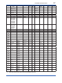
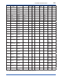
Address Map....................................................................................................... 5-4
5.7.1
Address Map (Basic Information)....................................................... 5-5
5.7.2
Address Map (Detail Information)....................................................... 5-6
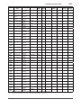
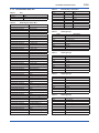
5.7.3 Enumeration table list....................................................................... 5-14
Modbus Communication Troubleshooting............................................ 6-1
Revision Information................................................................................................i
IM 01C25R05-01EN
1.
1-1
<1. Introduction>
Introduction
Thank you for purchasing the DPharp EJX
multivariable transmitter.
EJX multivariable transmitters are precisely
calibrated at the factory before shipment.
To ensure both safety and efficiency, please
read this manual carefully before operating the
instrument.
This manual describes the Modbus protocol
communication functions of the EJX multivariable
transmitter and explains how to set the parameters
for EJX multivariable transmitters.
For information on the installation, wiring, and
maintenance of EJX multivariable transmitters,
please refer to the user’s manual.
EJX910A / EJX930A
IM 01C25R01-01E
Regarding This Manual
• This manual should be provided to the end
user.
• The contents of this manual are subject to
change without prior notice.
• All rights reserved. No part of this manual may
be reproduced in any form without Yokogawa’s
written permission.
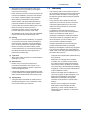
• The following safety symbols are used in this
manual:
WARNING
Indicates a potentially hazardous situation which,
if not avoided, could result in death or serious
injury.
CAUTION
Indicates a potentially hazardous situation which,
if not avoided, may result in minor or moderate
injury. It may also be used to alert against unsafe
practices.
IMPORTANT
Indicates that operating the hardware or software
in this manner may damage it or lead to system
failure.
NOTE
• Yokogawa makes no warranty of any kind with
regard to this manual, including, but not limited
to, implied warranty of merchantability and
fitness for a particular purpose.
Draws attention to information essential for
understanding the operation and features.
• If any question arises or errors are found, or if
any information is missing from this manual,
please inform the nearest Yokogawa sales
office.
1.1 Safe Use of This Product
• The specifications covered by this manual are
limited to those for the standard type under the
specified model number break-down and do not
cover custom-made instruments.
• Please note that changes in the specifications,
construction, or component parts of the
instrument may not immediately be reflected
in this manual at the time of change, provided
that postponement of revisions will not cause
difficulty to the user from a functional or
performance standpoint.
For the safety of the operator and to protect the
instrument and the system, please be sure to follow
this manual’s safety instructions when handling this
instrument. If these instructions are not heeded,
the protection provided by this instrument may be
impaired. In this case, Yokogawa cannot guarantee
that the instrument can be safely operated. Please
pay special attention to the following points:
(a) Installation
• This instrument may only be installed by an
engineer or technician who has an expert
knowledge of this device. Operators are not
allowed to carry out installation unless they
meet this condition.
IM 01C25R05-01EN
• With high process temperatures, care must
be taken not to burn yourself by touching the
instrument or its casing.
• Never loosen the process connector nuts when the
instrument is installed in a process. This can lead
to a sudden, explosive release of process fluids.
• When draining condensate from the pressure
detector section, take appropriate precautions to
prevent the inhalation of harmful vapors and the
contact of toxic process fluids with the skin or eyes.
• When removing the instrument from a
hazardous process, avoid contact with the
process fluid and the interior of the meter.
• All installation shall comply with local installation
requirements and the local electrical code.
(b) Wiring
• The instrument must be installed by an engineer
or technician who has an expert knowledge of
this instrument. Operators are not permitted to
carry out wiring unless they meet this condition.
• Before connecting the power cables, please
confirm that there is no current flowing through
the cables and that the power supply to the
instrument is switched off.
(c) Operation
• Wait 10 min. after the power is turned off before
opening the covers.
(d) Maintenance
• Please carry out only the maintenance
procedures described in this manual. If you
require further assistance, please contact the
nearest Yokogawa office.
• Care should be taken to prevent the build up of dust
or other materials on the display glass and the name
plate. To clean these surfaces, use a soft, dry cloth.
(e) Modification
• Yokogawa will not be liable for malfunctions or
damage resulting from any modification made
to this instrument by the customer.
<1. Introduction>
1-2
1.2 Warranty
• The warranty shall cover the period noted on
the quotation presented to the purchaser at the
time of purchase. Problems occurring during
the warranty period shall basically be repaired
free of charge.
• If any problems are experienced with this
instrument, the customer should contact the
Yokogawa representative from which this
instrument was purchased or the nearest
Yokogawa office.
• If a problem arises with this instrument,
please inform us of the nature of the problem
and the circumstances under which it
developed, including the model specification
and serial number. Any diagrams, data and
other information you can include in your
communication will also be helpful.
• The party responsible for the cost of fixing the
problem shall be determined by Yokogawa
following an investigation conducted by Yokogawa.
• The purchaser shall bear the responsibility for
repair costs, even during the warranty period, if
the malfunction is due to:
- Improper and/or inadequate maintenance by
the purchaser.
- Malfunction or damage due to a failure
to handle, use, or store the instrument in
accordance with the design specifications.
- Use of the product in question in a location
not conforming to the standards specified by
Yokogawa, or due to improper maintenance
of the installation location.
- Failure or damage due to modification or
repair by any party except Yokogawa or an
approved representative of Yokogawa.
- Malfunction or damage from improper
relocation of the product in question after
delivery.
- Reason of force majeure such as fires,
earthquakes, storms/floods, thunder/
lightening, or other natural disasters, or
disturbances, riots, warfare, or radioactive
contamination.
IM 01C25R05-01EN
<1. Introduction>
1-3
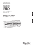
1.3 ATEX Documentation
This is only applicable to the countries in European Union.
GB
DK
SK
CZ
I
LT
E
LV
NL
EST
PL
SF
SLO
P
H
F
BG
D
RO
S
M
GR
IM 01C25R05-01EN
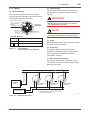
Connection
2.1 Connection with the Modbus
Host
2.1.1 The Hardware Switch
The Hardware switch is located in the CPU Board
Assembly. In order to accessing the switch,
removing the LCD Board is required. Refer to
IM 01C25R01-01E “EJX910A and EJX930A
Multivariable Transmitters” Chapter 9 for detail
instruction.
(2) Baud Rate
By using hardware switch, the baud rate is settable.
The combinations of ON and OFF corresponds to
each baud rate. After turning on the power supply,
the selected baud rate is activated.
CN1
WP
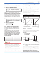
(1) Termination
SW1
The RS-485 bus requires Line Termination near
each of the 2 Ends of the Bus, and not allowed to
place more than 2. By using hardware switch, “the
bus end” is settable. This switch decides “the bus
end” or “the not bus end” on the RS-485 line. If the
hardware switch is ON, “the bus end” is selected. If
it is OFF, the mode is “the not bus end”.
Terminator Switch
ON
O
N
1
2
SW2
O
N
1
2
BAUD
RATE
Baud Rate Switch
F0202.ai
Combinations of “ON” and “OFF”
1 (Upper side)
2 (Lower Side)
OFF
OFF
ON
OFF
OFF
ON
ON
ON
Baud rate [bps]
1200
4800
9600*
19200
*: CN1
GND
2.
2-1
<2. Connection>
Factory default setting.
(3) Write Protect Hardware Switch
There is a slide switch on the CPU assembly board.
Write protection function is activated which disables
all the write possible parameters change through
communication.
OFF
SW2
CN1
Terminator Mode
Bus End
Not Bus End *
*: Position of “ON” and “OFF”
ON: Upper side
OFF: Lower side
GND
F0201.ai
WP
SW1
Factory default setting.
O
N
1
2
SW2
O
N
1
2
BAUD
RATE
Write Protection Switch
Hardware write protection switch (WP)
Write Protection
Switch (1) Position
Write Protection
*:
1
2
O
N
NO*
(Write enabled)
Factory default setting.
1
2
O
N
YES
(Write disabled)
F0203.ai
IM 01C25R05-01EN
2-2
<2. Connection>
2.1.2 Wiring
(2) Power Supply
(1) Terminal Wriring
Fig 2.1 shows the instruction of terminal wiring
(Power supply and 2-wire RS-485). Power must be
supplied after all wrings are finished.
The transmitter requires between 9 and 30 V dc
with less than 2% ripple, and sufficient current
capacity.
IMPORTANT
RTD cable connection
Communication
terminal
connection hooks
Do not connect power wiring to the
MODBUS(RS-485) terminals. It may damage
EJX Multivariable Transmitter.
MODBUS B
SUPPLY +
NOTE
MODBUS A
SUPPLY –
The EJX Multivariable Transmitter power supply
is not electrically isolated from the RS-485 bus.
Terminal Wiring
SUPPLY
+ Power supply terminals
–
A
MODBUS B
Modbus communication (RS-485) terminals
Ground terminal
F0204.ai
Figure 2.1
Terminal Wiring
(Power supply and 2-wire RS-485)
(3) Cable
Balanced pairs should be used. AWG 20 or thicker
should be used for over 300 m.
(4) Grounding
Grounding is always required for the proper
operation of transmitters. Refer to IM 01C25R0101E “EJX910A and EJX930A Multivariable
Transmitters” Chapter 7.
(5) Multi drop communication
Up to 32 EJX Multivariable Transmitters can be
connected on RS-485 bus. Refer to Figure 2.2 for
Multi drop connection.
A
RS-485 Bus
EJX Multivariable
Transmitter*
B
–
A
B
SUP
+
EJX Multivariable
Transmitter*
PLY
–
BUS
BUS
+
PLY
MOD
A
B
SUP
MOD
–
MOD
+
PLY
BUS
B
SUP
A
MODBUS
HOST
B
A
EJX Multivariable
Transmitter*
+
Power Supply
–
Figure 2.2
*: RS485 bus termination can be selected
by the hardware switch.
F0205.ai
Multi drop connection
IM 01C25R05-01EN
2-3
<2. Connection>
(6) Connecting RS-485 USB Adaptor to EJX
Multivariable Transmitter
For configuration of EJX Multivariable Transmitter
using DTM on PC, RS-485 USB Adaptor is required
to connect transmitter to PC. Connecting RS-485
USB Adaptor to EJX Multivariable Transmitter is
described using BLACK BOX “SP390A-R2” isolated
RS485 USB Adaptor as an example in Figure 2.3
and Figure 2.4.
RDB(+)
GND
US
SUP
+
MOD
B
USB
TDA(-)
TDB(+)
BLACK BOX RDA(-)
PLY
–
B
2.2 Integral Indicator Display
When Powering On
For models with the integral indicator code “D”, the
display shows all segments in the LCD and
device/communication information sequentially.
All segments display
Model name (3 s)
Communication Protocol (3 s)
Device Revision (3 s)
Slave Address (3 s)
Serial information (3 s)
E.g.:
Baud rate: 9600 [bps]
Data Length: 8 [bit]
Parity: Even
Stop Bit: 1
A
F0206.ai
BLACK BOX
EJX Multivariable
“SP390A-R2” Isolated
Transmitter
RS485 USB Adaptor
RDA(-)
MODBUS A
RDB(+)
MODBUS B
Figure 2.3 RS-485 USB Adaptor connection
1 2 3 4
RS-422
Echo ON
4 Wire
4 Wire
RS-485
Echo OFF
2 Wire
2 Wire
F0208.ai
NOTE
F0207.ai
1 (RS422/RS485)
RS-485
2 (Echo ON/OFF)
Echo OFF
3 (4 Wire/ 2 Wire)
2 Wire
4 (4 Wire/ 2 Wire)
2 Wire
Figure 2.4 RS-485 USB Adaptor Setting
IMPORTANT
Do not connect MODBUS(RS-485) wiring
to Power terminals. It may damage RS-485
adaptor.
LCD display can be set to all segments display
only.
• Procedure to call up the display
[Root Menu] → Detailed setup → Display condition
→ Chg power on info
Show all segments display and
On
device/communication information
display when powering on.
Show all segments display when
Off
powering on.
NOTE
We recommend isolated RS485 USB Adaptor for
connecting PC to EJX Multivariable Transmitter.
IM 01C25R05-01EN
<2. Connection>
2-4
2.3 Set the parameters using
DTM
When configure the parameters using FieldMate,
use the DTM (Device Type Manager) shown in the
Table 2.1.
Table 2.1
DTM
EJX multivariable
transmitters
DTM
Name
Revision
Model
Name
Device Device
Type Revision
EJX910
3.1.1.0*1 EJX910A EJX910
Modbus DTM or later EJX930A (0x0054)
*1:
1
The DTM corresponding to this revision is included in
Yokogawa Modbus DTM Library 1.1 or later.
NOTE
The DTM revision can be confirmed by “DTM
setup”.
Device Files is a Media included in FieldMate.
The user registration site provides Device Files
with the latest update programs.
(URL: https://voc.yokogawa.co.jp/PMK/)
In case update, following operation by “DTM
setup” is required.
• Update DTM catalog
• Assign corresponding DTM to the device
(refer to Table 2.1)
Refer to FieldMate Instruction Manual for detail.
IM 01C25R05-01EN
3.
3-1
<3. Parameter Setting>
Parameter Setting
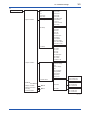
3.1 Menu Tree
■ DTM
Root Menu (Online)
• Device Configuration - Configure/Setup
• Diagnostic
• Process Variable
• Basic setup
• Detailed setup
• Communication setup
• Diag/Service
• Process variables
C
D
B
A
• Slave Address
• Stop Bit
• Parity
• Turnaround Delay Time
F0301-01.ai
A
• Process variables
• Variables
• Pres
• Pres % Range
• SP
• SP % Range
• ET
• ET % Range
• Engr Select
• Engr Disp
• Engr exp
• Engr Unit
• View fld dev vars
• Pres
• SP
• ET
• Cap temp
• Amp temp
• Device Variables and
Status
• Pres
• Pres Data Quality
• Pres Limit Status
• Pres % Range
• Pres % Range Data Quality
• Pres % Range Limit Status
• SP
• SP Data Quality
• SP Limit Status
• SP % Range
• SP % Range Data Quality
• SP % Range Limit Status
• ET
• ET Data Quality
• ET Limit Status
• ET % Range
• ET % Range Data Quality
• ET % Range Limit Status
F0301-02.ai
IM 01C25R05-01EN
<3. Parameter Setting>
3-2
B
• Diag/Service
• Status
• Status group 1
• Status group 2
• Status group 3
• Status group 4
• Status group 5
• Status group 6
• Status group 7
• Status group 8
• Status group 9
• Status group 10
• Status group 11
• Status Bytes
• Cfg chng count
• Reset cfg chng count
• Auto recover
• Test
• Restart
• Squawk
• Simulate
• Test Auto Release
Time
• Calibration
• Calibration Flag
• Calibration Flag
• Pres sensor trim
• Pres trim
• Clear P trim
• SP sensor trim
• SP trim
• Clear SP trim
• ET sensor trim
• ET trim
• Clear ET trim
• Trim info.
• Trim Who
• Trim Date
• Trim Loc
• Trim Desc
• Error log
• Log1(Latest)
• Log2
• Log3
• Log4(Oldest)
• Error log Clear
F0301-03.ai
C
• Basic setup
• Tag
• Tag
• Long tag
• Units
• Pres Unit
• SP Unit
• ET Unit
• Device information
• Date
• Descriptor
• Message
• Write Protect
• Model
• Others
• Low cut
• Low cut mode
• H/L Swap
F0301-04ai
IM 01C25R05-01EN
3-3
<3. Parameter Setting>
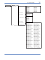
D
• Detailed setup
• Sensors
• Pres
• SP
• ET
• Cap temp
• Amp temp
• Signal condition
• DP Setup
• Output condition
• SP Setup
• SP LRV
• SP URV
• SP Unit
• SP LSL
• SP USL
• SP Min span
• SP Damp
• A/G Select
• SP H/L Select
• Atm. Pres Value
• Auto Atm. Pres
• ET Setup
• ET LRV
• ET URV
• ET Unit
• ET LSL
• ET USL
• ET Min span
• ET Damp
• ET Fixed
• Fixed ET Val
• Process variables
• Pres
• Pres % Range
• SP
• SP % Range
• ET
• ET % Range
• Engr Select
• Engr Disp
• Engr exp
• Engr Unit
• Process Alerts
• Display condition
• Device information
• Test Key
• Flow Simulation
• Pres LRV
• Pres URV
• Pres Unit
• Pres LSL
• Pres USL
• Pres Min span
• Pres Damp
• Low cut
• Low cut mode
• H/L Swap
See E
See F
• Pres Alert
• SP Alert
• ET Alert
• Pres Alert Mode
• Pres Hi Alert Val
• Pres Lo Alert Val
• SP Alert Mode
• SP Hi Alert Val
• SP Lo Alert Val
• ET Alert Mode
• ET Hi Alert Val
• ET Lo Alert Val
F0301-05.ai
IM 01C25R05-01EN
3-4
<3. Parameter Setting>
E
• Detailed setup
• Display condition
• Disp select
• Disp Out 1
• Disp Out 2
• Disp Out 3
• Disp Out 4
• Disp Out 5
• Disp Out 6
• Disp Out 7
• Disp Out 8
• Disp Out 9
• Disp Out 10
• Disp Out 11
• Disp Out 12
• Disp Out 13
• Disp Out 14
• Disp Out 15
• Disp Out 16
• Disp % Reso
• Disp condition
• Engr disp range
• Bar Indicator
• Disp User Value
• Chg power on info
• Pres disp point
• SP disp point
• ET disp point
• Engr Select
• Engr URV
• Engr LRV
• Engr exp
• Engr Unit
• Engr point
• Set Engr Unit
• Disp User Value 1
• Disp User Info 1_1
• Disp User Info 1_2
• Disp User Value Point 1
• Disp User Value 2
• Disp User Info 2_1
• Disp User Info 2_2
• Disp User Value Point 2
• Disp User Value 3
• Disp User Info 3_1
• Disp User Info 3_2
• Disp User Value Point 3
• Disp User Value 4
• Disp User Info 4_1
• Disp User Info 4_2
• Disp User Value Point 4
• Disp User Value 5
• Disp User Info 5_1
• Disp User Info 5_2
• Disp User Value Point 5
• Disp User Value 6
• Disp User Info 6_1
• Disp User Info 6_2
• Disp User Value Point 6
• Disp User Value 7
• Disp User Info 7_1
• Disp User Info 7_2
• Disp User Value Point 7
• Disp User Value 8
• Disp User Info 8_1
• Disp User Info 8_2
• Disp User Value Point 8
• Disp User Value 9
• Disp User Info 9_1
• Disp User Info 9_2
• Disp User Value Point 9
• Disp User Value 10
• Disp User Info 10_1
• Disp User Info 10_2
• Disp User Value Point 10
• Disp User Value 11
• Disp User Info 11_1
• Disp User Info 11_2
• Disp User Value Point 11
• Disp User Value 12
• Disp User Info 12_1
• Disp User Info 12_2
• Disp User Value Point 12
• Disp User Value 13
• Disp User Info 13_1
• Disp User Info 13_2
• Disp User Value Point 13
• Disp User Value 14
• Disp User Info 14_1
• Disp User Info 14_2
• Disp User Value Point 14
• Disp User Value 15
• Disp User Info 15_1
• Disp User Info 15_2
• Disp User Value Point 15
• Disp User Value 16
• Disp User Info 16_1
• Disp User Info 16_2
• Disp User Value Point 16
F0301-06.ai
IM 01C25R05-01EN
3-5
<3. Parameter Setting>
F
• Detailed setup
• Device information
• Field device info
• Sensor information
• Test Key
• Test Key 1
• Test Key 2
• Test Key 3
• Test Key 4
• Flow Simulation
• Flow Simulation
Mode
• Flow Sim Pres Unit
• Flow Sim Pres
• Flow Sim SP Unit
• Flow Sim SP
• Flow Sim Temp Unit
• Flow Sim Temp
• Field device info
• Tag
• Long tag
• User Defined
Number
• Date
• Descriptor
• Message
• MS Code 1
• MS Code 2
• MS Code 3
• Write Protect
• Ext SW
• Option Password
• Wrt protect menu
• Write protect
• Enable wrt 10min
• New password
• Software seal
• Revision #s
• Fld dev rev
• Software rev
• Additional Info
• Style No.
• Serial No.
• Mftr Date
• Extra No.
• Final asmbly num
• Distributor
• PT100 Serial No.
• Country
• Isoltr matl
• Fill fluid
• Gasket matl
• Process Conn matl
• Drain vent matl
• Process Conn type
• RS Isoltr matl
• Process Conn size
• Num of RS
• RS fill fluid
• RS type
F0301-07.ai
IM 01C25R05-01EN
IMPORTANT
After setting and sending data with the
configuration tool, wait 30 seconds before
turning off the transmitter. If it is turned off
too soon, the settings will not be stored in the
transmitter.
3.2 Communication Setup
This section shows how to confirm and change
the EJX Multivariable Transmitter parameters for
Modbus communication. The setting is activated
after powering on except “Turnaround Delay Time”
and “Bus termination”.
• Procedure to call up the display
Item
Slave Address
Stop Bit
Parity
Turnaround Delay
Time
Baud rate
[Hardware Switch]
Bus termination
[Hardware Switch]
3-6
<3. Parameter Setting>
Procedure
[Root Menu]
→ Communication setup
[Root Menu]
→ Communication setup
[Root Menu]
→ Communication setup
[Root Menu]
→ Communication setup
Refer to 2.1.1 The Hardware
Switch
Refer to 2.1.1 The Hardware
Switch
(1) Slave Address
EJX Multivariable Transmitter slave address is
set by this parameter in order to identify the slave
device from the Modbus host. This parameter
should not be set as same address from multiple
devices under the multi drop connection. Address
can be selected from 1* to 247.
(2) Stop Bit
Select Modbus communication Stop Bit from 1bit*/
2bit
(3) Parity
Select Modbus communication Parity from none*/
even/odd
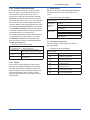
(4) Turnaround Delay Time
The waiting time (ms) between receiving the
request from the host and starting the response
from the device is set by this parameter. The actual
response time of the device is “communication
process time”() + “Turnaround Delay Time”().
When set to 10 ms* which is lower limit, the
response time is only “communication process
time”. Refer Figure 3.1.
*:
Factory default setting.
NOTE
• We recommend that host timeout period is set
larger than 3 s when transmitted data size is
big.
• We recommend that the host communication
period() between receiving the response
from the device and sending the request to
the device is set larger than 100 ms under the
multi drop connection. Refer Figure 3.1.
Master
(Host)
REQUEST
2
REQUEST
1
RESPONSE
1
Slave 1
RESPONSE
2
Slave 2
+
+
F0302.ai
Figure 3.1
IM 01C25R05-01EN
3.3 Basic Setup
3.3.3 Measuring Range
3.3.1 Tag and Device Information
If there are specified when ordering, the desired Tag
No. and device information are set and shipped.
Tag No. and device information can be checked as
follows.
• Procedure to call up the display
Tag
Item
Procedure
[Root Menu] → Basic setup → Tag
→ Tag
[Root Menu] → Basic setup → Tag
→ Long Tag
[Root Menu] → Basic setup → Device
information → Descriptor
[Root Menu] → Basic setup → Device
information → Message
[Root Menu] → Basic setup → Device
information → Date
Long Tag
Descriptor
Message
Date
When the Tag No. and device information are
changed, input them based on the following
limitations.
Tag
Item
Limitations
Up to 8 characters or numbers*1
Long tag
Descriptor
Message
Date
*1: *2: Up to 32 characters or numbers*2
Up to 16 characters or numbers*1
Up to 32 characters or numbers*1
mm/dd/yyyy
- mm: month (2 digits)
- dd: days (2 digits)
- yyyy: years (4 digits)
The characters bounded by the thick line in the following
table can be used.
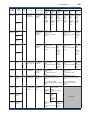
All characters in the following table can be used.
SP
!
"
#
$
%
&
'
(
)
*
+
,
-
.
/
0
1
2
3
4
5
6
7
8
9
:
;
<
=
>
?
@
A
B
C
D
E
F
G
H
I
J
K
L
M
N
O
P
Q
R
S
T
U
V
W
X
Y
Z
[
\
]
^
_
`
a
b
c
d
e
f
g
h
i
j
k
l
m
n
o
p
q
r
s
t
u
v
w
x
y
z
{
|
}
~
*:
3-7
<3. Parameter Setting>
SP shows one-byte space
3.3.2 Process Variables
Process Variables and Status are monitored
by following menus. The status information is
explained in “4. Diagnostics.”
This section shows how to confirm and change
the parameters for measuring range of differential
pressure, static pressure, and external temperature,
and also unit and damping time constant.
These parameters are set at the factory before
shipment if specified at the time of order.
Follow the procedure below to change them.
About the differential pressure, static pressure and
external temperature, settable range are shown
on the parameters of LSL (Lower settable limit),
USL (Upper settable limit) and Min span (Minimum
span). Set the data within the range.
• Procedure to call up the display
Call up and setting of differential pressure related
parameters
[Root Menu] → Detailed setup → Signal condition →
DP Setup →
→ Pres LRV
Lower range value for differential
pressure
→ Pres URV
Upper range value for differential
pressure
→ Pres Unit
Unit for differential pressure
→ Pres Damp Damping time constant for differential
pressure
Call up and setting of static pressure related
parameters
[Root Menu] → Detailed setup → Signal condition →
SP Setup →
→ SP LRV
Lower range value for static pressure
→ SP URV
Upper range value for static pressure
→ SP Unit
Unit for static pressure
→ SP Damp
Damping time constant for static
pressure
Call up and setting of external temperature related
parameters
[Root Menu] → Detailed setup → Signal condition →
ET Setup →
→ ET LRV
Lower range value for external
temperature
→ ET URV
Upper range value for external
temperature
→ ET Unit
Unit for external temperature
→ ET Damp
Damping time constant for external
temperature
• Procedure to call up the display
Item
• Press, SP, ET
• % range of Press, SP, ET
Process Variables and
Status
Procedure
[Root Menu]
[Root Menu] → Process
variables → Process
variables → Device
Variable and Status
IM 01C25R05-01EN
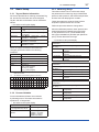
(1) Unit list of differential pressure
mmH2O, mmH2O@68degF, mmHg, Torr, MPa,
kPa , Pa, mbar , bar , gf/cm2, kgf/cm2, inH2O,
inH2O@68degF, inHg, ftH2O, ftH2O@68degF, psi,
atm, hPa
Note that the Yokogawa default setting for the
standard temperature is 4°C (39.2°F). For the units
of mmH2O, inH2O, and ftH2O, the pressure varies
according to the standard temperature definition.
Select the appropriate unit with @68degF when a
standard temperature of 20°C (68°F) is required.
(2) Unit list of static pressure
mmH2O, mmH2O@68degF, mmHg, Torr, MPa,
kPa , Pa, mbar , bar , gf/cm2, kgf/cm2, inH2O,
inH2O@68degF, inHg, ftH2O, ftH2O@68degF, psi,
atm, hPa
(3) Unit list of temperature
degC , degF, Kelvin
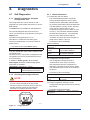
Low cut mode can be used to stabilize the
differential pressure output signal near the zero
point. The Low cut is applied to the differential
pressure used to flow calculation. The low cut point
can be set from 0 to 20% of output. (Hysteresis for
the cut point: ±10% of the cut point )
Follow the procedure below to change the Low cut
mode and Low cut point.
• Procedure to call up the display
[Root Menu] → Basic setup → Others →
→ Low cut
Set from 0 to 20% of output
→ Low cut
Select “On” or “Off”
mode
(%)
50
(%)
50
DP Output
Refer to the subsection 3.3.3 to call up the display.
Select the unit from displayed list as shown below.
3.3.6 Differential Pressure Signal Low Cut
Mode Setup
DP Output
3.3.4 Units
20
0
Input
3.3.5 Damping Time Constant Setup
Any number from 0.00 to 100.00 can be set for
the amplifier damping time constant of process
variables.
Refer to subsection 3.3.3 to call up the display.
Damping time constant is set as shown in the
following table at the factory when the instrument
is shipped, but in case of the option code /CE is
specified, the damping time constant is set as
specified in the order.
Process variables
3-8
<3. Parameter Setting>
Factory default value
Differential pressure
2s
Static pressure
1s
External temperature
1s
50
(%)
For low cut in Off mode
The damping time constant for the amplifier
assembly can be set here. The damping time
constant for the entire transmitter is the sum of
the values for the amplifier assembly and the
capsule assembly.
About the value for the capsule assembly, refer
to the User’s Manual for EJX910/EJX930
(IM 01C25R01-01E) or General Specifications
(GS 01C25R01-01EN, GS 01C25R04-01EN).
0
Input
50
(%)
For low cut in On mode
F0303.ai
Figure 3.2
Low Cut Mode
The low cut point has hysteresis so that the output
around the point is behaved as below figure.
<Example>
Low cut mode: On
Low cut: 20.00%
Low cut point
DP Output
20%
0%
Setting range: 0 to 20%
NOTE
20
Input
2%
2%
Hysteresis
fixed at 10%
of the cut point
F0304.ai
3.3.7 Impulse Line Connection Orientation
Setup
This function reverses the impulse line orientation.
This function is used when the high pressure side
impulse line and the low pressure side impulse line
are connected reverse by mistake.
Follow the procedure below to assign the high
pressure impulse line to the L side of the transmitter.
IM 01C25R05-01EN
• Procedure to call up the display
[Root Menu] → Basic setup → Others →
→ H/L Swap
Select “Normal” or “Reverse”
3.4
3-9
<3. Parameter Setting>
Detailed Setup
3.4.1 Static Pressure Setup
(1) Selection of Gauge pressure and Absolute
pressure
Either the gauge pressure or absolute pressure can
be selected to display on the LCD display.
Absolute pressure is selected when the instrument
is shipped.
3.4.3 Integral Indicator Setup
The following displays are available for integral
indicator. A cycle can be shown by assigning
variables to the parameters at Disp select.
•
•
•
•
•
Input differential pressure
Input static pressure
Input external temperature
User setting of Engineering Unit and Scale
External input values and information (16 items)
Available displays Description and related parameters
Input differential
pressure
(Pres)
P
PRES
• Procedure to call up the display
[Root Menu] → Detailed setup → Signal condition →
SP Setup →
→ A / G Select Select “Gauge” or “Absolute”
Input static pressure
(SP)
SP
3.4.2 External Temperature Fixation Mode
The external temperature can be fixed with this
mode. The parameter setting to enter the Fixation
Mode when the RTD sensor is disconnected is also
possible.
• Procedure to call up the display
[Root Menu] → Detailed setup → Signal condition →
ET Setup →
→ ET Fixed
Select “No”, “Yes” or “FALL BACK”
No: Shows process temperature
value
Yes: Fix the temperature value
FALL BACK: Fix the temperature
value when the RTD
sensor is disconnected.
→ Fixed ET
Set the fixed temperature value
Val
6.178 MPa
Input ext. temperature Indicates values of input external
(ET)
temperature with the indication limits
–99999 to 99999.
T
ET
• Procedure to call up the display
[Root Menu] → Detailed setup → Signal condition →
SP Setup →
→ SP H/L
Select “High” or “Low”
Select
45.6 kPa
Indicates values of input static
pressure with the indication limits
–99999 to 99999.
SP
(2) Selection of pressure side
Either the high or low pressure side of capsule can
be selected to monitor the static pressure.
High pressure side is selected when the instrument
is shipped.
Indicates values of input differential
pressure with the indication limits
–99999 to 99999.
22.95 degC
User setting of
Indicates values depending on the
Engineering Unit and engineering range (Engr LRV and
Scale
Engr URV) with the unit (Engr Unit).
(Engr Disp)
Engr
LRV 0.0
Engr
URV 45.0
Engr
exp x100
Engr
Unit m3/min
Engr
point 1
External input value
and information1
SP
Indicates 16 external input values
and information1. Information1 can
be used e.g. the kind of external
input value.
Disp User Value1: 6.178
Disp User Info1_1: FLOW
External input value
and information2
SP
Indicates 16 external input values
and information2. Information2 can
be used e.g. the unit of external input
value. The external input value during
the information1 continues to display
during the information2 display.
Disp User Info1_2: g/s
F0305.ai
See (a) through (e) for the setting procedures.
IM 01C25R05-01EN
a. Display Selection
At Disp select, select the variable that the
parameter Disp 1 will display on the integral
indicator.
• Procedure to call up the display
Select the engineering unit from the list. Available
units are shown below
kPa
MPa
mbar
bar
psi
psia
mmH2O
mmHg
mmHgA
mmAq
mmWG
Torr
inH2O
inHg
inHgA
[Root Menu] → Detailed setup → Display condition →
Disp select →
→ Disp Out 1
Select desired display from five kinds
of displays shown above.
Set Disp OUT 2 to 16 in the same way if necessary.
“Not used” is also displayed as a selection item.
b. Cyclic Display
Displays can be displayed cyclically in the order of
the parameter number.
c. Display Resolution
User can change the position of decimal point
which is shown on the integral indicator.
• Procedure to call up the Disp % reso display
[Root Menu] → Detailed setup → Display condition →
→ Disp %
Select the decimal point position of %
Reso
Normal: Display one digit below the
decimal point
High Resolution: Display two digits
below the decimal point
• Procedure to call up the Pres disp point, SP
disp point and ET disp point display
[Root Menu] → Detailed setup → Display condition →
Disp Condition →
→ Pres disp
Select the decimal point position of
point
differential pressure (0, 1, 2, 3 or 4)
→ SP disp
Select the decimal point position of
point
static pressure (0, 1, 2, 3 or 4)
→ET disp point Select the decimal point position of
external temperature (0, 1, 2, 3 or 4)
d. User Setting of Engineering Unit and Scale
Engr disp range parameters allow the engineering
unit and scale to be displayed. At Set Engr Unit,
the following engineering units can be selected from
a list.
• Procedure to call up the display
[Root Menu] → Detailed setup → Display condition →
Engr disp range
→ Set Engr
Select the engineering unit
Unit
→ Engr LRV
Lower range value
→ Engr URV
Upper range value
→ Engr exp
Exponents for user scale display
→ Engr point
Decimal point position for user scale
display
→ Engr unit
Confirm and set unit
→ Engr Select Select the target of Engineering unit
3-10
<3. Parameter Setting>
ftH2O
gf/cm2
kgf/cm2
kg/cm2G
kg/cm2A
atm
kg/h
t/h
m3/h
m3/min
l/h
l/min
kl/h
kl/min
Nl/h
Nl/min
Nm3/h
Nm3/min
ACFH
ACFM
CFH
SCFM
GPH
GPM
m
mm
in
ft
kg/m3
g/cm3
At Engr Unit parameter, user can confirm and set
your own unit also.
Up to eight alphanumeric characters, spaces or one
slashe (/) can be input at Engr Unit; only the first six
are displayed on the integral indicator.
• Procedure to call up the display
[Root Menu] → Detailed setup → Display condition →
Engr disp range →
→ Engr Unit
Set your own unit
Note that following symbols are not available:
# % & < > . * : + - , ’ ( )
The integral indicator shows “-- -- -- -- -- --” when
these symbols or more than two slashes are
entered.
e. External input values and information
16 external input values corresponds to “Disp User
Value 1-16” selection lists and they can be selected
from 16 integral indicator display “Disp Out 1-16”
parameters. Regarding the Procedure to call up the
display, refer to “a. Display Selection”.
External input value can be set to floating variable
parameter “Disp User Value 1-16” parameters
and external input information1 can be set to 8
characters variable “Disp User Info 1_1-16_1”
parameters.
External input information2 can be set into 8
characters variable “Disp User Info 1_2-16_2.”
User can change the position of decimal point
which is shown on the integral indicator by “Disp
User Value Point 1-16” parameters.
IM 01C25R05-01EN
• Procedure to call up the display
[Root Menu] →Detailed setup → Display condition
→Disp User Value
→ Disp User Value External input value (16 items)
1-16
→ Disp User Info
External input information1*
1_1-16_1
e.g. the kind of external input
value (16 items)
→ Disp User Info
External input information2*
1_2-16_2
e.g. the unit of external input
value (16 items)
→ Disp User Value The position of decimal point is
Point 1-16
selected from the list.
• Integer
• 1 Down to 1 place of decimals
• 2 Down to 2 places of
decimals
• 3 Down to 3 places of
decimals
• 4 Down to 4 places of
decimals
*: The characters which can be displayed are:
• Alphanumeric (upper case and lower case)
• Space
• - (minus)
• . (piriod)
• / (slash)
The displayed character length is
• 6 characters without “.” or “/”
• 7 characters if one “.” or “/” is included.
<3. Parameter Setting>
Also, you can manually perform the trimming
procedure with Manual, Lower Pt and Manual,
Upper Pt.
The full sensor trim is a two-point adjustment,
and the lower point adjustment should always be
performed before the upper point adjustment in
order to maintain the pitch between the zero and
100% points within the calibration range.
In the manual method, the reference pressure
should also be applied to the transmitter at both
the lower and upper points. Without the reference
pressure, Manual, Lower Pt and Manual, Upper
Pt may not represent the correct value for each
adjustment point.
(1) Auto Sensor Trim
Applying reference pressure of 0% and 100% of the
measurement range to the transmitter, adjust the
lower and upper points automatically.
• Procedure to call up the display
[Root Menu] → Diag/Service → Calibration → Pres
sensor trim → Pres trim →
→ Auto, Lower Pt Auto trim for 0% point
→ Auto, Upper Pt Auto trim for 100% point
3.4.4 Sensor Trim
EJX multivariable transmitter is factory
characterized. Factory characterization is the
process of comparing a known pressure input with
the output of each transmitter sensor module over
the entire pressure and temperature operating
range. During the characterization process, this
comparison information is stored in the transmitter
EEPROM. In operation, the transmitter uses this
factory-stored curve to produce a process variable
output (PV), in engineering units, dependent on the
pressure input.
The sensor trim procedure allows you to adjust
for local conditions, changing how the transmitter
calculates process variables. There are two ways
to trim the sensor: a zero trim and a full sensor trim.
A zero trim is a one-point adjustment typically used
to compensate for mounting position effects or
zero shifts caused by static pressure. A full sensor
trim is a two-point process, in which two accurate
end-point pressures are applied (equal to or greater
than the range values), and all output is linearized
between them.
Full Sensor Trim—Auto Trim and Manual Trim Full sensor trim is carried out by performing Auto,
Lower Pt followed by Auto, Upper Pt.
3-11
(2) Manual Sensor Trim
Using the example below, follow the steps to
perform the full sensor trim by manually. The Pres
LTD (Manual, Lower Pt) and Pres UTD (Manual,
Upper Pt) represent the previously adjusted values
Example: For the range of 1000 to 3000 mmH2O
Pres LTD (Manual, Lower Pt) = −4.0 mmH2O
Pres UTD (Manual, Upper Pt) = −3.0 mmH2O
<1>Call up the Manual, Lower Pt.
• Procedure to call up the display
[Root Menu] → Diag/Service → Calibration → Pres
sensor trim → Pres trim →
→ Manual, Lower Manual trim for 0% point
Pt
→ Manual, Upper Manual trim for 100% point
Pt
<2> S
uppose that a standard pressure of 1000
mmH2O is applied and the value of the “Pres
for trim” is 994.0. Correct for this output error
of 6 mmH2O by adding 6 mmH2O to Pres LTD
(Manual, Lower Pt).
−4.0+6.0=+2.0
IM 01C25R05-01EN
3-12
<3. Parameter Setting>
<3> Enter the correction value of “2” to the Pres
LTD (Manual, Lower Pt).
• Procedure to call up the display for differential
pressure
<4> Call up the Pres UTD (Manual, Upper Pt).
[Root Menu] → Diag/Service → Calibration → Pres
Sensor trim → Clear P trim → Execute
<5> S
uppose that a standard pressure of 3000
mmH2O is applied and the value of the Pres for
trim is 3015.0. Firstly, obtain the slope error for
the span as follows;
Slope Error =
=
Applied Pressure Value−Value of Pres for Trim
Applied Pressure Value
3000−3015
3000
× (URV−LRV)
× (3000−1000) = −10
Then correct for this slope error of −10 by adding
−10 to Pres UTD (Manual, Upper Pt).
−3.0+(−10.0)=−13.0
<6> Enter the correction value of “−13” to the Pres
UTD (Manual, Upper Pt).
(3) Sensor Trim for Static Pressure or External
Temperature
For the EJX multivariable transmitter, full sensor
trim of the static pressure or external temperature is
performed in the same way as with the differential
pressure.
• Procedure to call up the display for static
pressure
[Root Menu] → Diag/Service → Calibration → SP
sensor trim → SP trim →
→ Auto, Lower Pt
Auto trim for 0% point
→ Auto, Upper Pt
Auto trim for 100% point
→ Manual, Lower Pt Manual trim for 0% point
→ Manual, Upper Pt Manual trim for 100% point
• Procedure to call up the display for external
temperature
[Root Menu] → Diag/Service → Calibration → ET
Sensor trim → ET trim →
→ Auto, Lower Pt
Auto trim for 0% point
→ Auto, Upper Pt
Auto trim for 100% point
→ Manual, Lower Pt Manual trim for 0% point
→ Manual, Upper Pt Manual trim for 100% point
(4) Reset Trim Adjistment to Factory Setting
• Procedure to call up the display for static
pressure
[Root Menu] → Diag/Service → Calibration → SP
Sensor trim → Clear SP trim → Execute
• Procedure to call up the display for external
temperature
[Root Menu] → Diag/Service → Calibration → ET
Sensor trim → Clear ET trim → Execute
(5) Calibration flag
When the Calibration Flag parameter is set,
the corresponding status bit in Status Bits and
Status Bytes parameter in Address Map (Basic
Information) will turn ON. The Calibration Flag
parameter is used only for informational use and
does not affect the internal operation of the EJX
Multivariable transmitter. Regarding the Calibration
Flag parameter, refer to 4.1.1.
• Procedure to call up the display
[Root Menu] →Diag/Service → Calibration
→Calibration Flag
→ Calibration Flag Flag the transmitter is in a
calibration State.
3.4.5 External Switch Mode
Follow the procedure below to enable or inhibit zero
point adjustment by means of the zero-adjustment
screw on the transmitter.
This is set to “Disable” when the instrument is
shipped.
To change the mode, follow the procedure below.
• Procedure to call up the display
[Root Menu] → Detailed setup → Device information
→ Field device info → Ext SW
Enabled
Enable the external zero point
adjustment
Disabled
Disable the external zero point
adjustment
The Clear P trim, Clear SP trim and Clear ET trim
commands can reset the trim adjustment to the
initial calibrated values that were set. The amount of
the adjustment performed with the external zeroadjustment screw is returned to the initial setting as
well.
IM 01C25R05-01EN
<3. Parameter Setting>
3-13
3.4.6 Software Write Protection
(1) Alarm Setting
EJX multivariable transmitter configured data is
saved by using a write protection function. The
write protection status is set to “Yes” when 8
alphanumeric characters are entered in the New
password field and transferred to the transmitter.
Select the process variable at Process Alert which
the alarm is set, then set the alert mode for that
value.
When write protection is set to ”Yes,” the transmitter
does not accept all the write possible parameters
changes. When the same eight alphanumeric string
entered in the New password field is also entered
in the Enable wrt 10min field and transferred to the
transmitter, it will be possible to change transmitter
parameters during a 10 minute period.
To change the transmitter from the write protection
”Yes” status back to write protection ”No” status,
use Enable wrt 10min to first release the write
protection function and then enter eight spaces in
the New password field.
• Procedure to call up the display
[Root Menu] → Detailed setup → Device information
→ Field device info → Wrt protect menu →
→ Write Protect
Display current protect mode
(Yes: protected, No: not protected)
→ Enable wrt 10 Release the protect function for 10
min
min.
→ New password Set the new password or change
the password
3.4.7 Alarm
The function is used to display the alarm codes
when the input differential pressure exceeds the
specified value within the calibration range. The
same is available for the input static pressure and
external temperature. Refer to Table 4.1 Alarm
Message Summary for the specific alarm code to
be generated.
• Procedure to call up the display
[Root Menu] → Detailed setup →Output condition →
Process Alerts →
Selection of
→ Pres Alert Mode: Differential
the process
pressure
variable for
→ SP Alert Mode: Static pressure
alarm
→ ET Alert Mode: External
temperature
Selection of
Off: Disable the alert function
alert mode
Hi Al Detect: High side alert detection
Lo Al Detect: Low side alert detection
Hi/Lo Al Detect: High and Low side
alert detection
(2) Threshold Level Setting
Set the threshold of high and low alert value for
alarm generation.
• Procedure to call up the display
[Root Menu] → Detailed setup →Output condition →
Process Alerts →
Parameter
Detail
→ Pres Hi Alert Set the threshold value of upper side
Val
for differential pressure
→ Pres Lo Alert Set the threshold value of lower side
Val
for differential pressure
→ SP Hi Alert
Set the threshold value of upper side
Val
for static pressure
→ SP Lo Alert
Set the threshold value of lower side
Val
for static pressure
→ ET Hi Alert
Set the threshold value of upper side
Val
for external temperature
→ ET Lo Alert
Set the threshold value of lower side
Val
for external temperature
IM 01C25R05-01EN
3-14
<3. Parameter Setting>
3.4.8 Simulation and Squawk
• Procedure to call up the display
NOTE
Flow Simulation Mode, and Device Variable
Simulation Function continue for a given holding
time, then is released automatically. Even if the
configuration tool power supply is turned off or
the communication cable is disconnected, the
test output will continue for that time.
The holding time can be selected from 10 min*,
30 min, 60 min, 3 hour, 6 hour or 12 hour.
*: Default value.
• Procedure to call up the display
[Root Menu] → Diag/Service → Test
→ Test Auto Release Time
(1) Flow Simulation Mode
The pseudo values instead of using actual
measurements of differential pressure, static
pressure, and external temperature can be used.
[Root Menu] → Detailed setup → Flow Simulation →
Off:
–
→ Flow
Simulation ON: DP Differential pressure only
Mode
ON: SP Static pressure only
ON:
DP Differential pressure and
(Select the
SP static pressure
combination
ON: ET External temperature only
of pseudo
variables)
ON: DP Differential pressure and
ET external temperature
ON: SP Static pressure and external
ET temperature
ON: DP Differential pressure, static
SP pressure and external
ET temperature
Check
Differential pressure, static
Flow
pressure, and external
Calc
temperature without
damping
→ Flow Sim
Select the unit for the differential
Pres Unit
pressure
→ Flow Sim
Set the differential pressure value for
Pres
simulation
It is similar about SP and ET.
This is called “flow simulation mode.”
The output value becomes the simulation value and
the LCD continuously displays the simulation value
and alarm (AL.90 SIM) in alternating sequence.
NOTE
The output process value while simulation
can be monitored by LCD and through
communication as follows.
Process value
DP
SP
ET
Output value
Simulation value according to
simulation mode
Simulation value according to
simulation mode
Simulation value according to
simulation mode
F0306.ai
Select the desired simulation mode from the list
below, and set the unit and value.
Following function is reflected while simulation.
Simulation
value
DP/SP/ET
DP
Function
Measuring Range (LRV/URV)
Alarm
Status Output
Damping Time*
Low Cut Mode
*: When “Check Flow Calc” is selected, damping is ignored.
If one of the following alarm occurs while
simulation, all of the output data are held to the
value before alarm occurs.
AL.01 (CAP. ERR)
AL.02 (AMP. ERR)
AL.03 (ET. ERR)
IM 01C25R05-01EN
3-15
<3. Parameter Setting>
(2) Device Variable Simulation Function
(3) Squawk
Using the simulation function, the output signal can
be confirmed by setting any value and status to the
selected device variable.
Call up the parameter and follow the message
shown.
After completing the step 5, the simulation starts.
Integral indicator shows output and alarm (AL.91)
alternately.
This feature can be used to identify the
communicating transmitter by remotely causing
LCD to display the particular pattern as shown in
the Figure 3.3.
“SQUAWK” continues for approximately 10
seconds, then is released automatically.
• Procedure of device variable simulation
Step 1 Call up the
parameter
• Procedure to call up the Squawk display
[Root Menu] → Diag/Service → Test → Squawk
[Root Menu] → Diag/
Service → Test → Simulate
2
Selection of
Device Variable
Select one parameter from
the list below
Off
Pres
SP
ET
3
Setting of Value
Input the simulate value
4
Setting of Data
quality
Select one parameter from
the list below
Bad
Poor accuracy
Manual / Fixed
Good
5
Setting of Limit
status
Select one parameter from
the list below
Not limited
Low limited
High limited
Constant
P
SP
T
F
F0307.ai
Figure 3.3
LCD display for Squawk
NOTE
• All the simulations for differential pressure,
static pressure and external temperature,
are reflected to the output. Accordingly,
LCD display, and communication output are
directly corresponded to the simulate value.
The alarm output is also available according
to the simulate value.
• Damping is applicable for differential
pressure, static pressure, and external
temperature simulation.
IM 01C25R05-01EN
4.
<4. Diagnostics>
4-1
Diagnostics
4.1 Self-Diagnostics
4.1.3 Status Information
4.1.1 Identify Problems by Using the
Configuration Tool
The configuration tool can be used to run selfdiagnostics on a transmitter and check for incorrect
data settings.
The Status menu is available for self-diagnostics.
If the specific diagnostic item is known for the
check, you can directly call up the item by using the
Status menu.
The status is categorized from 1 to 11.
See Table 4.1 to determine the status group.
Show an example below to confirm the status of
Status group 1.
• Procedure to call up the Status display
[Root Menu] → Diag/Service → Status → Status group 1
If no error is detected, check mark is cleared on the
configuration tool.
If there is an error, “check mark” is displayed on the
configuration tool, and a countermeasure for that
error is necessary.
In addition to Status group 1-11 parameters,
Status Bytes parameter in Address Map (Basic
Information) is available.
[Root Menu] →Diag/Service → Status
→ Status Bytes
Status information only mapped in
Address Map (Basic Information)
4.1.2 Checking with Integral Indicator
NOTE
(1) Data quality and Limit status
EJX multivariable transmitter can handle
Device Variables (DP(Pres), SP, ET. Each
variable contains data quality and limit status
for providing useful status about the data value.
The data quality is normally “Good”. However,
in the case of a sensor failure or out of
measurement range, it turns to “Bad” or “Poor
Accuracy”. The limit status indicates whether
the data value is limited (i.e., not responding
to the process). When the limit status is
“Constant”, the value will not be changed. For
detail, refer to Table 4.1 and 4.2.
• Procedure to call up the display
[Device Variables]
[Root Menu] → Process variables → Device variables
and Status →
→ Press Data
Good, Poor Accuracy, Manual/
Quality
Fixed, or Bad is displayed.
→ press Limit
Constant, Low Limit, High Limit, or
Status
Not Limited is displayed.
It is the same about the SP and ET.
(2) Configuration Change Counter
The Configuration Change Counter is
incremented once for every user action
that changes the device’s configuration or
calibration. This value is never reset or written
and maintained even if power is removed from
the device.
• Procedure to call up the display
[Root Menu] → Diag/Service → Status →
→ Cfg chng
count
If an error is detected by running self-diagnostics,
an error number is displayed on the integral
indicator. If there is more than one error, the error
number changes at three-second intervals.
See Table 4.1 regarding the alarm codes.
The configuration change times
are counted.
(3) Reset Configuration Change Counter
Configuration Change Counter can be reset by
this method.
• Procedure to call up the display
[Root Menu] → Diag/Service → Status → Reset Cfg
Chng Count
F0401.ai
Figure 4.1
Integral Indicator
IM 01C25R05-01EN
4-2
<4. Diagnostics>
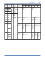
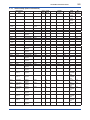
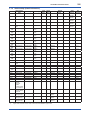
4.2 Alarms and Countermeasures
Table 4.1
Integral
Indicator
Alarm Message Summary
DTM
display
AL.01
P sensor
CAP.ERR error
Status
group
1
CT sensor
error
Cap
EEPROM
error
AL.02
Amp
AMP.ERR EEPROM
error
CPU board
error
ET module
Com error
2
Value and Status (Data Quality and Limit Status)
Cause
Sensor problem. Replace
capsule if the
error recurs
after the
transmitter is
restarted.
Capsule
Replace
temperature
capsule.
sensor problem.
Capsule
EEPROM
problem.
Amplifier
Replace
EEPROM
amplifier.
problem.
Amplifier
problem.
4
ET module
error
AL.03
ET sensor
ET. ERR* error
*:
Countermeasure Differential
Pressure
(DP)
External
temperature
sensor
disconnection.
Static
Pressure
(SP)
External
Temperature
(ET)
DP %
SP %
Value: Hold value
Status: Bad and Constant
(0x30)
Value: Hold value
Status: Bad and Constant
(0x30)
Value: Hold value
Status: Bad and Constant
(0x30)
Value: Hold value
Status: Bad and Constant
(0x30)
Value: Hold value
Status: Bad and Constant
(0x30)
Value: Hold value
Status: Bad and Constant
(0x30)
Value: Hold value
Status: Bad and Constant
(0x30)
Value: Hold value
Status: Bad and Constant
(0x30)
Check external Value: Hold value
temperature
Status: Bad and Constant
sensor.
(0x30)
Value: Hold value
Status: Bad and Constant
(0x30)
Value: Hold value
Status: Bad and Constant
(0x30)
Value: Hold value
Status: Bad and Constant
(0x30)
Value: Hold value
Status: Bad and Constant
(0x30)
Value: Hold value
Status: Bad and Constant
(0x30)
Value: Hold value
Status: Bad and Constant
(0x30)
Value: Hold value
Status: Bad and Constant
(0x30)
ET %
When ET is set as “Fixed” or “Fall back”, this alarm does not occur.
IM 01C25R05-01EN
Integral
Indicator
AL.10
PRESS
4-3
<4. Diagnostics>
DTM
display
P outside
limit
Status
group
3
Value and Status (Data Quality and Limit Status)
Cause
Differential
pressure
is outside
measurement
range limit of
capsule.
AL.11
SP outside
ST.PRSS limit
Static pressure
exceeds limit.
AL.12
CT outside
CAP.TMP limit
Capsule
temperature is
outside range
(–50 to 130°C).
Amplifier
temperature is
outside range
(–50 to 95°C).
External
temperature is
outside range.
AL.13
AT outside
AMP.TMP limit
AL.14
ET outside
EXT.TMP limit
AL.15
OHM
EXT.TMP outside
limit
AL.30
P over
PRS.RNG range
Countermeasure Differential
Pressure
(DP)
Check input
or replace
capsule when
necessary.
Use heat
insulation or
make lagging
to keep
temperature
within range.
Static
Pressure
(SP)
Value:
Measured value
Status:
Poor Accuracy and
Not Limited
(0x40)
Differential
pressure
exceeds
specified range.
AL.31
SP. RNG
SP over
range
Static pressure
exceeds
specified range.
AL.33
ET. RNG
ET over
range
External
temperature
exceeds
specified range.
Check input
and range
setting, and
change them
as needed.
Value:
Measured
value
Status:
Good and
Not Limited
(0xC0)
DP %
SP %
Value:
Measured value
Status:
Poor Accuracy and
Not Limited
(0x40)
ET %
Value:
Measured
value
Status:
Good
and Not
Limited
(0xC0)
Value: Measured value
Status: Good and Not Limited
(0xC0)
Value: Measured value
Status: Good and Not Limited
(0xC0)
Value:
Measured value
Status:
Good and Not Limited
(0xC0)
Value:
Measured value
Status:
Good and Not Limited
(0xC0)
External
temperature
sensor
resistance is out
specification.
4
External
Temperature
(ET)
Value:
Measured value
Status:
Good and Not Limited
(0xC0)
Value:
Measured
value
Status:
Poor
Accuracy
and Not
Limited
(0x40)
Value:
Measured
value
Status:
Poor
Accuracy
and Not
Limited
(0x40)
Value:
Value:
Hold value Measured value
Status:
Status:
Bad and Good and Not Limited
Constant (0xC0)
(0x30)
Value:
Value:
Value:
Measured Hold value Measured
value
Status:
value
Status:
Bad and Status:
Good
Constant Good
and Not
(0x30)
and Not
Limited
Limited
(0xC0)
(0xC0)
Value:
Value:
Measured value
Hold value
Status:
Status:
Good and Not Limited Bad and
(0xC0)
Constant
(0x30)
IM 01C25R05-01EN
Integral
Indicator
DTM
display
Status
group
AL.35
P. HI
AL.36
P. LO
AL.37
SP. HI
AL.38
SP. LO
P high
alarm
P low
alarm
SP high
alarm
SP low
alarm
5
AL.43
ET. HI
ET high
alarm
8
AL.44
ET. LO
ET low
alarm
AL.50
P. LRV
Illegal P
LRV
AL.51
P. URV
Illegal P
URV
AL.52
P. SPN
Illegal P
SPAN
AL.53
P. ADJ
P SPAN
trim err
6
Value and Status (Data Quality and Limit Status)
Cause
Input pressure
exceeds
specified
threshold.
Input static
pressure
exceeds
specified
threshold.
Input external
temperature
exceeds
specified
threshold.
Specified value
is outside of
setting range.
Countermeasure Differential
Pressure
(DP)
Illegal SP
LRV
Illegal SP
URV
Illegal SP
SPAN
Static
Pressure
(SP)
External
Temperature
(ET)
DP %
SP %
ET %
Check input.
Value:
Measured value
Status:
Good and Not Limited
(0xC0)
Value:
Measured value
Status:
Good and Not Limited
(0xC0)
Check settings
and change
them as
needed.
Value:
Measured value
Status:
Good and Not Limited
(0xC0)
Value:
Hold value
Status:
Bad and
Constant
(0x30)
Value:
Measured value
Status:
Good and Not Limited
(0xC0)
Adjust settings
and change
them as
needed.
Value:
Measured
value
Status:
Poor
Accuracy
and Not
Limited
(0x40)
Value:
Measured
value
Status:
Poor
Accuracy
and Not
Limited
(0x40)
Value:
Measured value
Status:
Good and Not Limited
(0xC0)
Check settings
and change
them as
needed.
Value:
Measured value
Status:
Good and Not Limited
(0xC0)
Value:
Measured
value
Status:
Good
and Not
Limited
(0xC0)
Value:
Hold value
Status:
Bad and
Constant
(0x30)
P ZERO
trim err
AL.54
SP. RNG
4-4
<4. Diagnostics>
Value:
Measured value
Status:
Good and Not Limited
(0xC0)
Value:
Measured
value
Status:
Good
and Not
Limited
(0xC0)
IM 01C25R05-01EN
Integral
Indicator
AL.55
SP. ADJ
DTM
display
SP SPAN
trim err
Status
group
7
Value and Status (Data Quality and Limit Status)
Cause
Specified value
is outside of
setting range.
Countermeasure Differential
Pressure
(DP)
Illegal ET
LRV
Static
Pressure
(SP)
External
Temperature
(ET)
Value:
Measured
value
Status:
Poor
Accuracy
and Not
Limited
(0x40)
Value:
Measured
value
Status:
Good and
Not Limited
(0xC0)
DP %
SP %
ET %
Value:
Measured
value
Status:
Good
and Not
Limited
(0xC0)
Value:
Measured
value
Status:
Poor
Accuracy
and Not
Limited
(0x40)
Value:
Measured
value
Status:
Good
and Not
Limited
(0xC0)
Value:
Measured value
Status:
Good and Not Limited
(0xC0)
Value:
Hold value
Status:
Bad and
Constant
(0x30)
Adjust settings
and change
them as
needed.
Value:
Measured
value
Status:
Good
and Not
Limited
(0xC0)
8
Check settings
and change
them as
needed.
Value:
Measured value
Status:
Good and Not Limited
(0xC0)
7
Adjust settings
and change
them as
needed.
Value:
Measured value
Status:
Good and Not Limited
(0xC0)
Value:
Measured
value
Status:
Poor
Accuracy
and Not
Limited
(0x40)
Value:
Measured value
Status:
Good and Not Limited
(0xC0)
Value:
Measured
value
Status:
Poor
Accuracy
and Not
Limited
(0x40)
Value:
Measured value
Status:
Good and Not Limited
(0xC0)
Value:
Hold value
Status:
Good and
Constant
(0xF0)
Value:
Measured value
Status:
Good and Not Limited
(0xC0)
Value:
Hold value
Status:
Good and
Constant
(0xF0)
SP ZERO
trim err
AL.56
ET. RNG
4-5
<4. Diagnostics>
Illegal ET
URV
Illegal ET
SPAN
AL.57
ET. ADJ
ET SPAN
trim err
ET ZERO
trim err
---
ET Fixed
Mode
AL.79
OV.DISP
(None)
AL.90
SIM
Flow
Simulation
mode
5
Under Simulation Check
Mode for flow.
Simulation
Mode.
AL.91
P. SIM
P Simulate
Mode
11
Under Simulation Check
Mode for device Simulation
variables.
Mode
AL.91
SP.SIM
SP
Simulate
Mode
AL.91
ET.SIM
ET
Simulate
Mode
11
Under
Leave from
Temperature Fix Temperature
Mode. PV is ET Fix Mode.
(None) Displayed value Check settings
exceeds limit.
and change
them as
needed.
Value:
Measured value
Status:
Good and Not Limited
(0xC0)
Value: Measured value
Status: Good and Not Limited
(0xC0)
or
Value: Simulation value
Status: Manual/Fixed and Constant
(0xB0)
Value:
Measured value
Status:
Good and Not Limited
(0xC0)
Value and
Status:
Static
Pressure
simulation
value
Value:
Value and
Measured value
Status:
Status:
Temperature
Good and Not Limited simulation
(0xC0)
value
Value:
Measured value
Status:
Good and Not Limited
(0xC0)
Value: Measured value
Status: Good and Not Limited
(0xC0)
or
Value: Simulation value
Status: Manual/Fixed and
Constant
(0xB0)
Value and
Status:
Pressure
simulation
value
unsupported
IM 01C25R05-01EN
Table 4.2
<4. Diagnostics>
Data Quality and Limit Status
Data Quality
Description
Good
The value may be used in
control.
Poor Accuracy
The quality of the value is
less than normal, but the
value may still be useful.
Manual / Fixed
The value is manually
fixed.
Bad
The value is not useful.
Limit Status
Description
Constant
The value cannot be
changed, no matter what
the process does.
Low Limited
The value is out of the
high or low limit.
High Limited
Not Limited
4-6
The value is free to
change.
IM 01C25R05-01EN
5.
5-1
<5. Modbus Communication>
Modbus Communication
5.1 General
5.3 Broadcast
EJX Multivariable transmitter can communicate with
the Modbus host.
Broadcast is a function receiving a command from
all devices connected under multi drop mode.
Table 5.1
(1) Broadcast is executed by setting 0x00 to slave
address.
(2) This message function is executed regardless
of device slave address.
(3) This message is used only for write function.
(4) No response is returned from the slave device.
Modbus specification
Item
Communication
protocol
Flow control
Baud rate
Start bit
Stop bit
Parity bit
Transfer mode
Slave address
Support
function
Max
transmission
frame size
Turnaround
Delay Time
*: Description
2-wire half duplex RS-485 Modbus
None
1200, 4800, 9600*, 19200
1 bit (Fixed)
1 bit*, 2 bits
Odd, Even, None*
RTU (Remote Terminal Unit)
Data length: 8 bits
LSB (Least significant bit sent first)
1* to 247
1: Read Coils
2: Read Discrete Inputs
3: Read Holding Registers
4: Read Input Register
5: Write Single Coil
8: Diagnostic (00: Return Query Data)
16: Write Multiple registers
43: Read device Identification
200 byte
10* to 200 ms
Factory default setting
5.2 Message construction
The message transmitted from host is constructed
as below.
#
Name
1 Slave
address
Size
1 byte
2
1 byte
3
Function
code
Data
4
Error check
0 to
196
bytes
2 byte
Contents
The number host system
distinguish the slave device
(1 to 247)
The function code from host
5.4 Function code
5.4.1 01 (0x01) Read Coils
Specified quantity of Coil contents is read from
Specified Starting Address.
Not corresponding to Broadcast.
Request
Items
Address
Function code
Starting Address
Quantity of coils
CRC
Size [byte]
1
1
2
2
2
Data
1 to 247
0x01
0x0000 to 0xFFFF
-
Size [byte]
1
1
1
N *1
2
Data
1 to 247
0x01
N *1
-
Response
Items
Address
Function code
Byte count
Coil Status *2
CRC
*1:
*2:
N is 1 when quantity of coils is less than or equal to 8.
e.g. When reading address is 1000 – 1007, MSB is 1007
and LSB is1000.
Specify register address,
number or data according to
the function code.
cyclic redundancy check
(CRC-16)
IM 01C25R05-01EN
5-2
<5. Modbus Communication>
5.4.2 02 (0x02) Read Discrete Inputs
5.4.4 04 (0x04) Read Input Registers
Specified quantity of Discrete Inputs contents is
read from Specified Starting Address.
Not corresponding to Broadcast.
Specified quantity of Input Registers contents is
read from Specified Starting Address.
Not corresponding to Broadcast.
Request
Request
Items
Address
Function code
Starting Address
Quantity of Inputs
CRC
Size [byte]
1
1
2
2
2
Data
1 to 247
0x02
0x0000 to 0xFFFF
-
Size [byte]
1
1
1
N *1
2
Data
1 to 247
0x02
N *1
Response
Items
Address
Function code
Byte count
Input Status *2
CRC
*1:
*2:
Items
Address
Function code
Starting Address
Quantity of
Registers
CRC
Items
Address
Function code
Byte count
Register value *2
CRC
*1:
*2:
5.4.3 03 (0x03) Read Holding Registers
Specified quantity of Holding Registers contents is
read from Specified Starting Address.
Not corresponding to Broadcast.
Request
Items
Address
Function code
Starting Address
Quantity of
Registers
CRC
Size [byte]
1
1
2
2
Data
1 to 247
0x03
0x0000 to 0xFFFF
-
2
-
Items
Address
Function code
Byte count
Register value *2
CRC
*1:
*2:
Size [byte]
1
1
1
N*1×2
2
Data
1 to 247
0x03
N*1×2
-
N: The quantity specified by the Quantity of Registers.
Transmitted by the order: Upper- Lower from the specified
Starting Address.
E.g. 10 in FLOAT format, Transmit order is as
0x41200000.
2
-
Size [byte]
1
1
1
N*1×2
2
Data
1 to 247
0x04
N*1×2
-
N: The quantity specified by the Quantity of Registers.
Transmitted by the order: Upper- Lower from the specified
Starting Address.
E.g. 10 in FLOAT format, Transmit order is as
0x41200000.
5.4.5 05 (0x05) Write Single Coil
Write data to Coil of Specified Output Address.
Corresponding to Broadcast.
Request
Items
Address
Function code
Output Address
Output Value
CRC
*1:
Response
Data
1 to 247
0x04
0x0000 to 0xFFFF
-
Response
-
N is 1 when quantity of Discrete Inputs is less than or
equal to 8.
e.g. When reading address is 1000 – 1007, MSB is 1007
and LSB is1000.
Size [byte]
1
1
2
2
Size [byte]
1
1
2
2
2
Data
1 to 247
0x05
0x0000 to 0xFFFF
0x0000 or 0xFF00 *1
-
OFF; 0x0000, ON; 0xFF00
Response
Items
Address
Function code
Output Address
Output Value
CRC
Size [byte]
1
1
2
2
2
Data
1 to 247
0x05
0x0000 to 0xFFFF
0x0000 or 0xFF00
-
IM 01C25R05-01EN
5-3
<5. Modbus Communication>
5.4.6 08 (0x08) Diagnostics
5.5 Response error code
Support only Return Query Data which reply
receiving data.
Not corresponding to Broadcast.
(1) The message format at error
Request
Items
Address
Function code
Sub-function
Data
CRC
*1:
Size [byte]
1
1
2
N
2
Data
1 to 247
0x08
0x0000 *1
Any
-
0x0000; Support only Return Query Data
Response
Items
Address
Function code
Register Address
Register Value
CRC
Size [byte]
1
1
2
N
2
Data
1 to 247
0x08
0x0000
Request Data
-
5.4.7 16 (0x10) Write Multiple registers
Write data to Holding Registers from the Specified
Starting Address to specified quantity.
Corresponding to Broadcast.
Request
Items
Address
Function code
Starting Address
Quantity of
Registers
Byte Count
Registers Value *2
CRC
*1:
*2:
Size [byte]
1
1
2
2
Data
1 to 247
0x10
0x0000 to 0xFFFF
-
1
N*1×2
2
N*1×2
value
-
The device returns the following message without
any operation when incompatibility exists in the
message other than communication error.
Response
Items
Address
Error code
Exception code
Size [byte]
1
1
1
CRC
2
*1:
Data
1 to 247
*1
Refer to following
exception code
-
Error code
Received Function Code(Hex) + 80(Hex) is entered
E.g. When exception is detected in function code 0x01,
Error Code is set to 0x81.
(2) Exception code
Error
Name
code
0x01 ILLEGAL
FUNCTION
0x02 ILLEGAL DATA
ADDRESS
0x03 ILLEGAL DATA
VALUE
0x04 SLAVE DEVICE
FAILURE
Meaning
Function code does not exist
Specified address is out of
range
Specified data is out of quantity
Failure during response
process
(CAP, AMP EEPROM
Failure(AL.01, AL.02))
0x06 SLAVE DEVICE Cannot respond because of
BUSY
under processing
N: The quantity specified by the Quantity of Registers.
Transmitted by the order: Upper- Lower from the specified
Starting Address.
E.g. 10 in FLOAT format, Transmit order is as
0x41200000.
Response
Items
Address
Function code
Starting Address
Quantity of
Registers
CRC
Size [byte]
1
1
2
2
Data
1 to 247
0x10
0x0000 to 0xFFFF
-
2
-
IM 01C25R05-01EN
5-4
<5. Modbus Communication>
5.6 Data format
5.7 Address Map
(1) USIGN INTEGER FORMAT
Address map consists of Basic Information and
Detail Information.
This format is used for integer data.
There are a number of 8 bit values that are stored in
16 bit registers. The 8 bit value is stored in the Least
Significant Byte of the 16 bit register. E.g. 0x24 is
stored as 0x0024.
(2) IEEE 754 FLOATING POINT FORMAT
Floating point values are stored as single precision
IEEE 754 floating point numbers. Since
IEEE 754 floating point numbers are 32 bits long.
Data is stored in the order of MSB (Most significant
byte) first.
E.g. 100.25 is stored as 0x42C88000.
(3) DATE FORMAT
This format is used for date information.
Date: DD, Month: MM, Year: YY is stored as
0x00DDMMYY.
Year: YY means the offset year from Year 1900.
E.g. 30th September 2013 is stored as
0x001E0971.
Category
Address Type
Basic Information Coils
Discrete Inputs
Input Registers /
Holding Registers
Detail Information Coils
Discrete Inputs
Input Registers
Holding Registers
Address
(Decimal)
0003 to 0033
0050 to 0075
0001 to 0454
1001 to 1005
1001 to 1088
1001 to 1316
1001 to 2117
NOTE
• Some data is mapped in both area of Basic
Information and Detail Information.
• Enumeration table list is described
commonly both for Basic Information and
Detail Information.
• The data of Input Register and Holding
Register in Basic Information area can be
read by both function codes.
• In order to access 0001 parameter, set 0000
in communication frame.
• The return value is uncertain when
communicated to address which is not
written in the map.
IM 01C25R05-01EN
5-5
<5. Modbus Communication>
5.7.1 Address Map (Basic Information)
0003
Label used in
DTM
Calibration Flag
Coil
0031
Clear P trim
0032
-
Valid
Range
0x0000,
0xFF00
0x0000,
0xFF00
0x0000,
0xFF00
0x0000,
0xFF00
-
4.1.1
0x0037
0x0054
0x0001
-
1 to 247
3.2
Table 2
-
-
-
3.3.2
3.3.2
3.3.2
4.1.1
R
R
W
-
100.0
-100.0
100.0
kPa
kPa
kPa
-
W
-
0.0
kPa
FLOAT
FLOAT
FLOAT
-
R
R
W
-
25.0
0.0
16.0
MPa
MPa
MPa
FLOAT
-
W
-
0.0
MPa
FLOAT
FLOAT
FLOAT
-
R
R
W
-
850.0
-200.0
850.0
°C
°C
°C
FLOAT
-
W
-
-200.0
°C
FLOAT
-
W
-
-
-
-110 to
110
-110 to
110
-2.5 to
27.5
-2.5 to
27.5
-210 to
860
-210 to
860
With in
adjustable
range
With in
adjustable
range
0 to 100
SINGLE BIT
Char/ Read/
Default
Enum list
Date Write
Value*1
W
Table 1
0
-
Coil
SINGLE BIT
-
W
Table 1
0
-
Clear SP trim
Coil
SINGLE BIT
-
W
Table 1
0
-
0033
Clear ET trim
Coil
SINGLE BIT
-
W
Table 1
0
-
00500075
0001
0002
0003
0016
Status Bits
Discrete Input
-
R
Table 2
0
Distributor
Device Type
Device rev
Slave Address
Input Register
Input Register
Input Register
Holding
Register
Input Register
Input Register
Input Register
Input Register
SINGLE
BIT×26
USIGN8
USIGN8
USIGN8
USIGN8
-
R
R
R
W
-
FLOAT
FLOAT
FLOAT
USIGN32×2
-
R
R
R
R
FLOAT
FLOAT
FLOAT
-
FLOAT
Address
Address Type Access Type
Unit
0401
0403
0405
04070410
0413
0415
0417
Pres
SP
ET
Status Bytes
0419
Pres LRV
0421
0423
0425
SP USL
SP LSL
SP URV
0427
SP LRV
0429
0431
0433
ET USL
ET LSL
ET URV
0435
ET LRV
0437
Pres trim Auto
Lower Pt
Input Register
Input Register
Holding
Register
Holding
Register
Input Register
Input Register
Holding
Register
Holding
Register
Input Register
Input Register
Holding
Register
Holding
Register
Holding
Register
0439
Pres trim Auto
Upper Pt
Holding
Register
FLOAT
-
W
-
-
-
0441
Pres Damp
FLOAT
-
W
-
2.0
s
0443
SP trim Auto
Lower Pt
Holding
Register
Holding
Register
FLOAT
-
W
-
-
-
0445
SP trim Auto
Upper Pt
Holding
Register
FLOAT
-
W
-
-
-
0447
SP Damp
FLOAT
-
W
-
1.0
s
0449
ET trim Auto
Lower Pt
Holding
Register
Holding
Register
FLOAT
-
W
-
-
-
0451
ET trim Auto
Upper Pt
Holding
Register
FLOAT
-
W
-
-
-
0453
ET Damp
Holding
Register
FLOAT
-
W
-
1.0
s
*1:
Pres USL
Pres LSL
Pres URV
IM
Chapter
3.4.4
3.4.4
3.4.4
3.4.4
3.3.3
3.3.3
3.3.3
3.3.3
3.3.3
3.3.3
3.4.4
3.4.4
3.3.5
With in
3.4.4
adjustable
range
With in
3.4.4
adjustable
range
0 to 100
3.3.5
3.4.4
With in
adjustable
range
With in
3.4.4
adjustable
range
0 to 100
3.3.5
This value is factory default of M range measurement span without order specification.
IM 01C25R05-01EN
5-6
<5. Modbus Communication>
5.7.2 Address Map (Detail Information)
1001
Label used in
DTM
Restart
Coil
SINGLE BIT
1002
Squawk
Coil
1003
Error log Clear
1004
1005
Address
10011008
10091016
10171024
10251032
10331040
10411048
10491056
10571064
10651072
10731080
10811088
1001
1002
1003
1004
10061013
1014
1015
1025
1101
1103
1105
1107
1108
1109
1110
1111
*1:
*2:
IM
Chapter
-
Valid
Range
0x0000,
0xFF00
0x0000,
0xFF00
0x0000,
0xFF00
0x0000,
0xFF00
0x0000,
0xFF00
-
-
-
-
4.1.1
Table 8
-
-
-
4.1.1
R
Table 9
-
-
-
4.1.1
-
R
Table 10
-
-
-
4.1.1
-
R
Table 11
-
-
-
4.1.1
-
R
Table 12
-
-
-
4.1.1
-
R
Table 13
-
-
-
4.1.1
-
R
Table 14
-
-
-
4.1.1
-
R
Table 15
-
-
-
4.1.1
-
R
Table 16
-
-
-
4.1.1
-
R
R
-
0x0037
0x0054
-
-
ASCII
R
R
R
-
-
-
-
-
-
4.1.3
3.3.2
3.3.2
3.3.2
4.1.3
-
-
4.1.3
-
-
4.1.1
-
-
4.1.1
-
-
4.1.1
Char/
Date
-
Read/
Default
Enum list
Write
Value*1
W
Table 1
0
-
SINGLE BIT
-
W
Table 1
0
-
Coil
SINGLE BIT
-
W
Table 1
0
-
Auto Atm. Pres
Coil
SINGLE BIT
-
W
Table 1
0
-
Reset cfg chng
count
Status group 1
Coil
SINGLE BIT
-
W
Table 1
0
-
Discrete Input
-
R
Table 6
-
Status group 2
Discrete Input
-
R
Table 7
Status group 3
Discrete Input
-
R
Status group 4
Discrete Input
-
Status group 5
Discrete Input
Status group 6
Discrete Input
Status group 7
Discrete Input
Status group 8
Discrete Input
Status group 9
Discrete Input
Address Type Access Type
Status group 11
Discrete Input
Distributor
Device Type
Code
Fld dev rev
Software rev
Model
Input Register
Input Register
SINGLE
BIT×8
SINGLE
BIT×8
SINGLE
BIT×8
SINGLE
BIT×8
SINGLE
BIT×8
SINGLE
BIT×8
SINGLE
BIT×8
SINGLE
BIT×8
SINGLE
BIT×8
SINGLE
BIT×8
SINGLE
BIT×8
USIGN16
USIGN16
Input Register
Input Register
Input Register
USIGN8
FLOAT
USIGN32×4
Status group 10 Discrete Input
Write protect
Input Register USIGN8
R
Table 31
0x0000
Software seal
Input Register USIGN8
R
Table 32
0x0001
Cfg chng count Input Register USIGN8
R
Pres
Input Register FLOAT
R
SP
Input Register FLOAT
R
ET
Input Register FLOAT
R
Pres Data
Input Register USIGN16
R
Table 5
Quality
Pres Limit
Status
SP Data Quality
SP Limit Status
ET Data Quality Input Register USIGN16
R
Table 5
ET Limit Status
Reserved
Status group 1
Input Register USIGN16
R
Table 6
Status group 2
Table 7
Status group 3
Input Register USIGN16
R
Table 8
Table 9
Status group 4
Status group 5
Input Register USIGN16
R
Table 10
Status group 6
Table 11
This value is factory default of M range measurement span without order specification.
Upper case character can be used. Lower-case is translated to upper case.
Unit
3.4.8
4.1.3
4.1.1
3.4.6
IM 01C25R05-01EN
Address
1112
1113
1114
1121
1123
1125
1127
1128
1129
1131
1133
13011304
13051308
13091312
13131316
10011004
10051012
1013
Label used in
DTM
Status group 7
Status group 8
Status group 9
Status group 10
Status group 11
Reserved
Pres % Range
SP % Range
ET % Range
Pres % Range
Data Quality
Pres % Range
Limit Status
SP % Range
Data Quality
SP % Range
Limit Status
ET % Range
Data Quality
ET % Range
Limit Status
Reserved
Cap temp
Amp temp
Engr Disp
Log1(Latest)
-
-
IM
Chapter
4.1.1
-
-
4.1.1
-
-
4.1.1
-
-
-
3.3.2
3.3.2
3.3.2
4.1.3
Table 5
-
-
-
4.1.3
R
R
R
R
Table 20
-
-
-
-
R
Table 20
-
-
-
USIGN32×2
-
R
Table 20
-
-
-
USIGN32×2
-
R
Table 20
-
-
-
-
-
3.3.1
-
-
3.3.1
-
-
3.3.1
-
-
3.3.1
-
-
-
-
-
-
-
-
-
-
-
-
3.4.6
-
-
3.4.6
-
-
-
-
-
-
-
-
Input Register
USIGN16
-
Input Register
USIGN16
-
Input Register
USIGN16
-
Read/
Default
Enum list
Write
Value*1
R
Table 12
Table 13
R
Table 14
Table 15
R
Table 16
-
Input Register
Input Register
Input Register
Input Register
FLOAT
FLOAT
FLOAT
USIGN16
-
R
R
R
R
Table 5
Input Register
USIGN16
-
R
Input Register
Input Register
Input Register
Input Register
FLOAT
FLOAT
FLOAT
USIGN32×2
-
Log2
Input Register
USIGN32×2
Log3
Input Register
Log4(Oldest)
Input Register
Char/
Date
Address Type Access Type
Holding
USIGN32×2
ASCII*2 W
Register
spaces
Descriptor
Holding
USIGN32×4
ASCII*2 W
Register
0x00010164
Date
Holding
USIGN32
Date
W
Register
1015Long tag
Holding
USIGN32×8
ASCII
W
1030
Register
W
0x0000
1031
User Defined
Holding
USIGN16
Number
Register
spaces
1032Message
Holding
USIGN32×8
ASCII*2 W
1047
Register
1048MS Code 1
Holding
USIGN32×8
ASCII*2 W
1063
Register
1064MS Code 2
Holding
USIGN32×8
ASCII*2 W
1079
Register
1080MS Code 3
Holding
USIGN32×8
ASCII*2 W
1095
Register
spaces
1096Enable wrt
Holding
USIGN32×2
ASCII*2 W
1099 10min
Register
spaces
1100New password Holding
USIGN32×2
ASCII*2 W
1103
Register
1104Option
Holding
USIGN32×8
ASCII
W
spaces
1119
Password
Register
1120
Style No.
Holding
FLOAT
R
Register
1122
Mftr Date
Holding
USIGN32
Date
R
Register
Holding
USIGN32×4
ASCII*2 R
1124Serial No.
Register
1131
*1: This value is factory default of M range measurement span without order specification.
*2: Upper case character can be used. Lower-case is translated to upper case.
Tag
5-7
<5. Modbus Communication>
Valid
Range
Unit
3.3.1
IM 01C25R05-01EN
Address
11321139
1140
Label used in
DTM
Extra No.
5-8
<5. Modbus Communication>
Address Type Access Type
Char/ Read/
Default
Enum list
Date Write
Value*1
spaces
ASCII*2 R
Holding
USIGN32×4
Register
0x00000000
Final asmbly
Holding
USIGN24
W
num
Register
spaces
1142PT100 Serial
Holding
USIGN32×4
ASCII*2 W
1149 No.
Register
1150
Country
Holding
USIGN16
ASCII
W
“JP”
Register
1151
Auto recover
Holding
USIGN8
W
Table 33
0x0001
Register
1152
Isoltr matl
Holding
USIGN8
W
Table 34
Register
1153
Fill fluid
Holding
USIGN8
W
Table 35
Register
1154
Gasket matl
Holding
USIGN8
W
Table 36
Register
1155
Process Conn
Holding
USIGN8
W
Table 37
matl
Register
USIGN8
W
Table 38
1156
Drain vent matl Holding
Register
1157
Process Conn
Holding
USIGN8
W
Table 39
type
Register
1158
RS isoltr matl
Holding
USIGN8
W
Table 40
Register
1159
Process Conn
Holding
USIGN8
W
Table 41
size
Register
1160
Num of RS
Holding
USIGN8
W
Table 42
Register
1161
RS fill fluid
Holding
USIGN8
W
Table 43
Register
1162
RS type
Holding
USIGN8
W
Table 44
Register
1351
Slave Address
Holding
USIGN8
W
0x0001
Register
1352
Stop Bit
Holding
USIGN8
W
Table 55
0x0000
Register
1353
Parity
Holding
USIGN8
W
Table 56
0x0000
Register
1354
Turnaround
Holding
USIGN16
W
0x000A
Delay Time
Register
1401
Pres Unit
Holding
USIGN8
W
Table 60
0x000C
Register
1402
SP Unit
Holding
USIGN8
W
Table 61
0x00ED
Register
1403
ET Unit
Holding
USIGN8
W
Table 62
0x0020
Register
1421
SP H/L Select
Holding
USIGN8
W
Table 70
0x0000
Register
1422
A/G Select
Holding
USIGN8
W
Table 71
0x0001
Register
1423
Atm. Pres Value Holding
FLOAT
W
0.101325
Register
1451
Pres URV
Holding
FLOAT
W
100.0
Register
1453
Pres LRV
Holding
FLOAT
W
0.0
Register
1455
SP URV
Holding
FLOAT
W
16.0
Register
1457
SP LRV
Holding
FLOAT
W
0.0
Register
850.0
1459
ET URV
Holding
FLOAT
W
Register
*1: This value is factory default of M range measurement span without order specification.
*2: Upper case character can be used. Lower-case is translated to upper case.
Valid
Range
Unit
IM
Chapter
-
-
-
-
-
-
-
-
-
0 to 1
-
-
With in
enum list
With in
enum list
With in
enum list
With in
enum list
With in
enum list
With in
enum list
With in
enum list
With in
enum list
With in
enum list
With in
enum list
With in
enum list
1 to 247
3.2
-
0 to 1
3.2
-
0 to 2
3.2
-
3.2
-
0x000A to
0x00C8
With in
enum list
With in
enum list
With in
enum list
0 to 1
3.4.1
-
0 to 1
3.4.1
MPa
-2.5 to
27.5
-110 to
110
-110 to
110
-2.5 to
27.5
-2.5 to
27.5
-210 to
860
-
-
kPa
kPa
MPa
MPa
°C
3.3.4
3.3.4
3.3.4
3.3.3
3.3.3
3.3.3
3.3.3
3.3.3
IM 01C25R05-01EN
1461
Label used in
DTM
ET LRV
1463
Pres USL
1465
Pres LSL
1467
Pres Min span
1469
SP USL
1471
SP LSL
1473
SP Min span
1475
ET USL
1477
ET LSL
1479
ET Min Span
1551
Pres Damp
1553
SP Damp
1555
ET Damp
1601
5-9
<5. Modbus Communication>
FLOAT
-
FLOAT
-
R
-
100.0
kPa
Valid
Range
-210 to
860
-
FLOAT
-
R
-
-100.0
kPa
-
FLOAT
-
R
-
0.5
kPa
-
FLOAT
-
R
-
25.0
MPa
-
FLOAT
-
R
-
0.0
MPa
-
FLOAT
-
R
-
1.0
MPa
-
FLOAT
-
R
-
850.0
°C
-
FLOAT
-
R
-
-200.0
°C
-
FLOAT
-
R
-
10.0
°C
-
FLOAT
-
W
-
2.0
s
0 to 100
3.3.5
FLOAT
-
W
-
1.0
s
0 to 100
3.3.5
FLOAT
-
W
-
1.0
s
0 to 100
3.3.5
Pres trim Auto
Upper Pt
Holding
Register
Holding
Register
Holding
Register
Holding
Register
Holding
Register
Holding
Register
Holding
Register
Holding
Register
Holding
Register
Holding
Register
Holding
Register
Holding
Register
Holding
Register
Holding
Register
Read/
Default
Enum list
Write
Value*1
W
-200.0
FLOAT
-
W
-
-
-
1603
Pres trim Auto
Lower Pt
Holding
Register
FLOAT
-
W
-
-
-
1605
Pres trim
Manual Upper
Pt
Pres trim
Manual Lower
Pt
SP trim Auto
Upper Pt
Holding
Register
FLOAT
-
W
-
-
-
Holding
Register
FLOAT
-
W
-
-
-
Holding
Register
FLOAT
-
W
-
-
-
1611
SP trim Auto
Lower Pt
Holding
Register
FLOAT
-
W
-
-
-
1613
SP trim Manual
Upper Pt
Holding
Register
FLOAT
-
W
-
-
-
1615
SP trim Manual
Lower Pt
Holding
Register
FLOAT
-
W
-
-
-
1617
ET trim Auto
Upper Pt
Holding
Register
FLOAT
-
W
-
-
-
1619
ET trim Auto
Lower Pt
Holding
Register
FLOAT
-
W
-
-
-
1621
ET trim Manual
Upper Pt
Holding
Register
FLOAT
-
W
-
-
-
1623
ET trim Manual
Lower Pt
Holding
Register
FLOAT
-
W
-
-
-
With in
adjustable
range
With in
adjustable
range
With in
adjustable
range
With in
adjustable
range
With in
adjustable
range
With in
adjustable
range
With in
adjustable
range
With in
adjustable
range
With in
adjustable
range
With in
adjustable
range
With in
adjustable
range
With in
adjustable
range
0 to 5
Address
1607
1609
1625
*1:
*2:
Char/
Date
Address Type Access Type
Trim Clear Code Holding
USIGN8
W
Table 72
0x0000
Register
This value is factory default of M range measurement span without order specification.
Upper case character can be used. Lower-case is translated to upper case.
Unit
°C
-
IM
Chapter
3.3.3
3.4.4
3.4.4
3.4.4
3.4.4
3.4.4
3.4.4
3.4.4
3.4.4
3.4.4
3.4.4
3.4.4
IM 01C25R05-01EN
Address
1626
Label used in
DTM
Trim Date
5-10
<5. Modbus Communication>
Address Type Access Type
Char/
Date
Date
Read/
Default
Unit
Enum list
Write
Value*1
0x00010164 W
-
Holding
USIGN32
Register
spaces
1628Trim Desc
Holding
USIGN32×4
ASCII*2 W
1635
Register
spaces
1636Trim Who
Holding
USIGN32×2
ASCII*2 W
1639
Register
spaces
1640Trim Loc
Holding
USIGN32×2
ASCII*2 W
1643
Register
1644
ET Fixed
Holding
USIGN8
W
Table 73
Register
1645
Fixed ET Val
Holding
FLOAT
W
20.0
Register
1647
Ext SW
Holding
USIGN8
W
Table 74
0x0000
Register
1648
H/L Swap
Holding
USIGN8
W
Table 75
0x0000
Register
1649
Low cut
Holding
FLOAT
W
10.0
Register
1651
Low cut mode
Holding
USIGN8
W
Table 76
0x0000
Register
1751
Disp Out 1
Holding
USIGN8
W
Table 80
0x0000
Register
1752
Disp Out 2
Holding
USIGN8
W
Table 81
0x00FA
Register
1753
Disp Out 3
Holding
USIGN8
W
Table 81
0x00FA
Register
1754
Disp Out 4
Holding
USIGN8
W
Table 81
0x00FA
Register
1755
Disp Out 5
Holding
USIGN8
W
Table 81
0x00FA
Register
1756
Disp Out 6
Holding
USIGN8
W
Table 81
0x00FA
Register
1757
Disp Out 7
Holding
USIGN8
W
Table 81
0x00FA
Register
1758
Disp Out 8
Holding
USIGN8
W
Table 81
0x00FA
Register
1759
Disp Out 9
Holding
USIGN8
W
Table 81
0x00FA
Register
W
Table 81
0x00FA
1760
Disp Out 10
Holding
USIGN8
Register
1761
Disp Out 11
Holding
USIGN8
W
Table 81
0x00FA
Register
1762
Disp Out 12
Holding
USIGN8
W
Table 81
0x00FA
Register
1763
Disp Out 13
Holding
USIGN8
W
Table 81
0x00FA
Register
1764
Disp Out 14
Holding
USIGN8
W
Table 81
0x00FA
Register
1765
Disp Out 15
Holding
USIGN8
W
Table 81
0x00FA
Register
1766
Disp Out 16
Holding
USIGN8
W
Table 81
0x00FA
Register
1767
Disp User
Holding
FLOAT
W
0.0
Value 1
Register
1769
Disp User
Holding
FLOAT
W
0.0
Value 2
Register
1771
Disp User
Holding
FLOAT
W
0.0
Value 3
Register
0.0
1773
Disp User
Holding
FLOAT
W
Value 4
Register
1775
Disp User
Holding
FLOAT
W
0.0
Value 5
Register
*1: This value is factory default of M range measurement span without order specification.
*2: Upper case character can be used. Lower-case is translated to upper case.
Valid
Range
IM
Chapter
-
-
-
-
-
-
-
-
0 to 1
3.4.2
°C
3.4.2
-
-273 to
1927
0 to 1
3.4.5
-
0 to 1
3.3.7
%
0 to 20
3.3.6
-
0 to 1
3.3.6
-
3.4.3
-
With in
enum list
With in
enum list
With in
enum list
With in
enum list
With in
enum list
With in
enum list
With in
enum list
With in
enum list
With in
enum list
With in
enum list
With in
enum list
With in
enum list
With in
enum list
With in
enum list
With in
enum list
With in
enum list
-
3.4.3
-
-
3.4.3
-
-
3.4.3
-
-
3.4.3
-
-
3.4.3
-
3.4.3
3.4.3
3.4.3
3.4.3
3.4.3
3.4.3
3.4.3
3.4.3
3.4.3
3.4.3
3.4.3
3.4.3
3.4.3
3.4.3
3.4.3
IM 01C25R05-01EN
5-11
<5. Modbus Communication>
Label used in
Char/ Read/
Default
Address Type Access Type
Enum list
DTM
Date Write
Value*1
1777
Disp User
Holding
FLOAT
W
0.0
Value 6
Register
1779
Disp User
Holding
FLOAT
W
0.0
Value 7
Register
1781
Disp User
Holding
FLOAT
W
0.0
Value 8
Register
1783
Disp User
Holding
FLOAT
W
0.0
Value 9
Register
1785
Disp User Value Holding
FLOAT
W
0.0
10
Register
1787
Disp User Value Holding
FLOAT
W
0.0
11
Register
1789
Disp User Value Holding
FLOAT
W
0.0
12
Register
1791
Disp User Value Holding
FLOAT
W
0.0
13
Register
1793
Disp User Value Holding
FLOAT
W
0.0
14
Register
1795
Disp User Value Holding
FLOAT
W
0.0
15
Register
1797
Disp User Value Holding
FLOAT
W
0.0
16
Register
1799Disp User Info
Holding
USIGN32×2
ASCII
W
“INFO 1 “
1802 1_1
Register
1803Disp User Info
Holding
USIGN32×2
ASCII
W
“ ------ “
1806 1_2
Register
1807Disp User Info
Holding
USIGN32×2
ASCII
W
“INFO 2 “
1810 2_1
Register
1811Disp User Info
Holding
USIGN32×2
ASCII
W
“ ------ “
1814 2_2
Register
1815Disp User Info
Holding
USIGN32×2
ASCII
W
“INFO 3 “
1818 3_1
Register
1819Disp User Info
Holding
USIGN32×2
ASCII
W
“ ------ “
1822 3_2
Register
1823Disp User Info
Holding
USIGN32×2
ASCII
W
“INFO 4 “
1826 4_1
Register
1827Disp User Info
Holding
USIGN32×2
ASCII
W
“ ------ “
1830 4_2
Register
1831Disp User Info
Holding
USIGN32×2
ASCII
W
“INFO 5 “
1834 5_1
Register
1835Disp User Info
Holding
USIGN32×2
ASCII
W
“ ------ “
1838 5_2
Register
1839Disp User Info
Holding
USIGN32×2
ASCII
W
“INFO 6 “
1842 6_1
Register
1843Disp User Info
Holding
USIGN32×2
ASCII
W
“ ------ “
1846 6_2
Register
1847Disp User Info
Holding
USIGN32×2
ASCII
W
“INFO 7 “
1850 7_1
Register
1851Disp User Info
Holding
USIGN32×2
ASCII
W
“ ------ “
1854 7_2
Register
1855Disp User Info
Holding
USIGN32×2
ASCII
W
“INFO 8 “
1858 8_1
Register
1859Disp User Info
Holding
USIGN32×2
ASCII
W
“ ------ “
1862 8_2
Register
1863Disp User Info
Holding
USIGN32×2
ASCII
W
“INFO 9 “
1866 9_1
Register
1867Disp User Info
Holding
USIGN32×2
ASCII
W
“ ------ “
1870 9_2
Register
1871Disp User Info
Holding
USIGN32×2
ASCII
W
“INFO10“
1874 10_1
Register
1875Disp User Info
Holding
USIGN32×2
ASCII
W
“ ------ “
1878 10_2
Register
*1: This value is factory default of M range measurement span without order specification.
*2: Upper case character can be used. Lower-case is translated to upper case.
-
-
IM
Chapter
3.4.3
-
-
3.4.3
-
-
3.4.3
-
-
3.4.3
-
-
3.4.3
-
-
3.4.3
-
-
3.4.3
-
-
3.4.3
-
-
3.4.3
-
-
3.4.3
-
-
3.4.3
-
-
3.4.3
-
-
3.4.3
-
-
3.4.3
-
-
3.4.3
-
-
3.4.3
-
-
3.4.3
-
-
3.4.3
-
-
3.4.3
-
-
3.4.3
-
-
3.4.3
-
-
3.4.3
-
-
3.4.3
-
-
3.4.3
-
-
3.4.3
-
-
3.4.3
-
-
3.4.3
-
-
3.4.3
-
-
3.4.3
-
-
3.4.3
-
-
3.4.3
Address
Valid
Range
Unit
IM 01C25R05-01EN
Address
18791882
18831886
18871890
18911894
18951898
18991902
19031906
19071910
19111914
19151918
19191922
19231926
1927
1928
1929
1930
1931
1932
1933
1934
1935
1936
1937
1938
1939
1940
1941
1942
1943
1944
1945
1946
*1:
*2:
Label used in
DTM
Disp User Info
11_1
Disp User Info
11_2
Disp User Info
12_1
Disp User Info
12_2
Disp User Info
13_1
Disp User Info
13_2
Disp User Info
14_1
Disp User Info
14_2
Disp User Info
15_1
Disp User Info
15_2
Disp User Info
16_1
Disp User Info
16_2
Disp % Reso
5-12
<5. Modbus Communication>
Address Type Access Type
Char/
Date
ASCII
Read/
Default
Enum list
Write
Value*1
W
“INFO11“
Holding
USIGN32×2
Register
Holding
USIGN32×2
ASCII
W
“ ------ “
Register
Holding
USIGN32×2
ASCII
W
“INFO12“
Register
Holding
USIGN32×2
ASCII
W
“ ------ “
Register
Holding
USIGN32×2
ASCII
W
“INFO13“
Register
Holding
USIGN32×2
ASCII
W
“ ------ “
Register
Holding
USIGN32×2
ASCII
W
“INFO14“
Register
W
“ ------ “
Holding
USIGN32×2
ASCII
Register
Holding
USIGN32×2
ASCII
W
“INFO15“
Register
Holding
USIGN32×2
ASCII
W
“ ------ “
Register
Holding
USIGN32×2
ASCII
W
“INFO16“
Register
Holding
USIGN32×2
ASCII
W
“ ------ “
Register
Holding
USIGN8
W
Table 82
0x0000
Register
Bar Indicator
Holding
USIGN8
W
Table 83
0x0001
Register
Pres disp point Holding
USIGN8
W
Table 84
Register
SP disp point
Holding
USIGN8
W
Table 85
Register
ET disp point
Holding
USIGN8
W
Table 86
Register
0x0001
Chg power on
Holding
USIGN8
W
Table 87
info
Register
Disp User Value Holding
USIGN8
W
Table 88
0x0001
Point 1
Register
Disp User Value Holding
USIGN8
W
Table 88
0x0001
Point 2
Register
Disp User Value Holding
USIGN8
W
Table 88
0x0001
Point 3
Register
Disp User Value Holding
USIGN8
W
Table 88
0x0001
Point 4
Register
Disp User Value Holding
USIGN8
W
Table 88
0x0001
Point 5
Register
Disp User Value Holding
USIGN8
W
Table 88
0x0001
Point 6
Register
Disp User Value Holding
USIGN8
W
Table 88
0x0001
Point 7
Register
Disp User Value Holding
USIGN8
W
Table 88
0x0001
Point 8
Register
Disp User Value Holding
USIGN8
W
Table 88
0x0001
Point 9
Register
Disp User Value Holding
USIGN8
W
Table 88
0x0001
Point 10
Register
Disp User Value Holding
USIGN8
W
Table 88
0x0001
Point 11
Register
Disp User Value Holding
USIGN8
W
Table 88
0x0001
Point 12
Register
Disp User Value Holding
USIGN8
W
Table 88
0x0001
Point 13
Register
Disp User Value Holding
USIGN8
W
Table 88
0x0001
Point 14
Register
This value is factory default of M range measurement span without order specification.
Upper case character can be used. Lower-case is translated to upper case.
Valid
Range
-
-
IM
Chapter
3.4.3
-
-
3.4.3
-
-
3.4.3
-
-
3.4.3
-
-
3.4.3
-
-
3.4.3
-
-
3.4.3
-
-
3.4.3
-
-
3.4.3
-
-
3.4.3
-
-
3.4.3
-
-
3.4.3
-
0 to 1
3.4.3
-
0 to 1
-
0 to 4
3.4.3
-
0 to 4
3.4.3
-
0 to 4
3.4.3
-
0 to 1
2.2
-
0 to 4
3.4.3
-
0 to 4
3.4.3
-
0 to 4
3.4.3
-
0 to 4
3.4.3
-
0 to 4
3.4.3
-
0 to 4
3.4.3
-
0 to 4
3.4.3
-
0 to 4
3.4.3
-
0 to 4
3.4.3
-
0 to 4
3.4.3
-
0 to 4
3.4.3
-
0 to 4
3.4.3
-
0 to 4
3.4.3
-
0 to 4
3.4.3
Unit
IM 01C25R05-01EN
Address
1947
1948
2001
Label used in
DTM
Disp User Value
Point 15
Disp User Value
Point 16
Engr Select
20022005
2006
Engr Unit
2007
Engr URV
2009
Engr LRV
2011
Engr point
2012
Set Engr Unit
2051
Pres Alert Mode
2052
Pres Hi Alert Val
2054
Pres Lo Alert Val
2056
SP Alert Mode
2057
SP Hi Alert Val
2059
SP Lo Alert Val
2061
ET Alert Mode
2062
ET Hi Alert Val
2064
ET Lo Alert Val
2101
Flow Simulation
Mode
Flow Sim Pres
Unit
Flow Sim Pres
Engr exp
5-13
<5. Modbus Communication>
Char/
Date
Holding
Register
Holding
Register
Holding
Register
Holding
Register
Holding
Register
Holding
Register
Holding
Register
Holding
Register
Holding
Register
Holding
Register
Holding
Register
Holding
Register
Holding
Register
Holding
Register
Holding
Register
Holding
Register
Holding
Register
Holding
Register
Holding
Register
Holding
Register
Holding
Register
Holding
Register
Holding
Register
Holding
Register
Holding
Register
Holding
Register
Holding
Register
-
Valid
Range
0 to 4
IM
Chapter
3.4.3
USIGN8
-
Read/
Default
Enum list
Write
Value*1
W
Table 88
0x0001
USIGN8
-
W
Table 88
0x0001
-
0 to 4
3.4.3
USIGN8
-
W
Table 89
0x0000
-
0 to 2
3.4.3
USIGN32×2
ASCII
W
-
spaces
-
-
3.4.3
USIGN8
-
W
Table 90
0x0000
-
0 to 3
3.4.3
FLOAT
-
W
-
100.0
-
-
3.4.3
FLOAT
-
W
-
0.0
-
-
3.4.3
USIGN8
-
W
Table 88
0x0001
-
0 to 4
3.4.3
USIGN8
-
W
Table 91
0x0000
-
0 to 45
3.4.3
USIGN8
-
W
Table 92
0x0000
-
0 to 3
3.4.7
FLOAT
-
W
-
100.0
kPa
3.4.7
FLOAT
-
W
-
-100.0
kPa
USIGN8
-
W
Table 92
0x0000
-
-110 to
110
-110 to
110
0 to 3
FLOAT
-
W
-
25.0
MPa
FLOAT
-
W
-
0.0
MPa
USIGN8
-
W
Table 92
0x0000
-
FLOAT
-
W
-
850.0
°C
FLOAT
-
W
-
-200.0
°C
USIGN8
-
W
Table 93
0x0000
-
USIGN8
-
W
Table 60
0x000C
-
FLOAT
-
W
-
0.0
kPa
USIGN8
-
W
Table 61
0x000C
-
FLOAT
-
W
-
0.0
kPa
USIGN8
-
W
Table 62
0x0023
-
FLOAT
-
W
-
273.15
USIGN8
-
W
Table 94
USIGN8
-
W
Table 95
Address Type Access Type
Unit
-2.5 to
27.5
-2.5 to
27.5
0 to 3
3.4.7
3.4.7
3.4.7
3.4.7
3.4.7
K
-200 to
850
-200 to
850
With in
enum list
With in
enum list
-1600 to
1600
With in
enum list
-400000
to 400000
With in
enum list
-
3.4.8
0x0001
-
1 to 3
3.4.8
0x0000
-
0 to 1
3.4.8
Holding
USIGN8
W
Table
0x0000
Register
60, 61, 62
2114
Sim Device
Holding
FLOAT
W
0.0
Variable Value
Register
W
Table 5
0x0000
2116
Sim Device
Holding
USIGN8
Variable Status Register
2117
Test Auto
Holding
USIGN8
W
Table 96
0x0000
Release Time
Register
*1: This value is factory default of M range measurement span without order specification.
*2: Upper case character can be used. Lower-case is translated to upper case.
-
With in
enum list
-
3.4.8
2102
2103
2105
2106
2108
2109
2111
2112
2113
Flow Sim SP
Unit
Flow Sim SP
Flow Sim Temp
Unit
Flow Sim Temp
Sim Device
Variable Code
Sim Write
Device Variable
Code
Sim Unit Code
-
With in
enum list
0 to 5
3.4.7
3.4.7
3.4.8
3.4.8
3.4.8
3.4.8
3.4.8
3.4.8
3.4.8
3.4.8
3.4.8
IM 01C25R05-01EN
5.7.3 Enumeration table list
Table 1
Table 2
Data Quality, Limit Status
Discription
bit7-6
00
01
10
11
Discription
Bad
Poor Accuracy
Manual / Fixed
Good
bit5-4
00
01
10
11
Not Limited
Low Limited
High Limited
Constant
OFF
EXECUTE
Status Bytes, Status Bits
Code
0x80000000 00000000
0x40000000 00000000
0x20000000 00000000
0x10000000 00000000
0x08000000 00000000
0x04000000 00000000
0x02000000 00000000
0x01000000 00000000
0x00800000 00000000
0x00400000 00000000
0x00200000 00000000
0x00100000 00000000
0x00080000 00000000
0x00040000 00000000
0x00020000 00000000
0x00010000 00000000
0x00008000 00000000
0x00004000 00000000
0x00002000 00000000
0x00001000 00000000
0x00000800 00000000
0x00000400 00000000
0x00000200 00000000
0x00000100 00000000
0x00000080 00000000
0x00000040 00000000
0x00000020 00000000
0x00000010 00000000
0x00000008 00000000
0x00000004 00000000
0x00000002 00000000
0x00000001 00000000
0x00000000 80000000
0x00000000 40000000
0x00000000 20000000
0x00000000 10000000
0x00000000 08000000
0x00000000 04000000
0x00000000 02000000
0x00000000 01000000
0x00000000 00800000
0x00000000 00400000
0x00000000 00200000
0x00000000 00100000
0x00000000 00080000
0x00000000 00040000
0x00000000 00020000
0x00000000 00010000
*1: Table 5
Code
Coil
Code
0x0000
0xFF00
5-14
<5. Modbus Communication>
Discription
Calibration Flag
Critical Alarm *1
(None)
P outside limit
(None)
P over range
P over range
(None)
P outside limit
SP outside limit
(None)
SP over range
SP over range
(None)
SP outside limit
(None)
P sensor error *2
ET outside limit
(None)
ET over range
ET over range
(None)
ET outside limit
OHM outside limit
CT outside limit
CT outside limit
(None)
(None)
(None)
(None)
(None)
(None)
(None)
CT sensor error *2
(None)
Cap EEPROM error *2
(None)
(None)
(None)
CPU board error *2
ET sensor error *2
(None)
Amp EEPROM error *2
(None)
ET module error *2
(None)
Write protected
ET module com error *2
Table 6
Code
0x80
0x40
0x20
0x10
0x08
0x04
0x02
0x01
Table 7
Code
0x80
0x40
0x20
0x10
0x08
0x04
0x02
0x01
Table 8
Code
0x80
0x40
0x20
0x10
0x08
0x04
0x02
0x01
Table 9
Code
0x80
0x40
0x20
0x10
0x08
0x04
0x02
0x01
Status group 1
Discription
P sensor error
(None)
CT sensor error
Cap EEPROM error
(None)
(None)
Amp EEPROM error
(None)
Status group 2
Discription
CPU board error
(None)
(None)
(None)
(None)
(None)
(None)
(None)
Status group 3
Discription
P outside limit
SP outside limit
CT outside limit
AT outside limit
(None)
(None)
OHM outside limit
ET outside limit
Status group 4
Discription
P over range
SP over range
(None)
ET over range
ET module com error
(None)
ET sensor error
ET module error
The status indicated as “*2” reflects Critical Alarm bit.
IM 01C25R05-01EN
Table 10
Code
0x80
0x40
0x20
0x10
0x08
0x04
0x02
0x01
Table 11
Code
0x80
0x40
0x20
0x10
0x08
0x04
0x02
0x01
Table 12
Code
0x80
0x40
0x20
0x10
0x08
0x04
0x02
0x01
Table 13
Code
0x80
0x40
0x20
0x10
0x08
0x04
0x02
0x01
5-15
<5. Modbus Communication>
Status group 5
Discription
P high alarm
P low alarm
SP high alarm
SP low alarm
(None)
(None)
(None)
Simulate Mode
Status group 6
Discription
Illegal P LRV
Illegal P URV
Illegal P SPAN
P SPAN trim err
P ZERO trim err
Illegal SP LRV
Illegal SP URV
Illegal SP SPAN
Status group 7
Discription
SP SPAN trim err
SP ZERO trim err
ET SPAN trim err
ET ZERO trim err
(None)
ET Fixed Mode
(None)
(None)
Table 14
Status group 9
Code
0x80
0x40
0x20
0x10
0x08
0x04
0x02
0x01
Discription
(None)
(None)
(None)
(None)
(None)
(None)
(None)
(None)
Table 15
Status group 10
Code
0x80
0x40
0x20
0x10
0x08
0x04
0x02
0x01
Table 16
Code
0x80
0x40
0x20
0x10
0x08
0x04
0x02
0x01
Discription
(None)
(None)
(None)
(None)
(None)
(None)
(None)
(None)
Status group 11
Discription
P Simulate Mode
SP Simulate Mode
(None)
ET Simulate Mode
(None)
(None)
(None)
(None)
Status group 8
Discription
Illegal ET LRV
Illegal ET URV
Illegal ET SPAN
(None)
(None)
(None)
ET high alarm
ET low alarm
IM 01C25R05-01EN
Table 20
5-16
<5. Modbus Communication>
Log1 to 4
Code
0x80000000 00000000
0x40000000 00000000
0x20000000 00000000
0x10000000 00000000
0x08000000 00000000
0x04000000 00000000
0x02000000 00000000
0x01000000 00000000
0x00800000 00000000
0x00400000 00000000
0x00200000 00000000
0x00100000 00000000
0x00080000 00000000
0x00040000 00000000
0x00020000 00000000
0x00010000 00000000
0x00008000 00000000
0x00004000 00000000
0x00002000 00000000
0x00001000 00000000
0x00000800 00000000
0x00000400 00000000
0x00000200 00000000
0x00000100 00000000
0x00000080 00000000
0x00000040 00000000
0x00000020 00000000
0x00000010 00000000
0x00000008 00000000
0x00000004 00000000
0x00000002 00000000
0x00000001 00000000
0x00000000 80000000
0x00000000 40000000
0x00000000 20000000
0x00000000 10000000
0x00000000 08000000
0x00000000 04000000
0x00000000 02000000
0x00000000 01000000
0x00000000 00800000
0x00000000 00400000
0x00000000 00200000
0x00000000 00100000
0x00000000 00080000
0x00000000 00040000
0x00000000 00020000
0x00000000 00010000
0x00000000 00008000
0x00000000 00004000
0x00000000 00002000
0x00000000 00001000
0x00000000 00000800
Discription
P sensor error
(None)
CT sensor error
Cap EEPROM error
(None)
(None)
Amp EEPROM error
(None)
CPU board error
(None)
(None)
(None)
(None)
(None)
(None)
(None)
P outside limit
SP outside limit
CT outside limit
AT outside limit
(None)
(None)
OHM outside limit
ET outside limit
P over range
SP over range
(None)
ET over range
ET module com error
(None)
ET sensor error
ET module error
P high alarm
P low alarm
SP high alarm
SP low alarm
CT high alarm
CT low alarm
Simulate mode
Flow Simulation mode
Illegal P LRV
Illegal P URV
Illegal P SPAN
P SPAN trim err
P ZERO trim err
Illegal SP LRV
Illegal SP URV
Illegal SP SPAN
SP SPAN trim err
SP ZERO trim err
ET SPAN trim err
ET ZERO trim err
(None)
Code
0x00000000 00000400
0x00000000 00000200
0x00000000 00000100
0x00000000 00000080
0x00000000 00000040
0x00000000 00000020
0x00000000 00000010
0x00000000 00000008
0x00000000 00000004
0x00000000 00000002
0x00000000 00000001
Table 31
Code
0
1
Table 32
Discription
ET Fixed Mode
(None)
(None)
Illegal ET LRV
Illegal ET URV
Illegal ET SPAN
(None)
(None)
(None)
ET high alarm
ET low alarm
Write protect
Discription
No (Not write protected)
Yes (Write protected)
Software seal
Code
0
1
Discription
Break
Keep
Table 33
Auto recover
Code
0
1
Discription
Off
On
Table 34
Code
3
4
5
19
252
253
Table 35
Isoltr matl
Discription
Hastelloy C
Monel
Tantalum
Stainless Steel 316L
Unknown
Special
Fill fluid
Code
0
1
252
253
Table 36
Code
10
19
252
253
Discription
Si Oil
F Oil
Unknown
Special
Gasket matl
Discription
PTFE
Stainless Steel 316L
Unknown
Special
IM 01C25R05-01EN
Table 37
Code
0
2
3
4
19
252
253
Table 38
Code
2
3
4
19
251
252
253
Table 39
Process Conn matl
Discription
Carbon Steel
Stainless Steel 316
Hastelloy C
Monel
Stainless Steel 316L
Unknown
Special
Drain vent matl
Discription
Stainless Steel 316
Hastelloy C
Monel
Stainless Steel 316L
None
Unknown
Special
Process Conn type
Code
0
1
2
3
252
253
Code
2
3
4
5
6
19
251
252
253
Discription
Conventional
Remote Seal
Level
Thread
Unknown
Special
Table 40
5-17
<5. Modbus Communication>
RS isoltr matl
Discription
Stainless Steel 316
Hastelloy C
Monel
Tantalum
Titanium
Stainless Steel 316L
None
Unknown
Special
Table 41
Code
0
1
2
3
4
5
6
7
8
9
10
11
12
13
14
15
16
17
18
19
20
21
22
23
24
25
26
27
28
251
252
253
Table 42
Process Conn size
Discription
ANSI3, C150
ANSI3, C300
ANSI3, C600
ANSI4, C150
ANSI4, C300
ANSI2, C150
ANSI2, C300
ANSI2, C600
DIN80, PN10/16
DIN80, PN25/40
DIN80, PN64
DIN100, PN10/16
DIN100, PN25/40
DIN50, PN10/16
DIN50, PN25/40
DIN50, PN64
ANSI 150
ANSI 300
ANSI 600
DIN 10/16
DIN 25
DIN 40
1/2NPT Female
1/4NPT Female
Rc 1/2 Female
1/2NPT Male
G 1/2 Male
M2O * 1.5 Male
R 1/2 Male
None
Unknown
Special
Num of RS
Code
1
2
251
252
Discription
One Seal
Two Seals
None
Unknown
IM 01C25R05-01EN
Table 43
RS fill fluid
Code
RS type
Code
Discription
0
1
2
3
251
252
253
Wafer
Extension
HTV-W
HTV-E
None
Unknown
Special
Table 55
Stop Bit
Code
Table 62
1 bit
2 bit
Table 56
Discription
None
Even
Odd
Table 60
Code
Pres Unit
Discription
inH2O @ 68degF
inHg
ftH2O @ 68degF
mmH2O @ 68degF
mmHg
psi
bar
mbar
gf/cm2
kgf/cm2
Pa
kPa
Torr
atm
MPa
inH2O
mmH2O
ftH2O
hPa
SP Unit
Discription
inH2O @ 68degF
inHg
ftH2O @ 68degF
mmH2O @ 68degF
mmHg
psi
bar
mbar
gf/cm2
kgf/cm2
Pa
kPa
Torr
atm
MPa
inH2O
mmH2O
ftH2O
hPa
ET Unit
Code
32
33
35
Parity
Code
0
1
2
Code
1
2
3
4
5
6
7
8
9
10
11
12
13
14
237
238
239
177
174
Discription
0
1
1
2
3
4
5
6
7
8
9
10
11
12
13
14
237
238
239
177
174
Table 61
Discription
Silicone
SH704
SH705
Ethy Gly/H2O
Prop Gly/H2O
None
Unknown
Special
0
1
2
3
4
251
252
253
Table 44
5-18
<5. Modbus Communication>
Discription
degC
degF
Kelvin
Table 70
SP H/L Select
Code
0
1
Discription
High
Low
Table 71
A/G Select
Code
0
1
Discription
Gauge
Absolute
Table 72
Code
0
1
2
3
4
5
Table 73
Trim Clear Code
Discription
Off (Not Clear)
Pres
SP
(None)
ALL
Ext Temp
ET Fixed
Code
0
1
2
Discription
No
Yes
FALL BACK
IM 01C25R05-01EN
Table 74
Ext SW
Code
0
1
Discription
H/L Swap
Code
0
1
Discription
Normal
Reverse
Table 76
Low cut mode
Code
0
1
Discription
OFF
ON
Table 80
Code
0
1
2
3
4
5
6
7
8
9
10
11
12
13
14
15
16
17
18
19
20
21
22
Table 81
Disabled
Enabled
Table 75
5-19
<5. Modbus Communication>
Disp Out 1
Discription
Pres
SP
ET
Pres % Range
SP % Range
ET % Range
Engr Disp
Disp User Value 1
Disp User Value 2
Disp User Value 3
Disp User Value 4
Disp User Value 5
Disp User Value 6
Disp User Value 7
Disp User Value 8
Disp User Value 9
Disp User Value 10
Disp User Value 11
Disp User Value 12
Disp User Value 13
Disp User Value 14
Disp User Value 15
Disp User Value 16
Code
0
1
2
3
4
5
6
7
8
9
10
11
12
13
14
15
16
17
18
19
20
21
22
250
Table 82
Code
0
1
Table 83
Disp Out 2 to 16
Discription
Pres
SP
ET
Pres % Range
SP % Range
ET % Range
Engr Disp
Disp User Value 1
Disp User Value 2
Disp User Value 3
Disp User Value 4
Disp User Value 5
Disp User Value 6
Disp User Value 7
Disp User Value 8
Disp User Value 9
Disp User Value 10
Disp User Value 11
Disp User Value 12
Disp User Value 13
Disp User Value 14
Disp User Value 15
Disp User Value 16
Not used
Disp % Reso
Discription
Normal
High Resolution
Bar Indicator
Code
0
1
Table 84
Code
0
1
2
3
4
Discription
Off
On
Pres disp point
Discription
Integer
Down to 1 place of decimals
Down to 2 places of decimals
Down to 3 places of decimals
Down to 4 places of decimals
IM 01C25R05-01EN
Table 85
Code
0
1
2
3
4
Table 86
Code
0
1
2
3
4
Table 87
SP disp point
ET disp point
Discription
Integer
Down to 1 place of decimals
Down to 2 places of decimals
Down to 3 places of decimals
Down to 4 places of decimals
Chg power on info
Discription
OFF
ON
Table 88
Code
0
1
2
3
4
Table 89
Code
0
1
2
Table 90
Disp User Value Point/Engr point
Discription
Integer
Down to 1 place of decimals
Down to 2 places of decimals
Down to 3 places of decimals
Down to 4 places of decimals
Engr Select
Discription
Pressure
Static Pressure
External Temperature
Engr exp
Code
0
1
2
3
Table 91
Discription
Integer
Down to 1 place of decimals
Down to 2 places of decimals
Down to 3 places of decimals
Down to 4 places of decimals
Code
0
1
5-20
<5. Modbus Communication>
Discription
x1
x10
x100
x1000
Set Engr Unit
Code
0
1
2
3
4
5
6
7
8
9
10
11
12
13
14
15
16
17
18
19
20
21
22
23
24
25
26
27
28
29
30
31
32
33
34
35
36
37
38
39
40
41
42
43
44
45
Discription
(SPACE)
kPa
MPa
mbar
bar
psi
psia
mmH2O
mmHg
mmHgA
mmAq
mmWG
Torr
inH2O
inHg
inHgA
ftH2O
gf/cm2
kgf/cm2
kg/cm2G
kg/cm2A
atm
kg/h
t/h
m3/h
m3/min
l/h
l/min
kl/h
kl/min
Nl/h
Nl/min
Nm3/h
Nm3/min
ACFH
ACFM
CFH
SCFM
GPH
GPM
m
mm
in
ft
kg/m3
g/cm3
IM 01C25R05-01EN
Table 92
Code
0
1
2
3
Table 93
Code
0
1
2
3
4
5
6
7
15
Table 94
Code
0
1
2
3
Table 95
<5. Modbus Communication>
Alert Mode
Discription
Off
Hi. Al Detect
Lo. Al Detect
Hi/Lo. Al Detect
Flow Simulation Mode
Discription
OFF
ON:DP=ON,SP=OFF,ET=OFF
ON:DP=OFF,SP=ON,ET=OFF
ON:DP=ON,SP=ON,ET=OFF
ON:DP=OFF,SP=OFF,ET=ON
ON:DP=ON,SP=OFF,ET=ON
ON:DP=OFF,SP=ON,ET=ON
ON:DP=ON,SP=ON,ET=ON
Check Flow Calc
Sim Device Variable Code
Discription
(None)
Pressure
Static Pressure
External Temperature
Sim Write Device Variable Code
Code
0
1
Discription
Normal
Fixed Value
Table 96
Test Auto Release Time
Code
0
1
2
3
4
5
5-21
Discription
10min
30min
60min
3hour
6hour
12hour
IM 01C25R05-01EN
6.
6-1
<6. Modbus communication Troubleshooting>
Modbus Communication
Troubleshooting
If any abnormality appears in the Modbus communication, use the troubleshooting lists below to isolate and
remedy the problem. Refer to IM01C25R05-01EN “EJX910A and EJX930A Multivariable Transmitters” for the
transmitter troubleshooting. Since some problems have complex causes, these lists may not identify all. If you
have difficulty isolating or correcting a problem, contact Yokogawa service personnel.
Abnormality
phenomenon
No response from the
device
Priority
1
2
3
4
5
Host timeout
setting
Host
communication
period
6
Modbus
specification
7
Noise
8
Host is not
damaged
9
Device is not
damaged
In the case that
Exception code
ILLEGAL FUNCTION
(0x01) is returned
1
In the case that
Exception code
ILLEGAL DATA
ADDRESS (0x02) is
returned
1
In the case that
Exception code
ILLEGAL DATA VALUE
(0x03) is returned
Item
Device power
Communication
wiring
Modbus
communication
setting
2
1
2
Remedy
Explanation
Confirm if the device power is on.
Confirm if the Modbus communication wiring is correct.
Try switching communication wiring A with B.
Confirm if the Modbus communication setting (Slave
Address, Baud rate, Stop bit, Parity, Data length) is
same as the host and terminator is correctly set in the
RS485 bus.
EJX Multivariable transmitter communication setting
(Slave Address, Baud rate, Stop bit, Parity, Data length)
is confirmed by integral indicator display when powering
on. EJX Multivariable transmitter communication setting
(Baud rate and terminator setting) is confirmed by the
hardware switch.
Confirm if the timeout setting of host is not shorter than
3 seconds.
Confirm if the host communication period between
receiving the response from the device and sending the
request to the device is set larger than 100 ms under the
multi drop connection.
Confirm if the host Modbus communication matches to
Modbus specification.
E.g.
• Sending frame conforms Modbus specification.
• Max transmit frame size is not exceeding 200byte.
• CRC value is correct.
Confirm if the noise is not injected in the signal on
RS485 bus. We recommend isolated RS485 USB
Adaptor for connecting PC to EJX Multivariable
Transmitter.
Confirm the host or RS-485 USB Adaptor is not
damaged by confirming monitor LED. Do not connect
MODBUS (RS-485) wiring to Power terminals. It may
damage RS-485 adaptor.
Contact Yokogawa service personnel and confirm the
EJX Multivariable transmitter is not damaged.
Do not connect power wiring to the MODBUS (RS-485)
terminals. It may damage EJX Multivariable Transmitter.
The EJX Multivariable Transmitter power supply is not
electrically isolated from the RS-485 bus.
Device received unsupported function code.
Confirm if the host Modbus communication matches to
Modbus specification or EJX Multivariable transmitter
Modbus communication specification.
Confirm the host is not sending “Function code 6:
Write Single Register” which is not supported by EJX
Multivariable transmitter.
Device is under “write protect” status. Confirm “write
protect” setting.
Reference
2.1.2 Wiring
2.1.2 Wiring
2.1.1 The Hardware
Switch
2.2 Integral Indicator
Display When
Powering On
3.2 Communication
Setup
3.2 Communication
Setup
5. Modbus
Communication
2.1.2 Wiring
2.1.2 Wiring
2.1.2 Wiring
5. Modbus
Communication
2.1.1 The Hardware
Switch
3.4.6 Software Write
Protection
Device received Read/ Write request on unsupported
5. Modbus
address. Confirm host setting.
Communication
Received data size and quantity value in the frame is not 5. Modbus
same. Confirm host setting.
Communication
Received data other than ON (0xFF00) or OFF (0x0000) 5. Modbus
for writing Coil. Confirm host setting.
Communication
IM 01C25R05-01EN
<6. Modbus communication Troubleshooting>
Abnormality
phenomenon
In the case that
Exception code SLAVE
DEVICE FAILURE
(0x04) is returned
Priority
1
In the case that
1
Exception code SLAVE
DEVICE BUSY (0x06) is
returned
The writing data is
1
ignored
2
Item
Remedy
Explanation
EEPROM in the CPU assembly is damaged. Contact
Yokogawa service personnel for replacing CPU
assembly or device.
Under write processing to EEPROM in the CPU
assembly. Retry after 2 or 3 seconds waitting.
Confirm “write protect” setting.
Confirm if the writing data is outside the limit of Modbus
specification of the device.
6-2
Reference
IM01C25R05-01EN
“EJX910A
and EJX930A
Multivariable
Transmitters” 9.
Maintenance
5. Modbus
Communication
2.1.1 The Hardware
Switch
3.4.6 Software Write
Protection
5. Modbus
Communication
IM 01C25R05-01EN
i
Revision Information
Title
: EJX910A and EJX930A
Multivariable Transmitter Modbus Communication Type
Manual No. : IM 01C25R05-01EN
Edition
Date
Page
1st
Nov. 2013
—
Revised Item
New publication
IM 01C25R05-01EN