1
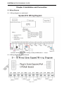
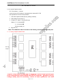
SYSTEM 816 PROGRAMMING GUIDE Thanks for choosing System 816 Multi-Function Alarm Control Panel. We suggest you reading carefully this guide, operating this system strictly on the standard procedure. System 816 is suitable for most circumstances and convenient for using, no matter its appearance, function, or operation. We hope this Guide could answer most of your questions when using the system. Chapter 1 Summarize 1.1 Summarize System 816 takes advanced microprocessor as its core technology. So it has the advantages of high integration, very good stability, flexible function and convenient use. 1.2 Attentions before usage Get approval from local police office before presetting the police phone number as the alarm phone number Ensure the system is in the correct installation, then connect AC power supply with the panel Only suitable for DC 12V 7AH sealed lead rechargeable storage battery, be cautious to connect red positive line with positive terminal (+),and black negative line with negative terminal(-). The incorrect connection will cause damage of main panel. Rechargeable current ≤ 1.5A Avoid metal parts or hand contact to the electronic parts on the circuit when install the lines. Must use 2.7K resistor short unused wired zone Mark wires to avoid miss-connection when using too many wired zones Cut off all AC power supply, battery and telephone line before maintenance Short JP1 when reset main panel The 1.00MM copper-core wire from the keypad to alarm panel is up to 150 meters, 4 keypads can be connected in series Note: After the programming being in progress to the host is finished, please spring with lead plane JP1 place to keep the jumper wire cap down batch away, to prevent others from carrying out operation on your host, and enhance the security of the host. 1.3 Features High speed digital communication, compatible ADEMCO4+2, CID digital communication protocol;Send alarm signal to alarm center. With eight-way output module can be customized output: Linkage output; remote control output (mainly USED IN linked with the monitoring, control home appliances. Lamp, exactly see 4.35) Different programmable settings, such as alarm sounds, zone types, recording, monitoring, remote controlling, telephone number, phone line Check, and etc. Page 1of 15 SYSTEM 816 PROGRAMMING GUIDE Compatible with wired and wireless function 1 group 6 bits primary passwords, 15 groups subsidiary setting passwords are available to improve security; 6 groups of phone number and 3 group alarm center phone number could be set. When the alarm activated, it could repeat dialing the numbers. 8 ARM modes: exit ARM, boundary ARM, single zone ARM, delay ARM, remote ARM, compel ARM , remote ARM and preset time ARM. 6 DISARM modes: single zone DISARM, keypad password DISARM, long distance DISARM, time DISARM, remote setting DISARM, DISARM when connecting alarm. 8 zone modes: instant zone, delay zone, 24 hours zone, boundary zone , fire alarm zone, gas zone, check zone, and BY-PASS zone Remote control function, external monitor, monitoring from long-distance. Built-in voice module, 10~20seconds record, voice alarm function Set the alarm delay time and siren yelp time Search record of emergency Remote controller can be used to set alarm, DIS-ALARM, emergency alarm and other operation. Operate from keypad, easily and convenient. Phone line malfunction indication function: system will alarm when phone line is cut off or short. The alarm dialling is in priority Backup DC 12V 7AH sealed lead rechargeable battery support work when AC power cut off “Watch dog” function, to avoid system down. Remark: Pull out the jumper head in JP1 of the main panel after finishing program for the main panel, which can prevent other person operate the main panel and improve security. 1.4 Configuration Main configuration: Metal box Keypad (LED display User Manual Accessories bag Wireless receiver parts 1pc (transformer and main board inside) 1pc 1pc 1pc phone line, 1 bag terminal resistance, 1 pc antenna 1.5 Main specification Power supply: Stand by consume current: Power: Alarm output current: Output voltage: Wireless receiver frequency: Working temperature: Working Humidity: Weight: Metal box size Keypad size: AC220V+10% ≤100mA <1.5W <650mA, 12V DC12V~15V 315MHZ -10 ~ 55°C 40 ~ 70% 2.5 kgs 255mm×235mm×70mm 159mm×138mm×33mm Page 2 of 16 SYSTEM 816 PROGRAMMING GUIDE Chapter 2 Installation and Connection 2.1 Wiring Diagram 2.1.1 Wiring diagram on main board indicator LED will light on when working normally, Z1-Z8 means 1-8 zone 2.1.2 Wiring diagram of expand board Page 3 of 16 SYSTEM 816 PROGRAMMING GUIDE Z9-Z16 means 9-16 zone 2.1.3 8 zones Expand module Z9-Z16 means 9-16 zone It must connect 2.7K resistors, connecting is the same with Z1-Z8. Set expanded 9-16 wired zones ON/OFF. 1. Insert the expand module (Factory setting: inserted) 2. Start setting mode (see 4.3) 3. Format: 79 + status + F4 (Confirm key) Status: 0 1 9-16 zones OFF 9-16 zones ON (Factory setting: 0) 4. Exit (see 4.4) Note: The reduction can not return to the factory, necessary to manually set. 2.1.4 8-way output module that Together 8-way output module with the keyboard connect to the keyboard port, It can customize the output ROADS and OUTPUT methods (Exactly see 4.35) Linkage widely used in monitoring, control of home appliances, and other Page 4 of 16 SYSTEM 816 PROGRAMMING GUIDE fields. 2.2 Connection of Power supply 2.2.1 Connection of transformer: input AC220V 2 red wires connecting directly Transformer , AC16.5V 2 black wires output terminal will connect AC terminal AC1 and AC2. 2.2.2 DC12V storage battery connection: The black wire should be connected to negative of battery. 2.3 Connection of Wired Detector 2.3.1 Connection of signal wires of wired detector: There are two connection way to avoid destroy, cutoff or short connection, see picture: 1, NORMALLY CLOSED: Connecting a 2.7K EOL resistor in series to the terminal detector of the loop of each zone; connecting the other end of the resistor to the signal terminal of wired detector. One of the signal connector should be soldered to the resistor. The other end of resistor should be connected to the other signal terminal of detector by corresponding signal wire, and then connected to GND port of main board. 2, NOMORMALLY OPENED: Connecting a 2.7K resistor in parallel connection to the terminal detector of the loop of each zone. 2.3.2 Connection of power of Wired Detector: connecting the POSITIVE of wired detector to the AUX port; connecting the negative to the ground wire GND port. 2.3.3 Connecting the unused zones with 2.7K EOL resistor connection, otherwise the corresponding indicator light will keep lighting, so that the ARM cannot be set. Note: Mark wires to avoid miss-connection when using too many wired zones! 2.4 Connection of Siren/Speaker Siren/Speaker Port: The POSITIVE of siren/speaker should be connected to BELL end of alarm panel; the negative should be connected to the ground wire GND. 2.5 Connection of Telephone Line Phone Communication Port: The exterior line should be connected to LIN1, LIN2. TEL1 and TEL2 should be connected to the telephone. Page 5 of 16 SYSTEM 816 PROGRAMMING GUIDE 2.6 Connection of Sound Monitor Sound Monitor Port: The signal line should be connected to MIK, the POSITIVE should be connected to MIK+, and the negative should be connected to ground wire GND. 2.7 Installation of Keypad 2.7.1 Opening of the keypad: use a screwdriver to open the plastic hole of the back cover upside of the keypad. 2.7.2 Connection of the keypad: SEE PICTURE, use a copper core wire to connect the keypad with connector of alarm panel. The wire from the keypad to alarm panel is up to 150 meters, 4 keypads can be connected in series; to avoid destroy of keypad, the anti temper port could be connected to the terminal of alarm panel. 2.7.3 Keypad address: no address jumper means NO. 1 keypad; insert address jumper “1” means NO. 2 keypad; insert address jumper “2” means NO. 3 keypad; insert address jumper “3” means NO. 4 keypad. 2.7.4 Close the cover when the connection is finished. 2.8 Installation when wireless zones only. If you want to use the wireless zones only, connect the wired zones with the ground wire GND by 2.7K resistors in short connection, keep close of the wired zones. Note: Make sure the all the connections are correct before power up the alarm panel. Avoiding any opposite connection, short connection of power line, siren line and detector power line; avoiding short connection of detector power line and signal line! Page 6 of 16 SYSTEM 816 PROGRAMMING GUIDE Chapter 3 System Operation 3.1 System Operation The main usage of the alarm system is to prevent illegal intruder from your home or office, or to get help in emergency. When you are leaving your office or home, make sure all the windows and doors are locked. Set ARM by remote controller or keypad of alarm panel, the system will be in guard status. If any alarm zone is activated, the following circs will happen: 3.1.1 If host has siren linked and the defence zone is in “sound alarm” condition, there will be hooter from siren and beep from keypad on spot. 3.1.2 Alarm panel will send the alarm to control center by dialing the telephone if set to send the alarm to control center. 3.1.3 If telephone number is set, it will dial the preset numbers in turn. after switching telephone receiving alarm control (see 3.7) operation. 3.1.4 Zone LED will keep light on in alarm status till eliminate its alarm memory. 3.2 Operation of Remote Controller Remote Controller : - DIS-ALARM: DIS-ALARM Status - Set ARM: Leaving-taking ARM - BOUNDARY (Home) ARM BOUNDARY Zone Alarm Status - Emergency: Emergency when a Hijack or emergency call DIS-ALARM: Fast press twice “ ” Key of the Remote Controller Note: BOUNDARY ARM will be in effect only when BOUNDARY Zone was set. 3.3 Keypad Panel and Indicator LED Light Parts Name: ①---Function Indicator Light ②---ARM Zone Light ③---Emergency Key ④---Number Key ⑤---Shortcut Key (F1-ARM; F2-Home ARM; F3- Pause; F4-Confirm Key) Page 7 of 16 to a SYSTEM 816 PROGRAMMING GUIDE Specification: ①. Function Indicator Light (Power Supply, Communication, Signal, Status, ARM, Setting): Indicate the working status of the System Function Indicator Light Power Supply Communication Signal Status ARM Setting Display ON OFF ON OFF ON OFF ON OFF ON OFF ON OFF Explanation AC Power Supply Normal AC Power Supply Break Dialing and Sending message Status, the line is busy The line is not in use Signal from Wireless Detector Received Normal Status Keypad Work Normal Keypad Failure EXIT/BOUNDARY/Single Zone ARM No ARM Status Programming Status Normal Status ② ARM Zone Light(1, 2, 3……14, 15, 16): Display the Zone Status Display ON Fast Flash Explanation ARM Activated; Training Status: ready to Train wireless detector Zone Indicate the Zone disarm after Alarm, but the alarm status hasn’t been stopped Slow Flash Wired Zone bad connection, the Circuit is Open or Short ON 1 Second Zones in Effect on ARM Status ③ Emergency Key (A, B, C) 24 hours Alarm Status, can be defined as Fire Alarm, Robbery Alarm, Emergency Call; No indicator, no sound; If telephone preset, it will dial the number when alarm, the communication light will on ④ Number Key (1, 2, 3, 4, 5, 6, 7, 8, 9, *, 0, #): For password and program set use. ⑤ Shortcut Key (F1, F2, F3, F4) Easy to operation with One Key. F1-EXIT ARM; F2--Boundary ARM (Only when boundary Zones Preset); F3-Detector Low Vol. Quirt/Pause; F4-Confirm Key). ⑥ Buzzer Sound; In this operation, different buzzer sound indicates different meaning Sound Explanation Long Sound Remote Control or Keypad operation received Long Sound 1 minute Sound Zone Alarm Short Sound Sound per press the Keypad Short Sound 3 times Invalid Input or Remote Control Operation Short Sound per 3 seconds Delay ARM Started, or Delay Zone Activated, the sound will end till the delay time is over Page 8 of 16 SYSTEM 816 PROGRAMMING GUIDE 3.4 ARM ARM means the system is in arm condition and ready to response the alarm signal by detectors in corresponding defence zone. If arm successfully---- the buzzer send a long beep, the light in corresponding zone is on for 1 sencond, and the ARM indication light is on. If arm failed---- the buzzer send three short beep and ARM indication light is off, and user should check if any defence zone is triggered or in open-circuit condition, or the system is in ARM condition. If there is an ARM Delay, the system will exit the delay after inputs ARM dictate, and short sound every second till delay time is over. It will not send alarm before some zone is activated. 3.4.1 Leaving-Taking ARM; All zones (except Side Road or Screened Zones) start Alarm Status, if any zone activated, the system will take relevant reaction, dial the alarm center, preset telephone number or local police. Operation: Press F1 Key or press “ ” on remote controller to set ARM. 3.4.2 BOUNDARY ARM, also named Home ARM, when a BOUNDARY ARM start alarm status, non-BOUNDARY ARM will not activate alarm 1, Operation: Press F2 Shortcut Key or press “ ”on Remote Controller to set ARM.(Boundary arm see4.9) 3.4.3 Set Single Zone ARM/ DIS- ARM: the specified zone start alarm status, the other zones will not activated alarm Operation: Set single zone ARM: Zone Number(01~16)+F1 Shortcut Key, Set single zone DIS-ARM: Password(6 bites)+Zone Number(01~16)+ F4Shortcut Key, 3.4.4 Fast alarmed set,it can be operated direct without time late Operating: press *+F1 3.4.5 Set compelled ARM: Password + * + F1 Note: Boundary ARM and Single Zone ARM can be set at the same time or turn to EXIT ARM if ARM not stopped. 3.5 Disarm: DIS-ALARM Status 1, Operation: User Password (6 bites)+F4 (Confirm Key) 123456), or press “ ” key on Remote Controller (Factory User Password: 2, Disarm Succeed: ARM Indicate Light off; if the system refuse the dictate, the Buzzer will short sound 3 times, or system has already disarm. Page 9 of 16 SYSTEM 816 PROGRAMMING GUIDE 3.6 Remote Control When System is set as Remote Controllable (See 4.18), (Factory Setting: non-remote control), use a preset phone or mobile phone to remote control the alarm system to ARM, disarm, record or monitor. Ring time when dial the preset phone: (Set in Step 4.19, Factory Setting is 8 times); after connected, Input User Password: after a long sound “Di”, Access to Remote Control Status; 3.6.1 Remote ARM, Disarm In remote control status: input “1” to start ARM Status, if succeed, you will hear a long sound ”Di”, if not succeed, you will hear 3 short sound; input “2” to disarm, if succeed, you will hear a long sound ”Di”, if not succeed, you will hear 3 short sound. 3.6.2 Remote Monitor In remote control status: press “3”, then you can hear the instant sound from the zones; press “8” to return 3.6.3 Remote control to siren In remote control status, press “4” start siren, press “5” exit siren. 3.7 Set Receive Alarm by Telephone; when the alarm connected the phone or mobile phone, user can remote control the system by phone or mobile phone. There are 3 methods as following 3.7.1 Dial-up then pick-up alarm, Press “3” start directly Remote Control Status. 3.7.2 It can also be programmed as: (See 4.21) after connected, say “Hello” to receive recorded sound, after twice record and indicate sound “Du”, input user password to remote control status or program to automatically say “Hello” after; indicate sound “Du” after, enter the user password(see4.20), directly Remote Control Status. 3.7.3 Dial-up then pick-up alarm, press “2” hang up(Host stop dial-up) Remote Control Status: Start control status by using telephone or mobile phone, press “1” to start ARM; press “2” to disarm, (stop dial the following phone number after ARM started): press “3” to start Remote Monitor; press “8” to Return, end monitor; press “7” change recorded sound, press “8” exit; press “4” start siren, press “5” exit siren and return to control status. Note: Remote Control Status is different from the “1”, “2”, “3” of Hang on operation. Page 10 of 16 SYSTEM 816 PROGRAMMING GUIDE 3.8 Record: Record the alarm sound by another preset phone or mobile phone, Differentiate to receive the police sound recording and the dialling mark sound recording 3.8.1 After receiving the warning sound recording: while receiving the warning sound ,used by the state of long-range "7" to amend the methods for recording audio, 7 by telephone or cell phone microphone to record the contents of the need to tell (10-20 seconds). "8" from the recording, according to the "6" player has a good voice recording, hang up to determine the correct. For re-recorded, after playing, according to the "7" was recorded, the operation can be repeated until satisfied with this.3.8.2 dial-up record: 3.8.2 The dialling mark sound recording 1, Keypad Input Status; Installer password (Factory Setting: 666666)+F4 (Confirm Key) Start Set 71+1+F4 Start Remote Control Status; 72+2+F4 Set Ring time as 2 times; * # Exit Set Status 2, Record: Use another preset phone or mobile phone dial the number of alarm system, after connected, input user password (Factory Setting: 123456)+7 Speak what you want to record to telephone or mobile phone, the recorded sound will play automatically after 12 seconds; or press “8” exit recording, press “6” paly the finished recorded sound, then hang -up. If need new record sound, press “8” exit, then press “7” stat new record sound till it’s satisfied. 3, Confirm Record: Dial the phone or mobile phone, after connected, press “1” key on the phone or mobile phone to receive sound, if need revised please repeat above Step 2. 4, After record, keypad input Key) Start Set Status; time as 8 times; installer password (Factory setting: 666666)+F4 (Confirm 71+0+F4 End Remote Control Status; 72+8+F4 Set Ring * # Exit Set Status 3.9 DIS-ALARM: Stop the flashing status of alarm indicator LED light, stop sending messages to alarm center 1, Operation: User password (6bites)+F4 (Confirm Key) Setting: 123456) Or press “ (User Password Factory ” key on the remote controller to DIS-ALARM 2, If succeed, the buzzer will long sound “Di”, the indicator LED light off. 3.10 BY-PASS Zone Checking: Press F1, the zone LED will light on no more than 1 second Page 11 of 16 SYSTEM 816 PROGRAMMING GUIDE Chapter 4 System Settings 4.1 Basic Settings from Factory Name Factory Settings 1. Installer Password 666666 2. First Group User Password 123456 3. Zone Type 0---instant sound alarm zone 4. Play recorded sound automatically 0---inefficacy 5. AC power supply cut-off check 0---no check 6. Keypad line cut-off check 0---no check 7. Keypad anti-disassembly check 0---no check 8. Telephone Remote Control 0---inefficacy 9. Ring Times 0---8 times 10. ARM Delay 0---no delay 11. Telephone Line Check No Check 12. Code ADEMCO 4+2 code 13. Telephone alarm control Input ”1” set, input ”2” stop, input “3” monitor 14. Recorder No recorder 15. Wireless Detector No wireless detector 16. User Number FFFF 17. Alarm Telephone Number No number Note: Function 1 to 12 will resume factory settings after “RESET”. 4.2 Reset 1. Operation; 951753082+F4 (Confirm Key); 2. Status: Reset successfully, the buzzer will sound a long” Di”, all the indicator LED will light on for 1 second. Note: JP1 jumper on the main board must be short connected before this operation. 4.3 Change user Password 1.Change Primary password: Primary password (6 bites) + 08 + F4 (Confirm Key), the setting indicate LED on, input new primary password (6 bites) + F4 (Confirm Key), after the buzzer sound a long “Di”, the indicator LED light off, new primary password is in effect. (Primary password: 123456) 2. Increase Subsidiary Password: Primary password (6 bites) + 08 + F4 (Confirm Key), the setting indicate LED on, input subsidiary password number (2 bites) + F4 (Confirm Key),( subsidiary password number: 01-15, means 15 groups subsidiary password number sequent number ) , the corresponding LED light on. Input subsidiary password (4 bites) + F4 (Confirm Key), after the buzzer sound a long “Di”, new subsidiary password is in effect. 3. Delete subsidiary password: Primary password (6 bites) + 08 + F4+ subsidiary password number(To delete the current sub-code number) + F4 + F4, loud buzzer Bell, son of a successful password to delete。 4.*# Exit setting status,or automatically exit after 30 seconds Note:Subsidiary password available for to be opposite exit ARM, boundary ARM, Page 12 of 16 SYSTEM 816 PROGRAMMING GUIDE 4.4 Set Mode 1. Operation: Installer password (6 bites) + F4 (Confirm Key) is 666666) (Factory Installer Password 2. Status: Set successfully, the buzzer will sound a long ”Di”; the Indicator LED will light on. 3.Exit Operation: * # ,Or exit automatically after 30 seconds 4.Status: Exit successfully; the buzzer will sound a long “Di”, the indicator LED will light off. Or exit automatically after 30 seconds, the buzzer will not sound, indicator LED off. The following (4.5-4.35) for all operations must be set up in the state: setting success of the buzzer blew out; setting is not successful, would be short-Di three times (to be set up after the setting from the state in order to carry out normal operations) . 4.5 Change Installer Password Format: 30+New Installer Password (6 bites) +F4 (Confirm Key); 4.6 Wireless Detector Training Function 1.Format: 20 + zone number (2 bites ) + F4 (Confirm Key), Zone number is from 01~16. Corresponding zone LED will light on. 2. Set Code: Press remote controller or activate the detector to send signal to alarm panel. The signal LED will light up when the alarm panel received the signal and saved to the specified zone., indicating the alarm panel the signal, Press F4 (Confirm Key), the corresponding zone LED light off, MEANS The host memory to the address of the wireless signal; THEN THE detector was triggered, will host the reception, to identify the corresponding address of the wireless signal, the corresponding report to the police standoff. 4.7 Delete Wireless Detectors Format: 21+zone number (2 bits) +F4 (Confirm Key); Zone number is from 01~16. Note: If the deleted detectors activated, the indicate LED on main board will not light on. 4.8 Set Zone Type and Output Alarm Sound 1. Operation: Zone number (2 bites) +Zone type (1 bite) +Siren status (1 bite) +F4 (Confirm Key); Zone number: 01~16, indicates 1~16 zone. Zone Type: 0 Instant Alarm zone; 1 Fire Alarm Zone; 2 Emergency Zone; 3 Delay Alarm zone; 4 24 Hours Alarm zone; 5 Test Zone (at least 2 times alarm in 30 seconds); 6 Gas Alarm Zone; 7 BY-PASS zone, 8 Door-alarm Zone (in ARM status if door is open, in DIS-ALARM status if door is closed); factory setting is “0” “1”, “2”, “4” , “6” zone type is 24-hour ARM status, not effected by ARM or DIS-ARM operation. Siren/Speaker status: 0 alarm without sound; 1 sound alarm, factory setting is “1” 4.9 Set Boundary Arm Format: 19 + Zone number (2 bites) + 0/1(0 close, 1 open)+ F4. Zone number: 01—16. 4.10 Door function set Format: 60 + Zone Number (1 bite) + 0/1 + F4 (confirm key), (zone number:1—8 “0” open, “1” close Factory setting is “0”), when Zone indicate Door-ALARM Zone, ring function is normal in DIS-ARM status, defense zone is normal in ARM status. Note:Eighth of the defense area for the fixed doorbell defense area, if the eighth settings standoff for the doorbell when the defense area. Will not be withdrawn and security arrangements to prevent the impact of a defended position Page 13 of 16 SYSTEM 816 PROGRAMMING GUIDE 4.11 Set User Code (Alarm Center Code) Format: 31+4bites User code+F4 (Confirm Key); Delete User Code: 32+F4 (Confirm Key); Alarm allocate 4 bites network code FOR THE alarm center Note: Don’t use this operation if without network. 4.12 Set ARM Delay Time Format: 40+Time+F4 (Confirm Key) Time: 000~255 seconds 4.13 Set ALARM Time Format: 43+Time+F4 (Confirm Key) Time: 000~255 seconds 4.14 Set Telephone Number 1. Central number establishment Format:50+Telephone Number+F4 (Confirm Key) network.) (Don’t use this operation if without Delete telephone number in alarm center: 50+F4 (Confirm Key) 2.user alarm telephone number establishment Format:5+ Phone number of group(1bites)+Telephone+ F4 (Confirm Key) Phone number of group: 1-6 express: 1-6group telephone. 3. Users report to the police phone number deleted Format:5+ Phone number of group(1bites)+ F4 (Confirm Key) 4. set the phone number inside to outside Format: 5 + phone number a few groups (one) + number to machine (that is, outside to play inside for an additional funding of the phone numbers such as 0 or 9) + F3 + phone number + F4 Phone number of group:1-6 express: 1-6group telephone. Note: Dial according to cycling in proper order when giving an alarm, If the host cannot receive confirmation signal, to do more than dial-up 10; Centre dialing is not affected after withdrawing from a defended position, the dialing giving an alarm stops immediately. 4.15 7 lines telephone format Format: 77+ line number (50---56) + F4 (line number correspond 50-56) Format: Format: “0” “1” “2” is center (“0” CID, “1” available program 4+2), “5” user’s telephone,”6” Protection telephone,”7” Removal telephone. Format after reset: “0” is 0, “1--6” line is 5 4.16 Set Report Output Format: 33+0/1 (ARM or DIS-ARM)+ 0/1 (program) + 0/1 (low battery) + 0/1 (main panel start) +F4 (1. open, 0. close. Factory Setting: 1) 34+0/1 (AC power cut-off)+ 0/1 (AC power recovery) + 0/1 (save) + 0/1 (save)+F4 (Factory setting is “1”) Status: 0 No Output, 1 Output (Factory Setting: “1” Output) 4.17 Set ABC Key Format: 67+0/1+F4 (Confirm Key) ( 0 means close ABC key, 1 means start Factory setting is 1) ABC key. 4.18 Remote Control On/Off Format: 71+status+F4 (Confirm Key) Status; 0 Remote Control Off, 1 Remote Control On Page 14 of 16 (Factory Setting: 0 Off) SYSTEM 816 PROGRAMMING GUIDE 4.19 Set Remote Control Ring Time Format; 72+Time+F4 (Confirm Key) Time; 1~9 times (Factory Setting: 8times) 4.20 Remote Telephone no password Option Format: 74+status +F4 (Confirm Key) Status: 0 need user password 1 no need user password (factory setting is “0”) 4.21 Choose Alarm Receiver Control Format; 75+status+F4 (Confirm Key) status; 0 Press “1” to receive Alarm sound 1 Receive Alarm sound after 5 seconds, or press “1” 4.22 Set Telephone Line Check On/Off Format; 78+Status+F4 (Confirm Key) status; 0 No Check, 1 Check Alarm when the line was cut Check) (Factory Setting: “0” No 4.23 Set Programmable4+2 Code for different Alarm Center Format; 8+ (01~16)+alarm code (2 bites) + F4 Set Zone number 1~16 8+ 17+set alarm code (2 bites) + F4 Set Alarm Code 8+ 18+set alarm code (2 bites) + F4 Set Dis-alarm Code 8+ 19+set alarm code (2 bites) + F4 Set A key Code 8+ 20+set alarm code (2 bites) + F4 Set B key Code 8+ 21+set alarm code (2 bites) + F4 Set B key Code 8+ 22+set alarm code (2 bites) + F4 Set Self-inspection Code 8+ 23+set alarm code (2 bites) + F4 Set Programmed Code 8+ 24+set alarm code (2 bites) + F4 Set System Startup Code 8+ 25+set alarm code (2 bites) + F4 Set AC power recovery Code 8+ 26+set alarm code (2 bites) + F4 Set AC power break Code 8+ 27+set alarm code (2 bites) + F4 Set Low Battery Code 4.24 Set interval time of Self-inspection Report Format; Press 41+ time (2 bites)+F4 (confirm key) Time: 00~99 (hours) 00 means cancel report of Self-inspection 4.25 Set Alarm Sound time Format; Press 42+ time (2 bites)+F4 (confirm key) Time: 00~40 Alarm time=(00~40) x 30 second Factory setting: 02 means 02 x 30=60seconds 4.26 Set Siren Sound of Alarm and Dis-Alarm Format; Press 61+0/1+F4 (1. alarm-1 sound; dis-alarm-2 sounds, 0. no sound; reset won’t change setting) 4.27 Preset Time Arm/Disarm Setting 1. Preset time arm: Set Mode (see4.3) + 45+ hour (2bits) +minute (2 bits) +F4. 2. Preset time disarms: Set Mode (see4.3) + 46+ hour (2bits) +minute (2 bits) +F4. 3.Preset time disarm: Set Mode (see4.3)+47+hour(2bits) +minute (2 bits) +F4. Page 15 of 16 SYSTEM 816 PROGRAMMING GUIDE 4.28 Set Time-modify Coefficient Format: 48 + Coefficient (00--99) + F4 Status: reset coefficient is 50 make coefficient up if time is too quick (more than 50) make coefficient down if time is too slow (less than 50) Note: That the time coefficient is adjusted the system time and the current time of the second deviation (difference between the coefficient of each interval 1/150S) 4.29 Set Alarm if AC power down Format: Press 62+0/1+F4 (1. sound, 0. no sound.) 4.30 Set Open/Close of Anti Jumper alarm function Format: Press 63+0/1+F4 (1. open, 0. close. Factory Setting: 0) 4.31 Set Keypad wire break inspection Format: Press 64+0/1+F4 (1. open, 0. close. Factory Setting: 0) 4.32 Set Center Precision Format: Press 65+ precision value (1 bite)+F4 (value: 0~9. Factory Setting: 6) 4.33 Set Center Signal Time Format: Press 66+ Signal time (1 bite) +F4 (time:0~9. Factory Setting: 6) 4.34 Set Dial Rounds Format: Press 69+ dial rounds (1-9) +F4 (Factory Setting: 9) 4.35 Set Output Module Format: 8 lines output time: 35 + Line Number (1--8) + Seconds (4 bites) + F4 Seconds:0000—9999 seconds ( Factory setting: 60 seconds) 8 lines output requirement: 36 + Line Number (1--8) + Requirement 1 (2 bites) + Requirement 2 (2 bites) + F4 (Factory setting: 0) 8 lines output corresponding requirement: 00 means siren following, 01—16 is corresponding Zone alarm output 17 means Zone alarm output 18 means press emergency A key 19 means ARM 20 means DIS-ARM 21 means ARM with output, and DIS-ARM without output Remote control of module output: * + approach + state + (approach 1-8, expresses 1-8 roads , state 1 opens output , 2 closes the output) for example: in the state by remote control +1 +1 + * #(That opens the first output) 1 + 0 + # (expression being closed down or opens the first output) 4.36 Record Search Operating: press 99+2+F4 into the searching emergence Record method : ※+※ + ※+※ + ※+※ + ※+ ※ + ※+※ (number)(days)(things)(hour)(minute) Things:01-16 is fire regions alarm,30 is alarm set,40 is alarm deserved Under the searching emergence, press F3 to find the next one Page 16 of 16

![[User manual] - KX_series_user_EN](http://vs1.manualzilla.com/store/data/005985322_1-73e2348e6003cbf1e0abe0da04f5dcec-150x150.png)