1
FIELD INSTRUCTION MANUAL FOR
ARCHAEOLOGICAL
SITE MAPPING USING THE
TOPCON TOTAL STATION
By Jennifer Perry
Department of Anthropology
University of California
Santa Barbara, CA 93106
INTRODUCTION
The Archaeological Site Mapping manual is organized around the step-by-step
procedures integral to setting up and operating the Topcon total station and data
collector in field contexts. The sections are divided according to important topics
and procedures in the chronological order that they will be encountered when
site mapping. Sections entail thorough discussion of all of the necessary steps,
such as establishing the site datum, setting up the total station, recording points,
and changing mapping stations. Later sections include information on how to
translate the site files stored on the data collector into detailed and professional
site maps, include how to edit the data acquired.
This manual does not attempt to describe all features of the Topcon total station
and data collector, but only discusses those regarded as relevant to
archaeological site mapping. For further information regarding the Topcon total
station, refer to the Topcon GTS-210 Series Instructional Manual, and for the data
collector, refer to the TDS-48GX Surveying Card User’s Manual and TDS-48GX
Surveying Card Reference.
ii
TABLE OF CONTENTS
PART 1: TECHNICAL INFORMATION
1. BASIC MAPPING TERMS AND CONCEPTS....................................................1-1
1.1
Cardinal Directions...............................................................................1-1
1.2
UTM Coordinates..................................................................................1-4
1.3
Reading UTM Coordinates on USGS Maps.......................................1-5
2. BASIC COMPONENTS OF THE TOTAL STATION.........................................2-1
2.1
Prism Reflector (ROD)...........................................................................2-1
2.2
Transit (GUN)........................................................................................2-2
2.3
Data Collector.........................................................................................2-7
3. ESTABLISHING THE SITE DATUM....................................................................3-1
3.1
Selecting the Site Datum.......................................................................3-1
3.2
Establishing North.................................................................................3-2
4. SETTING UP THE TOTAL STATION.................................................................4-1
4.1
Placing and Leveling the Tripod on Datum......................................4-1
4.2
Placing and Leveling the Gun on the Tripod....................................4-1
4.3
Linking the Data Collector to the Gun...............................................4-2
4.4
Turning On the Gun..............................................................................4-2
5. DATA COLLECTOR OPTIONS AND SETTINGS.............................................5-1
5.1
Main Menu.............................................................................................5-1
5.2
Basic Settings..........................................................................................5-3
6. CREATING AND OPENING JOB FILES.............................................................6-1
6.1
Creating a New Job File........................................................................6-1
6.2
Opening an Existing Job File................................................................6-7
7. SHOOTING POINTS..............................................................................................7-1
7.1
Important Points to Shoot....................................................................7-1
7.2
North as the Second Point....................................................................7-2
7.3
Shooting Points......................................................................................7-5
7.4
Shooting Additional Points..................................................................7-8
8. CHANGING MAPPING STATIONS...................................................................8-1
8.1
Establishing a New Mapping Station.................................................8-1
8.2
Setting Up on a New Mapping Station..............................................8-2
9. OTHER DATA COLLECTOR OPTIONS.............................................................9-1
9.1
When and How to Use Control Files..................................................9-1
9.2
Plotting Points........................................................................................9-2
9.3
Calculating the Site Area......................................................................9-4
iii
10. TROUBLE-SHOOTING AND EDITING...........................................................10-1
10.1
Getting the Data Collector to Work After it Freezes.....................10-1
10.2
Editing Data Point by Point...............................................................10-1
10.3
Editing Elevation.................................................................................10-2
10.4
Editing Azimuths................................................................................10-3
10.5
Editing Coordinates............................................................................10-6
10.6
Deleting Points.....................................................................................10-8
11. DOWNLOADING FILES FROM THE DATA COLLECTOR.........................11-1
LIST OF FIGURES
1-1
1-2
1-3
Azimuths............................................................................................................1-2
Bearings...............................................................................................................1-3
UTM Grid in the United States........................................................................1-5
2-1
2-2
Data Screen on the Gun....................................................................................2-6
Home Screen on the Data Collector...............................................................2-8
4-1
4-2
Setup Screen on the Gun..................................................................................4-2
Main Screen on the Gun...................................................................................4-3
5-1a
5-1b
5-2
5-3
5-4
5-5a
5-5b
Main Menu on the Data Collector (Page 1)....................................................5-1
Main Menu on the Data Collector (Page 2)...................................................5-2
Setup Menu.........................................................................................................5-3
Device Setup Screen..........................................................................................5-4
Instrument Communication Setup Screen.....................................................5-4
Operating Modes Screen (Page 1)...................................................................5-5
Operating Modes Screen (Page 2)...................................................................5-5
6-1a
6-1b
6-2
6-3
6-4
6-5
6-6
6-7
Job Menu (Page 1)..............................................................................................6-1
Job Menu (Page 2)..............................................................................................6-1
New Job Screen..................................................................................................6-2
New Job Description Screen.............................................................................6-4
Current Job Information Screen......................................................................6-4
New Job is Opened Screen...............................................................................6-5
Occupied Point has Changed Screen..............................................................6-5
Backsight Setup Screen.....................................................................................6-6
7-1
7-2
7-3
7-4
7-5
7-6
7-7
Side Shot Screen.................................................................................................7-2
Job Menu Screen............................................................................................... 7-4
Point Data Screen...............................................................................................7-4
Backsight Setup Screen.....................................................................................7-4
Backsight Circle Screen.....................................................................................7-5
Side Shot Screen.................................................................................................7-6
Side Shot Error Screen.......................................................................................7-6
iv
8-1
8-2
8-3
Backsight Setup Screen.....................................................................................8-2
Check Backsight Screen....................................................................................8-3
Backsight Circle Screen.....................................................................................8-3
9-1
9-2
9-3a
9-3b
9-4
Screen Plot Screen..............................................................................................9-3
Point List Menu..................................................................................................9-3
CO-GO Menu (Page 1)......................................................................................9-4
CO-GO Menu (Page 2)......................................................................................9-5
Area Computation Screen................................................................................9-5
10-1
10-2
10-3
10-4
10-5
10-6
10-7
10-8
10-9
10-10
Point Data Screen.............................................................................................10-1
Survey Adjustment Screen.............................................................................10-2
Translate Job Screen........................................................................................10-3
Rotate Job Screen.............................................................................................10-4
Conversion Menu............................................................................................10-5
Azimuth-Bearing Screen.................................................................................10-5
Inverse by Point Screen...................................................................................10-6
Inverse by Coordinates Screen......................................................................10-7
Translate Job Screen........................................................................................10-7
Delete Points Screen........................................................................................10-9
11-1
11-2
11-3
File Transfer Screen.........................................................................................11-1
Transfer Screen in the TFR-Map Program...................................................11-2
Receive File Screen..........................................................................................11-2
v
PART 1: TECHNICAL INFORMATION
1.
BASIC MAPPING TERMS AND CONCEPTS
To be able to map archaeological sites, and to operate the Topcon total station
and data collector effectively, it is necessary to know some basic mapping
concepts related to how locations are designated. It is essential that one is
familiar with how to use a compass and how to read topographic maps. In fact,
it is recommended that one know how to map a site using a compass and
measuring tape or pacing before learning how to use the total station. If the
cardinal directions and distances are understood well, then one will be able to
know if he or she is using the total station correctly.
First, it is important to know about azimuths and bearings, and how either of
these readings along with distance can be used to plot the location of a point.
Second, one needs to know how to read and determine UTM coordinates. The
total station records points by translating the azimuth and distance between the
site datum and the point being recorded into UTM coordinates. Therefore, it is
crucial that one understand the relationship between azimuths/bearings and
distances, and UTM coordinates.
1.1
CARDINAL DIRECTIONS
The cardinal directions refer to north, east, south, and west, which are essential
reference points for archaeological site mapping. There is both true and
magnetic north, and the difference between them at any given point on the earth
varies based on the latitude, longitude, and year. The difference between true
and magnetic north is referred to as the declination. The declination for a region
is listed in the lower left-hand corner on USGS 7.5" Series maps along with the
date when the declination was recorded. For example, the declination in
southern California ranges from 14° to 16° E from south to north, respectively.
This means that when standing in San Diego, magnetic north is currently about
14° east of true north. In contrast, places in North Carolina range in their
declination from 0° to 6° W, which means that the true north line intersects the
western portion of the state.
Depending on the mapping project it may be more appropriate to record
locations relative to true rather than magnetic north. For example, if the site map
is going to be incorporated into some larger map, such as a USGS 7.5" Series
map, then it is easier to use true north because such maps are oriented according
to true north. The azimuths recorded in the field can be related directly to
directions plotted on the map. However, if multiple people are using compasses,
and there is potential for error when adjusting for the declination, then it may be
easier to record points using magnetic north. Keep in mind that if points are
recorded based on magnetic north and, at a later date it would be useful to
generate a map based on true north, then all of the points can be changed
accordingly on the data collector.
1-1
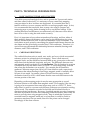
Azimuths
An azimuth is any direction read on a 360° circle, which relates to the cardinal
directions. North is read as both 0° and 360°, east as 90°, south as 180°, and west
as 270°. When using a compass to map a site, points are plotted according to the
azimuth between the site datum and the point, and the distance between them is
recorded generally in meters (m). The primary exception to this rule is when
documenting historic sites, which should be recorded in feet (ft) because it was
the measurement interval used to construct most historic structures in the United
States.
Regardless, the site datum is the reference point for all locational data recorded
at a site and, therefore, it is where all mapping activities must begin. The total
station serves the same purpose as a compass in terms of keeping track of how
azimuth designations relate to actual directions. However, it differs in that it can
not determine true or magnetic north by itself; an external compass must be used
to determine north, and then the direction is set on the total station.
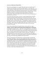
Figure 1-1: Azimuths. The figure shown above illustrates how azimuths are
referred to numerically, which increase in size in a clockwise direction. For
example, directly northeast has an azimuth of 45°, the azimuth for directly
southwest is 225°, and the azimuth for directly northwest is 315°. When moving
along an east-west axis, the azimuth designations are 90°/270°; on a north-south
line, the azimuths are referred to as 0°/180°.
1-2
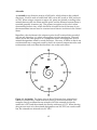
Bearings
A bearing is similar to an azimuth in that it refers to any direction on a circle.
However, how the directions are referred to differs from azimuths. Bearings are
used less frequently in archaeology to refer to locations, and definitely should
not be used when documenting general site locations. In fact, it is recommended
that bearings should not be used for archaeological site mapping since there is
potential for error in reading and determining bearing designations.
Nonetheless, bearings are useful to understand when using the total station for
site mapping, since they are used frequently for other mapping applications.
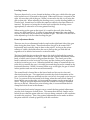
Figure 1-2: Bearings. As illustrated in the figure above, bearings are based on
four quadrants that are 90° angles divided in terms of northeast, southeast,
southwest, and northwest. To determine bearings in the two northern
quadrants, 0° represents north and 90° represents both due east and due west.
Likewise, when figuring out bearings in the two southern quadrants, 0°
represents south and 90° represents both east and west. For example, when
standing on a line that is oriented 15° east of north, its bearing is designated as N
15° E; when standing on a line that is 15° west of north, its bearing is N 15° W. In
addition, an azimuth of 45° is equal to a bearing of N 45° E; 210° is equal to S 30°
W; and 350° is equal to N 10° W.
Azimuths and bearings are useful when referring to the location of points
relative to one another at a site. For example, the extent of a lithic scatter at one
point may be located 50 m away from datum at an azimuth of 170°, or a bearing
1-3
of S 10° E. Or, a shell midden is eroding off a cliff edge, which at one point is
located 35 m from datum at an azimuth of 235°, or a bearing of S 55° W. The
points can be plotted on site maps using this information. However, when
generating a site map and plotting the site on larger maps or with larger scales, it
is necessary to know the site location in terms of its actual position on earth,
rather than just relative to another point.
1.2
UTM COORDINATES
When site mapping, archaeologists generally employ a combination of
azimuths/bearings and UTM (Universal Transverse Mercator) coordinates. In
some contexts, it may be useful to also determine locations relative to longitude
and latitude and/or United States Public Lands Survey (USPLS) coordinates.
Among various reasons, what map systems are used depends on the nature of
the mapping project, the location on earth, and what cartographic conventions
are used in that region. For official site maps in California, for example, it is
necessary to include the UTM coordinates, township and range information
(USPLS), verbal descriptions of the site locations, and site location maps, which
are plotted typically on USGS 7.5" Series maps or something comparable.
UTM coordinates may be conceptualized as a metric grid superimposed on the
earth in which the X-axis is oriented east-west and the Y-axis is north-south.
Coordinates on the X-axis are referred to as Eastings (E), and on the Y-axis as
Northings (N). Imagine the earth as a cylinder rolled out to form a flat grid. The
grid is composed of 60 zones that each consists of 6° of longitude (east-west
distance). When referring to longitude, the Prime Meridian that transects
Greenwich, England is set at 0°, which means that 180° is located in the center of
the Pacific Ocean. Therefore, Zone 1 refers to the 6° zone located in the ocean
immediately to the east of 180°. Zone 11 transects California and part of the
United States Southwest; Zone 19 includes part of Chile; and Zone 31 is located
immediately east of the Prime Meridian.
Easting coordinates are determined based on the north-south central line of the
zone being occupied. The false 0° Easting is set at an arbitrary point of 500,000 m
west of the centerline, which means that the centerline of each zone has an
Easting coordinate of 500000 E. The further one moves to the east, the larger the
Easting coordinate will be until the next zone is reached.
In contrast, in terms of the Y-axis, 0° refers to the equator, which is conceived of
as the dividing point between the northern and southern hemispheres. The
equator is 0° N for locations in the Northern Hemisphere. For UTM coordinates
in the Southern Hemisphere, 0° N is set at an arbitrary line located 10,000,000 m
south of the equator. The Northing coordinate increases in number as one moves
north beyond 0° N.
To reflect the north-south axis of the earth, zones (based on longitudinal degrees)
are divided into quadrilaterals, which are each composed of 8° of latitude. Each
quadrilateral is referred to by designated letters (i.e., C through X with the
1-4
exception of I and O). However, it is important to note that these letters are
dropped when referring to UTM coordinates within the United States. The UTM
grid on USGS 7.5" Series maps represents a simplified version of the worldwide
UTM grid.
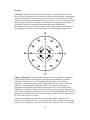
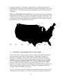
Figure 1-3: UTM Grid in the United States. The figure shown below represents
the worldwide UTM grid, as it appears superimposed on the United States. The
numbers at the top of the map refer to the degrees in longitude of the zones, and
the numbers at the bottom represent the zone numbers. The rectangles depicted
are quadrilaterals (6° longitude by 8° latitude).
120°
114°
11
12
108°
102°
96°
90°
84°
40°
32°
10
10
1.3
11
12
13
14
13
14
15
15
16
16
17
17
READING UTM COORDINATES ON USGS MAPS
In the United States, maps are made based on smaller units than quadrilaterals
that are referred to generically as quadrangles. Some maps encompass 2°
longitude x 1° latitude, for which the scale is 1:250,000. Since each degree is
composed of 60 minutes ("), the next smaller map is 1° longitude x 30" latitude,
which has a scale of 1:100,000. There are also 30" x 30" maps, scale of 1:125,000;
15" x 15" maps, scale of 1:62,500; and 7.5" x 7.5" maps with a scale of 1:24,000.
Logically, USGS 7.5" Series maps refer to squares that are 7.5" by 7.5". The 7.5"
maps are used most commonly when plotting the location of archaeological sites,
since they are small enough to show most changes in topography, but large
enough to depict the nature of the region.
On USGS 7.5" Series maps, the UTM grid is subdivided further into 1000 x 1000
meter units for easy reference. On some recent maps, the grid has been drawn
1-5
on the map itself; whereas, on other maps, blue ticks and numbers listed on each
side of the maps represent the UTM grid. Depending on who owns the map, it is
recommended that the blue ticks should be connected to draw the UTM grid on
the map to make it easier to read. The numbers on the left and right sides of the
maps, such as 3814, 3815, and 3816, are the Northing coordinates, which refer to
3814000, 3815000, and 3816000 m north, respectively. The numbers on the top
and bottom of the maps, such as 245, 246, and 247, are the Easting coordinates,
which are 245000, 246000, and 247000 m east, respectively. The last three digits
of the coordinates are omitted on the sides of the maps because they represent
locations within each of the 1000 x 1000 m grid units.
If the exact site location is known, then the UTM coordinates for the site can be
determined by using a UTM template on the appropriate USGS map. The
intersection of the X- and Y-axes on the template should be lined up on the center
of the site. If the site is relatively large (e.g., site dimensions of 200 x 300 m), then
it may be useful to generate two or more sets of UTM coordinates to represent
the full extent of the site. Regardless, the X-axis line on the template should
intersect the nearest UTM line south of the site, and the Y-axis line should
intersect the nearest UTM line west of the site.
When determining the UTM coordinates for a site, it is useful to always
remember the phrase "read right, then up", which means that the Easting
coordinate should be determined first and then the Northing coordinate. The
Easting coordinate is composed of 1) the numbers listed for the southern UTM
line as the first three digits (e.g., 246), and 2) the difference in meters between the
location of the site and the southern UTM line as the last three digits (e.g., 550
m). The Northing coordinate is based on 1) the numbers listed for the western
UTM line as the first four digits (e.g., 3815), and 2) the difference in meters
between the location of the site and the western UTM line as the last three digits
(e.g., 200 m). For example, a site is located in Zone 11 at 550 m east of the 246
Easting line and 200 m north of the 3815 Northing line. The UTM coordinates for
the site should be listed as 246550 E/3815200 N in Zone 11.
When site mapping, it is useful to visualize the UTM grid in one's mind based on
the UTM coordinates for datum, where north is located, and the distance
between datum and recorded points. For example, the UTM coordinates for the
site datum are 246550 E/3815200 N. The north line has been set up with a pin
flag marking a point that is 20 m directly north of datum. Therefore, the UTM
coordinates for the pin flag marking north are 246550 E/3815220 N. For another
example, a secondary mapping station has been set up 50 m directly west of
datum at the same site. The UTM coordinates for the new mapping station
should be 246500 E/3815200 N. The relative locations of points should be
engrained in one's mind to the degree that errors can be detected when looking
at the recorded UTM coordinates. One should always be asking the question "Do
these numbers make sense based on everything I know about the site?"
1-6
2.
BASIC COMPONENTS OF THE TOTAL STATION
2.1
PRISM REFLECTOR (ROD)
Basic Components
There are two basic components of the prism reflector. The prism reflector is an
updated version of the stadia rod that is used in conjunction with conventional
optical transits. The prism reflector itself is the small square-shaped piece that
contains a circular mirror. This piece is attached to the metal rod by screwing its
base into the top of the rod. Make sure that the prism reflector is screwed in
tightly, so that it will not fall off during mapping, but not so tight as to keep it
from being removed later. Both parts together will be referred to generically in
this manual as the rod.
How the Prism Reflector Operates
Unlike conventional transits, the advantage of the Topcon total station and
similar equipment is that the person recording the points does not have to read
numbers on the stadia rod to calculate locational information. Instead of relying
on the person’s eye, the total station emits a laser signal that bounces off the
prism reflector at the top of the rod and then returns to the gun. The distance
and slope at which the laser beam travels provides the basis on which the data
collector calculates the azimuth to and elevation of the point on which the rod is
placed.
Adjusting the Rod Height
The rod height may need to be adjusted regularly depending on the site
topography and where points need to be recorded. For example, the point to be
recorded may be located on a slope extending downward from where datum is
located. To compensate for the slope, it may be necessary to raise the rod higher
until the person operating the total station can see it.
There are two black spring-loaded grips on the rod used to adjust the height.
The rod can be extended or shortened when the grips are depressed by wrapping
the palm of the hand around them. The rod measures 1.65 m in height at its
shortest, and can be extended to a maximum of 3.78 m using both of the grips.
To raise the rod height, depress the top grip and pull the rod up to the desired
height. The height is marked in feet and meters on the metal surfaces
immediately above each grip. The rod is marked in 5 cm increments with
numbers and at each cm increment with single lines. The numbers above the top
grip extend from 1.65 m to 2.75 m.
If the rod height needs to be higher than 2.75 m, first make sure that the rod part
controlled by the top grip is fully extended to read 2.75 m. Then, depress the
bottom grip and extend the rod to the appropriate height. When the rod is fully
2-1
extended at both grips, the rod height will read 3.78 m. If the rod still can not be
seen from the total station, then a new mapping station needs to be set up.
Holding the Rod When Site Mapping
The most important aspect of holding the rod when recording points is to
maintain as much accuracy as possible. First, the base of the rod needs to be
placed precisely at the location that is to be recorded. If the rod can not be placed
directly on the point, then position it as close as possible and record the
difference in the field notes. For example, when recording a site that is partly
eroding off an unstable cliff edge, the rod should be placed some distance back
from the cliff where it is safe. Estimate how far the cliff edge is from where the
rod is positioned, and then write down the distance and direction. For example,
"the cliff edge is located 1 m directly south of point 50." The location of the point
can be corrected later when editing the job file for the site.
Second, it is important that the rod is level to ensure that the elevation is
recorded correctly. The rod has a built-in leveling bubble for this purpose. The
person holding the rod should stand in a stable position (it is best to have your
legs spread apart somewhat), and then firmly hold the rod near where the
leveling bubble is located. Once the person is in position and the rod is leveled,
the point is ready to be recorded. While the point is being shot, the person
should keep his/her eyes on the leveling bubble to make sure that the rod
doesn’t move.
The taller the rod is, the more difficult it is to keep it level in windy and
inhospitable conditions. Consequently, points should be recorded at the lowest
rod height possible to make it easier on the person holding the rod. The rod
height can be changed at any time and as many times as necessary. However, it
is critical that the person using the total station is notified each time the rod
height is changed so that it can be adjusted on the data collector.
If the rod holder forgets to tell the person using the total station that the rod
height has been changed, then the error can be written down in the field notes
and corrected later. The person needs to write down as much as he or she knows
about the following: the numbers of the points impacted, the rod height listed on
the data collector when the points were recorded, and the actual rod height. For
example, it can be written down that the rod height should have been 2.75 m
rather than 2.15 m for points 20 through 30.
Another rule of thumb is to never stand the rod up by itself. Rather, it should
always be held firmly by someone. The rod is unstable because of the point at its
base and, therefore, will eventually fall if not held. While the rod will be okay,
the prism reflector can be damaged. If the rod is going to be set down between
shooting points, then it is good to always place the cap on the mirror to prevent it
from being covered in dirt or damaged in some way.
2-2
2.2
TOTAL STATION (GUN)
The Topcon total station is referred to generically as the gun, which is an analogy
that will be used throughout this manual. The process of sighting the rod with
the gun, and then recording the locational data using the data collector, is
referred to as "shooting" points. The primary components of the total station are
the gun and tripod to which the data collector is attached.
The features on the gun that are relevant to its set-up and use are referred to in
two manners. First, the name for the feature as it is discussed in the Topcon
GTS-210 Series Instructional Manual is listed in Italics. By maintaining the
nomenclature, it will be easy for the user to consult the manual provided with
the equipment, if necessary. Second, many of the features are also referred to in
more simple terms that are handy to use in the field. For example, the sighting
collimator and telescope eyepiece are discussed simply as the sight and eyepiece.
Tripod
Several types of tripods that can be used to support the gun, most of which being
simple in their design and use. The primary differences between tripods include
material, maximum height, and weight. Materials include wood, aluminum, and
wood/fiberglass, of which aluminum tripods are the lightest (13-14 lbs.) and
wood/fiberglass ones (16-18 lbs.) are the heaviest and most durable. The kind of
tripod used depends on the circumstances of the mapping, including whether
the tripod has to be carried for long distances, if conditions are windy, and other
factors. The tripod described below is made of wood/fiberglass.
Black clamps located about midway down each of the legs control the length of
the legs. When a clamp is lifted up, the leg to which it is attached can be
extended or retracted. The clamp can be locked, thereby securing the leg length,
by pushing it downward against the leg. Whenever the gun is going to be placed
on the tripod, make sure that all of the clamps are locked down.
Another important feature on the tripod is the tripod screw that allows the gun to
be attached securely to the tripod. The tripod screw is a large black screw
attached to a metal arm located in the hole in the top of the tripod. When the
gun is to be attached to the tripod, the tripod screw should be screwed firmly
into the base of the gun.
For complex mapping projects, such as ones with multiple mapping stations,
more than one tripod is recommended. Having several tripods to work with will
allow for more efficiency when occupying multiple mapping stations and using
multiple back sight points. The tripods, along with tripod bracket (for leveling
purposes), can be set up such that the location of the gun and prism are easily
interchangeable.
2-3
Optical and Mechanical Plumb Bobs
There are two plumb bobs, so to speak, that can be used to accurately position
the gun on the site datum or any other locational marker. In all cases, the
location from which points are going to be shot will have to be established before
setting up the gun. Depending on various factors that are discussed in detail in
section 3, the location can be marked with benchmarks, nails, pin flags, or stakes.
Regardless of what the location is marked with, the gun will have to be
positioned precisely over the marker to maintain precision in distance
measurements. Either plumb bob can be used to position the gun depending on
the preference of the user.
First, there is the optical plummet telescope, or optical plumb bob that looks like
another knob and is located immediately to the left of the data screen. The
optical plumb bob can be viewed through to see the ground directly below the
center of the gun. When using this plumb bob, the gun can not be screwed into
the tripod, since it will obscure the view. The gun must be sitting on top of the
tripod loosely, so that it can be shifted around until it is positioned directly over
the marker. When looking through the knob, there are two black circles and one
dot arranged in a "bulls-eye" fashion that allow the user to line up the gun
precisely on a location.
Second, there is the mechanical plumb bob that can be used for the same
purpose. The four components of the mechanical plumb bob are stored along
with the gun. One, there is a small metal bar that is shaped like a V with a hook
extending from the base of the V, which allows for the plumb bob to be attached
to the tripod. The ends of the top of the V are inserted into the base of the tripod
screw. Two, there is the string that extends between the metal bar and the plumb
bob. The string is attached to the hook at the base of the V. Three, there is a
metal strip that has two holes in it and is curved on both ends. The string is
threaded through the metal strip such that it can be used to adjust the length of
the string. Four, there is the actual plumb bob that is attached to the other end of
the string, and should hang immediately above the marker.
There are advantages and disadvantages to using both kinds of plumb blobs.
The primary advantage of using the optical plumb bob is that it can be used in
windy conditions, whereas the mechanical plumb bob will have the tendency to
sway too much. However, the optical plumb bob affords a limited view of the
ground below the gun. It is easy to get "lost", meaning that it hard to tell exactly
where the marker is located relative to the "bulls-eye" when looking through the
knob. (Note: If you lose the mark on the ground that you are trying to set up
over, it can be helpful to use your foot to relocate yourself and move inwards
toward the target point.) The mechanical plumb bob is best to use when the
weather is calm, and it is easy to see the location of the plumb bob hanging in the
air relative to the marker immediately below it.
2-4
Leveling Screws
There are three leveling screws located at the base of the gun, which allow the gun
to be leveled once it is secured to the tripod. When one of screws is turned to the
right, it lowers that side of the gun. When it is moved to the left, it will raise the
gun on that side. When adjusting the leveling screws, use the leveling bubble, or
circular level, located next to where the connector cable for the data collector is
inserted. The process of using the circular level to adjust the leveling screws
appropriately is referred to as coarse-grained leveling.
When setting up the gun on the tripod, it is useful to have all of the leveling
screws set at the same level. It is best to have them all rotated the same number
of turns so that they are positioned at a middle height. This allows for the screws
to be adjusted up or down when leveling the gun.
Focus Adjustment Knobs
There are two focus adjustment knobs located on the right-hand side of the gun
when facing the data screen. These knobs allow the gun to be rotated 360°
horizontally and vertically from its base on the tripod. As long as the prism
reflector is visible, the knobs allow the user to line up the gun with the rod
regardless of its relative horizontal or vertical location.
The lower knob that juts out from the gun to the right is the knob that controls
the horizontal orientation of the gun. There are two separate adjustments on the
knob, of which one is closer to the gun than the other. The closer part of the
knob is referred to as the horizontal lock clamp, and the further part is referred to
as the horizontal tangent screw. When horizontal lock clamp is turned all the way
to the left, or towards the gun, it is totally loose and the gun can be rotated in any
horizontal direction. When it is turned all the way to the right, the gun is locked
in that position and can not be moved horizontally.
The second knob is located above the lower knob and juts out in a forward
direction from the gun. The upper knob controls the vertical orientation of the
gun, of which the parts are referred to as the vertical lock clamp and vertical tangent
screw. In contrast to the horizontal lock clamp, when the vertical lock clamp is
turned all the way to the right, it is loose and the eyepiece can be rotated up or
down. The gun is locked in position when the vertical lock clamp is turned all
the way to the left. Whenever a point is being shot, it is essential that the lock
clamps be locked down in this manner.
The horizontal and vertical tangent screws control the fine-grained adjustment
once the lock clamps are locked down. This means that the lock clamps can be
locked down when the prism reflector is close to being centered on the crosshairs
viewed in the eyepiece. Then, fine-grained adjustments can be made such that
the prism reflector is lined up perfectly with the crosshairs.
2-5
Sight and Eyepiece
The easiest way to line up the crosshairs on the prism reflector is to rely on the
sighting collimator, or sight, which is located on the top of the gun below the
carrying handle. The sight can be used to get the gun into range with great
accuracy without having to look through the eyepiece. The key is to line up the
triangle viewed in the sight on the prism reflector. This should place the prism
reflector close enough to the crosshairs such that the focus adjustment knobs can
be locked down without having to look through the eyepiece. Once the knobs
are locked down, the user can look through the eyepiece and make fine-grained
adjustments to line up the prism reflector on the crosshairs perfectly. However,
it will take some practice using the sight and knowing how the sight works in
order to do this accurately every time.
There are two ways to focus the eyepiece such that both the prism reflector and
the crosshairs can be viewed clearly. First, if the prism reflector is blurry, rotate
the gray ring, or objective focusing knob, that encircles the eyepiece until it is clear.
Second, if the crosshairs are blurry, adjust the small black knob that is part of the
eyepiece, which is known as the reticle focus knob.
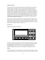
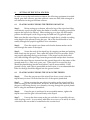
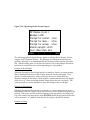
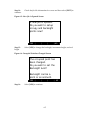
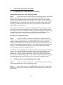
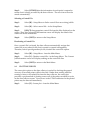
Data Screen
Figure 2-1: Data Screen on the Gun.
MENU
ESC
POWER
F1
F2
F3
F4
ANG
The gun can be used without the data collector, and that is when the data screen
on the gun is used for more purposes. For more information on how to use the
gun independent of the data collector, refer to the Topcon GTS-210 Series
Instruction Manual. However, it is more common that all operations are
conducted using the data collector, to which the gun is regarded as a “slave.”
Battery
The BT-23Q battery is attached to the gun on the right hand side when facing the
eyepiece and data screen. The battery locks into place with a locking lever at the
2-6
top of the battery. It is essential that the battery be re-charged daily when
conducting fieldwork. There should always be at least one fully charged spare
battery in case the one being used needs to be replaced.
The battery must be re-charged with the charger that is supplied with the Topcon
equipment. To do this, simply connect the cable that extends from the charger to
the plug-in at the top of the backside of the battery. Then, plug the charger into
an outlet. It should take about 1.5 hours for the battery to recharge. The charger
will display a green light when the recharging process is finished.
To know when the battery needs to be recharged, the battery level is indicated on
the data screen with small black bars positioned in the lower right hand corner.
When three bars are shown, the battery is fully operational. Two bars means that
the battery level is going down, but it is still possible to take distance
measurements. When there is one bar blinking, it means that the battery should
be replaced immediately. The length of operating time for the battery varies
depending on factors such as the ambient temperature, how long the battery was
charged for, and how many times it has been charged and drained. Note: the
amount of charge stored in the battery each time it is charged diminishes
gradually and will eventually need to be repacked (in 2-3 years depending on
usage).
2.3
DATA COLLECTOR
Basic Components
Environmental Box
The data collector is stored in an environmental box to prevent the elements from
penetrating into the equipment. In particular, the environmental box prevents
heavy misting and light rain from affecting the performance of the data collector.
However, one note of caution is that condensation can build up inside the
environmental box in humid and sunny conditions. In humid environments, it is
recommended that the data collector should be taken out of the environmental
box when not in use and allowed to "breathe." Furthermore, it may be necessary
to clean the contacts on the data collector regularly, even nightly, to prevent
potential problems. Too much humidity (more than 90% relative humidity) can
corrode the contacts such that data collector can not read information from the
gun, and therefore can not record points. In general, the data collector should be
stored in moderately cool, shady, and dry conditions as much as possible when it
is not being used.
HP-48GX Calculator and TDS-48GX Survey Card
The data collector is composed of the HP-48GX calculator with TDS-48GX survey
card that is inserted into the back of the calculator. The data collector refers to
the calculator when the survey program is enabled. If some of the calculator
features need to be used, exit out of the survey program by selecting [EXIT] in
the Main Menu and then [YES] when the screen displays “Are you sure?” Then,
2-7
remove the overlay that is on the keyboard, which lists all of the key options for
the data collector, to view the calculator key options. For further discussion of
the calculator features, refer to the HP 48G Series User's Guide.
Batteries
There are two parts of the data collector that use batteries: the calculator and the
RAM card. It is essential that there are always spare batteries in the field.
Whenever one is preparing to go into the field to conduct site mapping, make
sure that extra batteries of both kinds are included in the bag in which the data
collector is stored.
The calculator is operated using three AAA alkaline batteries. To change the
batteries, open the environmental box by unscrewing the two spring-loaded
screws located on the front of the box when viewing the calculator. Then, lift the
calculator out carefully and turn it over. The batteries are located inside the
calculator at the base of its backside.
The RAM card is located immediately below the survey card in the back of the
calculator. The card uses one 3-volt lithium battery (CR2016) that should be
replaced about once a year. When the battery is low, it will be indicated by a
symbol displayed on the data collector screen: ((=)).
To change this battery without risking losing data on the RAM card, follow the
instructions provided in the HP 48G Series User’s Guide (Appendix A) and as
paraphrased below:
1.
Back up your data prior to replacing the battery.
2.
Remove the data collector from the environmental box, turn it over,
and remove the plastic port cover to access the RAM card.
3.
With the calculator turned ON, hold the RAM card in place with
one hand as you remove the battery from the RAM card in your other
hand. Direct quote from the HP 48G Series User’s Guide: The RAM card
runs off the calculator batteries only when the calculator is ON. RAM
memory may be lost if you remove a RAM card battery while the
calculator is off, or while the card is not installed in the calculator.
4.
Replace the port cover and put the calculator back into the
environmental box.
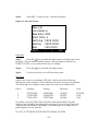
Data Screen
The data collector is turned on by pressing the [ON] button that is located in the
lower-most left-hand corner of the keyboard. It is turned off by pressing the [æ]
right-hand arrow key (located immediately above the ON button) and the [ON]
button at the same time.
2-8
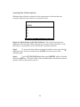
Accessing Data Collector Options
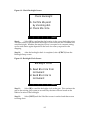
When the data collector is turned on, the screen shown is the one that was
occupied when the data collector was turned off last.
{HOME}
4:
3:
2:
1:
|VECTR| MATR | LIST| HYP| REAL| BASE|
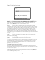
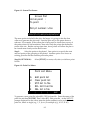
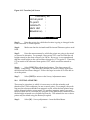
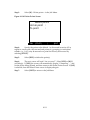
Figure 2-2: Home Screen on the Data Collector. The screen shown above is
displayed when the data collector program is not open on the calculator. From
this screen, it is possible to access and use the calculator functions.
Step 1:
To access the data collector program from this screen, press the [ ]
alpha key twice, which is located above the [ON] and arrow keys on the
calculator pad.
Step 2:
Type in [T] [D] [S] [4] [8] and then press [ENTER], which is located
above the [ON] key. The next screen will be the Main Menu for the data collector
options, which is discussed in section.
2-9
3.
ESTABLISHING THE SITE DATUM
In some contexts, the site datum will have already been established and can be
occupied readily if there is some permanent marker indicating its location. If
there are benchmarks or other known points located on or near the site, then one
of these points should be occupied first because they are the most accurate. Even
if a benchmark is located several hundred meters or more from the site, but is
still sighted with the gun, then it can be used to set up the location of the datum.
In many situations, it will be necessary to establish the site datum as a new point,
particularly when recording the site for the first time, or in an area where no
permanent markers can be left because of potential looting and/or disturbance.
3.1
SELECTING THE SITE DATUM
Before selecting the site datum, the site boundaries should be determined and
ground characteristics assessed. The extent and location of natural features such
as bedrock exposures, gullies, cliff edges, and dense vegetation that obscures
ground visibility should be noted, and flagged if needed. Furthermore, all
significant cultural features, such as structures, different site loci, areas of
midden erosion, and dense concentrations of artifacts (e.g., flint knapping
stations) should be noted and flagged. Once the site characteristics have been
assessed and the ones that are going to be mapped are marked in some clear
fashion, then the location of the site datum can be determined.
Unlike conventional mapping, where the datum should be placed centrally in the
site, the datum or primary mapping station should be established where the line
of sight is the best. One mapping station may be sufficient for small and simple
sites. However, complex sites (i.e., large size, irregular topography, etc.) may
require several mapping stations to complete the job. Therefore, the site datum
should be placed in a location from which all of the mapping stations are visible.
Furthermore, it is recommended that the mapping stations should be situated
outside of the site boundaries to ensure that no points recorded are too close to
the gun. Contrary to one’s intuition, measurements taken at greater distances are
more accurate than those taken at close range.
If there are no constraints on leaving permanent markers, then there are several
options for establishing the site datum depending on how often the area is going
to be mapped. In cases where the site is going to be returned to again and again,
it is recommended that site datum are made of durable materials, such as sinking
rebar reinforced with concrete into the ground. However, more simple options
include pounding in a metal or wooden stake and clearly labeling it with the site
number.
If the datum marker must be removed after the mapping has been completed,
then use a large nail (i.e., PK nails). Then, mark the stake or nail with flagging
tape and pin flags to ensure that it can be relocated easily. It is important to
maintain as much accuracy as possible; it should be possible to relocate the
points for mapping stations down to the centimeter.
3-1
3.2
ESTABLISHING NORTH
Step 1:
After datum has been marked, the next step is to establish the north
direction from datum. Set up a reliable and accurate compass directly over the
datum marker. It should be sitting in a stable and level position on a tripod.
Step 2:
Line up the compass to north.
Step 3:
Using a measuring tape, pace 20 m on the north line. When the
walker reaches 20 m, the person who is sighting the north point should make
sure that the walker is lined up directly on the north line. When the walker is in
the right position, he or she should place one or more pin flags in the ground to
mark the point.
Step 4:
Remove the compass from datum.
Step 5:
Set up the total station on the same exact location.
3-2
4.
SETTING UP THE TOTAL STATION
In order to set up the total station on datum, the following equipment is needed:
tripod, gun, data collector, gun-data collector connector cable, and recharged or
new batteries for the gun and data collector.
4.1
PLACING AND LEVELING THE TRIPOD ON DATUM
Step 1:
Before setting up on datum, adjust the legs of the tripod until they
are relatively equal in length, unless the datum is located on sloping ground that
requires the tripod to be skewed. When setting up on a slope, the most stable
position for the tripod is with 2 legs set up downhill and 1 leg placed uphill.
Make sure that the tripod legs are extended to a length that is suitable according
to the height of the person(s) using the gun. He or she should be able to look
readily through the eyepiece regardless of its orientation.
Step 2:
Place the tripod over datum such that the datum marker can be
seen through the center of the tripod.
Step 3:
Secure the ends of the tripod legs by stepping on them and pushing
them firmly into the ground. Then, make the tripod as level as possible, which
may require adjusting the legs several times. If the tripod can not be leveled
well, then dislodge the tripod legs from the ground and readjust their locations.
How far the tripod legs are inserted into the ground depends on the nature of the
ground surface (i.e., sand, rock, grass, etc.). If the tripod is on sand, the legs
should be planted deep into the sand (about 5 cm) for more stability. If the
ground is rocky, and if this is permissible at the location, it is recommended that
holes for the legs should be chipped into the ground surface.
4.2
PLACING AND LEVELING THE GUN ON THE TRIPOD
Step 4:
Place the gun on top of the tripod, but do not screw it into the
tripod head yet since it will obscure the view of the optical plumb bob.
Step 5:
Before securing the gun, adjust its position on the tripod until it is
level according to the circular level. However, at the same time, make sure that
the gun is still sitting directly over datum by viewing through the optical plumb
bob or using the mechanical plumb bob.
Step 6:
Once the gun is positioned in an acceptable manner, tighten the
tripod screw until the gun is secured firmly to the tripod.
Step 7:
Line up the data screen on the gun such that it is parallel with two
of the leveling screws. In your mind, label these two screws as A and B, of which
A should be the screw that is located below the circular level.
4-1
Step 8:
Rotate screw A until the leveling bubble moves away from the
edges of the circular level and from the ends of the plate level. The plate level is
located immediately above the data screen.
Step 9:
Rotate the gun until the data screen is parallel to screws A and C.
Rotate screw C until the leveling bubbles are centered better.
Step 10:
Rotate the gun such that the data screen is parallel to screws B and
C. Check the plate level to see if the gun has been leveled enough. If the gun still
needs to be leveled, then rotate screw B, which will require further adjustments
for screw A.
Step 11:
Continue to rotate the gun and adjust the screws until the gun is
leveled according to both the circular and plate levels.
Leveling the gun is an art that requires some practice. Make sure that each screw
is not being rotated repetitively to the left and to the right when shifting from
one gun orientation to another. It is easy to get stuck continually adjusting the
screws up and down by the same amounts and not getting anywhere in terms of
leveling the gun. To avoid this problem, choose one of the screws as a pivot
point, and adjust the other two accordingly.
4.3
LINKING THE DATA COLLECTOR TO THE GUN
Step 12:
Once the gun is leveled, attach the data collector to one of the
tripod legs.
Where the data collector is placed depends on the direction in which most of the
points will be shot. For example, if most of the points to be shot are located to
the east, then the data collector should be set up either on the northwest or
southwest side of the total station. The data collector should be readily
accessible when shooting points, but it should also be skewed to the side so it
will not get in the way of the person looking through the eyepiece.
Step 13:
Secure the data collector by undoing one side of the black rubber
band that is attached to the back of the data collector. Wrap the band around the
tripod leg and then re-attach the end to the data collector.
Step 14:
Connect the cable between the gun and data collector. Do not
attempt to force the cable into the gun. The cable end will fit only when oriented
in one direction, so move it around until the correct orientation is found and then
insert it firmly. Make sure that the cable end attached to the data collector is in
place and locked.
4.4
TURNING ON THE GUN
Step 15:
Once the total station has been set up on the site datum, turn on the
gun and data collector.
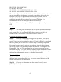
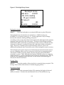
4-2
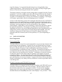
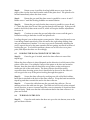
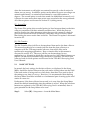
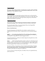
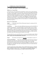
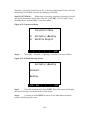
Figure 4-1: Setup Screen on the Gun.
V 0SET TURN
MENU
PSM:-30mm PPM: 0
↓
↑
___ ENTER
ESC
POWER
F1
F2
F3
F4
ANG
Step 16:
Make sure that the horizontal and vertical lock clamps are loose, so
that the gun can be moved. Rotate the part of the gun with the eyepiece until it is
upside-down, and then return it to its original position. The screen should now
display readings for vertical (V) and horizontal (HR) angles, which will need to
be reset. The following is an example of what will appear in this screen.
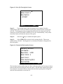
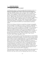
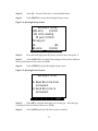
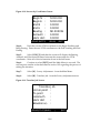
Figure 4-2: Main Screen on the Gun.
V :
HR :
0SET
90°10'20"
120°30'40"
HOLD
MENU
HSET
P1↓
F3
F4
ESC
POWER
F1
F2
ANG
0SET Option
The 0SET conventionally refers to north. This option allows the user to reset the
direction in which the gun "thinks" that it is pointed to 0°00'00". This option (or
HSET) must be set to reflect either magnetic or true north each time the total
station is set up on a mapping station. The data collector will calculate the UTM
coordinates for recorded points based on the north direction set on the gun.
HOLD Option
4-3
The HOLD option freezes the angle shown on the data screen such that the gun
can be rotated and the angle will not change. This option does not have much
applicability in site mapping.
HSET Option
The HSET option is similar to the 0SET, although it can be set to any angle. This
is useful when setting up on a secondary mapping station. Rather than
establishing a north line when setting up on another location, the gun sighted to
datum. The backsight azimuth from datum to the point now occupied can be
calculated when the point was shot, and then it can be used as the horizontal
angle for the HSET.
P1↓ Option
The P1↓ Option scrolls the screen to the next page.
4-4
5.
DATA COLLECTOR OPTIONS AND SETTINGS
5.1
MAIN MENU
Some Main Menu options have been omitted from this manual since they are not
relevant to archaeological site mapping. These options are useful for those who
need to translate distances and angles from paper to the ground, as when
constructing buildings or delimiting property boundaries. For further
information regarding Stake Out, Leveling, Sun Shot, Curve Menu, and Print
Menu, refer to the TDS-48GX Surveying Card User’s Manual and TDS-48GX
Surveying Card Reference.
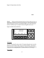
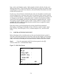
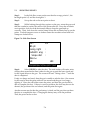
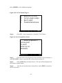
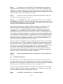
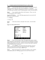
Figure 5-1a: Main Menu on the Data Collector (Page 1)
G
H
I
J
K
L
| MORE|
< Select G to S >
Open/Edit a job
Setup menu
Stake out
Traverse/Side shot
Show directory
Leveling
|
|
|
|EXIT|
Main Menu Options
[G] - Open/Edit a Job
The Open/Edit a Job Menu includes most of the options that are used to create,
open, modify, and delete jobs and individual points. The Job refers to the
individual site file, or any discrete set of points. For example, some files may
contain locations for benchmarks and other points that will be used repeatedly to
map several sites in the area, which are referred to as control files.
The Job Menu options are discussed in detail in sections 6 (creating and opening
jobs) and 12.3 (modifying and deleting jobs and points.)
[H] - Setup Menu
The Setup Menu includes all of the basic setup options for the data collector,
such as distance unit (i.e., meter), baud rate, parity, enabling prompts for various
data, and what kinds of coordinates will be displayed (i.e., Northing, Easting,
and elevation.) The most relevant Setup Menu options are discussed in section
5.2. In addition, the Setup Menu includes options for selecting and deselecting
5-1
control files. When and how to create, open, and use control files are discussed
in section 9.1.
[J] - Traverse/Side Shot
The Traverse/Side Shot option is used to shoot points. How to take side shots to
record points is discussed extensively in section 7.
[K] - Show Directory
The Show Directory option displays the names of all of the job files that are
stored currently in the data collector.
More Main Menu Options
The screen shown below is accessed from the first screen of the Main Menu by
selecting [MORE].
Figure 5-1b: Main Menu on the Data Collector (Page 2)
M
N
O
P
Q
R
S
|
CO-GO Menu
Survey Adjustment
Sun shot
Screen plot
Curve menu
Print menu
File Transfer
|
|
|
|EXIT
|
[M] - CO-GO Menu
The CO-GO Menu contains options that are used primarily to obtain information
for editing job files, such as calculating the azimuth and distance between two
points, which can be used to adjust point locations. In addition, there is an
option for determining the site area based on specified points, such as the
midden boundary, which can be useful when filling out site forms. The relevant
CO-GO Menu options are discussed in sections 9.3 (calculating the site area) and
12.3 (editing errors).
[N] - Survey Adjustment
The Survey Adjustment options are used primarily to edit points and/or entire
job files. Options include adjusting the elevation for one or more points, such as
5-2
when the instrument or rod height was entered incorrectly or the elevation for
datum was set wrong. In addition, points can be shifted in space according to an
azimuth and distance, or rotated around datum by a specified number of
degrees. The second option is used when north was established incorrectly or it
is known for some reason that some points were recorded at the wrong azimuth.
All of these options are discussed in section 12.3 (editing errors).
[P] - Screen Plot
The Screen Plot option plots recorded points (or lines between them) on the data
collector screen based on their azimuths and directions. While the plots are
small in display size, their advantage is that they provide a means to check for
gross errors in the data while in the field, where they can be corrected, rather
than finding the errors weeks later in the lab. The Screen Plot option is discussed
in section 9.2.
[S] - File Transfer
The File Transfer allows job files to be transferred from and to the data collector.
This manual explains how to transfer job files from the data collector to a
computer with the TFR-map transfer software, from which files can be
transferred to mapping applications. How to transfer files in this manner is
discussed in section 10.1. However, job files can be transferred to any
application (e.g., Kermit) in which they can be saved as ASCII files for future use.
Job files can also be downloaded using a modem or to another TDS-48GX data
collector, both of which options are discussed in the TDS-48GX Surveying Card
User’s Manual.
5.2
BASIC SETTINGS
In general, the basic settings for the data collector, as displayed in the Setup
Menu, should be checked whenever the total station is being taken into the field.
If the total station is being used on a daily basis, then there is no need to check
the settings every time it is set up. However, it is recommended that checking
the Setup Menu should be included as a fundamental part of setting up the total
station at a new site.
Furthermore, if the data collector freezes and/or is reset, then the Setup Menu
should be checked immediately after the problem is solved. When the calculator
batteries are replaced or the TDS-48GX Surveying Card is reinstalled, there is
great potential for the Setup Menu to be reset.
Step 1:
Select [H] – Setup menu – from the Main Menu.
5-3
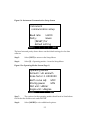
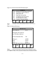
Figure 5-2: Setup Menu
Setup Menu
G
Time / Date
H
Devices
I
Operating modes
J
Repetition modes
K
Select contrl file
L
Deselect contrl file
|
|
|
|
|EXIT |
Setup Menu Options
The Setup Menu options that are relevant to archaeological site mapping are
primarily Devices, Operating Modes, Select Control File, and Deselect Control
File. When and how to use the Devices and Operating Modes options are
discussed below, while control files are discussed in section 9.1.
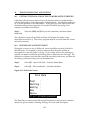
Step 2:
Select [H] – Devices – from the Setup Menu.
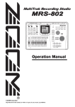
Figure 5-3: Device Setup Screen
Device Setup
Instrmnt : >Topcon
Model : >GTSB-D & 4
Instrument: >Enable
Instr dist unit:>Meter
Dist measur:>Single
Use lumi-light:>No
|
|COLLI|
|FAST|
|EXIT |
Step 3:
The options for the device setup should read as listed above.
Check that the instrument distance unit reads METER. However, when mapping
historic sites, select FEET as the distance unit by pressing the right arrow key.
Step 4:
Select [EXIT].
5-4
Figure 5-4: Instrument Communication Setup Screen
Instrument
communication setup
Baud rate:
>1200
Parity:
>Even
[RESET] for
default setting
|RESET|
|
|
|
|EXIT |
The baud rate and parity shown above are the default settings for the data
collector.
Step 5:
Select [EXIT] to return to the Setup Menu.
Step 6:
Select [I] – Operating modes – from the Setup Menu.
Figure 5-5a: Operating Modes Screen (Page 1)
Operating Modes
Azimuth: >N. azimuth
Scale factor: 1.0000000
Earth curve adj: >OFF
Storing pause:
>ON
Dist unit: >Meter
Angle unit: >Degree
| MORE| |
|
|
|EXIT|
Step 7:
The options for the operating modes should read as listed above.
Check that the distance unit reads METER.
Step 8:
Select [MORE] to view additional options.
5-5
Figure 5-5b: Operating Modes Screen (Page 2)
OP Modes (cont.)
Beeper:> ON
Prompt for rod Ht: >Yes
Prompt for desc.: >Yes
Prompt for setup: >Yes
Station length: >100
Coor. Disp:>N,E, ELV
| PREV|
|
|
|
|EXIT|
The following options should always appear as shown above: Beeper, Station
Length, and Coordinate Display. The prompts for different information are
optional, although is recommended that the Prompt for Description should be
ON. When learning how to use the data collector, all of the prompts should be
turned on to remind the users about inputting new information.
Prompt for Rod Height
When the Prompt for Rod Height option is turned on, there is a screen prompt
that is displayed before each shot is taken that asks for the rod height. This
option is useful particularly when working in an area in which there are
dramatic changes in elevation, which requires constant alterations in the height
of the rod (e.g., when recording midden slump down the side of a knoll). The
screen prompt is a useful reminder to note the change in the rod height.
Prompt for Description
When the Prompt for Description is on, there is a screen prompt that is shown
immediately after each shot is taken that allows for a new point description to be
entered. The screen will show the description of the previously recorded point.
If it is the same as the description, then [ENTER] should be pressed and the shot
will be recorded. If it differs, then the new description should be entered.
Prompt for Setup
5-6
When the Prompt for Setup is turned on, there is a screen prompt that is shown
when the Occupy Point is changed (e.g., moving from the site datum to a
secondary mapping station). The screen will display the Backsight Setup, which
is the screen in which the instrument height and rod height can be changed. The
Backsight Setup options are discussed in section 6.1.
Step 9:
Select [EXIT] to return to the Setup Menu.
Step 10:
Select [EXIT] to return to the Main Menu.
5-7
6.
CREATING A NEW OR OPENING AN EXISTING JOB FILE
Once the Setup Menu has been checked, the next step is to create a new job file or
open an existing one. Each site should be assigned its own job file. In general, it
is better to store discrete groups of points as separate files than to include them
in one file. For example, there are several known points within the survey area
(e.g., USGS benchmarks), which are used to generate UTM coordinates for all of
the sites recorded. The known points should be stored in a file separate from all
of the job files representing sites. If, at a later date it seems appropriate that two
or more groups of points should be included in the same file, then the groups can
be merged. Merging files, which is an option in the TFR-Map program, is
discussed in section 12.
6.1
CREATING A NEW JOB FILE
Step 1:
Select [G] – Open/Edit a job – from the Main Menu.
Figure 6-1a: Job Menu (Page 1)
Job
G
H
I
J
K
L
Menu
Create new job
Open existing job
Current job info
Edit coordinates
Raw data file
Delete job
| MORE| |
|
|EXIT
|
Figure 6-1b: Job Menu (Page 2)
M
N
|
Rename file
Delete points
|
|
|
6-1
|EXIT
|
Step 2:
Select [G] – Create new job - from the Job Menu.
Figure 6-2: New Job Screen
New Job
Job name(α):
Raw data: >ON
Start Point: 1
Northing : 5000.0000
Easting : 5000.0000
Elev
: 100.0000
| CREAT|
|
||
|EXIT
|
Job Name
Step 3:
Press the [ ] key to enable the alpha option, and then type in the
job name. The job name should be based on the site name or number (e.g.,
SCRI277, PUNTA, etc.) to make the file easy to identify.
Step 4:
Press the [ ] key to disable the alpha option.
Step 5:
Use the arrow keys to scroll down the screen.
Raw Data
Job files are stored as coordinate (.CR5) files, which contain the following
information: point number, UTM coordinates, elevation, and point description.
The following is an example of how points are stored in a coordinate file.
Point #
1
2
3
Northing
Easting
Elevation
Note
3776740.0000
3776760.5490
3776763.6723
233585.0000
233560.3238
233557.5869
130.0000
145.2897
143.3465
DATUM
CON
CON
In contrast, raw data (.RW5) files store the actions performed by the data
collector user, including shooting points, moving to a new Occupy Point, and
changing the instrument or rod height. The following is an example of how
points appear in a raw data file.
OC, OP1, N 3776740.000,E 233565.000, EL130.0000,--DATUM
6-2
BK, OP1, BP1, BS0.0000, BC0.0000
LS, HI1.5650, HR1.8000
SS, OP1, FP2, AR0.0000, ZE87.37100, SD9.060, --CON
SS, OP1, FP3, AR0.0000, ZE87.37510, SD9.050, --CON
The raw data file provides a detailed field record of all of the activities conducted
on the data collector, which can be very useful when editing job files. In this
example, it shows the UTM coordinates and elevation of datum, which is
designated as the Occupy Point, and is point # 1. It displays the instrument and
rod height inputted when any point is first occupied. Therefore, it is
recommended that the raw data option should be ON always.
Step 6:
ON.
If the raw data option is OFF, then use the right arrow key to select
Start Point
Step 7:
The start point, which will be the site datum, should be numbered 1
unless there is some advantage to starting with another number. In the case of
using control files, it is recommended that the start point for the job file is
numbered 100 or above, which is discussed in detail in section 9.1.
Locational Coordinates for Datum
Step 8:
Enter the Northing and Easting for the site datum. If the site has
already been recorded, then the UTM coordinates may be copied from the site
record. If not, they can be obtained by using a GPS unit in the field, or calculated
based on plotting the site on a USGS 7.5’ series map or something comparable.
For several reasons, it may be easier to use arbitrary points for the site datum,
such as the default UTM coordinates on the data collector - Northing 5000 and
Easting 5000. One, the UTM coordinates for the location may not be known at
the time of mapping. Two, using arbitrary numbers such as these makes it easier
to notice errors in locational data when out in the field. The coordinates may be
adjusted later in the mapping process, as described in section 10.5.
Elevation for Datum
Step 9:
Enter the elevation for the site datum. The elevation may be
obtained in the manners described above, or may be entered arbitrarily as 100,
which is the default on the data collector.
Step 10:
Once the site information has been entered correctly, select
[CREAT] in the New Job screen.
6-3
Figure 6-3: New Job Description Screen
Enter Point 1
description
: START
|CREAT||
|
|EXIT
|
Step 11:
Type in the name of the first point to be occupied, which is
represented by the UTM coordinates and elevation entered when creating the
new file. The first point to be occupied should be the site datum and may be
referred to as DATUM, MAP1, BENCH (if it is also a benchmark), or any other
term that clearly indicates the nature of the point.
Step 12:
Select the [ ] key to disable the alpha option.
Step 13:
Select [CREAT] to proceed with creating the file. The screen
momentarily will read – Storing point 1 (or whatever number is designated as
the start point).
Figure 6-4: Current Job Information Screen
Current Job Info.
Job Name :
Raw data : >ON
Start Point: 1
Last Point:
Free memory(pts):
Control file:
|
|
|
|
|EXIT |
The first three options (job name, raw data, and start point) are the same as those
listed in the previously shown New Job screen. The last three options (last point,
free memory, and control file) are more relevant when opening an existing file,
and are discussed below in section 6.2.
6-4
Step 14:
continue.
Check the job file information for errors and then select [EXIT] to
Figure 6-5: New Job is Opened Screen
A new job is opened.
Do you wish to setup
occupy and backsight
points now?
| YES
Step 15:
height.
|
|
|
| NO
|
Select [YES] to change the backsight, instrument height, and rod
Figure 6-6: Occupied Point has Changed Screen
The occupied point has
been changed.
Do you wish to set the
Backsight & HI?
Backsight can be a
point or an azimuth.
| YES
Step 16:
|
|
|
Select [YES] to continue.
6-5
| NO
|
Figure 6-7: Backsight Setup Screen
Backsight Setup
>BS azm:
0.0000
BS circle reading
Of gun: 0.0000
Occupy pt:
HI:
HR:
BS Azm:
0.0000
|SOLVE|CHEC|
|FAST|CIRCL|EXIT|
Backsight Azimuth
Step 17:
Enter the backsight as an azimuth (BS azm) or point (BS point).
The backsight may be entered as an azimuth (i.e., 0.0000), bearing (i.e.,
N0.0000E), or as a known point (e.g., 5). Use the right arrow key to change
between the azimuth, bearing (BS brg), and point.
According to the scenario described in this manual, the backsight for the primary
mapping station should be the north point. Therefore, the backsight azimuth
should read 0.0000 (at both the top and bottom of the screen) to indicate that the
orientation of datum is correlated with north, rather than another azimuth or
angle. However, if another point in the landscape is known, such as an
additional benchmark, then it should be used as the backsight for more accuracy.
The backsight point option may be used when the total station has been moved
to a new mapping station, and it is necessary to link the new mapping station
with datum. When occupying datum, the new mapping station should be
recorded as a point. Then, when the total station is placed on the new mapping
station, datum (e.g., point 1) should be used as the new backsight point. How to
establish a new mapping station and link it to the datum with a backsight is
discussed in detail in section 8.
Occupy Point
Step 18:
Enter the number of the point that is currently being occupied. The
Occupy Point will be either datum or another mapping station.
Instrument Height
Step 19:
Enter the instrument height (HI), meaning the height of the total
station, in meters. Calculate the measurement down to the millimeter (e.g.,
6-6
1.756). The instrument height is measured from the ground to a line indented on
the side of the gun that is parallel with the eyepiece.
The height may be measured with a conventional tape measure or a stadia rod
for better accuracy. Either one should be placed with one end flush with the
ground surface at datum and one end adjacent to the indented line on the gun.
Rod Height
Step 20:
Enter the rod height (HR) in meters as marked on the rod. The rod
height will inevitably change multiple times during the course of recording
points for a site. Therefore, it is important to maintain good communication with
the person who is holding the rod in order to know when he or she has changed
its height.
Step 21:
Once the information has been entered correctly, select [EXIT] to
return to the Job Menu.
6.2
OPENING AN EXISTING JOB FILE
Step 1:
Select [H] – Open existing job – in the Job Menu.
The screen will display all files stored in the data collector. To scroll through the
files, use the up and down arrow keys, or select [PGUP] or [PGDN].
Step 2:
When the correct file is highlighted, press [SELCT].
The screen will display the Current Job Info for the selected job file. As discussed
in section 6.1, the first three lines indicate the job name, whether or not the raw
data option is ON, and the start point. The screen also lists the last point
recorded, and whether the job file is linked to a control file. If a control file has
been selected, then the file name will be listed on the last line.
In addition, the screen displays how much free memory (additional points) is
available in the data collector. Prior to creating a new job or adding on to an
existing file, it is important to make sure that there is enough memory available
on the RAM card. If it anticipated that thousands and thousands of points are
going to be taken during a field season, then it is recommended that several
RAM cards are available for use.
Step 3:
Check the information for errors, note how much free memory is
available, and then select [EXIT]. The screen will display the New Job is Opened
Screen that was discussed previously.
Step 4:
Select [YES] if the occupied point, or mapping station, has been
changed. The next screen will be the Backsight Setup, which is discussed in
section 6.1.
6-7
If nothing has been changed, or the information is going to be entered from the
Side Shots screen, select [NO] to return to the Job Menu screen.
6-8
7.
SHOOTING POINTS
7.1
IMPORTANT POINTS TO SHOOT
As discussed in section 3.1, when first setting up the total station at a site, it is
important to thoroughly inspect the area and observe all surface features
relevant to mapping the site accurately. First, any significant changes in the
topography should be mapped, such as cliff edges, ravines and gullies, knoll
slopes, rock outcroppings, and human disturbance such as roads and dirt
mounds. Points should be recorded at regularly spaced intervals in a manner
that will adequately document the shifts in elevation and the nature of the
features. When possible, points should be recorded at the top and along the
sides of hills, ridges, and outcroppings as well as in the bottoms of gullies and at
the base of cliffs and slopes. Useful descriptions for such points are BED
(bedrock exposure), EDGE (cliff edge), GULLY (drainages), RIDGE (ridgeline),
and OCEAN (cliff edge overlooking the ocean). Whatever abbreviations are
used to describe the points should be easy to understand and consistently
applied.
Second, lack of change in elevation is as significant as changes in topography
when site mapping. For example, the site may be situated on a large plateau or
in a flat river valley. Or, the location may be some combination of flat and
irregular, such as a site that is eroding off of a cliff edge, but is located mainly on
the gently sloping grassland extending up from the cliff. It is important that
points are recorded consistently to detect even small changes in elevation.
Depending on the size of the area to be mapped, points should be recorded at 2
to 5 m intervals to adequately document the topography, and to eventually
generate contour lines on site maps. Make sure that points are recorded well
beyond the site boundaries (e.g., about 20 m) in order to "place" the site
accurately within its larger topographic context.
In some cases, it may be useful to record points along transects to ensure that the
topography is being mapped thoroughly. The distance between transects should
be between about 5 and 10 m depending on the nature of the topography and the
goals and time constraints of the mapping project. In general, transects and the
points recorded on them should be spaced closer together, about 2 to 5 m, when
there is greater surface variability. Furthermore, the direction of transects
depends on how the site is positioned in space, meaning its general orientation
(e.g., the longest axis is oriented north to south). For example, the site to be
recorded is bounded on one side by an east-west trending cliff edge, and has
tremendous topographic variation beyond that. Therefore, one may record
points that are spaced about 5 m apart along transects that are oriented on a 90°270° axis and are spaced 5 m apart. Useful abbreviated descriptions for such
points are CON (contour lines) and TOPO (topography).
Third, anything that distinguishes the area visually and aids in relocating the site
should be recorded, as long as it seems that the feature will be in the same
location in a few years, such as rock outcroppings, large trees (e.g., oaks), fence
7-1
lines, roads, and telephone poles. Bad examples include vehicles, shrubs, and
shifting sand dunes. Keep in mind that the site map is going to be used by other
archaeologists to locate the site; therefore, all useful features should be recorded
to help those people out.
Fourth, any cultural feature related directly to the site should be recorded, such
as house depressions, structures and walls, rock features, lithic scatters, and the
extent of midden deposits. Site boundaries, which are indicated by features such
as changes in soil color and composition and/or shifts in the densities of lithic
scatters and shell middens, should be documented at regular intervals. Useful
descriptions include LITHIC (extent of lithic scatter), INTACT (extent of intact
midden), SLUMP or MID (midden that has eroded from its original location),
and BOUND (site boundary).
Fifth, the location of all archaeological activities should be documented
thoroughly, including grid units for surface collection, surface scrapes, auger
holes (AUG#), shovel test pits (STP#), column samples (CS#), and test units
(TU#).
7.2
NORTH AS THE SECOND POINT
Before shooting north or another point as the second point (datum is point 1),
check the following information on the data collector and change it if necessary:
occupy point (OC), foresight point (FS), instrument height (HI), and rod height
(HR). All of these fields may be accessed from the Traverse/Side Shot screen.
Step 1:
Once the appropriate job file has been opened, select [J] –
Traverse/Side shot – from the Main Menu.
Figure 7-1: Side Shot Screen
OC:
BS pt:
>Ang right
>Zenith ang
Slope dist
Descα:
HI:
FS:
:
:
:
HR:
|SIDES|REP|BACK|TRAV|OFFCT|EXIT|
7-2
Occupy Point (OC)
The Occupy Point is the point that is currently being occupied, which will either
be datum or other mapping stations. Since datum is usually point 1, the OC line
should read 1 when datum is occupied.
Foresight Point (FS)
The Foresight Point is the point that is going to be shot next, not the point that
was just shot. However, the numbers displayed on the lines for angle right (Ang
right), zenith angle (Zenith ang), and slope distance (Slope dist) are locational
data for the point that was just shot.
Backsight Point (BS pt)
The backsight point (BS pt) is the point to which the currently occupied point
maintains a backsight. How to backsight is described in detail in section 8.2.
The point description (Desc), instrument height (HI), and rod height (HR)
designations are discussed in section 6.1.
How to Establish North
Once this information is checked, there are at least two options for how to
establish north on the data collector, using either the rod or mechanical plumb
bob.
Step 2:
Set up the rod or plumb bob at the north point. The rod holder
should be sure to note the height of the rod, as well as maintain its levelness by
watching the leveling bubble and adjusting appropriately.
If using the plumb bob, carefully and steadily dangle the string directly over the
marker for the north point.
Step 3:
While looking through the eyepiece on the gun, rotate the gun such
that the crosshairs overlay the center of the prism reflector, or the string from the
plumb bob lines up between the two vertical parallel lines visible in the eyepiece.
Focus the eyepiece if the crosshairs are not seen readily.
Once the crosshairs are in position, lock down the horizontal clamp to keep the
gun lined up correctly. Then, lock down the vertical clamp when the crosshairs
line up on the prism reflector. Use both tangent screws to further center the
crosshairs when both lock clamps are locked down.
As soon as the gun is locked into place, the holder of the rod or plumb bob may
relax and move on.
7-3
Step 4:
On the data collector, select [EXIT] to return to the Main Menu.
Step 5:
Select [G] - Open/Edit a job - from the Main Menu.
Figure 7-2: Job Menu
Job
G
H
I
J
K
L
Menu
Create new job
Open existing job
Current job info
Edit coordinates
Raw data file
Delete job
| MORE| |
Step 6:
|
|EXIT |
Select [J] - Edit coordinates - from the Job Menu.
Figure 7-3: Point Data Screen
Point Data
Point
Northing
Easting
Elev
Descα:
:
:
:
:
| PT +| PT -|STORE|RCL|UNUS|EXIT |
Step 7:
Enter the following information to establish the north point:
Point:
2
Northing:
Add 20 m to the Northing for datum
Easting:
Same as the Easting for datum
Elevation:
Same as datum (to be edited later)
Description: North
Step 8:
Select [STORE] to save the information for the point.
Step 9:
Select [EXIT] twice to access the Main Menu.
7-4
Step 10:
Select [J] - Traverse/Side shot - from the Main Menu.
Step 11:
Select [BACK] to access the Backsight Setup screen.
Figure 7-4: Backsight Setup Screen
Backsight Setup
>BS azm:
0.0000
BS circle reading
Of gun: 0.0000
Occupy pt:
HI:
HR:
BS Azm:
0.0000
|SOLVE|CHEC|
Step 12:
|FAST|CIRCL|EXIT|
Enter the backsight point (BS point), which is the north point, 2.
Step 13:
Select [SOLVE] to calculate the backsight, which will be listed on
the top and bottom of the screen as 0.0000.
Step 14:
Select [CIRCL] from the Backsight Setup screen.
Figure 7-5: Backsight Circle Screen
Backsight Circle
G Read BS circle from
instrument
H Send BS circle to
instrument
|
|
|
|
|
| EXIT
|
Step 15:
Select [H] to send the backsight circle to the gun. Then the gun
(currently locked on north) will be set to 0.0000.
Step 16:
Select [EXIT] until the Side Shot screen is reached.
7-5
7.3
SHOOTING POINTS
Step 1:
In the Side Shot screen, make sure that the occupy point is 1, the
backsight point is 2, and the foresight is 3.
Step 2:
Set up the rod on the next point to shoot.
Step 3:
While looking through the eyepiece on the gun, rotate the gun such
that the crosshairs overlay the center of the prism reflector. Once the crosshairs
are in position, lock down the horizontal clamp to keep the gun lined up
correctly. Then, lock down the vertical clamp when the crosshairs line up on the
prism. Use both tangent screws to further center the crosshairs when both lock
clamps are locked down.
Figure 7-6: Side Shot Screen
OC:
BS pt:
>Ang right
>Zenith ang
Slope dist
Descα:
HI:
FS:
:
:
:
HR:
|SIDES|REP|BACK|TRAV|OFFCT|EXIT |
Step 4:
Select [SIDES] to take the shot. The total station will emit a series
of beeps that represent the time it takes for the gun to send the laser signal and
for the signal return to the gun. The screen will read "Taking a shot…" until the
shot is completed.
If only two beeps are heard, then the gun is unable to take the shot. One reason
for this may be that the prism reflector has moved and the gun it no longer
sighting it. Have the rod holder rotate the prism, and then the gun should be
able to complete the shot. If there is a serious problem, the shot may have to be
aborted, the position of the rod altered, and the point shot again.
Another reason may be that the gun battery is dead, and the gun does not have
the juice to complete the shot. Changing the battery may solve the problem.
Then, the point can be re-shot.
7-6
Figure 7-7: Side Shot Error Screen
Error:
Abort
(Any key to continue)
|
|
|
|
|
|ABORT|
Step 5:
If the gun can not complete the shot, then select [ABORT]. Then,
the screen above will be displayed. Select [ABORT] again. The screen will
appear the same except that instead of "Abort", it will read "Data error, try
again." Select [ABORT] to return to the Side Shots screen.
Step 6:
Once the shot is completed, the screen will display the UTM
coordinates and elevation of the new point and the description of the previously
recorded point. Check the UTM coordinates and elevation for general accuracy.
The Northing should be 20 m greater than the Northing for datum, and the
Easting should be the same. If it shows something different, then check the
Backsight Setup screen. Make sure that the backsight azimuth and backsight
circle reading of gun read 0.0000 because the initial backsight azimuth is oriented
to north.
Step 7:
Enter the description for the point, unless it is the same as the
previously recorded point.
Step 8:
Press [ENTER] to return to the Side Shots screen.
It is useful to designate short terms for general categories of points that are easy
to understand and will be used consistently. For example, CON for contour
lines, MAP# for numbered mapping stations, EDGE or BOUND for the site
boundary, CLIFF, GULLY, etc.
Changing Options between Side Shots
The Occupy Point and instrument and/or rod height may be changed at any
time between side shots through the Side Shots screen. Use the down arrow key
to scroll to these options.
If the backsight point need to be changed between side shots, select [BACK] to
access the Backsight Setup screen.
7-7
7.4
SHOOTING ADDITIONAL POINTS
Step 9:
Proceed to shoot other points following the directions listed above.
It is useful to work in a circle such that the gun does not have to be rotated that
much between shots. It will keep the rod holder from having to constantly move
around the site.
Remember that the data shown on the Side Shots screen represents that point
that was just shot. The foresight (FS) represents the point number that will be
assigned to the next shot taken.
7-8
8.
CHANGING MAPPING STATIONS
8.1
ESTABLISHING A NEW MAPPING STATION
Selecting the Location for a New Mapping Station
Step 1:
Make sure that the locations for other mapping stations are selected
prior to setting up on the datum, with the following considerations in mind.
First, the new mapping station must be visible from datum. Second, the new
mapping station must provide some vantage from which points not “shootable”
from datum may be recorded. (Note the word “shootable” rather than visible
because, given the potential height of the rod, points may be shot that are not
visible from the total station.)
For example, if the site to be recorded is located primarily on the top of a knoll,
but there is also midden slumping extensively down the sides, then the datum
may be placed at the top of the knoll. Then, additional mapping stations may be
set up on the slope at locations high enough to be shot from datum and low
enough to shoot points along the extent of the slumped-off midden.
Shooting a New Mapping Station
Step 2:
Once the location is selected, record the new mapping station as
another point. The description of the point should indicate that it is going to be
used as another mapping station (e.g., MAP2, BENCH3). Record the point
number and description in your field notes so that the number may be accessed
readily when changing mapping stations. Also, write down the azimuth for the
point (e.g., 135° from datum) in order to easily check the backsight azimuth
when setting up on the new mapping station.
In addition, a nail or pin flag, for example, should be placed at the new mapping
station. If it is anticipated that the station is going to be used repeatedly, for
several days or in two weeks, for example, then something durable must be
placed there is ensure that the total station can be set up readily on that exact
location. For example, a large nail (i.e., PK nail) can be pounded into the ground,
and then flagging tape and a pin flag or two can be used to mark the spot.
8.2
SETTING UP ON A NEW MAPPING STATION
Step 3:
Follow the same setup directions as discussed in sections 4.1-4.4 to
set up the total station on the new mapping station.
Step 4:
On the data collector, select [BACK] to access the Backsight Setup
screen from the Side Shot screen (select [J] in the Main Menu to get to the Side
Shot screen).
8-1
Figure 8-1: Backsight Setup Screen
Backsight Setup
>BS azm:
0.0000
BS circle reading
Of gun: 0.0000
Occupy pt:
HI:
HR:
BS Azm:
0.0000
|SOLVE|CHEC|
|FAST|CIRCL|EXIT|
Step 5:
Change the following: occupy point, instrument height (HI)
(measure the height of the total station at this time), and rod height (HR), if
necessary.
Step 6:
Enter the backsight point (BS point), which is the mapping station
from which the occupied point was shot.
Step 6:
Select [SOLVE] to calculate the backsight, or inverse of the
azimuth, recorded from the backsight (former occupied point) to the new
mapping station (current occupied point) (e.g., 270° azimuth from datum - 180° =
90° azimuth from new mapping station). It is also convenient to use a hand-held
compass as a quick check.
Step 7:
Place the rod or plumb bob at the mapping station from which the
currently occupied point was recorded. Then lock the sight of the gun on the
prism or line up the plumb bob string between the two vertical parallel lines
visible in the eyepiece.
Step 8:
If the rod is set up on the backsight, then select [CHECK] to access
the Check Backsight screen.
8-2
Figure 8-2: Check Backsight Screen
Check Backsight
G Confirm BS point
by shooting dist.
H Check BS circle
|
|
|
|
|
| EXIT |
Step 9:
Select [G] to confirm that the location is the correct backsight point.
The data collector will determine the margin of error between the calculated and
actual backsight. Whether the margin of error is accepted or it warrants setting
up the total station again depends on the level of accuracy required for the
mapping.
Step 10:
After the backsight check is completed, select [CIRCL] from the
Backsight Setup screen.
Figure 8-3: Backsight Circle Screen
Backsight Circle
G Read BS circle from
instrument
H Send BS circle to
instrument
|
|
|
|
|
| EXIT |
Step 11:
Select [H] to send the backsight circle to the gun. This reorients the
gun to the existing grid system as recorded by the data collector based on the
relative location of the backsight.
Step 12:
Select [EXIT] until the Side Shot screen is reached and then return
to taking shots.
8-3
9.
OTHER DATA COLLECTOR OPTIONS
9.1
WHEN AND HOW TO USE CONTROL FILES
When to Use Control Files
Control files are useful when there benchmarks or other known points that may
be used as reference points for several sites. Each relevant benchmark should be
assigned a point number, and then the UTM coordinates and elevation for each
one can be entered and stored in a control file. Control files are also used when
large sites are being mapped and numerous mapping stations are going to be
occupied at various times. For example, when mapping a residential complex
that spans many hectares, it may be useful to first shoot all of the points that are
going to be used as mapping stations and store them as a control file that can be
accessed at any time.
How to Use Control Files
Step 1:
Create the control file by following the steps for creating a job file,
as described in section 6.
CAUTION:
There is one major difference between control and job files in
regard to the start point. The point numbers in the linked files can not overlap
(e.g., 1-10 and 5-15), and control file numbers must be smaller than those in the
linked job files. Otherwise, the data collector will use the numbers designated in
the job file rather than accessing the points in the control file. The data collector
first searches the open job file for the specified point number, and then searches
the linked control file when the point number is not found.
The most effective way to avoid this issue is to reserve all numbers under 100 for
control points, and then designate the start point for the relevant job files as 200,
500, or some other convenient number above 100.
Step 2:
Record the control points as side shots, as described in section 7.2.
Step 2b (OPTIONAL):
When the UTM coordinates and elevation are known
for control points, then they may be generated without the use of the gun. The
advantage of this option is that it saves time shooting points in the field.
However, the actual points must have permanent markers of some kind, such as
benchmarks, so that the total station can be placed on the exact location that the
coordinates represent.
To enter control points in this manner, refer to the directions on how to edit the
point coordinates, which is discussed in section 12.3 in the subheading “Editing
Basic Information Point by Point.” Enter the new point number, Northing,
Easting, elevation, and description (e.g., BENCH1, BENCH2, BENCH3).
9-1
Step 3:
Select [STORE] after the information for each point is entered to
ensure that it is being recorded by the data collector. The new data will not be
stored automatically.
Selecting a Control File
Step 1:
Select [H] – Setup Menu to link a control file to an existing job file.
Step 2:
Select [K] – Select control file – in the Setup Menu.
Step 3:
[SELCT] the appropriate control file from the files displayed on the
screen. Then, the Current Job Information screen will display the name of the
control file on the bottom line.
Step 4:
Select [EXIT] to return to the Setup Menu.
Deselecting a Control File
Once a control file is selected, the data collector automatically assigns that
control file to any other job file that is created or opened subsequently.
Therefore, before opening another job file, deselect the control file option.
Step 1:
Select [H] – Setup Menu - from the Main Menu.
Step 2:
Select [L] – Deselect control file – in the Setup Menu. The Current
Job Information screen will display nothing on the control file line.
Step 3:
9.2
Select [EXIT] to return to the Main Menu.
PLOTTING POINTS
The screen plot option on the data collector is useful for checking the general
accuracy of recorded points while in the field. Rather than waiting until the
evening or later to download files from the data collector, the screen plot
provides a quick method of plotting some or all of the points recorded for a site
on the data collector screen. Gross errors in the UTM coordinates for the plotted
points may be detected immediately.
Step 1:
Select [P] – Screen plot – from the Main Menu.
9-2
Figure 9-1: Screen Plot Screen
Screen Plot
>From point :
To point
:
Plot pt number: >Yes
|POINT|PTLST|LINES|SCALE|PRINT|EXIT|
The more points included in the plot, the longer it is going to take the data
collector to generate the plot map. Limit the plot only to the points that are
relevant. For example, if the screen plot is being used to check the accuracy of
the points taken for site boundaries, then select only the points that define the
extent of the site. Besides saving some time, fewer points will allow the plot to
be viewed more clearly on the small screen.
Step 2:
Select the points to be plotted. One option is to specify the start
and end points of the grouping to be plotted. Another option is to access an
existing point list file that contains particular points.
Step 2b (OPTIONAL):
list file.
Select [PTLST] to create, edit, select, or delete a point
Figure 9-2: Point List Menu
Point List Menu
G
H
I
J
K
|
Edit point list
Clear point list
STO list to file
RCL list from file
DEL list in file
|
|
|
|EXIT
|
To generate a new point list, select [I] - STO list from file. Enter the name of the
point list and then [ENTER]. Then, select [G] - Edit point list. At the NXT PT?
prompt displayed on the screen, enter the point number(s) to be included in the
point list, either as single (e.g., 1, 2, 8, etc.) or multiple (e.g., 10-15, 21-45)
9-3
numbers. Press [ENTER] after each entry is completed. Select [EXIT] when the
point list is completed.
To select an existing point list, press [J] - RCL list to file. Highlight the
appropriate file and then press [SELCT]. Then, use the right arrow key in the
Screen Plot screen to select the *Using point list* option.
Step 3.
Returning to the Screen Plot screen, indicate whether or not the
point numbers are to be plotted on the screen by selecting YES or NO on the Plot
Point Number line.
If the point numbers need to be viewed, then the number of points included in
the plot should be relatively limited due to the small screen size.
Step 4:
Select [SCALE] in the Screen Plot screen to scale the plot to the size
of the data collector screen.
Step 5:
Select [POINT] to plot the points on the screen.
Step 6:
When done viewing the screen plot, press the [ON] key to return to
the Screen Plot screen.
9.3
CALCULATING THE SITE AREA
There will be contexts in which it is necessary to calculate the area of the site. For
example, the site area will need to be recorded on the official site form. In
addition, if larger regional maps are going to be generated, then the site area
needs to be calculated to plot the sites to scale. The following is an easy way in
which to calculate the site area on the data collector.
Step 1:
Select [M] – CO-GO menu – from the Main Menu.
Figure 9-3a: CO-GO Menu (Page 1)
G
H
I
J
K
L
| MORE|
CO-GO Menu
Area computation
Conversion menu
Intersections
Inverse between pts
Pt in direction
Resection (2 pts)
|
|
9-4
|
|EXIT |
Select [MORE] to view additional options.
Figure 9-3b: CO-GO Menu (Page 2)
M
N
O
P
|
Step 2:
Resection (3 pts)
Corner angle compu
Bench mark
Predetermined area
|
|
|
|
|EXIT |
Select [G] – Area computation – from the CO-GO Menu.
Figure 9-4: Area Computation Screen
Area computation
>From point :
To point
:
Area (sq m):
Perimeter:
|SOLVE|PTLST|
|
|
|EXIT|
Step 3:
Enter the start and end points for the area that is to be calculated, or
select [PTLIST] to access a point list file as discussed in section 9.2.
Step 4:
Select [SOLVE] to calculate the area. The area will be displayed on
the screen in square meters.
Step 5:
After the site area has been written down, select [EXIT] to return to
the CO-GO menu.
9-5
10.
TROUBLE-SHOOTING AND EDITING
10.1
GETTING THE DATA COLLECTOR TO WORK AFTER IT FREEZES
If the data collector freezes and no keys will function there is a problem either
with the keyboard or some other aspect of the hardware. The simplest method to
try to fix the problem is described below. If this does not work, then consult the
troubleshooting section (Appendix G-6) in the TDS-48GX Surveying Card
reference for further instructions.
Step 1:
them both.
Select the [ON] and [C] keys at the same time, and then release
The calculator screen will go blank and then will display the home screen
(described in section 2.3). The survey program may be accessed from this screen
and work resumed.
10.2
EDITING DATA POINT BY POINT
During the course of a day of fieldwork, errors should be recorded in detail in
the field notes. For example, it may be observed that the point number or
description for a specific point is wrong. Or, for safety reasons, the cliff edge is
actually one meter south of the point being shot to demarcate the cliff edge. The
difference in distance and direction should be recorded in the notes, and then the
Northing coordinate for the point can be edited later.
Step 1:
Select [G] - Open/Edit a job – from the Main Menu.
Step 2:
Select [J] – Edit coordinates – from the Job Menu.
Figure 10-1: Point Data Screen
Point Data
Point
Northing
Easting
Elev
Descα:
:
:
:
:
| PT +| PT -|STORE|RCL|UNUS|EXIT |
The Point Data screen lists the following information for each point recorded in
the job file: point number, Northing, Easting, elevation, and description.
10-1
Step 3:
Use [PT +] or [PT -] to sequentially move up or down the point
numbers to reach the relevant one. If the point number to be reached is higher
than the number currently displayed (e.g., 10 to 50), then enter on the Point line
the number that is one lower than the desired number (e.g., 49) and select [PT +].
If the point number to be reached is lower than the number currently displayed
(e.g., 50 to 10), then enter the number that is one higher than the desired number
(e.g., 11) and select [PT -].
Step 4:
Once the appropriate point number is reached, edit the information
by using the up and down arrow keys.
Step 5:
Select [STORE] to save the changes.
Step 6:
Menu.
Once the changes are completed, select [EXIT] to return to the Job
10.3
EDITING ELEVATION
There will be circumstances in which it may be necessary to edit the elevation for
one or more recorded points. For example, the elevation for datum may have
been entered incorrectly, and therefore all of the points in the job file have
incorrect elevations. Or, it may be have been recorded in the notes that the
instrument and/or rod height was wrong for one or more points.
Step 1:
To change the elevation for one or more points, select [N] – Survey
adjustment – from the Main Menu.
Figure 10-2: Survey Adjustment Screen
Survey Adjustment
Change scales
Translate Job
Rotate Job
Angle Adjustments
Compass Rule
G
H
I
J
K
|
Step 2:
|
|
|
|
| EXIT |
Select [H] – Translate Job – from the Survey Adjustment menu.
10-2
Figure 10-3: Translate Job Screen
Translate Job
>From point :
To point
:
>Azimuth
:
Horiz dist
:
Elevation+/- :
|SOLVE|PTLST|INVRS|
|
|EXIT|
Step 3:
Enter the points for which the elevation is going to changed in the
From Point and To Points options.
Step 4:
0.000.
Make sure that the Azimuth and Horizontal Distance options read
Step 5:
Enter the measurement by which the points are going to be raised
or lowered in elevation. For example, when points 5-25 were recorded the rod
height entered on the data collector was 2.00 m. However, it was remembered
that the actual height on the rod had been changed to 2.75 at point 15. Therefore,
0.75 m needs to be subtracted from points 15-25, which would be entered as 0.75.
Step 6:
Select [SOLVE] to adjust the elevations. The data screen will
display "Computing…" and then the Translate Job screen is shown again after
the elevations have been changed. Follow the steps in section 10.2 to be able to
view the points.
Step 7:
10.4
Select [EXIT] to return to the Survey Adjustment menu.
EDITING AZIMUTHS
There may be situations in which it is necessary to edit the azimuths, and
therefore the UTM coordinates, for one or more points. For example, the north
line may have been established on magnetic north, while the final printed map
will be oriented relative to true north. Or, another mapping station was used
besides datum and it is realized (by using the screen plot or other methods) that
the backsight azimuth was calculated incorrectly. The azimuth for one or more
points may be edited using the Rotate Job option.
Step 1:
Select [N] – Survey adjustment – from the Main Menu.
10-3
Step 2:
Select [I] – Rotate Job – from the Survey Adjustment menu.
10-4
Figure 10-4: Rotate Job Screen
Rotate Job
>From point :
To point
:
Rotation pt :
Old bearing :
New bearing :
|SOLVE|PTLST|INVRS|
|
|EXIT |
Step 3:
Specify the points to be rotated. As discussed in section 9.2 in
regard to screen plots, the start and end points of a grouping (or individual
number, i.e., 1 to 1) may be entered or a point list file may be accessed by
selecting [PTLST].
Rotation Point (Rotation Pt)
Step 4:
Specify the point around which the points are going to be rotated.
The rotation point must be the point number of the mapping station at which the
points specified where shot.
Old Bearing and New Bearing
The data collector will calculate the angle by which the points are going to be
rotated based on the difference between the old and new bearings. It is not
necessary that the old bearing is the correct bearing; however, the difference
between the old and new bearings must be correct.
For example, it was discovered that north had been skewed 30° to the west when
recording points at datum. This means that the data collector "thinks" north is
where 330° is in reality. Therefore, those points must be rotated from the Old
Bearing of N 30° W to the New Bearing of N 0° W. For that matter, any bearings
can be used as long as they represent the 30° difference and direction of error,
such as from N 75° E to S 75° E or from S 10° E to S 20° W. Bearings are
discussed in detail in section 1.1.
Step 5:
Specify the old and new bearings.
For example, in the process of changing mapping stations, the backsight was
entered incorrectly and the gun was reoriented wrong. Points 50 to 100 were
shot at this mapping station, which was recorded as point 20. North is in reality
20° to the west, which means that the gun reads the actual direction of 0° as 20°.
10-5
Therefore, specify the From Point as 50, To Point as 100, Rotation Point as 20, the
old bearing as N20.000E, and the new bearing as N0.000E.
Step 5b (OPTIONAL):
Rather than converting azimuths to bearings by hand,
this can be determined by the data collector. Select [M] - CO-GO menu - from
the Main Menu, and then [H] - Conversion Menu.
Figure 10-5: Conversion Menu
Conversion Menu
G
H
|
Step 6:
Azimuth<->Bearing
Zenith & Slope D
|
|
|
|
|EXIT |
Select [G] – Azimuth <-> Bearing – from the Conversion Menu.
Figure 10-6: Azimuth-Bearing Screen
Azimuth<->Bearing
Azimuth:
Bearing:
| AZB | BZA
|
|
|
|EXIT |
Step 7:
Enter the Azimuth and select [AZB]. Then, the screen will display
the correct bearing, which should be written down.
Step 8:
Continue to select [EXIT] to return to the Main Menu and then
return to the Rotate Job screen.
10-6
Step 9:
Once all of the information is entered correctly in the Rotate Job
screen, select [SOLVE] to rotate the points. The screen will momentarily read
“Computing . . .” and then return to the Rotate Job screen.
Step 10:
Select [EXIT] to return to the Survey Adjustment menu. It is
recommended that the points should be viewed immediately to make sure that
they were rotated correctly.
10.5
EDITING COORDINATES
There may be situations in which the UTM coordinates generated for one or
more points are wrong, and need to be modified. For example, default UTM
coordinates (5000 E/5000 N) may have been used to establish the job file because
the actual UTM coordinates for the site were not known at the time. This process
is slightly more cumbersome than changing the elevation or an azimuth because
the coordinates can not be modified solely by entering the correct ones.
Step 1:
Determine the distance and azimuth from the current coordinates
and the new ones. The easiest way to calculate these is to use the data collector.
Select [M] - CO-GO menu - from the Main Menu.
Step 2:
Select [J] - Inverse between points - from the CO-GO menu.
Figure 10-7: Inverse by Points Screen
Inverse by Points
Begin point:
0
End point:
0
Bearing :
N0.000W
Azimuth: 0.0000
Horiz dist:
0.0000
Vert dist:
1.0000
|SOLVE |
|BYCRD|BYLIN|
|EXIT |
Step 3:
Select [BYCRD] to be able to input the coordinates for the current
and new points. Make sure that the coordinates are written down for easy
reference.
10-7
Figure 10-8: Inverse by Coordinates Screen
Begin N :
Begin E :
End N
:
End E
:
Bearing :
Azimuth :
Horiz dist:
|SOLVE |BYPTS|
5000.000
5000.000
0.0000
0.0000
N0.0000W
0.0000
0.0000
|BYLIN|
|EXIT |
Step 4:
Enter the current UTM coordinates as the Begin Northing and
Being Easting. Enter the new UTM coordinates as the End Northing and End
Easting.
Step 5:
Select [SOLVE], and then the screen will display the Bearing,
Azimuth, and Horizontal Distance between the current and new UTM
coordinates. Write all of this information down in the field notes.
Step 6:
Continue to select [EXIT] until the Main Menu is accessed. The
next steps are similar to that described in section 10.2 regarding the process of
editing the elevation.
Step 7:
Select [N] - Survey Adjustment - from the Main Menu.
Step 8:
Select [H] - Translate Job - from the Survey Adjustment menu.
Figure 10-9: Translate Job Screen
Translate Job
>From point :
To point
:
>Azimuth
:
Horiz dist
:
Elevation+/- :
|SOLVE|PTLST|INVRS|
10-8
|
|EXIT |
Step 8:
Enter the points for which the UTM coordinates are going to be
changed in the From Point and To Point options. If the UTM coordinates were
entered incorrectly for the site datum, then all of the points stored in the job file
will need to be edited. The number of the last point may be found in the Current
Job Information screen when the job file is open.
Step 9:
Enter the Azimuth or Bearing and Horizontal Distance that were
written down during the previous steps.
Step 10:
Select [SOLVE] to adjust the UTM coordinates. Once completed,
select [EXIT] several times to return to the Main Menu, and then promptly view
the modified coordinates for errors. The easiest way to check for errors is to look
at the new UTM coordinates for the site datum.
It must be remembered that when the UTM coordinates are edited, the data
collector adjusts them as though the points were being moved in space.
Therefore, if there is a significant difference between the old and new UTM
coordinates (e.g., from 5000 E/5000 N to 235810 E/3815720 N), then there is
potential for error in the calculation of the new coordinates. The reason for this
error is that the Azimuth/Bearing is rounded to the nearest four decimals when
it is calculated or entered by hand. For example, new UTM coordinates will be
generated based on an Azimuth of 43.5247 rather than an Azimuth of 43.52466.
When moving across significant amounts of space, this minute difference can
skew the new UTM coordinates by several meters.
The way to alleviate this problem is to go through several rounds of translating
the job until the correct UTM coordinates are reached. For example, the points
are to be translated from 5000 E/5000 N to 262000 E/3855000 N. After the first
translation, it is noticed that the datum has the correct Northing (3855000 N), but
it is skewed 10 m directly to the east (262010 E). The next time the job is
translated, enter the Azimuth as 270° (west), which is the inverse of 90° (east),
and 10 m as the Horizontal Direction. The next time the UTM coordinates for
datum are checked, they should be 262000 E/3855000 N.
Step 11:
correct.
10.6
Repeat the translation process until the new UTM coordinates are
DELETING POINTS
Some points that are recorded may be errors, or are used as tests to check the
accuracy of the recording (e.g., shooting north). If it is known while the point is
being shot that it is going to be deleted, then the description should be something
that indicates that it should be deleted at a later time (e.g., DEL.)
The points may be deleted when either using the data collector or accessing the
data in its Microsoft Excel or Surfer worksheet format. The following are steps
for how to delete the points using the data collector.
Step 1:
Select [G] – Open/Edit a job – in the Main Menu.
10-9
Step 2:
Select [MORE] to view additional options in the Job Menu.
10-10
Step 3:
Select [N] – Delete points – in the Job Menu.
Figure 10-10: Delete Points Screen
Delete points
>From point :
To point
:
| DEL
|PTLST|
|
||EXIT |
Step 4:
Specify the points to be deleted. As discussed in section 9.2 in
regard to screen plots, the start and end points of a grouping (or individual
number, i.e., 1 to 1) may be entered or a point list file may be accessed by
selecting [PTLST].
Step 5:
Select [DEL] to delete the point(s).
Step 6:
The next screen will read “Are you sure?” Select [YES] or [NO]
accordingly. If [YES], the screen will momentarily display “Computing. . .” and
list the points being deleted, and then return to the Delete Points screen. If [NO]
is selected, then the Delete Points screen is displayed again.
Step 7:
Select [EXIT] to return to the Job Menu.
10-11
11.
DOWNLOADING FILES FROM THE DATA COLLECTOR
Step 1:
Connect the data collector to the computer com ports by using the
long blue connector cable provided with the equipment or something
comparable. The COM port to which the data collector is connected (i.e., COM1
or COM2) must be specified in the TFR-Map program, which is discussed below.
Step 2:
Turn on both the data collector and computer. Then, access the
TFR-Map program on the computer.
Step 2b (OPTIONAL):
If the TFR-Map program must be accessed in MSDOS, then enter the following:
C:\ cd tfrmap
C:\tfrmap\ tfr
Step 3:
Menu.
On the data collector, select [S] – File transfer – from the Main
Figure 11-1: File Transfer Screen
File type :
IR/wire :
Baud rate:
Parity:
>CRD
>Wire
>9600
>None
Start pt: 0
End pt: 0
| SEND | RECV | SBLK| GET| MODE|EXIT|
Step 4:
Check all of the options listed. The options shown above are the
default options for transferring files, of which the IR/Wire, Baud Rate, and Parity
options should always be the same. In general, the file type should be coordinate
(CRD), although there also may be contexts in which raw data (RAW) and point
list (PLST) files should be transferred.
Step 5:
Select [SEND] to select the job file to be transferred. The next
screen will be the directory listing all of the stored job files. Highlight the
appropriate job name, but do not press [SELCT] yet.
Step 6:
Before selecting the file, and thereby sending it to the computer,
select [ALT] + [T] in the TFR-Map program to access the Transfer menu.
11-1
Figure 11-2: Transfer Screen in the TFR-Map Program
¢
[A]
[B]
[C]
[D]
[E]
[F]
[G]
F1
Step 7:
menu.
TRANSFER
Receive File from Data Collector
Send File to Data Collector
View/Print File
Raw Data Conversion
Coordinate File Conversion
File Management Menu
Transfer through Modem
F2
F3
F4
F5
F6
EXIT
Select [A] – Receive File from Data Collector – in the Transfer
Figure 11-3: Receive File Screen
Receive File
Data collector:
>TDS
¢
Destination file name for
non-TDS data collector:
Archive Raw data files:
Yes
COM port :
>COM1
Baud
:
>9600
Parity
:
>None
Store TDS coord. file as: >Sequential
F1
REC
V
F2
FILE
F3
F4
F5
F6
EXIT
Step 8:
Check all of the options listed in the Receive File menu, which
should appear as shown above. Be sure that the correct COM port is indicated
(i.e., COM1 or COM2). To download the coordinate and raw data files for one
11-2
job simultaneously, make sure that the coordinate file (CRD) is selected in the
File Transfer screen on the data collector, and the Archive Raw Data Files option
in the Receive File screen in the TFR-Map program reads YES.
Step 9:
On the data collector, Press [SELCT] from the File Transfer menu
on the data collector to send the job file to the TFR-Map program.
The data collector screen will read Connecting until the connection to the TFRMap program is established. The screen will read Retry# (i.e., 1-9) as long as the
data collector is attempting to send the job file and the TFR-Map program has yet
to receive the information. After nine retries, the transfer process will be
terminated automatically, and the data collector will display the File Transfer
screen.
Step 10:
Select [F1] – RECV - to enable the TFR-Map program to receive the
job file from the data collector.
The Receive File screen in the TFR-Map program will read as follows:
Waiting for data…
Receiving…(file name)
The file name will be listed once the link has been established and the job file is
being transferred. The data collector will read as follows:
Sending (file name)
Packet: #
The number listed on the Packet line is the point in the job file that is currently
being transmitted. All of the points stored in the job file will be listed
sequentially during the transfer process. It is useful to watch the Packet numbers
to ensure that the entire job file is being transferred. The small arrow in the
upper right hand corner of the data collector screen will blink until the transfer
process is completed.
Once the job file has been transferred to the TFR-Map program, the data collector
will display the File Transfer screen and the TFR-Map program will display the
Receive File screen.
Step 11:
Check the job file in the TFR-Map program to ensure that it was
transferred correctly. Press [ALT] + [T] to access the Transfer menu.
Step 12:
Select [C] – View/Print File – to access the Select File screen
through the file is opened.
Step 13:
Use the arrow keys to highlight the appropriate file. Then, press
[F1] – SELCT - to open the file. The screen will display the following information
for each point stored in the job file: point number, Northing, Easting, elevation,
and point description.
11-3
Step 14:
Select [F6] – EXIT - to close the file. Continue to press [F6] – EXIT until all of the screens and menus are closed.
11-4