1
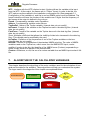
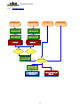
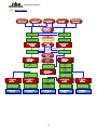
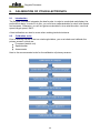
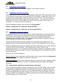
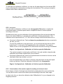
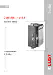
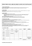
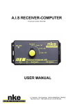
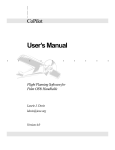
Regatta Processor
USER MANUAL
and
INSTALLATION GUIDE
1
Regatta Processor
2
Regatta Processor
Table of contents
1. INTRODUCTION
4
2. THE TOPLINE NETWORK
4
3. THE REGATTA PROCESSOR
4
4. ARCHITECTURE OF THE INSTALLATION
6
5. INSTALLATION OF THE REGATTA PROCESSOR
6
5.1
5.2
5.3
5.4
5.5
5.6
5.7
5.8
INITIAL SYSTEM INSTALLATION
INTEGRATING THE PROCESSOR IN AN EXISTING INSTALLATION
INTEGRATING THE R EGATTA PROCESSOR IN YOUR NKE BUS
ETHERNET CONFIGURATION
CONNECTING TO THE R EGATTA PROCESSOR:
CONNECTION TO THE TOPLINE BUS
NMEA 1 CONNECTOR OR 3D SENSOR
NMEA 2 CONNECTOR
6. REGATTA PROCESSOR CONFIGURATION
6.1
6.2
6.3
CONFIGURATION OF THE INSTALLATION FILE
CONFIGURATION OF THE CONSTANTS CALIBRATION FILE
CONFIGURATION OF THE VARIABLE.CSV FILE
7. ALGORITHM OF THE CALCULATED VARIABLES
7.1
7.2
7.3
SPEED VARIABLES
ATTITUDE VARIABLES
W IND VARIABLE
8.1
INTRODUCTION
8.2
CALIBRATION ORDER
8.3
CALIBRATION OF THE COMPASS
8.4
CALIBRATION OF THE HEEL AND PITCH
8.5
CALIBRATION OF THE BOAT’S SPEED
8.5.1
Speedometer calibration method (simple calibration):
8.5.2
Description:
8.5.3
Linearisation of the surface speed according to the boat’s heel
8.6
CONFIGURATION OF THE DRIFT
8.6.1
With a drift calibration coefficient:
8.6.2
Using a correction table:
8.7
CALIBRATION OF TRUE WIND SPEED
8.8
CALIBRATION OF APPARENT WIND ANGLE
8.9
CALIBRATION OF TRUE WIND ANGLE
9. PERFORMANCE AND SPEED POLAR
10.
13
14
15
16
20
20
20
21
21
21
21
22
22
23
23
24
24
25
26
28
HOW TO READ A SPEED POLAR
HOW TO READ A SPEED POLAR CURVE
PERFORMANCE VARIABLES
28
29
30
APPENDIX A
34
10.1 CONFIGURATION OF MY COMPUTER FOR THE FIRST CONNECTION TO THE PROCESSOR
10.1.1
Connection of the Regatta Proc essor to your computer
10.1.2
Configuration of the net work connection under Windows XP
10.1.3
Configuration of the net work connection under Windows Seven
10.1.4
Testing the connection with the Regatta Processor
10.2 USE OF THE “V ERBOSE” MODE
11.
13
17
18
19
8. CALIBRATION OF YOUR ELECTRONICS
9.1
9.2
9.3
7
7
8
9
10
11
11
12
FREQUENTLY ASKED QUESTIONS
34
34
34
35
38
39
41
3
Regatta Processor
1.
INTRODUCTION
We thank you for showing your confidence in the nke brand by choosing the Regatta
Processor. You have just acquired an onboard calculator at the heart of an architecture
that provides the skipper, autopilot, onboard data processing system, analysts, with the
most accurate, noiseless and responsive information required for performance.
This user and installation manual includes the information that will allow you:
-
to install the Regatta Processor and initialise the system.
-
to setup the Regatta Processor and sensors.
-
to familiarise yourself with your Regatta Processor and master all of its functions,
-
to achieve optimum performances with your boat.
2.
THE TOPLINE NETWORK
The Topline network is made up of sensors and displays connected together by a 3-wire
link (0V earth braid, +12V white wire, Data black wire). Data is emitted and received along
the "DATA" wire.
The displays have a variable address of between 1 and 20. The sensors have a fixed
address of between 21 and 210. The network is managed by one of the displays, which is
designated as "MASTER" when the installation is first started up and which takes the
address "1".
When the "MASTER" is switched on, it interrogates all of the possible addresses to find
out where those displays and sensors that are effectively connected to the network
(CREAT LISTE) are to be found and displays the variable addresses of those displays.
When this listing phase is complete, the "MASTER" only continues to interrogate those
channels that have responded to its interrogation. The "MASTER" also interrogates the
address "0" (non-numbered display) at regular intervals. If a slave display gives a specific
response to this interrogation, it will be allocated an address then dynamically inserted into
the network.
3.
THE REGATTA PROCESSOR
The Regatta Processor meets the objectives in terms of:
1. Performance:
Performs accurate and high speed (25Hz) measurements of wind (apparent, real),
surface and bottom speed, attitude.
Measures accelerations and the hull’s attitude (magnetic heading, angles,
accelerations, gyration speeds, magnetometric vector)
Accurately calculates the true wind by compensating the measurements from the
wind sensor with the boat’s kinematics, and by using by correction tables.
4
Regatta Processor
2. Speed:
Manages fast data flows (high responsiveness of the sensor measurements,
autopilot actions and displays).
Interfaces at high frequency with the onboard data processing system to the main
navigation software (via the SailNet protocol over IP and various gateways).
Compatible with Proteus systems.
3. Safety and reliability:
Integrated safety: various levels of fail safe and fault modes possible which allow
the availability of basic functions with no Regatta Processor.
Use of the lightest possible Linux operating system, ensuring real time operation
with no disruptive software task (nor virus), and with no moving mechanical parts
(fan, hard drive…)
Self-diagnostic log can allow to quick understanding of a possible malfunction.
4. Standardisation:
Definition of simple and open formats and protocol for:
the logs of variables
variables exchange protocols via fast RS232/NMEA0183 or IP.
the adjustment of linear calibrations, filters, alarms and nonlinear, polar calibration
files.
Use of the same variables definition basis at all levels: in the external Gyropilot
Graphic display, Regatta Processor, logs of variables, compatible navigation
software (Expedition), Network, post-processing software (Excel), diagnostic
software (Toplink…).
5. Post-processing:
Diagnostic and modelling via internal data logging.
6. Openness:
Possible customisation/translation, partial or total, of the variables (and displays on
the GyroPilot Graphic display, Deckman, Tools).
Open “SailNet” variables exchange IP protocol (Linux/Windows library and
examples provided, simultaneous use of several boats and/or navigation software
possible).
7. Upgradability:
Simple updating of the Regatta Processor software via Internet
Use of Topline peripherals with Flash memory for onboard updating with the Toplink
PC software.
8. Energy:
Allows the onboard computer to be left on standby and the performance data to be
shown on the nke displays.
The wind data supplied to the pilot by the Regatta Processor are faster and less
noisy. Thus this allows the pilot’s helm turns to be optimised, and consequently the
pump motor’s consumption to be reduced.
5
Regatta Processor
4.
ARCHITECTURE OF THE INSTALLATION
The equipment shown in the following diagram is for information only, and does not
represent the equipment of your installation.
5.
INSTALLATION OF THE REGATTA PROCESSOR
This chapter of the manual shows you how to install the Regatta Processor. It also
explains how to initialise the processor associated to the Topline bus and all of its
components.
IMPORTANT:
- Read this user guide entirely before starting the installation.
-
The electrical connection on the TOPLINE bus must be performed with terminal box
90-60-417.
-
Always swith off power before removing or adding components.
6
Regatta Processor
5.1
Initial system installation
Install all the components of the nke bus without the Regatta Processor, referring to the
manual of each nke sensor, display or interface. Make a Gyropilot Graphic display the
bus master.
Now refer to the paragraph “Integrating the Processor in the nke bus”
5.2
Integrating the processor in an existing installation
The first step consists in updating all the elements of your Topline bus. In order to do this,
you must either use the “Toplink2” software or return your equipment to nke’s After Sales
Service.
The up-to-date firmware and database are available on nke ftp server
(ftp://83.206.237.67/cgi-bin/browse?share=prohr&path=/Toplink ).
List of software versions compatible with the Regatta Processor:
Element type
Display
Display
Display
Display
Interface
Interface
Interface
Interface
Interface
Sensor
Sensor
Sensor
Sensor
Sensor
Sensor
Sensor
Sensor
Sensor
Sensor
Sensor
Sensor
Element designation:
Performance
Gyropilot Graphic
SL50
TL25
Wired remote control
Radio receiver
NMEA output interface
NMEA input interface
Diagnostic tool: Toplink 2
Single battery controller
Double battery controller
3D Sensor
Potentiometric mast angle
HR 100 barometer
Ultrasonic Speedo Starboard/Port/Centre
Single depth-finder log interface
Double depth-finder log interface
Carbowind HR
AG HR
AG Flash
Fluxgate compass
Software version
or above
Limited
V2.7
V1.3
V1.5
V2.1
V2.4
V1.2
N.A.
Not compatible
Not compatible
N.A.
V1.4
V1.0
V1.5
Limited *
Not compatible
V1.8
V1.8
V2.5
N.A.
* Speed yes, Depth no.
Once all the elements updated, switch on the bus and check that everything is in working
order. Favour a Gyropilot Graphic display as Topline bus master.
It will be easier to switch to the bus fitted with the Regatta Processor.
7
Regatta Processor
5.3
Integrating the Regatta Processor in your nke bus
Now that all the sensors, displays and interfaces are updated and compatible with the
Regatta processor, you must get your installation ready to receive the Regatta processor.
Indeed the latter will act as master so there must be no other master on the current bus.
In order to do this, you must reset the master Gyropilot Graphic for a new address to be
assigned to it:
Using the Page key on the Gyropilot Graphic, select the Main menu page,
then using the browser
1
1
, select configuration then initialize address,
press Ent,
the following message appears “to force the address to 0, press Ent”, press Ent,
the following message appears “Gyropilot address: 0”
Switch off the bus, connect the Regatta processor with its 3D Sensor compass, if
you use this sensor, to the bus and switch on the unit.
Wait for the processor and bus to finish loading. (See LED state table)
The message “the display has no address” appears on the Gyropilot Graphic.
It is not initialised.
One must wait until the whole system has started for an element of the bus to be
able to request an address from the Processor. Wait until the data show up on the
TL25 and wait 10 seconds.
Using the Page key, select the Main menu page,
then using the browser
1
1
, select configuration then initialize address,
press Ent,
the following message appears “to obtain an address, press Ent”, press Ent,
the following message appears “list” and the Gyropilot takes an address. The
new address of the Gyropilot is temporarily shown on the screen.
exit this menu by pressing Page.
8
Regatta Processor
LED state
LED unlit
LED blue
1 flash
▲ 1s period
Operating state or corresponding fault
- Processor power off or out of order.
- Regatta Processor operating normally
- the self-control internal to the application is correct
Flashing, 0.5s
- Regatta Processor starting
period
▲▲▲▲▲▲▲
Flashing, 1s period - The operating system is starting
▲▲▲▲▲▲▲
- Problem, contact your distributor
Continuous
- Upon powering up: Ext3 formatting check
5.4
Ethernet configuration
The way you will connect your Processor to your computer or Tablet PC will depend on
your boat’s network installation and/or on the presence of the WiFi or Bluetooth option.
Direct Ethernet connection:
The network cable supplied with your Regatta Processor is a crossover cable that allows
your computer to be directly connected to the Processor.
RJ45 network crossover cable
Ethernet connection via a network:
The network cable supplied with your Regatta Processor is a crossover cable. It can be
used with the most recent Ethernet Switches. Check that your Switch is compatible with
the crossover cables, otherwise use a straight-through cable.
9
Regatta Processor
5.5
Connecting to the Regatta Processor:
Before trying to connect, your computer must be correctly configured. This connection will
enable you to communicate via ftp, http, and the Sailnet dll. Thus you will have access to
the calibration tables, to the log files that allow faults to be diagnosed and to the software
update.
When you receive your Processor, it is configured at the address 192.168.0.232 by default
and the connection settings are:
Login : root
Password : pass
Make sure you check the following points before attempting a connection:
That the Processor’s blue “control” light flashes
On the PC’s RJ45 Ethernet connector: Yellow LED flashing if activity / Green LED lit
if hardware connected
On the Firewall, enable all ports at the address 192.168.0.232
If you use a proxy, in your Web browser, in the advanced connection settings, proxy
settings, add “192.168.0.232” in “Do not use the proxy for addresses”.
The HR processor does not integrate a DHCP server; also, if you use a point-topoint Ethernet connection and you do not have an IP address automatically
assigned via DHCP, you must freeze the PC’s IP address with an address of the
type 192.168.0.X, with X different from 232, because it is the Regatta Processor’s
default address. (See appendix A Connection to the Regatta Processor)
With the http protocol:
Open your browser (Internet Explorer, Firefox etc.) and type the following command in the
address bar: http://192.168.0.232 then validate by pressing “Enter” (validate on the
connection button if the browser asks you).
You are then directed to the Regatta Processor’s configuration page.
With the FTP protocol:
To connect to the FTP server from your computer, without the software asking you for a
connection login and password, type the following address in an explorer window or in the
network favourites:
ftp://root:[email protected]
You can access the internal USB key at the following address:
ftp://root:[email protected]/var/usbdisk/
You can access the Regatta Processor’s configuration files at the following address:
ftp://root:[email protected]/mnt/Flash/process/
10
Regatta Processor
With the Telnet protocol:
Click on Start / Run. Type telnet 192.168.0.232 and validate.
A DOS window appears, you are asked for a user name and password for safety
purposes, so as to restrict access only to authorised users.
Login : root
Password : pass
Ou Login : p (no to have to type in a password)
If you have problems connecting to your Regatta processor, refer to the paragraph
“Configuration of my computer for the first connection to the processor”
5.6
Connection to the Topline bus
The Topline bus must be connected to the Processor’s Topline connector. This bus also
supplies the processor with 12 volts.
Cable: twisted pair with aviation-type braid.
Connector: Binder brand, 5 pts series 620.
Wire colour
Potential
Pin out
Blue
Topline data
3 & 5 together
White
+12V IN (OUT sur Topline 2) 4
Braid
Ground
1
Not connected +5V OUT
5.7
2
NMEA 1 connector or 3D sensor
This connector can feed and receive data as per the NMEA protocol or the data from the
3D Sensor.
The inertial 3D sensor is prewired and supplied with 5V by the HR Processor.
Cable: 3 wires + aviation-type braid
Connector: Binder brand, 5 pts series 620.
Wire colour
Potential
Pin out
Blue
TX processor
5
White
RX processor
3
Orange
+5V OUT
2
Braid
Ground
1
Not connected +12V OUT
4
11
Regatta Processor
5.8
NMEA 2 connector
This connector can feed and receive the data up to 115Kb, for example from a high
frequency GPS, but it can have several uses (bidirectional, non opto -isolated NMEA
connection with the navigation PC, bidirectional link with a WTP, calibration aerial,
nmea0183 sensor…).
To configure this port, see paragraph 5.1 Configuration of the installation file .
Cable: 3 wires + aviation-type braid
Connector: Binder brand, 5 pts series 620.
Wire colour
Potential
5pts pin out
DB9pts pin out
Blue
TX processor = RX NMEA 5
2
White
RX processor = TX NMEA 3
3
Braid
Ground
1
5
Orange
+12V OUT
4
Isolated
2
Not connected
Not connected +5V OUT
The NMEA input identifies the frames below. The process is thus able to create more than
40 NMEA channels on the Topline bus of your installation. These NMEA channels do not
have sub-channels.
The identification of the channels is automatic. The NMEA channels created by the
gyrographic pilot maintain priority over the NMEA input of the Regatta Processor.
Code
Description of the NMEA frame
Possible associated variables
Latitude,LatDegMin,Longitude,LonDeg
Min
StatusGPS
Latitude, LatDegMin, Longitude,
LonDegMin
StatusGPS
GGA
Latitude, longitude and time
GLL
Latitude, longitude, time and quality index
ZDA
Date and time
UTC Date and Time
RMC
Latitude, longitude, date, time, bottom
heading, bottom course and
compass correction: as minimum data;
UTC Date and Time
VTG
Ground speed and course
SOG and COG
HDG
Magnetic heading, deviation and variation
PilMagHdg, MagHdg
HDM
Magnetic heading, deviation and variation
PilMagHdg, MagHdg
HDT
True heading
TrueHdg
KHV
Attitude
Heel, Trim, PilMagHdg, MagHdg
SDT
Protéus strain gauges (stresses)
JaugeX
SST
Protéus strain gauges (calibration and status)
CA_JaugeX, OF_JaugeX, ID_JaugeX,
Frq_JaugeX, Qlt_JaugeX, Hrs_JaugeX
12
Regatta Processor
6.
REGATTA PROCESSOR CONFIGURATION
This chapter is designed to help you configure your Regatta Processor with your
electronic installation and onboard data processing system.
6.1
Configuration of the installation file
A text file can be found at the following address:
http://192.168.0.232/ then click on “Configuration of the installation”
This file allows you to configure the parameters of the Regatta processor. It is divided into
sub-paragraphs.
IMPORTANT
By default, this file is properly configured. You can modify it to customize your
installation.
Do not forget to save the changes by pressing “Save File”. Once the file is saved,
the Regatta processor must be restarted for the changes to be taken into
account, using the “Restart” command, accessible from the home page.
Damping
PilBtSpdDamp : This filtering allows the speedometer speed to be filtered. The filtering
then applied is that of the display filtering which can be adjusted from the Gyropilot
Graphic. This option must not be validated with Ultrasonic Speedo units. It can be useful if
you use vaned rotor speedometers, which are often noisy.
AppWindCorDamp : This option validates, or not, the on-display filtering of apparent wind
speed and angle (VVA_Cor and AVA_Cor) before application of the true wind tables. This
filtering is useful for debugging but has no influence on the calculations of true wind.
Language
Language: Allows language selection for the labels, either in French or in English. You
can replace English with another language, but in orde r to do this, you must open the file
“variables.csv” and replace each name in the column “En10Name” with a new one. The
new name must not be more than 10 letters long.
0 = French
1 = Secondary language, English by default.
Compute
Performance: This option allows the calculations to be validated, or not, and to display the
performance variables.
UseSOG : Use Speed Over Ground for wind calculation and autopilot algorithm.
MotionWindComp : Calculation of the dynamic compensation that allows the gyrations in
the data coming from the anemovane to be corrected.
0 = No dynamic compensation.
1 = Dynamic compensation with the raw data from the anemovane. (Mode to be used with
AG HR > V1.7)
13
Regatta Processor
2 = Dynamic compensation with the filtered data from the anemovane. (Mode to be used
with AG HR < V1.7 and AG Classic)
GyroPiWindComp : Enable the kinematics compensed AWA in the horizontal plan.
Datalog
ValidDatalog : Enable data logging of all the data on the internal USB key.
3Dhull
Valid3DH : Enable the use of the hull 3D Sensor.
NmeaIn
ValidNmeaIn : Enable the NMEA input on the NMEA/GPS port
ValidUdpNmeaIn : Enable the UDP input between the onboard PC and the processor. For
this mode to operate, ValidNmeaIn must be at “n”.
UdpNmeaInPort : Incoming port number for the UDP li nk.
NmeaOut
ValidNmeaOut : Enable the NMEA output on the NMEA/GPS port
NmeaOutBaudrate : NMEA/GPS port baud rate. This baud rate is also valid for the NMEA
input.
ValidUdpNmeaOut : Enable the UDP output between the onboard PC and the processor.
For this mode to operate, ValidNmeaOut must be at “n”.
UdpNmeaOutIP : IP address of the recipient PC.
UdpNmeaOutPort = Outgoing port number for the UDP link.
SailNet
ValidSailNet : Enable the Sailnet dll which allows a PC to communicate with the Regatta
processor. It is independent from the UDP connection. However, it is essential for the use
of the calibration aid software.
SailNetOutIP : IP address of the recipient PC.
SailNetOutPort : Outgoing port number for the IP link.
SailNetInPort : Incoming port number for the IP link.
6.2
Configuration of the constants calibration file
A text file can be found at the following address:
http://192.168.0.232/ then click on "Calibration of the constants ”
This file allows you to set and adjust some constants that cannot be accessed from a
Gyrographic Pilot. It is divided into sub-paragraphs.
IMPORTANT
By default, this file is properly configured. You can modify it to customize your
installation.
Do not forget to save the changes by pressing “Save File”. Once the file is saved,
the Regatta processor must be restarted for the changes to be taken into
account, using the “Restart” command, accessible from the home page.
14
Regatta Processor
Dampings
USspdDampStbd : Internal filtering of the starboard Ultrasonic Speedo. This filtering
allows the speedometer’s responsiveness to be improved. A value of 31 allows you to
return to the original filtering. If filtering is too low, the Ultrasonic Speedos can give in at
high values.
USspdDampPort : Internal filtering of the port Ultrasonic Speedo.
SogCogDamp : Filtering of the display of bottom speed and heading provided by the
processor’s NMEA input.
TrueWindDamp : On-display filtering of true wind data.
MastAngDamp : On-display filtering of mast angle.
Constants
HdgOff : Magnetic heading offset. It can be added to that which can be accessed from the
Gyrographic pilot. It is useful when adding an offset to the nearest hundredth.
MastRotOff : Mast angle offset. It can be added to that which can be accessed from the
Gyrographic pilot. It is useful when adding an offset to the nearest hundredth.
WindShear : This is an offset that allows the shear angle of true wind to be compensated.
AWSOff : Offset of apparent wind speed in knots.
FailSafeBS : Coefficient that allows the simulation of a backup surface speed in relation to
the apparent wind speed. (Backup surface speed = Coef*VVA)
MotionWindComp
WindVaneHigh : Height of the anemovane in relation to the boat’s centre of rotation.
6.3
Configuration of the variable.csv file
This file allows the customisation of the displa y and, at the NMEA output, of the Topline
bus variables.
A text file can be found at the following address:
ftp://192.168.0.232/mnt/flash/processor/SailNet/
IMPORTANT
It is recommended to backup this file before modifying it.
Num: Variable number.
Help : English description of the function of the variable.
En10Name : English name of the variable.
En3Unit : English unit of the variable.
Aide : French description of the variable.
Fr10Nom : French name of the variable.
Fr3Unit : French unit of the variable.
View : Displays, or not, the variable on a Gyrographic pilot.
Group : Name of the group to which the variable belongs.
ExpedName : Name of the variable in Expedition.
Deckman : Name of the variable in Deckman.
15
Regatta Processor
WTP : Interface with the WTP’s fastout output. A letter defines the variable at the input
from the WTP. At the output, the frames are in “PNxxx” format. In order to do this, the
WTP option must be enabled in the installation configuration file (See paragraph 5.1
Configuration of the installation), and the in and out NMEA option must be disabled. The
frame’s identifier will have the number of the variable over 3 digits. And the frequency of
the frames at the output is defined in the column.
Exped : Corresponding variable under Expedition.
Adrena : Corresponding variable under Adrena.
ToplineDef : Name of the Topline variable. (Internal data, do not modify)
IntFormat : Format of the variable on the Topline bus and in the data log files. (Internal
data, do not modify)
FloatForm : Format of the variable on the Topline bus and in the data log files. (Internal
data, do not modify)
Zoom: Multiplier coefficient that allows the visibility of data to be increased in the data log
files. (This variable can be modified by the user)
HzTopline : Definition of the frequencies of use of the Topline variables on the bus.
(Internal data, do not modify)
NmeaIN : Column of configuration of the standard NMEA priorities. The order of NMEA
variables used on the Topline bus, which come from the NMEA/GPS input, can be
modified. In order to do this, the identifier of the NMEA frame (3 letters), separated by a
space, simply need to be placed in the desired order.
Custom : Authorises, or not, the use of a custom variable from an NMEA input and an LUA
file.
7.
ALGORITHM OF THE CALCULATED VARIABLES
This chapter describes the algorithms of the main variables used for the calculation of true
wind and the data for the autopilot. These algorithms will help you understand the system.
The logos used in the diagrams of this chapter are explained below.
Sensor Mesurement
Table of correction
Or calculation
Apparent wind
speed
(MW_speedHR)
Variable to display
Variable
16
Manual
or
Autom atic
Selection
Regatta Processor
7.1
Speed variables
ECHOSPEED PORT
ECHOSPEED TRIBORD
CA_VitSuBa
Port Surface Speed
Linear Calibration
SOG
Coefficient x AWS
CA_VitSuTr
StarbordSurface Speed
Linear Calibration
OF_VitSuBa
Surface Speed Offset
Port
OF_VitSuTr
Surface Speed Offset
Starbord
PortUsBs
StbdUsBs
2 Hz
2 Hz
Heel tack
selection
AW A tac k selection
Speed Calibration
According to the heel
BtSpdHeel.txt
Backup Selection
Boat Speed
_FI_VitSurf
Surface
Speed Damping
8 Hz
Surface Boat speed
(Boatspeed)
Surface Boat Speed pilot
(BtSpdPil)
17
Regatta Processor
7.2
Attitude variables
Magnetic Declination
File
GPS
3D SENSOR HULL
Magnetic
Compensation
f
3DsensorMapper.exe
Magn etic
Declination
(MagDecl)
Heading
Compensation
Attitude calculation
Hull Trim Offset
Heel Offset
(OF_Gite)
Pil ot Magnetic Heading
(Pi lMagHdg)
25Hz
Heading Attitude, Heel, trim
Damping
(FI_Cap)
Cap Magnetic Heading
(MagHdg )
True Headin g
Ge ograp hic North
(TrueHdg Pil)
Measure d Heel Angle
(MeasHeel)
25Hz
Heading Attitude, Heel, trim
Damping
(FI_Cap)
True Headin g
(TrueHdg )
(OF_Trim)
25Hz
Heading Attitude, Heel, trim
Damping, Tangag e
(FI_Cap)
Heel l
(Heel)
18
Hull Attitude
(3DH_Acc, 3DH_Gir,
3DH_Mag)
Hull Pitch angle
(3DH_Pitch)
25Hz
Heading Attitude, Heel, trim
Damping
(FI_Cap)
_
Trim
(Trim)
_
25Hz
Regatta Processor
7.3
Wind variable
Apparent wind s peed
Measured Mast Angle
(MW_speedHR)
(MesMastRot)
25Hz
25Hz
Measured Heel Angle
(MeasHeel)
25Hz
Apparent Wind Angl e
Hull Pitc h angl e
(3DH_Pitc h)
(MW_angl eHR)
25Hz
25Hz
Attitude c oque
(3DH_Acc, 3DH_Gir,
3DH_Mag)
25Hz
Calculation of the
dynamic compensation
Calculation of the
dynamic compensation
Height of the MHU to the
Apparent wind calculation
Boat’s center of rotation
To a horizontal referential
Apparent wind calculation
To a horizontal referential
Corrected M easur ed
Wind Speed
(CMWS)
Boat Speed
pilot
(BtSpdPil)
25Hz
8Hz
Corrected M easur ed
Wind Angle
(CMWA)
25Hz
True wind speed
Calculation
True wind angle
calculation
Leew ay Correcti on
(Leeway)
Unc orrected
True Wind Speed
(Orig_TWS)
Course
(Course)
12.5Hz
Unc orrected
True Wind Angl e
(Orig_AVR)
12.5Hz
25Hz
True Wind Speed
Table
(Adjv t.d)
True Wind Angle
True Wind Direction
Calculation
Unc orrected
True Wind Direction
(Orig_TWD)
Apparent Wind Speed
Retro Calculation
12.5Hz
True Wind Speed
Pilot
(TWS_Pilot)
PilotHR True Wind damping
(TW_PilDamp)
True Wind Speed
(TW_Speed)
12.5Hz
Table
(Adj wa.d)
WindShear
correction
(WindShear)
Apparent Wind Angle
Retro Calculation
12.5Hz
Apparent Wind Speed
pilote
(VVA_Pilote)
Apparent Wind Angle Damping
(FI_AVA1/ FI_AVA2)
Apparent Wind Speed
(AW_speed)
12.5Hz
True Wind Angle
Table
(Adj wa.d)
WindShear
correction
(WindShear / Off_DVR)
True Wind Direction
(TW_Dirn)
19
Apparent Wind Angl e
Pilot
(PilotAWA)
Apparent Wind Angle Damping
(FI_AVA1/ FI_AVA2)
Apparent Wind Angl e
(AW_angle)
12.5Hz
True Wind Angl e
Pilote
(TWA_Pilot)
True Wind Angle Damping
(TW_PilDamp)
True Wind Angl e
(TW_Angl e)
Regatta Processor
8.
CALIBRATION OF YOUR ELECTRONICS
8.1
Introduction
The Regatta Processor integrates the boat’s polar in order to recalculate and display the
performance data. In order to do this, you must have calibrated data for wind, boat speed
and compass. Otherwise, you will not get accurate data for true wind direction, true wind
speed, target speed, VMG…
A bad calibration can lead to errors when making tactical decisions.
8.2
Calibration order
Prior to entering values in the true wind angle tables, you must check and calibrate the
primary sensors, which are:
Compass (Inertial unit)
Speedometer
Anemometer
Here is the recommended order for the calibration of primary sensors:
20
Regatta Processor
8.3
Calibration of the compass
For this sensor, refer to the calibration chapter of the sensor’s manual.
8.4
Calibration of the heel and pitch
These parameters can be calibrated using a digital or laser level. Place the reference level
on the reference surface given by the architect and check that no large metal mass, such
as a pontoon or a cargo ship, is withi n 20 metres of the 3D Sensor. The boat must be
balanced, check that no heavy object such as sails, anchor… is on one side of the boat,
thus leading it to heel. The best option is to perform this test empty, without sails, no
victualling… For this test, the sea must be flat.
Enter the calibration offsets in the menus of the Gyrographic:
Page ► Configuration ► Calibration ►Heel ►Offset
Page ► Configuration ► Calibration ►Trim angle ►Offset
8.5
Calibration of the boat’s speed
The speed measured at the boundary layer is turbulent and depends on the type of boat
and its shape. 60-foot type monohulls with flat bottom and bilges present the heel with a
wet surface, the longitudinal axis of which is not the boat’s longitudinal axis (like a
catamaran with non parallel hulls). The speedometer cannot have an alignment with the
correct advancement axis both flat and heeled.
Vaned rotor speedometers measure speed in an accelerated and disturbed flow. The
measuring error can be increased according to the heel. The measurement is not linear.
Ultrasonic speedometers measure a speed around ten centimetres from the hull. The flow
is laminar and a lot less disturbed. The measurement is linear. However, the
measurement can be 1 to 2% optimistic with strong heel in relation to a calibration carried
out flat because of the accumulation of errors in the alignment and increasing thickness of
the boundary layer.
There are two levels of calibration:
Simple calibration with a calibration coefficient that can be entered using the Gyrographic
Pilot. In this case, the coefficient is entered in the sensor.
Advanced calibration which uses calibration tables by speedometer and a calibration table
for the boat speed according to the heel. The tables are kept and used by the Regatta
Processor.
8.5.1 Speedometer calibration method (simple calibration):
The most optimum method consists in making back and forth trips, ideally close to normal
sailing speed and opposite heading so as to eliminate the current. The boat must move
forward in a straight line and start its “run” with stabilised speed and heading. Both tacks
must have approximately the same length. The reference is the bottom speed which is
given by the GPS. The calibration is made according to the average of the bottom speed
and the average of the surface speed.
21
Regatta Processor
To calculate the calibration coefficient, you can use the data logged on the internal USB
key by extracting the useful parts and using the formula below. Or by using a navigation
software which has a calibration tool.
8.5.2 Description:
You can enter a calibration coefficient in the Gyrographic Pilot and/or complete the
linearization tables of surface speed and/or complete the table of surface speeds
according to the heel.
Simultaneously carry out the calibration of both speedometers flat and use the data log
files on the internal USB key to calculate the coefficients of each speedometer. This
calibration can be performed at 5, 10, 15kt, with an average coefficient deduced from it.
If the boat is fitted with two Topline ultrasonic speedometers directly connected to
the bus, you can:
To enter the coefficient in the right sensor, you must force the heel with an offset
higher than 3° on the side of the speedometer to be configured. The negative
values of heel on the Gyrographic Pilot indicate that the boat is heeling to starboard.
Page ► Configuration ► Calibration ►Surface speed ►Calibration
The easiest consists in entering the coefficient in the right variable using the nke
calibration aid software supplied with your processor.
If the boat is fitted with two vaned rotor speedometers connected to the bus via the
dual depth-finder log interface, you can:
Force the speedometer you wish to configure using the switch on the dual depthfinder log interface. Enter the calibration coefficient in the Gyrographic:
Page ► Configuration ► Calibration ►Surface speed ►Calibration
8.5.3 Linearisation of the surface speed according to the boat’s heel
Some shapes of hulls of heeling boats disturb the hydrodynamic flow more profoundly.
You may be forced to correct the surface speed according to the boat’s heel angle.
In order to do this, you have the calibration table “BtSpdHeel.txt” at your disposal in the
Regatta processor.
22
Regatta Processor
Heel
BsCal
-40.0
-25.0
-10.0
0.0
10.0
25.0
40.0
0.960
0.980
0.990
1.000
0.990
0.980
0.960
Values are negative when the heel of mast is on starboard.
The principle is the same as that for the calibration of the speedometers, back and forth
trips must be made at constant speed and at different constant heel. The coefficient
obtained must be entered in the calibration table.
8.6
Configuration of the drift
The calibration of the drift angle is not easy to quantify, calculate or measure. It depends
on the shape of the boat, on the presence or not of drift, foil, keel pendular or not… Its
measurement can also be erroneous with the current.
The drift angle is defined between the boat’s longitudinal axis and the advancement vector
in relation to the surface. But the boat moves forward along the longitudinal axis of the
wetted surface which, at the heel, forms an angle with the boat’s longitudinal axis.
There are two ways to configure the drift of your boat:
8.6.1 With a drift calibration coefficient:
This coefficient can be accessed on the Gyrographic pilot
Page ► Configuration ► Calibration ►Drift angle ►Calibration
The formula used to calculate the drift is:
Drift in degrees, heel in degrees, surface speed in knots, drift coefficient in °/kt². The
coefficient is a general value that will be applied to all navigation conditions. Thus you
must apply an average value to this coefficient for all conditions or change the coefficient
depending on the force of the wind. In the polars provided by the architect, you will find the
drift angle according to the surface speed and the heel of your boat. Recalculate the
coefficients using the formula below and calculate an average value.
23
Regatta Processor
8.6.2 Using a correction table:
If you have the drift angles provided by the architect of your boat, you can directly enter
the values in the drift polar which is in the Regatta processor.
If you do not have data from the architect, you can try and measure it by performing a
series of measurement using various methods:
Measure the angle of the boat’s wake and the boat’s longitudinal axis using an
bearing compass.
In the data logs, compare bottom heading and true heading.
Caution: for all of these measurements, there must be no current! Otherwise the
measurements will be distorted.
Link to the calibration table for true wind speed:
http://192.168.0.232/ then click on "Correction of true wind speed"
Below is an example of drift polar in the Regatta processor. The upper line shows the true
wind speed in knots, the left-hand column includes the true wind angles in degrees and the
drift coefficients are given in °/kt² in the body of the table.
TWA
4
6
8
10
12
14
16
20
25
30
33
1.87
1.76
1.57
1.37
1.30
1.28
1.32
1.44
1.58
1.73
36
1.82
1.75
1.51
1.33
1.27
1.27
1.34
1.45
1.60
1.75
39
1.82
1.72
1.45
1.30
1.25
1.28
1.35
1.47
1.62
1.75
50
1.93
1.65
1.36
1.24
1.25
1.33
1.39
1.52
1.67
1.80
60
1.87
1.63
1.40
1.21
1.27
1.35
1.41
1.51
1.63
1.74
70
1.73
1.64
1.47
1.23
1.23
1.28
1.33
1.43
1.53
1.64
80
1.81
1.65
1.10
1.37
1.17
1.20
1.24
1.32
1.41
1.49
90
1.60
1.40
1.11
1.10
1.31
1.14
1.15
1.20
1.25
1.30
105
1.56
1.42
1.29
1.08
1.03
1.06
1.25
0.98
0.99
0.98
120
1.45
1.33
1.18
0.97
1.19
0.98
0.90
0.89
0.77
0.65
135
1.58
1.41
1.31
1.23
1.11
0.92
0.81
0.77
0.58
0.48
140
1.59
1.43
1.33
1.28
1.20
1.08
0.88
0.68
0.51
0.41
150
1.58
1.71
1.42
1.37
1.29
1.25
1.18
0.89
0.46
0.31
165
1.59
1.69
1.48
1.46
1.44
1.54
1.42
1.14
0.84
0.52
(Caution: this calibration table is not active in the of Feb 6, 2009)
8.7
Calibration of true wind speed
The measurement from the anemometer at the mast head, even at the tip of a carbon pole
one metre from the mast head, can be noisy. Before the wind, the mainsail, high and open,
accelerates the wind. The heel also influences the measurement of wind speed.
24
Regatta Processor
Deactivate the table of true wind speed during the calibration outputs so as to work on the
original pre-table wind. Otherwise the corrections to be made will have to be added to the
values already entered in the table.
Link to the calibration table for true wind speed:
http://192.168.0.232/ , then click on "Correction of true wind speed"
Measuring procedure:
The true wind speed must be averaged at a stop, upwind then before the wind under a
number of wind force conditions distributed between 5kt and 30kt.
Below is an example of correction table for true wind speed in the Regatta processor. The
left-hand column shows the true wind speed in knots, the column named “v1” shows the
correction to be made in knots, column “a1” shows the angle for which a correction is to be
made. Similarly for “a2” and “v2” at crosswind points of sailing, and “a3” and “v3” at
downwind points of sailing.
5.0
10.0
15.0
20.0
25.0
30.0
35.0
50.0
8.8
v1
0.0
0.0
0.0
0.0
0.0
0.0
0.0
0.0
a1
44
38
36
37
39
41
42
42
v2
-0.3
-0.6
-0.9
-1.2
-1.5
-1.8
-2.1
-3.0
a2
93
96
95
93
96
98
100
100
v3
-0.6
-1.2
-1.8
-2.4
-3.0
-3.6
-4.2
-6.0
a3
141
153
154
148
152
155
158
158
Calibration of apparent wind angle
The calibration of the apparent wind angle allows all the rigging dissymmetries to be
corrected.
Thus in order to do this, it is imperative that during the calibration transfers, you have the
same adjustment of sail, backstay on both tacks, stay tension… The helmsman must steer
the boat using the dogvanes without looking at the data provided by the electronics, so as
to avoid being influenced. One should try and have a symmetry in surface speed and heel
between both tacks. The sails must be that of time. Do at least four tacks to compare and
validate the offset of shift of apparent wind angle.
Disable the table of true wind and reset wind shear to 0. The validation of true wind tables
is described in paragraph 5.1 Configuration of the installation file.
To measure the offset of apparent wind angle, you can either use the apparent wind angle
calibration tool of performance software like “Tactique” for example, or do your own
calculations by working on the data logged on the Regatta Processor’s USB key. That is to
say to use the tool of the software nke of assistance to the calibration. Or you can use the
tool of nke calibration aid software.
Caution! If you work with software like “Tactique” from Adrena, the offset is calculated
using the “apparent wind angle” variable. This variable is a back calculated datum of the
25
Regatta Processor
true wind angle variable, filtered for display. Thus the table of true wind must be disabled
and the wind shear reset to 0. And apply the offset obtained to the existing value if it is not
null.
On the other hand, nke calibration aid software works with the raw datum.
Apply the offset in the Gyrographic:
Page ► Configuration ► Calibration ►App. wind angle ►manual
If port AWA is > starboard AWA:
Add half the difference between port AWA and starboard AWA
If port AWA is < starboard AWA:
Subtract half the difference between port AWA and starboard AWA.
8.9
Calibration of true wind angle
The table of true wind angle allows the true wind angle to be corrected without looking for
the causes leading to angle errors, therefore it is a method that globally allows all the
repeatable errors (torsion, flow acceleration before the wind, anemovane) to be corrected.
To carry out the calibration of true wind, tacking manoeuvres must be performed and the
difference in the angle of true wind direction noted. It is preferable to carry out calibrations
with a wind that is relatively stable in direction. Over several navigations with true wind
speed conditions uniformly distributed between 5kt and 30kt.
26
Regatta Processor
Port TWD is > starboard TWD:
Add half the difference between port TWD and starboard TWD
Below is an example of correction tab le for true wind angle in the Regatta processor. The
left-hand column shows the true wind speed in knots, the column named “v1” shows the
correction to be made in degrees, column “a1” shows the angle for which a correction is to
be made. Similarly for “a2” and “v2” at crosswind points of sailing, and “a3” and “v3” at
downwind points of sailing.
0.0
5.0
10.0
15.0
20.0
25.0
30.0
35.0
50.0
v1
-7.0
-7.0
-3.0
-2.5
4.5
6.5
8.0
8.0
8.0
a1
44
44
38
36
37
39
41
42
42
v2
-2.0
-2.0
-1.0
0.0
1.0
1.0
1.5
1.5
1.5
a2
93
93
96
95
93
96
98
100
100
27
v3
4.0
4.0
3.0
1.0
-1.0
-1.0
-2.0
-2.0
-2.0
a3
141
141
153
154
148
152
155
158
158
Regatta Processor
9.
PERFORMANCE AND SPEED POLAR
The idea of performance consists in knowing, at each instant of navigation of your sail
boat, the theoretical speed of the latter according to true wind force and angle. This can
allow you to know if your boat is well set up or help you define the optimum angle to work
to winward and to down wind.
In order to do this, you use a speed polar. The latter is integrated into the processor via ftp
or the nke calibration aid software.
The speed polars are provided by the boat’s architect or manufacturer. If you do not have
them, you can make them yourself by noting the boat’s surface speed for every force and
angle of true wind.
9.1
How to read a speed polar
Below is an example of speed polar in the Regatta processor. The upper line shows true
wind speed in knots, the left-hand column shows the angles of true wind in degrees. The
boat’s speeds are given in knots in the body of the table.
TWA
4
6
8
10
12
14
16
20
25
30
33
1.87
1.76
1.57
1.37
1.30
1.28
1.32
1.44
1.58
1.73
36
1.82
1.75
1.51
1.33
1.27
1.27
1.34
1.45
1.60
1.75
39
1.82
1.72
1.45
1.30
1.25
1.28
1.35
1.47
1.62
1.75
50
1.93
1.65
1.36
1.24
1.25
1.33
1.39
1.52
1.67
1.80
60
1.87
1.63
1.40
1.21
1.27
1.35
1.41
1.51
1.63
1.74
70
1.73
1.64
1.47
1.23
1.23
1.28
1.33
1.43
1.53
1.64
80
1.81
1.65
1.10
1.37
1.17
1.20
1.24
1.32
1.41
1.49
90
1.60
1.40
1.11
1.10
1.31
1.14
1.15
1.20
1.25
1.30
105
1.56
1.42
1.29
1.08
1.03
1.06
1.25
0.98
0.99
0.98
120
1.45
1.33
1.18
0.97
1.19
0.98
0.90
0.89
0.77
0.65
135
1.58
1.41
1.31
1.23
1.11
0.92
0.81
0.77
0.58
0.48
140
1.59
1.43
1.33
1.28
1.20
1.08
0.88
0.68
0.51
0.41
150
1.58
1.71
1.42
1.37
1.29
1.25
1.18
0.89
0.46
0.31
165
1.59
1.69
1.48
1.46
1.44
1.54
1.42
1.14
0.84
0.52
The polar is a “.pol” file, it can only contain a maximum of 16 lines and 11 columns. The
separator between the columns is only tabulations. The separator between the integer and
decimal parts is the dot.
If these conditions are not observed, an error message is shown in the log file.
28
Regatta Processor
9.2
How to read a speed polar curve
Generally speaking, only the port tack part of the curve is represented, in general both
parts are symmetrical. (The example below represents the two parts)
The axis of the boat is vertical, the bow upward. The radii define the angles of true winds.
The concentric circles show the boat’s surface speeds in knots. Each curve corresponds to
a wind force.
Thus for every wind speed and true wind angle, the theoretical speed of the boat is
obtained by measuring the length of the speed vector.
To find the target speed as shown in the diagram below, simply trace a line perpendicular
with the axis of the boat’s surface speeds, and tangential to the polar at the strongest
point.
29
Regatta Processor
The speed polar is in the Regatta Processor at the following address:
ftp://192.168.0.232/mnt/flash/processor/tables/
In order to be taken into account, each modification of the polar requires the Regatta
Processor to be restarted. Every time the Regatta Processor starts, it recalculates all the
useful data and integrates them in its performance calculations. These data are available
on display.
9.3
Performance variables
The Regatta processor creates performance variables from the polar of your boat. You can
display them on the following nke displays:
Gyrographic Pilot
TL25
SL50
30
Regatta Processor
These variables will help you set up your boat. Display these data in real time will provide
you with information on the speed of your boat and the angle of true wind compared to the
theoretical data.
VMG :
Which means Velocity Made Good.
This is the best windward gain or the best heading/speed compromise, close-hauled
and downwind, for a given wind force. In fact, it is the projection of the boat’s speed
on the wind axis. It is a good indicator to sail a boat. The higher the VMG, the better
your work to winward.
Vent
VMG = True speed * cosine (True wind angle)
VMG
31
Regatta Processor
CMG :
Which means Course Made Good.
It is the best gain to the marker.
In fact, it is the projection of the boat’s speed on the direct course to the marker.
Close-hauled and downwind, this datum has little importance, tho ugh it can prove
useful at reach points of sailing.
Heading
Wind
CMG = True speed * cosine (Boat heading Target heading)
Tangential to the polar
CMG
Target speed:
It is the theoretical true speed of the boat at VMG. This variable is useful closehauled and downwind. For reach points of sailing, it is preferable to use the polar
speed.
Target true wind angle:
It is the optimum angle for the current wind conditions. This information allows the
optimum angle, close-hauled or downwind, to be known at any time for the current
wind conditions. It is the angle that provides the best VMG.
Polar speed:
This variable is calculated thanks to the boat’s speed polars according to the force
of the wind and the boat’s true wind angle.
This information allows the boat’s optimum speed to be known at any time for a
given true wind angle and speed.
Target speed %:
It is the percentage between the boat’s current speed and the target speed.
Polar speed %:
It is the percentage between the boat’s current speed and the polar speed.
VMG angle error:
It is the angle error in degrees between the boat’s current angle and the VMG’s
angle.
CMG angle error:
32
Regatta Processor
It is the angle error in degrees between the boat’s current angle and the CMG’s
angle.
Target VMG %:
It is the percentage between the projection of the boat’s current speed on the wind
axis and the target VMG.
Target CMG %:
It is the percentage between the projection of the boat’s current speed on the
course to the marker and the target CMG.
33
Regatta Processor
10. APPENDIX A
10.1
Configuration of my computer for the first connection to the processor
10.1.1 Connection of the Regatta Processor to your computer
Connect your Regatta Processor to your computer using the network crossover cable
supplied with the processor.
10.1.2 Configuration of the network connection under Windows XP
Here, the computer and Regatta processor are networked via an RJ-45 cable.
They each have an IP address that allows them to communicate with one another. The IP
address of the local area network may be fixed or dynamic. Since neither your computer,
nor the processor have a DHCP server that allows dynamic addresses to be provided,
your connection will use a fixed IP.
Defining a fixed local IP on your computer:
The first task consists in defining a fixed local IP address on the PC concerned. To begin,
click on start / control panel.
Double-click on the icon “Network connections". A new window appears.
Right click on the icon Local Area Connection and select Properties.
34
Regatta Processor
A new window appears, Double-click on Internet Protocol (TCP/IP).
Tick Use the following IP address. Type 192.168.0.233 (you can replace 233 with any
number comprised between 2 and 254, except 232) IP address and 255.255.255.0 in
Subnet mask.
Click OK to validate
You now have a fixed local IP address and can connect to the processor.
If you connect via a company network with a proxy, make sure you activate or deactivate it
if you are online. Proxy configuration:
With Internet Explorer, Internet Options, then Connection tab, then Network Settings.
10.1.3 Configuration of the network connection under Windows Seven
Defining a fixed local IP on your computer:
The first task consists in defining a fixed local IP address on the PC concerned. To begin,
click on start / control panel.
35
Regatta Processor
Click on the link “View network status and tasks”
Click on the link “Local Area Connection”
36
Regatta Processor
The Local Area Connection windows appear, click on “Properties”. Check “Internet
Protocol Version4” and click on properties, as shown below:
(The Internet Protocol version is not compatible with Processor Regatta)
37
Regatta Processor
A new window appears. Tick Use the following IP address. Type 192.168.0.100 (you can
replace 100 with any number comprised between 2 and 254, except 232) IP address and
255.255.255.0 in Subnet mask. Click “OK”.
10.1.4 Testing the connection with the Regatta Processor
To validate the connection, you will check the accessibility of the Regatta Processor by
sending a ping.
Start / All Programs / Accessories / Command Prompt
The following DOS window appears. Type ping 192.168.0.232
38
Regatta Processor
Now you have the means to connect to the Processor Regatta.
10.2
Use of the “verbose” mode
This mode is reserved for experts. It allows you to check various configurations on a
Telnet console. In order to do this, the data you wish to control must be activated in the
configuration file, see paragraph 5.1 Configuration of the installation file.
Then follow the procedure described below:
Under Windows XP:
Start / Run / cmd / telnet 192.168.0.232
Under Windows Vista:
Start / Programs / Accessories / Run / telnet 192.168.0.232
The following window appears:
Type p and enter. You are now connected to the Regatta processor.
39
Regatta Processor
Type killall processor | statusled flash. This instruction stops the Regatta process and
the Watchdog.
Type ./processor&. This command restarts the Regatta process. With this command, the
processor restarts and you will see the data you wish to check scrolling in the console.
40
Regatta Processor
11. FREQUENTLY ASKED QUESTIONS
1. Message “Too many errors on the bus” on the Gyrographic pilot
There probably is a conflict of address on the Topline bus. Disconnect the processor
and check the addresses of every element so that no master remains on the bus.
Before reintegrating the Processor, the displays must show the following error: “master
absent”.
2. Message “Master absent” on the Gyrographic pilot
There is no master, if the processor is connected to the Topline bus, check that the
processor’s data wire is properly connected to the Topline bus.
3. No declination and/or the time does not match the UTC time
The value of the declination is null. Check in the official documents that there is a
declination in the location where you are and note the value. The declination is
calculated with the GPS data, date and times. Check that the processor receives all
the frames from the GPS and that the position status in the GPGLL frame is equal to A
(valid data).
4. The control LED is in continuous mode
The Processor is in error mode. Disconnect all the elements of the Topline bus, only
leave the processor. If the LED remains lit continuously upon start-up, contact your
distributor.
5. The speedometer datum indicates fault
Check without processor that the datum is present and displays consistent data. The
versions prior to versions 1.9 of the depth-finder log interface and dual depth-finder log
interface are not compatible. It is preferable to remove these interfaces and put the
speedometer(s) directly on the Topline bus.
6. No compass data
This datum comes from your Topline compass or from the 3D Sensor inertial unit.
Check its parameter setting, in order to do this, refer to the manual of the component.
7. No true wind data
In degraded mode without processor, if the apparent wind data are correct but you no
longer have data on true wind speed and angle, check that you have a consistent
surface speed. If the surface speed is valid, check that the calibration coefficient for
true wind is different from zero.
8. Message “Sensor fault 59 178” on the Gyrographic pilot
The filtering of apparent wi nd exceeds the limit of 32. Reposition this filtering to a
consistent value using the Gyrographic Pilot.
41
Regatta Processor
9. The Gyrographic Pilot refuses to take any address
With the processor connected to the Topline bus, your Gyrographic Pilot, at address
zero, refuses to be assigned an address by the Regatta Processor and automatically
switches to master. There is a problem with the reading of the Topline bus in the
Processor. Check that the log file of events for the processor does not comprise a
Topline error. Otherwise, the mvn.cfg file is probably broken.
10. Is it possible to extract log files while the pilot is operating?
It is certainly possible, though this operation requires all the resources of your Regatta
processor. Thus in some cases, it may be that the operation of the processor is slowed
down and consequently the operation of the pilot is likely to be affected. To avoid any
risk, it is preferable that the pilot is not busy during this operation or transfer the files
one by one.
11. Is it possible to remove and install the USB key during operation?
(Only possible with the HR Processor) It is possible to remove or replace the USB key
while the Regatta processor is operating; this manoeuvre will not affect the operation
of the processor. But after installing the USB key, the system must be restarted so that
it is taken into account once again.
12. Does the system operate without a USB key?
Without a USB key, the system operates properly except for the communication
between the Regatta processor and a computer.
13. Does the processor operate without a 3D Sensor?
Without a 3D Sensor, the system operates, i.e. the processor will not crash, but
several variables will no longer be calculated, such as true wind direction, true
heading…
14. My target speed shows inconsistent values, 300% …
The polar speed file is corrupted, check that the format is correct; in order to do this,
refer to paragraph: 8.2 How to read a speed polar curve page 36
15. I cannot download a new firmware with Toplink
To download a new firmware with toplink, the Regatta Processor must be removed
from the Topline bus.
42
Regatta Processor
43