Transcript
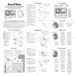
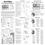
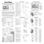
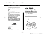
Installing The Sensor
Page 69-70 of User-manual
Mount and Wire the Sensor
D
TOP
EL H
ERE
LEV
left corner of mounting base into mounting
surface (do not tighten yet).
ESP-SMT Smart Modular Control System
C
TOP
LEVEL HERE
A
Drive a mounting screw through hole in upper
A
D
Align mounting base to approximate level
B
INITIAL CONTROLLER
& ZONE SET-UP DIAL
POSITIONS (LIGHT BLUE)
ALARM LIGHT ILLUMINATES
WHEN CONDITIONS PREVENT
IRRIGATION
LARGE BACK-LIT
DOT-MATRIX
DISPLAY
B
position. Drive a second screw into slot in
lower right corner of mounting base (do not
tighten yet).
Quick Installation & Setup Guide
Initial Controller Setup
Controls, Switches and Indicators
G
Assure mounting base is level, then tighten
C
SCREEN TITLE
ACCESS HERE TO
CLEAN RAIN SENSOR
F
the screw in slot.
SET CURRENT
DATE AND TIME
AUTO
SET DATE
& TIME
OFF
10:16 AM
BACK
To secure base, assure that all 3 additional
D
RESTORE
SETTINGS
screws are tightened to the mounting surface.
E
Unscrew the captured screw to remove the
E
SCREEN TEXT
24 Mar 2009
CONFIGURE
CONTROLLER
MANUAL
WATERING
NEXT
FUNCTION LABELS
FOR SET-UP &
NAVIGATION
INPUT ZONE
INFORMATION
SYSTEM
REVIEW
FINE-TUNE
WATERING
SPECIAL
FEATURES
ENGLISH
ESPAÑOL
wiring compartment cover and expose the
wiring terminals.
NAVIGATION
BUTTONS WITH
ACCELERATOR
H
Strip the wire insulation 3/8” and insert bare,
F
copper-leads into the tool-less connectors
(polarity is not important).
ENGLISH/SPANISH
BUTTON FOR
EASY SWITCHING
OF DISPLAY
LANGUAGE
L
If the controller is powered, the green LED
G
located adjacent to the terminal strip will
illuminate once communication is
established.
The ESP-SMT Smart Modular controller panel is designed to upgrade
previously installed ESP-Modular controllers (ESP-SMT RETRO).
K
Route the wire through the two openings in
H
the wiring compartment cover, then tighten
the captured screw to secure cover.
Welcome To The Rain Bird ESP-SMT Smart Control System
the 2 mounting bracket arms for strain relief.
Rotate dial to SET DATE & TIME
A
Set Date & Time
position.
The Rain Bird ESP-SMT “Smart” Modular Control System has many advanced features based on scientific agronomic principles.
It is designed for you to easily and conveniently keep your client’s landscape healthy and vibrant by optimizing the irrigation
schedule to match the plant water needs associated with changing weather conditions.
Slide the sensor housing assembly over the
J
You are about to install a controller that many of our field test participants commented that this control system is what they
need to irrigate correctly and save water. They also stated that this controller is much easier and faster to program than any
other controller they have used.
Adjust each of the mounting arms to assure
K
that the sensor is secured in a level position.
To leverage the water savings potential of the ESP-SMT control system, it is important that you become familiar with both the
basic as well as advanced capabilities of the controller. If you would like to better understand Plant-Soil-Water relationship
principles or learn more about how to maximize the water savings and your profits with the ESP-SMT Smart Control System, we
offer a free, comprehensive on-line tutorial program. To learn more, visit the Rain Bird website... www.rainbird.com
J
Route the wires through the 3 holes located in
I
Page 7-8 of User-manual
top of the mounting arm and secure with the
provided thumb screw.
Set current Month.
B
Set current Day of Month
C
Set current Year.
D
Set current Hour
E
I
Slip the sensor debris cover onto top of sensor.
L
B
C
SET CURRENT
DATE AND TIME
E
24 Mar 2009
D
F
02:54 PM
RETR.
SIG.
(assure AM or PM is correct).
Set current Minutes.
6
Thank you for doing your part to conserve our most precious natural resource... WATER!
Box Contents and Required Tools
Installing The Controller
Configure Controller
Page 57-68 of User-manual
Box Contents
Page 9-18 of User-manual
A
B
ALARM
Rotate dial to CONFIGURE
A
AUTO
SET DATE
& TIME
OFF
ESP-SMT Controller (or retro-fit panel only)
A
* Controller Mounting Hardware
B
* Controller Mounting Template
C
ESP-SMT Installation & Operation Guide
D
ESP-SMT Site Profile Chart
E
ESP-SMT Installation & Quick Setup Poster
F
SMT Weather Sensor
G
Weather Sensor Debris Screen
H
Weather Sensor Mounting Bracket
I
Mounting Bracket Hardware
J
Sensor Wire - 25 feet of 20-2 UV rated wire
K
(not rated for direct burial)
* Controller models only
A
RESTORE
SETTINGS
ALARM
Mount the Controller
CONFIGURE
CONTROLLER
MANUAL
WATERING
AUTO
SYSTEM
REVIEW
FINE-TUNE
WATERING
SPECIAL
FEATURES
Remove the controller door from cabinet
A
ENGLISH
ESPAÑOL
ESP-SMT
SMART MODULAR CONTROLLER
CONFIGURE
CONTROLLER
MANUAL
WATERING
RESTORE
SETTINGS
hinges.
FINE-TUNE
WATERING
SPECIAL
FEATURES
shaped finger hold on the top right side of the
cabinet.
Disconnect cable from back of panel.
C
#8 SCREW
LEVEL LINE
Remove controller panel from cabinet hinge
D
ESP-SMT SMART MODULAR CONTROLLER
MOUNTING TEMPLATE
pins.
Allow 11" clearance to the left side of the
template to allow the door to open fully.
This device complies with Part 15 of the FCC Rules.
(1) This device may not cause harmful interference and
(2) This device must accept any interference received,
including interference that may cause undesired operation.
DAYS (if necessary)
Installation & Operation Guide
#8 SCREW
#8 SCREW
#8 SCREW
P/N: 637654-01
G
Installation Tools (not shown)
Phillips slot-head screwdriver
Drive a screw at eye level into the mounting
E
wall surface. Leave approximately a 3/8" gap
from wall.
Slide controller keyhole slot (located on back
F
Enter 1st Watering
E
Review Entered Info
H
SITE ZIP CODE
SET ALLOWED WATER TIME
1st Watering Time
06:00 AM To 06:00 PM
2nd Watering Time OFF
ALLOWED WATERING
By Days of the Week
We
Fr
Mo
05:00 AM To 09:00 AM
06:00 PM To 11:45 PM
Grow-in: Daily
09:00 AM To 04:00 PM
CHANGE
ACCEPT
thru the holes located at bottom of controller.
H
Wire stripper
Torpedo level
SMX SENSOR
WARNING
ACCESSORY
RESET
IF DISPLAY IS SCRAMBLED
OR BLANK, PUSH THE
RESET BUTTON
of the cabinet) onto the screw.
Secure controller by driving 3 screws into wall
G
Marking pencil for template
Watering Time
B
Cet appariel Numérique de la classe B respecte toutes les
exigences du Règlement sur le matériel brouilleur du Canada.
RI SK OF FI RE , EX PL OS IO N AN D EL EC TR IC AL SH OC K.
TH IS CO NT RO LL ER US ES A NO N- RE PL AC EA BL E LI TH IU M
BA TT ER Y. DI SP OS E OF AL L EL EC TR ON IC PR OD UC TS IN
AC CO RD AN CE WI TH LO CA L LA WS AN D FE DE RA L RE GU LA TI ON S.
Enter GROW-IN
G
SET ALLOWED WATER TIME
1st Watering Time
05:00 AM To 09:00 AM
2nd Watering Time
ON
08:00 PM To 12:00 AM
Grow-in Watering Time
09:00 AM To 04:00 PM
BACK
NEXT
Canadian Interference Causing Equipment Regulations.
ESP-SMT Smart Modular Control System
Time
BLOCK WATERING ON
SPECIFIC DAY OF WEEK
None
Monday
Tuesday
Wednesday
Thursday
Friday
Saturday
Sunday
Sat & Sun
SELECT
BACK
LAWN SPRINKLER CONTROL
-DOMESTICINPUT: 120 VAC, 0.3 AMPS, 60Hz
OUTPUT: 25.5 VAC, 1.0 AMPS, 60Hz
This class B digital apparatus meets all requirements of the
D
E
F
SET ALLOWED WATER TIME
1st Watering Time
05:00 AM To 09:00 AM
2nd Watering Time
ON
08:00 PM To 11:45 PM
Grow-in Watering Time
08:00 AM To 05:00 PM
BACK
NEXT
Select BLOCK WATER
D
C
Operation is subjected to the following two conditions:
ALLOWED WATER DAYS
No Restrictions
By Days of the Week
Even Days: 2,4,6,… 30
Odd Days: 1,3,5,…no31
Cyclical: Every x Days
SELECT
BACK
ENGLISH
ESPAÑOL
ESP-SMT
Open the face panel by grasping the crescent
B
C
Enter 2nd Watering
F
INPUT ZONE
INFORMATION
SYSTEM
REVIEW
SMART MODULAR CONTROLLER
B
Select ALLOWED
C
WATER DAYS
CONTROLLER position.
SET DATE
& TIME
OFF
INPUT ZONE
INFORMATION
Enter SITE ZIP CODE
D
E
F
Enter Site Zip Code
92010
I
J
BACK
Time
Grow In Watering Time
08:00 AM To 05:00 PM
BACK
NEXT
NEXT
(Change or Accept)
Drill bit & hammer drill
Ladder (if mounting sensor more
than 6' above grade)
K
Locate The Sensor
Do’s
Don't’s
Install sensor in a location that receives afternoon sun
in order to measure the daily high temperature (South
or West exposure is ideal).
Do NOT install sensor in a location where spray from the
sprinkler will collect in the sensor.
Mount weather sensor at least six feet above grade.
Do NOT install the sensor where it will be located in the
shade during the hottest part of the day.
Assure that sensor is free from obstructions to allow for
collection and accurate measurement of rainfall.
Do NOT install the sensor where rainfall will be blocked
from entering the sensor funnel.
G
Input Zone Information
Connect Field Wiring
Page 19-34 of User-manual
Connect each valves separate power wire to
H
the corresponding station (zone) terminal.
Rotate dial to INPUT
A
Connect a common wire to one of the leads on
I
each valve.
Connect the other end of the common wire to
J
Select SPRINKLER TYPE
E
ZONE INFORMATION
position
J
the terminal location labeled COM.
!
NOTE: All 120V Power and Field Wiring
(Valves & Pumps) is performed in the
same manner as any other traditional
time-based controller. For Pump, Master
Valve and Control Valve Wiring Details,
See User Manual – pages 61 to 62.
PLANT DENSITY
Sprays
Rotors
Rotary Noz
Bubblers
Drip
Custom Values
- OR Time-Based
SELECT
BACK
Mixed Plants
Dense
Medium
Sparse
Select SOIL TYPE
F
I
SOIL TYPE
This device complies with Part 15 of the FCC Rules.
LAWN SPRINKLER CONTROL
-DOMESTICINPUT: 120 VAC, 0.3 AMPS, 60Hz
OUTPUT: 25.5 VAC, 1.0 AMPS, 60Hz
(1) This device may not cause harmful interference and
Run provided wire or 18-2 AWG direct burial,
K
(2) This device must accept any interference received,
including interference that may cause undesired operation.
Select ZONE SETUP
B
This class B digital apparatus meets all requirements of the
WIZARD method
Canadian Interference Causing Equipment Regulations.
UV rated wire from sensor to controller (200 ft.
max).
Cet appariel Numérique de la classe B respecte toutes les
exigences du Règlement sur le matériel brouilleur du Canada.
K
SMX SENSOR
WARNING
RISK OF FIRE, EXPLOSION AND ELECTRICAL SHOCK.
THIS CONTROLLER USES A NON-REPLACEABLE LITHIUM
BATTERY. DISPOSE OF ALL ELECTRONIC PRODUCTS IN
ACCORDANCE WITH LOCAL LAWS AND FEDERAL REGULATIONS.
ACCESSORY
L
WIRES FROM
SMT SENSOR
RESET
ZONE SETUP
Zone Setup Wizard
Advanced User Entry
Copy Zone to Zone
IF DISPLAY IS SCRAMBLED
OR BLANK, PUSH THE
SELECT
RESET BUTTON
Route the two wires through the provided
M
channel and out through one of the
knockouts, located in the bottom of the
controller cabinet.
M
Select ZONE #
C
SELECT ZONE
BACK
SENSOR WIRE
(MAX 200 FT.)
P/N: 637728-01
SELECT
BACK
Zone 2
Select SHADE
K
FACTOR (all plants)
SHADE FACTOR
Sand
Loamy Sand
Sandy Loam
Loam
Clay Loam Silty Clay
Clay
Operation is subjected to the following two conditions:
ESP-SMT
CONTROLLER
Zone 1
H
Connect Sensor Wire to Controller
leads into connector located on back of front
panel (polarity not important).
(non grass)
SPRINKLER TYPE Zone 1
BACK
Strip wire insulation approx 3/8" and insert
L
Enter PLANT DENSITY
J
Zone 3
OFF NEXT
Help
SELECT
Select DEGREE SLOPE
G
SLOPE IN DEG.
Zone 1
0-2°
3-4°
5-7°
8°-up
Soil Type
Sandy Loam
Cycle/Soak Automatic
Max Cycle Time 15 Min
Min Soak Time
39 Min
SELECT
BACK
Select PLANT TYPE
H
PLANT TYPE
Zone 1
Grass Lawn
Annuals
Ground Cover
Shrubs
Desert Plants
Trees
Mixed Planting
- OR Custom Plant Factors
SELECT
BACK
BACK
Full Sun
25% Shade
50% Shade
75% Shade
Full Shade
Zone 1
SELECT
Enter PLANT
L
MATURITY (all plants)
PLANT MATURITY Zone 2
Established
- OR Newly Planted
Grow-in Period
BACK
SELECT
Enter NEWLY PLANTED
M
schedule (if needed)
NEWLY PLANTED
Zone 2
Water Every Calendar
Day For Next
14 Days
Cycles per Day
6
Minutes Per Cycle
8
09:00 AM to 04:00 PM
NEXT
BACK
Remote Programming of Controller Panel
Insert 9-volt battery into the back of front
N
panel to program the controller without AC
power to the unit. Once completed, remove 9volt battery from unit.
!
This device complies with Part 15 of the FCC Rules.
Operation is subjected to the following two conditions:
(1) This device may not cause harmful interference and
(2) This device must accept any interference received,
including interference that may cause undesired operation.
LAWN SPRINKLER CONTROL
-DOMESTICINPUT: 120 VAC, 0.3 AMPS, 60Hz
OUTPUT: 25.5 VAC, 1.0 AMPS, 60Hz
Enter PLANT WATER
I
Review Entered Info
N
PLANT WATER
Zone 1
NEED
Mixed Plants
High
Medium
Low
SELECT
BACK
REVIEW
Zone 2
ON
Rotor
0.4 in/hr
Sandy Loam
Slope
8° - up
Shrubs
Medium
Sparse
75% Shade
Plants Established
CHANGE
ACCEPT
NEED (non grass)
(Change or Accept)
This class B digital apparatus meets all requirements of the
SELECT ZONE
Canadian Interference Causing Equipment Regulations.
Cet appariel Numérique de la classe B respecte toutes les
exigences du Règlement sur le matériel brouilleur du Canada.
SMX SENSOR
NOTE: All of the programmed information will be saved in non-volatile
memory so you can pre-program the
controller in advance of AC power
availability.
ENABLE zone
D
N
WARNING
RI SK OF FI RE , EX PL OS IO N AN D EL EC TR IC AL SH OC K.
TH IS CO NT RO LL ER US ES A NO N- RE PL AC EA BL E LI TH IU M
BA TT ER Y. DI SP OS E OF AL L EL EC TR ON IC PR OD UC TS IN
AC CO RD AN CE WI TH LO CA L LA WS AN D FE DE RA L RE GU LA TI ON S.
ACCESSORY
RESET
Zone 3
ENABLED
OFF ENABLE NEXT
BACK
IF DISPLAY IS SCRAMBLED
OR BLANK, PUSH THE
RESET BUTTON
Repeat process for all
desired Zones.