1
User Manual
SP-12000M-CXP4
SP-12000C-CXP4
12M Digital Progressive Scan
Monochrome and Color Camera
Document Version: 1.0
SP-12000-CXP4_Ver.1.0_Dec2015
Thank you for purchasing this product.
Be sure to read this manual before use.
This manual includes important safety precautions and instructions on
how to operate the unit. Be sure to read this manual to ensure proper
operation, and store it safely for future use.
© 2015 JAI
SP-12000M-CXP4 / SP-12000C-CXP4
Contents
Notice.............................................................................3
Warranty........................................................................3
Certifications..................................................................3
Warning.........................................................................3
Usage Precautions........................................................6
Features.........................................................................7
Parts Identification.........................................................8
Video Send Mode........................................................39
Video Send Mode....................................................39
To switch the video send mode...........................39
Multi ROI function................................................39
Sequence Trigger function..................................40
ALC (Automatic Level Control) Function......................43
To use the ALC function.......................................43
Automatic gain level control................................43
Detailed Settings for Gain Auto (Automatic Gain
Level Control)..........................................................43
PIV Function................................................................44
HDR (High Dynamic Range) Mode
(SP-12000M-CXP4 only).............................................45
Video Process Bypass Mode.......................................47
Available bit-depth options..................................47
Differences in camera operation.............................47
When Video Process Bypass mode is
disabled..........................................................47
When Video Process Bypass mode is
enabled...........................................................47
Preparation........................................................... 13
Preparation Process....................................................13
Step 1: Installing the Software (first time only).............13
Enabling the CXP frame grabber board..............14
Step 2: Connecting Devices.........................................14
Step 3: Verifying the Camera’s Connection Status......16
Step 4: Configuring Initial Settings for the Camera......16
Connecting to the Camera to Control Tool..............16
Configuring the optimal link configuration...........16
Configuring the Output Format................................17
Configuring Exposure and External Trigger
Settings....................................................................18
Control via External Triggers........................................19
When Controlling the Exposure Time Using
Specified Exposure Times.......................................19
When Controlling the Exposure Time Using the
Pulse Width of the Trigger Input Signal...................19
Control Without External Triggers................................20
When Controlling the Exposure
Time Using Specified Exposure Times....................20
When not Controlling the Exposure Time................21
Step 5: Adjusting the Image Quality............................21
Adjusting the Gain...................................................21
Manual adjustment..............................................21
Adjusting the White Balance (SP-12000C-CXP4
only).........................................................................22
Manual white balance adjustment.......................22
Automatic white balance adjustment..................22
Adjusting the Black Level........................................22
Step 6: Configuring Various Other Settings.................22
Step 7: Saving the Settings..........................................23
To save user settings...........................................23
To load user settings............................................24
Basic Function Matrix..................................................24
Settings List.......................................................... 48
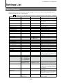
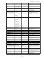
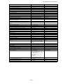
Feature Properties.......................................................48
Settings........................................................................53
Miscellaneous....................................................... 55
Updates.......................................................................55
Troubleshooting...........................................................55
Specifications...............................................................56
Frame Rate Reference................................................58
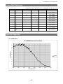
Spectral Response......................................................58
Dimensions..................................................................59
User’s Record..............................................................60
Index...................................................................... 61
Main Functions..................................................... 25
GPIO (Digital Input/Output Settings)............................25
Valid Input/Output Combinations.............................25
Acquisition Control (Image Acquisition Controls).........26
Changing the Frame Rate.......................................26
Maximum Frame Rate..............................................26
Calculation of frame rate.....................................26
Exposure Mode............................................................27
Trigger Control.............................................................27
Shortest Repetition Period for Triggers....................28
Gain Control.................................................................35
LUT (Lookup Table).....................................................36
To use the LUT function.......................................36
LUT values...........................................................37
Gamma Function.........................................................37
To use the gamma function.................................37
ROI (Regional Scanning Function)..............................38
ROI Settings.............................................................38
—2—
SP-12000M-CXP4 / SP-12000C-CXP4
Notice
The material contained in this manual consists of information that is proprietary to JAI Ltd., Japan and may
only be used by the purchasers of the product. JAI Ltd., Japan makes no warranty for the use of its product
and assumes no responsibility for any errors which may appear or for damages resulting from the use of the
information contained herein. JAI Ltd., Japan reserves the right to make changes without notice.
Company and product names mentioned in this manual are trademarks or registered trademarks of their
respective owners.
Warranty
For information about the warranty, please contact your factory representative.
Certifications
CE compliance
As defined by the Directive 2004/108/EC of the European Parliament and of the Council, EMC
(Electromagnetic compatibility), JAI Ltd., Japan declares that SP-12000M-CXP4 and SP-12000C-CXP4 comply
with the following provisions applying to its standards.
EN 61000-6-3 (Generic emission standard part 1)
EN 61000-6-2 (Generic immunity standard part 1)
FCC
This equipment has been tested and found to comply with the limits for a Class B digital device, pursuant
to Part 15 of the FCC Rules. These limits are designed to provide reasonable protection against harmful
interference in a residential installation. This equipment generates, uses and can radiate radio frequency
energy and, if not installed and used in accordance with the instructions, may cause harmful interference
to radio communications. However, there is no guarantee that interference will not occur in a particular
installation. If this equipment does cause harmful interference to radio or television reception, which can be
determined by turning the equipment off and on, the user is encouraged to try to correct the interference by
one or more of the following measures:
•Reorient or relocate the receiving antenna.
•Increase the separation between the equipment and receiver.
•Connect the equipment into an outlet on a circuit different from that to which the receiver is connected.
•Consult the dealer or an experienced radio/TV technician for help.
Warning
Changes or modifications to this unit not expressly approved by the party responsible for
FCC compliance could void the user’
s authority to operate the equipment.
—3—
SP-12000M-CXP4 / SP-12000C-CXP4
Supplement
The following statement is related to the regulation on “ Measures for the Administration
of the control of Pollution by Electronic Information Products “ , known as “ China RoHS “.
The table shows contained Hazardous Substances in this camera.
mark shows that the environment-friendly use period of contained Hazardous
Substances is 15 years.
嶷勣廣吭並㍻
嗤蕎嗤墾麗嵎賜圷殆兆各式根楚燕
功象嶄鯖繁酎慌才忽佚連恢匍何〆窮徨佚連恢瞳麟半陣崙砿尖一隈〇云恢瞳ゞ 嗤蕎嗤
墾麗嵎賜圷殆兆各式根楚燕 〃泌和
桟隠聞喘豚㍉
窮徨佚連恢瞳嶄根嗤議嗤蕎嗤墾麗嵎賜圷殆壓屎械聞喘議訳周和音氏窟伏翌
亶賜融延、窮徨佚連恢瞳喘薩聞喘乎窮徨佚連恢瞳音氏斤桟廠夛撹冢嶷麟半
賜斤児繁附、夏恢夛撹冢嶷鱒墾議豚㍉。
方忖仝15々葎豚㍉15定。
—4—
SP-12000M-CXP4 / SP-12000C-CXP4
Supplement
The following statement is related to the regulation on “ Measures for the Administration
of the control of Pollution by Electronic Information Products “ , known as “ China RoHS “.
The table shows contained Hazardous Substances in this camera.
mark shows that the environment-friendly use period of contained Hazardous
Substances is 15 years.
嶷勣廣吭並㍻
嗤蕎嗤墾麗嵎賜圷殆兆各式根楚燕
功象嶄鯖繁酎慌才忽佚連恢匍何〆窮徨佚連恢瞳麟半陣崙砿尖一隈〇云恢瞳ゞ 嗤蕎嗤
墾麗嵎賜圷殆兆各式根楚燕 〃泌和
桟隠聞喘豚㍉
窮徨佚連恢瞳嶄根嗤議嗤蕎嗤墾麗嵎賜圷殆壓屎械聞喘議訳周和音氏窟伏翌
亶賜融延、窮徨佚連恢瞳喘薩聞喘乎窮徨佚連恢瞳音氏斤桟廠夛撹冢嶷麟半
賜斤児繁附、夏恢夛撹冢嶷鱒墾議豚㍉。
方忖仝15々葎豚㍉15定。
—5—
SP-12000M-CXP4 / SP-12000C-CXP4
Usage Precautions
Notes on cable configurations
The presence of lighting equipment and television receivers nearby may result in video and audio
noise. In such cases, change the cable configurations or placement.
Notes on attaching the lens
Avoiding dust particles
When attaching the lens to the camera, stray dust and other particles may adhere to the sensor
surface and rear surface of the lens. Be careful of the following when attaching the lens.
•Work in a clean environment.
•Do not remove the caps from the camera and lens until immediately before you attach the lens.
•To prevent dust from adhering to surfaces, point the camera and lens downward and do not allow the
lens surface to come into contact with your hands or other objects.
•Always use a blower brush to remove any dust that adheres.
Never use your hands or cloth, blow with your mouth, or use other methods to remove dust.
Phenomena specific to CMOS image sensors
The following phenomena are known to occur on cameras equipped with CMOS image sensors. These
do not indicate malfunctions.
• Aliasing
When shooting straight lines, stripes, and similar patterns, vertical aliasing (zigzag distortion) may
appear on the monitor.
• Blemishes
Due to the sensor element (pixel) array inside the CMOS image sensor, blemishes may occur when
strong light enters. However, this does not affect actual operation.
• Fixed pattern noise
When shooting dark objects in high-temperature conditions, fixed pattern noise may occur
throughout the entire video monitor screen.
• Defective pixels
Defective pixels (white and black pixels) of the CMOS image sensor are minimized at the factory
according to shipping standards. However, as this phenomenon can be affected by the ambient
temperature, camera settings (e.g., high sensitivity and long exposure), and other factors, be sure to
operate within the camera’s specified operating environment.
Notes on exportation
When exporting this product, please follow the export regulations of your country or region.
—6—
SP-12000M-CXP4 / SP-12000C-CXP4
Features
The SP-12000M-CXP4/SP-12000C-CXP4 is an industrial progressive scan camera equipped with an
APS-C format global shutter CMOS image sensor with 12.58 effective megapixels (4096 × 3072). The
unit is equipped with a CoaXPress Ver. 1.0 interface.
The SP-12000M-CXP4 produces monochrome output while the SP-12000C-CXP4 produces Bayer output.
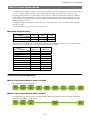
Coaxial cable interface supporting CoaXPress Ver. 1.0
•High-speed transfer at up to 25 Gbps of uncompressed data, the ideal format for image processing.
•Maximum cable lengths for the recommended cables are as follows.
3.125G
100 m
55 m
Belden 1694A
Belden 1855A
6.25G
40 m
25 m
Note
The frame grabber board that you use must support CoaXPress. Power can also be supplied via the 12-pin
connector using an optional +12 to +24V DC power supply. PoCXP is also supported.
Output formats
You can choose from 8-bit and 10-bit output for both monochrome and Bayer in normal mode.
12-bit output is possible in Video Process Bypass mode (see page 47).
High frame rate
The SP-12000M-CXP4 and SP-12000C-CXP4 are both capable of frame rates of up to 189 fps (8-bit
format) for full 12-megapixel output. Even faster frame rates can be achieved when a smaller ROI
(region of interest) is specified.
Automatic level control (ALC) function
Combine the automatic gain control and automatic exposure control functions to allow handling of
changes in various brightnesses.
Variety of pre-process functions
•LUT (lookup table)
For programmable control over gamma and contrast.
•Gamma correction
The gamma can be set to one of nine settings from 0.45 to 1.0.
•Bayer white balance (SP-12000C-CXP4 only)
White balance can be automatically adjusted continuously. It can also be adjusted manually using R,
G, and B gain.
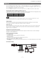
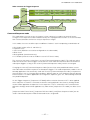
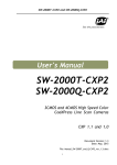
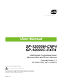
Connection example:
Camera
External trigger
AC adapter
CoaXPress frame
grabber board
—7—
Computer
SP-12000M-CXP4 / SP-12000C-CXP4
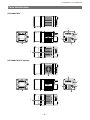
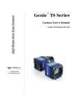
Parts Identification
SP-12000-CXP4
③
④
⑦
⑤
①
⑥
⑧
SP-12000-CXP4-XT (option)
②
③
④
⑦
①
⑤
⑥
⑧
—8—
SP-12000M-CXP4 / SP-12000C-CXP4
1 Lens mount (F-mount)
Mount an F-mount lens, microscope adapter, etc. here.
2 Ventilation holes (SP-12000-CXP4-XT (option) only)
3 CXP (CoaXPress) connectors 1 to 4 (DIN)
Connect the coaxial cables for digital video output here. (Equivalent to Amphenol Connex
ACX1785-ND. PoCXP is also supported.)
4 LINK LEDs 1 to 4
Indicates the CXP connection status.
LED status and camera status
LED
POWER/TRIG LED
LINK LEDs 1 to 4
Light
Status
Lit green
Off
Lit amber
Blinking amber (rapid)
Blinking amber (slow)
/
Alternating between
green and amber (rapid)
/
Alternating between
green and amber (slow)
/
/
Blinking red,
green, amber (slow)
Lit green
Blinking green
Red pulse (slow)
Lit red
/
Alternating between
red and green (slow)
/
Alternating between
red and amber (slow)
Off
—9—
Power is on.
Power is off.
System starting up.
Detecting link (when PoCXP not in use).
Blinks for 1 second even when detected
immediately.
Waiting for connection between device and host to
be established or for event (trigger, exposure pulse,
etc.) to occur.
Detecting link (when using PoCXP).
Blinks for 1 s even when detected immediately.
Sending connection test packet.
Compliance test mode enabled (equipment only).
Connection between device and host is established,
but there is no data being transmitted.
An error occurred during data transmission (CRC
error, single bit error, etc. detected).
Lights for at least 200 ms before errors are
displayed when multiple errors occur
simultaneously.
Connection between device and host is established,
and data is being transmitted.
No connection.
Does not apply to devices using PoCXP.
PoCXP overcurrent (host side only).
PoCXP has been established, but a connection
error between the device and host has occurred.
A connection error between the device and host has
occurred while PoCXP is not in use.
Power is off.
SP-12000M-CXP4 / SP-12000C-CXP4
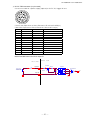
5 DC IN / TRIG connector (12-pin round)
Connect the cable for a power supply (optional) or for DC IN / trigger IN here.
Camera side: Equivalent to Hirose Electronic HR-10A-10R-12PB(72)
Cable side: Equivalent to Hirose Electronic HR10A-10P-12S(73)
Pin No.
1
2
3
4
5
6
7
8
9
10
11
12
IN
IN
OUT
OUT
OUT
IN
Power IN
GND
Name
GND
DC (+12V) IN
GND
NC
Opto INOpto IN+
Opto OUTOpto OUT+
TTL OUT
TTL IN
DC (+12V) IN
GND
Note
DC 12 V to 24 V ±10%
Line 5
Line 2
Line 1
Line 4
Recommended internal circuits for Opto IN
Camera side
BF545C
Opto IN+
User power
+3.3V to +24V
D
180CS
Opto IN-
180CS
S
TLP2366
1
1SS400
User side
G
Attribute
GND
Power IN
GND
3
— 10 —
6
5
4
TC7WG14FK
3
5
IN
SP-12000M-CXP4 / SP-12000C-CXP4
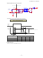
Recommended internal circuits for Opto OUT
User side
Camera side
6
User power
Opto OUT-
1SS400
220BS
270
2SC6033
1
OUT
1
180BS
5
+5V to +24V
OUT
7
TLP109 (TPR,E)
Opto OUT+
4
3
TC7WG14FK
100KBS
220BS
Characteristics of the recommended circuits for Opto OUT
OUTPUT LINE RESPONSE TIME
Camera
Output
Signal
RT
TDF
FT
Output
Line
Voltage
90%
Output LEVEL = User Vcc- (0.8 to 1.1)
10%
TDR
When 270 Ω terminals are used
Time Delay Rise
Rise Time
Time Delay Fall
Fall Time
TDR (μs)
RT (μs)
TDF (μs)
FT (μs)
3.3 V
0.54
1.2
1.5
3.6
User power (Vcc)
5V
12 V
0.54
0.62
1.2
2.0
1.5
2.4
3.4
4.5
6 POWER/TRIG LED
Indicates the power and trigger input status.
— 11 —
24 V
0.68
3.0
2.1
6.8
SP-12000M-CXP4 / SP-12000C-CXP4
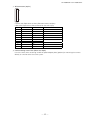
7 AUX connector (10-pin)
8
1
Camera side: Equivalent to Hirose Electronic 3260-10S3(55)
Cable side: Equivalent to Hirose Electronic 350-10P-C(50)
Pin No.
1
2
3
4
5
6
7
8
9
10
Attribute
OUT
OUT
IN
GND
IN
IN
GND
GND
Name
TTL OUT2
TTL OUT3
TTL_IN2
NC
GND
LVDS_IN1+
LVDS_IN1NC
GND
GND
Note
Line 8
Line 9
Line 10
Line 11
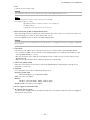
8 Camera locking screw holes (M3, 5 mm depth)
Use these holes when attaching an MP-42 tripod adapter plate (optional) or mounting the camera
directly to a wall or other structural system.
— 12 —
SP-12000M-CXP4 / SP-12000C-CXP4
Preparation
Preparation Process
Step 1
Installing the Software (first time only)
Install the software for configuring and controlling the camera (JAI SDK) on the computer.
Step 2
Connecting Devices
Connect the lens, CXP cable, AC adapter, computer, and other devices.
Step 3
Verifying the Camera’s Connection Status
Verify whether the camera is ready for use via the LEDs at the rear of the camera.
Step 4
Configuring Initial Settings for the Camera
• Configure the output format.
• Configure settings related to the exposure and external trigger.
Step 5
Adjusting the Image Quality
• Adjust the gain and white balance.
• Adjust the exposure (shutter).
Step 6
Configuring Various Other Settings
Configure various other settings as necessary.
Step 7
Saving the Settings
Save the current setting configurations in user memory.
Step 1: Installing the Software (first time only)
When using the camera for the first time, install the software for configuring and controlling the camera
(JAI SDK) on the computer.
When you install JAI SDK, JAI Camera Control Tool will also be installed.
Download the “JAI - Getting Started Guide” and JAI SDK from the JAI website.
1 URL:
http://www.jai.com/en/support/download-jai-software
Refer to the “JAI - Getting Started Guide,” and install JAI SDK on the computer.
2 The
computer will restart when installation is complete.
Note
When the JAI SDK is installed, a camera driver for the GigE interface is also part of the default installation. This
GigE Vision Filter Driver is added to every NIC/port on the host computer. As the driver is also added to the NIC/
port for Internet connection, it may, on some systems, affect Internet access speed. If you think your Internet
speed is affected, configure the following settings to disable the filter driver on that port.
u Open [Control Panel] [Network and Internet] [Connect to a network], and right-click the port used for
Internet connection to open the properties dialog box.
— 13 —
SP-12000M-CXP4 / SP-12000C-CXP4
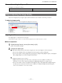
v Clear the [JAI GigE Vision Filter Driver] checkbox, and save.
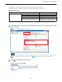
■■Enabling the CXP frame grabber board
1 Start JAI Control Tool.
Click the settings icon at the top right of the window.
2 The
[Settings] window appears.
the + icon for your CXP frame grabber board under [64-bit Factory Transport Layers]
3 Click[Available
64-bit Transport Layers] to display its settings.
4 Set [Enabled] to [True].
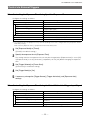
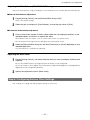
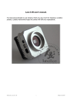
Step 2: Connecting Devices
Connect the lens, CXP cable, AC adapter, and other devices.
Attach the lens in a clean environment to prevent dust from adhering to the unit.
3CXP cables
1Lens
Camera body
4CXP frame
grabber board
2Direct connection
(or MP-42 tripod adapter plate)
6DC IN / trigger IN
connection cable
or
7AC adapter
(power supply)
— 14 —
5Computer
to external trigger
SP-12000M-CXP4 / SP-12000C-CXP4
1 Lens
F-mount lenses can be used.
Caution
The maximum performance of the camera may not be realized depending on the lens.
Note
The following formula can be used to estimate the focal length.
focal length = WD / (1 + W/w)
WD: Working distance (distance between lens and object)
W: Width of object
w: Width of sensor (18.16 mm on this camera)
2 Direct connection (or MP-42 tripod adapter plate)
When mounting the camera directly to a wall or other structural system, use screws that match the
camera locking screw holes on the camera. (M3, 5 mm)
Use the supplied screws to attach the tripod adapter plate.
Caution
For heavy lenses, be sure to support the lens itself. Do not use configurations in which its weight is supported
by the camera.
3 CXP cables
Connect the CXP cables to the CXP connectors on the camera and the frame grabber board.
•The number of cables you can connect varies depending on the number of connectors on your
frame grabber board (1, 2, or 4).
•Be sure to connect each cable to matching connector numbers on the camera and the frame
grabber board.
•Refer to the specifications of the cable for details on its bend radius.
4 CXP frame grabber board
Refer to the instruction manual of the CXP frame grabber board, and configure settings on the
computer as necessary.
5Computer
Use a computer that meets the following requirements.
Operating system (OS):
Microsoft Windows 7/8 32-bit/64-bit edition
CPU: Intel Core i5 or higher
Memory:
Windows 7/8 32-bit edition: DDR3, 4 GB or higher
Windows 7/8 64-bit edition: DDR3, 8 GB or higher
Graphics card: PCI-Express 3.0 or higher
6 DC IN / trigger IN connection cable
7 AC adapter (power supply)
Connect the AC adapter and the round connector of the connection cable to the DC IN / trigger IN
connector on the camera.
— 15 —
SP-12000M-CXP4 / SP-12000C-CXP4
Step 3: Verifying the Camera’s Connection Status
When power is supplied to the camera while the necessary equipment is connected, the power /
trigger LED and LINE LEDs at the rear of the camera light amber, and initialization of the camera starts.
When initialization is complete, the power / trigger LED lights green. The CXP status indicators (LINK 1
to 4) light or blink according to the connection status.
Verify whether power is being supplied to the camera and whether connection has been established
by checking the rear LEDs.
Lit green
For details on how to read the LEDs, see “LED status and camera status” (page 9) in the “Parts
Identification” section.
Note
Initialization of the camera is not complete until connection with the host is established. If the power / trigger LED
does not switch to green within minutes of supplying power, check the CXP cable and other connections. After
initialization is completed once, the power / trigger LED will remain green, even if the host is disconnected.
Step 4: Configuring Initial Settings for the Camera
Start Control Tool, connect the camera to the CXP frame grabber board, and configure initial settings
for the output format, exposure, external trigger, etc.
Connecting to the Camera to Control Tool
Start JAI Control Tool.
1 Cameras
connected to the CXP frame grabber board are detected and displayed in a window. If
they do not appear, right-click inside the window and select [Search for Cameras].
2 Select the camera you want to configure.
3 Check that the settings of the selected camera are displayed.
■■Configuring the optimal link configuration
Select the [Feature Properties] tab, and set [Device Control] [Link Config] to [CXP6_X4] (when using
a 4-cable connection).
Note
• When using a 1-cable or 2-cable connection, select [CXP6_X1] or [CXP6_X2] respectively.
• The [Link Config] setting cannot be stored and will reset to [CXP3_X4] each time the camera is disconnected.
Be sure to manually switch to the optimal setting each time the camera is reconnected.
— 16 —
SP-12000M-CXP4 / SP-12000C-CXP4
Configuring the Output Format
Configure the size, position, and pixel format of the images to be acquired.
The factory default settings are as follows. Change the settings as necessary.
Factory default values
Image Format Control
Item
Width
Height
Offset X (horizontal position)
Offset Y (vertical position)
Pixel Format
Default value
4096 (pixels)
3072 (pixels)
0 (pixels)
0 (pixels)
SP-12000M-CXP4: 8 Bit Monochrome
SP-12000C-CXP4: 8 Bit Bayer GB
You can specify the image acquisition area. For details, see “ROI (Regional Scanning Function)” (page 38).
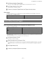
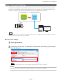
the [Feature Properties] tab, and select the item you want to configure under [Image
1 Select
Format Control].
when a configurable item is selected.
Note
Settings can only be changed when image acquisition on the camera is stopped. If an item is grayed out and
does not appear even when you select it, click
(Stop Acquisition) to stop image acquisition.
2Click
and change the setting value.
Example: When changing [Width]
— 17 —
SP-12000M-CXP4 / SP-12000C-CXP4
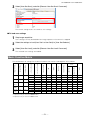
Example: When changing [Pixel Format]
Note
Direct entry of numerical and text values is possible for some setting items.
Configuring Exposure and External Trigger Settings
Configure settings related to exposure control methods and trigger control.
The factory default settings are as follows. Change settings as necessary, according to the intended
purpose or application.
Factory default values
Item
Trigger Selector (trigger operation)
Trigger Mode
Trigger Source (trigger signal source)
Trigger Activation (trigger polarity)
Trigger Overlap
Trigger Option
Exposure Mode
Exposure Time
Exposure Auto*
Default value
Frame Start
Off
Line 4 - TTL In 1
Rising Edge (rising edge of input signal)
Read Out
Off
Timed (control via exposure time)
10486 (µs)
Off
*This item is only enabled when [Exposure Mode] is set to [Timed].
Caution
When [Exposure Mode] is set to [Off], [Trigger Mode] cannot be set to [On]. Other settings may also be restricted
depending on the exposure mode, so be sure to set the exposure mode before configuring the trigger settings.
Configure the settings by expanding [Acquisition Control] and configuring the following items.
Caution
Settings can only be configured when image acquisition on the camera is stopped. If an item is grayed
out and the setting cannot be changed, stop image acquisition beforehand.
— 18 —
SP-12000M-CXP4 / SP-12000C-CXP4
Control via External Triggers
When Controlling the Exposure Time Using Specified Exposure Times
Configure the settings as follows.
Item
Trigger Selector (trigger operation)
Trigger Mode
Trigger Source (trigger signal source)
Trigger Activation (trigger polarity)
Setting value / selectable range
Frame Start
On
Any
Rising Edge (rising edge of input signal), Falling Edge (falling
edge of input signal)
Read Out
Off
Timed (control via exposure time)
15 or 20 to 7999892 (μs) (1 μs/step)*1
Off, Continuous
Trigger Overlap
Trigger Option
Exposure Mode
Exposure Time
Exposure Auto
*1 The maximum value for [Exposure Time] varies depending on the value configured for the [Acquisition Frame
Rate Raw] setting.
Max. value for [Exposure Time] = [Acquisition Frame Rate Raw] value
Set [Exposure Mode] to [Timed].
1 ([Timed]
is the default setting.)
Specify the exposure time in [Exposure Time].
2 The
setting value for the exposure time can only be changed when [Exposure Auto] is set to [Off].
If [Exposure Auto] is set to [Continuous], temporarily set it to [Off] before changing the exposure
time.
Set [Trigger Selector] to [Frame Start].
3 ([Frame
Start] is the default setting.)
4 Set [Trigger Mode] to [On].
If necessary, change the [Trigger Source], [Trigger Activation], and [Exposure Auto]
5 settings.
When Controlling the Exposure Time Using the Pulse Width of the Trigger Input Signal
Configure the settings as follows.
Item
Trigger Selector (trigger operation)
Trigger Mode
Trigger Source (trigger signal source)
Trigger Activation (trigger polarity)
Trigger Overlap
Exposure Mode
Setting value / selectable range
Frame Start
On
Any
Level High (high-level duration), Level Low (low-level
duration)
Read Out
Trigger Width (control via trigger width)
— 19 —
SP-12000M-CXP4 / SP-12000C-CXP4
Set [Exposure Mode] to [Trigger Width] .
1 When
you select [Trigger Width], [Trigger Mode] will automatically be set to [On].
Set [Trigger Selector] to [Frame Start].
2 ([Frame
Start] is the default setting.)
3 If necessary, change the [Trigger Source] and [Trigger Activation] settings.
Other controls
In addition to exposure time, the following can also be controlled by external triggers. Select these
control operations in [Trigger Selector].
[Trigger Selector] setting
Acquisition Start
Acquisition End
Description
Start image acquisition.
Stop image acquisition.
Control Without External Triggers
When Controlling the Exposure Time Using Specified Exposure Times
Configure the settings as follows.
Item
Trigger Selector (trigger operation)
Trigger Mode
Exposure Mode
Exposure Time
Exposure Auto
Setting value / selectable range
Frame Start
Off
Timed (control via exposure time)
15 (8-bit) or 20 (10-bit) to 7999892 (μs) (1 μs/step)*1
Off, Continuous
*1 The maximum value for [Exposure Time] varies depending on the value configured for the [Acquisition Frame
Rate Raw] setting.
Max. value for [Exposure Time] = [Acquisition Frame Rate Raw] value
Set [Exposure Mode] to [Timed].
1 ([Timed]
is the default setting.)
Specify the exposure time in [Exposure Time].
2 The
setting value for the exposure time can only be changed when [Exposure Auto] is set to [Off].
If [Exposure Auto] is set to [Continuous], temporarily set it to [Off] before changing the exposure
time.
3 Set [Trigger Mode] to [Off].
4 If necessary, change the [Exposure Auto] setting.
— 20 —
SP-12000M-CXP4 / SP-12000C-CXP4
When not Controlling the Exposure Time
Configure the settings as follows.
Item
Setting value / selectable range
Exposure Mode
Off
Step 5: Adjusting the Image Quality
Adjust the image quality using the gain and white balance (SP-12000C-CXP4 only) functions.
To adjust the image quality
The display level must be changed from [Beginner] to [Guru].
Adjusting the Gain
The digital gain is used for the master gain.
For details on gain control, see “Gain Control” (page 35) in the “Main Functions” section.
■■Manual adjustment
Expand [Analog Control], and set [Gain Auto] to [Off].
1 ([Off]
is the default setting.)
the digital gain.
2 uConfigure
Expand [Analog Control], and select the gain you want to configure in [Gain Selector].
•For the SP-12000M-CXP4, only [Digital All] (master gain) can be configured.
•For the SP-12000C-CXP4, [Digital All] (master gain), [Digital Red] (digital R gain), and [Digital
Blue] (digital B gain) can be configured individually.
v Configure the gain value in [Gain].
•[Digital All] (master gain) can be set to a value from x1 to x16 (0 dB to +24 dB). The
resolution is set in x0.01 steps (0.05 dB to 0.08 dB depending on the setting value).
•For the SP-12000C-CXP4, the [Digital Red] (digital R gain) and [Digital Blue] (digital B gain)
can be set to a value from x0.45 to x5.62 (–7 dB to +15 dB) the [Digital All] (master gain)
value. The resolution is set in x0.01 steps.
— 21 —
SP-12000M-CXP4 / SP-12000C-CXP4
Adjusting the White Balance (SP-12000C-CXP4 only)
Adjust the white balance using R and B gain. The white balance can also be adjusted automatically.
■■Manual white balance adjustment
Expand [Analog Control], and set [Balance White Auto] to [Off].
1 ([Off]
is the default setting.)
2 Select the gain to configure in [Gain Selector], and set the gain value in [Gain].
■■Automatic white balance adjustment
a white sheet of paper or similar object under the same lighting conditions as the
1 Place
intended subject, and zoom in to capture the white.
White objects near the subject, such as a white cloth or wall, can also be used.
Be sure to prevent the high-intensity spot lights from entering the screen.
Select the [Balance White Auto] tab, and click [Continuous] or [Once] depending on your
2 intended
application.
The white balance is automatically adjusted.
Adjusting the Black Level
[Analog Control], and select the black level you want to configure in [Black Level
1 Expand
Selector].
For the SP-12000M-CXP4, only [Digital All] (master black) can be configured.
For the SP-12000C-CXP4, [Digital All] (master black), [Digital Red] (digital R), and [Digital Blue]
(digital B) can be configured individually.
2 Specify the adjustment value in [Black Level].
Step 6: Configuring Various Other Settings
See “Settings List” (page 48) and configure settings as necessary.
— 22 —
SP-12000M-CXP4 / SP-12000C-CXP4
Step 7: Saving the Settings
Setting values configured in Control Tool are maintained in the camera’s temporary memory until the
camera is turned off. By saving current setting values to user memory, you can load and recall them
whenever necessary. You can save up to three sets of user settings on the camera.
User memory
Temporary memory
User Set1
User Set2
User Set3
Save
Current
setting
values
Control Tool
Note
The setting values are not saved to the computer (Control Tool). The setting values will be stored in the camera’s
temporary memory until the camera is turned off.
■■To save user settings
1 Stop image acquisition.
[User Set Control], and select the save destination ([User Set1] to [User Set3]) in
2 Expand
[User Set Selector].
Note
The factory default setting values are maintained in [Default] and cannot be overwritten.
Caution
Settings can only be saved when image acquisition on the camera is stopped.
— 23 —
SP-12000M-CXP4 / SP-12000C-CXP4
3 Select [User Set Save], and click [Execute ‘User Set Save’ Command].
The current setting values are saved as user settings.
■■To load user settings
Stop image acquisition.
1 User
settings can only be loaded when image capture on the camera is stopped.
2 Select the settings to load (User Set1 to User Set3) in [User Set Selector].
Select [User Set Load], and click [Execute ‘User Set Load’ Command].
3 The
selected user settings are loaded.
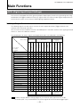
Basic Function Matrix
The combinations of settings for the basic functions that can be used together are as follows.
Exposure Mode
Trigger Mode
Trigger Option
Binning Vertical*1
Binning Horizontal*1
Exposure Time
ROI
AWB*2
Gain Auto
Exposure Auto
Multi ROI
Sequence ROI
HDR*1
Video Send
Mode
Off
Off
Off
×1 (Off)
×1 (Off)
×
×
×
×
Timed
Off
Timed
(EPS)
On
Trigger
Width
On
Timed
(PIV)
On
Off
Off
Off
PIV
×2
×2
×
×
×
×
×
×1 (Off)
×1 (Off)
×
×
×2
×2
×
×
×1 (Off)
×1 (Off)
×2
×2
×
×1 (Off)
×1 (Off)
×
×
×
×
×2
×2
×
×
×
×
×
×1 (Off)
×1 (Off)
×
×
×
×2
×2
×
×
×
×
×
×
×
×
*1 Operates only on the SP-12000M-CXP4
*2 Operates only on the SP-12000C-CXP4
— 24 —
SP-12000M-CXP4 / SP-12000C-CXP4
Main Functions
GPIO (Digital Input/Output Settings)
The camera is equipped with GPIO (general-purpose input/output) functions for generating and using
combinations of triggers and other necessary signals within the camera and of signals output from the
camera to the system such as those used for lighting equipment control.
Valid Input/Output Combinations
The following signals can be used as sources for each output destination (Trigger Selector, Line
Selector, Pulse Generator Selector).
You can also connect two different sources to NAND paths in the GPIO and reuse the signal generated
there as a source for a different selector.
The combinations of source signals and output destinations are indicated in the following.
Selector
(Cross point
switch output)
Output destination
Trigger Selector
Pulse
Generator
Selector
Line Selector
Acquisition Start
Acquisition End
Frame Start
Line 1
Line 2
Line 8
Line 9
NAND 0
NAND 1
Pulse Generator 0
Pulse Generator 1
Pulse Generator 2
Pulse Generator 3
LOW
HIGH
Line 4 (TTL Input)
Line 5 (Opto Input)
Line7 (Trigger packet )
Line 10 (TTL Input2)
Line 11 (LVDS Input)
User Output 0
User Output 1
User Output 2
User Output 3
Software
×
×
×
×
×
×
×
×
×
×
Pulse Generator 0
×
Pulse Generator 1
×
Pulse Generator 2
×
Pulse Generator 3
×
NAND 0 Out
×
NAND 1 Out
Source signal
(Cross point
switch input)
Signals to use as output
×
Exposure Active
Acquisition Active
Acquisition Trigger Wait
Frame Trigger Wait
Frame Active
FVAL
LVAL
×
×
×
×
Trigger Source
Line Source
Pulse
Generator
Clear Source
Use
: Under the factory default settings (page 18), the external input signal from the 12-pin
connector (OPT 1 In) is connected as the source signal for the Frame Start trigger signal.
— 25 —
SP-12000M-CXP4 / SP-12000C-CXP4
Acquisition Control (Image Acquisition Controls)
Perform operations and configure settings related to image acquisition in [Acquisition Control].
The following acquisition modes are available on the camera.
Acquisition Mode
Single Frame
Multi Frame
Continuous
Description
Acquire a single frame when the [Acquisition Start] command is executed.
Acquire the number of frames specified in [Acquisition Frame Count] when the
[Acquisition Start] command is executed. When the PIV function is enabled, the
number of frames can be set to an even value.
Acquire images continuously until the [Acquisition Stop] command is executed.
Changing the Frame Rate
When [Trigger Mode] is disabled, you can change the frame rate in [Acquisition Frame Rate].
Note
• The shortest frame period varies depending on the ROI, pixel format, and binning mode selected. The longest
frame period is 0.125 Hz (8 sec.).
• When [Trigger Mode] is enabled, the [Acquisition Frame Rate] setting is disabled.
Maximum Frame Rate
The maximum frame rate is as follows depending on the sensor’s scanning range and the CXP
bandwidth.
■■Calculation of frame rate
A = { (width_c / 16) × (CXP_BIT / 8) +9 } × (4 / CXP_LANE)
B = Roundup { (2 × A) × (1 / CXP_CLOCK) × (600000000 / SENSOR_BIT) – 1,0 }
C = B=< [H_BLK_Min] => [H_BLK_Min]
B> [H_BLK_Min] => B
Line Time = (C + 1) × (1/600000000) × [Sensor BIT]
FR = 1/ { Line time × ([FOT] + [Height_c] /2) }
[Width_c]
[Height_c]
[H_BLK_Min] [CXP_CLOCK] [CXP_BIT] [CXP_LANE]
[Sensor Digitize]
[FOT]
Binning Horizontal = 1
:width_c = width (128 to 4096)
Binning Horizontal = 2 :width_c = width (128 ~ 2048)/2
Binning Vertical = 1
:Height_c =Height (16 to 3072)
Binning Vertical = 2 :Height_c = Height (16 to 1536)/2
Sensor Digitize: 10bit:128,12bit:244
Link config : 6G:156250000 , 3G:78125000
Digitization Resolution: 8bit:8,10bit:10
Lane: 1Lane:1 ,2Lane:2 ,4Lane:4
Sensor Digitization Resolution: 10bit:10 ,12bit:12
Sensor Digitize: 10bit:14,12bit:9
Configurable ranges
Width*2
Binning Off 1
Binning On 2
Monochrome
128 to 4096
128 to 2048
Height*1
Color
—
*1 Refer to the “Height” values in the “Configurable ranges” table above.
• Be careful of the maximum value during [Binning Horizontal].
— 26 —
Monochrome
16 to 3072
16 to 1536
Color
—
SP-12000M-CXP4 / SP-12000C-CXP4
• Only Monochrome is available during Binning On.
*2 Refer to the “Width” values in the “Configurable ranges” table above.
• Be careful of the maximum value during [Binning Vertical].
• Only Monochrome is available during Binning On.
Caution
•Although the maximum frame rate value is determined by the CXP bandwidth range, when ROI is
configured, the frame rate cannot exceed the sensor output's allowable frame rate value.
•If the packet size setting is small, the value may smaller than the value which was obtained from
Calculation of frame rate.
Exposure Mode
The following exposure modes are available on the camera.
Exposure Mode
Off
Timed
Trigger Width
Description
Exposure control is not performed (free-running operation).
Mode in which control is performed using exposure time. Acquire images using an
exposure time configured beforehand on an external trigger.
Mode in which control of the exposure time is performed using the pulse width of the
trigger input signal. The exposure time will be the same as the pulse width of the
trigger input signal. This allows long exposure.
The settings for exposure control and triggers are related to each other. Be sure to configure the settings
described in “Configuring Exposure and External Trigger Settings” (page 18).
In addition, exposure operations that support PIV (particle image velocimetry) can be specified in
[Trigger Option]. This function is enabled when [Exposure Mode] is set to [Timed].
Trigger Option
Off
PIV
Description
When an edge signal is input at the frame start trigger, a single exposure operation is
performed.
Operate using functions commonly referred to as PIV.
When an edge signal is input at the frame start trigger, the exposure operation is
performed continuously in the Shutter Off state according to the exposure time
configured with [Exposure Time].
When [PIV] is specified, [Exposure Time] can be set from the fastest speed value to
10 ms.
Trigger Control
The camera allows the following controls to be performed via external trigger signals. The trigger
settings can be configured separately for each of the following modes and function simultaneously with
each other.
Trigger Selector
Frame Start
Acquisition Start
Acquisition End
Description
Start exposure in response to the external trigger signal input. Select this to perform
exposure control using external triggers.
Start image acquisition in response to the external trigger signal input.
Stop image acquisition in response to the external trigger signal input.
The settings for exposure control and triggers are related to each other. Be sure to configure the settings
described in “Configuring Exposure and External Trigger Settings” (page 18).
— 27 —
SP-12000M-CXP4 / SP-12000C-CXP4
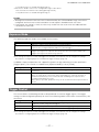
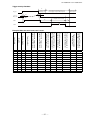
Shortest Repetition Period for Triggers
Depending on the exposure mode and image scanning range, the shortest repetition periods for
triggers are as follows.
1. Timed - Trigger Mode
Example: When [Frame Start Trigger] is [On] and [Exposure Mode] is [Timed]
Selector
Trigger Option
Trigger Source
Opt In Filter Selector
Overlap
Pixel Format
Exposure Time
Value
Off
Line4-TTL in 1
Off
Read Out
8-bit
15 μs
Scanning range
Full
ROI 2/3 (Height 2048 x Width 2720)
ROI 2/3 (Height 1536 x Width 2048)
ROI 2/3 (Height 768 x Width 1024)
ROI 2/3 (Height 384 x Width 512)
Binning 2 x 1, 2 x 2, 1 x 2* Full
Shortest period trigger
5.276
2.478
1.686
0.860
0.447
5.276
*SP-12000M-CXP4 only
t1
Trigger
CMOS exposure
t2
Exposure active
Exposure duration
t3
FVAL
t1
10 µs (minimum)
t2
2.4 μ to 2.4 μ + 1L
t3
14L to 15L
Trigger overlap: Off
Sensor
Exposure
Next trigger input
allowed period
Next trigger start prohibited period
Trigger
A1
B
EEN
FVAL
— 28 —
Valid data Period
(= Height x Line Period)
C
SP-12000M-CXP4 / SP-12000C-CXP4
Trigger overlap: Readout
Exposure Time
Next trigger input
allowed period
Next trigger start prohibited period
Trigger
Next trigger start allowed period
Next trigger end prohibited period
A2
Sensor
Exposure
Exposure Time
Valid data Period
(= Height x Line Period)
B
EEN
FVAL
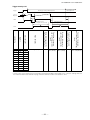
Example: When the max. frame rate is used
Link Config
Dig Bit
Sensor Dig Bit
Frame Rate [Hz]
Period from trigger
start to exposure start
[A1] (usec)
Period from trigger
start to exposure start
[A2] (usec)
Period from exposure
end to FVAL start [B]
(usec)
Period from FVAL end
to next trigger start
[C] (usec)
6G-4
6G-4
6G-2
6G-2
6G-1
6G-1
3G-4
3G-4
3G-2
3G-2
3G-1
3G-1
8
10
8
10
8
10
8
10
8
10
8
10
10
12
10
12
10
12
10
12
10
12
10
12
189.753
132.083
94.8767
76.6871
47.4947
38.3892
94.8767
76.6871
47.4947
38.3892
23.7626
19.206
2.4
2.4
2.4
2.4
2.4
2.4
2.4
2.4
2.4
2.4
2.4
2.4
2.4 to 5.8
2.4 to 7.4
2.4 to 5.9
2.4 to 7.4
2.4 to 16.0
2.4 to 19.2
2.4 to 10.8
2.4 to 16.0
2.4 to 15.5
2.4 to 18.5
2.4 to 29.5
2.4 to 34.8
52.8
48.8
51.8
48.8
194.4
156.5
122.0
127.4
194.6
156.7
384.6
308.2
–3.0
–1.9
–3.0
–1.6
8.5
10.4
18.9
45.8
7.9
6.1
17.9
23.2
Formulas for each Link Config
2.4 + (0 to 1H*)
— 29 —
Period from FVAL
end to next trigger
start [C]
2.4
(14 + Height / 2) × H*
Period from
exposure end to
FVAL start [B]
Period from trigger
start to exposure
start [A2]
Sensor Dig Bit
10
12
10
12
10
12
10
12
10
12
10
12
Period from trigger
start to exposure
start [A1]
Dig Bit
8
10
8
10
8
10
8
10
8
10
8
10
Frame Rate [Hz]
Link Config
6G-4
6G-4
6G-2
6G-2
6G-1
6G-1
3G-4
3G-4
3G-2
3G-2
3G-1
3G-1
14H (8 bit)
9H (10 bit)
0.0
SP-12000M-CXP4 / SP-12000C-CXP4
*H (Line Time) is the horizontal synchronization period and will differ depending on the camera's settings. Refer to
the maximum frame rate formula on page 27 for the formula used to calculate Line Time.
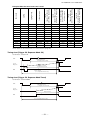
2. Trigger Width - Trigger Mode
Example: When [Frame Start Trigger] is [On] and [Exposure Mode] is [Trigger Width]
Selector
Trigger Source
Opt In Filter Selector
Overlap
Pixel Format
Exposure Time
Value
Line4-TTL in 1
Off
Read Out
8-bit
15 μs
Scanning range
Full
ROI 2/3 (Height 2048 × Width 2720)
ROI 1/2 (Height 1536 × Width 2048)
ROI 1/4 (Height 768 × Width 1024)
ROI 1/8 (Height 384 × Width 512)
Binning 2x1, 2x2, 1x2* Full
Shortest period trigger
5.273 ms
2.476 ms
1.684 ms
0.858 ms
0.445 ms
5.273 ms
*SP-12000M-CXP4 only
t1
Trigger
t3
t2
CMOS exposure
Exposure active
Exposure duration
t4
FVAL
t1
10 µs (8-bit), 15 µs (10-bit)
(minimum)
t2
4.0 μ to 4.0 μ + 1L
t3
0.6 μ to 0.6 μ + 1L
t4
14L to 15L
Trigger overlap: Off
D1
Sensor
Exposure
Next trigger input
allowed period
Next trigger start prohibited period
Trigger
C
A1
B
EEN
FVAL
— 30 —
Valid data Period
(= Height x Line Period)
SP-12000M-CXP4 / SP-12000C-CXP4
Trigger overlap: Readout
E
Next trigger start allowed period
Next trigger end prohibited period
Next trigger start
prohibited period
Trigger
Next trigger input
allowed period
D2
A2
Sensor
Exposure
Valid data Period
(= Height x Line Period)
B
F
EEN
FVAL
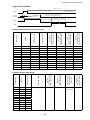
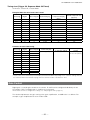
Example: When the max. frame rate is used
Link Config
Dig Bit
Sensor Dig Bit
Frame Rate[Hz]
Period from trigger start to
exposure start [A1] (usec)
Period from trigger start to
exposure start [A2] (usec)
Period from exposure end
to FVAL start [B] (usec)
Period from FVAL end to
next trigger start [C] (usec)
Period from trigger end to
exposure end [D1] (usec)
Period from trigger end to
exposure end [D2] (usec)
Trigger start prohibited
period [E] (usec)
Period from FVAL end to
next trigger start [F] (usec)
6G-4
6G-4
6G-2
6G-2
6G-1
6G-1
3G-4
3G-4
3G-2
3G-2
3G-1
3G-1
8
10
8
10
8
10
8
10
8
10
8
10
10
12
10
12
10
12
10
12
10
12
10
12
189.753
132.083
94.8767
76.6871
47.4947
38.3892
94.8767
76.6871
47.4947
38.3892
23.7626
19.206
4.0
4.0
4.0
4.0
4.0
4.0
4.0
4.0
4.0
4.0
4.0
4.0
4.0 to 7.3
4.0 to 8.9
4.0 to 10.8
4.0 to 12.4
4.0 to 17.5
4.0 to 20.9
4.0 to 10.8
4.0 to 12.4
4.0 to 17.4
4.0 to 20.9
4.0 to 31.1
4.0 to 37.7
51.8
48.8
99.4
80.7
194.4
156.5
99.7
81.0
194.6
156.7
384.5
308.3
5.4
6.8
6.3
6.9
6.4
6.6
9.9
108
9.7
9.2
9.5
5.2
0.60
0.60
0.60
0.60
0.60
0.60
0.60
0.60
0.60
0.60
0.60
0.60
0.60 to 3.9
0.60 to 5.4
0.60 to 7.4
0.60 to 8.9
0.60 to 14.2
0.60 to 17.2
0.60 to 7.4
0.60 to 8.9
0.60 to 14.1
0.60 to 17.4
0.60 to 27.5
0.60 to 34.2
24.0
16.4
23.0
32.0
24.0
35.0
24.0
35.0
25.0
31.0
23.0
31.0
–14.1
–0.34
–0.29
4.0
9.7
108
8.4
-0.1
6.0
6.9
4.5
4.2
— 31 —
SP-12000M-CXP4 / SP-12000C-CXP4
Formulas for each Link Config
Sensor Dig Bit
Frame Rate[Hz]
Period from trigger start to
exposure start [A1] (usec)
Period from trigger start to
exposure start [A2] (usec)
Period from exposure end
to FVAL start [B] (usec)
Period from FVAL end to
next trigger start [C] (usec)
Period from trigger end to
exposure end [D1] (usec)
Period from trigger end to
exposure end [D2] (usec)
10
12
10
12
10
12
10
12
10
12
10
12
(14 + Height / 2) × H*
4.0
4.0 +
(0 to 1H*)
14H (8 bit)
9H (10 bit)
0.0
0.60
0.60 +
(0 to 1H)
Period from FVAL end to
next trigger start [F] (usec)
Dig Bit
8
10
8
10
8
10
8
10
8
10
8
10
Trigger start prohibited
period [E] (usec)
Link Config
6G-4
6G-4
6G-2
6G-2
6G-1
6G-1
3G-4
3G-4
3G-2
3G-2
3G-1
3G-1
50.0
15.0
*H (Line Time) is the horizontal synchronization period and will differ depending on the camera's settings. Refer to
the maximum frame rate formula on page 27 for the formula used to calculate Line Time.
3. PIV-Trigger Mode
Example: When [Frame Start Trigger] is [On] and [Exposure Mode] is [Timed]
Selector
Trigger Option
Trigger Source
Opt In Filter Selector
Overlap
Pixel Format
Exposure Time
Value
PIV
Line4-TTL in 1
Off
Off
8-bit
15 μs
Scanning range
Full
ROI 2/3 (Height 2048 × Width 2720)
ROI 1/2 (Height 1536 × Width 2048)
ROI 1/4 (Height 768 × Width 1024)
ROI 1/8 (Height 384 × Width 512)
Binning 2 x 1, 2 x 2, 1 x 2* Full
Shortest period trigger
10.555 ms
4.964 ms
3.380 ms
1.728 ms
0.903 ms
10.555
*SP-12000M-CXP4 only
— 32 —
SP-12000M-CXP4 / SP-12000C-CXP4
Trigger overlap: Off
Next trigger input
allowed period
Next trigger start prohibited period
Trigger
A
Sensor
Exposure
E
D
C
B
EEN
Valid data Period
( = Height x Line Period)
Valid data Period
( = Height x Line Period)
FVAL
Link Config
Dig Bit
Sensor Dig Bit
Frame Rate[Hz]
Period from trigger start to
exposure start [A] (usec)
Period from 1st exposure
end to 1st FVAL start [B]
(usec)
Period from 2nd exposure
end to 2nd FVAL start [C]
(usec)
Period from FVAL end to
next trigger start [D] (usec)
Period from 1st exposure
end to 2nd exposure start [E]
(usec)
6G-4
6G-4
6G-2
6G-2
6G-1
6G-1
3G-4
3G-4
3G-2
3G-2
3G-1
3G-1
8
10
8
10
8
10
8
10
8
10
8
10
10
12
10
12
10
12
10
12
10
12
10
12
(14 + Height / 2) × H*
4.0
14H* (8 bit)
9H* (10 bit)
15H* (8 bit)
10H* (10 bit)
11.0
14H* –3.0 (8 bit)
9H* –3.0 (10 bit)
*H (Line Time) is the horizontal synchronization period and will differ depending on the camera's settings. Refer to
the maximum frame rate formula on page 27 for the formula used to calculate Line Time.
— 33 —
SP-12000M-CXP4 / SP-12000C-CXP4
Example: When the max. frame rate is used
Link Config
Dig Bit
Sensor Dig Bit
Frame Rate[Hz]
Period from trigger start
to exposure start [A]
(usec)
Period from 1st exposure
end to 1st FVAL start [B]
(usec)
Period from 2nd
exposure end to 2nd
FVAL start [C] (usec)
Period from FVAL end to
next trigger start [D]
(usec)
Period from 1st exposure
end to 2nd exposure start
[E] (usec)
6G-4
6G-4
6G-2
6G-2
6G-1
6G-1
3G-4
3G-4
3G-2
3G-2
3G-1
3G-1
8
10
8
10
8
10
8
10
8
10
8
10
10
12
10
12
10
12
10
12
10
12
10
12
189.753
132.083
94.8767
76.6871
47.4947
38.3892
94.8767
76.6871
47.4947
38.3892
23.7626
19.206
4.0
4.0
4.0
4.0
4.0
4.0
4.0
4.0
4.0
4.0
4.0
4.0
51.9
48.9
99.4
80.7
194.4
156.5
99.7
80.9
194.6
156.7
390.6
308.3
52.7
50.8
103.7
86.2
205.5
170.4
104.0
86.5
205.7
170.7
409.2
339.0
5.8
6.7
5.8
6.8
5.6
6.7
10.0
10.8
9.9
10.8
7.6
1.1
42.2
45.8
96.8
77.6
191.8
153.4
96.8
77.6
191.8
153.4
387.7
305.0
For details on the PIV function, see “PIV Function” (page 44).
Timing chart (Trigger Off, Exposure Mode Off)
Continuous, Shutter Off
FVAL
Valid data Period
(= Height x Line Period)
Sensor
Exposure
B
EEN
A
ActualExposureTime
(= Frame Period – B)
Frame Period
(= 1/ Acquisition Frame rate)
Timing chart (Trigger Off, Exposure Mode Timed)
Continuous, Shutter Mode
FVAL
Valid data Period
(= Height x Line Period)
Sensor
Exposure
ExposureTime
EEN
Frame Period
(= 1/ Acquisition Frame rate)
— 34 —
A
SP-12000M-CXP4 / SP-12000C-CXP4
Timing chart (Trigger Off, Exposure Mode Off/Timed)
Continuous, Shutter Off / Shutter Mode
Example: When the max. frame rate is used
Link Config
Dig Bit
Sensor Dig Bit
Frame Rate [Hz]
6G-4
6G-4
6G-2
6G-2
6G-1
6G-1
3G-4
3G-4
3G-2
3G-2
3G-1
3G-1
8
10
8
10
8
10
8
10
8
10
8
10
10
12
10
12
10
12
10
12
10
12
10
12
189.753
132.083
94.8767
76.6871
47.4947
38.3892
94.8767
76.6871
47.4947
38.3892
23.7626
19.206
Period from FVAL end
to exposure end [A]
(usec)
0.52
3.3
6.6
8.8
18
23
3.1
4.9
15
19
37
47
Period of exposure stop
[B] (usec)
59
59
115
101
228
199
115
101
228
199
455
395
Formulas for each Link Config
Link Config
Dig Bit
Sensor Dig Bit
Frame Rate [Hz]
6G-4
6G-4
6G-2
6G-2
6G-1
6G-1
3G-4
3G-4
3G-2
3G-2
3G-1
3G-1
8
10
8
10
8
10
8
10
8
10
8
10
10
12
10
12
10
12
10
12
10
12
10
12
(14 + Height / 2) × H
Period from FVAL end
to exposure end [A]
0 to 1H
Period of exposure
stop [B]
16H to 17H (8-bit)
11H to 12H (10-bit)
*H (Line Time) is the horizontal synchronization period and will differ depending on the camera's settings. Refer to
the maximum frame rate formula on page 27 for the formula used to calculate Line Time.
Gain Control
Digital gain is used for gain control on the camera. R and B can be configured individually for the
SP-12000C-CXP4. The digital gain is used for the master gain.
For details on how to configure the settings, see “Adjusting the Gain” (page 21).
The relationship between the gain setting value, gain amplification, and dB value is as follows. For
example, a gain amplification of x5.62 will be 15 dB.
— 35 —
SP-12000M-CXP4 / SP-12000C-CXP4
Monochrome
Gain
setting
value
Gain
amplification
1600
x16
100
x1
Gain adjustment range (monochrome)
24dB
0dB
Bayer color
Gain
Gain
setting
amplification
value
Master
X89.12
1600
39dB
Master
Red
24dB
15dB
15dB
0dB
X1
X0.45
0dB
–7dB
X7.15
0
R&B
Blue
15dB
X16
X5.62
Gain setting
value (scaling)
Gain adjustment range (Bayer color)
0dB
–7dB
-7dB
37876 (X5.62)
0 (X1)
–4533 (X0.45)
37876 (X5.62)
0 (X1)
–4533 (X0.45)
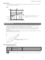
LUT (Lookup Table)
The LUT function is used to generate a non-linear mapping between signal values captured on the
sensor and those that are output from the camera. You can specify the output curve using 256 setting
points (indexes).
■■To use the LUT function
Configure the settings as follows.
Item
JAI LUT Mode
LUT Selector*
LUT Index
Setting value / selectable range
LUT
R, G, B
SP-12000M-CXP4: 0 to 255
SP-12000C-CXP4: 0 to 255
LUT Value
0 to 4095
Description
Use LUT.
Select the LUT channel to control.
Select the LUT index to configure.
Indexes represent the possible pixel values captured on the
sensor, from the lowest value (Index 0) to the highest (Index
255). For example, Index 0 represents a full black pixel and
Index 255 represents a full white pixel.
Set the LUT output value for the selected index.
*SP-12000C-CXP4 only
Note
R, G, and B are configured separately on the SP-12000C-CXP4.
— 36 —
SP-12000M-CXP4 / SP-12000C-CXP4
■■LUT values
LUT values range from 0 at the lowest to 4095 at the highest. Linear interpolation is used to calculate
LUT values between the index points.
Color
4095
Linear interpolation using data to the left and
right is used to determine values between
points.
LUT Value [1]
LUT Value [0]
Index0
Index255
Index1
Gamma Function
The gamma function corrects the output signals from the camera beforehand (reverse correction),
taking into consideration the light-emitting properties of the monitor display.
As the light-emitting properties of the monitor are not linear, the entire image may be darker or the
gradation in the dark areas may be less noticeable when camera outputs are displayed without
processing.
The gamma function can be used to correct the camera signals with an opposite-direction curve and
produce a display that is close to linear.
Example of the light-emitting properties
of the monitor display
■■To use the gamma function
Configure the settings as follows.
Item
Gamma
JAI LUT Mode
Setting value / selectable range
0.45, 0.5, 0.55, 0.6, 0.65, 0.75,
0.8, 0.9, 1.0 (9 steps)
Gamma
Description
Select the gamma correction value.
Use gamma.
Note
You can use the LUT function to configure a curve with more detailed points. For details, see “LUT (Lookup Table)”
(page 36).
— 37 —
SP-12000M-CXP4 / SP-12000C-CXP4
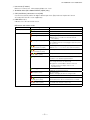
ROI (Regional Scanning Function)
The ROI (region of interest) function allows you to output images by specifying the areas to scan.
ROI Settings
Specify the area to scan by specifying width, height, and horizontal/vertical offset values under [Image
Format Control].
For details on how to configure the settings, see “Configuring the Output Format” (page 17).
You can increase the frame rate by specifying a lower height, as the number of lines scanned
decreases.
The minimum area is as follows.
Width (pixels)
Binning Off: 128
Binning 2 On: 256
The minimum value for Monochrome varies
depending on the [Binning] setting.
128
SP-12000M-CXP4
SP-12000C-CXP4
Example 1: Without binning
[Binning Horizontal] *: 1
[Binning Vertical] *: 1
Height (pixels)
16
16
Example 2: With binning
[Binning Horizontal] *: 2
[Binning Vertical] *: 2
Scanning range
Width
3072 Height Max
OffsetY
OffsetX
Height
Width
1536 Height Max
OffsetX
Scanning range
OffsetY
Height
2048 Width Max
4096 Width Max
*SP-12000M-CXP4 only
For details on the frame rates for common ROI sizes, see “Frame Rate Reference” (page 58).
— 38 —
SP-12000M-CXP4 / SP-12000C-CXP4
Video Send Mode
Switch the video send mode to configure and operate Multi ROI, Sequence Trigger, and other JAI
Custom Control functions.
Video Send Mode
■■To switch the video send mode
Select the video send mode in [Video Send Mode Selector].
[Video Send Mode Selector] option
Normal Mode
Multi Mode (Multi ROI)
Trigger Sequence Mode
Command Sequence Mode
Description
Normal camera operation.
Multi ROI mode that allows you to configure ROI settings for up to
5 images.
Sequence Trigger mode that executes presets in a predefined order based
on [Sequence Roi Frame Count] and [Sequence Roi Next Index]. Starts at
Index #1.
Sequence Trigger mode that executes the preset listed in [Command
Sequence Index] each time a trigger is received. Can jump to new preset
by sending a new index value to [Command Sequence Index].
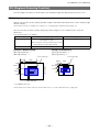
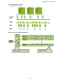
■■Multi ROI function
When the multi ROI function is enabled, you can split a frame to 32 areas, and scan specific areas.
However, as the up to 32 ROI areas are output as one frame, the [Width] setting will be common.
To enable the multi ROI function, set [Video Sending Mode Selector] to [Multi Mode].
ROI area configuration overview
when Multi ROI Index Max = 4
Video output for Multi ROI
configuration example
Specify the areas by specifying width, height, and horizontal/vertical offset values for each index under
[JAI Custom Control MultiROI].
Note
The width must be common among all ROI indexes.
— 39 —
SP-12000M-CXP4 / SP-12000C-CXP4
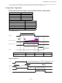
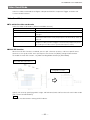
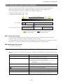
■■Sequence Trigger function
The Sequence Trigger function lets you define up to 128 preset combinations of exposure time,
gain, ROI, and other settings which can be stepped through each time a trigger is received. This is
particularly useful for quickly capturing multiple exposures of objects under inspection to adjust for
areas or components with significantly different levels of reflectance. The order of execution and the
repetition of particular presets are based on user-defined parameters stored in the sequence, as well
as the sequence mode selected in the [Video Send Mode Selector].
Two operation modes (Trigger Sequence and Command Sequence) are available for the Sequence
Trigger function.
Trigger Sequence mode
With this mode, the Sequence Trigger “pattern” is predetermined by the user. The user defines up to
128 different “indexes.” Each index represents a combination of the following parameters:
•ROI (width, height, offset X, and offset Y)
•Exposure Time
•Gain Level (R/B Gain can also be configured on the color model)
•Black Level
•Binning Mode (monochrome only)
•LUT Enable (whether or not to enable the use of LUT for this index)
•Frame Count (the number of times to repeat this index before moving to the next)
•Next Index to execute in the predetermined pattern
In addition to these individual index parameters, two other parameters are applied to the entire
sequence:
[Sequence LUT Mode] defines whether Gamma or LUT is to be applied to the sequence. If Gamma
is selected, the Gamma setting defined in the camera’s Analog Control section will be applied to all
exposures in the sequence. If LUT is selected, the LUT characteristics defined in Analog Control will
be applied to any index where [Sequence LUT enable] has been set to ON.
[Reset Sequence Index] causes the index selector to be reset to Index 1. Thus, the sequence pattern
will start over at the next trigger.
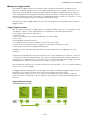
In Trigger Sequence mode, patterns always begin with Index1. Subsequent triggers follow the userdefined values in [Sequence Index Frame Count] and [Sequence ROI Next Index].
Assigning a Next Index value of “1” to an index creates a loop back to the start of the sequence
pattern. As there is no defined “end” to a sequence, the parameter called [Sequence Repetition] has
no effect.
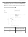
Trigger Sequence example
User-defined Indexes (up to 128)
Index1
ROI
Exposure
Gain
LUT
Binning
Frame Count = 2
Next Index = 3
Triggers /
Image
Frames
1
Index2
ROI
Exposure
Gain
LUT
Binning
Frame Count = 1
Next Index = 1
Index3
Index4
ROI
Exposure
Gain
LUT
Binning
Frame Count = 1
Next Index = 4
ROI
Exposure
Gain
LUT
Binning
Frame Count = 2
Next Index = 2
2
3
6
— 40 —
4
5
SP-12000M-CXP4 / SP-12000C-CXP4
Index structure for Trigger Sequence
Index
Selector
(MUX)
Index1
ROI1
Index2
ROI2
Index128
ROI128
Exposure
1
Exposure
Gain1
Black
Level1
Binning1
LUT
Enable1
Frame
Count1
Next
Index1
Gain2
Black
Level2
Binning2
LUT
Enable2
Frame
Count2
Next
Index2
(M/Red/Blue)
2
(M/Red/Blue)
Exposure
128
(M/Red/Blue)
(H/V)
(H/V)
Current
Index
Reset
Sequence
Index Table
・Index Next Index
Gain128
Command
・Reset Sequence Index
LUT
Black
Frame
Binning128
(H/V)
Enable128 Count128
Level128
Next
Index128
Common Settings
・Sequence LUT mode
Command Sequence mode
This mode allows the user to vary the “pattern” of the sequence in response to external factors.
Changes in the sequence can be initiated manually or in a programmatic fashion as the result of data
from sensors/controllers or from the analysis of previous images.
In this mode, the user can define up to 128 different “indexes” each incorporating a combination of:
•ROI (width, height, offset X, and offset Y)
•Exposure Time
•Gain Level (R/B Gain can also be configured on the color model)
•Black Level
•Binning Mode (monochrome only)
•LUT Enable (whether or not to enable the use of LUT for this index)
The user must also enter a value from 1 to 128 in [Command Sequence Index]. This indicates which
index to execute each time a trigger is received. The same index will continue to be executed for all
subsequent triggers as long as the value of [Command Sequence Index] remains unchanged.
Changing the value of [Command Sequence Index] to one of the other predefined indexes causes
that index to be executed in response to subsequent triggers. This mode of operation enables users to
develop applications that continually send new values to [Command Sequence Index] in response to
external factors such as changing light conditions, different types or sizes of objects being inspected,
or other factors. This allows applications to change ROI, exposure, gain, etc., without being restricted
to a predefined pattern.
As with Trigger Sequence, [Sequence LUT Mode] defines whether Gamma or LUT is to be applied
to the sequence. If Gamma is selected, the Gamma setting defined in the camera’s Analog Control
section will be applied to all exposures in the sequence. If LUT is selected, the LUT characteristics
defined in Analog Control will be applied to any index where [Sequence LUT enable] has been set to
ON.
[Sequence Index Frame Count], [Sequence ROI Next Index], and [Reset Sequence Index] are not
used in Command Sequence mode and entered values are ignored.
— 41 —
SP-12000M-CXP4 / SP-12000C-CXP4
Command Sequence Example
User-defined Indexes (up to 128)
Index1
Index2
ROI
Exposure
Gain
LUT
Binning
Command
Sequence
Index
Set to
Index1
Index3
ROI
Exposure
Gain
LUT
Binning
Set to
Index3
Set to
Index1
ROI
Exposure
Gain
LUT
Binning
Set to
Index1
Set to
Index2
Set to
Index2
Camera
Triggers
Image
Frames
Settings
Used
Index1
Settings
Index3
Settings
Index1
Settings
Index2
Settings
Index1
Settings
Index2
Settings
Index structure for Command Sequence
Index
Selector
(MUX)
Index1
ROI1
Exposure1
(M/Red/Blue)
Black
Level1
Binning1
LUT
Enable1
Index2
ROI2
Gain2
Exposure2 (M/Red/Blue)
Black
Level2
Binning2
LUT
Enable2
Black
Level128
Binning128
LUT
Enable128
Gain1
(H/V)
(H/V)
Current
Index
Index128
ROI128
Exposure
128
Common Settings
Command Sequence Index (1 to 128)
— 42 —
Gain128
(M/Red/Blue)
(H/V)
Common Settings
Sequence LUT mode
SP-12000M-CXP4 / SP-12000C-CXP4
ALC (Automatic Level Control) Function
The ALC (automatic level control) function combines the automatic gain control and automatic
exposure control functions, and is capable of handling changes in various brightnesses.
The function operates as follows in response to changes in brightness.
Change from bright to dark: ASC AGC
Change from dark to bright: AGC ASC
Dark
AGC operation
ASC (auto shutter) operation
AGC
Max
Change in brightness
AGC operation
Fixed at min. gain value
Max. to min. (user specified)
Fixed at max. ASC value
Bright
ASC operation
Max. to min. (user specified)
Operation during change
from dark to bright
Fixed at min. ASC value
Operation during change
from bright to dark
■■To use the ALC function
Set [Gain Auto] or [Exposure Auto] or both to [Continuous] mode. Configure the minimum value,
maximum value, etc. for AGC and ASC under [JAI Custom Control].
The target video levels for AGC and ASC are configured in [ALC Reference]. For example, when [ALC
Reference] is set to 100%, video levels will be maintained at 100% for AGC and ASC.
■■Automatic gain level control
Set [Gain] to [Continuous].
Detailed Settings for Gain Auto (Automatic Gain Level Control)
When [Gain Auto] is set to [Continuous], you can configure the conditions for automatic adjustment in
detail.
Item
ALC Reference
ALC Area Enable All
ALC Area Selector
ALC Area Enable
AGC Max.
AGC Min.
AGC/ASC Control Speed
Description
Specify the target level for automatic gain control. (This setting is
also used for automatic exposure control.)
Select whether to specify all areas as auto gain metering areas
or whether to specify the areas individually.
[0]: Specify areas as auto gain metering areas (16 areas)
individually.
[1]: Specify all areas as auto gain metering areas.
Individually select any of 16 areas for automatic gain metering.
(This setting is also used for automatic exposure control.)
Select [True] to enable the metering area selected in [ALC Area
Selector], or select [False] to disable it.
Specify the maximum value for the automatic gain control range.
Specify the minimum value for the automatic gain control range.
Specify the reaction speed for automatic gain control. (This
setting is also used for automatic exposure control.)
— 43 —
SP-12000M-CXP4 / SP-12000C-CXP4
Auto gain metering areas (16 areas)
High
Left
High
Mid-left
High
Mid-right
High
Right
Mid-High
Left
Mid-High
Mid-left
Mid-High
Mid-right
Mid-High
Right
Mid-Low
Left
Mid-Low
Mid-left
Mid-Low
Mid-right
Mid-Low
Right
Low
Left
Low
Mid-left
Low
Mid-right
Low
Right
PIV Function
The PIV function allows you to perform exposure and scanning twice in succession in response to a
single trigger. This is useful in situations that require quick successive image scans.
The durations for the first and second exposures are different. The first exposure time can be
configured freely by the user. After a minimum interval, the second exposure time lasts for one frame.
To capture two images of the same brightness, use a strobe light in a dark room, for example.
Trigger
Exposure
1st
exposure
Strobe light
2nd exposure
Strobe light
Strobe light
Video Out
1st video out
— 44 —
2nd video out
SP-12000M-CXP4 / SP-12000C-CXP4
HDR (High Dynamic Range) Mode (SP-12000M-CXP4 only)
HDR (high dynamic range) mode is a function that uses the exposure time configured with [Exposure
Time] as a base, and allows you to determine input level positions for knee points. You can change the
number of knee points from 1 to 2.
Adjust the [Knee Point 1], [Knee Point 2], [Knee Slope 2], and [Knee Slope 3] settings to configure the
settings.
Overview of knee point configurations during HDR mode
Exposure duration
Scan duration
[Knee Point 2] setting range
[Knee Point 1] setting range
[Exposure Time] [Knee Slope 2] or lower
Item
Setting value / selectable range
HDR Mode
On / Off
Exposure Time
15 µs (8-bit),
20 µs (10-bit)
to 7999999
Knee Slope 2
2 to 16
(step=1)
Description
When [Exposure Mode] is set to [Timed] and [HDR
Mode] is set to [On], HDR mode is enabled.
[Unit: us]
Specify the exposure duration for HDR mode.
The knee points during HDR mode are determined
by the [Exposure Time] value.
Use this to determine the position of knee point 1
based on the [Exposure Time] value.
The knee slope 2 value is a value by which the
[Exposure Time] will be divided.
— 45 —
SP-12000M-CXP4 / SP-12000C-CXP4
Item
Setting value / selectable range
Description
Knee Slope 3
2 to 16
(step=1)
Use this to determine the position of knee point 2
based on the [Exposure Time] value.
The knee slope 3 value is a value by which the
[Exposure Time] will be divided.
Knee Point 1
10 to 120
(step =1)
[Unit: %]
Adjust the output level for knee point 1.
The [Knee Point 1] setting value must always be
less than or equal to that of [HDR Knee Point 2].
You can determine the knee point 1 value using the
following formula: [Exposure Time] - ([Exposure
Time] ÷ [Knee Slope 2]).
Knee Point 2
10 to 120
(step =1)
[Unit: %]
Adjust the output level for knee point 2.
You can determine the knee point 2 value using the
following formula: [Exposure Time] - ([Exposure
Time] ÷ [Knee Slope 3]).
The relationship between the number of knee points
and knee slope 2 and 3 is as follows.
(1) Settings for two knee points and three knee
slopes
[Knee Slope 2] ≤ [Knee Slope 3]
(2) Settings for one knee point and two knee slopes
[Knee Slope 2] > [Knee Slope 3] and
[Knee Point1] > [Knee Point 2]
(3) Settings for no knee points and one knee slope
[HDR Mode] = [Off]
Read Slope Number
Command
—
Use this command to read the number of knee
points generated via the [Knee Point 1], [Knee Point
2], [Knee Slope 2], and [Knee Point 3] settings from
the camera.
— 46 —
SP-12000M-CXP4 / SP-12000C-CXP4
Video Process Bypass Mode
The Video Process Bypass mode is a function that bypasses internal image processing on the camera.
On the SP-12000, DSNU correction and shading, gain, blemish, and black level adjustment are
normally performed on the sensor output signal. However, when the Video Process Bypass mode is
used, images can be imported to the system without image processing* being performed internally
on the camera. The Video Process Bypass mode is ideally used in cases where image processing is
performed by the system.
In addition, images are output from the camera in 12-bit format only when the Video Process Bypass
function is used.
*Excluding DSNU correction and black level adjustment.
■■Available bit-depth options
CXP output
Sensor output
10-bit
12-bit
8-bit
10-bit
12-bit
When bypass is enabled, the sensor output and camera output data can be set to the same bit width.
Operating using 12-bit outputs must be performed in bypass mode.
CXP output
Sensor output
DSNU Correction
Black Adjust Set
Pixel Gain
Shading Correction
Blemish Compensation
Binning
LUT/Gamma
Black SETUP
Test Pattern
Camera output
Video Process
Bypass Off
Video Process
Bypass On
8/10 bit
8/10/12 bit
Differences in camera operation
■■When Video Process Bypass mode is disabled
All video processes are enabled.
Sensor
Block
DSNU
Correction
Block
Black
Adjust
Block
Pixel
Gain
Block
Shading
Correction
Block
Blemish
Compensate
Block
Binning
Block
LUT/Gamma
Block
Black
Setup
Block
■■When Video Process Bypass mode is enabled
All video processes except DSNU Correction Block, Black Adjust Block, Blemish Compensate Block
and Black Setup Block are disabled.
Sensor
Block
DSNU
Correction
Block
Black
Adjust
Block
Blemish
Compensate
Block
— 47 —
Black
Setup
Block
SP-12000M-CXP4 / SP-12000C-CXP4
Settings List
Feature Properties
Regarding the bold and underlined “selector” settings in this list, the various related settings will be
stored separately for each selector option.
: Settings that can only be configured when image acquisition on the camera is stopped.
Item
Setting range
Default value
—
a) Device Control
Standard
—
0xC0A79AE5(3,232,209,637)
Revision
—
0x00010000(65,536)
XmlManifestSize
—
1
XmlManifestSelector
XmlMajorVersion
XmlMinorVersion
XmlSubMinorVersion
XmlSchemaVersion
XmlUrlAddress
0
—
—
—
—
—
0
1
0
—
0×00010100(65792)
0×00007000(28672)
IidcPointer
—
0
DeviceVendorName
DeviceModelName
—
—
DeviceManufactureInfo
DeviceVersion
DeviceFirmwareVersion
DeviceFpgaVersion
DeviceFirmware2Version
—
—
—
—
—
JAI Ltd, Japan
SP-12000M-CXP4 or
SP-12000C-CXP4
See the possibilities
—
—
—
—
DeviceFpga2Version
—
—
DeviceID
DeviceUserId
LinkReset
DeviceLinkId
MasterHostLinkId
ControlPacketDataSize
—
Any
1
—
—
—
0
1
2
StreamPacketDataSize
LinkConfig
3072
CXP3_X4(0x00040038)
TestMode
16 to 4096
CXP6_X4(0x00040048)
CXP6_X2(0x00020048)
CXP6_X1(0x00010048)
CXP3_X4(0x00040038)
CXP3_X2(0x00020038)
CXP3_X1(0x00010038)
"CXP3_X4
0x00040038(262200)"
0,1
TestErrorCountSelector
—
0
TestErrorCount
—
0
DeviceTemperatureSelector
SensorBoard,
MainBoard,
InterfaceBoard
SensorBoard
LinkConfigDefault
—
2
"CXP3_X4
0x00040038(262200)"
0
— 48 —
Description
Displays/configure information related to
the device.
Displays the magic number which
indicates that the CoaXPress standard is
implemented.
Displays revisions to the CoaXPress
standard.
Displays the number of XML manifests
that can be used.
Select the XML to use.
Displays the XML version.
Displays the XML version.
Displays the XML version.
Displays the XmlSchema version.
Displays the XML URL string starting
address.
Displays the IIDC register area starting
address. As this is not supported, 0 is
displayed.
Displays the manufacturer name.
Displays the model name.
Displays the device information.
Displays the hardware version.
Displays the firmware version.
Displays the FPGA version.
Displays the CPU2 firmware version. (not
used)
Displays the FPGA2 firmware version.
(not used)
Displays the device ID.
Set the user ID for the camera.
Reset the link.
Displays the device link ID.
Displays the host link ID.
Configure the maximum control data
packet size that the host can scan from
the device and that can be written to the
device (4-byte increments).
Set the packet size for the stream.
Configure the LinkConfig settings.
Displays the LinkConfig value for
operation in the device's default mode.
When 0x00000001 entered, enable/
disable transmission of test packets from
the device to the host. When enabled,
the packet of the current 1024 test word
is transmitted.
Set the TestErrorCount register that will
be required.
Displays the error count for the current
link in regards to the device-side link ID
stored on the TestErrorCountSelector
register.
Select the area of the camera's interior
for which to display the temperature
sensor's reading.
SP-12000M-CXP4 / SP-12000C-CXP4
Item
Setting range
Default value
DeviceTemperature
—
—
DeviceReset
b) Image Format Control
SensorWidth
SensorHeight
SensorDigitizationTaps
—
—
4096
3072
10bit
WidthMax
HeightMax
Width
Height
OffsetX
OffsetY
BinningHorizontal
—
—
10bit
12bit
4096
3072
128 to 4096
16 to 3072
0 to 3968
0 to 3056
1, 2
BinningVertical
1, 2
1
PixelFormat
SP-12000M-CXP4:
8 Bit Monochrome,
10 Bit Monochrome,
12 Bit Monochrome
(Video Process Bypass
mode only)
SP-12000C-CXP4:
8 Bit BayerGB,
10 Bit BayerGB,
12 Bit BayerGB
(Video Process Bypass
mode only)
Off,
Grey Horizontal Ramp,
Grey Vertical Ramp,
Grey Horizontal
RampMoving,
HorizontalColorBar
(color only),
VerticalColorBar (color
only),
MovingColorBar (color
only)
0: Tap_1X_1Y
SP-12000M-CXP4:
8 Bit Monochrome
SP-12000C-CXP4:
8 Bit BayerGB
TestPattern
TapGeometry
c) Acquisition Control
AcquisitionMode
AcquisitionStart
AcquisitionStop
AcquisitionFrameCount
Acquisition Frame Rate*
* Frame period depends on
ROI, pixel format, and
binning mode selected."
AcquisitionStatusSelector
AcquisitionStatus
TriggerSelector
TriggerMode
TriggerSoftware
TriggerSource
TriggerActivation
TriggerOverlap
ExposureMode
4096
3072
4096
3072
0
0
1
Description
Displays the internal temperature (°C) of
the camera.
Reset the device.
Configure image format settings.
Displays the maximum image width.
Displays the maximum image height.
Displays the digital tones output from the
sensor.
Displays the maximum image width.
Displays the maximum image height.
Set the image width.
Set the image height.
Set the horizontal position.
Set the vertical position.
Set the number of pixels in the horizontal
direction for which to perform binning.
Set the number of pixels in the vertical
direction for which to perform binning.
Set the pixel format.
Off
Select the test image.
0: Tap_1X_1Y
Displays the TapGeometry settings.
Configure image acquisition settings.
Select the image acquisition mode.
Start image acquisition.
Stop image acquisition.
In [Multi Frame] mode, set the number of
frames to acquire.
In [Multi Frame] mode, set the number of
frames to acquire.
—
—
1 to 65535
Continuous
—
—
153
0.125 to 189.7*
94.8767
* The fastest value depends on the
setting of the Link Config.
Acquisition Start,
Acquisition End,
Frame Start
Off, On
—
Low, High, Software, P
ulse Generator 0,
User Output 0,
User Output 1,
Line 4, Line 5,
Line 10, Line11,
NAND0 Out,
NAND1 Out
Rising Edge,
Falling Edge,
Level High, Level Low
Off, On
Off, Timed,
Trigger Width
Frame Start
Select the trigger operation.
Off
—
Line 4
Select the trigger mode.
Execute a software trigger
Select the trigger signal source.
Rising Edge
Select the polarity of the trigger signal
(i.e., location of signal at which trigger is
applied).
Select the trigger overlap operation.
Select the exposure mode.
Off
Timed
— 49 —
SP-12000M-CXP4 / SP-12000C-CXP4
Item
Setting range
Default value
15@8bit
20@10bit
to 7999999
15@8bit
20@10bit
to 7999999
Off, Continuous
10486
SP-12000M-CXP4:
Digital All
SP-12000C-CXP4:
Digital All,
Digital Red,
Digital Blue
DigitalAll: 1 to 16
DigitalRed,Blue: 0.4467
to 56235
DigitalAll: 100 to 1600
DigitalRed: –4533 to
37876
SP-12000M-CXP4:
RawDigital All
SP-12000C-CXP4:
RawDigital All,
RawDigital Red,
RawDigital Blue
RawDigitalAll -133 to
255
l,RawDigitalRed,
RawDigitalBlue -133 to
255
Off, Once, Continuous
Off, On
Off, Gamma, LUT
1.0 to 0.45
Digital All (master gain)
Line1 - TTL Out 1
LineMode
Line1 - TTL Out 1,
Line2 - Opt Out 1,
Line4 - TTL In 1,
Line5 - Opt In 1,
Line7 - CXP In,
Line8 - TTL Out 2,
Line9 - TTL Out 3,
Line10 - TTL In 2,
Line11 - LVDS In,
NAND Gate 0 In 1,
NAND Gate 0 In 2,
NAND Gate 1 In 1,
NAND Gate 1 In 2
—
LineInverter
True, False
False
LineStatus
—
—
LineSource
Low, High,
Acquisition Trigger Wait,
Frame Trigger Wait,
Frame Active,
Exposure Active,
FVAL,
User Output 0 to 3,
Line 4 - TTL In 1,
Line 5 - Opt In 1,
Line10 - TTL In 2,
Line11 - LVDS In,
Pulse Generator 0 to 3,
Nand 0 Out, Nand 1
Out
—
User Output 0,
User Output 1,
User Output 2,
User Output 3
True, False
Low
ExposureTime
ExposureTimeRaw
ExposureAuto
d) Analog Control
GainSelector
Gain
GainRaw
BlackLevelSelector
BlackLevel
GainAuto
BalanceWhiteAuto
LutMode
Gamma
e) Digital IO Control
LineSelector
LineFormat
UserOutputSelector
UserOutputValue
f) Pulse Generators
10486
Off
Description
Set the exposure time. The maximum
value varies depending on the
[Acquisition Frame Rate Raw] value.
Set the raw exposure time.
Set whether to enable auto exposure.
Configure analog control settings.
Select the gain to configure.
Master gain: 1
R, B: 1
Set the gain value.
Digital All: 100
Digital Red & Blue: 0
Set the raw gain value.
RawDigital All (master
black)
Select the black level to configure.
0
Set the black level value.
Off
Off
Off
0.45
Enable/disable gain auto control.
Enable/disable auto white balance.
Select the JAI LUT mode.
Set the gamma value.
Configure settings for digital input/output.
Select the input/output to configure.
Output
TTL Out
User Output 0
False
— 50 —
Displays the input/output status (whether
it is input or output).
Enable/disable polarity inversion for the
selected input signal or output signal.
Displays the status of the input signal or
output signal (True: High, False: Low).
Select the line source signal for the item
selected in [Line Selector].
Displays the current I/F type.
Set the user output signal.
Configure pulse generator settings.
SP-12000M-CXP4 / SP-12000C-CXP4
Item
Setting range
Default value
PreScaler
1 to 4096
1
PulseGeneratorSelector
Pulse Generator 0
PulseGeneratorLength
Pulse Generator 0,
Pulse Generator 1,
Pulse Generator 2,
Pulse Generator 3
1 to 1048575
PulseGeneratorStartPoint
0 to 1048574
0
PulseGeneratorEndPoint
1 to 1048574
1
PulseGeneratorRepeatCount
0 to 255
0
PulseGeneratorClearActivation
Off,
High Level,
Low Level,
Rising Edge,
Falling Edge
Low, High,
Acquisition Trigger Wait,
Frame Trigger Wait,
Frame Active,
Exposure Active,
FVAL,
User Output 0,
User Output 1,
Line4 - TTL In 1,
Line5 - Opt In 1,
Line7 - CXP In,
Line10 - TTL In 2,
Line11 - LVDS In,
Nand 0 Out, Nand 1
Out
True, False
Off
Async Mode,
Sync Mode
Async Mode
R, G, B
0 to 255
0 to 4095
R
0
0
Default, User Set1 to 3
—
—
Default (factory default
values)
—
—
TriggerOption
Off,PIV
Off
ALCReference
ALCAreaSelector
ALCAreaEnable
10 to 100
Low Right to High Left
True, False
50
Low Right
False
ALCAreaEnableAll
AutoShutterControlExposureMin
0 to 1
100 to 7999998
1
100
AutoShutterControlExposureMax
101 to 7999999
7999999
AutoGainControlGainRawMin
100 to 1599
100
AutoGainControlGainRawMax
101 to 1600
1600
ALCControlSpeed
Min(1) to Max(8)
4
AWBAreaSelector
Low Right to High Left
Low Right
AWBAreaEnable
True, False
False
PulseGeneratorClearSource
PulseGeneratorInverter
PulseGeneratorClearSyncMode
g) LUTControl
LutSelector
LutIndex
LutValue
h) UserSetControl
UserSetSelector
UserSetLoad
UserSetSave
1
Description
Set the division value for the prescaler
(12-bit) using the pixel clock as the base
clock.
Select the pulse generator.
Set the count-up value (clock value) for
the pulse generator.
Set the active output start count value for
the pulse generator.
Set the active output stop count value for
the pulse generator.
Set the repeat count for the pulse
generator.
Set the clear signal condition for the
count clear input of the pulse generator.
Low
Select the count clear input signal
source.
False
Select whether to invert the polarity of the
count clear input signal.
Select the sync mode for the count clear
input signal.
Configure LUT settings.
Select the LUT channel to control.
Set the LUT index table number.
Set the LUT value.
i) JAICustomControl
— 51 —
Select the user settings.
Load user settings.
Save the current setting values as user
settings.
Configure JAI ALC settings. These
settings are also used for AGC (auto gain
control).
When [ExposureMode] is set to [Timed],
select from normal trigger operation or
PIV operation.
Set the target level for ALC. (unit: %)
Select an ALC metering area.
"Enable/disable the metering area where
selected metering area."
Set whether to enable ALC for all areas.
Set the minimum value for the ASC
range.
Set the maximum value for the ASC
range.
Set the minimum value for the AGC
range.
Set the maximum value for the AGC
range.
"Set the reaction speed for AGC/ASC.
These settings are also used for auto
exposure control."
Select the AWB (auto white balance)
measurement area.
Enable/disable the selected
measurement area.
SP-12000M-CXP4 / SP-12000C-CXP4
Item
Setting range
Default value
AWBAreaEnableAll
BlemishReductionEnable
0 to 1
True, False
1
True
BlemishReductionCalibration
—
—
BlemishDetectThreshold
0 to 100
0
BlemishDataIndex
0 to 1000
0
BlemishDataPositionX
BlemishDataPositionY
BlemishDataNum
–1 to 4095
–1to 3071
0 to 1000
–1
–1
—
ShadingMode
SP-12000M-CXP4
Flat Shading (fixed)
SP-12000C-CXP4
Flat Shading,
Color Shading
Off, User 1, User 2,
User 3
Flat Shading
ShadingCalibration
0
—
DsnuCorrect
DsnuDetect
Off, On
0
Off
—
VideoSendModeSelector
Normal Mode,
Trigger Sequence
Mode,
Command Sequence
Mode, Multi Mode
Index 1to 128
1 to 255
Index 1 to 128, Off
Normal Mode
128 to 4096/16 steps
16 to 3072/2 steps
0 to 3968/16 steps
0 to 3056/2 steps
100 to 1600
0.4467 to 56235
0.4467 to 56235
15@8bit
20@10bit
to 7999999
–133 to 255
Off, On
1 to 2
4096
3072
0
0
100
0
0
10486
1 to 2
1
1 to 255
Index 1 to 128
Index 0 to 31
128 to 4096/16 steps
1
Index 1
Index 1
4096
MultiRoiHeight
16 to 3072/2 steps
3072
MultiRoiOffsetX
0 to 3968/16 steps
0
MultiRoiOffsetY
0 to 3056/2 steps
0
MultiRoiIndexMax
Video Process Bypass
Index 0 to 31
Off, On
Index 1
Off
HDRModeSelector
0, 1
0
ShadingCorrectionMode
SequenceRoiIndex
SequenceRoiFrameCount
SequenceRoiNextIndex
SequenceRoiWidth
SequenceRoiHeight
SequenceRoiOffsetX
SequenceRoiOffsetY
SequenceRoiGain
SequenceRoiGainR
SequenceRoiGainB
SequenceRoiExposureTime
SequenceRoiBlackLevel
SequenceRoiLutEnable
SequenceRoiHBinning
(SP-12000M-CXP4 only)
SequenceRoiVBinning
(SP-12000M-CXP4 only)
SequenceRoiRepetition
NextSequenceIndex
MultiRoiIndex
MultiRoiWidth
Off
Index 1
1
Index 1
0
Off
1
— 52 —
Description
Enable/disable the all measurement area.
Set whether to enable white blemish
correction.
Set whether to enable white blemish
correction.
Set the white blemish detection
threshold.
Select the index table for the white
blemish detection position.
Set the horizontal position.
Set the vertical position.
Displays the number of blemish
correction points executed.
Select the shading correction mode.
Select whether to use shading correction.
When using the function, select the user
area to which to save the shading
correction value.
Execute shading correction. After
execution, the shading correction value is
automatically saved to the selected user
area.
Enable/disable DSNU correction.
Re-adjust the correction data for DSNU
correction.
Select the video send mode.
Select the sequence ROI index table.
Set the frame count.
Select the next index.
When [Off] is selected, sequence
operation will stop with this index.
Set the width.
Set the heigh.
Set the horizontal position.
Set the vertical position.
Set the gain value.
Set the exposure time.
Set the black level.
Set whether to enable the LUT.
Set the number of pixels in the horizontal
direction for which to perform binning.
Set the number of pixels in the vertical
direction for which to perform binning.
Set the repeat count for the sequence.
Set the sequence index command.
Set the Multi ROI index table.
Set the width. When binning is enabled
on the SP-12000M-CXP4, the maximum
value will change.
Set the height. When binning is enabled
on the SP-12000M-CXP4, the maximum
value will change.
Set the horizontal position. When binning
is enabled on the GO-5000M-USB, the
maximum value will change.
Set the vertical position. When binning is
enabled on the SP-12000M-CXP4, the
maximum value will change.
Set the Multi ROI index count.
Set whether to bypass the areas on
which DigitalGain is applied within the
FPGA.
Enable/disable HDR.
SP-12000M-CXP4 / SP-12000C-CXP4
Item
Setting range
Default value
HDRKneeSlope2
HDRKneeSlope3
HDRKneePoint1
2 to 16
2 to 16
10 to 120
2
2
100
HDRKneePoint2
10 to 120
100
BinningGainEnable
0, 1
0
OptInFilterSelector
0 to 6
0
StreamOption
0, 1
0
Counter 0 to 3
Off,
Frame Trigger,
Frame Start,
Exposure Start,
Exposure Transfer End
Rising Edge,
Falling Edge
—
—
—
—
—
Off
j)CounterAndTimer Control
Counter0 to 3
Counter0 to 3 EventSource
Counter0 to 3
EventActivation
Counter0 to 3 Reset
Counter0 to 3 Refresh
Counter0 to 3 Value
Counter0 to 3 Status
Description
Set the second HDR slope.
Set the third HDR slope.
Set the level at which to switch the first
and second HDR slopes.
Set the level at which to switch the
second and third HDR slopes.
Set whether to add pixels or average
pixels during Binning.
Set the digital filter time for the Opto
input.
Set whether to optimize the stream
packet interval according to the frame
rate or use the fastest interval.
Configure counter settings. (This camera
only supports counter functions.)
Select the counter.
Select the counter event signal for which
to read the count value.
—
Specify the timing at which to count.
—
—
0
Counter Active
Reset the counter.
Update the count value.
Displays the count value.
Displays the counter status.
Settings
For details on the setting items, refer to the JAI Control Tool User’s Guide
Item
32-bit Factory Transport Layers
Available 32-bit Transport Layers
Active_Silicon_FireBird
Transport name
Full path to cti file
Enabled
Display name
AvalData
Transport name
Full path to cti file
Enabled
Display name
BitFlow_CXP_Framegrabber
Transport name
Full path to cti file
Enabled
Display name
64-bit Factory Transport Layers
Active_Silicon_FireBird
Transport name
Full path to cti file
Enabled
Display name
AvalData
Transport name
Full path to cti file
Enabled
Display name
BitFlow_CXP_Framegrabber
Transport name
Full path to cti file
Enabled
Display name
Asynchronous Image Recording
Recording Count
Recording Skip Count
Setting range
—
—
—
True, False
—
—
—
True, False
—
—
—
True, False
—
—
Default value
Transport Layers
TLActiveSilicon
Active_Silicon_FireBird
TLActiveSilicon.cti
False
TLActiveSilicon
AvalData
AvalData
avaldata.tf.GenTL.cti
False
AvalData
BitFlow_CXP
BitFlow_CXP_Framegrabber
BFGTL.cti
False
BitFlow_CXP
—
True, False
—
TLActiveSilicon
Active_Silicon_FireBird
C:\program Files\Active Silicon\
FireBird CXP\GenTL\win64\
TLActiveSilicon.cti
False
TLActiveSilicon
AvalData
AvalData
avaldata.tf.GenTL.cti
False
AvalData
BitFlow_CXP
BitFlow_CXP_Framegrabber
BFGTL.cti
False
BitFlow_CXP
—
—
025
000
True, False
—
—
True, False
—
—
— 53 —
SP-12000M-CXP4 / SP-12000C-CXP4
Item
Setting range
Recording mode
Optimize the AVI-file creation for Mono8
Prompt user for AVI Encoder
CXP Transport Layer
Sync Remote And Local Devices
File Save
File Format
Encoder parameter
Look-and-feel
Visibility Level
HEX display
Display ToolTips
Floating-Point Display Notation
Floating-Point Display Precision
Display the Remote device layer at the top of the tree
(transport at the bottom)
Refresh Property Grid After Editing
Override TrackBar Floating-point display precision
settings
Make the control tool appear on top of images
Timestamp display format
Plugins
Search path for plugin DLLs
Enable the plug-in button on the menu tab
Support
Open settings file after save
Support EMail Address
Logging Properties
Enable logging
Use custom properties file
Custom logging properties file path
Output log file path
Enable GenApi logging
Enable GenTL logging
Enable CIProtocol logging
Enable USB logging
Log Level
Format string
Append To Log file
Video Display
Stretch Live Video
Restore Live Video Window
Skip image display when busy
Enable Color Interpolation
Color Interpolation
Show Zoom Navigation window
Show Cursor Information window
Enable Mouse Zoom
Enable Mouse Cursor Display
Default value
List, CyclicBuffer
True, False
True, False
List
True
True
True, False
True
Tiff, Jpeg, Bmp, Jai, RAW
—
Tiff
075
Beginner, Expert, Guru
True, False
True, False
Automatic, Fixed, Scientific
—
True, False
Beginner
False
True
Automatic
005
True
True, False
True, False
False
False
True, False
Ticks, MSec, PTP
False
Ticks
—
True, False
.\plugins
False
True, False
—
True
[email protected]
True, False
True, False
False
False
True, False
True, False
True, False
True, False
FATAL, ALERT, CRIT, ERROR,
WARN, NOTICE, INFO, DEBUG,
NOTEST
—
True, False
False
False
False
False
INFO
True, False
True, False
True, False
True, False
BayerStandard,
BayerStandardMultiprocessor,
BayerExtended,
BayerExtendedMultiprocessor,
BayerSimple,
BayerSimpleMultiprocessor,
BayerFast,
BayerFastMultiprocessor
True, False
True, False
True, False
True, False
True
True
True
True
BayerStandard
— 54 —
LOG %d %x: %c :%m%n
FALSE
True
False
True
False
SP-12000M-CXP4 / SP-12000C-CXP4
Miscellaneous
Updates
You can obtain update information from the following URL.
http://www.jai.com/EN/Partner/CameraInformation/Pages/Revision_Notes.aspx
*Registration and login are required for viewing.
Check the version of the unit, and update if necessary.
You can check the version of the unit under [Device Control] in the [Feature Properties] tab after
starting Control Tool.
Troubleshooting
Check the following before requesting help. If the problem persists, contact your local JAI distributor.
■■Power supply and connections
Problem
The POWER / TRIG LED remains lit amber and
does not turn green, even after power is
supplied to the camera.
Cause and solution
Camera initialization may not be complete due to lack of a
CXP connection. Check the CXP cable conection.
■■Image display
Problem
Gradation in dark areas is not noticeable.
Cause and solution
Use the gamma function to correct the display.
As the light-emitting properties of the monitor are not linear,
the entire image may be darker or the gradation in the dark
areas may be less noticeable when camera outputs are
displayed without processing. Using the gamma function
performs correction to produce a display that is close to
linear.
For details, see “Gamma Function” (page 37).
■■Settings and operations
Problem
Settings cannot be saved to user memory.
I want to restore the factory default settings.
Cause and solution
You cannot save to user memory while images are being
acquired by the camera. Stop image acquisition before
performing the save operation.
Load [Default] under [User Set Selector] in the [Feature
Properties] tab to restore the factory default settings.
— 55 —
SP-12000M-CXP4 / SP-12000C-CXP4
Specifications
Item
SP-12000M-CXP4
Scanning system
SP-12000C-CXP4
Progressive scan, 1 tap
Synchronization
Internal
Interface
CoaXPress Ver. 1.0
Image sensor
APS-C monochrome CMOS
Aspect ratio
Image size (effective image)
22.5 (H) × 16.9 (V), 28.16 mm diagonal
Pixel size
5.5 (H) × 5.5 (V) µm
Effective image pixel output
Acquisition Frame
Rate (max)
❖❖ The minimum
value is 0.125
fps for all.
8-bit
4096 (H) × 3072 (V)
4096 (H) × 3072 (V)
189 fps
189 fps
H1, V2
189 fps
N/A
H2, V1
189 fps
N/A
H2, V2
189 fps
N/A
132 fps
132 fps
H1, V1
Binning
10-bit
H1, V1
Binning
H1, V2
132 fps
N/A
H2, V1
132 fps
N/A
H2, V2
132 fps
N/A
At 10-bit output
35.54p (λ = 525 nm)
40.45 dB
At 10-bit output
49.24p (λ = 525 nm)
36.63 dB
53 dB (typical)
(0 dB gain, Black)
50 dB (typical)
(0 dB gain, Green Black)
EMVA 1288 parameters
Absolute sensitivity
Maximum SN ratio
SN ratio (traditional method)
Digital image
output format
4096 (H) × 3072 (V)
Bayer 4096 (H) × 3072 (V)
128 to 4096, 16 pixels/step
128 to 4096, 16 pixels/step
Offset X
0 to 3968, 16 pixels/step
0 to 3968, 16 pixels/step
Height
16 to 3072, 2 lines/step
16 to 3072, 2 lines/step
Offset Y
0 to 3056, 2 lines/step
0 to 3056, 2 lines/step
1
4096 (H)
4096 (H)
2
2048 (H)
—
1
3072 (V)
3072 (V)
Full pixel
ROI
Binning
Width
H
V
2
Pixel Format
Acquisition modes
Trigger selector
APS-C Bayer color CMOS
4:3
1536 (V)
—
Mono8, Mono10
BayerGB8, BayerGB10
Continuous, Single Frame, Multi Frame (1 to 65535)
Acquisition
Acquisition Start, Acquisition Stop
Exposure
Frame Start
Exposure modes
Off, Timed (EPS), Trigger Width (PWC)
Trigger options
OFF, PIV
Trigger overlap
Read Out, Off
Trigger input signals
Line 4 (TTL Input1), Line 5 (Opto Input), Line7 (CXP In),
Line 10 (TTL Input2), Line 11 (LVDS Input),
Software, PG (0-3), NAND Out (0-1)
Option filter
Exposure modes
7 steps (Off, 10 μs (Typ), 100 μs, 500 μs, 1ms, 5ms, 10ms)
Timed
15 or 20 μs (min) to 8 s (max), variable unit: 1 μs
❖ Performance verified for up to 1 second.
15 or 20 μs (min) to ∞ (max)
❖ Performance verified for up to 1 second.
Trigger Width
Auto exposure (Exposure Auto)
Off, Continuous
Auto exposure response speed
(AGC/ASC Control Speed)
1 to 8
Video Send Mode Selector
Normal ROI, Multi ROI (1 to 32), Trigger Sequence,
Command Sequence
Digital I/O
Black level
adjustment
Line Selector (12P/AUX): GPIO IN / GPIO OUT
Reference level
33.5LSB (during 10-bit output) (average value of 100 × 100)
Video level adjustment range
0 to 100 (during 10-bit output)
Adjustment range
±64LSB against reference level (during 10-bit output)
Resolution adjustment
1 STEP = 0.25LSB
— 56 —
SP-12000M-CXP4 / SP-12000C-CXP4
Item
Gain adjustment
Manual adjustment range
SP-12000M-CXP4
SP-12000C-CXP4
0 dB to +24 dB
1 step = x0.01 (0.005 dB to
0.08 dB)
(varies by setting value)
0 dB to +24 dB
1 step = x0.01 (0.005 dB to
0.08 dB)
(varies by setting value)
Auto gain
Off, Continuous
Off, Continuous
WB gain
—
R / B: –7 dB to +15 dB, 1 step =
0.01 dB
WB area
—
16 (4 × 4) Area
WB range
—
3000 K to 9000 K
—
Off, Continuous, Once
White balance
Blemish correction
Detection
Detect white blemishes using threshold values
(black blemish correction performed only at factory)
Correction
Interpolation using adjacent pixels (continuous blemishes not
corrected)
Correctable pixels
1000 pixels
ALC
Can be adjusted automatically together with AGC and auto exposure
Gamma
0.45, 0.5, 0.55, 0.6, 0.65, 0.75, 0.8, 0.9, 1.0 (9 steps)
Dark compression
Linear
OFF: γ = 1.0, ON = 256 points can be set
LUT
HDR modes
Power supply
Slope: x2 to x16,
Knee point (range: 10 to 120)
12-pin
connector
Input range
DC +12 V to +24 V ±10% (via input terminal)
Current
1000 mA ±20 mA (at 12 V input, full pixel) (Typical)
(Option: XT model with fan: 1040 mA)
Power consumption
PoCXP
—
12.0 W (at 12 V input, full pixel) (Typical)
(Option: XT model with fan: 12.48 W)
Input range
DC 24 V ±2 V
Current
500 mA (at 24 V input, full pixel) (Typical)
(Option: XT model with fan: 520 mA)
Power consumption
12.0 W (at 24 V input, full pixel) (Typical)
(Option: XT model with fan: 12.48 W)
Lens mount
F-mount
Flange back
46.5, tolerance: 0 mm to –0.05 m
Optical filter
Protective glass: Not provided
Verified performance temperature / humidity
Operating temperature / humidity
–5°C to +40°C / 20% to 80%
(Option: XT model with fan: –5°C to +45°C)
Storage temperature / humidity
Regulations
Dimensions (housing)
IR cut filter (half value of 670 nm)
–5°C to +30°C / 20% to 80% (non-condensing)
(Option: XT model with fan: –5°C to +40°C)
–25°C to +60°C / 20% to 80% (non-condensing)
CE (EN61000-6-2 and EN61000-6-3), FCC part 15 class B, RoHS,
WEEE
62 × 62 × 127.5 mm (WHD) (excluding mount protrutions)
Weight
510 g
Approximately 5 minutes of warm-up are required to achieve these specifications.
Package contents
Camera body (1)
Sensor protection cap (1)
Dear Customer (sheet) (1)
Optional accessories (not supplied)
MP-42 tripod mount
AC adapter
Design and specifications are subject to change without notice.
— 57 —
SP-12000M-CXP4 / SP-12000C-CXP4
Frame Rate Reference
(Theoretical value: decimal values are dropped, during Unpacked)
Pixel count
Resolution
ROI/Binning
Pixel size(μm)
Image size
Frame rate
12 MP
4096 × 3072
Full pixel
5.5 × 5.5
APS size (2")
(28.16 mm)
189 fps (@8-bit)
132 fps (@10-bit)
6 MP
2048 × 1536
ROI
5.5 × 5.5
1/1.1" (14.08 mm)
594 fps (@8-bit)
262 fps (@10-bit)
2 MP
1920 × 1080
ROI
5.5 × 5.5
1/1.3" (12.12 mm)
839 fps (@8-bit)
371 fps (@10-bit)
1.4 MP
1392 × 1052
ROI
5.5 × 5.5
1/1.7" (9.59 mm)
861 fps (@8-bit)
381 fps (@10-bit)
1.3 MP
1280 × 1024
ROI
5.5 × 5.5
1/1.8" (9.02 mm)
884 fps (@8-bit)
391 fps (@10-bit)
0.5 MP
800 × 600
ROI
5.5 × 5.5
1/2.9" (5.50 mm)
1481 fps (@8-bit)
660 fps (@10-bit)
0.5 MP
800 × 600
(Mono only)
ROI + 2×2 Binning
11.0 × 11.0
1/1.4" (11.00 mm)
757 fps (@8-bit)
335 fps (@10-bit)
0.3 MP
640 × 480
ROI
5.5 × 5.5
1/3.6" (4.40 mm)
1831 fps (@8-bit)
819 fps (@10-bit)
0.3 MP
640 × 480
(Mono only)
ROI + 2×2 Binning
11.0 × 11.0
1/1.8" (8.80 mm)
941 fps (@8-bit)
417 fps (@10-bit)
Spectral Response
SP-12000M-CXP4
SP-12000M Spectral Sensitivity
1
0.9
0.8
Relativi Response
0.7
0.6
0.5
MONO
0.4
0.3
0.2
0.1
0
400
500
600
700
800
wave length (nm)
— 58 —
900
1000
1100
SP-12000M-CXP4 / SP-12000C-CXP4
SP-12000C-CXP4
SP-12000C Spectral Sensitivity
1
0.9
0.8
Relative Response
0.7
0.6
0.5
Rch
Gch
0.4
Bch
0.3
0.2
0.1
0
400
500
600
700
800
wave length (nm)
Dimensions
— 59 —
900
1000
1100
SP-12000M-CXP4 / SP-12000C-CXP4
User’s Record
Camera type: SP-12000M-CXP4 / SP-12000C-CXP4
Revision:……………..
Serial No. ……………..
Firmware version.
……………..
For camera revision history, please contact your local JAI distributor.
Trademarks
• Microsoft and Windows are trademarks or registered trademarks of Microsoft Corporation in the United States and other
countries.
• Intel and Intel Core are trademarks of Intel Corporation in the United States and other countries.
Other system and product names described in this document are trademarks or registered trademarks of their respective
owners. The ™ and ® symbols are not used in this document.
— 60 —
SP-12000M-CXP4 / SP-12000C-CXP4
Index
6-pin round 10
A
AC adapter 15
J
W
JAI Camera Control Tool 13
white balance 22
JAI SDK 13
Acquisition Control 26
L
acquisition modes 26
LED 9
Adjusting the Black Level 22
Lens 15
Adjusting the Gain 21
Lens mount 9
Adjusting the White Balance 22
LINK LED 9
ALC 43
Lookup Table 36
Automatic Level Control Function 43
LUT 36
B
M
black level 22
Multi ROI 39
C
O
Camera locking screw holes 12
Optional accessories (not supplied)
57
Configuring Exposure 18
Connecting Devices 14
Output format 17
D
P
DC IN 10
DC IN / trigger IN connector 10
Digital Input/Output Settings 25
Dimensions 59
E
exposure 18
Exposure Mode 27
External Trigger Settings 18
F
factory default settings 55
Feature Properties 48
Frame Rate 26
Parts Identification 8
PIV Function 44
Power/trigger LED 11
R
Regional Scanning Function 38
RJ-45 connector 9
ROI 38
S
Saving the Settings 23
Sequence Trigger 40
Settings 53
Settings List 48
Frame Rate Reference 58
software 13
G
Spectral Response 58
Specifications 56
Gain Auto 43
Gain Control 35
Gain Level 43
Gamma Function 37
GPIO 25
H
HDR Mode 45
High Dynamic Range 45
I
Initial Settings for the Camera 16
Installing the Software 13
T
Trigger Control 27
trigger IN 10
Trigger Selector 27
Troubleshooting 55
U
Updates 55
user memory 23
V
Verifying the Camera’s Network
Connection Status 16
Video Process Bypass Mode 47
— 61 —