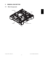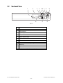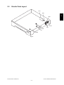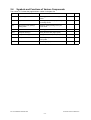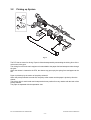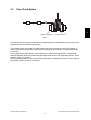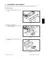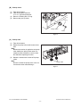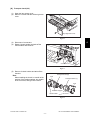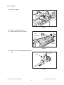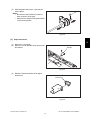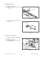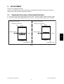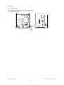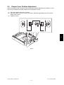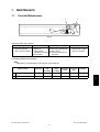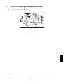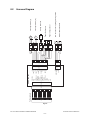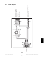
1
SERVICE MANUAL
PAPER FEED UNIT
MY-1027
File No. SME05002800
R05092196900-TTEC
Ver00_2005-12
© 2005 TOSHIBA TEC CORPORATION All rights reserved
Under the copyright laws, this manual cannot be reproduced in any form without prior written permission
of TOSHIBA TEC CORPORATION. No patent liability is assumed, however, with respect to the use of the
information contained herein.
General Precautions for Installation/Servicing/Maintenance
for the MY-1027
The installation and service should be done by a qualified service
technician.
1) When installing the MY-1027 to the Equipment, be sure to follow the instructions described in the
“Unpacking/Set-Up Procedure for the MY-1027” booklet which comes with each unit of the MY-1027.
2) The MY-1027 should be installed by an authorized/qualified person.
3) Before starting installation, servicing or maintenance work, be sure to turn OFF and unplug the
equipment first.
4) When servicing or maintaining the MY-1027, be careful about the rotating or operation sections such
as gears, pulleys, sprockets, cams, belts, etc.
5) When parts are disassembled, reassembly is basically the reverse of disassembly unless otherwise
noted in this manual or other related materials. Be careful not to reassemble small parts such as
screws, washers, pins, E-rings, toothed washers to the wrong places.
6) Basically, the machine should not be operated with any parts removed or disassembled.
7) Delicate parts for preventing safety hazard problems (such as switches, sensors, etc. if any) should
be handled/installed/adjusted correctly.
8) Use suitable measuring instruments and tools.
9) During servicing or maintenance work, be sure to check the serial No. plate and other cautionary
labels (if any) to see if they are clean and firmly fixed. If not, take appropriate actions.
10)The PC board must be stored in an anti-electrostatic bag and handled carefully using a wristband,
because the ICs on it may be damaged due to static electricity. Before using the wrist band, pull out
the power cord plug of the equipment and make sure that there is no uninsulated charged objects in
the vicinity.
11)For the recovery and disposal of used MY-1027, consumable parts and packing materials, follow the
relevant local regulations/rules should be followed.
12)After completing installation, servicing and maintenance of the MY-1027, return the MY-1027 to its
original state, and check operation.
CONTENTS
MY-1027
1. SPECIFICATION ........................................................................................................... 1-1
2. GENERAL DESCRIPTION............................................................................................ 2-1
2.1
2.2
2.3
2.4
2.5
Main Components................................................................................................................ 2-1
Sectional View ..................................................................................................................... 2-2
Electric Parts Layout............................................................................................................ 2-3
Symbols and Functions of Various Components................................................................. 2-4
Diagram of Signal Blocks..................................................................................................... 2-5
3. DESCRIPTION OF OPERATIONS ............................................................................... 3-1
3.1 Outline ................................................................................................................................. 3-1
3.2 Picking up System ............................................................................................................... 3-2
3.3 Paper Feed System ............................................................................................................. 3-3
4. DISASSEMBLY AND ASSEMBLY ............................................................................... 4-1
5. ADJUSTMENT .............................................................................................................. 5-1
5.1 Adjustment Procedure of Horizontal Deviation .................................................................... 5-1
5.2 Drawer Cover Position Adjustment...................................................................................... 5-3
6. TROUBLESHOOTING .................................................................................................. 6-1
7. MAINTENANCE ............................................................................................................ 7-1
7.1 Periodic Maintenance .......................................................................................................... 7-1
8. CIRCUIT DIAGRAM / HARNESS DIAGRAM ............................................................... 8-1
8.1 Assembly Of PC Board........................................................................................................ 8-1
8.2 Harness Diagram................................................................................................................. 8-2
8.3 Circuit Diagram .................................................................................................................... 8-3
December 2005 © TOSHIBA TEC
MY-1027 CONTENTS
1
MY-1027 CONTENTS
December 2005 © TOSHIBA TEC
2
1.
SPECIFICATION
Function:
Paper Size:
Paper Thickness:
Transport speed:
Drawer capacity:
Dimensions:
Weight:
Power supply:
Automatic paper feed single cassette front loading
A3 to B5-R / LD to LT-R
Plain paper 64 to 80 g/m2 (17 to 21 lbs. Bond)
91 mm/sec./ 110 mm/sec (2 speed control)
Paper height 28 mm (Approx. 250 sheets)
530 (W) x 577 (D) x 125 (H) mm (Protrutions excluded)
Approx. 5.0 kg
5 V DC, 24 V DC (Supplied from copier)
December 2005 © TOSHIBA TEC
MY-1027 SPECIFICATION
1-1
1
MY-1027 SPECIFICATION
December 2005 © TOSHIBA TEC
1-2
2.
2.1
GENERAL DESCRIPTION
Main Components
Drawer tray
2
Gear
Drawer
Jam accsess cover
Fig. 2-1
December 2005 © TOSHIBA TEC
MY-1027 GENERAL DESCRIPTION
2-1
2.2
Sectional View
1
2
3
10
4
5 6
11
7
8
9
12
Fig. 2-2
1
Drawer
2
Paper feed unit PC board (PFU board)
3
Pickup solenoid
4
Paper empty sensor
5
Pickup roller
6
Drawer detection switch
7
Paper feed sensor
8
Feed roller
9
Jam accsess cover opening/closing switch
10
Drawer tray
11
Separation craw
12
Transport clutch (High speed / Low speed)
MY-1027 GENERAL DESCRIPTION
December 2005 © TOSHIBA TEC
2-2
2.3
Electric Parts Layout
PFU
SOL
SW1
CLT2
CLT1
S1
S2
SW2
Fig. 2-3
December 2005 © TOSHIBA TEC
MY-1027 GENERAL DESCRIPTION
2-3
2
2.4
Symbols and Functions of Various Components
The column "P-I" shows the page and item number in the parts list.
Symbol
Name
Function
Remarks
S1
Paper empty sensor
Detecting presence/absence of paper in the
drawer
S2
Paper feed sensor
Detecting paper jam and paper transport at
the feeding section
SW1
Jam access cover opening/
closing switch
Detecting opening/closing of the jam
access cover
SW2
Drawer detection switch
Detecting presence/absence of the drawer
CLT1
Transport clutch (H)
Driving the feed roller (High speed)
CLT2
Transport clutch (L)
Driving the feed roller (Low speed)
SOL
Pickup solenoid
Controlling the power transmission of the
pick up roller
PFU
PFU control PC board
Controlling the paper feed unit
MY-1027 GENERAL DESCRIPTION
P-I
December 2005 © TOSHIBA TEC
2-4
2.5
Diagram of Signal Blocks
Equipment
PFU
Transport clutch (High speed) (CLT1)
PFUFEDCLT-H
PFUFEDCLT-L
Driver
Transport clutch (Low speed) (CLT2)
2
Pickup solenoid (SOL)
PFUPSOL
PFUEMPSW
Paper empty sensor (S1)
PFUFEDSW
Paper feed sensor (S2)
Jam accsess cover opening/closing switch (SW1)
PFUSIDECOV
Drawer detection switch (SW2)
PFUCSTSW
DC 24V
DC 5V
PFUCNT
GND
Fig. 2-4
December 2005 © TOSHIBA TEC
MY-1027 GENERAL DESCRIPTION
2-5
MY-1027 GENERAL DESCRIPTION
December 2005 © TOSHIBA TEC
2-6
3.
3.1
DESCRIPTION OF OPERATIONS
Outline
The PFU is an additional paper feed unit and installed under the standard drawer (in the main equipment).
The PFU consists of 1 drawer, 2 sensors, 2 switches, 2 magnetic clutches and 1 solenoid.
3
December 2005 © TOSHIBA TEC
MY-1027 DESCRIPTION OF OPERATIONS
3-1
3.2
Picking up System
1
4
2
3
Fig. 3-1
The PFU has no motor for driving. Paper is fed and transported by transmitting the driving force of the
main motor to the gear.
The driving force from the main equipment is transmitted to the paper feed and transport rollers through
the gear.
When the drawer is inserted to the PFU, the drawer tray goes up by the spring force and paper can be
fed.
Paper is picked up by the motion of the pickup solenoid.
When the pickup solenoid is turned ON, the pickup roller rotates and the paper is picked up from the
drawer.
The pickup roller is semicircular and it stops at the home position for every rotation with the latch of the
pickup solenoid.
The paper is separated with the separation claw.
MY-1027 DESCRIPTION OF OPERATIONS
December 2005 © TOSHIBA TEC
3-2
3.3
Paper Feed System
3
Transport clutch (H)
Transport clutch (L)
Fig. 3-2
The transport clutch (L/H) is turned ON when it transports paper and transmits the driving force from the
equipment to the feed roller through the gear.
The transport clutch (Low speed) is turned ON when the paper is picked up from the PFU drawer or
when the low speed transportation is performed for printing on the equipment. (Transportation speed:
91 mm/sec)
The transport clutch (High speed) is turned ON when the high speed transportation is performed to
transport the paper which has passed through the paper feed sensor to the registration position. (Transportation speed: 110 mm/sec)
High speed transportation is also performed when the paper is transported from the PFP to the registration position. (When the PFP is connected)
December 2005 © TOSHIBA TEC
MY-1027 DESCRIPTION OF OPERATIONS
3-3
MY-1027 DESCRIPTION OF OPERATIONS
December 2005 © TOSHIBA TEC
3-4
4.
DISASSEMBLY AND ASSEMBLY
Be sure to take off the PFU unit from the equipment before assembling/disassembling the unit.
[A] Pickup solenoid
(1)
Remove 3 screws and take off the rear
cover.
Rear cover
Fig. 4-1
(2)
(3)
Disconnect 1 connector.
Remove 1 screw and take off the pickup
solenoid with bracket.
Bracket
Fig. 4-2
(4)
Remove 1 screw and take off the pickup
solenoid.
Pickup solenoid
Fig. 4-3
December 2005 © TOSHIBA TEC
MY-1027 DISASSEMBLY AND ASSEMBLY
4-1
4
[B] Pickup clutch
(1)
(2)
(3)
(4)
Take off the drawer.
Take off the pickup solenoid.
P. 4-1 "[A] Pickup solenoid"
Remove 1 bushing and 1 E-ring.
Remove the pick up clutch.
E-ring
Pickup clutch
Bush
Fig. 4-4
[C] Pickup roller
(1)
(2)
Take off the drawer.
Rotate the pickup roller shaft counter-clockwise.
Note:
Because the tension is applied to the pickup
roller shaft by the pickup clutch when it is
rotated counter-clockwise, be sure to hold
the shaft while replacing the roller.
(3)
Release 2 latches each to take off 2 pickup
rollers.
Note:
Be sure to install the pickup roller in the correct direction when reassembling it.
Pickup roller
Fig. 4-5
MY-1027 DISASSEMBLY AND ASSEMBLY
December 2005 © TOSHIBA TEC
4-2
[D] Transport clutch (H/L)
(1)
(2)
Open the jam access cover.
Remove 1 screw and take off the right rear
cover.
Right rear cover
Fig. 4-6
(3)
(4)
4
Disconnect 2 connectors.
Rotate 2 clutch holders and take off the
clutch holders with clutches.
Clutch holder
Connector
Fig. 4-7
(5)
Remove 2 clutch holders and take off the
clutches.
Note:
When installing the clutch, be careful of the
position of the rotation stopper, pin number
of the connector, and type of the clutch.
Transport clutch (H)
3 pin
Transport clutch (L)
2 pin
Rotation stopper
Clutch holder
Fig. 4-8
December 2005 © TOSHIBA TEC
MY-1027 DISASSEMBLY AND ASSEMBLY
4-3
[E] Feed roller
(1)
Remove 1 spring.
Spring
Fig. 4-9
(2)
(3)
Remove 2 clips and 2 bushes.
Remove the feed roller with gears.
Feed roller
Clip
Clip
Bushing
Bushing
Fig. 4-10
(4)
Remove 1 E-ring. Slide the gear and remove
1 pin.
Pin
E-ring
Fig. 4-11
MY-1027 DISASSEMBLY AND ASSEMBLY
December 2005 © TOSHIBA TEC
4-4
(5)
Slide the gears and remove 1 pin and pull
out the gears.
Notes:
• Be careful of each position (number of
teeth, direction) of the gear.
• Make sure the stopper of the gear bracket
in the correct position.
Pin
2
1
Fig. 4-12
[F] Paper feed sensor
4
(1)
(2)
Disconnect 1 connector.
Remove 1 screw and take off the sensor with
the bracket.
Bracket
Fig. 4-13
(3)
Release 2 latches and take off the paper
feed sensor.
Feed sensor
Fig. 4-14
December 2005 © TOSHIBA TEC
MY-1027 DISASSEMBLY AND ASSEMBLY
4-5
[G] Paper empty sensor
(1)
(2)
Disconnect 1 connector.
Remove 1 screw and take off the sensor with
the bracket.
Bracket
Fig. 4-15
(3)
Release 2 latches and take off the paper
empty sensor.
Paper empty sensor
Fig. 4-16
[H] Jam access cover switch
(1)
(2)
(3)
Remove 1 screw and take off the right rear
cover.
Disconnect 1 connector.
Release 2 latches and take off the jam
access cover switch.
Connector
Jam access cover switch
Fig. 4-17
MY-1027 DISASSEMBLY AND ASSEMBLY
December 2005 © TOSHIBA TEC
4-6
[I]
(1)
(2)
(3)
Drawer detection switch
Take off the drawer.
Disconnect 1 connector.
Release 2 latches and take off the drawer
detection switch.
Drawer detecton switch
Fig. 4-18
[J]
(1)
(2)
(3)
4
PFU control PC board
Take off the rear cover.
Disconnect 3 connectors.
Release 4 lock supports and take off the ADF
board.
Lock support
Connector
PFU Board
Lock support
Fig. 4-19
December 2005 © TOSHIBA TEC
MY-1027 DISASSEMBLY AND ASSEMBLY
4-7
MY-1027 DISASSEMBLY AND ASSEMBLY
December 2005 © TOSHIBA TEC
4-8
5.
ADJUSTMENT
The PFU is not adjusted for itself.
However, if the paper fed from the PFU drawer is misaligned horizontally from the one fed from the
drawer of the main equipment, adjust the deviation.
5.1
Adjustment Procedure of Horizontal Deviation
A: The center of the printed image shifts to the front side. : Move the drawer catcher to the front side.
B: The center of the printed image shifts to the rear side. : Move the drawer catcher to the rear side.
A: Shift to the front side
B: Shift to the rear side
Feeding from equipment
Feeding from equipment
[Rear]
[Rear]
Feeding direction
Feeding direction
Center
Center
5
[Front]
[Front]
Feeding from PFU
Feeding from PFU
Fig. 5-1
December 2005 © TOSHIBA TEC
MY-1027 ADJUSTMENT
5-1
<Procedure>
(1)
(2)
(3)
Loosen 1 screw.
Move the drawer catcher to the front or rear side.
Tighten the 1 screw.
(B)
(A)
Fig. 5-2
MY-1027 ADJUSTMENT
December 2005 © TOSHIBA TEC
5-2
5.2
Drawer Cover Position Adjustment
Adjust the drawer position as follows when the sideways deviation adjustment in Chapter 5.1 is performed or the misalignment with the drawer of the equipment is found.
(1)
(2)
(3)
Pull out the drawer and loosen 3 screws.
Move the drawer cover to the front or rear side to adjust the gap between the PFU and the
drawer cover evenly.
Tighten 3 screws.
5
Fig. 5-3
December 2005 © TOSHIBA TEC
MY-1027 ADJUSTMENT
5-3
MY-1027 ADJUSTMENT
December 2005 © TOSHIBA TEC
5-4
6.
TROUBLESHOOTING
1. Paper is not picked up.
Is there any deformation or wear of the pickup roller?
È
ÆYES
Replace the pickup roller.
NO
Does the pickup roller rotate? (Output check: Perform 101 before performing 202)
È
ÆNO
Replace the pickup solenoid or fix the breakage of the drive system.
YES
Is the lift-up mechanism of the drawer normal?
È
ÆNO
Fix the lift-up mechanism.
YES
Is the paper empty sensor normal? (Input check: [Interrupt] button turned OFF, 6, LED5)
È
ÆNO
Replace the paper empty sensor.
YES
Fan the paper and load it again.
2. Multiple sheets of paper are fed in one go.
6
Is the paper damp?
È
ÆYES
Replace the paper.
NO
Is the paper separation claw deformed?
È
ÆYES
Fix or replace the paper separation claw.
NO
Fan the paper and load it again.
December 2005 © TOSHIBA TEC
MY-1027 TROUBLESHOOTING
6-1
3. Paper is picked up, but is not fed to the equipment.
Does the feed roller rotate? (Output check: Perform 101 before performing 202)
È
ÆNO
Replace the drive gear or transport clutch (L).
YES
Is the feed sensor normal? (Input check: [Interrupt] button turned OFF, 7, LED5)
È
ÆNO
Replace the paper feed sensor.
YES
Check the feed roller and replace it if it is worn or deformed.
4. Paper skews or deviates sideways.
Is the paper correctly set?
È
ÆNO
Fan the paper and load it again.
YES
Is the width of the paper guide properly adjusted?
È
ÆNO
Adjust the width of the guide to that of the paper.
YES
Check if the marks of the right and left scales for the drawer cover position are on the same
number. Perform sideways deviation adjustment if necessary.
5. The PFU does not operate.
Check if the connection with the equipment is normal. (Input check: [Interrupt] button turned
OFF, 8, LED4)
È
ÆNO
Connect the connector correctly or replace the harnesses.
YES
Replace the PFU board.
MY-1027 TROUBLESHOOTING
December 2005 © TOSHIBA TEC
6-2
7.
7.1
MAINTENANCE
Periodic Maintenance
2
1
Fig. 7-1
Symbols used in the checklist
Cleaning
Lubrication/Coating
L: Launa 40
A: Clean with alcohol
SI: Silicon oil
B: Clean with soft pad,
cloth or vacuum cleaner W: White grease
(Molykote X5-6020)
AV:Alvania No.2
Replacement
The number of sheets consumed before replacement
(Value x 1,000).
R: Replace if deformed or
damaged
Operation check
O: After cleaning or
replacement, confirm
there is no problem
Preventive Maintenance Checklist
Note:
Page-Item (P-I) is described in the column of the Parts list.
Item to check
Cleaning
1
Pickup roller
A
2
Feed roller
A
Lubrication/
Coating
Replacement
(x1,000)
90
Operation
check
Parts list
(P-I)
Remarks
3-12
3-16
7
December 2005 © TOSHIBA TEC
MY-1027 MAINTENANCE
7-1
MY-1027 MAINTENANCE
December 2005 © TOSHIBA TEC
7-2
8.
8.1
CIRCUIT DIAGRAM / HARNESS DIAGRAM
Assembly Of PC Board
Fig. 8-1
8
December 2005 © TOSHIBA TEC
MY-1027 CIRCUIT DIAGRAM / HARNESS DIAGRAM
8-1
J4
1
2
3
4
5
6
7
8
9
10
11
12
13
14
15
To Equipment
15
14
13
12
11
10
9
8
7
6
5
4
3
2
1
J221
CN221
PSOL-0
FEDCLT-H0
+24V
+24V
PG
PG
PFUCNT-0
SG
+5V
SIDECOV-0
FEDSW-0
CSTSW-0
EMP-0
NEAREMP-0
FEDCLT-L0
MY-1027 CIRCUIT DIAGRAM / HARNESS DIAGRAM
8-2
SG
CSTSW
CN223
+24V
FEDCLT-L
+24V
FEDCLT-H
+24V
PICKSOL CN222
SG
FEDSNR
+5V
SG
EMPSNR
+5V
SG
SIDECOVSW
PWA-F-PFU-641
J223
J222
1
2
3
4
1
2
3
4
5
6
7
8
9
10
11
12
2
1
J536
J539
J537
3
2
1
2
1
J540
J538
J542
J543
3
2
1
2
1
3
2
1
2
1
S1
S2
SW2
SW1
2
1
3
2
1
2
1
Pickup solenoid
Transport clutch (H)
Transport clutch (L)
Drawer detection switch
Jam access cover opening/closing switch
Paper empty sensor
Paper feed sensor
SOL
CLT1
CLT2
8.2
Harness Diagram
Fig. 8-2
December 2005 © TOSHIBA TEC
To Equipment
Jam accsess cover opening/closing switch
Drawer detection switch
Paper empty sensor
Paper feed sensor
Transport clutch (Low speed)
Transport clutch (High speed)
Pickup solenoid
8.3
Circuit Diagram
8
Fig. 8-3
December 2005 © TOSHIBA TEC
MY-1027 CIRCUIT DIAGRAM / HARNESS DIAGRAM
8-3
MY-1027 CIRCUIT DIAGRAM / HARNESS DIAGRAM
December 2005 © TOSHIBA TEC
8-4