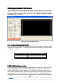
1
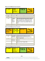
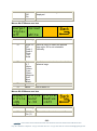
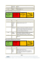
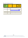
eyeheight SA-3G SD/HD/3G safe-area generator user manual User Manual Versions Versions Changes Date S/W Ver 0.02 Provisional Version 27/02/08 1.00 First Released Version 21/04/08 1.6 1.10 Moveable user Box and Onscreen aspect ratio calculation added 17/06/09 2.10 1.20 Changed Title, Expanded section on cage uploader 28/9/09 2.11 1.30 Change to new single piece 3G compatible hardware 04/06/10 2.11 1.40 Change to SA-3G on screen menu operation 02/04/12 3.00 1.50 Change to new SD/HD/3G version 05/07/12 4.00 -2eyeheight Unit 34 Park House Watford Business Park Greenhill Crescent Watford Herts GB WD18 8PH Reg. No. 2855535 Telephone: +44 (0) 1923 256 000 Fax: +44 (0) 1923 256 100 email: [email protected] Table of Contents 1 System Overview ............................................................................................... 6 1.1 The SA-3G product ................................................................................. 6 1.2 Associated Equipment for the SA-3G ..................................................... 6 2 Installation. ......................................................................................................... 7 3 Operation ........................................................................................................... 8 3.1 General flexiPanel control ....................................................................... 8 3.1.1 Device buttons ..................................................................................... 8 3.1.2 Menu navigation................................................................................... 8 3.1.3 Parameter adjustment of a green menu ............................................... 9 3.1.4 Parameter adjustment of a red menu................................................... 9 3.1.5 Information display ............................................................................... 9 3.2 Primary safe-area generator control and OSD (On-Screen Menu) ......... 9 3.2.1 Safe Area Generator ON/OFF ............................................................. 9 3.2.2 Selecting a User Preset ..................................................................... 10 3.2.3 Selecting a Preset Safe Area ............................................................. 10 3.2.4 Saving a new user preset. ................................................................. 11 3.2.5 Hiding safe areas in the safe area On Screen Menu. ........................ 12 3.3 Special purpose cursor generator control ............................................. 13 3.3.1 Text height measurement .................................................................. 13 3.3.2 User Box ............................................................................................ 13 3.3.3 Strobe ................................................................................................ 14 3.3.4 Cursor ................................................................................................ 14 3.3.5 Circle.................................................................................................. 14 3.4 GPI/Tally Set-up.................................................................................... 15 3.4.1 On-Board GPI’s.................................................................................. 15 3.4.2 On-Board Tally ................................................................................... 15 3.4.3 Configuring tallies on the etherBox. ................................................... 15 4 The SA-3G Menu Set. ...................................................................................... 16 5 Technical Appendix .......................................................................................... 30 5.1 GPI/Tally/RS232 technical information. ................................................ 30 5.1.1 GPI Inputs. ......................................................................................... 30 -3eyeheight Unit 34 Park House Watford Business Park Greenhill Crescent Watford Herts GB WD18 8PH Reg. No. 2855535 Telephone: +44 (0) 1923 256 000 Fax: +44 (0) 1923 256 100 email: [email protected] 5.1.2 Tally Output. ...................................................................................... 31 5.1.3 RS232 Interface. ................................................................................ 31 5.2 CageUploader Software ........................................................................ 32 5.2.1 Connecting CageUploader ................................................................. 32 5.2.2 Defining New cursors. ........................................................................ 32 5.2.3 Defining New video standards. .......................................................... 33 5.2.4 Upload/Download/Saving/Loading ..................................................... 33 5.3 Technical Specification. ........................................................................ 33 -4eyeheight Unit 34 Park House Watford Business Park Greenhill Crescent Watford Herts GB WD18 8PH Reg. No. 2855535 Telephone: +44 (0) 1923 256 000 Fax: +44 (0) 1923 256 100 email: [email protected] Table of Figures Figure 1-1 - Front view of etherBox (FB-9E) fitted with FF-9 blank panel ............ 6 Figure 1-2 FP-9 flexiPanel can be fitted on the FB-9E or remotely using an RR-9 kit. .................................................................................................................. 6 Figure 2-1 Connections to the SA-3G ................................................................... 7 Figure 3-1 flexiPanel (FP-9) controls.................................................................... 8 Figure 3-2 Types of menus showing their characteristic colours ........................... 8 3-3 OSD User Preset Selection ........................................................................... 10 3-4 OSD Preset Cursor Selection.................................................................... 1098 3-5 Saving the User Preset. ................................................................................ 11 3-6 Naming the User Preset ................................................................................ 12 Figure 5-1 Typical GPI Input ............................................................................... 30 Figure 5-2 Tally Output........................................................................................ 31 Figure 5-3 Tally interface to relay. ....................................................................... 31 Figure 5-4 Cage Uploader Software .................................................................... 32 -5eyeheight Unit 34 Park House Watford Business Park Greenhill Crescent Watford Herts GB WD18 8PH Reg. No. 2855535 Telephone: +44 (0) 1923 256 000 Fax: +44 (0) 1923 256 100 email: [email protected] 1 System Overview 1.1 The SA-3G product The SA-3G is a safe area generator designed to operate in SD, HD and 3G Formats. The unit processes all SD and HD formats and 3G 1080p 50/60 level A. The SA-3G can display up to 4 simultaneous safe-areas/cursors and each safearea/cursor has independent controls for style, colour and opacity. All safe-areas have independently controllable centre markers. A further graphic generator will generate circles. 1.2 Associated Equipment for the SA-3G The SA-3G processing card requires the following in order to set up and operate the unit. 1. An etherBox chassis (FB-9E). Up to six SA-3G units and be installed in one chassis. 2. A flexiPanel control surface such as an FP-9 or an FP-10. Figure 1-1 - Front view of etherBox (FB-9E) fitted with FF-9 blank panel Figure 1-2 FP-9 flexiPanel can be fitted on the FB-9E or remotely using an RR-9 kit. -6eyeheight Unit 34 Park House Watford Business Park Greenhill Crescent Watford Herts GB WD18 8PH Reg. No. 2855535 Telephone: +44 (0) 1923 256 000 Fax: +44 (0) 1923 256 100 email: [email protected] 2 Installation. This unit requires HD-SDI , SD-SDI or 3G digital video connections to the BNC connectors. Optionally RS232, GPI’s and a Tally may also be connected normally using CAT5e cable. The user should refer to the etherBox user manual for installation of the SA-3G into a chassis and connection of flexiPanels (FP-9). This will also describe the process of acquiring a processing card (in this case the SA3G) by the flexiPanel which is necessary to access the menu structure within the SA-3G. Figure 2-1 Connections to the SA-3G See Section 5.1 for details of the GPI/Tally/RS-232 pinout. -7eyeheight Unit 34 Park House Watford Business Park Greenhill Crescent Watford Herts GB WD18 8PH Reg. No. 2855535 Telephone: +44 (0) 1923 256 000 Fax: +44 (0) 1923 256 100 email: [email protected] 3 Operation All geNETics products are controlled using a generic menu system. This generic menu system is operated from a generic panel (flexiPanel FP-9 or FP-10). An FP-9 is shown below (An FP-10 has the same controls in a different layout style). For information about acquiring processor cards for control on a flexiPanel see the etherBox manual section 4. The SA-3G card differs slightly from the generic operation in order to allow for simple use of the OSD menus however. These differences are explained in section Primary safe-area generator control below. 3.1 General flexiPanel control Figure 3-1 flexiPanel (FP-9) controls. 3.1.1 Device buttons There are 8 grey device buttons. These switch between the currently selected processing cards installed in the etherBox. It is also possible to select cards in another chassis if the I-Bus is connected to the other chassis. 3.1.2 Menu navigation There are two ways to navigate from menu to menu. 1. Using the NEXT ane PREV buttons. These are for “Flat” menu structures. The NEXT and PREV LEDS will flash while further menus are available. 2. Using a GOTO ANOTHER MENU LCD button (as below coloured orange). This is more common and will take you straight to a relevant set of menus. Examples are the Play and UTILS menu’s shown on Figure 8. GOTO ANOTHER MENU SINGLE PARAMETER ADJUSTMENT DOUBLE OR TRIPLE PARAMETER ADJUSTMENT INFORMATION DISPLAY Figure 3-2 Types of menus showing their characteristic colours -8eyeheight Unit 34 Park House Watford Business Park Greenhill Crescent Watford Herts GB WD18 8PH Reg. No. 2855535 Telephone: +44 (0) 1923 256 000 Fax: +44 (0) 1923 256 100 email: [email protected] 3.1.3 Parameter adjustment of a green menu A green menu is one in which there is only one adjustable parameter. There are two ways to adjust the parameter in a green menu. 1. Press the green LCD button. This will increment the value in that window. This is most frequently done when the menu parameter is Textural for example switching a parameter between ON and OFF. In this case a button press is most natural. 2. Use the Rotary digipot (A,B,C or D) to adjust the parameter in the respective LCD window (A,B,C or D). The direction and speed of rotation enable numeric values to be set easily. 3.1.4 Parameter adjustment of a red menu A red menu is one in which there is two or three adjustable parameters. In this case it is necessary to first select the menu by pressing the red button. When the red button is pressed it will turn green and either two or three of the rotary digipot LEDS will flash indicating that the respective rotary digipot will operate the respective parameter. 3.1.5 Information display A Yellow menu (Which on most panels does look a light orange!) is one in which only information is displayed. An example of this is the software version display. 3.2 Primary safe-area generator control and OSD (On-Screen Menu) The top level menu shown below gives direct access to the selection menus for the three primary safe-area generators. USER MEMORY 1 * A LEGACY SAFE ACTN * B C D 3.2.1 Safe Area Generator ON/OFF The top level menus are in LCD windows A,B,C and D. These correspond to the four digipots labelled A,B,C and D on the FP-9 panel. If the user presses LCD A the unit toggles between hiding and showing the cursors (SAG ON and SAG OFF) -9eyeheight Unit 34 Park House Watford Business Park Greenhill Crescent Watford Herts GB WD18 8PH Reg. No. 2855535 Telephone: +44 (0) 1923 256 000 Fax: +44 (0) 1923 256 100 email: [email protected] 3.2.2 Selecting a User Preset Moving Digipot “B” will activate the OSD showing all 16 user presets on the display. This is shown below. 3-3 OSD User Preset Selection To select a user preset move the on-screen cursor to the appropriate memory and the PUSH the digipot in until it clicks. A star (*) will be shown beside the selected memory 3.2.3 Selecting a Preset Safe Area To select a preset safe area, move digipot “C”. This will activate the OSD showing all the safe areas appropriate for the input line standard. These will depend upon the line standard that is currently input.Only 20 cursors are shown on each form. If there are more cursors simply scroll down and more will appear. An example of this is shown below. 3-4 OSD Preset Cursor Selection - 10 eyeheight Unit 34 Park House Watford Business Park Greenhill Crescent Watford Herts GB WD18 8PH Reg. No. 2855535 Telephone: +44 (0) 1923 256 000 Fax: +44 (0) 1923 256 100 email: [email protected] To select a safe area, move the “on-screen cursor” to the appropriate safe area and the PUSH the digipot in until it clicks. This will then activate the selected safe area and display it on screen. A star (*) will be shown beside the selected safe area. Up to 3 different safe areas can be selected on the screen. Pressing the digipot “C” on a cursor already selected will de-select that cursor. Trying to select a 4th cursor (when 3 have already been selected) will deselect the cursor that was last selected and select the new one. The user can still select another cursor feature by pressing LCD button D and selecting one of the many Special Screen Utils such as a user box, circle, crosshairs and so on. 3.2.4 Saving a new user preset. Once the user has selected a cursor or set of cursors (and possibly a special screen utility) this configuration can be stored in a user memory. User memories depend on the line standard of the input signal and there are 16 user memories for each of the four basic line standards (525, 625, 1080, 720). To save a configuration as a user preset, select the memory you wish to store this under by selecting with digipot “B” and then press LCD Button B. The screen will change as below. 3-5 Saving the User Preset. In this case the user will store the current configuration of cursors into the current default named “USER MEM 16 625”. Now using digipot B move the cursor over the “YES” and press the digipot until it clicks. A new screen will appear enabling you to name the preset as below. - 11 eyeheight Unit 34 Park House Watford Business Park Greenhill Crescent Watford Herts GB WD18 8PH Reg. No. 2855535 Telephone: +44 (0) 1923 256 000 Fax: +44 (0) 1923 256 100 email: [email protected] 3-6 Naming the User Preset To name the user preset use digipot “B” to move the roving cursor over any character on the two top lines of this form and Press Digipot “B”. This will enter a character into the user name under the static cursor. To move the static cursor simply move the roving cursor over the NAME section of the form and Press Digipot “B”. Once the user has named the preset select the roving cursor over the text END in the form and press digipot “B”. 3.2.5 Hiding safe areas in the safe area On Screen Menu. Because of the quantity of the cursors in some line standards (for example in 625 there are, at the time of writing, 42 cursors that can be selected). It is often desirable to hide cursors which the user either never or very rarely uses. To do this Press the following sequence from the top menu on the LCD buttons. Special Screen UtilsMOREMOREMORESetup OSD. Legacy Safe Actn X A B C D The above menu should be displayed along with an on screen display. In this case now to HIDE a cursor, select the cursor using digipot “A” and the Press digipot “A” until it clicks. An “X” - 12 eyeheight Unit 34 Park House Watford Business Park Greenhill Crescent Watford Herts GB WD18 8PH Reg. No. 2855535 Telephone: +44 (0) 1923 256 000 Fax: +44 (0) 1923 256 100 email: [email protected] 3.3 Special purpose cursor generator control The special purpose cursor provides real-time user configurable safe-area, text height measurement, pixel strobe, cursor functionality and onscreen aspect ratio information. The special purpose cursor layer is composited on top of the primary safe-area layers. 3.3.1 Text height measurement TEXT HEIGHT OFF Adjust A=100 B=120 TEXT HEIGHT = 20 L Pressing the first button or adjusting digi-pot 1 will toggle the visibility of the text height measurement cursor. If another special purpose cursor is being displayed it will be removed. The text height measurement cursor displays a horizontal opaque stripe across the full width of the image. The “Adjust” menu is red to indicate that it is an unopened nested menu. Pressing the “Adjust” menu will open it (the “Adjust” menu will turn green and the first “TEXT HEIGHT” menu will go red) The A value can no be adjusted using the first digi-pot and the B value can be adjusted using the second. Align the top and bottom of the opaque band with the top and bottom of the text to be measured and read of the text height in lines from the third menu. The “Adjust” menu can be closed by pressing any of the menu buttons. 3.3.2 User Box Box On S1.333 W1.777 Box Size Box Left =199 Box Right =23 Box Offset V=123 Box Offset H=456 Box Pos Box Top =44 Box Bottom =98 - 13 eyeheight Unit 34 Park House Watford Business Park Greenhill Crescent Watford Herts GB WD18 8PH Reg. No. 2855535 Telephone: +44 (0) 1923 256 000 Fax: +44 (0) 1923 256 100 email: [email protected] Pressing the first menu button or adjusting digi-pot 1 will toggle the user box display through Off, On and On+ which displays the user box and its centre marker. If another special purpose cursor is in use it will be removed. The W and S values indicate the aspect ratio of the user box when viewed in standard aspect ratio (4:3) and widescreen aspect ratio (16:9). For HD signals only the W value is active. The position and size of the user box can be adjusted by accessing the box size and box pos menus. 3.3.3 Strobe LinPix STROBE OFF L=250 P=300 Line Pixel Pressing the first menu button or adjusting digi-pot 1 will toggle the strobe on and off. If another special purpose cursor is being displayed it will be removed. The selected line and pixel can be adjusted using digi-pots 2 and 3. 3.3.4 Cursor CURSOR IS OFF Adjust H=100 V=120 Aspect S1.000 W1.333 Pressing the first menu button or adjusting digi-pot 1 will toggle the cursor on and off. If another special purpose cursor is being displayed it will be removed. The width and height of the cursor can be adjusted by opening the “Adjust” menu and using digi-pot 1 and 2. The W and S values indicate the aspect ratio of the user box when viewed in standard aspect ratio (4:3) and widescreen aspect ratio (16:9). For HD signals only the W value is active. 3.3.5 Circle Aspect Circle =ON Off Circle H=12 V-34 Circle Radius =123 This will operate the circle generator. These menus enable the circle to be switched on and off. The position can be adjusted by the Circle H & V menus and the radius by the Circle Radius menu. - 14 eyeheight Unit 34 Park House Watford Business Park Greenhill Crescent Watford Herts GB WD18 8PH Reg. No. 2855535 Telephone: +44 (0) 1923 256 000 Fax: +44 (0) 1923 256 100 email: [email protected] 3.4 GPI/Tally Set-up. 3.4.1 On-Board GPI’s The SA-3G is a geNETics product. The geNETics system uses generic Input/Output cards which have 3 GPI’s and one Tally output. These have been used in this system as opportunistic GPI’s which may be of use to the user. They do not provide a comprehensive GPI control but may be used as part of a GPI solution in conjunction with the GPI’s on the etherBox. The operation of the two GPI’s used is explained in the table below. Table 1 - On-Board GPI settings GPI1 GPI2 GPI3 Effect OFF 1 1 1 The GPI’s have no effect Master Hide 0 1 1 All cages will be hidden. Master Show 1 0 1 Selected cages will be displayed. 0=Short to ground or logic 0V, 1=Pulled up internally or logic +3+12V 3.4.2 On-Board Tally The single tally output has two modes: 1. Indicate that one or more cages are being displayed. 2. Indicate that no cages are being displayed.. The operation of these is explained in the table below. Table 2 - On-Board Tally settings. Tally State Meaning ON 0 A cage is being displayed OFF 1 No cages are being displayed 0=Transistor ON, shorting to ground, 1=Transistor OFF, open. 3.4.3 Configuring tallies on the etherBox. The SA-3G can also make use of the three configurable tallies on the etherBox chassis. The etherBox chassis has three usable tallies. These are 11,12 and 13. Set up these menus for the box number and tally number for channel A and channel B. If you do not wish to use a tally set the box number to 0. Refer to the etherBox man - 15 eyeheight Unit 34 Park House Watford Business Park Greenhill Crescent Watford Herts GB WD18 8PH Reg. No. 2855535 Telephone: +44 (0) 1923 256 000 Fax: +44 (0) 1923 256 100 email: [email protected] 4 The SA-3G Menu Set. The following set of menus defines the operational controls of the SA-3G. Menus 00-03 Top Level Menus USER MEMORY 1 * Menu Num. LEGACY SAFE ACTN * Heading Function 0 On/Off This setting switches the cursor display on and off. 1 Select User Memories This action is explained in detail in section Primary safe-area generator control and OSD (On-Screen Menu) 2 Cursor Selection This action is explained in detail in section Primary safe-area generator control and OSD (On-Screen Menu) 3 Special Screen Utils Press this button to take you to the menu 04. This is where all the other cursor utilities reside. Pressing the “NEXT” button while the Top Level Menus are displayed will take you to menus 04-07. Menus 04-07 Menus Menu Num. 4 Heading Box Function Press this button to take you to the User Box menus (User definable cage) - 16 - eyeheight Unit 34 Park House Watford Business Park Greenhill Crescent Watford Herts GB WD18 8PH Reg. No. 2855535 Telephone: +44 (0) 1923 256 000 Fax: +44 (0) 1923 256 100 email: [email protected] (Go To Menu 96). 5 Strobe Press this button to take you to the Strobe menus (Go To Menu 92). 6 More Takes you to menu 8 7 Back Back to top menu Menus 08-11 Menus Cage Menu Num. 8 Heading Function Cross Hair Text Height This takes you to the centralised dual cross hair system. (menu 88) This takes you to the text height measurement system (menu 84) 6 More Takes you to menu 12 7 Back Back to menu 4 9 Menus 12-15 Menus Cage 1 CIRCLE Menu Num. Heading 12 13 Circle Setup 14 OSD Setup Function Sends you to the circle utility (Menu 80) Sends you to the general setup utility (Menu 16) Sends you to the OSD setup utility for hiding cursors. - 17 - eyeheight Unit 34 Park House Watford Business Park Greenhill Crescent Watford Herts GB WD18 8PH Reg. No. 2855535 Telephone: +44 (0) 1923 256 000 Fax: +44 (0) 1923 256 100 email: [email protected] 15 Back Press this button to take you back to menu 8. Menus 16-19 Menus Cage 2 Menu Num. Heading 16 System 17 18 Cursor Style Box Setup 19 Back Function This takes you to further system menus. (menu 20) This takes you to the cursor style setup menus. (menu 60) This takes you to the user box configuration menus. (menu 56) Press this button to take you back to Menu 12 Menus 20-23 Menus Cage 2 Menu Num. Heading 20 Tally 21 Reset/Upgrade 22 Input Function This will take you to the Tally setup menu (Menu 24) This will take you to the Rest and software upgrade system menus. (Menu 36) This takes you to the input type selection. (Menu 48) - 18 eyeheight Unit 34 Park House Watford Business Park Greenhill Crescent Watford Herts GB WD18 8PH Reg. No. 2855535 Telephone: +44 (0) 1923 256 000 Fax: +44 (0) 1923 256 100 email: [email protected] 23 Back Press this button to take you back to Menu 16 Menus 24-27 Menus Cage 3 CgeTal Box=0 Tal=4 Menu Num. 24 Heading Function Cage Tally Box 0-16 Tally 0-99 If a cage is displayed a tally will be set. This menu allows you to select the Box and the tally Number that will indicate this. 25 26 27 Back Press this button to take you back to Menu 20 Menus 28-31 Menus Cage 3 ReBoot This Unit FACTRY RESET! !!!!!! Menu Num. Heading Function 28 Reboot this unit This applies a warm restart to the unit. It is the software equivalent of recycling the power. 29 Factory Reset Pressing this will take you to the Factory Reset Last Chance menu. (Go To Menu 44). BACK Go to Menu 36 30 31 - 19 eyeheight Unit 34 Park House Watford Business Park Greenhill Crescent Watford Herts GB WD18 8PH Reg. No. 2855535 Telephone: +44 (0) 1923 256 000 Fax: +44 (0) 1923 256 100 email: [email protected] Menus 32-35 Menus User Controls. START? Menu Num. 32 33 34 35 ARE-> YOU-> SURE-> Heading ------YES, I want to do a factory reset! BACK YES Function ------This will Start a factory Reset of the unit. This will Wipe ALL Cages and Settings that may have been previously set-up. Only do this if you are setting up from scratch, or there is a problem with your unit. Go To Menus 28 Menus 36-39 Menus User Controls UPGRDE SOFTWR NOW! SA-3G 170609 V2.10 Menu Num. 36 Heading Upgrade Software 37 38 Software Version Resets 39 BACK RESETS Function Pressing this will take you to the Software Upgrade last chance menu. (Go To Menu 40). This window displays the software version. Pressing this will take you to the Reset Options. (Go To Menu 28). Go to Menu 20 Menus 40-43 Menus User Controls START? ARE-> YOU-> SURE-> YES - 20 - eyeheight Unit 34 Park House Watford Business Park Greenhill Crescent Watford Herts GB WD18 8PH Reg. No. 2855535 Telephone: +44 (0) 1923 256 000 Fax: +44 (0) 1923 256 100 email: [email protected] Menu Num. 40 41 42 43 Heading ------YES, I want to start a software upgrade BACK Function ------This will Start a software upgrade of the unit. You will need to follow the instructions in the etherbox (FB-9E) manual or the “Flasher User Manual” to correctly perform this procedure. This will Wipe ALL Logos and Settings that may have been previously set-up. The unit MUST be installed in an FB-9E to perform an upgrade. Go to Menu 36 Menus 48-51 Menus Input Status Mode = SMPTE 352 Link = Single Menu Num. Heading 48 Mode 01 SMPTE 352 49 MANUAL Link If in MANUAL mode 0-1 Single Dual 50 Resolution 51 Back Resltn H=1920 V=1080 next → *BACK* Function This Menu allows you to select whether Link, Colour Mode, Bit Depth and Dynamic Range will be interpreted from the SMPTE 352 packet or set manually by the operator. (NOT ADJUSTABLE IN SINGLE LINK) This menu allows you to select Single or Dual Link Mode if Menu 60 is set to MANUAL. Will indicate the link mode if SMPTE 352 packets are being received. (NOT ADJUSTABLE IN SINGLE LINK) This menu displays the Horizontal and Vertical resolution of the detected video standard. Press this button to take you back to Menus 04-07. Press the “NEXT” button to take you to Menu 20 - 21 eyeheight Unit 34 Park House Watford Business Park Greenhill Crescent Watford Herts GB WD18 8PH Reg. No. 2855535 Telephone: +44 (0) 1923 256 000 Fax: +44 (0) 1923 256 100 email: [email protected] Menus 56-59 On-Screen Text setup for Aspect Ratio User Box Display Onscrn Text= On Menu Num. 56 57 58 59 Aspect Ratio= 9 Heading Function Onscreen Text 0–1 Off On If the user box is on, this menu allows the text size to be altered. Denominator 1 - 15 Back If the user box is on, this menu allows the denominator to be chosen Go to Menu 16. Menus 60-63 Cursor Type Parameters (Colour/Style) Menu Num. Heading 63 1st Cursor 64 2nd Cursor 65 3rd Cursor 66 User Box Function This takes you to the parameters for the first cursor. (menu 64) This takes you to the parameters for the second cursor. (menu 68) This takes you to the parameters for the third cursor. (menu 72) This takes you to the parameters for the user box. (menu 76) - 22 eyeheight Unit 34 Park House Watford Business Park Greenhill Crescent Watford Herts GB WD18 8PH Reg. No. 2855535 Telephone: +44 (0) 1923 256 000 Fax: +44 (0) 1923 256 100 email: [email protected] Menus 64-67 Menus Cage 1 Cursor Style= Off Colour Centre White Off Menu Num. Heading Function 64 Style 0-5 Off Dash 1 Dash 2 Thick Thin Solid Use this menu to select the desired cage style. Off is not selectable manually. 65 Colour 0-7 White Yellow Cyan Green Magenta Red Blue Black Centre 0-1 Off On Back Use this menu to select a colour for the selected cage. 66 67 Use this menu to select whether the centre marker of the cage is to be displayed. Go to Menu 60. Menus 68-71 Menus Cage 2 Cursor Style= Off Colour Centre White Off Menu Num. Heading Function 68 Style 0-5 Off Dash 1 Dash 2 Thick Use this menu to select the desired cage style. Off is not selectable manually. - 23 eyeheight Unit 34 Park House Watford Business Park Greenhill Crescent Watford Herts GB WD18 8PH Reg. No. 2855535 Telephone: +44 (0) 1923 256 000 Fax: +44 (0) 1923 256 100 email: [email protected] Thin Solid 69 70 71 Colour 0-7 White Yellow Cyan Green Magenta Red Blue Black Centre 0-1 Off On Back Use this menu to select a colour for the selected cage. Use this menu to select whether the centre marker of the cage is to be displayed. Go to Menu 60. Menus 72-75 Menus Cage 3 Cursor Style= Off Colour Centre White Off Menu Num. Heading Function 72 Style 0-5 Off Dash 1 Dash 2 Thick Thin Solid Use this menu to select the desired cage style. Off is not selectable manually. 73 Colour 0-7 White Yellow Cyan Green Magenta Red Blue Black Centre Use this menu to select a colour for the selected cage. 74 Use this menu to select whether the - 24 - eyeheight Unit 34 Park House Watford Business Park Greenhill Crescent Watford Herts GB WD18 8PH Reg. No. 2855535 Telephone: +44 (0) 1923 256 000 Fax: +44 (0) 1923 256 100 email: [email protected] 75 0-1 Off On Back centre marker of the cage is to be displayed. Go to Menu 60. Menus 64-67 Menus user box Cursor Style= Off Colour White Menu Num. Heading Function 76 Style 0-5 Off Dash 1 Dash 2 Thick Thin Solid Use this menu to select the desired cage style. Off is not selectable manually. 77 Colour 0-7 White Yellow Cyan Green Magenta Red Blue Black Use this menu to select a colour for the selected cage. Back Go to Menu 60. 78 79 Menus 80-83 Menus user box Aspect Circle =ON Off Menu Num. 80 Circle H=12 V-34 Heading Off (0) On (1) Circle Radius =123 Function This switches the circle on and off - 25 eyeheight Unit 34 Park House Watford Business Park Greenhill Crescent Watford Herts GB WD18 8PH Reg. No. 2855535 Telephone: +44 (0) 1923 256 000 Fax: +44 (0) 1923 256 100 email: [email protected] 81 82 83 H and V position Radius Back Horizontal and vertical position of the circle. Adjust the radius of the circle. Go to Menu 12. Menus 84-87 Menus User Controls TEXT HEIGHT OFF Adjust A=300 B=312 TEXT HEIGHT = 12 L Menu Num. Heading Function 84 Text Height 0-1 OFF ON Text Top / Bottom Use this menu to turn the text height reference lines on or off. 85 86 Text Height 87 Back Use this menu to select the desired position of the top and bottom reference lines. Position the top line to the top of the text to be measured and the bottom line to the bottom of the text. This menu shows the height of the text ( the distance between the top and bottom reference lines) in Video Lines. Press this button to take you back to Menu 8. Menus 88-91 Menus User Controls CURSOR IS OFF Menu Num. 88 Adjust H=30 V=30 Heading Cursor 0-1 OFF ON Function This Menu allows you to select whether Strobe will be off, or on. The strobe can be used to locate the line and pixel position of a position on the screen. - 26 - eyeheight Unit 34 Park House Watford Business Park Greenhill Crescent Watford Herts GB WD18 8PH Reg. No. 2855535 Telephone: +44 (0) 1923 256 000 Fax: +44 (0) 1923 256 100 email: [email protected] 89 Adjust 90 Blank 91 Back This menu allows you to position the line position of the strobe. This menu allows you to position the pixel position of the strobe. Press this button to take you back to Menu 8. Menus 92-95 Menus User Controls LinPix STROBE OFF Menu Num. Line = 250 P=300 Pixel Heading 92 Strobe 0-1 OFF ON 93 Line 94 Pixel 95 Back Function This Menu allows you to select whether Strobe will be off, or on. The strobe can be used to locate the line and pixel position of a position on the screen. This menu allows you to position the line position of the strobe. This menu allows you to position the pixel position of the strobe. Press this button to take you back to Menu 4. Menus 96-99 Menus User Controls Box On S1.333 W1.777 Box Size Box Pos Menu Num. Heading Function 96 97 BoxOff BoxOn BoxOn+ Box Size This menu switches the Box on and off. There is also an option for the box on with a centre cross Go to the Box Size menus (menu 100) 98 Box Go to the Box Position menus (menu - 27 - eyeheight Unit 34 Park House Watford Business Park Greenhill Crescent Watford Herts GB WD18 8PH Reg. No. 2855535 Telephone: +44 (0) 1923 256 000 Fax: +44 (0) 1923 256 100 email: [email protected] 99 Position Back 104) Press this button to take you back to Menu 4. Menus 100-103 Menus User Control. Box Left =199 Menu Num. 100 101 102 103 Box Right =23 Box Top =44 Heading Box Bottom =98 Function Box Left Box Right This is the left box side position Box Top Box Bottom This is the top box side position This is the right box side position This is the bottom box side position Menus 104-107 Menus User Control. Box Offset V=123 Menu Num. 104 105 106 107 Box Offset H=456 Heading Function Box H Offset Box V Offset This is the left box side position Back Go back to menu 96 This is the right box side position - 28 eyeheight Unit 34 Park House Watford Business Park Greenhill Crescent Watford Herts GB WD18 8PH Reg. No. 2855535 Telephone: +44 (0) 1923 256 000 Fax: +44 (0) 1923 256 100 email: [email protected] Menus 108-111 Menus User Control. Legacy Safe Actn X Menu Num. Heading Function 108 Hide List List of hhidden safe areas. See Hiding safe areas in the safe area On Screen Menu. 109 110 111 Back Go back to menu 96 - 29 eyeheight Unit 34 Park House Watford Business Park Greenhill Crescent Watford Herts GB WD18 8PH Reg. No. 2855535 Telephone: +44 (0) 1923 256 000 Fax: +44 (0) 1923 256 100 email: [email protected] 5 Technical Appendix 5.1 GPI/Tally/RS232 technical information. The Processor card has an RJ-45 connector with GPI, Tally and RS232 connections as shown below: 1 GPI-1 White/Orange 2 GPI-2 Orange 3 GPI-3 White/Green 4 GND Blue 5 RS232 TX White/Blue 6 RS232 RX Green 7 Not Used White/Brown 8 Tally (open collector) Brown Table 3 GPI/Tally and RS232 pin-out on RJ-45. 5.1.1 GPI Inputs. Figure 5-1 Typical GPI Input GPI’s are normally activated by a short to ground. The GPI has its own internal pull-up resistor. If the user is interfacing with logic then Vhigh = +12V>Vin>+3V Vlow = +0.3V>Vin>0V - 30 eyeheight Unit 34 Park House Watford Business Park Greenhill Crescent Watford Herts GB WD18 8PH Reg. No. 2855535 Telephone: +44 (0) 1923 256 000 Fax: +44 (0) 1923 256 100 email: [email protected] USER OUTPUUT 5.1.2 Tally Output. R 1 10R TR R TALLY PROCESSOR BC817-16 2 3 330R Figure 5-2 Tally Output The user Tally Output is an open collector transistor. The drain should be <200mA. An electro-mechanical relay can be operated by this as shown in the example below. Figure 5-3 Tally interface to relay. 5.1.3 RS232 Interface. This loosely follows the pin convention of EIA-561 which is a standard for RS232 on an RJ45 cable. Only TX, RX and Signal ground (pin 4) are implemented. For the SA-3G the following RS232 parameters apply: 115Kbaud 8 Bits, no parity 1 Stop bit. - 31 - eyeheight Unit 34 Park House Watford Business Park Greenhill Crescent Watford Herts GB WD18 8PH Reg. No. 2855535 Telephone: +44 (0) 1923 256 000 Fax: +44 (0) 1923 256 100 email: [email protected] 5.2CageUploader Software The CageUploader software allows the editing, loading, capturing, addition and deletion of cages. However, if Factory Reset (menu number 96) is performed any changes will be lost as the default cages (see section Error! Reference source not found.) will be reloaded. Figure 5-4 Cage Uploader Software 5.2.1 Connecting CageUploader You can connect directly to the unit using the RJ-45 connector on the rear of the actual SA-3G card module. A specialised cable will be required. The connections for this are as follows: RJ45 pin number 4 5 6 9W D type (Fem) pin number 5 2 3 5.2.2 Defining New cursors. Once connected using this cable run CageUploader. Under the “ToolsComm Port Settings” menu, select the “SA-3G card” drop down option and select the correct COM PORT for your computer. The NID does not matter. Then under “Edit” select “Add/Edit Cage”. At this point you can use the “cage number” field to step through the current Safe Areas installed. You will see a representation of this appear on the right hand side of the application. You will need to step as far - 32 eyeheight Unit 34 Park House Watford Business Park Greenhill Crescent Watford Herts GB WD18 8PH Reg. No. 2855535 Telephone: +44 (0) 1923 256 000 Fax: +44 (0) 1923 256 100 email: [email protected] as cage 123 to find a “Spare” location to define a new safe area. You next need to select the video standard that the sake area is defined in. You can then name the safe area and define the Pixel and line numbers (in progressive format). 5.2.3 Defining New video standards. The SA-3G unit is ready for emerging line standards and it is possible to define a new line standard if the situation arises. Select “EditAdd/Edit Video Standard”. Scrolling through the standards you will see the ones already defined. Scroll to the next “Blank” to add a new video standard. 5.2.4 Upload/Download/Saving/Loading Under the File menu you can Open either from a computer file or from a device (“device” meaning uploading the current safe areas stored in an SA-3G unit). Similarly you can save the current set of safe areas to a file or to a device (“device” meaning downloading the safe areas to an SA-3G). 5.3 Technical Specification. When in SDI mode: SDI Inputs (270 Mbps, 800mV p-p±10% into 75Ω) 1 Input to SMPTE 259M Link A In, Link B In SDI Outputs (270 Mbps, 800mV p-p±10% into 75Ω) 3 Outputs to SMPTE 259M Out1, Out2, Out3 SDI cable equalisation At least 200m of PSF 1/3 Return loss better than 18dB, 5 MHz – 270 Mhz When in HD-SDI mode: HD-SDI Inputs (1.845 Gbps, 800mV p-p±10% into 75Ω) 1 Input to SMPTE 292M, HD-SDI Outputs (1.485 Gbps, 800mV p-p±10% into 75Ω) 3 Outputs to SMPTE 292M, Link A Out1, Out2, Out3 HD-SDI cable equalisation At least 100m of Belden 1694A When in 3G mode: HD-SDI Inputs (2.99 Gbps, 800mV p-p±10% into 75Ω) 1 Input to SMPTE 425M, HD-SDI Outputs (2.99 Gbps, 800mV p-p±10% into 75Ω) 3 Outputs to SMPTE 425M, Out1, Out2, Out3 - 33 eyeheight Unit 34 Park House Watford Business Park Greenhill Crescent Watford Herts GB WD18 8PH Reg. No. 2855535 Telephone: +44 (0) 1923 256 000 Fax: +44 (0) 1923 256 100 email: [email protected] HD-SDI cable equalisation At least 80m of Belden 1694A General: Ancillary Data Passes all ancillary data in vertical and horizontal blanking except for CRC reclalculation. Control Surfaces Option of local or remote FP-9 control panel. Chassis FB-9E etherBox 1U enclosure Supported Formats 720x576/50i 720x487/60i 720x507/60i 1280x720/23.98p 1280x720/24p 1280x720/25p 1280x720/29.97p 1280x720/30p 1280x720/50p 1280x720/59.94p 1280x720/60p 1920x1080/23.98p 1920x1080/23.98psf 1920x1080/24p 1920x1080/24psf 1920x1080/25p 1920x1080/50i 1920x1080/29.97p 1920x1080/59.94i 1920x1080/30p 1920x1080/60i 1920x8080/50p 1920x8080/60p <10us Delay Power Supply 100-240v AC. Less than 50W power consumption with 6 SA-3G units installed. FB-9E Dimension Width 442mm Height 44mm Depth 300mm Weight <3Kg Temperature <25°C ambient, <55°C internal Humidity Recommended 40 to 55% Limits 20 to 80% - 34 eyeheight Unit 34 Park House Watford Business Park Greenhill Crescent Watford Herts GB WD18 8PH Reg. No. 2855535 Telephone: +44 (0) 1923 256 000 Fax: +44 (0) 1923 256 100 email: [email protected] - 35 eyeheight Unit 34 Park House Watford Business Park Greenhill Crescent Watford Herts GB WD18 8PH Reg. No. 2855535 Telephone: +44 (0) 1923 256 000 Fax: +44 (0) 1923 256 100 email: [email protected]