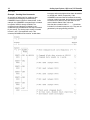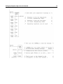
1
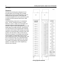
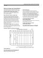
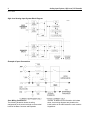
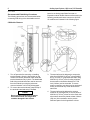
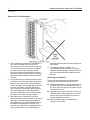
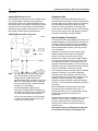
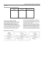
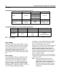
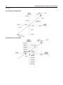
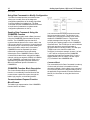
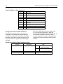
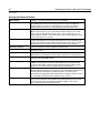
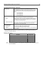
Analog Modules Base Converter Module - IC697ALG230 Current Expander Module - IC697ALG440/IC697ALG444 Voltage Expander Module - IC697ALG441/IC697ALG445 GFK-0385H June 2011 Features Complete Analog subsystem includes Base Converter and Expander modules Base Converter module has eight differential inputs individually configurable for voltage or current Accepts unipolar or bipolar Analog Inputs up to " 10 volts full scale Accepts 4 to 20 milliamp current loop signals Individual user scaling on each input channel on Base Converter module; scaling on a per module basis for Expander modules Fast update rate for Base Converter module Voltage and current Expander modules, each with 16 inputs, provides for additional inputs at a lower cost per point Complete subsystem can accept up to 120 inputs No jumpers or DIP switches to configure Easy configuration with programming software. The ALG444 and ALG445 incorporate the same circuitry as the ALG440 and ALG441 respectively, but also provide gold-plated contacts on the headers and terminal blocks. Hardware Configuration If the ALG444 and ALG445 are not available as selections in the hardware configuration of the programming software, they can be configured by selecting the corresponding module with standard contacts. Functional Compatibility The ALG444 and ALG445 are compatible with all Series 90-70 and RX7i backplanes and expansion racks. For ALG230, ALG440 and ALG441 compatibility, refer to the appropriate system Installation Manual. Base Converter Module 2 Analog Input System, High Level, 16 Channels GFK-0385H Functions The High Level Analog Input subsystem for the Programmable Logic Controller (PLC) accepts analog inputs of up to 10 volts full scale, or 4 to 20 milliamp current loop signals. These inputs are converted to digital form for use by the CPU or other controllers accessing analog inputs via the VME backplane. Converted data is presented as 2’s complement (sign + 15 bits). The basic converter is 14 bits resolution (1 part in 16384); an oversampling and averaging technique further enhances this resolution. Inputs are protected against transient and steady-state overvoltage conditions. Analog inputs use %AI references in the programmable controller. A maximum of 8K words of %AI memory is currently available in the programmable controller. Each input channel uses one word (16 bits) of %AI memory. Field wiring is made to a removable terminal board and the module is mechanically keyed to ensure correct replacement with a similar module type in the field. I/O references are user configurable without the use of jumpers or DIP switches on the module. The system is configured using the programming software. For details, refer to the Programming Software User’s Manual. Analog Expander Module 3 Analog Input System, High Level, 16 Channels GFK-0385H High Level Analog Input System Modules Three module types are included in the High Level Analog Input subsystem: a Base Converter module, a Current Expander module, and a Voltage Expander module. A typical subsystem will use a Base Converter module and (if required) one or more expander modules. Base Converter module, IC697ALG230 This module has eight differential inputs and an expansion port. Each input can be individually configured for either voltage or current. Each of the input channels also has individual user scaling. On-board load resistors are included for normal input current ranges up to 40 mA. If other current ranges or different resolution is required, external resistors may be used. Standard system configurations for 10 volts and 4 to 20 mA are available. These, and other lower input ranges, can be scaled to engineering units with the user scaling feature. Example of High Level Analog Input System System Operation The following illustration is a block diagram of the High Level Analog Input system followed by an example of typical input connections. Expander Modules Up to seven Expander modules can be daisy chained off the Base Converter module to increase the number of inputs of the total subsystem up to a maximum of 120. The Base Converter module accepts any mix of the two Expander module types. A common user scaling factor applies to all inputs on each Expander module; however each Expander module may be individually scaled as required. Current Input Expander module, IC697ALG440/ALG444 The Current Expander module has 16 current inputs each accepting up to 20 mA. Voltage Input Expander module, IC697ALG441/ALG445 The Voltage Expander module has 16 differential voltage inputs each accepting up to 10V signals. 4 Analog Input System, High Level, 16 Channels GFK-0385H High Level Analog Input System Block Diagram Example of Input Connections User Wiring Connections The following illustration shows the wiring assignments for the screw terminals on the terminal board of the Base Converter and Expander modules. In addition to the information in this data sheet, circuit wiring diagrams are printed on the inside surface of the label inserted in each module’s hinged door. 5 Analog Input System, High Level, 16 Channels GFK-0385H Field Wiring Connections to I/O Terminal Boards (Base Converter IC697ALG230 Base Converter IC697ALG440/ALG444 Current Expander IC697ALG441/ALG445 Voltage Expander Jumper [I] connects an internal 250-ohm load for current inputs: leave off for voltage inputs (base converter only). Ground (GND) is chassis ground. Common (COM) is analog common. + and – show polarity for differential inputs referenced to COM. Pins 35 through 40 form the analog expansion bus. 6 Analog Input System, High Level, 16 Channels GFK-0385H Recommended Field Wiring Procedures The following procedures are recommended when connecting field wiring to the detachable terminal board on an Analog Input Base Converter or Expander module. Module features referenced in the following procedures that are common to all IC697 I/O modules are illustrated in the following figure. I/O Module Features 1. Turn off power before removing or installing terminal boards. Open the hinged door on the module to access a jackscrew, which holds the terminal board securely in place. The detachable field wiring terminal board can now be removed from the module by turning the jackscrew counter-clockwise until it is fully disengaged. 2. To remove the terminal board, grasp the top of the terminal board and swing it outward. Caution Do not use the hinged door to remove the terminal board. The hinged door could be damaged if this is done. 3. The terminal board is designed to accept wire sizes from AWG #22 (0.36 mm2) through AWG #14 (2.10 mm2). It is important that when using AWG #14 (2.10 mm2) wire for wiring all points, that a maximum insulation diameter of 0.135 inch (3.43mm) not be exceeded. To ensure proper connection, two wires may be terminated on any one terminal only if both wires are the same size. 4. The terminal board is designed to accept a maximum of (40) AWG #14 (2.10 mm2) wires. If AWG #14 (2.10 mm2) wires are to be used, then wire markers should be placed at least 8 inches (203 mm) from termination end to provide sufficient space for the hinged door to close. 7 Analog Input System, High Level, 16 Channels GFK-0385H Removal of I/O Terminal Board 1. After completing connections to all modules in a rack, the wire bundle must be secured. To ensure that the wire bundle is secured properly, it is recommended that a cable tie be wrapped around the wire bundle and tightly secured through the cable tie cleat located at the lower right corner of the terminal board. For extremely large wire bundles, additional cable ties should be used. 2. A door label insert is included with each module to indicate circuit wiring information and provide space to record user circuit wiring identification. A slot is provided on the hinged door to allow for insertion of this label. If the label is difficult to insert, crease the scored edge before insertion. The outside label has a color-coded stripe to allow quick identification of the module voltage type (blue: low voltage; red: high voltage). 3. After field wiring is completed, the terminal board should be securely fastened to the rack by inserting the terminal board strap (attached to each module) into the small rectangular slots in the bottom card guide grill on the rack. This strap not only secures the terminal board to the rack, it also provides a way of identifying the wired terminal board with its correct mating rack slot location. 4. For adequate module ventilation, it is recommended that at least a 6-inch (152mm) clearance be allowed above and below the rack grill. Wire bundles should not obstruct the rack grillwork. Removing an I/O Module The instructions below should be followed when removing an I/O module from its slot in a rack. Grasp the board firmly at the top and bottom of the board cover with your thumbs on the front of the cover and your fingers on the plastic clips on the back of the cover. Squeeze the rack clips on the back of the cover with your fingers to disengage the clip from the rack rail and pull the board firmly to remove it from the backplane connector. Slide the board along the card guide and remove it from the rack. 8 Analog Input System, High Level, 16 Channels GFK-0385H Field Wiring Considerations Connections to Base Converter and Expander modules from user devices are made to screw terminals on the removable 40-terminal connector block mounted on the front of each module. All field connections to the inputs should be wired to the I/O terminal board using a good grade of twisted, shielded instrumentation cable. The internal resistor for 20 mA current inputs on the Base Converter module is connected by jumpering the upper two terminals on the group for the desired channel, for example, JMP 0 to IN 0+ (refer to “System Operation” on page 3 for signal names for each group). Ground connections, (GND), on the terminal board are provided for connecting shields. This ground connection is made directly to the rack, resulting in superior rejection of noise caused by any shield drain currents. Actual selection of ground location may be influenced by system power and ground considerations. However, best operation will be obtained when system ground is physically close to the rack containing the analog circuits. Normally, the shield is grounded at only one end. For additional system grounding information refer to the discussion on system grounding in chapter 3 of the applicable Programmable Controller Installation Manual. The module provides electrical isolation of externally generated noise between the input field wiring and the backplane through use of optical isolation. The best advantage of the superior noise rejection of the differential inputs is obtained by running both input lines to the signal source (as shown in “ANLGCOM Reference Level” on page 10), regardless of where ground reference or power supply commons are located. Inputs are differential. This means the input converted value is the result of the difference between the positive input (+) and the negative input (–), each with respect to COM. Either input can be either polarity with respect to COM. The voltage between the inputs is called Normal Mode, while the voltage between inputs and COM is called Common Mode. All input signals should have a reference to a system common to ensure that common mode voltages remain within the input range of the module. This is normally a separate analog common, or if the system is grounded, a separate (from power devices) quiet ground. It could be limited in scope to only the base converter and associated expander COM. The differential configuration reduces errors from DC or low frequency AC supply and ground currents by separating the signal wires from the common which may carry these currents. High frequency and higher voltage spike noise is reduced by filters at the module inputs. Do not confuse these inputs with Isolated type inputs, which have no reference to any common. Sources that have high impedance isolation must not be left floating since the high input impedance of the module may allow common mode voltage to drift out of range. This may cause noisy or erroneous data, possibly affecting other channels as well. The differential input allows freedom with respect to location where the signal is referenced to the supply. The differential input can be converted to single ended (referenced to COM), by connecting IN (–) directly to COM at the module terminal. Typical connections for differential inputs are shown in the two figures on the next page. Current inputs require a connection between JMP and IN+ terminals to connect the internal shunt. This converts the 4 - 20 MA current to a 1 to 5 volt signal. Jumpers are arranged on adjacent terminals to permit use of commercially available jumper strips, which allows for both jumper and wire in the same terminal. Isolated current sources should be referenced to COM by jumpering IN– to COM. Non isolated loops usually should have the return side of the loop supply connected to the analog common. Usually one supply sources several loops, and it is preferable to locate the supply near the analog input. The IN (–) side is returned to COM, either at the module, or wired back to the common side of the loop supply, if the supply is remote. Field wiring should be shielded wire. Twisted pair, triad (3 wire twisted) or multiple pair cable may be used. Shields are usually grounded at the end nearest where analog signal ground or common is established. Ground at the module if in doubt. Ground terminals are provided for convenience on the module. Variations in data caused by high noise environments are often reduced by additional AC Analog Input System, High Level, 16 Channels 9 GFK-0385H bypass of the shield to ground with a 0.01 to 0.1 microfarad capacitor at the ungrounded end. In extreme noise environments, the shield can be grounded at both ends, provided the shield is not used to carry any analog signal or analog supply voltages. For noise or surges conducted from sources outside the control enclosure, you should consider terminating the shield at the incoming Voltage Input Examples Current Input Examples location of the enclosure, either using a ground bar or a collar clamp which grounds the shield directly to the metallic enclosure. This gives much lower ground impedance than possible on the module. The shield is continued up to the module but does not require connection at the module. 10 Analog Input System, High Level, 16 Channels GFK-0385H ANLGCOM Reference Level ANLGCOM is the reference level for all signal inputs. For normal operation when the input signals are referenced to ground, the ANLGCOM terminal may be left open since it is internally connected to ground through an RC circuit as shown in the figure below. Note that all input signals must be within 13 volts of ANLGCOM to obtain specified performances. ANLGCOM Connection to Ground Expansion Bus The bottom six terminals (35 through 40) on the terminal board on the Base Converter and Expander modules make up an expansion bus for connecting input Expander modules to the Base Converter module. An analog multiplexer on the Expander module acts as a switching circuit to connect analog inputs, one at a time, to the A/D (Analog to Digital) converter on the Base Converter module. Input Sampling Techniques Note: For applications in which the input signals are not referenced to ground, an offset voltage may be introduced between ANLGCOM and GND, as shown in the figure above, to ensure that the input is within the common mode limits of 13 volts. Note that all inputs for a single Base Converter/Expander subsystem are referenced to ANLGCOM on the Base unit. The maximum offset voltage for ANLGCOM is 60 VDC with respect to earth ground. If any of the inputs appear to be fluctuating in value, ensure that all terminal pairs are connected to COM or GND. The objective of the input sampling technique for the analog subsystem is to provide 8 input channels on the base module that have a fast (approximately 3 ms) update rate and additional expander channels that are updated less frequently, but have a lower cost per channel. Operation is such that the base module initially updates all eight channels plus one expander channel. On each successive scan all eight channels of the base converter are again updated plus the next expander channel in sequence. After 16 analog input scans all 16 channels of the first expander have been sampled; on the next scan, all eight base converter channels plus the first channel of the next Expander module are scanned. This sampling technique continues until all available expander channels (16 x number of Expander modules) have been scanned, at which time the sequence starts over. The number of analog scans required to include sampling of all expander channels is equal to the total number of Expander modules x 16 (16 channels per Expander module) in the system. With no Expander modules present, each base converter channel is updated once every 2.4 milliseconds. With one or more Expander modules present, this update time increases to 2.8 milliseconds. Each expander channel is updated every 2.8 x N ms (where N = total number of Expander channels present). Note that the scan sequence is free running and it cannot be synchronized with any external event. Note that all inputs of an Expander module will be scanned even if they are not being used. 11 Analog Input System, High Level, 16 Channels GFK-0385H Analog Input Channel Update Times Number of Expander Modules 0 1 2 3 4 5 6 7 Base Channel Update Rate (ms) 2.4 2.8 2.8 2.8 2.8 2.8 2.8 2.8 Connecting the Expander Bus Terminals 36 and 38 connect the selected analog expansion signal to the Base Converter module. Terminal 40 provides the analog common connection between modules. These terminals should be bussed in parallel with twisted, shielded wire, observing polarity on terminals 36 and 38. The shield must be connected at terminal 40 at both ends of all links between modules in order to Expander Bus Connections Expander Channel Update Rate (ms) – 45 90 134 179 224 269 314 connect COM of all boards together. Alternately, a three-conductor shielded cable can be used, with the third wire making the EXPSHLD connection, and the shield connection to GND. Terminals 37 and 39 are the expander differential data bus. This is a serial communications port, which allows the base converter processor to control the expanders. They must be connected with twisted pair cable, observing polarity. Shielding is optional; if used, connect the shield to GROUND at terminal 35. 12 Analog Input System, High Level, 16 Channels GFK-0385H Module/Rack Configuration A high level analog input system for the programmable controller can consist of any combination of Base Converter modules and Expander modules up to the I/O module capacity of the rack, or a maximum of 120 inputs for each Base Converter module. Up to seven Expander modules may be interfaced to a Base Converter module to attain the maximum of 120 inputs (7 Expander modules x 16 inputs = 112 + 8 inputs on Base Converter). Expander modules must be physically located in the same rack as the Base Converter module, and must be installed in slots to the right of the base converter module. These modules must be adjacent to each other. Module Mechanical Keying Each module includes a mechanical key that prevents inadvertent substitution of one module type for another in a given slot. The key fits a uniquely shaped area on the board below the connector. When the module is first installed, the key latches onto the backplane center rail. When the module is extracted, the key remains attached to the center rail, thereby configuring the slot to accept only identical module types. If it is necessary to change the module location in the rack after the key has been latched onto the Expander channel numbers are assigned by the system based on the physical location of the Expander module relative to the base converter module. For example, the Expander module in the slot to the immediate right of the base converter module is assigned channels 9 through 24, the next expander is assigned channels 25 through 40, etc., as shown in the following figure. Expander modules should be located to the immediate right of the controlling Base Converter module, with no empty slots or different module types located between the Base Converter and Expander modules, or between Expander modules. center rail of the rack, the key can be removed by pushing it upward to unhook the latch while pushing it off the rail. It may then be reinserted into the rack in the desired location. Note that in an IC697CHS PLC rack, only the power supply can be placed in the leftmost rack position, and slot 1 (adjacent to the power supply) must always contain a CPU (in rack 0, the CPU rack), or a Bus Recover Module or Remote I/O Scanner (in expansion racks). Analog Input System, High Level, 16 Channels 13 GFK-0385H Configurable Functions The number of channels used for all present Expander modules After the CPU has been updated with this initial configuration data, the CPU provides the following module configuration data: The high and low alarm settings for each main input channel The input type (voltage or current) for each main input channel CPU alarm interrupt, whether enabled or disabled on a per channel basis (Base Converter module only) CPU fault reporting, whether enabled or disabled on a per channel basis for Base Converter module and per board for Expander module Each of the input channel values is checked for over-range, underrange, and open wire if configured for 4, 20 mA. You can configure certain functions using the programming software. These functions include input ranges, user scaling, and the alarm comparator function. These functions and their definitions are listed in table 2. Module Configuration Data When power is initially applied to the analog modules the CPU will be updated, through backplane and module software, with the following configuration data. Number of main (Base Converter module) input channels used Number of Expander modules present and their slot location relative to the Base Converter module The type selected (voltage or current) for each Expander module Configurable Features for the Base Converter Module Feature Channel or Module Selections Default Setting –10V, +10V 0, +10 Voltage/Current Channel –5V, +5V –10V, +10V 0, +5V 4, 20 mA Report Faults Channel Enabled/Disabled Enabled Scaling Points User Value mV or mA Channel 32767 μA 10000 mV +32000, –32000 μA +10000 mV, –10000 mV Report Alarms Channel Enabled/Disabled Disabled Alarm Values Low High Channel 32767 32767 –32767 +32767 14 Analog Input System, High Level, 16 Channels GFK-0385H Configurable Features for the Voltage Expander Module Feature Channel or Module Selections Default Setting –10V, +10V 0, +10 Module Voltage –5V, +5V –10V, +10V 0, +5V Module Report Faults Scaling Points User Value mV Enabled/Disabled Enabled 32767 32767 +32000, –32000 +10000 mV, –10000 mV Module Configurable Features for the Current Expander Module Feature Note: Channel or Module Selections Default Setting Current Module 4, 20 mA 4, 20 mA Report Faults Module Enabled/Disabled Enabled Scaling Points User Value mA Module 32767 32767 +32000, 0 +20000 mA, 4000 mA For detailed information on using the configuration function, refer to the Programming Software User’s Manual. Input Ranges The Base Converter input type (voltage or current) can be individually programmed for each input point. The range selected should match the input signal. Current inputs require the use of the built-in or a user supplied external burden resistor. The Expander input points are all the same on a module, either voltage or current, determined by the module type. User Scaling The scaling feature allows you to define any linear relationship between the sensed input voltage or current and the value in engineering units that is returned to the PLC. The default configuration, as shown in the figure “User Scaling for Voltage Input” on page 14, provides values of –32000 to +32000 corresponding to a voltage input range of –10 to +10 volts. If a channel (or Expander module) is configured for current, default scaling is 0 to 32000 for an input current range of 4 to 20 mA (see the figure, “User Scaling for Current Input”). Scaling can be configured on a per channel basis for the Base Converter module and on a per module basis for Expander modules. Scaling is set by entering the desired voltage or current input value and the corresponding engineering units for each of two points. Engineering units are a 16-bit signed value (– 32768 to +32767). When configuring scale factors, 0 mV or 0 mA must correspond to an engineering units number between +32767 and –32767. Note: Scaling to engineering units does not increase the resolution of the value, but does transform it into more convenient units. Scaling can be used to compensate for differences between actual and theoretical values due to inaccuracies encountered in field devices. 15 GFK-0385H User Scaling for Voltage Input User Scaling for Current Input Analog Input System, High Level, 16 Channels 16 Analog Input System, High Level, 16 Channels GFK-0385H Using Data Commands to Modify Configuration The Data Command provides a mechanism that allows you to modify some of the diagnostic configuration parameters of the Analog Input Base Converter Module from ladder logic. The Data Command uses the COMMREQ function block and a small block of parameters to update certain configuration parameters on the fly. Sending Data Commands Using the COMMREQ Function The PLC ladder program sends a Data Command using the COMMREQ (Communication Request) function. The COMMREQ requires that all its command data be placed in the correct order in the CPU memory before it is executed. It should then be executed by a by a one-shot to prevent sending the data to the module multiple times. Successive COMMREQs must be separated by at least 1 millisecond to guarantee correct processing. A description of the COMMREQ function and its command block data follows, along with a ladder example, which uses registers %R0001 to %R0009 for the COMMREQ command block. Refer to the applicable Programmable Controller Reference Manual for additional specific information on COMMREQs. COMMREQ Function Block Description The Communications Request (COMMREQ) function is a conditionally executed function that communicates a particular request, through the ladder logic program, to the Analog module. Communications Request Function Block Format The ladder logic representation of the COMMREQ function block is as follows: The Communications Request function block has four inputs and two outputs. The first input is an enable input. Generally a one-shot coil is used to enable the COMMREQ function. This prevents multiple messages from being sent. The second input (IN) is the starting location of the COMMREQ command block. The SYSID input is used to indicate which rack and slot to send the message to (physical location of Analog module). The last input (TASK) is set to the channel number to be configured. In the above example, channel 1 of rack 1, slot 7 will be configured and the COMMREQ command block starts at Register 0001. Power is always passed to the ok output. The fault output (FT) is enabled if the COMMREQ fails. Command Block The command block for Data Commands is made up of nine words (all values in hexadecimal unless otherwise indicated). Use the block move command to move these values to the Register tables (refer to the applicable Programmable Controller Reference Manual, for information on using the block move function). 17 Analog Input System, High Level, 16 Channels GFK-0385H Command Block for Data Commands Location Data Description %R0001 0003 Length of data is three words %R0002 0000 Not used (Always zero) %R0003 0000 Not used %R0004 0000 Not used %R0005 0000 Not used %R0006 0000 Not used %R0007 nnnn Data Command - Command Word - Word 0 %R0008 nnnn Data Command - Command Word - Word 1 %R0009 nnnn Data Command - Command Word - Word 2 Analog Input Data Command Parameters The Data Command can be used to change the configuration of Fault Reporting, Alarm Interrupts, and Alarm Thresholds for each channel of the Base Converter. Each Data Command reconfigures all of the parameters for the specified channel using the new data. Bits in the configuration word are numbered with bit 1 being the least significant bit. Note that changing the configuration of the Alarm Interrupt will have no effect unless the channel has Alarm Interrupts enabled in the initial configuration folder created using the programming and configuration software. Analog Input Data Command Parameter Details Location Command Word 0 Description Configuration Word Data Bit 8: 0 - Fault Report Enable 1 - Fault Report Disable Bit 13: 0 - Alarm Interrupt Disable 1 - Alarm Interrupt Enable Command Word 1 High Alarm Threshold Range +/– 32767 Engineering Units Command Word 2 Low Alarm Threshold Range +/– 32767 Engineering Units 18 Analog Input System, High Level, 16 Channels GFK-0385H Example – Sending Data Commands An example of ladder logic for sending a data command to an Analog Input module using COMMREQ function blocks is shown below. In this example, the COMMREQ command block is located in registers %R0001 through %R0009. The command to send the data is initiated by the conditional input %I0289 which sets output %Q0200 for one sweep. The Analog Input module is located in Rack 1, slot 7 (first expansion rack). This command will disable fault reporting, enable alarm interrupts, and set the high and low alarm thresholds to +20000 and –20000, respectively. If the COMMREQ command data is formatted incorrectly, or has an invalid command, the Analog Input module will set the Error Status %I bit, and return an error code in Module Status Code %AI word. Note that the comments within /* . . . . */ have been included for information purposes only. They are not generated by the programming software. Analog Input System, High Level, 16 Channels 19 GFK-0385H 20 Analog Input System, High Level, 16 Channels GFK-0385H Diagnostics Diagnostic capabilities for the analog high level input system include: LEDs on modules for system status indication Monitoring health of Base Converter and Expander modules Detection of configuration errors Monitoring communication between Base Converter and Expander modules Overrange and underrange detection Open wire detection Monitoring of high and low alarm limits Expander channel not responding Module LEDs There are two LEDs on the Base Converter module and one LED on each of the Expander modules. Base Converter Module The Base Converter module has two LEDs. The upper LED, labeled BOARD OK flashes when the module has powered-up, passed its diagnostic tests, and is waiting for configuration data from the CPU. After receiving configuration data, the Board OK LED is turned on if the data from the CPU is OK; it is turned off if there is a configuration error. The lower LED, labeled PORT OK, turns on when communication is established with one or more Expander modules, and the expansion bus is operating properly. Once the system is up and operating, this LED is turned on when any of the configured expansion channels are responding. When none of the configured expansion channels are responding, the PORT OK LED is turned off. Expander Modules There is one LED on an Expander module. This LED flashes when the Base Converter module is waiting for Expander module configuration data. The LED is turned on when the Expander module is configured The LED is turned off when a board failure has been detected. Analog Input Diagnostics Analog input diagnostics, including the Alarm Comparator Function and I/O fault reporting are described below Alarm Comparator Function The Alarm Comparator Function provides a mechanism to initiate special processing when an input goes outside a specified operating range. Alarm Thresholds can be set anywhere over the dynamic range of the signal. Typically, they are set at levels beyond which the input should not operate or levels beyond which alternate processing is required. They can also be set beyond the dynamic range of the signal, ensuring that they will never be activated. The desired operating range is defined by user configurable high and low thresholds. The alarms do not affect operation of the module or change the scaled input value. The Alarm Comparator function is available only on the Base Converter module. Alarm Contacts When the scaled input value goes outside either of the configured thresholds, the appropriate high (– [HIALR]–) or low (–[LOALR]–) alarm contact for the channel is energized. One alarm is generated each time an alarm threshold is crossed. The IC697 CPU supports one –[HIALR]– and one –[LOALR]– contact pair per channel of the Base Converter module. Alarm Interrupts In addition, either alarm will also generate a triggered ladder interrupt, if enabled in the channel configuration. The IC697 CPU supports a separate triggered interrupt block for each input channel. When an alarm interrupt occurs, the CPU updates the data for that channel before activating the interrupt block. Within the interrupt block, the logic can determine which alarm occurred by examining the input data. Analog Input System, High Level, 16 Channels 21 GFK-0385H Caution An I/O interrupt can interrupt execution of any program block, including the _Main block. Therefore, unexpected results can occur if the interrupt block and the program block access the same data. When it is necessary for a program block and an interrupt block to access the same data, a SVCREQ #17 can be used to temporarily block the interrupt from executing when the shared data is being accessed. The execution of a block triggered from an interrupt supersedes the execution of the normal program sequence. Execution of the normal program is suspended, and only resumed after the interrupt block completes. Alarm Configuration Each Base Converter channel can be configured to have a high and a low threshold value. Maximum values are ±32767. The high threshold must be greater than the low threshold. Threshold limits are based on circuit scaling. If scaling is changed, review and readjust the Alarm Thresholds if necessary. Note that an alarm threshold of ±32767 disables the corresponding alarm, thus it is possible to have only a high or low alarm. By default, the high and low alarm thresholds are set to + and – 32767, respectively. The alarm thresholds can be changed dynamically using the Diagnostic Config Data Command, described elsewhere in this data sheet. Use of alarm contacts requires that Point Faults be enabled in the CPU, as described in the applicable Programmable Controller Reference Manual. I/O Fault Reporting The IC697 Analog Input Modules support fault detection, which is used to activate fault (–[FAULT]– / –[NOFL T]–) ladder contacts in the PLC. In addition, a corresponding fault message is logged in the PLC I/O Fault Table, unless fault reporting has been disabled in the channel configuration. If fault reporting is enabled in the channel configuration, each fault condition is reported once, and is not reported again until the fault condition is removed and then occurs again. Fault Contacts Any combination of the following faults on a channel will cause the corresponding fault contact to be energized. The IC697 CPU supports one –[FAULT]– and –[NOFL T]– contact pair per input channel on both Base Converter and Expander Modules. Use of fault contacts requires that Point Faults be enabled in the CPU, as described in the applicable Programmable Controller Reference Manual. Base Converter Faults Overrange Input overrange occurs when either of the following conditions is present: 1. The scaled input value is greater than 32767. Under this condition, the value is held at 32767. 2. The actual input voltage or current is greater than the maximum Analog to Digital converter range (approximately +10.2 volts or 40.8 mA). Underrange Input underrange occurs when either of the following conditions is present: 1. The scaled input value is less than –32767. Under this condition, the value is held at – 32767. 2. The actual input voltage or current is less than the minimum Analog to Digital converter range (approximately –10.2 volts or –40.8 mA). Open Wire This diagnostic occurs when a channel is configured for current mode (4–20 mA) operation and the input current drops below 2mA. Expander Faults Expander Channel Not Responding This fault is a result of a communications failure on the expansion bus, or one or more expansion channels are not responding due to a hardware failure. Base Converter A/D Communications Fault This error occurs when certain internal failures occur on the Base Converter module. When this happens, a fault message is sent to the CPU by way of a CPU interrupt. The module LEDs are turned off and the module halts after sending the message to the CPU. 22 Analog Input System, High Level, 16 Channels GFK-0385H Configuration Errors The following configuration mismatch errors are detected by the Base Converter and reported to the CPU: User scaling error (user scaling offset calculation exceeds 16 bit signed data). Expander module Configuration Error, Expander module current or voltage range, or number of channels not as expected. Note: The system cannot determine if terminal board resistors or jumpers for current inputs are properly installed. However, this will often result in overrange faults when current input signals are applied. User Scaling Error This error occurs when the user’s two scaling points connected on a plot of engineering units versus mV or mA do not cross the engineering unit’s X-axis between +32767 and –32767. In other words, 0 mV or 0 mA must correspond to an engineering units number between +32767 and –32767. When this occurs a fault is logged in the PLC I/O Fault Table. The module LEDs are turned off and the module halts after reporting the fault to the CPU. Expander Module Configuration Error This error occurs when the Expander module configuration range or the number of channels per Expander module is not as expected. On power-up the Base Converter module scans the Expander modules connected to the expansion bus to determine their type. If the actual configuration does not match the configured range or number of channels, an Expander module Configuration error is reported Analog Signal Terms This section explains some general terms relating to measurements at analog I/O terminals. Single-Ended Single-ended circuits have the signal measured relative to a common connection, usually the power supply. Other analog I/O signals typically share this common. Single-ended circuits require the fewest terminal points, giving the highest density and lowest price, but at the cost of more restrictive wiring and errors due to voltage drops and currents in the common connections. Single-ended circuit connections are most similar to the wiring of discrete modules. Signal Common The term signal common refers to a point in the signal that may be connected to the corresponding points in other signal loops. It may or may not be connected to earth ground. Differential Differential signals are measured on two wires, which are separate, but not isolated from the power supply. Differential inputs allow a greater degree of freedom in wiring commons and grounds without affecting accuracy. There is a limited voltage rating (see Common Mode) between the signal level wires and the power supply wires. This limitation also applies to voltage differences among additional I/O on the same supply. Differential inputs usually come in groups sharing the supply common tie point. Some voltage outputs may have an external return or remote sense which allows the load common or ground to be different than the supply of the output module by a small voltage. Current loop signals are less susceptible to differences in voltage between circuit components (see compliance). Differential inputs permit series inputs with current loops, since the signal can be offset from common. Do not confuse differential inputs with isolated inputs; differential requires the common tie point reference for all inputs of the group, usually either ground or the supply common. Isolated Isolated inputs are usually two-wire and are dielectrically insulated from supplies and ground. Sometimes additional connections are provided for excitation of transducers such as RTDs, but these signals are not shared with other I/O points. Isolated modules allow high voltages to exist between I/O devices and the PLC. Do not confuse isolated inputs with the isolation between groups of analog circuits, or isolation from other components of the system, such as logic or power supplies. Normal Mode This is the actual signal across the signal wires of differential or isolated I/O. This may also include unwanted noise such as power line frequency pickup. Analog Input System, High Level, 16 Channels 23 GFK-0385H Common Mode This is the voltage between the analog signal wires and the common point of the power supply of a differential signal, or to ground in the case of an isolated signal. It is desirable that all common mode signals are ignored by the circuit, but in practice there is some error introduced in the data. This is specified as Common Mode Rejection Ratio (CMRR), usually expressed in decibels (db). Differential circuits also have a maximum common mode voltage specifications, usually stated as a maximum voltage with respect to circuit common. Exceeding the common mode voltage rating of differential signals causes large errors in the data conversion and may affect several points. Unipolar Unipolar signals or ranges do not change polarity during normal operation; for example 0 to 10 volts, or 4mA to 20mA. Reversed connection to a unipolar input will produce minimum value and, if diagnostics are available, underrange or open wire faults. Bipolar Bipolar signals can reverse polarity in operation. Reversed signal connections to a bipolar input will produce data of opposite sign. Ground Loop When a conductor is grounded in more than one place, differences between grounds can induce currents producing voltage drops in the wire. If the conductor is also used to carry an analog signal, these voltage drops produce an accuracy error or noisy values. If a single point ground is used, the voltage difference between locations may still appear in series with the desired signal. This is overcome by using differential or isolated inputs and running a separate return from the remote source. This preserves the integrity of the signal, and the ground voltages appear as common mode voltage at the receiving end. Current Loop This is a standard analog interface defined by the Instrument Society of America in ANSI/ISA-S50-1. The signal level is 4mA to 20mA. Three types of signal sources are defined, Types 2, 3, and 4. These correspond to the number of wires used. The isolation of the transmitter may impact the type of PLC input required. When non-isolated inputs are used, isolation may be provided by means of a current transducer that has isolation between the current loop and power supply. The Standard covers only isolated or common (single-ended) inputs. Differential inputs often used in PLCs, and connecting several current loops together, as often occurs with PLCs, are not covered well in the Standard, and often introduce additional complication regarding location of commons and grounds. 24 Analog Input System, High Level, 16 Channels GFK-0385H Analog Input Specifications* Input Ranges: Voltage: –10 volts to +10 volts Current: 4 to 20 milliamps Resolution: Default Scaling (16 bit) 312.5 microvolts per LSB step on voltage 0.5 microamps per LSB step on 4 to 20 mA No missing codes over 16 bits on voltage No missing codes over 14 bits on current NOTE: User scaling may introduce skipped codes in the lower 2 or 3 bits depending upon the factors used. Accuracy: Calibration Factory set at full scale = 10 volts ±2 millivolts on Base Converter module. Maximum errors at 25° C (77°F) are: Base Converter Voltage, ±.01% of full scale, ±.02% of value Base Converter Current, ±.05% of full scale, ±.1% of value Expander Voltage, ±.03% of full value, ±.02% of value Expander Current, ±.07% of full scale, ±.1% of value Base Converter Continually self-calibrates for zero and positive full scale (before user scaling) values. Field calibration not normally required; there is no zero adjustment. A trimpot on the Base Converter adjusts full scale value at 10V input. For critical applications this can be reset to compensate for ageing of the reference. Accuracy: Linearity ±.02% of full scale over entire negative to positive range. Temperature Coefficient ±5 PPM per °C typical ±15 PPM per °C maximum, voltage ±30 PPM per °C maximum, current Input Impedance: Voltage Inputs: Greater than 10 megohms at DC AC impedance, 20K ohms in series with 0.47 mfd capacitor. Current Inputs: 250 ohm, 0.1% precision shunt Common Mode Rejection: Voltage Range - Peak signal input must be between +13 and –13 volts with respect to the ANLGCOM terminal. Sensitivity: Response to common mode signals within the above limits is typically 70 dB CMRR, corresponding to a .02% full scale reading for a 0V input at 10 volts common mode. NOTE: Continuous input signals beyond the common mode range can result in abnormal conversions without causing alarms. Crosstalk: High-speed inputs on the Base Converter module may show some interaction between adjacent channels. This is typically .04% of the difference between the affected input and the adjacent channel input levels. The effect can be minimized by arranging inputs with similar levels on adjacent channels. There is no measurable interaction between Expander input channels. Conversion Rate: Base Converter inputs updated sequentially about every 2.4 ms to 2.8 ms (maximum) for all 8 channels. One Expander input updated during each scan of the Base Converter inputs. Time between Expander updates = 44.8 x N ms (N = number of Expander modules present). Analog Input System, High Level, 16 Channels 25 GFK-0385H Analog Input Specifications, continued* Response Time: Each input has a low pass filter with a 100 radians/second (0.01 second) cutoff. A digital filter on the Base Converter input channels adds a second pole at 450 radians/second. A sample and hold maintains full resolution. Settling times, to the specified accuracies, for a zero to full scale step input are as follows: 5.0% 30 milliseconds 1.0% 42 milliseconds 0.5% 51 milliseconds 0.1% 67 milliseconds Input Protection: Inputs isolated from VME backplane - but not between input channels. They are, however, protected from overvoltage to the levels listed below. Inputs normally not affected by common mode damped ring wave of up to 1000 volts peak. Common or transverse mode peaks up to 2500 volts cause no damage, but may cause occasional bad data if they occur coincidentally with conversion of the affected channel. Impulse: Continuous Overvoltage: Power Requirements: Rack Backplane Field Side Inputs survive common mode or normal mode 120 VAC or 125 VDC fault for at least 1 minute. Longer times may damage input current limiting resistor. Damage limited to only the affected input. +5 volts at 0.8A (4 watts) maximum for Base Converter +5 volts at 0.4A (2 watts) for each Expander module No power required for the module; however, current for 4 to 20 mA inputs must be user supplied. * Refer to GFK 0867 for product standards and general specifications. For installations requiring compliance to more stringent requirements (for example, FCC or European Union Directives), refer to Installation Requirements for Conformance to Standards, GFK-1179. Ordering Information Description Catalog Number Analog Input Base Converter Module Base Converter Module, standard contacts IC697ALG230 Analog Input Expander Modules Note: Current Module, 4 to 20 mA, standard contacts IC697ALG440 Current Module, 4 to 20 mA, gold contacts IC697ALG444 Voltage Module, –10 to +10 Volts, standard contacts IC697ALG441 Voltage Module, –10 to +10 Volts, gold contacts IC697ALG445 For Conformal Coat option, or Low Temperature Testing option please consult the factory for price and availability. 26 Analog Input System, High Level, 16 Channels GFK-0385H Installation in Hazardous Locations The following information is for products bearing the UL marking for Hazardous Locations: WARNING - EXPLOSION HAZARD - SUBSTITUTION OF COMPONENTS MAY IMPAIR SUITABILITY FOR CLASS I, DIVISION 2; WARNING - EXPLOSION HAZARD - WHEN IN HAZARDOUS LOCATIONS, TURN OFF POWER BEFORE REPLACING OR WIRING MODULES; AND WARNING - EXPLOSION HAZARD - DO NOT CONNECT OR DISCONNECT EQUIPMENT UNLESS POWER HAS BEEN SWITCHED OFF OR THE AREA IS KNOWN TO BE NONHAZARDOUS. Control terminals: the tightening torque range for the terminals is 12 in.-lb. Use only wire rated for 75°C. Be sure to observe any additional ratings that are provided with the modules.