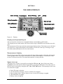
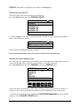
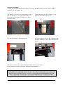
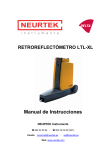
1
LTL-X RETROMETER Manual On site quality control of road markings & road surfaces in accordance with CEN / ASTM specifications DELTA · Venlighedsvej 4 · 2970 Hørsholm · Denmark · Tel. (+45) 72 19 40 00 · Fax (+45) 72 19 40 01 DISCLAIMER The information contained in this document is subject to change without notice. DELTA LIGHT & OPTICS MAKES NO WARRANTY OF ANY KIND WITH REGARD TO THIS MATERIAL, INCLUDING, BUT NOT LIMITED TO, THE IMPLIED WARRANTIES OF MERCHAN-TABILITY AND FITNESS FOR A PARTICULAR PURPOSE. DELTA LIGHT & OPTICS SHALL NOT BE LIABLE FOR ERRORS CONTAINED HEREIN OR FOR INCIDENTAL OR CONSEQUENTIAL DAMAGES IN CONNECTION WITH THE FURNISHING, PERFORMANCE OR USE OF THIS MATERIAL. Caution: Changes / modifications not approved by the responsible party could void the user’s authority to operate the equipment. NOTE: This equipment has been tested and found to comply with the limits for a Class A digital device, pursuant to part 15 of the FCC Rules. These limits are designed to provide reasonable protection against harmful interference when the equipment is operated in a commercial environment. This equipment generates, uses, and can radiate radio frequency energy and, if not installed and used in accordance with the instruction manual, may cause harmful interference to radio communications. Operation of this equipment in a residential area is likely to cause harmful interference in which case the user will be required to correct the interference at his own expense. Rev. 15 August 2012 SW ver: (MMC V3.04 up) ii LTL-X Retrometer DELTA DELTA LTL-X Retrometer iii iv LTL-X Retrometer DELTA TABLE OF CONTENTS SECTION 1................................................................................................................................ 7 OPERATING INFORMATION ...................................................................................................... 7 LTL-X introduction .................................................................................................................................. 7 LTL-X retrometer features ........................................................................................................................ 8 Options...................................................................................................................................................... 8 Getting started ........................................................................................................................................... 9 Important guide lines for the correct use of the LTL-X .......................................................................... 12 SECTION 2.............................................................................................................................. 14 GENERAL INFORMATION ........................................................................................................ 14 The measurement .................................................................................................................................... 14 Optical principle ..................................................................................................................................... 15 Notes on error sources ............................................................................................................................ 16 High temperature conditions. .................................................................................................................. 16 SECTION 3.............................................................................................................................. 17 THE USER INTERFACE .............................................................................................................. 17 Display and keyboard layout .................................................................................................................. 17 Measurement display .............................................................................................................................. 17 Upper icon row ....................................................................................................................................... 17 Lower icon row ....................................................................................................................................... 18 Pushbuttons ............................................................................................................................................. 18 The menu tree ......................................................................................................................................... 20 SETTING UP FOR MEASUREMENTS ...................................................................................... 21 Selecting a user ID .................................................................................................................................. 21 Selecting a road marking icon................................................................................................................. 22 Setting the date and time ......................................................................................................................... 23 Setting the display, contrast and back light ............................................................................................. 25 Setting the sound level ............................................................................................................................ 25 Setting the language ................................................................................................................................ 25 Setting the SMART key function ........................................................................................................... 25 Setting the aux functions ......................................................................................................................... 26 Setup ....................................................................................................................................................... 28 Auto off................................................................................................................................................... 29 Series id ............................................................................................................................................ 30 Working with series ID (name)............................................................................................................... 30 Activate ................................................................................................................................................... 30 Selecting a series ID ............................................................................................................................... 30 Enter a new series ID .............................................................................................................................. 30 Removing a series ID .............................................................................................................................. 31 Setting the road marking icon ................................................................................................................. 31 The log .............................................................................................................................................. 33 Clearing data in the log ........................................................................................................................... 33 Amending clear data. .............................................................................................................................. 33 Viewing the log....................................................................................................................................... 34 View series data. ..................................................................................................................................... 35 Log status ................................................................................................................................................ 35 Setting the log type ................................................................................................................................. 36 Other settings .................................................................................................................................. 37 Average function .................................................................................................................................... 37 Editing names ......................................................................................................................................... 38 Diagnosis ................................................................................................................................................ 39 Choosing output device .......................................................................................................................... 39 The help system ...................................................................................................................................... 39 Errors and warnings ................................................................................................................................ 39 DELTA LTL-X Retrometer v Default settings / user reset ..................................................................................................................... 40 RSC program .......................................................................................................................................... 40 SECTION 4.............................................................................................................................. 41 MAINTENANCE ............................................................................................................................ 41 General care ............................................................................................................................................ 41 Protection window .................................................................................................................................. 41 Battery .................................................................................................................................................... 41 Fuses ....................................................................................................................................................... 43 Lamp ....................................................................................................................................................... 43 Calibration unit ....................................................................................................................................... 44 Calibration .............................................................................................................................................. 45 Printer ..................................................................................................................................................... 47 Mounting the wet night rails for rain measurements .............................................................................. 48 Mounting the wheel unit (option) ........................................................................................................... 50 APPENDIX A .......................................................................................................................... 51 COMMUNICATION FACILITIES .............................................................................................. 51 Communication specification ................................................................................................................. 51 APPENDIX B .......................................................................................................................... 52 SPECIFICATION ........................................................................................................................... 52 General characteristics ............................................................................................................................ 52 Electrical characteristics .......................................................................... Error! Bookmark not defined. Environmental characteristics ................................................................................................................. 53 Mechanical characteristics ...................................................................................................................... 53 APPENDIX C .......................................................................................................................... 54 DELIVERY ..................................................................................................................................... 54 vi LTL-X Retrometer DELTA SECTION 1 OPERATING INFORMATION LTL-X introduction The LTL-X retroreflectometer is a portable field instrument intended for measuring the retroreflection properties of road markings in car headlight illumination, the value RL (coefficient of retroreflected luminance) is used. RL is a measure of the lightness of the road marking as seen by drivers of motorized vehicles in car headlight illumination. The road is illuminated at an angle of 1.24 and the reflected light is measured at an angle of 2.29, which corresponds, to an observation distance of 30 meters. This is relevant for a motorist’s viewing situation under normal conditions. RL is an important factor in the ON-SITE quality control of road markings. The operation of the retrometer is very simple and requires minimal instruction. The LTL-X measures the retroreflectivity and calculates RL according to international agreements. Results are presented in plain text on a large graphic display. Error messages or warnings are shown in the display in case of any problems during use. The built-in printer and memory provides registration of measurements with corresponding date and time and other important data. The following data is also registered (if enabled): DELTA LTL-X Retrometer 7 Name of measuring series (road name). Profile (icon) for road marking. User initials. GPS data (if installed). Communication with a PC using the RSC-program (see pg. 40) allows for data exchange with other PC programs, extended command, calibration, diagnostics and other facilities. A rechargeable NiMH battery powers the LTL-X, giving hours of measurement capacity. A mains powered battery charger power supply is supplied as standard. The instrument can also be charged from a 12-18V source such as a car battery using an adapter. LTL-X retroreflectometer features Portable self-contained instrument Small dimensions / low weight Ergonomic operation height Fast measurement (completed in less than 1 sec) Measuring on dry and wet surfaces (or the continuous wetting measurement method) Will measure flat, textured & profiled markings Built-in thermal printer Fully documented measurements with automatic data storage, user and series identification for labeling and grouping measurements Audible signals during use RSC PC software for data exchange, extended control, etc. Log data can be exported to applications such as Microsoft Excel Easy calibration procedure Traceable and accredited calibrated reflection standard User replaceable battery Fast charging (approx. 1 hour) Rechargeable from power adapter or a car battery using an adapter Average (2-25 readings) Multiple languages Wheel unit Options 8 GPS, for precise logging of measuring location Large battery pack with more capacity for extended use between charges LTL-X Retrometer DELTA Getting started Buttons: HELP ON/OFF MENU SMART HOME CALIBRATE BACK PRINT/OUT UP LEFT RIGHT OK (center) DOWN Figure 1. Buttons Height adjustment Before using the LTL-X, notice that the operating panel can be adjusted in height for ergonomic considerations. The height is adjusted by pressing the red knob on the front of the instrument and at the same time lifting the handle on the operating panel. Release the knob and continue lifting until the handle locks. Measuring Turn on the LTL-X by pressing and holding the ON/OFF button until the welcome message appears. The display will then change to the measure mode. (An exception is when the instrument is set to ask for user identification, see User select in this section). Calibrate the instrument if necessary. See Calibration in this section. Place the instrument on the road marking. Press the green OK-button approx. 1 sec. to take a measurement. A measurement will be finished in When the measurement is complete, the RL value will be displayed. Data is automatically transferred to the data log. If there is a problem with the measurement a warning icon or an error icon will pop up (see Warnings and errors, see pg. 39) and an audible alarm will sound (if enabled, see Sound settings). Measurements taken with a battery voltage that is too low are rejected or marked in the log and an error icon appears. To print the last measurement data, press the PRINT/OUT button . The Print/Output function must be set to Int. (See pg. 39). Printing can be stopped by pressing the PRINT/OUT button or the ON/OFF button for approximately 0.5 sec. DELTA LTL-X Retrometer 9 User select (user initials) If a user icon is displayed in the upper icon row on the measuring display, press the UP button ▲and if necessary ◄ or ► to mark the user icon. Press the OK button to enter the user select menu. For further information see Selecting a user id, pg. 21 Series ID select (name) From the HOME screen (measure display) press the UP button ▲to mark the road icon . Press the OK button to enter the series ID select menu. Select a name from the list using UP or DOWN and accept with OK. Calibration The instrument is supplied with two calibration units, a reference calibration unit (black) and a field calibration unit (red). The reference calibration unit is factory calibrated and traceable to PTB. The field calibration unit must be calibrated against the reference calibration unit by the user at suitable intervals. The reference calibration unit is stored in the black protection box, and the field calibration unit in the grey protection box. Two steps are required for a complete calibration, zero calibration and reference calibration. The instrument will guide you through the procedure. Calibration procedure Zero calibration Press the CALIBRATION button once. Mount the calibration unit underneath the front end of the instrument by tilting the instrument slightly backward. Make sure that the end pins on the side of the calibration unit fit into the slots in the LTL-X. It is important that the calibration unit faces with the dark opening toward the instrument tower. The display will show the correct orientation of the calibration unit. Make sure that the calibration unit and the light trap is clean. Press the OK button to start zero calibration (black calibration). During calibration the lamp will flash a number of times. Reference calibration After zero calibration, the instrument is ready for the reference calibration (white calibration). The display will tell you to turn the calibration unit so that the white face is facing the instrument tower. Again, it is important that the pins on the side of the unit fit into the slots in the LTL-X. Press the OK button to start reference calibration. Check the value displayed, and if necessary, adjust the calibration value shown in the display so it matches the value stamped on the calibration unit. Press the OK button to perform the calibration. The calibration procedure is now complete. Remove the calibration unit and store it properly. Press OK to return to the measurement display. For further details see pg. 45. Control Calibration. Use in case of doubt during on site measurement. Follow the traceable calibration procedure using the red control calibration unit. Use the Rl value from the control calibration unit label. Transfer of calibration value. At regular intervals the traceable calibration value must be transferred from the reference calibration unit to the control calibration unit. 10 LTL-X Retrometer DELTA Mount the reference calibration unit and perform a complete traceable calibration. Replace the reference calibration unit with the control calibration unit and make a normal RL measurement. Label the Control Calibration unit with the value and the date. Warnings and errors An error or warning icon will appear in the upper row of the display if the LTL-X detects a problem. Press the UP button ▲ to get a description of the most serious error or warning. Now press the OK button to display a total list of all errors or warnings related to the measurement. Sound setting Press the MENU button and select SETTINGS / SOUND. Select KEY CLICK or SOUNDS to set the individual sound levels for key click and warning/error sounds. Use the UP ▲ or DOWN ▼ button to set the level. Accept the setting by pressing the OK button. A loud additional beep can be selected by pressing the OK button when BEEP is highlighted. Miscellaneous The HOME screen can be activated at any time by pressing the HOME button . Reset log: Press the MENU button and select LOG / CLEAR DATA. Now select from the menu: LAST, ALL or SERIES. Date and time: Press the MENU button and select SETTINGS / DATE & TIME. Use the UP ▲ and DOWN ▼ buttons to set the time and date. Accept the setting by pressing the OK button. Power save: Press the MENU button and select SETTINGS / AUTO OFF. Use ▲and ▼ to edit the auto turn off time. Data exchange / communication The RSC program, developed by DELTA for use on a PC, allows data to be exchanged between the LTL-X and a PC. See RSC-program, pg. 40. DELTA LTL-X Retrometer 11 Important guide lines for the correct use of the LTL-X Positioning of the instrument on the road marking Select an area of the pavement marking that is level when taking readings. The red dot on the side of the base cover indicates the center of the measurement field on flat markings. The measurement field is approx. 45 mm wide and 200 mm long. Ensure the pavement marking to be measured is free of debris before taking measurements. Make sure that the instrument is stable positioned. Reason: The LTL-X has three support pads, each with a small footprint. An uneven marking or a small piece of gravel trapped under one of the pads will move the measurement field and affect the reading. Taking the measurement Press the green OK button to take a single reading. Do not put pressure on the handle when taking a measurement. Reason: Pressure on the handle can affect the measurement geometry and thus influence the reading. Number of measurements. For accurate readings, do not take just one reading of a road marking. Three readings will give a more accurate result than one reading. Five readings will give a more accurate result than three readings, etc. Take the readings in adjacent areas of the marking. Let the instrument calculate the average of the readings (fixed or moving average options). Reason: A road markings retroreflectivity varies from area to area. It is not unusual to see variations of 5% - 20% when the instrument is moved even less than 10 mm/ ½” in either direction. Obstructions in front of the LTL-X Ensure the pavement marking to be measured is clear of any obstructions at least 1 meter/ 40 inches in front of the LTL-X. For example, do not stand in front of the instrument when taking the reading, and do not have anyone else standing in front of the instrument while taking the reading. Reason: The observation field of the LTL-X extends beyond the front opening of the instrument. RPM’s/retroreflective materials in front of the LTL-X Recommended Procedure: Ensure there are no retroreflective materials not belonging to the marking at least 1 meter / 40 inches in front of the LTL-X. For wet road markings this distance is 2 meters/ 80 inches. Examples of such materials are raised pavement markers, high visibility clothing and shoes with retroreflective properties. Whenever the user suspects that materials ahead affect the reading the material should be covered with a dark cloth. Reason: The observation field of the LTL-X extends beyond the front opening of the instrument, and such retroreflective materials can cause false readings. 12 LTL-X Retrometer DELTA Protection of the display/display shield. For the protection of the display and longevity of the instruments keep the display shield closed when the instrument is not used. For further information please see section 2. Remember: DELTA LTL-X is an optical precision instrument, handle with care. Keep the protection window and calibration unit clean. Store in a clean and dry environment. LTL-X Retrometer 13 SECTION 2 GENERAL INFORMATION The measurement The LTL-X retroreflectometer measures the RL (coefficient of retroreflected luminance) parameter. The RL parameter represents the brightness of road markings seen by drivers of motor vehicles by headlight illumination. In the LTL-X the illumination angle is 1.24 degrees and the observation angle is 2.29 degrees. According to both ASTM and CEN standards this angle simulates a driver’s viewing distance of 30 meters. The instrument’s illumination field is approximately 200 mm x 45 mm and the observation field is approximately 610 mm x 60 mm. The dimensions are given for plane surfaces. For real non-planar road markings the fields are elongated. The measurement field is identical with the illumination field. The figure below shows the placement of the fields for normal and continuous wetting operations. For continuous wetting measurements the instrument is raised 7 mm by mounting the wet night rails (See pg 48). In this operation the illumination/measurement field is placed just in front of the horizontal base cover allowing the continuous wetting. Figure: 2 – Measurement field 14 LTL-X Retrometer DELTA Figure: 3. Measurement field with wet night accessories mounted. The tower of the LTL-X contains the illuminating and observation system and the control electronics. At the bottom of the tower an optical system, with mirror, directs a beam of light toward the road surface through a dust-protection window. A polymer shielding covers the measuring area for normal operation (see above). The LTL-X is controlled by multiple microprocessors. It is operated with an extractable keyboard located at the top of the retrometer. It executes the measurement automatically by push of a button and presents the result on a display. The result is automatically transferred to the internal memory. The measurement, along with its corresponding time, date, and other data can be printed using the built-in printer. Optical principle The optical system in the LTL-X is covered by a patent pending. A long life xenon lamp in the top of the tower generates the light for the measurements. After a field stop the light is collimated by a lens and deflected through a mirror toward the road. The reflected light from the road uses the same mirror and lens. Between the lens and the photo detector field aperture, stops define the observation area. The illumination field is inside in the observation field. This is important to assure correct measurement on profiled markings. V spectral correction is achieved by use of advanced optical filters. DELTA LTL-X Retrometer 15 Notes on error sources Stray light can occasionally enter the instrument but will be insignificant under normal measurement conditions. Before each measurement, the LTL-X automatically evaluates the leakage and compensates for it before the readout. In case of a significant leakage level, a warning or error message is given and special precautions may be necessary. Instrument leak, drift and offset errors are compensated by means of data obtained during the calibration procedure. It is very important to keep the light trap, the dust-protection window and the ceramic on the calibration unit clean. The LTL-X illumination angle is 1.24° relative to the road surface. Because of this small angle accurate placement on the road is important. Avoid pebbles and abnormal irregularities. The LTL-X must be parallel and in contact with the marking surface. The LTL-X retrometer is a rugged instrument, but it is an optical instrument and must be handled as such. The LTL-X is factory calibrated. Nevertheless start measurements with a calibration. Study the display for any warning or error icons. See also Section 4 - Maintenance Note Keep the light trap, dust-protection window and ceramics on the calibration unit clean. Keep the battery fully charged. A well charged battery is more resistant to aging and damage. High temperature conditions. Display If the display is exposed to intense direct sunlight during a longer period of time the display could become overheated. To reduce heat an IR-reflecting filter is mounted on the display. It is recommended to close the protective display shield. The shield also protects against damages and scratches. "Daylight readable" displays are vulnerable to high temperatures. High temperature will decrease the display service life. When the display temperature exceeds 50C / 122F an audible alarm will sound. The alarm will sound for 20 second and then pauses for one minute. This sequence continues until the temperature is lowered or the instrument is turned off. The alarm can be suspended for one minute by pressing any key. Battery The battery is rated to maximum 45C / 113F operating temperature. 16 LTL-X Retrometer DELTA SECTION 3 THE USER INTERFACE Figure: 4 – Display Display and keyboard layout The user interface consists of a rectangular display surrounded by push buttons. The display has two main modes: the measurement display (HOME screen) and the menu display. The instrument will start up with the measurement display shown. The display area is divided into four areas: a large main display in the middle, an icon row at the top, a message or caption field underneath and an icon row at the bottom. Measurement display Here the last measured Rl value is presented with large digits together with other information. On the graphic above, all possible information is shown in the display. If a function is deactivated, it will not be shown. The actual date and time is always shown. Upper icon row The upper row of icons is accessed by pressing the UP button ▲. One of the icons is then highlighted (inverted) and can then be activated by pressing the OK button. The other icons in the row can be accessed by using the LEFT ◄ or RIGHT ►buttons. The meanings of the icons are (from left to right): Series ID (name) selection. User ID (initials) selection. Can be switched off (see pg. 21). Error/warning alarm. Will be shown in case of an error/warning (see pg. 39). GPS indication (see pg. 26). Battery status (see pg. 43). DELTA LTL-X Retrometer 17 Lower icon row From the lower icon row you can select a road marking icon that will be saved together with the measurement in the log (see pg. 21) for future measurement identification. Access the icons by pressing the DOWN button ▼. Use the LEFT or RIGHT button to mark the preferred icon. Pressing DOWN again shows more icon rows from a roll stack of four rows. One row, marked with a "PR" for "Preset" can be preset by the user (see pg. 31) and is saved separately for each measuring series. It will be the active icon row, ready for selection, when a measuring series is selected. The measuring schedule upload (see pg. 40) includes series ID and the six preset icons for each series. Activate the marked icon with the OK button or exit with the HOME or UP ▲ button. The selected icon is now shown in the left side of the HOME screen and the instrument is again ready for measuring. Other functionality regarding the lower icon row: Activating an already selected icon will cancel the activation and remove the icon from the main display (and no icon will be saved by the next measurement). When the measurement display is selected (with the MENU button or the BACK button) the lower icon row will be the same as when the measurement display was last shown. Pressing DOWN and then UP in the HOME screen will show the row with the currently selected icon marked. Pushbuttons OK When the message row shows MEASURE, press the OK button to take a measurement. In most other cases pressing the OK button will activate a highlighted selection. ON/OFF Turn the instrument ON or OFF. Press the button to turn ON the instrument. To turn it OFF hold down the button for about half a second until the display shows a farewell message. When the instrument is on, a short press on the button will turn on the display backlight (if enabled, see pg. 25). HOME Bring you back to the measurement display. BACK Backward one step in the menu, canceling new settings which has not yet been confirmed by the OK button. In most cases the LEFT button has the same function. 18 LTL-X Retrometer DELTA HELP Present a context sensitive help text. Another press on the button will open up a general help menu. Menu Selects the top level of the menu tree, the main menu. Use the UP and the DOWN buttons to scroll through the menu items. Press OK to select the highlighted item. In some cases it opens up future submenu levels. SMART This button is user programmable to one out of several functions, e.g. to clear the last measurement, see pg. 25. CALIBRATE Starts the calibration wizard, see pg. 45. PRINT/OUT Print out the last measurement or selected parts of the log to the internal printer or send data to the communication port, see pg. 39. DELTA LTL-X Retrometer 19 The menu tree MAIN MENU: SETTINGS SERIES-ID LOG AVERAGE DIAGNOSIS PRINT/OUTPUT SETTINGS: USER DATE & TIME DISPLAY SOUND LANGUAGE "SMART" AUX SETUP AUTO OFF USER: SELECT EDIT CLEAR SEL. AT START DATE & TIME: TIME FORM. DATE FORM. SET TIME SET DATE DISPLAY: CONTRAST BACK LIGHT SERIES-ID: ACTIVATE ENTER ID EDIT DELETE PRESET MARK LOG: CLEAR DATA VIEW LOG STATUS LOG TYPE AVERAGE: AVERAGE ON TYPE NUMBER RESET SOUND VOL. KEY CLICK SOUNDS BEEP AUX: GPS GPS TIMER DGPS CLEAR LOG: LAST DATA ALL DATA SERIES DATA VIEW LOG: LAST DATA ALL DATA SERIES DATA DIAGNOSIS: INSTRUMENT BATTERY MMC/OMU MIS. Figure: 5 – Menu tree 20 LTL-X Retrometer DELTA SETTING UP FOR MEASUREMENTS Selecting a user ID The user ID (user profile) is used to identify the operator and is saved in the log together with each measurement. It consists of up to four characters, for instance initials of the operator’s name. If enabled, it can be seen at the lower left side of the measurement display. Measurements can also be taken without a user ID. Eight user ID’s can be stored in the instrument. Certain instrument settings are stored individually for each user. Selecting a user will restore these settings. Following settings are stored: All sound settings SMART key Back light timer Instrument auto off timer Advanced / basic menu setup The select procedure. 1. If a user select icon is not seen in the upper icon row: Press the MENU button and select SETTINGS / USER / SELECT to display the SELECT USER menu. 2. If a user select icon is seen in the upper icon row: Press the UP button. Then, if necessary use the LEFT or RIGHT button to highlight the user icon. Press the OK button. The SELECT USER menu is shown: SELECT USER: OK Off KFP HEN JOHN U4 U5 U6 U7 U8 Now use the UP or DOWN button to highlight a user name. Press the OK button to accept the name. In case 1 press the HOME button to return to the HOME screen. In case 2 the apparatus will automatically return to the HOME screen. Changes made to the above mentioned individual instrument settings are automatically stored in the selected user ID. User names can be edited from the menu SETTINGS / USER / EDIT (see editing pg. 38). DELTA LTL-X Retrometer 21 Selecting OFF will deactivate the user function and set all individual instrument settings to default. Clear user USER: HEN SELECT EDIT CLEAR SEL. AT START OK NO Clearing the user id will rename the user name to its default name (U1 to U8) and all individual instrument settings are set to default. SELECT USER: OK Off KFP U2 JOHN U4 U5 U6 U7 U8 Select at start USER: JOHN SELECT EDIT CLEAR SEL. AT START OK YES Enabling SEL. AT START will force the user to select a user ID each time the LTL-X is turned on. The last used user ID is automatically highlighted. Press the MENU button and select SEL. AT START. Press OK to toggle between YES and NO Selecting a road marking icon The purpose of a road marking icon. The road marking icons are used as labels for the individual measurement corresponding to the measured road marking and will be saved in the log together with the measuring result. The icon will then be presented together with the corresponding measurement when viewing the log (see pg. 34) or by using the RSC program (see pg. 40). There are 24 icons to select from. Six of the icons can be programmed as individual presets for each series (see pg. 31) and will be ready for selection when a series is selected. 22 LTL-X Retrometer DELTA The procedure. From the HOME screen press the DOWN button. Then use the LEFT or RIGHT button to highlight the wanted icon. Pressing DOWN steps through and displays the four icon rows. Pressing UP will return to the HOME screen without selecting a new icon. Pressing the OK button will activate the selected icon. The selected icon is now shown in the left side of the measuring field and the instrument is again ready for measuring. Deactivating the profile icon. Activating an already selected marking icon will cancel the activation and remove the icon from the main display. Setting the date and time Date and time is always shown in the display. Every measurement taken is marked with the date and time, so it is essential that the settings are correct. Press the MENU button and select SETTINGS / DATE & TIME. Press OK and the time format sub menu is shown. Setting the time format DATE & TIME OK TIME FORM.: DATE FORM.: SET TIME: SET DATE: 12 HR Y/MMM/D 02:34:56 PM 2001 NOV 24 Press OK when TIME FORM is highlighted. The time format menu is shown. TIME FORMAT: OK 24 HR 12 HR Highlight the preferred time format by using UP or DOWN. Press OK to accept. Setting the date format DELTA LTL-X Retrometer 23 Use UP or DOWN until DATE FORM is highlighted. Press OK and the date format menu is shown. DATE FORMAT: OK MMM/DD/YYYY MM/DD/YYYY DD/MMM/YYYY DD/MM/YYYY YYYY/MMM/DD YYYY/MM/DD YYYY/DD/MMM YYYY/DD/MM Highlight the preferred date format using UP or DOWN. Press OK to accept. Setting the time Use UP or DOWN until SET TIME is highlighted. Press OK and the time menu is shown. DATE & TIME TIME FORM.: DATE FORM.: SET TIME: SET DATE: OK 12 HR Y/MMM/D 02:34:56 PM 2001 NOV 24 Now use UP or DOWN to set the hour. Press the RIGHT button to select the minutes and repeat the procedure for minutes and seconds. Press OK to accept the setting. Note: the time in this menu is not live, but it will synchronize the time shown in the HOME screen. Setting the date Use UP or DOWN until SET DATE is highlighted. Press OK and the date menu is shown. Now use the same procedure as for setting the time. Note: Settings are first valid when OK is pressed. Until then you can abandon your changes with BACK or HOME. 24 LTL-X Retrometer DELTA Setting the display, contrast and back light The backlight time display shows how long the display backlight will be turned on. To turn on the light briefly, press . DISPLAY : CONTRAST BACK LIGHT: OK 5 60s Press the MENU button and select SETTINGS / DISPLAY. Select CONTRAST and press the OK button. The figure will be highlighted DISPLAY : CONTRAST BACK LIGHT: OK 5 60s Now use the UP or DOWN button to change the contrast. Accept by pressing the OK button or leave unchanged by pressing BACK, LEFT or HOME. The BACK LIGHT time is changed in a similar way. WARNING: Using the backlight will drain the battery faster! Setting the sound level Press the MENU button and select SETTINGS / SOUND. Select KEY CLICK or SOUNDS to set the individual sound levels for key click and warning and error sounds. Use the UP or DOWN button to set the level. Accept the setting by pressing the OK button or leave unchanged by pressing BACK, LEFT or HOME. A loud additional beep can be selected by pressing the OK button when BEEP is highlighted. This beep will be heard when a measurement cycle is completed. It lets the user know that it is ok to lift the instrument and move it to a new location. Setting the language Press the MENU button and select SETTINGS / LANGUAGE. Use the UP or DOWN button to select a language. Accept by pressing the OK button or leave unchanged by pressing BACK or LEFT. English can always be selected at power-up by pressing and holding the HELP key before ON is pressed. This will override any language selection. Setting the SMART key function This button is user programmable to one of several functions, e.g. to clear the last measurement Press the MENU button and select SETTINGS / SMART KEY: DELTA LTL-X Retrometer 25 SMART KEY: OK SELECT SERIES CLEAR LAST MEAS. RESET AVERAGE SER. ID ON/OFF Use the UP or DOWN button to select the SMART key function. Accept by pressing the OK button. The selected function is now accessed every time is pressed Setting the aux functions The Aux function is used to control auxiliary built-in equipment, e.g. a GPS receiver. AUX: OK GPS GPS TIMER DGPS ON OFF WAAS Using GPS (optional) The GPS receiver is mounted inside the instrument, drawing its power from the internal battery. The GPS system is used to supply position data (latitude and longitude) to the log together with the measurement data. If activated a GPS icon is shown in the upper icon row (see picture pg. 17). The icon will display the quality (reliability) of the GPS signal. If DGPS (Differential GPS) is selected, and a valid DGPS satellite is recognized, a "D" is added to the icon. This is illustrated in the FAIR reception icon below. In order to minimize the time required to get a GPS position fix after the LTL-X has been turned on, a "GPS TIMER" can be activated. This timer will keep the GPS unit powered up for 30 minutes after the instrument has shut off. If the instrument is turned back on within 30 minutes, the GPS will acquire a valid fix quickly. Below is an explanation of the GPS icon states. GOOD: The GPS HDOP (Horizontal Dilution Of Precision) value is below 5. D FAIR: The GPS HDOP value is larger than 5, but the GPS can FIX. NO: The GPS cannot FIX (weak or no signal). The GPS position data, HDOP value, and the number of satellites used in the position calculation are saved in the log together with the RL data. Activating the GPS Press the MENU button and select SETTINGS / AUX, highlight the GPS line and press the OK button to toggle the GPS ON or OFF. Press the HOME button to return to the HOME screen. 26 LTL-X Retrometer DELTA The GPS data can be viewed from the HOME screen by pressing the UP button and then highlighting the GPS icon by using LEFT or RIGHT buttons. Press the OK button to display the GPS data. When the GPS data changes the display is updated. If the GPS does not fix and a measurement is taken a warning menu appears. You will be presented with the following options: Measure anyway Skip measurement Turn off GPS GPS delayed off timer Press the MENU button and select SETTINGS / AUX, highlight GPS TIMER and press the OK button to toggle the timer ON or OFF. Press the HOME button to return to the HOME screen. If the timer is activated a message showing the delayed off time is shown in the display when the LTL-X is turned off. DGPS (WAAS / EGNOS) – optional. DGPS (Differential GPS) can improve the basic GPS accuracy. If DGPS is used, the GPS unit will receive correction data from the geostationary satellites such as WAAS, EGNOS and others. WAAS / EGNOS reception does not require additional receiving equipment. Currently, WAAS satellite coverage is only available in North America. Even though GPS users outside North America can receive WAAS, the signal has not been corrected and thus would not improve the accuracy of the position data. In some regions in the northern parts of the continent, the position of the satellites over the equator can make it difficult to receive the signals when trees or mountains obstruct the view of the horizon. EGNOS is the European counterpart of the WAAS satellite and the same limitations apply. Press the MENU button and select SETTINGS / AUX, highlight DGPS and press the OK button and the DGPS sub menu is shown. DGPS OK OFF WAAS EGNOS AUTO AUTO will automatically search for a DGPS satellite. When DGPS correction is selected the data is not necessary corrected immediately, it can take time to receive and process the correction signal. LTL-X will show if the correction data is used. The GPS icon in the upper row of the display will include a "D". If the GPS icon is selected, a line in the GPS screen will show the DGPS system used. If no correction system is selected, “N/A” will be displayed. The log data will also record the status of the correction system. When saving the log using the RSC2 program, the column “FIX” will show the value 2 if the DGPS correction was used. DELTA LTL-X Retrometer 27 It is not possible to see which correction system was used. For further information about the GPS system and WAAS / EGNOS webpages can be found that describe the systems and how they function. Map datum. The default map datum system is WGS84. There are more than 200 different map datums that can be selected. The selected datum can be seen in the GPS menu. The datum information is also stored in the log. Warning: Selecting the wrong map datum can result is substantial position errors! For further information on selecting the correct map datum system, please contact your local mapping software distributor. Contact your local distributor for futher information on changing the map datum in LTL-X. More about the GPS The GPS unit will typically acquire satellite signals and process a position fix in 5-40 seconds. If the GPS receiver has been turned off for a long period of time, the time to first fix will take longer. The GPS engine used have a navigation performance of 2.5 m CEP1) The precision of the GPS receiver in the LTL-X is determined by many factors. A few are listed below: Signal obstruction. The GPS receiver requires a clear view of the sky. Trees, buildings and other environmental objects can affect the satellite signals. Satellite constellation and geometry. Multi path (reflection of signal from buildings etc.). The HDOP (Horizontal Dilution of Precision) is a number that indicates the quality and precision of the received GPS data (low values are better than high). When the GPS is used, the operating time for the LTL-X will be decreased and you must charge the battery more often. 1) CEP (Circular Error Probable): A statistical measure of the horizontal precision. The CEP value is defined as a circle's radius, when centered at the true position, encloses 50% of the data points in a horizontal scatter plot. Thus, half the data points are within a 2-D CEP circle and half are outside the circle. Setup Setup is used to separate between advanced or basic users. The basic settings reduce the number of menus available to the user. For example, in basic menu operation, users cannot clear the log. The following menu points can be selected in basic mode: Settings: user, date & time, display, sound, setup. Log: status. Diagnosis. Print/output. 28 LTL-X Retrometer DELTA To change the setup, press MENU and select SETTINGS / SETUP. Pressing OK will toggle between ADVANCED and BASIC. To return from setup press BACK, LEFT or HOME. Auto off To save power, the instrument can be programmed to automatically shut off if not used. When communicating with RSC program the instrument will not power down automatically. Press the MENU button and select SETTINGS / AUTO OFF. Use UP and DOWN to edit the auto turn off time. The off time can be set from 60-300 sec. in intervals of 60 sec. or it can be deactivated (OFF) DELTA LTL-X Retrometer 29 SERIES ID Working with series ID (name) The purpose of a series ID. The series ID is a label. For example, it could be the name of the road. Although measurements can be performed without selecting a series ID, it is convenient to group (name) the measurements for each geographical spot, road or part of a road for easier recognition of each measurement. The series ID for such a group of measurements will be saved in the log together with the measuring results. The ID must be selected prior to the measurement. The individual measurements in a group can further be labeled by selecting a road marking icon (see pg. 31) corresponding to the actual road. Measurements taken with the same series ID are automatically marked with a unique number. The instrument can store 250 series ID’s. The series ID can be entered manually but it is far more convenient to enter the series ID’s in the RSC program (see pg. 40) and transfer them to LTL-X. Activate To use the series ID it must be activated. Press the MENU button and select: SERIES ID / ACTIVATE. By pressing OK you can toggle between ON and OFF, to activate or deactivate the series ID function. Press the HOME button to return to the HOME screen. When the series ID is off no ID is shown in the display and ID’s in the log marked: “No name”. Selecting a series ID From the HOME screen press UP. If necessary, use the LEFT or RIGHT button to highlight the road icon . Press the OK button. The SELECT SERIES menu is shown: SELECT SERIES: OK NEW ROAD #2 HIGHWAY #1 HIGHWAY #2 HIGHWAY #3 Now use the UP or DOWN button to highlight a series name. If the symbol ">" is displayed in the top right corner then more series can be accessed by pressing the RIGHT button. Press the OK button to accept the name. The instrument will now return to the HOME screen. Enter a new series ID Do the same as above but select NEW from the series list (or select MENU / SERIES ID / 30 LTL-X Retrometer DELTA ENTER ID). Proceed by spelling the series name (see Editing pg. 38). Removing a series ID This will remove the series ID from the selection list. Press the MENU button and select SERIES-ID / DELETE: DELETE SERIES-ID OK ROAD #1 ROAD #2 HIGHWAY #1 HIGHWAY #2 HIGHWAY #3 1 11 04 2001 - 11 04 2001 Use UP or DOWN to select the series that should be deleted. Accept by pressing the OK button. A confirm menu is shown: DELETE SERIES? OK NO YES, ALSO IN LOG Select with UP or DOWN and accept with OK. Note! All measurements in the selected series will be erased from the log! Setting the road marking icon Six of the 24 icons symbolizing road markings can be programmed as individual presets for each series ID and will be ready for selection when a series ID is selected. Press the MENU button and select SERIES-ID to enter the SERIES ID menu: SERIES-ID OK ACTIVATE: OFF ENTER ID EDIT DELETE PRESET ROAD MARKINGS HIGHWAY #10 used: 6/200 This menu shows in the bottom of the display the name of the actual series, the number of used series out of the total and the current preset row of markings for the actual series. To edit the preset marking icons, highlight the PRESET ROAD MARKINGS and press the OK button to show THE SELECT PRESETS menu: DELTA LTL-X Retrometer 31 SELECT PRESETS: ◄► OK The bottom line shows the present six preset icons. Use the LEFT, RIGHT, UP and DOWN buttons to choose a new icon for the first position, accept by pressing the OK button and the cursor (frame) will move to the second icon. Repeat for all six icons and the programming is done. You can amend at any point by pressing the BACK button and start over again. 32 LTL-X Retrometer DELTA THE LOG Each time a measurement is taken data is stored to the log. The following data are saved, if enabled: Measurement result incl. average Date and time. Name of measuring series (road name) and sequence number. Road marking icon User initials. GPS data (if installed). Status The instrument can store 1500 measurements in the log. Clearing data in the log Press the MENU button and select LOG / CLEAR DATA: CLEAR LOG: OK LAST DATA ALL DATA SERIES DATA This menu gives the option to clear data, either the last measurement, all measurements or one of the measuring series stored in the log. By pressing the OK button you will be asked to confirm the erasure of the data: CLEAR ALL DATA OK NO YES If you selected SERIES, you may select the series you wish to delete from the log from the list shown. Only the log entries will be erased. The series will still be available in the series select list. Amending clear data. The clear all option can be amended, but only until a new measurement is taken. To amend clearing all data, again choose LOG / CLEAR DATA / ALL DATA. If you have not taken a measurement after having deleted ALL DATA, the menu will now look like this: CLEAR ALL DATA NO YES UNDO OK EMPTY Simply choose UNDO and OK to restore the log. DELTA LTL-X Retrometer 33 Viewing the log Press the MENU button and select LOG / VIEW LOG: VIEW LOG: OK LAST DATA ALL SERIES This menu gives the possibility to view or print data from either the last measurement, from all measurements or from one of the measure series stored in the log. The figure below shows the ALL menu. RL 159 159 159 144 158 151 150 TIME STATUS OK > 1 2:3 4:5 6 0 GPS 1 2:3 4:5 5 0 GPS 1 2:3 4:5 4 0 GPS NF 1 2:3 4:5 2 0 1 2:3 4:5 1 0 1 2:3 4:4 2 0 1 2:3 4:2 7 0 2001 NOV 12 : PRLC Avg:159 #1/4 HIGHWAY #10 #5/5 In each line, the menu shows the Rl value, the time and the status, starting with the most recent measurement. To view a list of the individual errors/warnings in the status, print out the measurement (see below). By pressing the DOWN or UP button, the individual measurements are highlighted and corresponding data are shown in the bottom of the display. These data are: date, users initials, average information, series ID, number of measurement / total measurements in that series and finally the marking icon selected (if any). Each time a measurement is taken, a status information is generated. If any error occurs the information can be interpreted by the warning/error icon in the top line of the display. The information is available until a new measurement is taken. The status information is also stored in the log. The status is a coded number, where 0 (zero) indicates that every thing is ok. GPS indicates that valid GPS data was stored with the measurement. GPS NF indicates that the GPS had no fix during the measurement. To get further information about the measurement the status number can be interpreted by the RSC program. The arrow > in the top indicates that there are more entries (another page) to view, by either pressing the RIGHT button or using the DOWN button to roll the bar past the bottom. Also, if a left arrow < appears in the top, left corner, you can access a previous page by press34 LTL-X Retrometer DELTA ing the LEFT button or rolling the bar out of the top by pressing the UP button. To return to the log menu, press OK or BACK Printing. Press the PRINT / OUT button to print the log from the highlighted measurement to the end of (newest data) the log. The printing can be aborted at any time by pressing and holding the PRINT / OUT button or the ON / OFF button for about 0.5 sec. Release the button as soon as the printing stops. View series data. In the log menu, select SERIES to view the list of series: VIEW SERIES: OK ROAD #1 ROAD #2 HIGHWAY #1 HIGHWAY #2 HIGHWAY #3 1 11 04 2001 - 11 04 2001 The menu shows a series ID in each line. By pressing DOWN or UP, the individual series are highlighted and corresponding number of measurements taken and the date interval for the measurement are shown in the bottom of the display. These data are: the number and the date interval for the measurement taken in the series. Highlight a series and press the OK button to view the individual measurements. To return to the VIEW SERIES menu, press the OK or the BACK button. Printing. Highlight a series name and press the PRINT / OUT button to print all the series data from the highlighted measurement to the end (newest data) of the log. Highlight a measurement in the individual display and press the PRINT / OUT button to print the log from the highlighted measurement to the end of the series. The printing can be aborted at any time by pressing and holding the PRINT / OUT button or the ON / OFF button for about 0.5 sec. Release the button as soon as the printing stops. Log status To see how much of the memory is used, press the MENU button and select LOG / STATUS: LOG STATUS OK LOG USED: 104 LOG FREE: 1396 SERIES USED: 15 SERIES FREE: 235 DELTA LTL-X Retrometer 35 In the case shown above, there are 104 measurements in the log, leaving room for 1396 more. There are 15 measuring series in the log, leaving room for 235 more. Setting the log type You can choose between two different log types: Erase oldest: The oldest measurement will be overwritten by the newest measurement. Warn At Full: A warning will be issued when the log is full and the measurement will not be saved. Press the MENU button and select log. Highlight the line LOG TYPE by using the DOWN button: LOG: OK CLEAR DATA VIEW LOG STATUS LOG TYPE: ERASE OLDEST By pressing the OK button you can change the type of response when the log is full. 36 LTL-X Retrometer DELTA OTHER SETTINGS Average function An average function can be activated showing the average of the measured Rl value calculated over a selectable number of measurements (2 to 25). The average mode can be fixed or moving. In moving mode the average is always calculated from the last N measurements where N is the selected number of measurements. In fixed mode the averaging will start over again when N measurements have been taken. The average data is shown in the HOME screen at the lower right corner (see picture pg. 17). The average value is not stored in memory. Press the MENU button and select AVERAGE: AVERAGE AVERAGE: TYPE: NUMBER: RESET OK ON MOVING 10 AVERAGE: Use the UP or DOWN button to highlight the first line. Press the OK button to toggle between AVERAGE ON and AVERAGE OFF. TYPE: Highlight the second line and press the OK button to toggle between type: MOVING and type: FIXED. NUMBER: Highlight the third line and press the OK button to focus on the NUMBER digits. Then use the UP or DOWN button to change the value between 2 and 25. Finally press the OK button to confirm the new value (or you can amend changes by pressing LEFT or BACK). The default setting is 4. RESET: Highlight the fourth line and press the OK button to reset the calculated average value and reset the number of measurements included in the average to zero. DELTA LTL-X Retrometer 37 Editing names From certain points you arrive to the EDIT menu e.g. by choosing NEW from the series list. EDIT USER: ►◄▼▲OK A B C D E F I J K L M N Q R DEL INS END T U V W X Y # * : - / + 2 3 4 5 6 7 HANS G H O P S Z @ 0 1 8 9 , 6 times 1/4 1. Accept the highlighted letter with OK or select a new letter with ,,,. To delete the marked letter: select DEL . To insert before the marked letter, select INS (insert). 2. Press the OK button to accept. The cursor moves one place to the right and the next letter is highlighted. 3. Repeat 1-2 to correct or add new letters. To move backwards, select and press the OK button the required no. of times. This mode is cancelled by using , , or . 38 LTL-X Retrometer EDIT USER: ►◄▼▲OK A B C D E F G H I J K L M N O P Q R DEL INS END S T U V W X Y Z @ # * : - / + 0 12 3 4 5 6 7 8 9 J ANS 4 times OK, 1/4 Example: change HANS to JANS. 1. Use and to place the upper cursor on J . Press the OK button to accept 'J' and further 3 times to accept the following letters. This places the lower cursor after the end of the name. The upper cursor will now stay on INS . DELTA EDIT USER: ►◄▼▲OK A B C D E F G I J K L M N O Q R DEL INS END T U V W X Y Z # * : / + 0 2 3 4 5 6 7 8 H P S @ 1 9 OK JANS Use to select finish editing. END and press OK to Finished Diagnosis Press the MENU button. Highlight the line DIAGNOSIS. Press the OK button, and the menu showing: INSTRUMENTS, BATTERY, BOARDS and MISCELLANEOUS will be seen. Each gives information aimed at extended service and factory use. All the information will be printed out if you press the PRINT button. Choosing output device Press the MENU button. Highlight the line PRINT / OUTPUT by pressing the UP button once: MAIN MENU SETTINGS SERIES-ID LOG AVERAGE DIAGNOSIS PRINT/OUTPUT: OK INT. By pressing the OK button you can change the output device: The two possibilities are: Int: The built-in printer will be used for output. Ser: The communication port will be used for output. The help system Press the HELP button to show a context dependent help page. Pressing HELP once more will present a general help menu in which you can highlight a subject by using the UP or DOWN button and the press the OK button to show the help text. Errors and warnings When a measurement is taken, a status number is generated and saved in the log together with the measurement. The status number reflects various conditions concerning the measurement. If a problem occurs, a warning icon or an error icon is show above the HOME screen and an audible alarm is sounded (if enabled) and error is stored in the log. To view the nature of the problem, press the UP button and the warning/error icon will be highlighted and the most severe problem will be stated in the message line underneath. Then press the OK button to view a total list of problems starting with the most severe. Press the OK button (alternatively BACK or LEFT) to return to the HOME screen. If the problem did not hinder the completion of the measurement, the erroneous Rl value will be saved in the log together with a status number, which can identify the problems when the log is evaluated using the RSC program. DELTA LTL-X Retrometer 39 Default settings / user reset At power up a combination of buttons can be pressed to reset the active instrument setting and restoring the default settings. Forced English menu and standard contrast: If the instrument is set to a foreign language and you can not find the language select menu, do the following: Turn off the instrument. Press and hold the button while turning on the instrument. Now you can find the language select menu and select the language you want. If you do not set a language the foreign language will return at the next start-up. Small factory reset: This non destructive reset can be used to set parameters to factory standards but will not erase the log, the series list, the user list or the preferred markings: Turn off the instrument. Press and hold the button while turning on the instrument. Factory reset: This will set all parameters to factory standards and will also erase the log, the series list and the user list: Turn off the instrument. Press and hold the and buttons while turning on the instrument. RSC program Main features of the RSC program delivered together with the LTL-X: Transfer of log data to a pc Export of log data to other programs e.g. spread sheets Printing reports of the log data Easy entry of series-ID to make your measurement task efficient and reliable Programmable user setup For more details see the separate user’s manual for the RSC program, found on the installation CD. 40 LTL-X Retrometer DELTA SECTION 4 MAINTENANCE General care The retrometer is constructed for outdoor use in ordinary good weather conditions. It will stand moist weather with wet roads, but caution must be taken against heavy rain and dirt. The LTL-X retrometer is an optical instrument and shall be handled as such. Avoid shock and vibration if possible. CAUTION! To reduce the risk of electrical shock, do not remove the cover. Protection window The protection window is accessible from underneath of the instrument. The protection window is coated with a high-efficiency anti-reflection coating. Take care not to damage this coating when cleaning. Compressed air or a fine brush can be used for removing loose particles/dust. If this is not sufficient the window should by cleaned using a soft paper tissue or cloth and some window cleaning liquid. Battery The LTL-X retrometer is powered by a 12V NiMH battery. Under normal use, this battery requires no maintenance. However it is recommended to keep the battery fully charged. A fully charged battery is more capable of withstanding degeneration. A battery charger power supply is provided as a standard accessory for charging the battery from mains. The output cable of the charger is equipped with a connector matching the connector in the instrument. Connect the charger to an outlet and the instrument. If the instrument was turned off the display will now show a moving text that explains the charging state (Charging/Trickle charging/Charging done/Is Charged and Charge Error). The battery icon in the upper right corner will also indicate the charging state. No harm will result from leaving the charger connected after the charging process. However, the instrument must be disconnected from the charger when disconnecting the battery from the wall outlet. In addition, the battery can be charged using any DC supply from 12-18 V. such as a car battery by using an inverter. When storing the instrument for a long period of time fully charge the battery. It is possible to install a larger battery pack to increase the operating time for the instrument. This is also recommended when using a GPS. DELTA LTL-X Retrometer 41 Replacing the battery A worn out battery will not hold a charge very long. When the battery is worn out it must be replaced. The user can do this. The battery is located in a compartment at the rear of the tower. To replace the battery, remove the screws from the back cover, and remove the cover Loosen the big screw at the battery cover. You can now remove the cover. Lift out the battery of the compartment Press the snap-on clip on the connector and carefully withdraw it from the printed circuit board The battery can now be removed and replaced. Refit in reverse order. Please check your local regulations for disposal of the battery. THE BATTERY SUPPLIED WITH LTL-X IS SPECIALLY DESIGNED FOR THE INSTRUMENT TO ENSURE SAFE USE. IF A NON DELTA SUPPLIED OR APPROVED BATTERY IS USED WITH LTL-X DELTA CAN TAKE NO RESPONSIBILITY FOR ANY DAMAGED CAUSED DUE TO THE PERFORMANCE OF THIS BATTERY. 42 LTL-X Retrometer DELTA Battery status The capacity of the battery can be seen from the icon in the upper icon row. Indicates that the battery is fully charged. Indicates that the capacity of the battery is high to fair The capacity is low. You should recharge the battery. The battery is almost empty. The battery voltage is shown as it was at the last measurement in idle (when the instrument is on but not taking a reading) and in loaded mode (when xenon lamp is charging). Select the battery icon (with UP, LEFT and OK). The display will then show the voltages. Fuses Two fuses are located in the battery compartment. The charging fuse protects the battery against short circuit and other errors in the charging connector, charger or charging system. The battery fuse protects the battery and electronics against short circuit and other errors in the electronic system. Always replace a blown fuse with one of equal rating See Electrical Characteristics pg. Error! Bookmark not defined.. To change the fuses you need access to the battery compartment. See replacing battery pg. 42. Carefully unscrew the plastic cap fuse holder by using e.g. a coin. Pull out the fuse from the cap and insert the new one and reassemble Charger fuse Main fuse Lamp The lamp is a long life xenon type and requires no maintenance. Only trained personnel should replace the lamp when replacement is required. DELTA LTL-X Retrometer 43 Calibration unit Reference The road marking is simulated by a piece of white ceramic (the reference) mounted on an aluminum profile. Ceramics have very stable optical properties because of the smooth surface. The reference Zero Signal Figure: 5 - Calibration normal To make sure that calibration of the retrometer is correct it is important that the ceramics and light trap on the calibration unit is clean and undamaged. Always keep the calibration unit well protected. If the ceramic is stained, scratched or broken, the calibration unit has to be replaced and calibrated. In case of dust on the ceramics surface of the traceable reference, the use of compressed air is recommended for removal. To clean the ceramic reference on the field calibration unit, the use of a soft damp cloth is recommended if compressed air fails to remove the dirt. If necessary, use a mild household detergent. A calibration transfer must always be completed after the field reference is cleaned. It is necessary to have the traceable reference available to perform the transfer prior to cleaning the field reference. To ensure reliable measurements, it is recommended that the calibration unit be periodically recalibrated to a traceable standard. DELTA Light & Optics offers calibration traceable to PTB (Physikalsich-Technishe Bundesanstalt). For information contact your distributor or DELTA. 44 LTL-X Retrometer DELTA Light trap The zero signal is simulated by a light trap mounted in the calibration unit in the opposite end of the reference. It is made of two glossy and black plastic sheets mounted at an acute angle. If clean this will provide very efficient light absorbing device. It is necessary to disassemble the light trap to clean it efficiently. Using a fine brush, clean pressurized air or a soft paper tissue/cloth and some window cleaning liquid can do the cleaning. Calibration The LTL-X is factory calibrated and very stable but a calibration should always be carried out before starting a new series of measurements. The instrument is supplied with two calibration units, a reference calibration unit (black) and a field calibration unit (red). The reference calibration unit is factory calibrated and traceable to PTB. The field calibration unit must be calibrated against the reference calibration unit by the user at suitable intervals. The reference calibration unit is stored in the black protection box, and the field calibration unit in the gray protection box. Figure: 6 – Calibration Calibration Two steps are required for a complete calibration, zero calibration and reference calibration. The instrument will guide you through the procedure. Calibration procedure Zero calibration Press the CALIBRATION button once. Mount the instrument upon the calibration unit. This is done by tilting the instrument slightly backward and then insert the unit underneath the front end of the instrument. Make sure that the pins on the side of the unit fit into the slots in the LTL-X. It is important that the calibration unit faces with the dark opening towards the instrument tower. The display will show the correct orientation of the calibration unit. Make sure that the calibration unit and the light trap are clean. Press the OK button to start zero calibration. During calibration the lamp will flash a number of times. DELTA LTL-X Retrometer 45 Figure: 7 – Placing the calibration normal. Reference calibration Now the instrument is ready for the next step and the display will tell you to rotate the calibration unit so that the white face is facing the instrument tower. Again it is important that the pins on the side of the unit fit into the slots in the LTL-X. Press OK to begin the reference calibration. Check the value displayed and if necessary adjust the calibration value shown in the display, so it matches the value stamped on the calibration unit. Press the OK button to perform the calibration. The calibration procedure is now complete. Remove the calibration unit and store it properly. Press OK to return to the measurement display. The instrument automatically compensates for zero signal, leakage and other known errors, and calculates a calibration factor. This process is fully automatic. If the calibration routine is followed precisely the retrometer will now display 'true' Rl. Always store the reference calibration unit in a dry and clean environment. 46 LTL-X Retrometer DELTA Printer The printer is a high-speed high quality mini thermal printer. It has only a few moving parts and does not require any special or periodic maintenance. It uses a thermal paper roll, width: 57.5±0.5 mm (2.26 in), diameter: max. 31 mm (1.22 in) Replacing paper Replacing the paper is simple. First, pull the little lever out with your finger and the cover will open into the paper roll compartment. Insert the new paper roll and let a short paper tail hanging out at the top. Close the cover with a firm push and with some of the paper sticking out. DELTA LTL-X Retrometer 47 Mounting the wet night rails for rain measurements In order to move the measurement field outside the horizontal base cover as shown on figure 3, page 15 the two wet night rails should be mounted. You will find two wet night rails in the carrying case. Be aware of that there is a left and a right one. Bushing for the wet night rail Mount the wet night rails by insert the rails into the bushing underneath the LTL-X 48 LTL-X Retrometer DELTA Fasten the wet night rails in the lid with the screws delivered with the rails. Make sure that the LTL-X is resting on the rails before lightening the screws. The Wet night rails are now ready for use. After use dismount the wet night feet by reversing above operations. DELTA LTL-X Retrometer 49 Mounting the wheel unit (option) A wheel unit can be mounted in the rear of the instrument for easy transportation during heavy use. The wheels are mounted easily to the rear by fastening the two nuts mounted on the wheel block. Nuts for fasten the wheels Figure: 10 – Mounting the wheels 50 LTL-X Retrometer DELTA APPENDIX A COMMUNICATION FACILITIES Communication specification LTL-X is equipped with a USB connection that enables the use of standard Windows PC for downloading measurement records from the internal data log The PC connects to the LTL-X using the USB device connector on the rear of the instrument and a cable coming with the instrument. DELTA LTL-X Retrometer 51 APPENDIX B SPECIFICATION General characteristics Illumination angle ............................................................................................................ 1.24º Observation angle ............................................................................................................ 2.29º Equivalent observer distance ........................................................................................... 30 m Observation angular spread .......................................................................................... ±0.17º Type 30m CEN Illumination angular spread horizontal ........................................................................ 0.33º Illumination angular spread vertical ............................................................................ 0.17º Field of measurement: Width .........................................................................................................50 mm (2.0 inch) Length (typ.)............................................................................................200 mm (7.9 inch) Min. reading (mcd·m2·lx-1) ................................................................................................... 0 Max. reading (mcd·m2·lx-1) ..................................................................................... Typ. 2000 Radio: ........................................................................................... EN 300440-1 V1.6.1:2010 EMC: ............................................... EN 301489-1 V1.8.1:2008, EN 301489-3 V1.4.1:2002 Safety : ...................................................... EN/IEC 60950-1 :2006, EN/IEC 60950-22 :2006 FCC: .................................................................................. 47 CFR, FCC Part 15B, Class A Power supply: Battery .................................................................................Built in 12 volt / 2.1 Ah NiMH External charger power supply ..................... Friwo FW7530/15 (100-240 VAC / 15VDC) Charging time .................................................................................. Approx. 1 hour 50 min Charger fuse (5*20 mm) .......................................................................................... T3.15A Power supply fuse (5*20 mm) ................................................................................. T3.15A Data memory ........................................................................................... 1500 measurements Data retention (from purchase) ............................................................................ Typ. 5 years Interface ............................................................................................................................USB 52 LTL-X Retrometer DELTA Environmental characteristics Temperature: Operating ........................................................................... 0ºC to + 45ºC (32ºF to +113º F) Storage*) .......................................................................... -15ºC to + 55ºC (5º F to +131º F) Humidity ......................................................................................... 85% and non-condensing *) Battery must be fully charged Mechanical characteristics Max. length .................................................................................................. 573 mm/ 22.56 in Max. width ..................................................................................................... 222 mm/ 8.74 in Max. height .................................................................................................. 538 mm/ 21.18 in Weight ...................................................................................................................9 kg/ 20 lbs Shipping weight ...................................................................................................20 kg/ 45 lbs Construction: Structural parts .................................................................................................... Aluminum Housing .................................................................................................................. Polymer Keyboard ...................................................................................................... Silicone rubber Circuit boards .................................................................................................... Epoxy glass Printer: Thermal paper ......................................width/dia. 57.5 ±0.5 mm / 31mm (2.26 in / 1.22in) DELTA LTL-X Retrometer 53 APPENDIX C DELIVERY 54 LTL-X Retrometer DELTA INDEX 3 E 30 meters · 5 Editing names · 36 EGNOS · 25 Electrical characteristics · 50 Enter a new series id · 28 Environmental characteristics · 51 Error icon · 37 Error sources · 14 Errors and warnings · 37 A Advanced · 26 Amending clear data · 31 Auto off · 27 Aux functions · 24 Average function · 35 Fixed · 35 Moving · 35 Number · 35 Reset · 35 Type · 35 B Back light (display) · 23 Battery · 39 Charging · 39 maintenance · 39 status · 41 Battery status · 41 Buttons · See Pushbuttons F Fixed · 35 Fuses · 41 G General care · 39 GPS · 24 Activating the GPS · 24, 25 HDOP · 26 GPS data · 25 Group · 28 H C Calibration · 43 Calibration procedure · 43 Calibration unit · 42 Light trap · 43 Reference · 42 CEP · 26 Clear user · 20 Clearing data in the log · 31 Communication · 49 Communication specification · 49 Continuous wetting · 12 Contrast · 23 Help · 37 HOME screen · 15 I Illumination field · 12, 13 Initials · 19 Int, Internal printout · 37 K Key · See Pushbuttons D Date · 21 Datum, Map · 26 Deactivating the profile icon · 21 Default settings · 38 Delayed off timer · 25 DELIVERY · 52 Detector · See Photo detector DGPS · 25 Diagnosis · 37 Display · 23 Display shield · 11 DELTA L Label · 28 Lamp · 41 Language · 23 Leakage · See Stray light Light trap · 43 Lightness of the road · 5 Log · 31 Log status · 33 Log type · 34 Low battery voltage · 7 Lower icon row · 16 LTL-X Retrometer 55 M Maintenance · 39 Map datum · 26 Measure display · 15 Measurement · 12 Measurement field · 12 measurement, number · 10 Mechanical characteristics · 51 Menu display · 15 Menu tree · 18 Mounting the plates/ feet’s for rain measurements · 46 Moving · 35 N Name · 28 Navigation performance · 26 New series id · 28 Notes on error sources · 14 Display · 14 High temp. · 14 Sun · 14 O Observation field · 12, 13 Off timer · 25 Operator · 19 Optical principle · 13 Output device · 37 P Photo detector · 13 Placement on the road · 14 Power save · 27 Preset profiles · 29 Printer · 45 Protection window · 39 Pushbuttons · 16 Back · 16 Calibrate · 16 Help · 16 Home · 16 Menu · 16 OK · 16 ON/OFF · 16 Print/Out · 16 SMART · 16 Reset · 38 Rl · 5, 7 Road icon · 28 Road marking profiles · 29 RSC-program · 38 S SEL. AT START · 20 Select at start · 20 Ser, Serial output · 37 Series id · 28 Setting the log type · 34 Setting the preset profiles · 29 Setup · 26 Advanced · 26 SMART key · 23 Sound level · 23 Specifications · 50 Stray light · 14 T Time · 21 Traceable · 42 U Upper icon row · 15 User id · 19 User interface · 15 User reset · 38 Users · 26 V View series data · 33 Viewing the log · 32 W Warning icon · 37 Warnings · 37 Wheel unit · 48 Window · 39 WAAS · 25 X R Rain measurements · 46 Receiver · 24 Reference · 42 Reference calibration · 44 Removing a series id · 29 Replacing the battery · 40 56 Xenon lamp · 13 Z Zero calibration · 43 LTL-X Retrometer DELTA