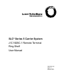
1
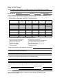
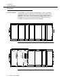
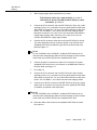
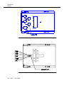
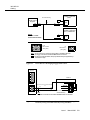
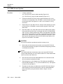
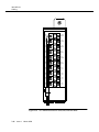
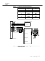
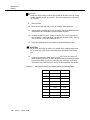
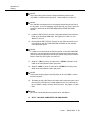
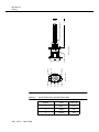
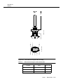
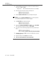
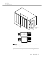
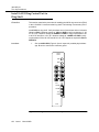
SLC® Series 5 Carrier System
J1C182BC-1 Remote Terminal
Ring Shelf
User Manual
363-205-121
Issue 1
March 2000
Copyright © 2000 Lucent Technologies. All Rights Reserved.
This material is protected by the copyright and trade secret laws of the United States and other countries. It
may not be reproduced, distributed or altered in any fashion by any entity, including other Lucent Technologies
Business Units or Divisions, without the expressed written consent of the Customer Training and Information
Products organization.
For permission to reproduce or distribute please contact:
Product Development Manager
1-800-334-0404
Notice
Every effort was made to ensure that the information in this document was complete and accurate at the time
of printing. However, information is subject to change.
Mandatory Customer Information
Federal Communications Commission (FCC) Statement
This equipment has been tested and found to comply with the limits for a Class A digital device, pursuant to
Part 15 of FCC Rules. These limits are designed to provide reasonable protection against harmful
interference when the equipment is operated in a commercial environment. This equipment generates, uses,
and can radiate radio frequency energy, and, if not installed and used in accordance with the instruction
manual, may cause harmful interference to radio communications. Operation of this equipment in a residence
is likely to cause harmful interference in which case the user will be required to correct the interference at his
own expense.
Security
In rare instances, unauthorized individuals make connections to the telecommunications network through the
use of remote access features. In such an event, applicable tariffs require that the customer pay all network
charges for traffic. Lucent Technologies cannot be responsible for such charges and will not make any
allowance or give any credit for charges that result from unauthorized access.
Trademarks
SLC and AnyMedia are registered trademarks of Lucent Technologies.
FAST is a trademark of Lucent Technologies.
AMP and Mate-N-Lok II are trademarks of AMP, Inc.
NO-OX-ID is a registered trademark of Sanchem, Inc.
Documentation Ordering Information
The ordering number for this document is 363-205-401. To order this document call 1-888-LUCENT8 or
1-888-582-3688. The RBOC/BOC customers should process document orders or standing order requests
through their Company Documentation Coordinator.
Customer Assistance and Technical Support
Follow local procedures for obtaining technical assistance. Lucent Technologies also provides in-hours or
emergency out-of-hours assistance for the SLC® Series 5 Carrier System. Call the Lucent Technologies
Regional Technical Assistance Center at 1-800-CAL-RTAC (1-800-225-7822).
Documentation Support
Lucent Technologies provides a telephone number for you to report errors or to ask questions about the
information in this document. The support telephone number is 1-800-334-0404 or 1-336-727-6681.
Developed by Lucent Technologies Network Systems Customer Training and Information Products (CTIP)
Organization.
How Are We Doing?
Title: SLC Series 5 Carrier System, J1C182BC-1 Remote Terminal Ring Shelf, User Manual
Identification No.: 363-205-121
Issue No.: 1
Date: March 2000
Lucent Technologies welcomes your feedback on this Customer Information Product (CIP). Your
comments can be of great value in helping us improve our CIPs.
1. Please rate the effectiveness of this CIP in the following areas:
Excellent
Good
Fair
Poor
Not
Applicable
Clarity
//////////////////
//////////////////
Completeness
//////////////////
Accuracy
//////////////////
Organization
//////////////////
Appearance
//////////////////
Ease of Use
Examples
Illustrations
//////////////////
Overall Satisfaction
2. Please check the ways you feel we could improve this CIP.
❒
❒
❒
❒
❒
❒
Improve the overview/introduction
Improve the table of contents
Improve the organization
Include more figures
Add more examples
Add more detail
❒
❒
❒
❒
❒
❒
Make it more concise/brief
Add more step-by-step procedures/tutorials
Add more troubleshooting information
Make it less technical
Add more/better quick reference aids
Improve the index
Please provide details for the suggested improvement.
3. What did you like most about this CIP?
4. Feel free to write any comments below or on an attached sheet.
If we may contact you concerning your comments, please complete the following:
Name:
Company/Organization:
Telephone Number:
Date:
Address:
When you have completed this form, please fold, tape and return to address on back
or Fax to: 336 727-3043.
------------------------------------------------------------ Do Not Cut — Fold Here And Tape ---------------------------------------------------------------------
NO POSTAGE
NECESSARY
IF MAILED
IN THE
UNITED STATES
BUSINESS REPLY MAIL
FIRST CLASS PERMIT NO. 1999 GREENSBORO, NC
POSTAGE WILL BE PAID BY ADDRESSEE
DOCUMENTATION SERVICES
2400 Reynolda Road
Winston-Salem, NC 27199-2029
Contents
About this Document
■
■
Overview
v
Purpose
v
Intended Audiences
v
How To Use This Document
v
Safety Instructions
vii
Product Safety
vii
Safety Labels
vii
Electrostatic Discharge Considerations
vii
Power Distribution Panel Warnings and Explanations
■
Related Documents
xi
■
How to Order Documents
xii
■
Lucent Technologies Contacts
xiii
Customer Assistance and Technical Support
■
1
xiii
How to Comment on This Document
xiv
General Description
■
2
ix
Overview
1-2
Shelf Description
1-2
3C1 Ringing Generator
1-3
AUG3 Ring Control Unit
1-3
Shelf Installation
■
Shelf Installation
2-2
Overview
2-2
Procedure
2-7
Issue 1
March 2000
iii
Contents
3
Cabling
■
Overview
General
■
■
AnyMedia Access System
Procedure
3-6
SLC-2000 Access System
SLC Series 5 Access System
3-12
3-12
3-22
3-22
Turnup Procedures
■
■
5
Install 3C( ) Ringing Generators in Ring Shelf
4-2
Overview
4-2
Procedure
4-2
Install AUG3 Ring Control Unit in Ring Shelf
4-6
Overview
4-6
Procedure
4-6
Maintenance and Trouble Clearing
■
Overview
General
Issue 1
March 2000
5-2
5-2
3C1 Ringing Generator
5-2
AUG3 Ring Control Unit
5-2
Procedure
iv
3-3
3-3
Procedure
4
3-2
Cable Assemblies
Procedure
■
3-2
5-3
About This Document
Overview
Purpose
This document provides instructions for installing, cabling, turning up, and
maintaining a J1C182BC-1 remote terminal ring shelf.
Intended Audiences
The document is intended for access system customers who install, cable, turn
up, and maintain equipment.
How To Use This
Document
This document is organized as follows:
■
“About This Document”
This section defines the purpose and intended audience for this
document; provides introductory and support information on this
document; and provides information on how to obtain technical support.
■
Chapter 1, “General Description”
This chapter describes the J1C182BC-1 remote terminal ring shelf. It
provides an illustration of the shelf that shows the location of the circuit
packs.
■
Chapter 2, “Shelf Installation”
This chapter provides installation procedures for the J1C182BC-1 remote
terminal ring shelf.
■
Chapter 3, “Cabling”
This chapter provides cabling procedures for the J1C182BC-1 remote
terminal ring shelf.
Issue 1
March 2000
v
About This Document
■
Chapter 4, “Turn up Procedures”
This chapter provides turn up procedures for the J1C182BC-1 remote
terminal ring shelf.
■
Chapter 5, “Maintenance and Trouble Clearing”
This chapter provides the maintenance and trouble clearing procedures
for the J1C182BC-1 remote terminal ring shelf.
vi
Issue 1
March 2000
About This Document
Safety Instructions
Product Safety
This section provides the product safety information relevant to this document.
!
WARNING:
Only trained service personnel should perform the procedures in this
document. These procedures allow exposure to high electrical energy that
may result in electric shock and/or injury to untrained personnel during
servicing, maintenance, and installation of this system.
Safety Labels
This document may contain Safety labels as DANGERS, WARNINGS, and
CAUTIONS. These safety labels have the following definitions.
!
DANGER:
Danger indicates the presence of a hazard that will cause death or severe
personal injury if the hazard is not avoided.
!
WARNING:
Warning indicates the presence of a hazard that can cause death or
severe personal injury if the hazard is not avoided.
!
CAUTION:
Caution indicates the presence of a hazard that will or can cause minor
personal injury or property damage if the hazard is not avoided. The
caution is also used for property-damage-only accidents. This includes
equipment damage, loss of software, or service interruption.
! is used on product labels and in this document it
The safety alert symbol
is used to alert the user to important operating and maintenance instructions.
Electrostatic Discharge Considerations
!
CAUTION:
Industry experience has shown that all integrated circuit packs can be
damaged by static electricity that builds up on work surfaces and
personnel. The static charges are produced by various charging effects of
movement and contact with other objects. Dry air allows greater static
charges to accumulate. Higher potentials are measured in areas with low
Issue 1
March 2000
vii
About This Document
relative humidity, but potentials high enough to cause damage can occur
anywhere.
The following list of precautions should be observed when handling
circuit packs to prevent damage by electrostatic discharge (ESD):
■
Assume all circuit packs contain solid state electronic
components that can be damaged by ESD.
■
When handling circuit packs (storing, inserting, removing, etc.)
or when working on the backplane, always wear a grounded
wrist strap or wear a heel strap and stand on a grounded,
static-dissipating floor mat. If a static-dissipating floor mat is
used, be sure that it is clean to ensure a good discharge path.
■
Handle all circuit packs by the faceplate or latch and by the top
and bottom outermost edges. Never touch the components,
conductors, or connector pins.
■
Observe warning labels on bags and cartons. Whenever
possible, do not remove circuit packs from antistatic packaging
until ready to insert them into slots.
■
If possible, open all circuit packs at a static-safe work position,
using properly grounded wrist straps and static-dissipating
table mats. If a static-dissipating table mat is used, be sure that
it is clean to ensure a good discharge path.
■
Always store and transport circuit packs in static-safe
packaging. Shielding is not required unless specified.
■
Keep all static-generating materials such as food wrappers,
plastics, and foam packaging away from all circuit packs. On
removal from the bay, immediately put circuit packs into staticsafe packages.
■
Whenever possible, maintain relative humidity above 20
percent.
To reduce the possibility of ESD damage, shelves are equipped with
grounding jacks to enable personnel to ground themselves using wrist
straps (Figure 1) with a minimum resistance of 250 k-ohms while
handling circuit packs or working on a shelf/shelves. When grounding
jacks are not provided, an alligator clip adapter enables connection to
bay frame ground.
viii
Issue 1
March 2000
About This Document
To
Ground
Connection
Figure 1.
Power Distribution
Panel Warnings and
Explanations
Static Control Wrist Strap
This section provides power distribution panel warnings and explanations
relevant to this document.
!
CAUTION:
Hazardous voltage/energy inside. Risk of injury. This unit should be
accessed only by qualified personnel.
This unit must be installed, serviced, and operated only by skilled and qualified
personnel that have the necessary knowledge and practical experience with
electrical equipment, and understand the hazards that can arise when working
on this type of equipment.
!
CAUTION:
Inserting fuses into live plant will cause arcing and sparks. Risk of eye
injury. Always wear safety glasses. Fuses can produce sparks.
For situations where fuses are used and the loads are capacitive, arcing will
occur and sparks will exit from the back of the fuse holder and may even exit out
the front when the fuse disconnect head is inserted into the fuse holder base
while power is still applied to the circuit. Arcing may be more severe at times due
to the discharge state of any downstream capacitors and the amount of charged
capacitance in parallel with the circuit. Therefore, follow all appropriate safety
precautions when you insert fuses (for example: wear safety glasses). Make
Issue 1
March 2000
ix
About This Document
sure other personnel are clear from the front and back of the unit. Do not stand
directly in front of the holder when inserting fuses. Try to insert fuse into the fuse
holder base quickly to reduce the amount of arcing.
!
CAUTION:
Battery voltage present. Risk of injury due to high current. Avoid
contacting conductors with non-insulated metal objects. Follow Safety
Precautions.
Batteries can be connected in parallel with rectifiers. If you turn off rectifiers, it
does not necessarily remove power from the bus. Ensure that the battery power
is also disconnected. Follow the safety procedures while you work on any
equipment that contains hazardous energy or voltage.
!
CAUTION:
100 volts AC present on fuses.
The ringer circuits contain hazardous secondary AC voltages at 100 V. This
potential is present on internal connectors, printed wiring boards (PWBs), and
on the fuses. Do not touch exposed fuse indicator terminal while the fuse is
inserted in holder.
x
Issue 1
March 2000
About This Document
Related Documents
The following documents provide additional information about the J1C182BC-1
remote terminal ring shelf circuit packs.
363-005-226
3C1 Ringing Generator - 5SCB644XXX, Data Sheet
363-005-242
AUG3 Ring Control Unit - 5SCBM00GXX, Data Sheet
Issue 1
March 2000
xi
About This Document
How to Order Documents
To order additional copies of this document (363-205-121) and/or to request
placement on the standing order list, send or call in an order as follows:
Customer
Mail Order
Commercial
customers1
Lucent Technologies
Customer Information Center
Attention: Order Entry Center
2855 N. Franklin Road
P.O. Box 19901
Indianapolis, IN 46219
RBOC/BOC
Telephone Order
(Monday Through Friday)
Within USA and Canada:
1-888-LUCENT-8 (582-3688)
7:30 a.m. to 6:30 p.m. EST
FAX: 1-800-566-9568
Worldwide:
FAX: 1-317-322-6699
Process through your Company Documentation Coordinator
1. For commercial customers, a check, money order, purchase order number,
or charge card number is required with all orders. Make checks payable
to Lucent Technologies. Lucent Technologies entities should use Form IND
1-80.80 FA, available through the Customer Information Center.
One-time orders include a binder (if applicable) and the document contents for
the current issue in effect at the time of order. Also, you may request placement
on the standing order list for all later reissues of any document. The standing
order list for each document provides automatic distribution for all reissues of the
document. RBOC/BOC customers should process document orders or standing
order requests through their Company Documentation Coordinator.
xii
Issue 1
March 2000
About This Document
Lucent Technologies Contacts
Customer Assistance Lucent Technologies provides customer assistance on the J1C182BC-1 remote
terminal ring shelf, including, but not limited to, troubleshooting assistance,
and Technical
technical consultation, operational problem consultation, procedural advice, and
Support
emergency recovery assistance from a qualified system support professional
from the Regional Technical Assistance Center (RTAC).
Service is provided from the RTAC at 1-800-CAL-RTAC (1-800-225-7822). This
telephone number is monitored 24 hours a day, 7 days a week. During regular
business hours your call will be answered by your local regional RTAC
representative. Outside normal business hours, all calls will be answered at a
centralized technical assistance center where service-affecting problems will be
dispatched immediately to your local RTAC. All other problems will be referred to
your local RTAC on the next regular business day.
Issue 1
March 2000
xiii
About This Document
How to Comment on This Document
Feedback forms are located immediately after the title page of this document. If
the feedback forms are missing, please send your comments and suggestions
to:
Lucent Technologies Customer Training and Information
Products Organization
Documentation Services
2400 Reynolda Road
Winston-Salem, NC 27106-4606
xiv
Issue 1
March 2000
1
General Description
Contents
■
Overview
1-2
Shelf Description
1-2
3C1 Ringing Generator
1-3
AUG3 Ring Control Unit
1-3
Issue 1
March 2000
1-1
363-205-121
General Description
Overview
Shelf Description
The J1C182BC-1 remote terminal ring shelf (Figures 1-1 and 1-2) is used to
supply ringing voltage to a SLC Series 5, SLC-2000 Access System, or to an
AnyMedia access system. The ring shelf has two ringing voltage supplies
(GROUPs 1 and 2), each of which contains two ringing generators (3C1 circuit
packs) and one ring control unit (AUG3 circuit pack). The ring shelf can be
mounted in a standard 23-inch bay or in various cabinets.
GROUP 1
R IN G G E N 1
GROUP 2
R IN G G E N 2
Figure 1-1.
RCU
R IN G G E N 1
R IN G G EN 2
RCU
Unequipped J1C182BC-1 Remote Terminal Ring Shelf
G R O UP 1
G RO U P 2
Lucent
3C
R IN G ING
G EN ER ATO R
Lucent
3C
R ING IN G
G E NER ATO R
FAIL
FAIL
Lucent
A UG 3
RMJ
RMN
1
-48V
-48V
GND
GND
-20HZ
-20HZ
2
3
4
+20H Z
0.5A
-20H Z
0.5A
+20H ZA
+20H ZB
-48V
G ND
RCU
R IN G G EN 1
R ING G EN 2
Figure 1-2.
1-2
Issue 1
March 2000
RIN G G E N 1
R ING G EN 2
RCU
RCU
Partially Equipped J1C182BC-1 Remote Terminal Ring Shelf
363-205-121
General Description
3C1 Ringing
Generator
The 3C1 ringing generator provides a 20-Hz negative-superimposed ringing
current to satisfy ringing requirements.
!
DANGER:
The ringing generator contains hazardous voltage when inserted into its
slot.
The 3C1 ringing generator contains a DC-DC converter that converts nominal -48
volts into those DC voltages needed for internal operations. The -48 V input fuse
is located in the 3C1 ringing generator. A 20-Hz reference circuit controls a power
bridge arrangement to generate the 20-Hz ringing signal. Low-pass filtering is
provided at the output of the power bridge to remove switching transients.
The 3C1 ringing generator can simultaneously ring 50 telephones. The 3C1
ringing generator supplies 20-Hz, 100 V rms (up to 400 mA rms) ringing
superimposed on approximately -55 V DC (up to 180 mA). The output is current
limited to one ampere under short circuit conditions. Control circuitry is provided
to allow remote shutdown and delayed start-up. Output signaling is provided to
control a protection switch or other ringing generator. An alarm lead signals
failure to an external monitor.
FAIL (Red LED): This LED lights to indicate an alarm when the 20-Hz ringing
voltage drops below approximately 60 volts for more than 5 seconds.
-48V, GND, -20HZ: Test jacks are provided on the faceplate – one for -48V DC,
one for ground, and one for 20-Hz ringing.
The ringing generator in the left-hand position of the group is the main ringing
generator. The other ringing generator provides protection if the main ringing
generator fails. When the main ringing generator is restored, service
automatically switches back to the main ringing generator.
AUG3 Ring
Control Unit
The AUG3 ring control unit (RCU) provides input and output fusing protection,
alarm indications, and alarm outputs. In addition, the AUG3 RCU performs the
following functions:
■
Controls the output of the ringing generators to feed two separate loads
■
Connects both ringing loads to the working ringing generator and transmits
a minor alarm if a ringing generator fails.
The RCU contains two positive ringing supplies used for multi-party service to four
or more parties. These supplies feed the two separate loads. The RCU also
provides backup for the positive ringing supply; if one fails, both loads are
connected to the other supply.
Fuses are 80G type, 0.5 amps, and provide output protection. These fuses are
accessible from the faceplate for replacement. An RMN (ringing minor alarm)
indicator (yellow) lights when an internal failure has caused a switch of the output
load to the protection source. An RMJ (ringing major alarm) indicator lights when
Issue 1
March 2000
1-3
363-205-121
General Description
one or more ringing outputs have failed (could be caused by dual circuit failures or
a blown output fuse). The faceplate jack provides convenient test access to the
20-Hz ringing sources.
1-4
Issue 1
March 2000
2
Shelf Installation
Contents
■
Shelf Installation
2-2
Overview
2-2
Procedure
2-7
Issue 1
March 2000
2-1
363-205-121
Shelf Installation
Shelf Installation
Overview
The J1C182BC-1 remote terminal ring shelf can be mounted in any standard 23inch wide bay or in various cabinets. The ring shelf requires -48 V DC to operate.
Figures 2-1 and 2-2 are examples that show typical bay arrangements (before and
after) for installing a J1C182BC-1 remote terminal ring shelf in a SLC-2000
Access System or a SLC Series 5 System. Explanations of Warnings found on
the Power Distribution Panels are provided in the “About This Document” section
of this manual.
NOTE:
If a baffle is not going to be installed above the ring shelf, you must leave 3
inches of free space above and below the ring shelf.
Figures 2-3, 2-4, and 2-5 show the ring shelf installed in an AnyMedia Access
system lineup.
Power
Distribution
Panel
-48 V Shelf
Free Space
Battery Shelves
Figure 2-1.
2-2
Issue 1
March 2000
Typical SLC-2000 (or SLC Series 5) System Bay Arrangement
Before Installing the Ring Shelf
363-205-121
Shelf Installation
Power
Distribution
Panel
-48 V Shelf
3” Free Space
J1C182BC-1
Remote Terminal
Ring Shelf
3” Free Space
Battery Shelves
NOTE:
If a baffle is not going to be installed above the ring shelf, you must leave 3
inches of free space above and below the ring shelf.
Figure 2-2.
Typical SLC-2000 (or SLC Series 5) System Bay Arrangement After
Installing the Ring Shelf
Issue 1
March 2000
2-3
363-205-121
Shelf Installation
Baffle
Baffle
AnyMedia
FAST Shelf
AnyMedia
FAST Shelf
Fuse Panel
AnyMedia
MDS2 Shelf
Baffle
SONET Mux
Baffle
Baffle
AnyMedia
FAST Shelf
AnyMedia
FAST Shelf
Baffle
Baffle
DSX-1 Panel
AnyMedia
FAST Shelf
DSX-3 Panel
AnyMedia
FAST Shelf
Baffle
Baffle
LGX Panel
DSX-1 Panel
Baffle
Ring Shelf
Baffle
AnyMedia
FAST Shelf
Figure 2-3.
2-4
Issue 1
March 2000
AnyMedia
FAST Shelf
Ring Shelf
Ring Shelf Location for AnyMedia 3-Bay Configuration
363-205-121
Shelf Installation
Baffle
AnyMedia
FAST Shelf
Baffle
Baffle
AnyMedia
FAST Shelf
Ring Shelf
Baffle
Ring Shelf
Figure 2-4.
Baffle
Baffle
AnyMedia
FAST Shelf
AnyMedia
FAST Shelf
Baffle
Baffle
AnyMedia
FAST Shelf
AnyMedia
FAST Shelf
Ring Shelf Location for AnyMedia 2-Bay Configuration
Issue 1
March 2000
2-5
363-205-121
Shelf Installation
Baffle
Ring Shelf
Baffle
AnyMedia
FAST Shelf
Baffle
AnyMedia
FAST Shelf
Baffle
AnyMedia
FAST Shelf
Figure 2-5.
2-6
Issue 1
March 2000
Ring Shelf Location for AnyMedia 1-Bay Configuration
363-205-121
Shelf Installation
Procedure
1.
2.
Obtain the following tools and materials:
■
Slotted screwdriver (3/8-inch tip)
■
Pliers (rear-mounted List 3 shelf only).
Insert the alignment pins into the appropriate bay frame holes to ease
putting the shelf into the rack.
NOTE:
If a baffle is not going to be installed above the ring shelf, you must leave 3
inches of free space above and below the ring shelf.
3.
Locate the ID LABEL on the left side of the ring shelf. Refer to Figures 2-6
and 2-7.
4.
Which ring shelf are you installing?
If List 2, go to Step 14.
If List 3, go to Step 5.
5.
Is this a rear-mounted ring shelf installation?
If Yes, go to Step 6.
If No, go to Step 10.
6.
Remove the existing mounting brackets from the sideplates.
7.
Remove cable grommet from sideplate (using pliers) and push the cables
through the provided slot.
8.
Move the cable grommet and cable to the grommet hole located nearest
the rear of the ring shelf. See Figure 2-8.
9.
Rotate each mounting brackets 180 degrees and place them over the rear
mounting bracket holes (Figure 2-9). Secure with mounting bracket
screws.
10.
Slide the shelf into position over the alignment pins and use the screws
included with the J1C182BC-1 remote terminal ring shelf to secure the
shelf on the bay frame.
11.
Remove the alignment pins.
12.
Locate the ground strap attached to the left side of the ring shelf (Figure
2-6) and connect it to the bay frame at an unpainted spot or with a threadcutting screw. Scratch the paint on the rack if necessary.
NOTE:
Before attaching the shelf’s ground wire to the bay frame, apply an antioxidant such as NO OX-ID “A” to the mounting screw.
Issue 1
March 2000
2-7
363-205-121
Shelf Installation
2-8
Issue 1
Figure 2-6.
Left Side of the J1C182BC-1, List 3 Remote Terminal Ring Shelf
Figure 2-7.
Left Side of the J1C182BC-1, List 2 Remote Terminal Ring Shelf
March 2000
363-205-121
Shelf Installation
Figure 2-8.
Right Side of the J1C182BC-1, List 3 Remote Terminal Ring Shelf
Shelf
Bracket
J1C182BC-1 Ring Shelf
Rear Mount
Front of Shelf
Bay Frame
Bay Frame
J1C182BC-1 Ring Shelf
Front Mount
Shelf
Bracket
Front of Shelf
Figure 2-9.
J1C182BC-1, List 3 Remote Terminal Ring Shelf Bracket
Mounting Positions (Top View)
Issue 1
March 2000
2-9
363-205-121
Shelf Installation
2-10
Issue 1
13.
Go to Step 16.
14.
Slide the shelf into position over the alignment pins and use the screws
included with the J1C182BC-1 remote terminal ring shelf to secure the
shelf on the bay frame.
15.
Remove the alignment pins.
16.
STOP. YOU HAVE COMPLETED THIS PROCEDURE.
March 2000
3
Cabling
Contents
■
Overview
3-2
General
■
■
3-2
AnyMedia Access System
3-3
Cable Assemblies
3-3
Procedure
3-6
SLC-2000 Access System
3-12
Procedure
■
3-12
SLC Series 5 Access System
3-22
Procedure
3-22
Issue 1
March 2000
3-1
363-205-121
Cabling
Overview
General
This section provides information on the installation of the J1C182BC-1 remote
terminal ring shelf. The remote terminal ring shelf can be mounted
miscellaneously or can be provided as part of the cabinet arrangements for use
with AnyMedia, SLC-2000, and SLC Series 5 Access Systems. The J1C182BC-1
remote terminal ring shelf, equipped with 3C ringing generator(s) and AUG3
ringing control unit(s), was developed as part of the SLC Series 5 Access System
and is sometimes provided miscellaneously to furnish the 20-Hz ringing voltage to
AnyMedia and SLC-2000 Access System remote terminals.
The following ringing generator equipment (Table 3-1) is required for the
J1C182BC-1 remote terminal ring shelf.
Table 3-1.
J1C182BC-1 Remote Terminal Ring Shelf Equipment
Quantity
3-2
Issue 1
Code
Description
1
J1C182BC-1
Ring Shelf
2 or 4
3C1
Ringing Generator (1 Amp)
1 or 2
AUG3
Ringing Control Unit
March 2000
363-205-121
Cabling
AnyMedia Access System
Figure 3-1.
S
-48 V R T N
9
-
8
R
-
-4 8V
7
-
6
W -G
-
FRQ
5
W -O
4
O -W
M J2
MN2
3
W -B L
MN1
2
B L-W
M J1
1
C O LO R
D E S IG N A TIO N
P117
P IN 4 P IN 1
P IN 7
W IR IN G S ID E
P IN 3
P IN 9
P IN 1
IN D IC A TO R
C O N N EC TIN G TA B LE
N O . 7 7 00 2 1-1 P L U G K IT (A M P )
G R O U P 10
CABLE ASSEM BLY
LABEL, BRADY
C A B L E T IE (Q T Y 4)
SPACED AT APPROX
1 F T IN T E R V A L S
(2 )
The ED-7C723-35, Group 10 cable assembly (Figure 3-1) provides -48V and -48V
RTN to the J1C182BC-1 remote terminal ring shelf. The ED-7C818-32, Group
19( ) cable assembly (Figure 3-2) connects 20Hz ringing voltage from the ring
shelf to the AnyMedia FAST and MDS2 shelves. Ringing voltage can also be
provided by splicing an ED-7C723-35, Group 9 cable assembly (Figure 3-3) and
an ED-7C818-32, Group 6( ) cable assembly (Figure 3-4) together.
S T A M P P 1 17
(P IN 1 S ID E )
Cable Assemblies
ED-7C723-35, Group 10 Cable Assembly
Issue 1
March 2000
3-3
Figure 3-2.
3-4
Issue 1
March 2000
ED-7C818-32, Group 19 Cable Assembly
BR
R
BR
R
W IR IN G SIDE
W IR ING SID E
TER M 1
350777-1
C O NN EC TO R
PLU G
TER M 1
C ABLE TIES
LO C ATE D
APPR O XIM ATELY
AS SH O W N ABO U T
30.5 (1-0) APAR T
TER M 3
C A1 BR
TER M 1 C A1 R
TER M 5
W IR IN G SID E
C A2 BR
TER M 4 C A2 R
AM P 8770020-1
PLUG KIT
363-205-121
Cabling
Figure 3-3.
TERM 6
TERM 4
STAMP P116
(PIN 1 SIDE)
Issue 1
20HZ RTN
+20HZ
6
+20HZ
3
5
20Hz RTN
2
-20HZ
-20HZ
1
4
DESIGNATION
P116( )
W
BK
R
W
BK
R
COLOR
CONNECTING TABLE
770020-1 PLUG KIT (AMP)
WIRING SIDE
TERM 3
TERM 1
CA 2
CA 1
2 ALPHA CABLES
GROUP 9
CABLE ASSEMBLY
SPACED AT APPROX 4 INCH INTERVALS
CABLE TIE (QTY 3)
LABEL, BRADY
APPLY BRADY WIRING MARKER
TO CABLE 1 AT EACH END
363-205-121
Cabling
ED-7C723-35, Group 9 Cable Assembly
March 2000
3-5
R
Figure 3-4.
Procedure
1.
2.
3-6
Issue 1
March 2000
S T R A I N R E L IE F
BR
TERM 1
3 5 0 5 8 1 -3
A M P P IN
3 5 0 7 7 7 -1
C O N N EC TO R
363-205-121
Cabling
ED-7C818-32, Group 6 Cable Assembly
Locate the following:
■
ED-7C723-35, Group 10 cable assembly (Figure 3-4)
■
ED-7C818-32, Group 19( ) cable assembly or ED-7C723-35, Group
9 and ED-7C818-32, Group 6( ) cable assemblies.
If fuses are installed on the AnyMedia FAST (or MDS2) shelves to be connected, remove the -20 HZ fuse.
363-205-121
Cabling
3.
Which ringing supply cable assemblies do you have?
If ED-7C818-32, Group 19( ) cable assembly, go to Step 4.
If ED-7C723-35, Group 9 and ED-7C818-32, Group 6( ) cable
assemblies, go to Step 8.
4.
Connect the P116 connector end of the ED-7C818-32, Group 19( ) cable
assembly to the J116-( ) connector on the ring shelf specified in the Work
Order. Refer to Figures 3-5, 3-6, and 3-7 for shelf connector location information. The J1C182BC-1, List 3 shelf connectors are dangling cables.
Ring shelf connectors J116-1 and J116-2 are connected to the GROUP 1
ringing supply voltage, while connectors J116-3 and J116-4 are connected to the GROUP 2 ringing supply voltage.
5.
Connect one P2 connector at the other end of the ED-7C818-32, Group
19( ) cable assembly to the J2 connector located on top left side of the
AnyMedia FAST shelf (J1C282AA-1) specified in the Work Order. See
Note and Figure 3-7.
NOTE:
For the J1C282AB-1 and J1C282AC-1 AnyMedia FAST shelves, the J2
connectors are mating dangler cable connectors dressed out of the left side
of the fused circuit module (FCM) of the AnyMedia FAST shelf.
6.
Connect the other P2 connector to either the J2 connector on another
AnyMedia FAST shelf or to the J2 connector on an MDS2 shelf. Refer to
the Work Order and Figure 3-7.
7.
Go to Step 15.
8.
Connect the P116 connector end of the ED-7C723-35, Group 9 cable
assembly to the J116-( ) connector on the ring shelf specified in the Work
Order. Refer to Figures 3-5, 3-6, and 3-8 for shelf connector location information. The J1C182BC-1, List 3 shelf connectors are dangling cables.
9.
Connect one of the P2 connectors of the ED-7C818-32 Group 6( ) ringing
cable to the J2 connector on the top left side of the AnyMedia FAST shelf
(J1C282AA-1) specified in the Work Order.
NOTE:
For the J1C282AB-1 and J1C282AC-1 AnyMedia FAST shelves, the J2
connectors are mating dangler cable connectors dressed out of the left side
of the fused circuit module (FCM) of the AnyMedia FAST shelf.
10.
Route the cable to the left side of the AnyMedia FAST shelf as viewed
from the front.
Issue 1
March 2000
3-7
363-205-121
Cabling
3-8
Issue 1
Figure 3-5.
Right Side of the J1C182BC-1, List 2 Remote Terminal Ring Shelf
Figure 3-6.
Right Side of the J1C182BC-1, List 3 Remote Terminal Ring Shelf
March 2000
363-205-121
Cabling
J1C282AB-1 (or
J1C282AC-1) FAST Shelf
(Note 1)
ED-7C818-32 G19()
J1C182BC-1
Remote Terminal
Ring Shelf
J116
J1
FCM
P116
P2
J2
J1C282AB-1 (or
J1C282AC-1) FAST Shelf
(Note 1) or MDS2 Shelf
NOTE:
One arm is 2 feet
shorter than the other.
3
2
1
6
5
4
J1
FCM
P2
P116
AMP 770020-1
(Wiring Side)
J2
P2
AMP 350777-1
(Wiring Side)
2
1
Note 1: The J2 connector is an integral part of the FCM on a J1C282AA-1 FAST shelf.
Note 2: The ringing connections to all FAST and MDS2 shelves are identical.
Note 3: The two arms of the ED-7C818-32, Group 19() Cable Assembly are approximately 2
feet different in length.
Figure 3-7.
ED-7C818-32 G19 Ringing Supply Shelf Cables
FAST Shelf
MDS2 Shelf
1
2
3
-20Hz A
4
20Hz RTN
+20Hz A
P1
ED-7C818-32, Group 6() Cable Assembly
1
2
P2
Figure 3-8.
P
18 ga.
BK
18 ga.
R
X
X
Splice
-20Hz B
4
1
6
3
20Hz RTN
+20Hz B
ED-7C723-35 G-9
Cable Assembly
P116
Note:
The power connections to the FAST and MDS2 shelves are identical.
J1C182BC-1 Remote Terminal Ring Shelf Ringing Cabling (ED7C723-35, Group 9 and ED-7C818-32, Group 6 Cables)
Issue 1
March 2000
3-9
363-205-121
Cabling
11.
Connect the other P2 connector from the ED-7C818-32 Group 6( ) ringing
cable to the J2 connector of the other AnyMedia FAST (or MDS2) shelf
specified in the Work Order.
12.
Route the ringing voltage pair of the ED-7C818-32 Group 6( ) ringing
cable to the J1C182BC-1 remote terminal ring shelf.
13.
Ensure that you leave enough slack in the ED-7C818-32, Group 6( ) and
ED-7C723-35, Group 9 cable assemblies to dress and splice the cables.
14.
Splice the ringing voltage pair of the ED-7C818-32, Group 6( ) cable
assembly to the ringing voltage pair of ED-7C723-35, Group 9 cable
assemblies by using a suitable splicing tool. See Figure 3-8.
15.
Dress and tie the ringing voltage cables.
16.
Connect the P117 connector of the ED-7C723-35, Group 10 cable
assembly to the J117 connector on the J1C182BC-1 remote terminal ring
shelf. See Figures 3-5 and 3-6 for J117 connector location. The
J1C182BC-1, List 3 shelf connectors are dangling cables. Figure 3-9 contains pin connector information for the J1C182BC-1 power cable (ED7C723-35, Group 10 cable assembly).
17.
Connect the power leads (pins 8 and 9) of the ED-7C723-35, Group 10
cable assembly to a -48 V fuse panel or to the BDFB. See Figure 3-9 and
Table 3-2.
J116-1
To ALM XConn (MDF)
FRQ MJ2 MN1 MJ1 MN2
W-G
W-O BL-W W-BL
O-W
J1C182BC-1
or equivalent
J116-2
3
1
9
7
S
R
J116-3
P117
ED-7C723-35 G-10
Cable Assembly
RTN -48v
To Fuse Panel
or BDFB
Figure 3-9.
3-10
Issue 1
March 2000
J1C182BC-1 Power Cabling
J116-4
J117
363-205-121
Cabling
Table 3-2.
ED-7C723-35, Group 10 Cable Assembly Connecting Table
P117
Designation
Color
1
MJ1
W-BL
2
MN1
BL-W
3
MJ2
W-O
4
MN2
O-W
5
-
-
6
FRQ
W-B
7
-
-
8
-48V
R
9
-48V RTN
S
18.
Route the alarm leads of the ED-7C723-35, Group 10 cable assembly to
the miscellaneous alarm pair panel. See Figure 3-9 and Table 3-2.
Cross-connect as required.
19.
Dress and tie the ED-7C723-35, Group 10 ringing supply power cable.
20.
Restore all -20 HZ fuses to their proper locations.
21.
STOP. YOU HAVE COMPLETED THIS PROCEDURE.
Issue 1
March 2000
3-11
363-205-121
Cabling
SLC-2000 Access System
Procedure
1.
Locate the following:
■
ED-7C723-35, Group 9 cable assembly (Figure 3-10)
■
ED-7C723-35, Group 10 cable assembly (Figure 3-11).
2.
Connect the first ED-7C723-35, Group 9 cable assembly to the J116-1
connector on the right side of the J1C182BC-1 remote terminal ring shelf
per the Work Order. See Figures 3-12 and 3-13 for location of J116-( )
connectors.
3.
Repeat Step 2 for each ED-7C723-35, Group 9 cable assembly you want
to connect to the J1C182BC-1 remote terminal ring shelf. Refer to the
Work Order.
4.
Dress the cables. Run each cable above the SLC-2000 Access System
being connected and then down on the right side of the SLC-2000 ARM
shelf. There is a Power Interface Unit (PIU) on the right side of the ARM
shelf. The PIU is a metal box on a hinge. Loosen the screw on the top to
open the box. When the box is open, a terminal block is exposed. This is
where power and ringing are fed to the SLC-2000 Access System. See
Figure 3-14 and Table 3-3 for details.
!
CAUTION:
Do not touch metal to any adjacent terminals currently in use.
5.
Dress, strip, and skin the wires at the other end of each ED-7C723-35,
Group 9 cable assembly to prepare for termination through the grommets
on the bottom of the PIUs.
NOTE:
Two cable bundles are located at the other end of each ED-7C723-35,
Group 9 cable assembly; one for A and the other for B. Each cable bundle
has a red, black, and a white wire.
3-12
Issue 1
6.
Open the PIU of the first SLC-2000 ARM shelf to be connected so that
you can reach the terminal block inside.
7.
Verify that there is no AC voltage on the TB1 -20Hz and -20HzRTN for
both A and B (terminals 5, 6, 7, 8, 9, and 10 inside the PIU). See Figures
3-14 and 3-15, and Table 3-3.
8.
Terminate the red, black, and white wires of the ED-7C723-35, Group 9
cable assembly to the PIU terminal block of the SLC-2000 ARM shelf
being connected by using the scheme shown in Figure 3-15 and
Table 3-3.
March 2000
TERM 6
TERM 3
STAMP P116
(PIN 1 SIDE)
-20HZ
20Hz RTN
+20HZ
-20HZ
20HZ RTN
+20HZ
2
3
4
5
6
DESIGNATION
1
P116( )
Issue 1
W
BK
R
W
BK
R
COLOR
CONNECTING TABLE
770020-1 PLUG KIT (AMP)
WIRING SIDE
TERM 4
TERM 1
CA 2
CA 1
2 ALPHA CABLES
GROUP 9
CABLE ASSEMBLY
SPACED AT APPROX 4 INCH INTERVALS
CABLE TIE (QTY 3)
LABEL, BRADY
APPLY BRADY WIRING MARKER
TO CABLE 1 AT EACH END
363-205-121
Cabling
Figure 3-10. ED-7C723-35, Group 9 Cable Assembly
March 2000
3-13
3-14
Issue 1
March 2000
PIN 4 PIN 1
PIN 7
PIN 1
INDICATOR
NO. 770021-1 PLUG KIT (AMP)
Figure 3-11. ED-7C723-35, Group 10 Cable and Pin Out
-48V RTN
9
FRQ
6
-
-
5
-48V
MN2
4
8
MJ2
3
7
MJ1
MN1
1
2
DESIGNATION
P117
S
R
-
W-G
-
O-W
W-O
BL-W
W-BL
COLOR
CONNECTING TABLE
WIRING SIDE
PIN 3
PIN 9
STAMP P117
(PIN 1 SIDE)
GROUP 10
CABLE ASSEMBLY
LABEL, BRADY
CABLE TIE (QTY 4)
SPACED AT APPROX
1 FT INTERVALS
(2)
363-205-121
Cabling
363-205-121
Cabling
Figure 3-12. Right Side of the J1C182BC-1, List 2 Remote Terminal Ring Shelf
Figure 3-13. Right Side of the J1C182BC-1, List 3 Remote Terminal Ring Shelf
Issue 1
March 2000
3-15
363-205-121
Cabling
.
POWER INTERFACE
TB-10
-20 HZ B
TB-10
-20 HZ B
TB-9
+20 HZ B
TB-9
+20 HZ B
TB-8
20 HZ R
TB-8
20 HZ R
TB-7
-20 HZ A
TB-7
-20 HZ A
TB-6
+20 HZ B
TB-6
+20 HZ B
TB-5
20 HZ R
TB-5
20 HZ R
TB-4
-48 A
TB-4
-48 A
TB-3
-48 B
TB-3
-48 B
TB-2
-48 A
TB-2
-48 A
TB-1
-48 A
TB-1
-48 A
Figure 3-14. SLC-2000 Power Interface Unit (PIU) Terminal Block
3-16
Issue 1
March 2000
363-205-121
Cabling
Table 3-3.
TB1
SLC-2000 PIU Terminal Block Description
Terminal Block Number
Designation
Color
10
-20 Hz B
Red
9
+20 Hz B
White
8
20 Hz R
Black
7
-20 Hz A
Red
6
+20 Hz A
White
5
20 Hz R
Black
P, 10ga (max)
BDFB or equivalent -48V DC Power Source
-48V A
1
30 amp breaker A
A RTN
RTN
2
-48V B
30 amp breaker B
3
B RTN
RTN
4
T, 24ga
BK
5
-20Hz A
W
20Hz RTN
R
+20Hz A
6
7
BK
8
W
9
10
R
-20Hz B
FRQ
4
MJ2
MN1
MJ1
MN2
1
J1C182BC-1 or equivalent
W/G
20Hz RTN
W/O BL/W W/BL
O/W
J116-1
+20Hz B
T, 24ga
ED-7C723-35 G-9 Cable Assembly
6
3
P116
3
1
9
7
J117
J116-2 (for RT Bay 2)
P117
ED-7C723-35 G-10
S
R
Cable Assembly
RTN
-48v
to Fuse Panel or
-48V DC power
source
J116-3 (for RT Bay 3)
p/o ED-7C734-30 Power Interface Unit
J116-4 (for RT Bay 4)
Figure 3-15. SLC-2000 Power and Ringing Cabling (J1C182BC-1 Remote
Terminal Ring Shelf)
Issue 1
March 2000
3-17
363-205-121
Cabling
NOTE:
Assign the wires coming out of the CA1 bundle of the ED-7C723-35, Group
9 cable assembly as the “A” ring feed. The CA2 bundle can be used as the
“B” ring feed.
9.
Close the PIU.
10.
Dress and tie down the ED-7C723-35, Group 9 cable assembly.
11.
Repeat Steps 6 through 10 for each remaining SLC-2000 ARM shelf to be
connected to the J1C182BC-1 remote terminal ring shelf.
12.
Connect the ED-7C723-35, Group 10 cable to J117 on the right side of
the J1C182BC-1 remote terminal ring shelf per the Work Order. See Figures 3-12 and 3-13 for the location of J117.
13.
Dress the cable above the rack above the power distribution panel.
!
CAUTION:
Do not allow the Group 10 cable to run parallel to the existing power cable.
Do not allow any of the wires to touch the power distribution shelf at this
time.
14.
Connect the remaining alarm wires from the ED-7C723-35, Group 10
cable assembly (Pins 1, 2, 3, and 4) to the miscellaneous alarm pair panel
per the Work Order. Figure 3-11 and Table 3-4 contain pin connecting
information for the ED-7C723-35, Group 10 cable assembly. See Notes.
Table 3-4.
3-18
Issue 1
March 2000
ED-7C723-35, Group 10 Cable Assembly Connecting Table
P117
Designation
Color
1
MJ1
W-BL
2
MN1
BL-W
3
MJ2
W-O
4
MN2
O-W
5
-
-
6
FRQ
W-B
7
-
-
8
-48V
R
9
-48V RTN
S
363-205-121
Cabling
NOTE:
Pins 8 and 9 bring power from the power distribution panel into the
J1C182BC-1 remote terminal ring shelf. This procedure is in Step 19.
NOTE:
MJ1 and MN1 correspond to the circuit packs inserted into the left side of
the ring shelf. If you are equipping only the left side, only Pins 1 and 2 will
actually be wired into the SLC-2000 ARM shelf as RTMJ and RTMN
alarms.
15.
Locate the ED-7C723-35, Group 8 or 8A cable assembly and connector
P304 on the SLC-2000 ARM shelf. See Figures 3-16 and 3-17 and
Tables 3-5 and 3-6.
16.
Ensure that the ED-7C723-35, Group 8 (or 8A) cable connected to connector P304 on the SLC-2000 ARM shelf terminates on the miscellaneous alarm pair panel.
NOTE:
If a cable is not connected to the P304 connector on the SLC-2000 ARM
shelf, then you must provide one (and connected) or the P304 connector
must be connected (spliced) to the Group 10 cable using local procedures.
Refer to Table 3-4 and Figures 3-16 and 3-17.
17.
Strap Pin 1 (MJ1) of Group 10 cable to Pin 1 (RTMJ) of Group 8 or 8A
cable on the miscellaneous alarm pair panel.
18.
Strap Pin 2 MN1 of Group 10 cable to Pin 2 RTMN of Group 8 (or 8A)
cable on the miscellaneous alarm pair panel.
NOTE:
Perform the following steps to provide power to the J1C182BC-1 remote
terminal ring shelf.
19.
Terminate the red (-48V Return) and slate (-48V Load) wires (pins 8 and
9) on the ED-7C723 Group 10 cable attached to the J117 connector on
the J1C182BC-1 shelf to a fused -48V DC source. See Figure 3-15 and
Note.
NOTE:
Be sure to use NO OX-ID on the ground bar for -48V Return.
20.
STOP. YOU HAVE COMPLETED THIS PROCEDURE.
Issue 1
March 2000
3-19
(GROUP 8) (DA)
TERM 1
W-G
BL
W-R
TERM 3
WIRING SIDE
TERM 4
W-Y
TERM 6
STAMP (J304)
CABLE TIE AS REQUIRED
50-0
363-205-121
Cabling
Figure 3-16. ED-7C723-35 Group 8 Cable Assembly
Table 3-5.
3-20
Issue 1
March 2000
ED-7C723-35 Group 8 Cable and Pin Outs
Terminal
Alarm
Color Code
1
RTMJ
W-G
2
RTMN
BL
3
RTPMN
W-R
(GROUP 8A)
TERM 1
W-BL
BL-W
O-W
TERM 3
WIRING SIDE
TERM 4
W-O
TERM 6
STAMP (J304)
50-0
363-205-121
Cabling
Figure 3-17. ED-7C723-35 Group 8A Cable Assembly
Table 3-6.
ED-7C723-35 Group 8A Cable and Pin Outs
Terminal
Alarm
Color Code
1
RTMJ
W-BL
2
RTMN
BL-W
3
RTPMN
O-W
Issue 1
March 2000
3-21
363-205-121
Cabling
SLC Series 5 Access System
Procedure
1.
Locate the following:
■
ED-7C723-35, Group 9 cable assembly (Figure 3-18)
■
ED-7C723-35, Group 10 cable assembly (Figure 3-19)
■
12-pin male AMP, Inc. Mate-N-Lok II™ connector for each SLC
Series 5 access system to be connected to the ring shelf.
2.
Connect the first ED-7C723-35, Group 9 cable assembly to the J116-1
connector on the right side of the J1C182BC-1 remote terminal ring shelf
per the Work Order. See Figures 3-20 and 3-21 for location of J116-( )
connectors.
3.
Repeat Step 2 for each ED-7C723-35, Group 9 cable assembly to be connected to the J1C182BC-1 remote terminal ring shelf. Refer to the Work
Order.
4.
Dress the cables. Run each cable above the SLC Series 5 Access System being connected and then down on the right side of the SLC Series 5
shelf.
!
CAUTION:
Do not touch metal to any adjacent terminals currently in use.
5.
Dress, strip, and skin the wires at the other end of each ED-7C723-35,
Group 9 cable assembly to prepare for termination to the P108B-1 plug
(dangler) on the SLC Series 5 shelf.
NOTE:
If a male Mate-N-Lok II connector is not available, use local procedures to
splice the red and black leads from the ED-7C723-35, Group 9 cable
assembly to the dangler cable connector containing the P108B plug.
6.
Terminate the red and black wires from the first ED-7C723-35, Group 9
cable assembly to the 12-pin male Mate-N-Lok connector as shown in
Table 3-7. The white leads (+20HZ) are not used.
NOTE:
Assign the wires coming out of CA1 bundle of the ED-7C723-35, Group 9
cable assembly as the “A” ring feed. CA2 bundle can be used as the “B”
ring feed.
3-22
Issue 1
March 2000
TERM 6
TERM 3
STAMP P116
(PIN 1 SIDE)
-20HZ
20Hz RTN
+20HZ
-20HZ
20HZ RTN
+20HZ
2
3
4
5
6
DESIGNATION
1
P116( )
Issue 1
W
BK
R
W
BK
R
COLOR
CONNECTING TABLE
770020-1 PLUG KIT (AMP)
WIRING SIDE
TERM 4
TERM 1
CA 2
CA 1
2 ALPHA CABLES
GROUP 9
CABLE ASSEMBLY
SPACED AT APPROX 4 INCH INTERVALS
CABLE TIE (QTY 3)
LABEL, BRADY
APPLY BRADY WIRING MARKER
TO CABLE 1 AT EACH END
363-205-121
Cabling
Figure 3-18. ED-7C723-35, Group 9 Cable Assembly
March 2000
3-23
3-24
Issue 1
March 2000
PIN 4 PIN 1
PIN 7
PIN 1
INDICATOR
NO. 770021-1 PLUG KIT (AMP)
Figure 3-19. ED-7C723-35, Group 10 Cable and Pin Out
-48V RTN
9
FRQ
6
-
-
5
-48V
MN2
4
8
MJ2
3
7
MJ1
MN1
1
2
DESIGNATION
P117
S
R
-
W-G
-
O-W
W-O
BL-W
W-BL
COLOR
CONNECTING TABLE
WIRING SIDE
PIN 3
PIN 9
STAMP P117
(PIN 1 SIDE)
GROUP 10
CABLE ASSEMBLY
LABEL, BRADY
CABLE TIE (QTY 4)
SPACED AT APPROX
1 FT INTERVALS
(2)
363-205-121
Cabling
363-205-121
Cabling
Figure 3-20. Right Side of the J1C182BC-1, List 2 Remote Terminal Ring Shelf
Figure 3-21. Right Side of the J1C182BC-1, List 3 Remote Terminal Ring Shelf
Issue 1
March 2000
3-25
363-205-121
Cabling
Table 3-7.
ED-7C723-35, Group 9 Cable Assembly to J108B-1 Connector
Connections
ED-7C723-35, Group 9 CA
CA1
CA2
12-Pin Mate-N-Lok II
Connector Pins
R
1
BK
2
R
7
BK
8
7.
Dress and tie down the ED-7C723-35, Group 9 cable assembly.
8.
Repeat Steps 6 and 7 for each ED-7C723-35, Group 9 cable assembly
shown in the Work Order.
9.
Connect the assembly containing the ED-7C723-35, Group 9 cable and
the male Mate-N-Lok II connector to the P108B dangler plug of each SLC
Series 5 shelf being connected to the ring shelf.
10.
Connect the ED-7C723-35, Group 10 cable to J117 on the right side of
the J1C182BC-1 remote terminal ring shelf per the Work Order. See Figures 3-20 and 3-21 for the location of J117.
11.
Dress and tie the cable above the rack above the power distribution panel.
!
CAUTION:
Do not allow the Group 10 cable to run parallel to the existing power cable.
Do not allow any of the wires to touch the power distribution shelf at this
time.
12.
Bring the rest of the alarm wires from the ED-7C723-35, Group 10 cable
assembly (Pins 1, 2, 3, and 4) out for connection to the miscellaneous
alarm pair panel per the Work Order. Figure 3-19 and Table 3-8 contain
pin connecting information for the ED-7C723-35, Group 10 cable assembly. See Notes.
NOTE:
Pins 8 and 9 bring power from the power distribution panel into the
J1C182BC-1 remote terminal ring shelf. This procedure is in Step 14.
NOTE:
MJ1 and MN1 correspond to the circuit packs inserted into the left side of
the ring shelf. If you are equipping only the left side, then only Pins 1 and 2
will be wired.
3-26
Issue 1
March 2000
363-205-121
Cabling
Table 3-8.
13.
ED-7C723-35, Group 10 Cable Assembly Connecting Table
P117
Designation
Color
1
MJ1
W-BL
2
MN1
BL-W
3
MJ2
W-O
4
MN2
O-W
5
-
-
6
FRQ
W-B
7
-
-
8
-48V
R
9
-48V RTN
S
Connect the alarm leads from the ED-7C723-35, Group 10 cable assembly to the office alarm system per the Work Order. Refer to Table 3-8 and
Figure 3-22.
NOTE:
Perform the following steps to provide power to the J1C182BC-1 remote
terminal ring shelf.
14.
Terminate the red (-48V Return) and slate (-48V Load) wires (pins 8 and
9) on the ED-7C723 Group 10 cable attached to the J117 connector on
the J1C182BC-1 shelf to a fused -48V DC source. See Figure 3-22 and
Note.
NOTE:
Be sure to use NO OX-ID on the ground bar for -48V Return.
15.
STOP. YOU HAVE COMPLETED THIS PROCEDURE.
Issue 1
March 2000
3-27
363-205-121
Cabling
FRQ
J1C182BC-1 or equivalent
MJ2
W/G
MN1
MJ1
MN2
W/O BL/W W/BL
O/W
J116-1
3
1
9
7
J117
J116-2 (for RT Bay 2)
P117
ED-7C723-35 G-10
S
J116-3 (for RT Bay 3)
R
Cable Assembly
RTN
-48v
to Fuse Panel or
-48V DC power
source
J116-4 (for RT Bay 4)
Figure 3-22. SLC Series 5 Power Cabling (J1C182BC-1 Shelf)
3-28
Issue 1
March 2000
4
Turn Up Procedures
Contents
■
■
Install 3C( ) Ringing Generators in Ring Shelf
4-2
Overview
4-2
Procedure
4-2
Install AUG3 Ring Control Unit in Ring Shelf
4-6
Overview
4-6
Procedure
4-6
Issue 1
March 2000
4-1
363-205-121
Turn Up Procedures
Install 3C( ) Ringing Generators in
Ring Shelf
Overview
This section contains the procedure for installing 3C( ) RINGING GENERATOR(s)
in the J1C182BC-1 remote terminal ring shelf. The following is a summary of the
procedure:
Install 3C( ) RINGING GENERATOR into GROUP 1 side - RING GEN1 slot in ring
shelf. Verify FAIL indicator is off. Measure −43 to −56 V DC at −48V/GND, and 90
to 110 V AC and −50 to −60 V DC at −20HZ/GND. Install RING GEN2 and repeat.
For full shelf operation (BELLCORE mode), move P116B and install and test
ringing generators in GROUP 2 side of shelf.
Procedure
1.
Obtain the following equipment:
■
Digital multi-meter with an accuracy of 0.02 percent
■
ESD wrist strap
■
Slotted screwdriver (3/8-inch tip).
2.
On control and distribution panel, verify that the circuit breaker is on.
3.
Is -48V and RTN available on pins P8 and P9, respectively, of the P117
connector of the ED7C723-35, Group 10 cable assembly that is connected to the J117 connector on the J1C182BC-1 ringing supply shelf?
If YES, then continue with Step 5.
If NO, then proceed to Step 4.
4.
Escalate the problem to the next level of support.
5.
Obtain two 3C( ) RINGING GENERATORs and inspect them for possible
physical damage. Be sure to remove the connector guard.
6.
Install one 3C( ) RINGING GENERATOR into GROUP 1 side - RING
GEN1 slot in ring shelf (Figure 4-1).
7.
Did FAIL LED on 3C( ) RINGING GENERATOR light momentarily?
If YES, then continue with Step 11.
If NO, then proceed to Step 8.
8.
Replace 3C( ) RINGING GENERATOR.
9.
Did FAIL LED on 3C( ) RINGING GENERATOR light momentarily?
If YES, then continue with Step 11.
If NO, then proceed to Step 10.
10.
4-2
Issue 1
March 2000
Escalate the problem to the next level of support.
363-205-121
Turn Up Procedures
G R O UP 1
G RO U P 2
Lucent
3C
R IN G ING
G EN ER ATO R
Lucent
3C
R ING IN G
G E NER ATO R
FAIL
FAIL
Lucent
A UG 3
RMJ
RMN
1
-48V
-48V
GND
GND
-20HZ
-20HZ
2
3
4
+20H Z
0.5A
-20H Z
0.5A
+20H ZA
+20H ZB
-48V
G ND
RCU
R IN G G EN 1
R ING G EN 2
RIN G G E N 1
R ING G EN 2
RCU
RCU
Figure 4-1.
Partially Equipped J1C182BC-1 Remote Terminal Ring Shelf
11.
Condition DMM to measure DC volts.
12.
On RING GEN1, connect DMM test leads to −48V jack and GND jack
(Figure 4-1).
13.
Does DMM indicate between −43 and −56 V DC?
If YES, then proceed to Step 18.
If NO, then continue with Step 14.
14.
Replace RINGING GENERATOR.
15.
On RING GEN1, connect DMM test leads to −48V jack and GND jack
(Figure 4-1).
16.
Does DMM indicate between −43 and −56 V DC?
If YES, then proceed to Step 18.
If NO, then continue with Step 17.
17.
Escalate the problem to the next level of support.
18.
On RING GEN1 at −20HZ jack and GND jack (Figure 4-1), measure DC
negative ringing.
Requirement:
Meter indicates between −50 and −60 V DC.
Issue 1
March 2000
4-3
363-205-121
Turn Up Procedures
19.
Condition DMM to measure AC volts. Measure AC negative ringing at
same jacks (−20HZ and GND).
Requirement:
20.
Meter indicates between 90 and 110 V AC RMS.
Did meter indicate as required in Step 18 and Step 19?
If YES, then proceed to Step 22.
If NO, then continue with Step 21.
21.
Replace RINGING GENERATOR and repeat Steps 6 through 20.
NOTE:
If replacing the 3( ) RINGING GENERATOR does not clear the problem,
then escalate the problem to the next level of support.
22.
Has RING GEN2 been installed and tested?
If YES, then proceed to Step 24.
If NO, then continue with Step 23.
23.
Install second RINGING GENERATOR in GROUP 1 side - RING GEN2
slot in ring shelf and repeat from Step 6 for RING GEN2.
24.
Is the group 2 side of shelf being equipped at this time (full shelf operation)?
If YES, then continue with Step 25.
If NO, then STOP. YOU HAVE COMPLETED THIS PROCEDURE
4-4
Issue 1
25.
At ring shelf, disconnect P116B connector from J116-2 and reconnect it
to J116-3 (Figure 4-2).
26.
Repeat from Step 5 for the GROUP 2 side of shelf.
27.
STOP. YOU HAVE COMPLETED THIS PROCEDURE
March 2000
363-205-121
Turn Up Procedures
INPUT
J117
(-48V)
6
5
4
GROUP 1: P116-1 and
P116-2
3
2
1
GROUP 2: P116-3 and
P116-4
6
9
8
7
3
2
1
5
4
P117
6
5
4
3
2
1
(G) +20 HZ-B
(0) 20 HZ RTN-B
(W-O) -20 HZ-B
(W-G) +20 HZ-A
(BL) 20 HZ RTN-A
(W-BL) -20 HZ-A
1
2
3
4
5
6
7
8
9
(BLU) MJ1
(YEL) MN1
(ORN) MJ2
(VIO) MN2
NC
(RED) FRQ
NC
(BLK) -48V
(WHT) -48 RTN
OUTPUT
J116-1 THRU J116-4
(-20 HZ)
NOTE:
The J1C182BC-1, List 3 remote terminal ring shelf connectors (J116 and
J117) are dangling cables.
Figure 4-2.
Connections to J1C182BC-1 Remote Terminal Ring Shelf (List 2)
Issue 1
March 2000
4-5
363-205-121
Turn Up Procedures
Install AUG3 Ring Control Unit in
Ring Shelf
Overview
This section contains the procedure for installing the AUG3 ring control unit (RCU)
in the J1C182BC-1 remote terminal ring shelf. The following is a summary of the
procedure:
Install RCU into ring shelf. Verify that there are no fuses blown and no indicators
lighted on RCU. Measure voltage at −48V and GND to verify requirement of −43
to −56 V DC. Measure voltage at +20HZA and GND to verify requirements of 50
to 60 V DC and 90 to 110 V AC. Measure voltage at +20HZB and GND to verify
requirements of 50 to 60 V DC and 90 to 110 V AC. Repeat as required for RCU in
GROUP 2.
Procedure
1.
Get one AUG3 RCU (Figure 4-3) and inspect for possible physical damage. Be sure to remove the connector guard.
Lucent
AUG3
RMJ
RMN
1
2
3
4
+20HZ
0.5A
-20HZ
0.5A
+20HZA
+20HZB
-48V
GND
RCU
Figure 4-3.
4-6
Issue 1
March 2000
Ring Control Unit (AUG3) Faceplate
363-205-121
Turn Up Procedures
2.
Verify that each fuse holder on RCU faceplate contains an 80G (0.5A)
fuse and that no fuses are blown. (The fuse bead will pop out when the
fuse is blown.)
3.
Are any fuses blown?
If YES, then continue with Step 4.
If NO, then proceed to Step 6.
4.
Remove blown fuses.
5.
Install good 80G (0.5A) fuse in each empty fuse holder.
6.
Verify that both 3C ringing generators are installed in GROUP 1 side RING GEN 1 and RING GEN 2 slots.
7.
On GROUP 1 side, install RCU into RCU slot in ring shelf.
NOTE:
The RMJ and RMN LEDs light momentarily.
8.
Do any fuses blow on RCU?
If YES, then continue with Step 9.
If NO, then proceed to Step 15.
9.
Replace RCU. Do any fuses blow on RCU?
If YES, then continue with Step 10.
If f NO, then proceed to Step 15.
10.
On the ring shelf on the right-hand side, disconnect P116 ringing output
connectors, and then replace blown fuses on RCU.
11.
Do any fuses blow on RCU?
If YES, then proceed to Step 13.
If NO, then continue with Step 12.
12.
Refer to the appropriate schematic drawings to check connectors at the
power source and correct wiring problem. Repeat from Step 8.
13.
Use SD-7C155-01 to correct wiring problem in ring shelf.
14.
Reconnect J116 connectors and replace blown fuses on RCU. Repeat
from Step 8.
15.
Is any indicator lighted on the RCU?
If YES, then continue with Step 16.
If NO, then proceed to Step 17.
16.
Replacethe RCU and repeat from Step 8.
Issue 1
March 2000
4-7
363-205-121
Turn Up Procedures
17.
Get the DMM and condition it to measure DC volts.
18.
Connect DMM test leads to the −48V jack and to the GND jack on the
RCU.
19.
Does the meter indicate −43 to −56 V DC?
If YES, then proceed to Step 21.
If NO, then continue with Step 20.
20.
Replace the RCU and repeat Steps 8 through 19.
21.
On the RCU at +20HZA jack and GND jack (Figure 4-3), measure DC
positive ringing.
Requirement:
22.
Condition the DMM to measure AC volts. Measure AC positive ringing at
the same jacks (+20HZA and GND).
Requirement:
23.
The meter indicates between 50 and 60 V DC.
The meter indicates between 90 and 110 V AC.
Did the meter indicate a reading as required in Step 21 and Step 22?
If YES, then proceed to Step 25.
If NO, then continue with Step 24.
24.
Replace the RCU and repeat Steps 8 through 23.
25.
Have both +20HZA and +20HZB jacks been tested?
If YES, then proceed to Step 27.
If NO, then continue with Step 26.
26.
Condition the DMM to measure DC volts and repeat Steps 21 through 25
for +20HZB jack.
27.
Is group 2 being equipped at this time (full shelf operation)?
If YES, then repeat Steps 1 through 27 for GROUP 2 side of
shelf.
If NO, then continue with Step 28.
28.
4-8
Issue 1
March 2000
STOP. YOU HAVE COMPLETED THIS PROCEDURE.
5
Maintenance and Trouble Clearing
Contents
■
Overview
5-2
General
5-2
3C1 Ringing Generator
5-2
AUG3 Ring Control Unit
5-2
Procedure
5-3
Issue 1
March 2000
5-1
363-205-121
Maintenance and Trouble Clearing
Overview
General
3C1 Ringing Generator
The ringing generator in the left-hand position of the group is the main ringing
generator. The other ringing generator provides protection if the main ringing
generator fails. When the main ringing generator is restored, service
automatically reverts to the main ringing generator.
FAIL (Red LED): This LED lights to indicate an alarm when the 20-Hz ringing
voltage drops below approximately 60 volts for more than 5 seconds.
-48V, GND, -20HZ: Test jacks are provided on the faceplate — one for -48V DC,
one for ground, and one for -20-Hz ringing.
AUG3 Ring Control Unit
The AUG3 RCU contains two dc-to-dc power converters (DC1 and DC2). Each
converter provides 110V DC. The 110V DC from DC1 and DC2 are added in
series with the output of the ringing generators to supply dual positive ringing
signals. A failure in either power converter will cause its output load to be switched
by the detector and relay circuits to the other power converter.
The AUG3 provides input and output fusing protection (F1 through F11), alarm
LED indicators, and alarm output signals. Fuses F1 through F8 are 80G type, 0.5
amps, and provide output protection. These fuses are accessible from the
faceplate and can be replaced in the field. Fuses F9 through F11 provide input
protection and are not accessible for replacement in the field.
RMN (yellow LED): When lighted, this LED indicates that an internal failure has
caused a protective switch of an output load to another source. A MINOR alarm
signal is transmitted to alarm monitoring circuitry.
RMJ (red LED): When lighted, this LED indicates that one or more ringing outputs
have failed. The failure could be caused by dual circuit failures or the failure of an
output fuse. A MAJOR alarm signal is transmitted to alarm monitoring circuitry.
The faceplate of the AUG3 pack provides convenient test access to +20HZ ringing
sources (+20HZA and +20HZB jacks), -48V dc input (-48V), and ground (GND).
!
DANGER:
The RCU has hazardous voltages present on the printed circuit and
component sides of the board. Be careful when inserting and removing the
circuit pack.
5-2
Issue 1
March 2000
363-205-121
Maintenance and Trouble Clearing
Procedure
1.
Are there any blown fuses on the RCU circuit pack?
If YES, then continue with Step 2.
If NO, then proceed to Step 4.
2.
Replace blown fuse(s).
3.
Does replacing the blown fuse(s) clear the trouble?
If YES, then continue with Step 12.
If NO, then proceed to Step 4.
4.
Is the FAIL LED on any of the 3C( ) RINGING GENERATOR(s) lighted?
If YES, then continue with Step 5.
If NO, then proceed to Step 8.
5.
Replace 3C( ) RINGING GENERATOR(s) with lighted FAIL LED.
6.
If necessary, replace any blown fuse(s) on the RCU.
7.
Does replacing the 3C( ) RINGING GENERATOR(s) clear the trouble?
If YES, then continue with Step 12.
If NO, then proceed to Step 8.
8.
Replace the RCU.
9.
Ensure that all of the fuses are installed on the replacement RCU. Fuses
F1 through F8 are 80G type, 0.5 amps.
10.
Does replacing the RCU clear the trouble?
If YES, then continue with Step 12.
If NO, then proceed to Step 11.
11.
Escalate the problem to the next level of support. STOP.
12.
STOP. YOU HAVE COMPLETED THIS PROCEDURE.
Issue 1
March 2000
5-3
363-205-121
Maintenance and Trouble Clearing
This page is intentionally blank.
5-4
Issue 1
March 2000