1
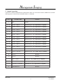
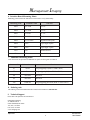
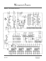
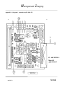
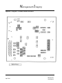
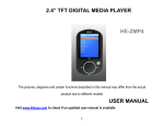
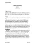
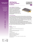
Narragansett Imaging
RS422 Interface Board for FTM1010
IB-1010-422
User Manual
Narragansett Imaging
April 2001
51 Industrial Drive
North Smithfield, RI 02896
Tel: (401) 762-3800
Fax: (401) 767-4407
www.nimaging.com
Narragansett Imaging
Contents
1. Introduction .................................................................................................................................
2. Getting started ..............................................................................................................................
3. DC power supply inputs ...............................................................................................................
4. Mode control ................................................................................................................................
5. Output connections .......................................................................................................................
6. Interface board measuring points .................................................................................................
7. Additional measuring points ........................................................................................................
8. Ordering code ...............................................................................................................................
9. Technical support .........................................................................................................................
3
3
3
3
4
5
5
5
5
Appendix 1. Block diagram IB-1010-422 ........................................................................................ 6
Appendix 2. Mechanical
Diagram 1. Top view IB-1010-422 ............................................................................................... 7
Diagram 2. Bottom view IB-1010-422 ......................................................................................... 8
April 2001
IB-1010-422
User Manual
Narragansett Imaging
1. Introduction
The IB-1010-422 Interface Board is provided as a means to quickly setup and operate the Narragansett Imaging’s FTM1010
OEM camera module. It is not necessarily a component which can be incorporated into an OEM end product as its mechanical configuration and interface are not optimized to this end. The board does provide electromechanical interface to the
FTM1010, RS422 drivers, a basic power supply interface, some simple mode control through mechanical switches and a
connector which permits cabling to a frame grabber.
2. Getting Started
Begin by plugging the FTM1010 board camera into the connector marked X2 on the interface board. The frame grabber
cable can be plugged into connector X5. Cables for Image Technology PCI frame grabbers and Bitflow Roadrunner digital
frame grabbers can be supplied. A dual DC power supply is required and connections are made at the points listed in the
table below. Please refer to the schematic diagram and assembly diagrams contained in appendix A as you read the subsequent sections of this manual.
3. DC Power Supply Inputs
The interface board requires a DC power supply as indicated below. The FTM1010 operating voltages are generated by on
board linear regulators.
P C B P i n ID
Schemat i c l abel
F unct i on
M P1
+15V- IN
+15V DC @ 1A Max
M P2
- 15V- IN
- 15V DC @ 200mA Max
M P3
GN D- IN
Power ground
4. Mode Control
Operating modes of the camera are controlled by toggle switches S3,4. The mode control via toggle switches is enabled
when S5 shorting jumper is in position A-C. S1 and S2 are hard wired so that the output data drivers are enabled and the
oscillator is always enabled.
Sw i t ch R ef
Mode
SW P osi t i on
St at e
F unct i on
S1
OE
Hard wired
Logic 0
Data output enabled
S2
XTAL- EN
Hard wired
Logic 1
O scillator enabled
S3
Vertical binning
UP
Logic 1
Full resolution
DO WN
Logic 0
Vertical binning on
UP
Logic 1
IT control mode*
DO WN
Logic 0
C ontinuous readout
S4
IT control
* During the IT Control mode, an active low integration control pulse can be applied to the camera through connector
X1 pin 1. The schematic shows this input as a label “Lens Contact” and its ground is at X1 pin 2. The input pulse can
be a simple mechanical switch. There is a conditioning circuit following the connector input which will de-bounce the
mechanical contact. The integration control input pulse to the FTM1010 module must be made active high by installing
ZR62 and removing ZR63.
April 2001
3
IB-1010-422
User Manual
Narragansett Imaging
5. Output Connections
Connector X5 contains the RS422 data and synchronization output. It is a 50 Pin SCSI connector (AMP#787169-5) with the
following pin out. Connector mates with AMP #749621-5 or equivalent.
X5 Pin #
25
Schemat i c name
F unct i on
GN D
Ground
24 / 49
D0- FG+ / D0- FG-
Data bit D0 pos. / neg. O utput is RS422 compatible
23 / 48
D1- FG+ / D1- FG-
Data bit D1 pos. / neg. O utput is RS422 compatible
22 / 47
D2- FG+ / D2- FG-
Data bit D2 pos. / neg. O utput is RS422 compatible
21 / 46
D3- FG+ / D3- FG-
Data bit D3 pos. / neg. O utput is RS422 compatible
20 / 45
D4- FG+ / D4- FG-
Data bit D4 pos. / neg. O utput is RS422 compatible
19 / 44
D5- FG+ / D5- FG-
Data bit D5 pos. / neg. O utput is RS422 compatible
18 / 43
D6- FG+ / D6- FG-
Data bit D6 pos. / neg. O utput is RS422 compatible
17 / 42
D7- FG+ / D7- FG-
Data bit D7 pos. / neg. O utput is RS422 compatible
16 / 41
D8- FG+ / D8- FG-
Data bit D8 pos. / neg. O utput is RS422 compatible
15 / 40
D9- FG+ / D9- FG-
Data bit D9 pos. / neg. O utput is RS422 compatible
14 / 39
D10- FG+ / D10- FG-
Data bit D10 pos. / neg. O utput is RS422 compatible
13 / 38
D11- FG+ / D11- FG-
Data bit D11 pos. / neg. O utput is RS422 compatible
10
D12- FG
Reserved
11
D13- FG
Reserved
7 / 32
H- FG+ / H- FG-
H pulse pos. / neg. O utput is RS422 compatible
9 / 34
V- FG+ / V- FG-
V pulse pos. / neg. O utput is RS422 compatible
4 / 29
PC LK - FG+ / PC LK - FG-
Pixelclock pos. / neg. O utput is RS422 compatible
26
C AM- DRIVE- FG
Reserved
March 2001
4
IB-1010-422
User Manual
Narragansett Imaging
6. Interface Board Measuring Points
Measuring points listed in the table below can be used to verify functionality.
Measuri ng poi nt
Schemat i c name
F unct i on
ZMP1
+6V PW R
+6V DC
ZMP2
+5V PW R
+5V DC
ZMP3
- 6V PW R
- 6V DC
ZMP4
- 5V PW R
- 5V DC
ZMP5
IT- C O N TRO L
Integration control pulse
ZMP6
H- 2PC
Scope trigger H pulse
ZMP7
V- 2PC
Scope trigger V pulse
M P9
GN D
Ground reference
M P10
GN D
Ground reference
7. Additional Measuring Points
Coax connections are provided as additional test points for the signals as indicated.
C onnect or ID
Schemat i c name
F unct i on
X3
H- ext.
Scope triggering H (Rout 75 O hm C MO S)
X7
V- ext.
Scope triggering V (Rout 75 O hm C MO S)
X8
Reserved
Reserved
X9
Reserved
Reserved
X10
Pxlclk- ext.
Scope triggering pixel clock (Rout 75 O hm C MO S)
8. Ordering code
The ordering code for the RS422 Interface board for the FTM1010 is IB-1010-422.
9. Technical Support
Please direct all questions and comments to:
Narragansett Imaging
51 Industrial Drive
North Smithfield, RI 02896
Tel: (401) 762-3800
Fax: (401) 767-4407
www.nimaging.com
April 2001
5
IB-1010-422
User Manual
Narragansett Imaging
Appendix 1. Block diagram IB-1010-422
April 2001
IB-1010-422
User Manual
Narragansett Imaging
Appendix 2., Diagram 1. Assemble top IB-1010-422
April 2001
IB-1010-422
User Manual
Narragansett Imaging
Appendix 2. Diagram 2. Assembly bottom IB-1010-422
April 2001
IB-1010-422
User Manual