1
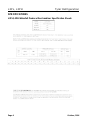
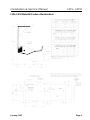
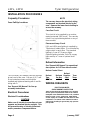
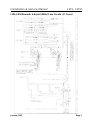
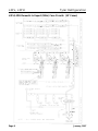
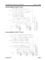
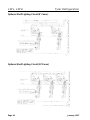
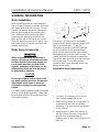
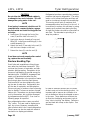
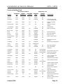
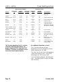
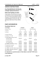
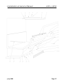
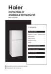
Installation & Service
Manual
L3PL, L3PH
WATERFALL PRODUCE MERCHANDISERS
Medium Temperature Refrigerated Display Cases
This manual has been designed to be used in conjunction with the General
Installation & Service Manual.
Save the Instructions in Both Manuals for Future Reference!!
This merchandiser conforms to the Commercial Refrigeration Manufacturers Association Health and Sanitation standard CRS-S1-96.
PRINTED IN Specifications subject to REPLACES
IN U.S.A.
change without notice. EDITION
1/97
ISSUE
DATE
7/99
Tyler Refrigeration Corporation * Niles, Michigan 49120
PART
NO.
9027537
REV.
B
Installation & Service Manual
L3PL, L3PH
CONTENTS
Page
Specifications
L3PL/L3PH Specification Sheets . . . . . . . . . . . . . . . . . . . . . . . . . . . 4
Pre-Installation Responsibilities . . . . . . . . . . . (See General I&S Manual)
Installation Procedures
Carpentry Procedures . . . . . . . . . . . . . . . . . . . . . . . . . . . . . . . . . 6
Case Pull-Up Locations . . . . . . . . . . . . . . . . . . . . . . . . . . . . . . . . . 6
Electrical Procedures . . . . . . . . . . . . . . . . . . . . . . . . . . . . . . . . . . 6
Plumbing Procedures . . . . . . . . . . . . . . (See General I&S Manual)
Refrigeration Procedures . . . . . . . . . . . (See General I&S Manual)
Defrost Information . . . . . . . . . . . . . . . . . . . . . . . . . . . . . . . . . . . . 6
Defrost Control Chart . . . . . . . . . . . . . . . . . . . . . . . . . . . . . . . . . . . 6
Installation Procedure Check Lists . . . . (See General I&S Manual)
Wiring Diagrams
L3PL/L3PH Domestic & Export (50Hz) Case Circuits . . . . . . . . . . . 7
Canopy Lighting Circuits . . . . . . . . . . . . . . . . . . . . . . . . . . . . . . . . 9
Optional Shelf Lighting Circuits . . . . . . . . . . . . . . . . . . . . . . . . . . 10
Cleaning and Sanitation . . . . . . . . . . . . . . . . . . (See General I&S Manual)
General Information
Mirror Installation . . . . . . . . . . . . . . . . . . . . . . . . . . . . . . . . . . . . . 11
Water Spray Accessories . . . . . . . . . . . . . . . . . . . . . . . . . . . . . . . 11
Produce Handling Tips . . . . . . . . . . . . . . . . . . . . . . . . . . . . . . . . 12
Service Instructions
Preventive Maintenance . . . . . . . . . . . . (See General I&S Manual)
Ballast and Lighting Locations . . . . . . . . . . . . . . . . . . . . . . . . . . 15
Parts Information
Operational Parts List . . . . . . . . . . . . . . . . . . . . . . . . . . . . . . . . . . 15
Cladding and Trim Parts List . . . . . . . . . . . . . . . . . . . . . . . . . . . . . 16
TYLER Warranty . . . . . . . . . . . . . . . . . . . . . . . (See General I&S Manual)
The following Medium Temperature Waterfall Produce Merchandiser models are covered
in this manual:
MODELS
DESCRIPTION
L3PL
8’ & 12’ WATERFALL LOW FRONT PRODUCE MERCHANDISER
L3PH
8’ & 12’ WATERFALL HIGH FRONT PRODUCE MERCHANDISER
January, 1997
Page 3
L3PL, L3PH
Tyler Refrigeration
SPECIFICATIONS
L3PL/L3PH Waterfall Produce Merchandiser Specification Sheets
Page 4
October, 1996
Installation & Service Manual
L3PL, L3PH
L3PL/L3PH Waterfall Produce Merchandiser
January, 1997
Page 5
L3PL, L3PH
Tyler Refrigeration
INSTALLATION PROCEDURES
Carpentry Procedures
Case Pull-Up Locations
NOTE
The raceway houses the electrical wiring,
components and terminal blocks for the
case. Remove the lower front cladding to
access the raceway.
Case Fan Circuit
This circuit is to be supplied by an uninterrupted, protected 120V circuit. The case fan
circuit is not cycled during defrost on any of
these models.
Fluorescent Lamp Circuit
L3PL and L3PH case lighting is supplied by
T-8 electronic ballast lights. It is controlled by
a light switch in each case. The standard
lighting is 1-row of T-8 canopy lights.
Optional lighting includes 2-row T-8 canopy
lights and up to 3 rows of optional shelf
lights.
Defrost Information
See “General I&S Manual” for operational
descriptions for Off Time defrost control.
Defrost Control Chart
The L3PL and L3PH models have four pull-ups
at each end of the case. Pull-ups A, B, C and
D are located as shown and should be
installed and tightened starting with A and finishing with D.
See “General I&S Manual” for line-up
assembly instructions.
Electrical Procedures
Electrical Considerations
CAUTION
Make sure all electrical connections at components and terminal blocks are tight. This
will prevent burning of electrical terminals
and/or premature component failure.
Page 6
Defrost
Type
Off Time
Defrost
Defrosts Duration
Per Day
(Min)
3-4
40
Term.
Temp.
-----
WIRING DIAGRAMS
ELECTRICIAN NOTE OVERCURRENT PROTECTION
120V circuits should be protected by 15 or 20 Amp
devices per the requirements noted on the cabinet
nameplate or the National Electrical Code, Canadian
Electrical Code - Part 1, Section 28. 208V defrost
circuits employ No. 12 AWG field wire leads for field
connections. On remote cases intended for end to
end line-ups, bonding for ground may rely upon the
pull-up bolts.
January, 1997
Installation & Service Manual
L3PL, L3PH
L3PL/L3PH Domestic & Export (50Hz) Case Circuits (8’ Cases)
January, 1997
Page 7
L3PL, L3PH
Tyler Refrigeration
L3PL/L3PH Domestic & Export (50Hz) Case Circuits (12’ Cases)
Page 8
January, 1997
Installation & Service Manual
L3PL, L3PH
Canopy Lighting Circuits (8’ Cases)
Canopy Lighting Circuits (12’ Cases)
January, 1997
Page 9
L3PL, L3PH
Tyler Refrigeration
Optional Shelf Lighting Circuit (8’ Cases)
Optional Shelf Lighting Circuit (12’Cases)
Page 10
January, 1997
Installation & Service Manual
L3PL, L3PH
GENERAL INFORMATION
Mirror Installation
When installing mirrors you must be aware
that on longer line-ups it is possible to end up
with a gap at the end of the line-up. To help
prevent this, leave a gap at the starting end
that can be covered by the stainless steel
trim. Additional mirror positioning adjustments may be required to make sure the
gaps at each end of the line-up don’t show
when the stainless steel trim is in place. Also
make sure all mirrors have a good tight seal
between each mirror.
Water Spray Accessories
WARNING
When using water spray accessories it
may be necessary to install approved antibackflow devices in the water supply line.
Local codes should be checked in this
regards. Installation of this device is the
responsibility of the end user and would
be performed by plumbers.
The spring coil spray hose or retractable
spray hose are the two manual systems available for produce cases. To use the
retractable spray hose, pull the nozzle and
hose out smoothly to the desired length.
When the reel rachet sounds, let the hose
back against the rachet to hold it in place. To
rewind, pull hose out slightly to release the
reel rachet, then guide the hose back into the
front of the case. Do not allow hose to
rewind by itself. Hose jamming and/or reel
damge could result.
Retractable Hose Replacement
CAUTION
Do not spray lighted shelves when using
any water spray accessories. Moisture on
light fixtures could cause an electrical
short and/or damage the case operating
system.
The water supply pressure should not exceed
45 lb to assure proper operation. Water supply pressures above 45 lb should use a pressure reducing valve.
1. Pull hose (1) completely out of front of
case (2) and engage reel rachet.
2. Fasten locking pliers on the reel edge (3)
to prevent the reel from accidentally
rewinding. The reel spring is fully wound
in this position.
3. Remove hose (1) from hose clamps on
the reel (3) and disconnect hose end fitting (4) from swivel assembly (5).
Remove hose (1) from reel (3) and front of
case (2).
October, 1996
Page 11
L3PL, L3PH
CAUTION
Do not allow the reel to unwind suddenly
or attempt to turn reel clockwise. This will
damage the spring motor in the reel.
NOTE
If reel spring is unwound, wind the reel 19
complete turns counterclockwise, engage
the reel rachet and install locking pliers on
reel edge.
4. Insert hose (1) through the front of the
case (2) and the hole in the reel (3).
Tyler Refrigeration
Refrigerated produce cases displays produce
products that require refrigeration. The refrigeration coil is below the display and fans are
used to circulate air through the case display.
This moving air will pick up moisture from
unwrapped produce and carry it to the coil. It
is necessary to replace this moisture by using
a water spray several times during the day.
At night the produce should be covered wih a
wet cloth. The alternate to sprinkling is to
wrap the produce.
5. Apply pipe dope to threads of hose end
fitting (4). Install hose end fitting (4) in the
swivel assembly (5).
6. Attach the hose (1) securely to the reel (3)
with the hose clamps on the reel.
7. Retract the hose (1) onto the reel (3).
NOTE
If reel does not work properly after rewinding, replace the reel assembly.
Produce Handling Tips
Fresh fruits and vegetable are living things,
even after they have been harvested. They
continue the process of respiration and transpiration after harvesting. Respiration is the
process of self feeding to provide energy for
maintaining life. (EXAMPLE: Asparagus and
sweet corn generate heat after they are
picked.) Transpiration is the process of water
loss through vapor from the plant tissues.
Post-harvest life can be maintained by slowing the rate of water loss. Refrigeration lowers the rate of respiration and transpiration.
Store most types of produce close to freezing
prior to display. There are a number of explanations (ex. Cucumbers can be kept relatively
cool by themselves, but could be damaged
by temperatures below 40°F). See chart on
following pages for specifics.
Non-refrigerated produce cases are called
“Dry” cases. They are used to display potatoes, dry onions, bananas, avocados and
other products which don’t need refrigeration.
These cases can also be used with a bed of
cracked ice to display perishables.
Page 12
In order to maintain case air flow, the return
air duct must not be blocked by product. An
important aid to improve air circulation is to
use air deflectors below the elevated screens
in the case. These deflectors will direct the
air flow into the display and prevent cool air
from “short circuiting” the display. Deflectors
are furnished with hump screen option. See
illustration.
January, 1997
Installation & Service Manual
L3PL, L3PH
Produce Handling Chart
Ideal Storage Conditions
Produce
Temperature
Relative
(°F)
Humidity (%)
Display Rack Care
Sell Quickly
(1-2 days)
Refrigerate
(40°F)
Sprinkle
with Water
Special Notes
Avoid bruising
Apples
30-32
85-95
Helpful
No advantage
Apricots
31-32
85-90
Yes
Helpful
No
Asparagus
32-36
90-95
Yes
Profitable
No
Trim butts and stand
in ice or shallow water
Avocados
40-55
85-90
Yes
No
No
Display on padded
surface
Bananas, Ripe
56-58
85-90
Yes
No
No
Display on padded
surface
For Ripening
58-68
90-95
No
No
Avoid bruising
Beans, Lima
32-40
85-90
Yes
Profitable
No
Shake up to aerate
Beans, Snap
40-45
90-95
Yes
Profitable
Yes
Beets
32
85-95
Yes
Profitable
Yes
Moisten roots only
Berries
31-32
90-95
Yes
Helpful
No
Keep well ventilated
Broccoli
32-35
90-95
Yes
Profitable
Yes
Keep out of sun
Brussel Sprouts
Yes
Remove yellow leaves
32-35
90-95
Profitable
Yes
Cabbage
32
90-95
Helpful
Yes
Carrots
32
90-95
Profitable
Yes
Moisten roots only of
bunches
Cauliflower
32
90-95
Yes
Profitable
Yes
Sprinkle only if refrigerated
Celery
31-32
90-95
Yes
Profitable Yes
Cherries
31-32
90-95
Yes
Helpful
No
Keep well ventilated
Corn, Sweet
31-32
90-95
Yes
Profitable
Yes
Keep cold to keep
sweetness
Cucumbers
45-50
85-90
Yes
No
No advantage
Eggplants
45-50
85-90
Yes
Grapefruit
50-60
85-90
Grapes
30-32
85-95
Honeydews
45-50
85-90
Lemons
38-40
85-90
Lettuce
32
90-95
Limes
48-50
85-90
Mushrooms
32-35
80-90
Muskmelons
32-35
85-90
Onions, Dry
32
65-70
Onions, Green
Yes
No
No advantage
Do not bruise, keep on ice
Helpful
No advantage
Remove decayed fruit
Helpful
No
Keep well ventilated
Helpful
No
Cover cut melons with
transparent film
Helpful
Yes
Sprinkling may be helpful
Profitable
Yes
Avoid soaking with water
Helpful
No advantage
Yes
Helpful
No
Handle carefully, keep dry
Yes
Helpful
No
Cover cut melons with
transparent film
No
No
Remove loose wrappers,
keep dry
Yes
32
90-95
Profitable
Yes
Oranges
34-38
85-90
Helpful
No advantage
Parsnips
32
90-95
Helpful
Yes
Moisten roots only
Peaches, Ripe
31-32
90
Yes
Helpful
No
Ripen at room temperature
before storage
Pears
29-31
90-95
Yes
Helpful
No
Display in single or double
layer on pads
October, 1996
Yes
Keep well ventilated
Remove decayed fruit
Page 13
L3PL, L3PH
Tyler Refrigeration
Ideal Storage Conditions
Produce
Temperature
Relative
(°F)
Humidity (%)
Peas, Green
Display Rack Care
Sell Quickly
(1-2 days)
Refrigerate
(40°F)
Sprinkle
with Water
Special Notes
32
90-95
Yes
Profitable
Yes
Peppers
45-50
90-95
Yes
Profitable
Yes
Pineapples, Ripe
45-55
85-90
Yes
No
No
Remove decayed fruit
Plums
31-32
90-95
Yes
Helpful
No
Remove decayed fruit
Potatoes
40-50
85-90
No
No
Keep out of sun
Radishes
32
90-95
Yes
Profitable
Yes
Keep water off tops,
avoid tight packing
Rhubarb
32
90-95
Yes
Profitable
No
Trim thin slice off stems
and stand in cold water
85-95
Yes
Helpful
Yes
No
No
Yes
Profitable
Yes
Keep ventilated
No
No
Keep ventilated
Squash, Summer 40-50
Winter & Pmpkns 50-55
Spinach
Sweet Potatoes
Tangerines
50-75
32
90-95
55-60
85-90
Shake up to aerate,
keep cold
32
85-90
Yes
Profitable
Yes
Remove decayed fruit
Tomatoes, Ripe
45-50
85-90
Yes
Helpful
No
Sell quickly, refrigerate
to hold
Tomatoes, Green
55-70
85-90
No
No
Ripen in back room,
sort frequently
32
90-95
Profitable
Yes
Sprinkle roots only
40-45
80-85
Helpful
No
Cover cut melons with
transparent film
Turnips
Watermelons
The “Produce Handling Chart” is courtesy
of Produce Marketing Association, Inc.,
Newark, Delaware 19711, from their 1973
Yearbook. This book is published as a service to the Fresh Produce Industry.
For additional information, consult:
“The Commercial Storage of Fruits,
Vegetables, and Florist and Nursery Stocks”,
USDA Handbook No. 66, 1968.
“The Shelf Life of Fresh Fruits and Vegetables
- Retail Store Display Cases”, USDA HT&S
Office Report No. 247, October 1951.
“Fresh Fruits and Vegetables - Handling and
Care”, Corporate Extension Service, Michigan
State University.
Page 14
October, 1996
Installation & Service Manual
L3PL, L3PH
SERVICE INSTRUCTIONS
See “General I&S Manual” for T-8 lamp, and
ballast, fan blade and motor, and color band
and bumper replacement instructions.
Ballast and Lighting Locations
All light ballasts are located under the canopy
and mounted on the top of the canopy light fixture. This includes remote ballasts for optional
shelf lights. The canopy light(s) are under the
canopy light fixture in the top of the case. The
optional shelf lights are mounted in separate
light fixtures under the front of each shelf section.
PARTS INFORMATION
Operational Parts List
Case Usage
Domestic
Export
Electrical Circuit
115 Volt 60 Hertz
220 Volt 50 Hertz
Case Size
8’
12’
8’
12’
Fan Motor
5125532
5125532
5202539
5202539
5 Watt
5 Watt
7.5 Watt
7.5 Watt
Fan Motor Brackets
5962269
5962269
5962269
5962269
Fan Blades (7” 30° 5B)
5223370
5223370
5223370
5223370
T-8 Lamp Ballast (canopy & shelf)
(canopy)(2 lamp)
5991029
----
9028437
----
(canopy)(3 lamp)
----
5991030
----
9028438
(canopy)(4 lamp)
5966635
----
9028439
----
(opt. shelf)(3 lamp)
5991030
5991030
9028438
9028438
Opt. 800MA Lamp Ballast (canopy)
5049140
5049140
5204859
5204859
T-8 Lampholder (canopy)
5232279
5232279
5232279
5232279
T-8 Lampholder (shelf)
5092414
5092414
5092414
5092414
Opt. 800MA Lampholder (telescoping) 5614628
5614628
5614628
5614628
Opt. 800MA Lampholder (stationary)
5614629
5614629
5614629
5614629
Light Switch (SPST)
5100565
5100565
5100565
5100565
For information on operational parts not listed above contact the TYLER Service
Parts Department.
January, 1997
Page 15
L3PL, L3PH
Tyler Refrigeration
Cladding and Trim Parts List
Item Description
L3PL
L3PH
8’
12’
8’
12’
1
Screw
5183536(4)
5183536(6)
5183536(4)
5183536(6)
2
Screw
5183536(4)
5183536(6)
5183536(4)
5183536(6)
3
Hood Close-off
9026069
9026070
9026069
9026070
4
Screw (per end cover)
5183536(4)
5183536(4)
5183536(4)
5183536(4)
5
End Cover
9026103(2)
9026103(2)
9026103(2)
9026103(2)
6
Canopy Hood, Painted
9025223
9025224
9025223
9025224
7
Canopy Hood Backer, Painted
9025983
9025983
9025983
9025983
8
Bumper Retainer / Handrail
9
Color Band, Painted
9023798
9023800
9023798
9023800
10
Color Band Backer, Painted
9040223
9040223
9040223
9040223
11
Handrail Backer, Pntd.
9025316
9025316
9025316
9025316
12
Bumper Backer
-----------------
color per order
-----------------
13
Bumper End Trim
-----------------
color per order
-----------------
14
Bumper
-----------------
color per order
-----------------
15
Upr. Frt. Cladding, Painted
----
----
9025479
9025480
16
Rivet
----
----
5104702(4)
5104702(6)
17
Screw, Shoulder
9025833(6)
9025833(8)
9025833(6)
9025833(8)
18
Lwr. Frt. Cladding, Painted
9025477
9025478
9025477
9025478
19
Kickplate
20
Kickplate Backer
21
-----------------
-----------------
color per order
color per order
-----------------
-----------------
9041790
9041790
9041790
9041790
Screw
5183536(6)
5183536(8)
5183536(6)
5183536(8)
22
Kickplate Support
9041329(3)
9041329(4)
9041329(3)
9041329(4)
23
Screw
5183536(6)
5183536(8)
5183536(6)
5183536(8)
24
Raceway
9025127
9025128
9025127
9025128
25
LH End Close-off, Painted
9022459
9022459
9022459
9022459
RH End Close-off, Painted
9022466
9022466
9022466
9022466
Horizontal Joint Trim
9025959
9025959
9025959
9025959
26
Page 16
July, 1999
Installation & Service Manual
July, 1999
L3PL, L3PH
Page 17