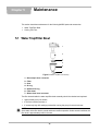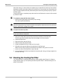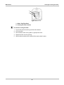
1
Flexible Gas Analyzer
User Manual
February 2011
ZEEMS306A Rev. F
Trademarks Acknowledgements
Snap-on, Scanner, Fast-Track, and MODIS are trademarks of Snap-on Incorporated.
All other marks are trademarks or registered trademarks of their respective holders.
Copyright Information
©2011 Snap-on Incorporated
All rights reserved.
Disclaimer
The information, specifications and illustrations in this manual are based on the latest information available at the
time of printing.
Snap-on reserves the right to make changes at any time without notice.
Visit our Web site at:
http://diagnostics.snapon.com
For Technical Assistance Call:
1-800-424-7226
ii
Safety Information
For your own safety and the safety of others, and to prevent damage to the equipment and
vehicles upon which it is used, it is important that the accompanying Important Safety Instructions
be read and understood by all persons operating, or coming into contact with, the equipment. We
suggest you store a copy the book near the unit in sight of the operator
This product is intended for use by properly trained and skilled professional automotive
technicians. The safety messages presented throughout this manual are reminders to the
operator to exercise extreme care when using this test instrument.
There are many variations in procedures, techniques, tools, and parts for servicing vehicles, as
well as in the skill of the individual doing the work. Because of the vast number of test applications
and variations in the products that can be tested with this instrument, we cannot possibly
anticipate or provide advice or safety messages to cover every situation. It is the automotive
technician’s responsibility to be knowledgeable of the system being tested. It is essential to use
proper service methods and test procedures. It is important to perform tests in an appropriate and
acceptable manner that does not endanger your safety, the safety of others in the work area, the
equipment being used, or the vehicle being tested.
It is assumed that the operator has a thorough understanding of vehicle systems before using this
product. Understanding of these system principles and operating theories is necessary for
competent, safe and accurate use of this instrument.
Before using the equipment, always refer to and follow the safety messages and applicable test
procedures provided by the manufacturer of the vehicle or equipment being tested. Use the
equipment only as described in this manual.
Read, understand and follow all safety messages and instructions in this manual, the
accompanying safety manual, and on the test equipment.
Safety Message Conventions
Safety messages are provided to help prevent personal injury and equipment damage. All safety
messages are introduced by a signal word indicating the hazard level.
! DANGER
Indicates an imminently hazardous situation which, if not avoided, will result in death or serious
injury to the operator or to bystanders.
! WARNING
Indicates a potentially hazardous situation which, if not avoided, could result in death or serious
injury to the operator or to bystanders.
! CAUTION
Indicates a potentially hazardous situation which, if not avoided, may result in moderate or minor
injury to the operator or to bystanders.
iii
Safety Information
Important Safety Instructions
Safety messages contain three different type styles.
• Normal type states the hazard.
• Bold type states how to avoid the hazard.
• Italic type states the possible consequences of not avoiding the hazard.
An icon, when present, gives a graphical description of the potential hazard.
Example:
! WARNING
Risk of unexpected vehicle movement.
• Block drive wheels before performing a test with engine running.
A moving vehicle can cause injury.
Important Safety Instructions
For a complete list of safety messages, refer to the accompanying safety manual.
SAVE THESE INSTRUCTIONS
iv
Table of Contents
Safety Information ..................................................................................................................... iii
Safety Message Conventions....................................................................................................... iii
Important Safety Instructions........................................................................................................iv
Chapter 1: Using This Manual ................................................................................................... 1
Bold Text ................................................................................................................................ 1
Symbols ................................................................................................................................. 1
Terminology ........................................................................................................................... 2
Note and Important Messages ............................................................................................... 2
Procedures............................................................................................................................. 2
Chapter 2: Introduction.............................................................................................................. 4
Chapter 3: Navigation .............................................................................................................. 11
Upper Toolbar ...................................................................................................................... 11
Main Body ............................................................................................................................ 13
Lower Toolbar ...................................................................................................................... 14
Chapter 4: Operations.............................................................................................................. 16
RPM ..................................................................................................................................... 18
Graph ................................................................................................................................... 18
Digital ................................................................................................................................... 19
Digital and Graph ................................................................................................................. 19
Digital and Bars.................................................................................................................... 20
Toggle Pump........................................................................................................................ 21
Zero Calibration ................................................................................................................... 21
Leak Check .......................................................................................................................... 22
Gas Bottle Calibration .......................................................................................................... 24
Trace Number ...................................................................................................................... 28
Test ...................................................................................................................................... 28
Loading Saved Files ............................................................................................................ 30
Editing Presets ..................................................................................................................... 30
Deleting Presets................................................................................................................... 32
Copying and Moving Presets ............................................................................................... 33
Selecting Multiple Files ........................................................................................................ 33
Gas Values .......................................................................................................................... 34
Install NO Cell ...................................................................................................................... 36
Diagnostics .......................................................................................................................... 36
Chapter 5: Maintenance ........................................................................................................... 38
Index .......................................................................................................................................... 41
v
Chapter 1
Using This Manual
This manual contains tool usage instructions.
Some of the illustrations shown in this manual may contain modules and optional equipment that
are not included on your system. Contact a sales representative for availability of other modules
and optional equipment.
1.1 Conventions
1.1.1 Bold Text
Bold emphasis is used in procedures to highlight selectable items such as buttons and menu
options.
Example:
• Press the Y/a button.
1.1.2 Symbols
The following types of arrows are used.
The “greater than” arrow (>) indicates an abbreviated set of selection instructions.
Example:
• Select Utilities > Tool Setup > Date.
The above statement abbreviates the following procedure:
1. Navigate to the Utilities button.
2. Use the Thumb Pad to navigate to and highlight the Tool Setup submenu.
3. Use the Thumb Pad to navigate to and highlight the Date option from the submenu.
4. Press Y/a to confirm the selection.
The solid arrows (e, c, d, b) are navigational instructions referring to the four directions of the
Thumb Pad.
Example:
• Press the down d arrow.
1
Using This Manual
Conventions
1.1.3 Terminology
The term “select” means highlighting a button or menu item using the Thumb Pad and pressing
the Y/a button to confirm the selection.
Example:
• Select Reset.
The above statement abbreviates the following procedure:
1. Navigate to and highlight the Reset button.
2. Press the Y/a button.
1.1.4 Note and Important Messages
The following messages are used.
Note
A NOTE provides helpful information such as additional explanations, tips, and comments.
Example:
i
NOTE:
For additional information refer to...
Important
IMPORTANT indicates a situation which, if not avoided, may result in damage to the test
equipment or vehicle.
Example:
IMPORTANT:
Do not force the CompactFlash® card into the slot.
1.1.5 Procedures
An arrow icon indicates a procedure.
Example:
z
To change screen views:
1. Select View.
The drop-down menu displays.
2. Select an option from the menu.
The screen layout changes to the format you selected.
2
Using This Manual
Additional Manuals
1.2 Additional Manuals
Tools that work in conjunction with various hardware and software modules have separate
manuals available for each of the modules.
1.3 Tool Help
Your unit has Tool Help containing reference and procedural information found in this and other
tool related user’s manuals. From the main menu, access Tool Help on the Utilities menu.
3
Introduction
Chapter 2
The Snap-on Flexible Gas Analyzer (FGA) (Figure 2-1) is a self-contained, battery operated unit
that connects to the MODIS™ unit and uses the MODIS™ Gases software mode for emissions
testing and data storage.
Figure 2-1 Flexible Gas Analyzer (FGA) unit
2.1 Power Sources
The FGA unit uses a long-life, internal, rechargeable battery and supports the three external
power sources illustrated below (Figure 2-2).
1
2
3
Figure 2-2 Three of the four FGA unit power sources
1— 12VDC source with cigarette lighter adapter
2— 12VDC direct from vehicle battery
3— External 13.2VDC high output power supply
Also charges the internal battery
4
Introduction
Internal Cooling Fan
2.2 Internal Cooling Fan
The FGA unit’s internal cooling fan is automatically controlled by a microprocessor inside the unit.
The fan runs when the internal unit temperature reaches 100 degrees Fahrenheit, and turns off
when the internal unit temperature falls below 90 degrees Fahrenheit. No user action is required
to operate the fan.
IMPORTANT:
Do not block the cooling fan vent (Figure 2-3). The internal cooling fan needs a free-flowing air
supply to operate properly.
Figure 2-3 Cooling Fan Vent on side of FGA unit
A foam cooling fan filter (Figure 2-4) is covered by a plastic grill and is located behind the water
trap/filter bowl. Periodic maintenance is required.
For cleaning procedures, refer to “Cleaning the Cooling Fan Filter” on page 39.
1
2
Figure 2-4 Side of FGA unit
1— Water Trap/Filter Bowl
2— Cooling Fan Filter
2.3 The FGA Pump
An internal pump is used to clear water and residual gases from the water trap/filter bowl.
For a more detailed discussion of the FGA pump, refer to “Toggle Pump” on page 21.
5
Introduction
Unit Software
2.4 Unit Software
The FGA unit software is included in the MODIS™ 3.2 (and newer) system software.
i
NOTE:
If the Gases button displays on the MODIS™ main menu, the FGA software is installed on your
MODIS™ unit.
z
To verify that the FGA software is installed:
1. Select Utilities > System Info.
The System Info screen displays (Figure 2-5).
Figure 2-5 Sample System Info screen
2. Make sure you are running Software Revision: 1.2.0 build 266 or newer.
3. Press N/X to return to the main menu.
2.5 Assembling the FGA Unit
Required Tools:
• 1/2” open end wrench
• 9/16” open end wrench
6
Introduction
z
Assembling the FGA Unit
To assemble the FGA unit:
1. Connect the short clear hose (included with the FGA unit, but not pictured) to the Exhaust
quick coupler outlet on the water trap/filter bowl end of the analyzer (Figure 2-6).
2
1
Figure 2-6 Side of FGA unit
1— Water Trap/Filter Bowl
2— Exhaust Outlet
i
NOTE:
If the Exhaust hose is not connected, the analyzer will automatically shut down.
Refer to the “Equipment Overview” section in the Flexible Gas Analyzer (FGA) Operating
Instructions Manual for more detailed information about the hoses.
2. Install the Exhaust Sample Flex Probe (Figure 2-7) into the Exhaust Sample Hose Handle
using 1/2” and 9/16” open end wrenches.
1
2
Figure 2-7 Exhaust Sample Flex Probe assembly
1— Exhaust Sample Hose Handle
2— Exhaust Sample Probe
Make sure the probe is tightened securely.
3. Remove the Leak Check Probe Adapter Cap (Figure 2-8) and store it in a safe place.
7
Introduction
Assembling the FGA Unit
1
2
Figure 2-8 Assembled Exhaust Sample Probe
1— Exhaust Sample Probe
2— Leak Check Adapter cap
4. Connect the black sample hose to the quick coupler next to the sample filter bowl.
5. Connect the long yellow 13.2V power cord (Figure 2-9) to the POWER IN connection on the
cable connection panel (Figure 2-10).
1
2
Figure 2-9 13.2V Power Cord and DC Power Supply
1— Yellow 13.2V Power Cord
2— 13.2V DC Power Supply
The 13.2V power cable has a large black female connector on one end, and a small silver
male connector on the other end. The silver male connector end must be threaded onto the
Power In connector to secure it to the panel.
The cable connection panel is on the opposite end of the analyzer from the filter bowl
(Figure 2-10).
Figure 2-10 Power In connector on side of FGA unit
8
Introduction
Charging the FGA Unit Battery
6. Connect the other end of the Power In cable to the black male connector on the 13.2V DC
power supply.
i
NOTE:
The DC power supply has an On/Off switch and a green LED to indicate when charging is active.
7. Attach the AC power cord to the other end of the power supply (Figure 2-11).
1
2
Figure 2-11 13.2V Power Cord and DC Power Supply
1— 13.2V DC Power Supply
2— AC Power Cord Plugs to Wall Socket
2.6 Charging the FGA Unit Battery
Before using the Flexible Gas Analyzer for the first time, or when the analyzer has not been used
for several weeks, allow the internal battery to charge for at least twenty-four hours.
Be aware of the following:
• The internal battery will not charge if the ambient temperature inside the FGA unit is above
145 ° F (65 ° C).
• The FGA unit internal battery will not over-charge.
The FGA unit uses an automatic rate controlled battery charger which allows the unit to
remain connected to the charger indefinitely without causing damage to the unit or battery.
• The internal battery remain charged for about 2–4 months without use.
z
To charge the internal battery:
1. Plug one end of the battery power adapter (Figure 2-10) into an 115V AC outlet, and the other
end into the Power In socket on the FGA unit connection panel (Figure 2-12).
1
2
3
Figure 2-12 Battery Power Adapter
1— 13.2V Power Cord plugs to unit
2— 13.2V DC Power Supply
3— AC Power Cord plugs to wall socket
9
Introduction
Connecting the FGA Unit to the MODIS™ Unit
2. Turn on the charger using the switch on the DC power supply.
A green LED lights to indicate charging is active.
3. Let the battery charge for twenty-four hours before using the FGA unit.
2.7 Connecting the FGA Unit to the MODIS™ Unit
The following section covers the steps for connecting the FGA unit to the MODIS™ unit.
z
To connect the units:
1. Connect the long serial communications cable (provided with your FGA unit) to the connector
labeled RS232 IN on the connection panel (Figure 2-13).
IMPORTANT:
DO NOT install this cable into the RS232 OUT.
Figure 2-13 RS232 IN serial port
2. Secure the cable with the thumbscrews.
IMPORTANT:
DO NOT overtighten the thumbscrews.
3. Connect the other end of the long serial communications cable to your MODIS™ serial
communications port located in the center of the top of the MODIS™ unit (Figure 2-14).
Figure 2-14 MODIS™ Serial communications port
10
Navigation
Chapter 3
This section provides navigation information for details about the MODIS™ Gases software. For
more detailed information on how to navigate through the MODIS™ unit, refer to the MODIS™
Display User Manual.
3.1 Screen Layout
MODIS™ Gases test screen has four sections (Figure 3-1).
•
•
•
•
Upper Toolbar
Trace Status Area
Main Body
Lower Toolbar
1
2
3
4
Figure 3-1 Sample Gases test screen
1— Upper Toolbar
2— Trace Status Area
3— Main Body
4— Lower Toolbar
3.1.1 Upper Toolbar
The upper toolbar (Figure 3-2 and Figure 3-3) may contain the controls described in Table 3-1.
Available buttons and controls vary depending on the active mode and stage of operation.
11
Navigation
Screen Layout
Figure 3-2 Sample “Live” Upper toolbar
Figure 3-3 Sample “Paused” Upper toolbar
Table 3-1 Upper toolbar controls
Name
Button
Description
View
Changes the way data displays
Pause
Stops the collection of data to allow for
reviewing buffered data
Play
Resumes collection of data following a
pause
Review
Adjusts how the paused data scrolls
on-screen for reviewing
Cursors
Makes digital amplitude, frequency, and
time measurements
Reset
Clears the minimum and maximumdata for
all digital gauges
Save
Stores data and settings in memory
Print
Prints the displayed screen
Tools
Changes the way information appears
on-screen
Data Buffer
Located just below the upper toolbar buttons, this indicator shows data collection activity when the
screen is live and frame position and numbering information when the screen is paused
(Figure 3-4). The Data Buffer cannot be highlighted or selected.
1
2
Figure 3-4 Sample Data Buffer
1— Pause button
2— Data Buffer
When the screen is paused, the Position Indicator displays the current frame number and the
amount of data on the screen relative to the total data capture. The number of the first frame
collected is displayed to the left of the Position Indicator. The number of the last frame is displayed
to the right of the Position Indicator (Figure 3-5).
12
Navigation
Screen Layout
2
1
Figure 3-5 Sample Scroll Control with Position Indicator
1— Run button
2— Position Indicator
Review Button
The Review button is used in conjunction with the arrow buttons to review data when the screen
is paused.
• Use the right c and left e arrows to review data one frame at a time.
• Use the up b and down d arrows to review data a fraction of a frame at a time when possible.
z
To manually review data:
1. Select the Pause button.
2. Select the Review button.
3. Press the arrow buttons as appropriate to manually review paused data.
The Review button menu lets you change data scrolling of the paused screen from manual scroll
to automatic scroll.
z
To automatically scroll paused data:
1. With the Review button selected, press Ya again to display the menu of scroll options.
2. Select an option from the Review menu.
– Manual Scroll is the default mode that lets you scroll the paused data on-screen using
the arrow buttons.
– Auto Scroll Fast automatically scrolls the paused data on-screen at full-speed.
– Auto Scroll Slow automatically scrolls the paused data on-screen at half-speed.
3.1.2 Main Body
The main body of the MODIS™ Gases test screens (Figure 3-6) may contain the following:
•
•
•
•
•
Trace status information
Digital or graphical test results
Saved data
Cursors
Confirmation messages
13
Navigation
Screen Layout
1
2
Figure 3-6 Sample Main Body screen
1— Trace Status Area
2— Main Body
Trace Status Area
Trace status information displays along the top of the test screen to indicate scales, units, gas
selection, and whether each available trace is on or off (Figure 3-7).
Figure 3-7 Sample Trace status information
3.1.3 Lower Toolbar
The lower toolbar (Figure 3-8) may contain the controls described in Table 3-2. Available buttons
and controls vary depending on the active mode and stage of operation.
1
2
3
4
Figure 3-8 Sample lower toolbar
1— Trace number
2— Test
3— Scale
4— Signal Zero Offset
14
Navigation
Selections
Table 3-2 Lower toolbar controls
Name
z
Button
Description
Trace number
Selects which trace to adjust
Test
Displays the current test chosen for the
selected channel
Scale
Displays the current scale and units for the
selected channel
Signal Zero Offset
Moves the zero (0) position up or down
within the test display area for the selected
channel
Sweep
Sets the amount of time data takes to move
across the screen from left to right
To move between the upper and lower toolbars:
• Press the down d arrow to move to the lower toolbar.
• Press the up b arrow to move to the upper toolbar.
• When Easy Scroll is active, press the N/X button to move to the upper toolbar. Refer to the
MODIS™ Display User Manual for more Easy Scroll information.
3.2 Selections
Refer to your MODIS™ Display User Manual for information and procedures.
15
Chapter 4
Operations
The following sections describe how to operate the MODIS™ Gases software.
4.1 Starting MODIS™ GASES
The FGA unit does not have an On/Off switch. The FGA unit is activated through communication
with the Gases software installed on your MODIS™ display unit.
i
NOTE:
If the FGA unit is not properly connected to your MODIS™ unit, the Gases mode will not function.
The MODIS™ Gases menu lets you select display, calibration, and preset options.
z
To start the Gases software:
1. Connect the FGA unit to your MODIS™ unit using the serial communications cable. See
“Connecting the FGA Unit to the MODIS™ Unit” on page 10 for details.
2. Select Gases > Graph/Digital (Figure 4-1).
Figure 4-1 Sample GASES button and menu
The analyzer automatically powers on and warms up. Before the FGA unit begins to operate,
the pump starts and performs a purge, followed by an automatic zero calibration.
3. Follow the on-screen instruction to continue (Figure 4-2).
16
Operations
Changing the Data Display
Figure 4-2 Sample startup calibration instruction
The Gases test screen displays at the end of the zero calibration process (Figure 4-4).
Figure 4-3 Sample Gases test screen
4.2 Changing the Data Display
The View menu lets you change the format of the data displays on the MODIS™ screen. Five View
options are available:
•
•
•
•
•
z
RPM
Graph
Digital
Digital and Graph
Digital and Bars
To change screen views:
1. Select View.
The drop-down menu displays (Figure 4-4).
Figure 4-4 Sample View menu option
17
Operations
Changing the Data Display
2. Select a View option from the menu.
The screen changes based on your selection.
4.2.1 RPM
Selecting the RPM option displays the RPM field above the trace status area (Figure 4-5).
Figure 4-5 Sample RPM field
4.2.2 Graph
The Graph option displays a line graph with a gas test marker displayed to the right of the
corresponding trace line (Figure 4-6). The marker indicates the zero position of the trace.
Figure 4-6 Sample Gas Test Markers
18
Operations
Changing the Data Display
4.2.3 Digital
The Digital option displays a screen divided into six sections (Figure 4-7). Each section serves as
a gauge for one of the six available traces. If a Trace number is set to not display, the designated
section will appear empty. Refer to “Trace Number” on page 28 for more information about Trace
number settings.
Figure 4-7 Sample Digital screen
4.2.4 Digital and Graph
The Digital and Graph option displays digital test data at the top of the screen and line graph data
below it (Figure 4-8).
1
2
Figure 4-8 Sample Digital and Graph screen
1— Digital Data
2— Line Graph Data
19
Operations
Changing the Setup
4.2.5 Digital and Bars
The Digital and Bars option displays digital test data at the top of the screen and bar graph data
below it (Figure 4-9).
1
2
Figure 4-9 Sample Digital and Bars screen
1— Digital Data
2— Bar Graph Data
4.3 Changing the Setup
The Tools button menu typically lets you change the way information appears on-screen. For
FGA, however, there are additional functions that manually control some analyzer setup
procedures. The following are Tools button functions unique to MODIS™ Gases mode:
•
•
•
•
Toggle Pump
Zero Calibration
Leak Check
Gas Bottle Calibration
These are discussed below, the remaining menu options are covered in the Lab Scope Plug-in.
Select Tools and a dropdown menu displays, select an option from the menu (Figure 4-10).
Figure 4-10 Sample Tools dropdown menu
20
Operations
Changing the Setup
4.3.1 Toggle Pump
The Toggle Pump option lets you turn the analyzer sample pump off and on manually. The FGA
pump continues to run while the FGA is active. You can turn the pump off manually, or the pump
turns itself off automatically after thirty seconds of inactivity. To prolong the life of the battery when
finished testing, we recommend that you turn the pump off manually before exiting Gases mode.
The Toggle Pump option is also available from the Gas Bench Setup menu under Utilities.
z
To turn the pump off manually:
From the Tools button menu, select Toggle Pump.(Figure 4-11)
Figure 4-11 Sample Toggle Pump option
You should hear the pump inside the FGA unit turn off.
4.3.2 Zero Calibration
The Zero Calibration option lets you manually zero your FGA unit.
This task can also be performed by selecting the Calibration (Zero) option, located on the Gases
main menu (Figure 4-12).
Figure 4-12 Sample Calibration (Zero) Main menu selection
z
To re-zero the gas analyzer:
1. From the Tools button menu, select Zero Calibration. (Figure 4-13)
Figure 4-13 Sample Zero Calibration selection
21
Operations
Changing the Setup
A message box informs you that you are about to reset your analyzer unit and lose all existing
data (Figure 4-14).
Figure 4-14 Sample Confirmation message
i
NOTE:
To ensure the integrity of the collected data, all data is cleared from your MODIS™ unit before
each calibration and maintenance procedure.
2. Follow the on-screen instructions to continue.
The Gas Calibration (Zero) dialog box displays instructions for proper unit calibration
(Figure 4-15).
Figure 4-15 Sample Gas Calibration (Zero) dialog box
3. Follow the on-screen instructions.
The re-zero process begins. The progress displays in the Gas Calibration (Zero) dialog box
(Figure 4-16).
Figure 4-16 Sample Gas Calibration (Zero) progress
4. Continue using your FGA unit when the Gas Calibration (Zero) dialog box disappears.
4.3.3 Leak Check
The Leak Check option lets you check the gas sampling system for leaks.
The Leak Check option is also available from the Gas Bench Setup menu under Utilities.
i
NOTE:
Sample system leaks can cause inaccurate readings. We recommend that you perform a Leak
Check once a week as part of a routine maintenance schedule.
22
Operations
Changing the Setup
z
To perform a Leak Check:
1. From the Tools button menu, select Leak Check (Figure 4-17).
Figure 4-17 Sample Leak Check selection
A message box informs you that you are about to reset your analyzer unit and lose all existing
data (Figure 4-18).
Figure 4-18 Sample Confirmation message
2. Press Ya to continue.
The Leak Check dialog box (Figure 4-19) displays with instructions for proper testing.
Figure 4-19 Sample Leak Check dialog box
3. Put the Leak Check Adapter Cap on the end of the Sample Probe to seal it, and press Y.
The Leak Check process begins. The progress displays in the Leak Check dialog box.
A test results message displays when the Leak Check process is complete (Figure 4-20).
Figure 4-20 Sample Leak Check dialog box
4. Follow the on-screen instructions to continue (Figure 4-20).
Failed Leak Check
The following procedure explains what to do if your Leak Check fails.
23
Operations
Changing the Setup
z
To fix a failed Leak Check:
1. Inspect the exhaust hose, exhaust probe, fittings, and the water tap/filter bowl connection.
2. Remove the hose from the sample port on the filter, seal the inlet, and repeat the Leak Check.
If the Leak Check passes, the vehicle sample hose or probe has a leak.
If the Leak Check fails again, go to Step 3.
3. Remove the hose from the top fitting on the right of the sample filter bowl and seal it, then
repeat the Leak Check.
If the Leak Check passes, the sample filter bowl is leaking and needs repair. The most likely
problem is a split O-ring seal.
i
NOTE:
After a successful Leak Check, it may be necessary to remove the hose from the top fitting on the
right of the sample filter bowl to relieve the system vacuum and allow the pump to run
(Figure 4-21).
1
2
Figure 4-21 Side of unit
1— Water Trap/Filter Bowl
2— Remove this hose
4.3.4 Gas Bottle Calibration
Gas Bottle Calibration lets you perform a periodic gas calibration against known standards.
During normal operation, the gas analyzer should be calibrated periodically to ensure accurate
gas measurement. The gas analyzer is calibrated using a special composition of gases that have
been certified for concentration. Calibration intervals may vary depending on the application and
use, but once every four months as part of routine maintenance is recommended, more frequently
with heavy use.
The Gas Bottle Calibration procedure can also be accessed from the Utilities > Gas Bench Setup
> Bottle Calibration submenu selection.
24
Operations
Changing the Setup
z
To perform the Gas Bottle Calibration:
1. From the Tools button menu, select Gas Bottle Calibration (Figure 4-22).
Figure 4-22 Sample Gas Bottle Calibration selection
A message box informs you that you are about to reset your analyzer unit and lose all existing
data (Figure 4-23).
Figure 4-23 Sample Confirmation message
2. Verify that the gas analyzer Sample System Exhaust Hose is connected to the port labeled
Exhaust.
3. Disconnect the Vehicle Exhaust Sample Hose from the Filter bowl Quick Coupler, and verify
that the gas analyzer is sampling fresh air.
4. Press Ya to continue.
The Gas Calibration (Bottle) dialog box displays with instructions for proper calibration
(Figure 4-24).
Figure 4-24 Sample Gas Calibration (Bottle) concentration confirmation dialog box
5. Verify that the displayed values, like those shown in Figure 4-24, match the values for each
gas on your Gas Calibration Bottle within +/- 5%. The concentrations selected must match
your bottle before continuing with a calibration.
– If gas values match, continue to Step 6.
– If gas values do not match, press N/X to exit the current Gas Bottle Calibration session,
and change the Gas Values setting before continuing with the calibration. The Gas Value
setting function is accessible from Utilities > Gas Bench Setup > Gas Values. Refer to
“Gas Values” on page 34 for more details and procedures.
6. Press Ya to continue.
The Gas Calibration process begins. The progress displays in the Gas Calibration (Bottle)
dialog box.
25
Operations
Changing the Setup
The Gas Calibration process begins with a purge of the sample system (Figure 4-25). The
purge ensures that the sample system is clear of residual gases.
Figure 4-25 Sample Gas Calibration (Bottle) purge
The purge is followed by a Zero Calibration.
7. After the Zero Calibration finishes, follow the on-screen instructions (Figure 4-26), and press
Ya to begin the calibration.
Figure 4-26 Sample Gas Calibration (Bottle)
i
NOTE:
Make sure the pressure gauge on the Gas Regulator reads at least 30 psi. If the pressure gauge
does not read at least 30 psi, replace the Gas Bottle with a fresh bottle.
The Gas Calibration process begins and a progress bar displays at the bottom of the dialog
box (Figure 4-27).
Figure 4-27 Sample Gas Calibration progress display
Verification of your selected Gas Values is the first process. Your selected Gas Values are
compared to the Gas Values read by the gas analyzer.
– If the Gas Values appear incorrect, a message box displays instructing you to check the
values on the bottle and make sure the bottle valve is open.
– If the Gas Values appear correct, the Gas Bottle Calibration begins automatically.
i
NOTE:
Calibration gas flows approximately three minutes.
A test results message displays when the Gas Calibration process is complete (Figure 4-28).
26
Operations
Changing Channel Control Bar Settings
Figure 4-28 Sample Gas Calibration (Bottle) results display
8. Follow the on-screen instructions to continue (Figure 4-28).
Failed Gas Bottle Calibration
The following troubleshooting procedure explains what to do if your Gas Bottle Calibration fails.
z
To fix a failed Gas Bottle Calibration:
1. Verify that the gas bottle valve is open and gas flows.
2. Verify that gas flows freely out of the calibration gas hose outlet.
3. Verify that the pressure gauge on the calibration gas bottle reads at least 30 psi.
4. Verify that the gas bottle was connected to the correct port on the FGA unit.
5. Verify that the gas bottle values are correct.
6. Rerun the Gas Calibration procedure.
Restore the Factory Calibration Setting
Use the following procedure if the previous procedure to fix the Gas Bottle Calibration fails.
z
To restore the factory calibration setting:
1. Select Utilities > Gas Bench Setup > Diagnostics.
2. Select Reset > Restore Factory Setting.
3. Rerun the Gas Calibration procedure.
4.4 Changing Channel Control Bar Settings
The Channel control bar lets you change whether the selected trace displays or not (Figure 4-29).
1
2
3
Figure 4-29 Sample Channel control bar (Lower toolbar)
1— Test button
2— Scale button
3— Signal Zero Offset Control
27
Operations
Changing Channel Control Bar Settings
4.4.1 Trace Number
Trace number lets you select the gas trace to display. There are six gas traces available for use in
the Gases software (Figure 4-30).
Figure 4-30 sample Trace 1 setup menu
The procedures for using the trace number menu are the same as the Channel Number
procedures used in the Lab Scope modes.
z
To select a trace number:
1. Select the Trace Number button from the Channel control bar.
The trace setup menu displays (Figure 4-30).
2. Use the up b and down d arrows to select the trace you want to change (Trace 1 through
Trace 6).
You can select whether a trace displays or not.
z
To change the trace display:
1. From the Trace number menu (Figure 4-30), select the trace you want to change (Trace 1
through Trace 6).
2. Press the right c arrow to move into the submenu, and select the Displayed option.
A check mark indicates that the option is turned on.
3. Repeat Steps 1–2 as needed.
If a trace is turned on, Steps 1–2 turns the display off and removes the check mark.
4. Press N/X to close the menu when you are finished.
4.4.2 Test
The Test menu displays the current gas test assignment for the selected trace (Figure 4-31).
Figure 4-31 Sample Test menu
The procedures for using the Test menu are the same as the Probe procedures used in the Lab
Scope modes.
28
Operations
Using Presets
The Test selections are visible on the screen whenever a Digital View option is selected
(Figure 4-32).
Figure 4-32 Sample Test selection display
4.5 Using Presets
Use the Presets option from the Gases menu to manage your preset files. Included are
factory-installed presets for many commonly-used components.
i
NOTE:
Factory-installed presets, which are identified by a lock icon in the type field, cannot be edited,
deleted, copied or moved.
The Presets option functions much like Data Management in Saved Data (refer to your MODIS™
Display User Manual). Factory-installed presets are identified by a lock icon, and cannot be
edited, deleted, copied or moved.
From the Preset Management screen, you can perform various file management tasks using the
following upper toolbar buttons:
•
•
•
•
Load—opens an active test screen with settings from a configuration file.
Edit—lets you change the file name of a stored configuration file and add text to the note field.
Delete—removes the saved file from storage memory.
Copy—lets you move a duplicate of the selected file to either the internal or CF storage
memory location.
• Move—lets you move the selected file to a new location, either the internal or CF storage
memory, and deleted from the previous storage location.
• Select All—allows you to highlight and delete, copy, or move all of the files at once.
• Setup—provides a shortcut to the Save Data utility that lets you set the global location for
where presets save and load (either Internal storage memory, or Top CF).
29
Operations
Using Presets
4.5.1 Loading Saved Files
The Load button opens an active test screen with settings from a configuration file.
z
To load a preset:
1. From the main menu, select Gases > Presets (Figure 4-33).
Figure 4-33 Sample Presets menu
The Preset Management screen displays with the highlight on the top saved file.
Figure 4-34 Sample preset load selection
2. Use the up b and down d arrows to highlight a preset from the list on-screen.
3. Use right c and left e arrows to select the Load button from the upper toolbar.
The Gases screen displays with your selected preset configuration.
4.5.2 Editing Presets
The Edit button lets you add notes to and change the name of the preset file.
i
NOTE:
A USB keyboard (not supplied) is required for this function.
30
Operations
Using Presets
z
To edit a preset:
1. From the main menu, select Gases > Presets.
The Preset Management screen displays.
2. Connect a USB keyboard to the port on top of the MODIS unit.
3. Use the up b and down d arrows to highlight a preset from the list on-screen.
4. Use the right c and left e arrows to highlight and Y/a to select Edit from the upper toolbar.
The Edit Preset Name And Note dialog box displays (Figure 4-35).
Figure 4-35 Sample Edit Preset Name And Note dialog box
i
NOTE:
The Notes and Name icons are not active if a keyboard is not plugged in.
5. Connect a USB keyboard to the port on top of the MODIS unit.
6. Use the right c and left e arrows to highlight and Y/a to select Note.
The Additional Information section is now active (Figure 4-36).
Figure 4-36 Sample Note selection
7. Using the keyboard, type a text note (7 lines maximum), then press Esc to exit the Additional
Information section.
8. Use the right c and left e arrows to highlight and Y/a to select to Name.
The File Name field is now active (Figure 4-37).
31
Operations
Using Presets
Figure 4-37 Sample Name selection
9. Using your keyboard, type a name, and press Esc to exit the File Name field.
i
NOTE:
If you do not provide a file name, a name is automatically created for you (like User00x).
10. Select Save.
After processing your edit request, you are returned to the Preset Management screen.
4.5.3 Deleting Presets
The Delete function lets you remove custom preset files from your system memory.
To delete files:
1. From the main menu, select Gases > Preset.
The Preset Management screen displays.
2. Use the up b and down darrows to highlight a preset from the list.
3. Use right c and left e arrows to select Delete from the upper toolbar.
A confirmation message displays (Figure 4-38).
Figure 4-38 Sample Delete file confirmation message
4. To permanently remove the data from memory, press Y, or press N/X to keep the data and
close the dialog box.
32
Operations
FGA Utilities
After processing your delete request, you are returned to the Preset Management screen.
4.5.4 Copying and Moving Presets
The Copy and Move functions let you change the location of your preset files as needed.
z
To copy or move data:
1. From the main menu, select Gases > Preset.
The Preset Management screen displays.
2. Use the up b and down d arrows to highlight a file from the list on-screen.
3. Use right c and left e arrows to select Copy or Move from the upper toolbar.
A confirmation message displays.
4. Press Ya to acknowledge the message and close the dialog box, and return to the Preset
Management screen.
4.5.5 Selecting Multiple Files
Use Select All to highlight all the files on-screen so you can Delete, Copy, or Move all the files as
needed.
z
To exit the Preset Management screen:
• Press N/X to return to the main menu.
4.6 FGA Utilities
The following Gas Bench Setup utilities options may be available from the Utilities menu
(Figure 4-39):
•
•
•
•
•
•
Toggle Pump
Leak Check
Bottle Calibration
Gas Values
Install NO Cell
Diagnostics
33
Operations
FGA Utilities
Figure 4-39 Sample Gas Bench Setup utilities submenu
i
NOTE:
The first three options are also accessible directly from within the Gases module through the Tools
button on the upper toolbar (refer to “Toggle Pump” on page 21, “Leak Check” on page 22, and
“Gas Bottle Calibration” on page 24 of this manual).
4.6.1 Gas Values
Before a gas calibration can be performed, a gas blend must be selected. Use the Gas Values
utility to select the gas blend for use.
Table 4-1 lists the gas blends for calibration use.
Table 4-1 Calibration Gas Blends
Gas Tag
z
HC
CO
CO2
NO
Bar 97 High
3200
8.0
12.0
3000
Bar 97 Low
200
0.5
6.0
300
Mid-1
965
2.4
3.6
900
Mid-2
1920
4.8
7.2
1800
Customer
variable
variable
variable
variable
To set fixed Gas Values:
1. Select Utilities > Gas Bench Setup > Gas Values.
The Gas Bottle Values dialog box displays (Figure 4-40).
34
Operations
FGA Utilities
Figure 4-40 Sample Gas Bottle Values dialog box
2. Press Ya to display the Gas Tag menu (Figure 4-41).
Figure 4-41 Sample Gas Tag menu
3. Select a fixed gas blend option.
i
NOTE:
The Bar 97 High or Mid-2 gas blends are recommended for most routine maintenance gas
calibrations.
The Gas Tag menu automatically closes.
4. Press N/X to close the dialog box.
z
To set customer Gas Values:
1. Select Utilities > Gas Bench Setup > Gas Values.
The Gas Bottle Values dialog box displays.
2. Press Ya to display the Gas Tag menu.
3. Select Customer.
The Gas Tag menu automatically closes.
4. Use right c and left e arrows to select a gas field to customize (HC,CO, CO2, NO).
The field turns white when active.
5. Use right c and left e arrows to highlight a number and then use the up b and down d arrows
to change the number.
6. Use right c and left e arrows to move to the next gas field.
7. Press N/X to close the dialog box.
35
Operations
FGA Utilities
4.6.2 Install NO Cell
The Install NO Cell utility is used after installing a new Nitrogen Oxides (NO) cell. This function is
a specialized gas calibration that will initialize a new NO cell and can also be used to perform a
standard gas calibration.
i
NOTE:
Replacement of the NO Cell should be done by EquiServ. Call 1-800-225-5786 for assistance.
4.6.3 Diagnostics
The Diagnostics utility displays a screen of gas bench data (Figure 4-42). This data can be used
in diagnosing gas bench faults.
Figure 4-42 Sample Diagnostics utility screen
i
NOTE:
This function is used in conjunction with a call to EquiServ Technical Assistance 1-800-225-5786.
The upper toolbar allows you to select functions designed to exercise different parts of the gas
bench. You can also restore the last completed calibration values or restore all factory settings
from this screen.
In addition to assisting the identification of possible analyzer faults, the Diagnostic page contains
useful reference information. The following describes some of the Diagnostic screen functions
and displayed data.
• Pump lets you turn the sample pump on/off.
• Measure HC lets the HC value (shown on the Diagnostics screen only) be displayed as
N-Hexane or Propane.
– N-Hexane is used to measure vehicle exhaust gas.
– Propane is used to measure calibration gas.
• Reset displays a menu of Reset options.
36
Operations
FGA Utilities
– Reset Bench reboots the FGA internal software.
– Restore Factory Settings resets the FGA gas calibration values to the original factory
values.
– Reset MinMax resets the Min/Max limits on the digital gases display to zero.
• Calibration Date shows the last date the analyzer was gas calibrated.
• Ambient Temp(F) shows the internal temperature of the FGA unit.
– Temperatures above 130 degrees Fahrenheit will slow the internal battery charging rate.
– Temperatures above 145 degrees Fahrenheit will stop the internal battery charging.
• Humidity shows the humidity as measured inside the FGA at the gas analyzer bench.
• Battery Voltage(V) shows the voltage of the internal FGA battery.
– If the voltage drops below 10V, the analyzer will turn off and must be charged.
• HC as changes from Hexane to Propane depending on how the Measure HC is set.
37
Chapter 5
Maintenance
This section describes maintenance for the following MODIS parts and accessories:
• Water Trap/Filter Bowl
• Cooling Fan Filter
5.1 Water Trap/Filter Bowl
1
2
3
4
5
6
7
Figure 5-1 Water trap/filter bowl assembly
1— Gas sample hose connector
2— Filter
3— Seal
4— O-ring
5— Attached O-ring
6— Filter bowl
7— Water drain hose connector
The filter located inside the water trap/filter bowl assembly should be checked and replaced:
• Approximately every two weeks,
• If low flow condition persists, or
• If excessively high HC readings persist after running the pump for several minutes
i
NOTE:
Some water in the filter bowl is normal and does not affect operation. Under normal conditions, the
filter bowl is approximately half full of water.
38
Maintenance
Cleaning the Cooling Fan Filter
After a filter change, or when the filter is completely dry, the water fills the water trap. Once the filter
absorbs the moisture, the water will drop to its normal level. If excess water ever accumulates, the
float in the water trap/filter assembly automatically shuts down the gas analyzer pump to protect
the FGA system.
It may be necessary to completely empty the water from the filter bowl to correct low flow caused
by excessive water.
z
To completely empty the filter bowl of water:
• Disconnect the gas sample hose with the pump running.
The water empties automatically.
i
NOTE:
We recommend performing a Leak Check after water trap/filter maintenance service is performed.
Refer to “Leak Check” on page 22 for details.
z
To replace the water trap filter:
IMPORTANT:
Do not use solvents to clean parts.
1. Remove the water drain hose from the connector at the bottom of the filter bowl.
Push the gray sleeve inward and pull the hose straight out of the connector.
2. Unscrew the filter bowl.
3. Remove the filter, seal) and O-ring.
4. Wash the bowl with soap and water.
5. Inspect the attached O-ring to make sure it is not split.
6. Reinstall the O-ring and seal back into the bottom of the filter bowl.
Make sure the O-ring is resting in the filter bowl and seated in the groove on the seal.
7. Insert a new filter in the filter bowl on top of the seal.
8. Line-up the filter bowl with the top threads of the housing and, using your fingers, tighten four
full turns until snug.
5.2 Cleaning the Cooling Fan Filter
The cooling fan filter is located directly behind the water trap/filter bowl (Figure 5-2). Clean or
replace this filter when you are replacing the water trap filter. Refer to “Internal Cooling Fan” on
page 5 for fan details.
39
Maintenance
Cleaning the Cooling Fan Filter
1
2
Figure 5-2 Side of unit
1— Water Trap/Filter Bowl
2— Cooling Fan Filter location
z
To clean the cooling fan filter:
1. Pop the filter element retainer grid off the filter bracket.
2. Lift out the filter.
3. Rinse the filter under running water, or gently brush clean.
4. Replace the filter over the opening.
5. With flat side toward the filter, snap the filter retainer back in place.
40
Index
A
I
assembling the FGA unit 6
install NO cell 33, 36
introduction 4
B
L
battery 4, 9
bold text 1
bottle calibration 33
leak check 22, 33
performing 23
leak check probe adapter cap 7
loading data 30
lower toolbar 11
channel control bar 27
test button 28
trace number 28
C
cable connection panel 8, 9
changing the data display 17
channel control bar 27
charging the FGA battery 9
connecting
FGA to MODIS 10
cooling fan 5
filter 5, 39
M
main body 11, 13
main menu
calibration (zero) 21
graph/digital 16
maintenance
cleaning cooling fan filter 39
emptying filter bowl 39
replacing water trap filter 39
water trap/filter bowl 38
manual conventions 1–3
manuals, additional 3
messages 2
important 2
note 2
D
deleting data 32
diagnostics 33, 36
E
EquiServ 36
exhaust outlet 7
F
filter bowl 39
to empty 39
O
O-ring 39
G
gas bottle calibration 24, 27
fix failed 27
performing 25
restore factory setting 27
gas calibration (zero) 22
gas values 26, 33, 34
available setting options 34
setting 34
troubleshooting 26
Gases
starting 16
test screen 17
P
power supply 9
external 12VDC high output 8, 9
procedures 2
pump 5
R
re-zero 21
S
Safety iii–iv
safety
information iii
41
Index
screen layout 11
seal 39
setup
toggle pump 21
zero calibration 21
symbols 1
T
terminology 2
test button 28
toggle pump 20, 33
turn off 21
tool help 3
toolbars 11–15
tools button 20
trace number 28
trace status area 11, 13, 14
U
upper toolbar 11
USB keyboard 31
Utilities
diagnostics 36
gas values 34
install NO cell 36
V
view 17
W
water trap filter 39
replacing 39
water trap/filter bowl 5, 7
assembly 38
Z
zero calibration 21
42