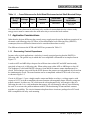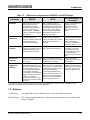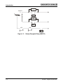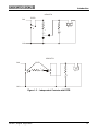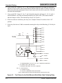
1
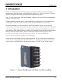
Union Switch & Signal Inc., an Ansaldo Signal company
1000 Technology Drive, Pittsburgh, PA 15219 ● 645 Russell Street, Batesburg, SC 29006
SM 9277
Shelf-Mounted, Solid State,
Biased, Code Following Relay
US&S Part No.
N40700403
♦ Installation
♦ Operation
Copyright © 2005
Union Switch & Signal Inc.
SM 9277, August 2005
Original
Proprietary Notice
This document and its contents are the property of Union Switch & Signal Inc. (hereinafter
US&S). This document has been furnished to you on the following conditions: no right or
license under any patents or any other proprietary right in respect of this document or its
content is given or waived in supplying this document. This document or its content are not
to be used or treated in any manner inconsistent with the rights of US&S, or to its
detriment, and are not to be copied, reproduced, disclosed to others, or disposed of except
with the prior written consent of US&S.
Important Notice
US&S constantly strives to improve our products and keep our customers apprised of changes
in technology. Following the recommendations contained in the attached service manual will
provide our customers with optimum operational reliability. The data contained herein purports
solely to describe the product, and does not create any warranties.
Within the scope of the attached manual, it is impossible to take into account every eventuality
that may arise with technical equipment in service. Please consult your local US&S Account
Executive in the event of any irregularities with our product.
We expressly disclaim liability resulting from any improper handling or use of our equipment,
even if these instructions contain no specific indication in this respect. We strongly recommend
that only approved US&S spare parts be used as replacements.
SM 9277, Original, August 2005
i
Revision History
Revision History
Rev.
Original
ii
Date
Nature of Revision
August 2005
Initial Release of Manual
SM 9277, Original, August 2005
Table of Contents
Table of Contents
1
Introduction............................................................................................................................................................ 1-1
1.1
Application Considerations ................................................................................................................... 1-2
1.1.1
Overcoming Contact Dependence ................................................................................................ 1-2
1.2
Glossary................................................................................................................................................ 1-3
2
2.1
2.2
2.3
Equipment Description ........................................................................................................................................ 2-1
Contacts and Current Ratings .............................................................................................................. 2-1
Isolation for Biased Solid-state Relays ................................................................................................. 2-1
Voltage Requirements .......................................................................................................................... 2-1
3
3.1
Installation.............................................................................................................................................................. 3-1
Relay Wiring.......................................................................................................................................... 3-1
4
4.1
4.2
Operation/Testing ................................................................................................................................................. 4-1
Operation .............................................................................................................................................. 4-1
Test Procedure ..................................................................................................................................... 4-1
5
Technical Support................................................................................................................................................. 5-1
List of Figures
Figure 1-1
Figure 1-2
Figure 1-3
Figure 3-1
Figure 4-1
Figure 4-2
- Typical Shelf-Mounted, Solid-State, Code Following Relay.......................................................... 1-1
- Steady Energized Relay (EMCFR)................................................................................................ 1-4
- Independent Contacts with ECFR ................................................................................................. 1-5
- Overall Dimensions of the Slid State, Code Following Relay ....................................................... 3-2
- Pin-Out Information for the Solid State, Shelf Mounted Relay ...................................................... 4-1
- Test Fixture for the Shelf-Mounted Solid-State Code Following Relay......................................... 4-2
List of Tables
Table 1-1 - Cross References for Solid-State/Electromechanical Shelf-Mounted Relays................................ 1-2
Table 1-2 - Differences in Application of EMCFR and ECFR Relays .............................................................. 1-3
Table 2-1 - Specifications for the Solid State Code Following Relay................................................................ 2-1
SM 9277, Original, August 2005
iii
Table of Contents
iv
SM 9277, Original, August 2005
Introduction
1 Introduction
This service manual provides installation and operation information for Union Switch & Signal’s
shelf-mounted, solid-state, biased, code following relay (Figure 1-1). This relay provides a solid-state
option for customers with existing electromechanical code following relays.
Table 1-1 cross references the US&S shelf-mounted, solid-state relay to the US&S electromechanical
CD style “cookie jar” relay.
The shelf-mounted, solid-state relay is a code following relay comprised of two circuit boards each
containing four solid-state switches. The two boards are housed in a W400 style enclosure.
On each of the boards, two of the switches are used as front contacts, and two are used as back
contacts. All of the switches are normally open devices, therefore, to emulate a back contact function it
is necessary to apply steady energy to one set of terminals on the upper terminal block to enable the
back contact switches. Applying energy to another set of terminals activates the front contact switches
and opens the back contact switches. In the event that back contacts are not required, it is not
necessary to enable them, because the front contact switches will operate independently.
The two circuit boards operate together to form a 4FB relay.
The circuit boards are designed for low-voltage applications. The low-voltage unit can support load
currents from 2.5 amperes up to 30 VDC, 22 volts Vrms AC. Breakdown voltage across a normalreverse contact set is limited by the surge protection ratings of 34 VDC for low-voltage contacts.
.
Figure 1-1 - Typical Shelf-Mounted, Solid-State, Code Following Relay
SM 9277, Original, August 2005
1-1
Introduction
Table 1-1 - Cross References for Solid-State/Electromechanical Shelf-Mounted Relays
CDP Style
Relay
Voltage
Ohms
Contacts
Solid-state
Replacement
Contact
Application
N223414
8-12
135
4FB LV
N40700403
4FB LV AC/DC
#1,2,3,4
The main difference between the solid-state relay and the electromechanical relay is that a steady
energy source must be connected to the solid-state relay to activate the back contacts.
1.1 Application Considerations
Other than the obvious difference that a steady energy supply must be used to duplicate operation of an
electronic code following relay (ECFR) to its electromechanical code following relay (EMCFR)
counterpart, there are differences that need to be considered that relate to safety.
The differences between the ECFR and EMCFR are presented in Table 1-2.
1.1.1 Overcoming Contact Dependence
In some safety critical applications a vital relay is steady energized proving that the EMCFR is
following code. The general way in which this is accomplished is illustrated in its simplest form in
Figure 1-2.
A snub on AFP and ABP delays drop-out for sufficient time so that AFP and ABP remain steady
energized as long as A is following code. When coding stops, either AFP or ABP drops as does AP.
This technique is valid with EMCFR’s because front and back contacts cannot simultaneously be
closed. This technique is not valid for the ECFR because the contacts are independently driven and can
be simultaneously closed. The same function can be accomplished with an ECFR in one of two ways
as shown in Figure 1-3.
Circuit A of Figure 1-3 uses a single transfer contact and diodes to achieve a voltage negative with
respect to N12; Circuit B accomplishes the same function with marginally better efficiency using two
transfer contacts. In either case, AP, which must be a biased neutral relay, will energize when A is
following the code. It is a vital mechanism that ensures AP will deenergize when A is not following
the code. It overcomes the problem inherent with ECFRs that shorting of front and back contacts
together is a possibility. The circuit elements to duplicate these circuits are packaged on a PC board
that is compatible with relay rack mounting.
1-2
SM 9277, Original, August 2005
Introduction
Table 1-2 - Differences in Application of EMCFR and ECFR Relays
Parameter
EMCFR
ECFR
Recommendation or
Comment
Calibration
Pick-Up and Drop-Away are
determined by the force
generated by a magnetic
structure and the restraining
forces of contact springs
and/or magnets. It is implied
that pick-up and drop-away are
thus assured.
Pick-up and Drop-Away are
primarily determined by photovoltaic devices for which there is
no implied guarantee that it will
never change. These devices
have proven highly repeatable
but calibration should not be
regarded as absolute.
Do NOT use an ECFR in an
application in which
calibration is critical to
safety. Note – in most
applications this is not a
factor.*
Contact
Dependence
Contacts are driven by a
common element and,
therefore, a welded contact will
prevent opposite state
contacts from conducting.
Contacts are independent. A
shorted contact, analogous to
one that is welded, will not inhibit
the others from functioning
normally.
Do NOT use an ECFR in an
application where dependent
contact operation is critical to
safety. (An example of
overcoming this problem is
presented in Section 1.1.1.)
Inductive Load
Switching
Preferred practice in switching
inductive load relays is to snub
the load to prevent arching,
EMI, and contact corrosion.
Transient protection is an integral
part of the solid-state switches.
External snubbing and arc
suppression devices are
unnecessary. Line-to-line
and line-to-ground arrestors
are recommended for
circuits that exit the house or
case.
Short Circuit
Protection
A short circuit can damage the
relay and possibly initiate a fire
in the wiring.
With the low voltage contacts, a
short circuit will cause no damage
to the wiring or the ECFR.
There should be less
concern about short circuits
with the ECFR.
Code Following
Integrity and
Reliability
Contacts open and close
substantially matching the ON
time of the code but erode with
time; this causes code ON
time distortion and eventually
contact failure. The rate of
contact failure is accelerated at
higher code rates and contact
loading. In cab signal
applications, the point on the
waveform of circuit interruption
is random.
Code ON time is more consistent.
There is no wear out mechanism
and, therefore, no degradation of
performance regardless of code
rate and contact loading.
For those applications
wherein the code follower is
repeating ON-OFF switching
from a code generator, the
ECFR is a superior device.
In cab signal applications, the
point of circuit interruption occurs
at the zero crossing resulting in
less harmonic noise generation
than would otherwise occur.
*Low resistance coil relays generally used as track relays are examples where calibration is critical to safety. Relays
discussed in the manual are not suitable for that or similar applications.
1.2 Glossary
Coded Energy
The signal that activates alternate closure of the front and back contacts.
Steady Energy
The voltage applied to the relay so that the contacts alternately switch when coded
energy is applied.
SM 9277, Original, August 2005
1-3
Introduction
snub
EMCFR
A
AFP
snub
ABP
AFP
ABP
AP
Figure 1-2 - Steady Energized Relay (EMCFR)
1-4
SM 9277, Original, August 2005
Introduction
CIRCUIT A
ECFR
B12
_
+
AP
A
_
+
+
_
N12
CIRCUIT B
B12
ECFR
_
+
A
_
+
AP
A
_
+
N12
Figure 1-3 - Independent Contacts with ECFR
SM 9277, Original, August 2005
1-5
Introduction
1-6
SM 9277, Original, August 2005
Equipment Description
2 Equipment Description
A summary of the specifications for the relay described in this manual are presented in Table 2-1.
2.1 Contacts and Current Ratings
The relay is for low voltage applications, and an AC/DC switch is provided. The load rating is 2.5
amperes per contact up to 30 volts DC and 22 Vrms. Low voltage contacts are protected up to 34 volts
and are short circuit protected.
Breakdown voltage across a normal-reverse contact set is limited by the surge protection ratings of 34
VDC for low-voltage contacts.
2.2 Isolation for Biased Solid-state Relays
The steady power source and code input are isolated. Contacts and inputs are isolated from each other
and the frame; the withstand voltage is 1500 Vrms. Breakdown voltage across a front-back contact set
is limited by the surge protection ratings of 34V.
2.3 Voltage Requirements
The operating voltage for the relay is 8 to 16 volts DC. Ripple must be limited so that the
instantaneous voltage does not drop below 8 volts.
Table 2-1 - Specifications for the Solid State Code Following Relay
Parameter
Operating Voltage
Contact Load Rating
Value
8 to 16 VDC (can not drop below 8 VDC)
Hold Current
0.06 to 2.5 Amps
Voltage
12 to 230 Vrms
Contact Protection
Up to 230 volts (Contacts are NOT shortcircuit protected. External fusing is required
for short circuit protection.)
Operating Temperature Range
-40°C to +70°C
Overall Dimensions
SM 9277, Original, August 2005
Height
9.25”
Width
4.56”
Length
6.0”
2-1
Equipment Description
2-2
SM 9277, Original, August 2005
Installation
3 Installation
The solid-state, shelf-mounted relays may be installed either on a horizontal shelf or mounted to a
panel and installed in an equipment rack. The shelf-mounted relays do no utilize index plates. The
dimensions for installing the relay are presented in Figure 3-1.
These relays operate as a 4FB relay; the terminal pinouts are shown in Figure 4-1.
3.1 Relay Wiring
For the shelf-mounted, solid-state relay, the coded and steady energy, as well as the contact connection
points, are connected to AAR terminals on the top of the unit. Positive coded energy is wired to
terminal +Coded, negative coded energy is wired to terminal -Coded. Positive steady energy is wired
to terminal +12 Steady; negative steady energy is wired to terminal -12 Steady. (See Figure 4-1.)
SM 9277, Original, August 2005
3-1
Installation
6”
4.56”
3.5”
.53”
.63”
2.25”
.53”
.63”
1.19”
.81”
.31” .14” R.
.25”
7.63”
7.5”
.56”
8.5”
7.13”
8.19”
9.25”
.25” R.
2.25”
.28” DIA HOLE
6”
Figure 3-1 - Overall Dimensions of the Slid State, Code Following Relay
3-2
SM 9277, Original, August 2005
Operation/Testing
4 Operation/Testing
4.1 Operation
The shelf-mounted relay operates as a 4FB relay and must be wired as described in Section 3.1.
The applied coded energy closes the front contact switches and opens the back contact switches.
4.2 Test Procedure
No periodic testing or adjustment is necessary. There are no calibration or adjustments required on the
solid-state relay.
Testing a solid-state relay differs slightly from testing an electromechanical relay. A minimum
operating voltage replaces the pick up calibration. Testing consists of energizing the relay with 8 volts
DC and observing that the contacts close. An AC source is used to indicate contact closure.
To test the shelf-mounted relay, connect it to a test fixture wired as shown in Figure 4-2.
1. Turn on the AC power by closing switch SW1. No lamp should be illuminated. Any lit lamp
indicates a shorted switch.
Figure 4-1 - Pin-Out Information for the Solid State, Shelf Mounted Relay
(Viewed from the Top of the Relay)
SM 9277, Original, August 2005
4-1
Operation/Testing
2. Close switch SW2. Lamps L5, L6, L7, and L8 should be illuminated. Any lamp not illuminated
indicates an open switch. (This assumes that the indicator lamps are intact. If a lamp is not lit, the
bulb can be checked by shorting the front or back contact wire to the heel contact wire. With this
short the bulb should light.)
3. Close switch SW3. Lamps L5, L6, L7, and L8 should extinguish, and lamps L1, L2, L3, and L4
should illuminate. Any lamp not illuminated indicates an open switch. (This assumes that the
indicator lamps are intact. Check the bulb per Step 2 if it is not lit.)
4. If the test results are satisfactory, the relay test is complete. Return all switches to their "off"
position.
5. If the relay fails the test, US&S recommends returning the relay to their Batesburg, SC facility for
repair.
L1
L2
L3
SW1
F1
L4
T1
+
TO 120 V
AC LINE
_
L5
L6
L7
L8
TO 1F
TO 2F
TO 3F
TO 4F
TO 1B
TO 2B
TO 3B
TO 4B
TO 1H
TO 2H
VOLTAGE
REGULATOR
TO 3H
LM7808
D1
TO 4H
+
C1
SW2
SW3
TO +12 STEADY
TO + CODED
TO -12 STEADY
TO - CODED
T1: TRANSFORMER, 120 V AC TO 12 V AC, 2 AMPERES OR BETTER
L1 - L8: LAMPS, #1891, 1892, OR 1893
D1: BRIDGE RECTIFIER, 100-VOLT, 5-AMPERE
SW-1, 2, 3: SPST SWITCH
C1: 100 MFD, 50-VOLT
F1: 120 VOLT, 3-AMPERE FUSE, AND HOLDER
MISC: LAMP SOCKETS, WIRE MOUNTING BASE, AND RECEPTACLES
Figure 4-2 - Test Fixture for the Shelf-Mounted Solid-State Code Following Relay
4-2
SM 9277, Original, August 2005
Technical Support
5 Technical Support
The Rapid Action Information Link Team (RAIL Team) is a group of experienced product and
application engineers ready to assist you to resolve any technical issues concerning this product.
Contact the RAIL Team at 1-800-652-7276 or by e-mail at [email protected].
SM 9277, Original, August 2005
5-1
Technical Support
5-2
SM 9277, Original, August 2005