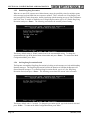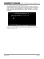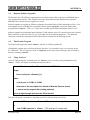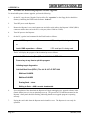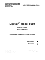
1
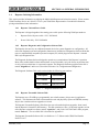
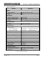
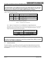
SERVICE MANUAL 7068
645 Russell Street
Batesburg, SC 29006
®
Digitair Model 6680
END-OF-TRAIN
REPEATER UNIT
Communication Interface Unit (CIU)-type Enclosure
December, 1997
© 1997, Union Switch & Signal Inc.
Printed in the U.S.A.
Installation
Operation
An ANSALDO Signal Company
TABLE OF CONTENTS
Section Subject
1.0
General Information .........................................................................................................................1-1
1.1
2.0
Page
General Overview and Functional Description..................................................................1-1
1.1.1
Repeater Power-Up..............................................................................................1-2
1.1.2
Repeater Functions and Capabilities ....................................................................1-2
1.2
Repeater Message Protocol Compatibility ........................................................................1-2
1.3
R.A.I.L. Team and Technical Support ..............................................................................1-2
1.4
Repeater Ordering Information.........................................................................................1-3
1.4.1
Repeater Unit and Power Cable ...........................................................................1-3
1.4.2
Repeater Diagnostic and Configuration Software Disk ........................................1-3
1.4.3
Repeater Executable Software Disk .....................................................................1-3
1.5
Repeater Major Hardware Assemblies..............................................................................1-4
1.6
Repeater Specifications ....................................................................................................1-5
Installation of the Repeater...............................................................................................................2-1
2.1
Items Required for Installation and Configuration ............................................................2-1
2.2
Model 6680 Repeater Unit Packaging Issues....................................................................2-1
2.3
Repeater Unit Installation.................................................................................................2-1
2.4
Power Supply Installation and Connections ......................................................................2-1
2.4.1
3.0
Repeater Transmit Power Level and Related Power Supply Requirements...........2-2
2.5
Antenna Installation .........................................................................................................2-2
2.6
Repeater Power-Up and Operational Verification............................................................. 2.3
2.6.1
Repeater Configuration........................................................................................2-3
2.6.2
Basic Troubleshooting and Fuse Replacement .....................................................2-3
Configuration and Diagnostics .........................................................................................................3-1
3.1
Digitair® Diagnostic Software ..........................................................................................3-1
3.2
Running the Diagnostic Software .....................................................................................3-1
SM7068 (12/97)
Page i
TABLE OF CONTENTS
Section Subject
Page
3.3
Main Menu.......................................................................................................................3-3
3.4
Diagnostic Items...............................................................................................................3-4
3.5
Configuration Items Menu................................................................................................3-4
3.5.1
Enable High Power Transmit...............................................................................3-5
3.5.2
Repeat Only Normal Message Types ...................................................................3-6
3.5.3
Use Radio Squelch ..............................................................................................3-6
3.5.4
Select ID That Will Not Be Repeated...................................................................3-7
3.5.5
Enable Ping-Pong Prevention ..............................................................................3-8
3.5.6
Set Ping-Pong Prevention Period .........................................................................3-8
3.5.7
Enable Prevention of Repeating a Repeater Message...........................................3-9
Appendix A
A.1
Repeater Software Upgrades .......................................................................................................... A-1
A.2
Flash Loader Program .................................................................................................................... A-1
A.3
Using “Load.exe” ........................................................................................................................... A-1
A.4
Procedure for Downloading Repeater Software Upgrades ............................................................... A-2
Tables and Figures
Figure 1.1
Repeater Unit ...................................................................................................................1-1
Table 1.1
Diagnostic Software Disk.................................................................................................1-3
Figure 1.2
Repeater Hardware Assemblies ........................................................................................1-4
Table 1.2
Repeater Specifications ....................................................................................................1-5
Table 2.0
Repeater Power Connections ............................................................................................ 2-2
Table 2.1
Repeater Transmit Power Levels ......................................................................................2-2
Table 2.2
Fuse Functions and Ratings .............................................................................................. 2-3
Page ii
SM7068 (12/97)
SECTION 1.0: GENERAL INFORMATION
This manual provides information on the installation and operation of the DIGITAIR Model 6680 End-of-Train
Repeater Unit. Refer to Service Manual SM 7069 for detailed Shop Maintenance information.
1.1
General Overview And Functional Description
The primary purpose of the DIGITAIR Repeater Unit is to relay End-of-Train (EOT) telemetry messages from
the rear of the train to the front of the train and vice versa (i.e., from the EOT End Unit to the EOT Cab Unit,
and vice versa). The Repeater is typically used in areas where radio signals are weak due to surrounding terrain
conditions or where there exists RF “dead” spots such as in many train yards. As such, the Repeater should be
installed in a strategic location where it will provide maximum radio coverage in the area in which it will be
used.
The Repeater is housed in a single “Communication Interface Unit (CIU)”-type enclosure as depicted in Figure
1.1. The unit is powered from an external DC power source via a power cable that plugs into its front panel
mounted Host Interface connector. Connection to a UHF ¼ wave antenna is accomplished via the Repeater’s
front panel mounted “N”-type RF antenna connector.
Figure 1.1 - Repeater Unit
SM7068 (12/97)
Page 1-1
SECTION 1.0: GENERAL INFORMATION
1.1.1
Repeater Power-Up
The Repeater has no power switch; it is meant to be operational at all times. The unit is powered on
when a DC power source is applied to its Host Interface connector. The unit then indicates that it is
operational by continuously flashing its green STATUS indicator.
1.1.2
Repeater Functions and Capabilities
The Repeater hardware is designed using the latest in microcontroller technology, making it an
“intelligent” device capable of performing several powerful functions in addition to its main function of
relaying EOT messages. These are configurable via a serial connection from the Repeater to a standard
PC and include the following:
Built-in diagnostics;
Selection of normal 2-Watts transmission or high-power 4-Watts transmission (as required);
Ability to repeat only normal EOT messages or, by configuration, to repeat special messages
types used for other applications;
Can be programmed to NOT repeat (i.e., block out) up to 4 EOT ID Codes. This helps reduce
radio traffic in yards where EOT beacons or test EOTs have been installed;
Functions can be enabled to prevent multiple repeats of the same EOT message when two or
more Repeaters are operating within telemetry range of each other. This is commonly referred
to as “ping-pong” prevention.
These and other functions are described in Section 3.0 - Configuration and Diagnostics.
1.2
Repeater Message Protocol Compatibility
The Model 6680 Repeater is compatible with all EOT equipment employing existing protocols such as the
American Association of Railroads (AAR) End-of-Train message protocol. It meets or exceeds the guidelines of
the AAR, as well as the Federal Railroad Administration (FRA), the Federal Communications Commission
(FCC) and Industry Canada (IC) regulations.
1.3
R.A.I.L. Team and Technical Support
The Rapid Action Information Link (R.A.I.L.) Team is comprised of experienced
product and application engineers ready to assist and resolve any technical issues
concerning DIGITAIR End-of-Train equipment or any US&S product.
Any questions regarding the contents of this Service Manual should be directed to the
R.A.I.L. Team via telephone at 1-800-652-7276 or via Internet e-mail at:
[email protected].
Page 1-2
SM7068 (12/97)
SECTION 1.0: GENERAL INFORMATION
1.4
Repeater Ordering Information
This section provides information on ordering the Model 6680 Repeater and related accessories. Please contact
US&S Customer Service at 1-800-652-7276 or your US&S Sales Representative for technical information,
pricing and additional sales information.
1.4.1
Repeater Unit and Power Cable
The Repeater is shipped together with a mating power cable per the following US&S part numbers:
1.
Repeater Unit with power cable - P/N: N24300101
2.
Power Cable Only - P/N: N24306001
1.4.2
Repeater Diagnostic and Configuration Software Disk
The Repeater does not rely on a dedicated external device for system diagnostics or configuration. All
of the unit diagnostic tests and configuration functions are included on a Diagnostics Software Disk that
runs on a standard DOS-compatible personal computer (PC) which plugs into the Repeater’s internal
DB-9 style Diagnostic Port.
The Diagnostic Software has been designed to permit easy customization of the Repeater’s operation.
Most of the variable default values and functions are user-selectable, set by the factory at purchase time,
or set by railway technicians via a personal computer. The Diagnostic Software program on the disk is
named “diagunit.exe” and its use is described in Section 3.0, Configuration and Diagnostics.
The Diagnostic Software Disk can be ordered under the following part numbers:
Description
Part Number
3.5” Diskette
N451232-1264
5.25” Diskette
N451232-1265
Table 1.1 - Diagnostic Software Disk
1.4.3
Repeater Executable Software Disk
The Repeater uses a FLASH-type programmable, non-volatile memory chip to store its application
software. This eliminates the need to disassemble the unit and physically replace an EPROM (memory
chip) in the event that software upgrades are issued.
The Repeater Executable Software disk allows the user to download software upgrades, when issued,
into the Repeater’s internal FLASH memory. This disk contains two files, (1) the latest upgrade version
of the Repeater executable software, named “repeat.hex”, and (2) the Cab Unit Flash Loader program,
named “load.exe”. The use of this disk is described in Appendix A.
The Repeater Executable Software disk is available on a 3.5” diskette under US&S Part Number
N451232-1637.
SM7068 (12/97)
Page 1-3
SECTION 1.0: GENERAL INFORMATION
1.5
Repeater Major Hardware Assemblies
Figure 1.2 shows the Repeater with its cover removed, exposing its major hardware assemblies and the location
of the Diagnostic Connector:
Figure 1.2 - Repeater Hardware Assemblies
Page 1-4
SM7068 (12/97)
SECTION 1.0: GENERAL INFORMATION
1.6
Repeater Specifications
Parameter
Specification
Physical:
Overall Dimensions
H = 9.25”, W = 2.50”, D = 11.60”
Weight
4 lbs.
Environmental:
Operating Temperature Range
-30C to +50C
Storage Temperature Range
-55°C to 100°C
Humidity
95% non-condensing at 40C, 96-hour exposure
Power Requirements:
DC Power
12 VDC to 15 VDC @ 2A
Radio Transceiver:
Radio Frequencies:
Front-to-Rear Messages
452.9375 Mhz
(Other frequencies available
Rear-to-Front Messages
457.9375 Mhz
at customer request)
Transmit Power
2-Watts (standard) or 4-Watts (requires 15 VDC)
Transmit Frequency Stability
5 PPM
Emission
16K0F2D
Deviation (at 1200 Hz)
3.3 KHz
Receive Sensitivity (-12 dB SINAD)
0.45 uV (max)
Receive Frequency Stability
10 PPM (max)
Selectivity
60 dB (min)
Intermodulation Immunity
60 dB (min)
Spurious Rejection
55 dB (min)
Image Rejection
50 dB (min)
PC Diagnostic Interface:
Asynchronous Serial Data Rate
9600 Baud, 1 Stop Bit, 8 Data Bits
Voltage Level
EIA RS-232C
Table 1.2 - Repeater Specifications
SM7068 (12/97)
Page 1-5
SECTION 2.0: INSTALLATION OF THE REPEATER
This section describes the installation of the Repeater and how to connect power and a UHF antenna to the unit.
Configuration and verification of proper operation after power-up are also discussed.
2.1
Items Required for Installation and Configuration
Items required to install the Repeater include the following:
Repeater Unit (CIU-type enclosure)
Power Cable (either supplied with the Repeater or available separately)
Diagnostic Software Disk
Items to be supplied by user include:
2.2
Power Supply (12 VDC nominal for 2-Watt operation, 15-VDC nominal for 4-Watt operation)
¼ Wave UHF Antenna terminated with an N-type RF connector
Grounding and Lightning protection (as required)
Mounting hardware (as appropriate for the particular installation location)
PC serial communications cable, DB-9 type, straight-through, male-to-female connectors.
Model 6680 Repeater Unit Packaging Issues
The Model 6680 Repeater Enclosure was designed to operate as an Head-of-Train Device (HOTD)
Communication Interface Unit (CIU) and, as such, is packaged in an LSI-compliant HOTD CIU enclosure. For
background purposes, the HOTD CIU operates as an EOT Front End Unit and is meant to be rack-mounted in a
locomotive that is equipped with an Integrated Cab. As such, the package does not incorporate mounting tabs.
2.3
Repeater Unit Installation
The Repeater must be installed indoors or in a wayside hut or bungalow, where it will be protected from wet
weather conditions. Securely mount the Repeater in an available location, such as an empty equipment rack
shelf, using appropriate mounting hardware dependent on the location chosen. It is recommended that the
Repeater be installed so that its cover can be removed for easy access to the internal Diagnostic Connector and
for adjustments.
2.4
Power Supply Installation and Connections
The power supply, which is furnished by the user, should be installed using the same care and techniques as
those described for the Repeater. The power cable, which is provided, is approximately 6 feet in length.
The power cable is supplied with a connector pre-mounted on one end, the other end is unterminated. Plug the
power cable connector into the Repeater’s host interface connector. Only two pins on the host interface
connector are used. Pin assignments and lead color codes are as shown in Table 2.0.
SM7068 (12/97)
Page 2-1
SECTION 2.0: INSTALLATION OF THE REPEATER
CAUTION
Non-standard cables, or those supplied by the railroad, may employ different color codes than
those used by US&S. Refer to the connector pin assignments in this manual or consult US&S
Customer Service at 1-800-652-7276 for further technical assistance, if required.
Cut the unterminated end of the cable to the desired length. Strip and install whatever spade lug, tab, or other
contact is required for the power supply.
Pin
Conductor
Power Cable Connector (MS3106A-20-29S)
D
Red
Power Supply Positive (+ 12 VDC or +15 VDC)
J
Black
Power Supply Ground
Note: Other Pins Not Used for Repeater Application
Table 2.0 - Repeater Power Connections
2.4.1
Repeater Transmit Power Level and Related Power Supply Requirements
The Repeater can be configured to operate at a standard 2-Watt transmit power level or at an increased
high power transmit level of 4-Watts (refer to Section 3.0 for configuration information). The power
supply requirements for the two levels are as follows:
Transmit Power Level
2-Watts
4-Watts
Power Supply Requirements
+12 VDC @ 2 Amps
+15 VDC @ 2 Amps
Table 2.1 - Repeater Transmit Power Levels
NOTE
Special FCC Licensing may be required if 2 watts Effective Radiated Power (ERP) is exceeded.
Consult FCC Part 90 Rules and Regulations.
2.5
Antenna Installation
The antenna should be a ¼-wave UHF-type unit with the required cable length terminated in an N-style RF
connector. Connection to the Repeater simply involves plugging the “N” connector into the Repeater’s front
panel mounted antenna connector. The user must provide adequate grounding and proper lightning protection
for the Repeater.
Page 2-2
SM7068 (12/97)
SECTION 2.0: INSTALLATION OF THE REPEATER
2.6
Repeater Power-Up and Operational Verification
With the Repeater fully installed, apply power to the unit. Observe that the green STATUS indicator on the
Repeater’s front panel begins to flash and continues to flash indefinitely. This indicates that the Repeater
software is running and that the processor board is operational.
The Repeater is now ready for use.
As an additional measure, if available, use an RF Communication Monitor to verify that the Repeater is
transmitting front-to-rear and rear-to-front EOT messages at the frequencies stated in Section 1.6 - Repeater
Specifications.
2.6.1
Repeater Configuration
If required, the user can configure the Repeater at this time. To configure the Repeater, remove its cover
and follow the instructions provided in Section 3.0 - Configuration and Diagnostics.
2.6.2
Basic Troubleshooting and Fuse Replacement
If the Repeater does not operate as described above, check the following:
1.
Unplug the power cable connector from the Repeater. Confirm proper pin assignments
according to Section 2.4 and verify that correct DC voltage appears on the pins as listed in Table
2.0.
2.
Remove the Repeater’s cover and check the fuses. Replace the fuse(s) as required per
Table 2.2.
Fuse Designation
Function of Fuse
Fuse Rating
F1
Radio Module
2-Amp, 250 Volt (2-Watt Operation)
3-Amp, 250 Volt (4-Watt Operation)
F2
Electronics
2-Amp, 250 Volt
Table 2.2 - Fuse Functions and Ratings
If the unit still does not operate properly, it will require more detailed troubleshooting per Service
Manual SM 7069 - Shop Maintenance, or must be sent out for repair.
SM7068 (12/97)
Page 2-3
SECTION 3.0: CONFIGURATION AND DIAGNOSTICS
The Repeater incorporates a diagnostic port, which is used to access the built-in configuration and diagnostic
functions. This port is comprised of a DB-9 type RS-232/C serial connector and is located on the processor
board (J6) inside the Repeater’s enclosure. The port connects to a DOS-compatible PC via a standard straightthrough, 9-pin male-to-female serial computer cable. The female connector type will be determined by the port
on your PC. Straight-through male-to-female cables are commercially available.
3.1
Digitair® Diagnostic Software
Digitair® Diagnostic Software running on a PC provides a full set of menu-driven configuration and diagnostic
functions. The diagnostic software is a single program named “diagunit.exe” supplied on a floppy disk. The
software can be ordered under US&S part number N451232-1264 (3.5” disk) or N451232-1265 (5.25” disk).
NOTE
This manual provides some examples of the diagnostic functions and provides detailed
information on Repeater configuration. Refer to Service Manual SM 7069 (Shop Maintenance)
for detailed diagnostic information and procedures.
3.2
Running the Diagnostic Software
To run the diagnostic software, perform the following:
1.
To gain access to the diagnostic port, remove the Repeater’s cover.
CAUTION
The Repeater contains static-sensitive components. Always observe proper ESD handling
procedures; otherwise, equipment damage may result.
2.
With the diagnostic PC powered-on, execute the diagnostic software from the floppy disk (or from the
PC’s hard disk if it has been copied there) by typing “diagunit” followed by <Enter>.
3.
The following Diagnostic Start-Up Screen will appear as shown. The program name and version appear
at the top of the screen. The box at the bottom of the screen displays any prompts for user input. The
last line shows applicable PC function keys.
SM7068 (12/97)
Page 3-1
SECTION 3.0: CONFIGURATION AND DIAGNOSTICS
4.
Connect the serial computer cable between the diagnostic PC and the Repeater’s Diagnostic Port
connector.
NOTE
The Repeater’s Diagnostic Port is permanently set for 9600 baud, 8-data bits, 1-stop bit and no
parity. The Diagnostic Software sets the PC’s serial port to these same values; therefore, no
configuration should be required.
5.
The Diagnostic Software defaults to PC serial port COM1. If use of COM2 is required, press <F2> to
use COM2. Press <F1> to return to COM1.
6.
Note that the Repeater has no switches or buttons. To proceed, power-up the Repeater.
7.
The diagnostic PC will then display the Initial Diagnostic screen as follows:
8.
To quit the program at any time, press <F4>. The program will prompt with “Really quit? [Y, N]:”. If
“Y” is selected, the program will terminate. If “N” is selected, the program will continue.
Page 3-2
SM7068 (12/97)
SECTION 3.0: CONFIGURATION AND DIAGNOSTICS
9.
To access the primary diagnostic/configuration screen, type “1” (Start Main Program Diagnostics) and
press <Enter>. The following screen will appear.
Press <Esc> to proceed to the Main Menu. Also observe that the Repeater’s green “STATUS” light
begins to flash, indicating that the main application program is now running.
3.3
Main Menu
To select one of the submenus associated with Diagnostic Items or Configuration Items, type the desired
menu item and press <Enter>.
SM7068 (12/97)
Page 3-3
SECTION 3.0: CONFIGURATION AND DIAGNOSTICS
3.4
Diagnostic Items
This Diagnostic Items Menu displays selections that may show information about, or perform a diagnostic test
on, specific elements of the Repeater.
Select a diagnostic test from this menu by typing in a menu item number followed by <Enter>. To return to the
Main Menu, press <Esc>.
NOTE
The use of the Diagnostic Items is beyond the scope of this manual. Each Diagnostic Item is
described in detail in the Repeater Shop Maintenance Manual, SM 7069.
3.5
Configuration Items Menu
The Configuration Items Menu displays selections that allow Repeater functions to be enabled or disabled and
also allows customization of certain functions. This section describes the purpose and use of each menu item as
shown below in the Main Configuration Menu:
To select an item from this menu, type in a menu item number and press <Enter>. To return to the Main Menu,
press <Esc>.
Page 3-4
SM7068 (12/97)
SECTION 3.0: CONFIGURATION AND DIAGNOSTICS
3.5.1
Enable High Power Transmit
The Repeater normally transmits repeated EOT messages at 2-Watts RF power; however, it has the
capability to transmit at a 4-Watt power level if required by the railroad. To select the transmit power
level, type in “1” (Enable High Power Transmit) and press <Enter>. The following screen shows the
currently selected setting:
The factory default setting is typically “0” for the 2-Watt power level.
To enable high power transmit at 4-Watts, type in the menu item number and press <Enter>. To return
to the Main Configuration Menu, press <Esc>.
NOTE (4-Watt Operation)
Operation at 4-Watts requires that the Repeater be powered from a 15 VDC source. It may
also require that the user apply for special licensing with the FCC to operate in excess of
2-watts Effective Radiated Power.
SM7068 (12/97)
Page 3-5
SECTION 3.0: CONFIGURATION AND DIAGNOSTICS
3.5.2
Repeat Only Normal Message Types
The Repeater is typically used to relay standard AAR-type EOT messages. The Repeater also can be
used to repeat non-AAR defined messages, such as those transmitted by US&S’ Wayside
Communication Unit (WCU). To select the type of message to be repeated, type in “2” (Repeat Only
Normal Message Type) and press <Enter>. The following screen shows the currently selected setting:
To change the operational mode, type in the menu item number and press <Enter>. To return to the
Main Configuration Menu, press <Esc>.
3.5.3
Use Radio Squelch
The Repeater can use its transceiver squelch level in conjunction with the Carrier Detect signal to detect
the presence of an EOT message. It also can operate without squelch by “hunting” for the message sync
bits that precede every message. Operating the Repeater without squelch improves reception of weak
radio signals when operating the unit in extreme cold temperatures.
To enable or disable the use of radio squelch, type in “3” (Use Radio Squelch) and press <Enter>. The
following screen shows the currently selected setting:
To change the operational mode, type in the desired menu item number and press <Enter>. To return
to the Main Configuration Menu, press <Esc>.
Page 3-6
SM7068 (12/97)
SECTION 3.0: CONFIGURATION AND DIAGNOSTICS
3.5.4
Select ID That Will Not Be Repeated
The Repeater can be programmed with up to four EOT ID Codes that will not be repeated (i.e., blocked
out). This helps reduce yard radio traffic by allowing the user to block out Test EOTs, beacons or
similar equipment often used in yards. It is desirable not to re-broadcast messages transmitted by these
devices via the Repeater.
To select the ID Code of the message not to be repeated, type in “4” (Select ID Which Will Not Be
Repeated) and press <Enter>. The following screen shows the options to either select and/or clear
each of the four ID Codes.
To enter an ID Code or clear out a code that has already been stored, type in the corresponding menu
item number and press <Enter>. Clearing a code sets it to “00000” (note this is also the default factory
setting for all four ID Codes).
Note that the valid range of ID Codes is “00000” through “99999”.
The screen below shows an example of ID Code “05000” entered for the first ID Code NOT to be
repeated.
Press <Esc> to return to the Select ID screen. Press <Esc> a second time to return to the Main
Configuration Menu.
SM7068 (12/97)
Page 3-7
SECTION 3.0: CONFIGURATION AND DIAGNOSTICS
3.5.5
Enable Ping-Pong Prevention
When two or more EOT repeaters are within telemetry range, the possibility exists for multiple repeats
of the message back and forth from one repeater to another. This is referred to as “Ping-Ponging” and
can jam up the EOT radio frequencies, thereby interfering with the Arming process or with Communications Link Tests. To enable or disable the use of Ping-Pong Prevention, type in “5” (Enable Ping-Pong
Prevention) and press <Enter>. The following screen shows the currently selected setting:
The factory default setting is “True” (enabled) and is the recommended setting. To change the
operational mode, type in the desired menu item number and press <Enter>. To return to the Main
Configuration Menu, press <Esc>.
3.5.6
Set Ping-Pong Prevention Period
The Repeater accomplishes Ping-Pong Prevention by looking at each message received and discarding
identical messages. The Ping-Pong Prevention Period is the duration of time that the Repeater will
discard identical messages. To set the Ping-Pong Prevention Period, type in “6” (Set Ping-Pong
Prevention Period) and press <Enter>. The following screen shows the current value in seconds:
The factory default value is 3 seconds. To change the prevention period, type in the desired value and
press <Enter>. To return to the Main Configuration Menu, press <Esc>.
Page 3-8
SM7068 (12/97)
SECTION 3.0: CONFIGURATION AND DIAGNOSTICS
3.5.7
Enable Prevention of Repeating a Repeater Message
US&S Repeaters append a special “repeater signature” to each message relayed. As such, US&S
Repeaters can identify a message repeated by another US&S Repeater. This function, when enabled,
prevents “Ping-Ponging” between US&S Repeaters. To enable this function, type in “7” (Enable
Prevention of Repeating a Repeater Message) and press <Enter>. The following screen shows the
current setting:
The factory default setting is “True” (enabled) and is the recommended setting. To change the
operational mode, type in the desired menu item number and press <Enter>. To return to the Main
Configuration Menu, press <Esc>.
SM7068 (12/97)
Page 3-9
APPENDIX A
A.1
Repeater Software Upgrades
The Repeater uses a FLASH-type programmable non-volatile memory chip as opposed to an EPROM chip to
store its application software. This eliminates the need to disassemble the unit and physically replace the
EPROM in the event that software upgrades are issued.
Software upgrades are supplied by US&S on a Repeater Executable Software Disk containing two files: (1) the
latest upgrade version of the Repeater executable software named “repeat.hex” and (2) the Flash Loader
program named “load.exe”. This is a 3.5” disk and is available under US&S Part Number N451232-1637.
Software upgrades are downloaded into the Repeater’s Flash memory from a PC connected to the unit’s internal
DIAG connector via the same 9-pin “D” type serial cable used for performing diagnostics. The download
function is performed by running the Flash Loader Software as detailed in the following sections.
A.2
Flash Loader Program
The Flash Loader program is named “load.exe” and runs on a DOS-compatible PC.
Although this program may be run from the floppy disk drive, it is preferable to copy it to a directory on the
PC’s hard drive. The new upgrade version of “repeat.hex” must reside on the same floppy disk or hard drive
directory containing “load.exe”.
A.3
Using “load.exe”
At the PC DOS prompt, the command syntax for “load.exe” can be viewed by typing in load followed by
<Enter>. The PC will display the command structure as follows:
Cab Unit Flash Loader (Rev 1) Thu Jul 18 16:11:41 EDT 1996
Usage:
load -<serial port> <filename> [-r]
where
-<serial port> is -COM1 or -COM2
<filename> is the executable to be loaded in Motorola Exormax format.
-r means run the program after loading (optional)
Use a straight-through cable from the PC to the Unit.
Therefore, the typical command line, depending on the PC serial port being used, will be:
load -COM1 repeat.hex -r <Enter>
if PC serial port 1 is being used;
load -COM2 repeat.hex -r <Enter>
if PC serial port 2 is being used.
or
SM7068 (12/97)
Page A-1
APPENDIX A
A.4
Procedure for Downloading Repeater Software Upgrades
To download Repeater software upgrades, perform the following:
1.
On the PC, copy the new Upgrade Version of the file “repeat.hex” to the floppy disk or hard drive
directory containing the Flash Loader Software “load.exe”.
2.
Turn OFF power to the Repeater.
3.
Remove the Repeater’s cover and connect one end of the serial cable to the Repeater’s DIAG (DB-9)
connector and the other end to the PC’s serial port (either COM1 or COM2).
4.
Turn ON power to the Repeater.
5.
On the PC, type the load command for the Flash Loader as follows:
load -COM1 repeat.hex -r <Enter>
if PC serial port 1 is being used.
or
load -COM2 repeat.hex -r <Enter>
if PC serial port 2 is being used.
The PC will display the progress of the download process as follows:
Cab Unit Flash Loader (Rev 1) Thu Jul 18 16:11:41 EDT 1996
Press a key at any time to quit this program.
Initiating target diagnostics:
Cab Unit Boot Prom (REV 1) Thu Jul 18 9:37:47 EDT 1996
ROM test PASSED
RAM test PASSED
Erasing flash ... done.
Writing to flash ... #### records downloaded.
6.
Upon completion of the download, the Repeater will begin running the new upgrade software in the
normal fashion just as it does on standard power-up. The green STATUS indicator mounted on the
Repeater’s front panel should be flashing, indicating that the new upgrade program is operating
correctly.
7.
Unplug the serial cable from the Repeater and reinstall its cover. The Repeater is now ready for
operation.
Page A-2
SM7068 (12/97)