1
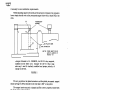
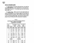
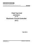
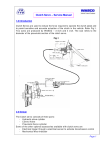
IUNION SWITCH & SIGNAL
645 Russell Street
Batesburg, SC 29006
I~
Service Manual 2666-J
DN-22B
Standard Biased Relay
Service Manual
July, 1965
B0.59-~00-1009.3
· © 1976, Union Switch & Signal Inc.
Printed in U.S.A.
I
An ANSALDOI Affiliated Company
WRBCC
~
SERVICE SPECIFICATION su . 2666-J
~
DN-22B STANDARD BIASED RELAY
********************
(For other information see Service Spec. SU-2666)
The relays of this service specification are similar to standard DN-22 relays covered by Service Specification SU-2666, but a permanent magnet is used
to hold down the neutral armature when the relay is deenergized or energized
with reverse polarity. Due to the space taken by the permanent magnet, front
contacts are used only in the outer contact spaces. Service Specification SU2666 (standard DN-22 relay) instructions apply to DN-22B standard biased relays
except as otherwise specified herein.
ARMATURE AIR GAP
The armature air gap should be adjusted as closely as possible to 0. 018 11
parallel (0. 019" if the rust protective coating has been removed from the pole
faces). The physical air gap after painting should not be less than 0. 017". If it
is necessary to repaint the pole faces, we recommend that Union Pole Face
Treatment per Instruction Pamphlet U-5038 be used. This pamphlet also covers
an aluminum paint material for touching up armatures, backstraps and similar
parts.
PERMANENT MAGNET
A. Permanent magnets should be removed from relays being repaired then
fully charged in the charger as shown in Fig. 1 and immediately assembled to the
relay. The magnets must not be stored or handled after charging except to apply
to the relay. The magnet should be placed on the charger core with the "N" face
up as shown in the diagram. The 2-hole face on the "N" side should attract the
end of a compass needle which points toward geographic South.
B. Assemble the permanent magnet to the relay and adjust, using a spacer
0. 075" thick at the main upper stop-pin so that the magnet just clears the armature lower stop-pin. For this adjustment do not energize the relay to hold the
armature against the spacer but hold it manually so as to bring the armature as
close to the pole pieces as the spacer and the pivot clearance will permit. The
spacer used for adjustment may be changed between the limits of 0. 065" to O. 090"
~
PRINTED
IN
U.S.A.
BO. 59-300-1009. 3
UNION SWITCH & SIGNAL DIVISION
Westinghouse Air Brake Company
PITISBURGH, PA. 15218
~
July 1965
if necessary to meet calibration requirements.
With the adjusting spacers removed and the armature released, the armature
lower stop-pin should rest on the permanent magnet shoe with at least 50% of its
area.
"x"
11)(. II
I
I
I
I
I
I
"x"
~K
SOFT IRON FILLER CORE
7"
'i
MIN. DIAMETER
NOTE+ THERE MUST BE NO
GAPS IN JOINTS AT
11
1
POINTS X~
Charger illustrated is Pc. UN248674, for DP-25 relay magnets,
modified with the filler core. Charger for DP-14 relay magnets may be used if similarly modified and proper polarity of
charge is observed.
FIGURE 1
The air gap between the plated armature and the plated permanent magnet
should average 0. 004" but should be not less than O. 003" at any point.
The magnet must be securely clamped and the screws properly locked with
the sheet metal washer provided.
CONTACT ADJUSTMENT - Per Service Spec. SU-2666 except as follows:
A. Front contacts should be adjusted using a 0. 035" normal spacer at the
main stop-pin instead of 0. 033". A change in spacer is permissible if needed,
to meet calibration requirements but it should not be necessary to decrease the
spacer below 0. 030".
B. Back contacts should be adjusted to all make together and to have at least
0. 020" opening when the front contacts are just making. This can be accomplished
if desired, by adjusting them with a spacer at the stop-pin 0. 014" thicker than
that used for adjusting the front contacts. Thus, if a 0. 035" spacer has been
used for adjusting the front contacts, a 0. 049" spacer should be used for the
back contacts.
A check must be made to see that, with a 0. 016" thick spacer between the
permanent magnet and the stop-pin on the underside of the armature, the back
contacts remain closed.
C. Bridging contact (when used) front spring should be adjusted the same as
standard front contacts as explained in (A) under Contact Adjustment. The back
SU-2666-J, p. 2
contact should be adjusted the same as standard back contacts except the spacer
used should be 0. 013" thinner than that used for front contact adjustment. This
means that if a 0. 035" spacer is used to adjust the front contact, a 0. 022" spacer
should be used to adjust the back contact to just open. A spacer 0. 001" thicker
than that used for this adjustment should allow the back contact to close.
With the armature against the stop pin the bridging back contact opening must
be at least 0. 025".
CALIBRATION
A. Before Calibrating, the relay should be energized at the Charge value
given in Table 1 or 2, and the energization pole-changed several times, allowing
the current to build up to full value in each direction. When the positive power
lead is connected to the "+,, coil terminal, the armature should pick up. When
tlte polarity of the power supply is reversed so that the negative power lead is
connected to the "+" coil terminal, the armature must not pick up.
B. Drop-Away - The relay should be energized at the Charge value with
normal polarity and the current then gradually reduced until the armature drops
away, opening all front contacts. This value shall be not less than that specified
in Table 1 or 2 for "Drop-Away".
The current should be further reduced gradually until the back contacts are
fully compressed with the armature against the permanent magnet shoe. The
energization at which this occurs shall be not less than the table value for DropAway for Full Back Contact Pressure.
C. Pick-Up - Immediately after the drop-away value has been measured,
the current shall be reduced to zero, the circuit opened for one second and then
closed, gradually increasing the current until the armature moves away from the
permanent magnet with a very definite sudden motion. This value shall be not
more than 90% of the actual pick-up value measured on the tested relay.
The current shall then be further increased until the armature picks up and
the front contacts make. This value shall be not greater than that specified in
Table 1 or 2 for "Pick-Up".
D. Working - This value shall be obtained immediately after pick-up by
further increasing the current until the armature completes its motion and closes
against the stop-pin. This value shall be not greater than that specified in Table
1 or 2 for "Working".
SERVICE TESTS
It is recommended that the following calibration limits be used to determine
when relays should be removed from service.
1. When the drop-away of iine relays falls below 67% of table value; or when
the drop-away of track relays falls below 85% of table value.
2. When the drop-away for full back contact pressure falls below 25% of the
table value.
3. When the pick-up increases above 110% of the table value. For field tests
it is satisfactory if the armature picks up directly from the permanent
magnet providing the 110% allowance is not exceededo
4. When the working is above 110% of the table value.
SU-2666-J, p. 3
WABCO
~~
CHECK OF PERMANENT MAGNET
A. Reverse Pick-Up - The armature shall not pick-up or move away from
the permanent magnet when the relay is energized with a reverse polarity energization (negative lead on the "+" coil terminal) equal to four times the pick-up
value in Table 1 or 2.
B. Hold-Down Torque .. With the relay in the normal upright position and
with the coils deenergized, a force of 100 grams, applied on the front edge of the
full thickness portion of the armature, shall be required to cause the armature
to move away from the permanent magnet. This check shall be made after energizing the relay at the Charge value with normal polarity of energization.
TABLE NO. 1
CALIBRATION VALUES FOR DN-22B TWO-POINT ORDINARY ACTING RELAY
WITH L. V. CONTACTS. SMALL BACK STRAP.
ARMATURE AIR GAP =0. 019 11 PARALLEL
Re sis.
per- pair
of Coils
Ohms
0.5
l*
2
4
10
16
24
40
55
90
100
150
250
360
500
670
1000
1500
2000
Min. Drop-Away
Charge
Amps.
0.73
0.52
0.37
0.26
0.17
0.135
0.112
0.083
0.070
0.059
Volts
5. 6
6.8
9.2
11.1
12. 3
15.1
18. 6
23.2
27.4
with Contact
Pressure
Amps.
Volts
0.106
0.053
0.074
0:074
0.106
0.053
r.037
0.148
0.024
0.24
0.0192
0.31
0.0160
0.38
0.0118
0.47
0.0099
0.545
0.0084
0. 76
0.0080
0.0065
0.0052
0.0044
0.0035
0.0032
0.0026
0.0022
0.0019
0.80
0.97
1. 31
1. 58
1. 76
2.14
2.64
3.30
3.90
Min. D.A.
Full Back
Cont. Press.
Amps.
0.069
0.0495
0.035
0.025
0.016
0.013
0.0107
0.0079
0.0066
0.0056
Volts
o. 53
0.65
0.88
1.06
1.17
1. 43
1.77
2.20
2. 61
Max. Pick-Up &
Working
(Full Stroke)
Amps.
Volts
0.093
0.186
0.130
0.130
0.186
0.093
0. 260
0.065
0.43
0.043
0.54
0.0338
0.67
0.0280
0.0207
0.83
0.975
0.0174
0.0148
1.33
0.0140
o. 0113
0.0092
0.0077
0.0062
0.0056
0.0047
0.0039
0.-0034
1. 40
1. 70
2.30
2.78
3.09
3.76
4.65
5.80
6.86
* Coils are connected in multiple.
TABLE NO. 2
CALIBRATION VALUES FOR SPECIAL DN-22B TWO-POINT ORDINARY
ACTING RELAY WITH L. V. CONTACTS AND LARGE BACKSTRAP.
ARMATURE AIR GAP ,. O. 019" PARALLEL
Re sis.
per pair
of Coils
Ohms
60
SU-2666-J, p. 4
Charge
Amps.
0.073
Min. Drop-Away
with Contact
Pressure
Amps.
Volts
0.0104
0.626
Min. D.A.
Full Back
Cont. Press.
Amps.
0.0070
Max. Pick-Up &
Working
(Full Stroke)
Amps.
Volts
0.0183
1.10