1
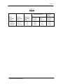
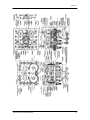
UNION SWITCH & SIGNAL
645 Russell Street
Service Manual 3151
Batesburg, SC 29006
FN-16 and FN-16A
Flasher Relays
Installation, Operation, and Maintenance
April, 1997
C-1/84-75-356-5
COPYRIGHT 1997, UNION SWITCH & SIGNAL INC.
PRINTED IN USA
An Ansaldo Signal Company
SM 3151
FN-16 and FN-16A Flasher Relays
2
SM 3151
FN-16 and FN-16A FLASHER RELAY
*********************************
This service manual covers information for shop repair adjustment and calibration of FN16 and FN -16A Flasher Relays with 2N-2R (now obsolete) and 4N-4R contacts.
The FN-16A differs from the FN-16 relay only in design of the lamp contacts, which
necessitates the use of a heavier armature counterweight, and in that the armature
supporting bracket is arranged to permit the armature to be assembled to the relay without
removing the contact springs from the armature. The lamp contacts on the FN-16 relay
were designed only for AC loads while the lamp contacts on the FN-16A relay may be
used for DC as well as AC lamp load. The operating coils are equipped with a rectifier for
suppression of radio interference originating in the self-operating contacts.
The operating mechanism is designed to provide minimum wear at the armature pivots
and core pins, thus assuring that the rate of contact operation (i.e. flashing rate) remains
above the AAR minimum value without any need of adjustment for many millions of
operations. Original timing can readily restored in the field, when required, by removing
one or more copper washers from the common core. The core and coil assembly is so
constructed that timing adjustments can be made without unsealing the relay or disturbing
the relay adjustments. All new and re-manufactured flasher relays have a minimum of six
(6) copper washers to allow for this field adjustments.
The flash rate on the FN-16 and FN-16A is 45-55 operations per minute. Prior to 1979
the flash rate was 40-45. The minimum flash was increase by AAR at that time.
1. OILING OF BUSHING HOLES AND PIVOTS
For oiling trunnion screw pivots and bushings in the armature, we recommend Special
Instrument Oil, US&S part number J-041099.
When using this oil the cap is turned carefully until free, and then with-drawing the
applicator rod, the rod shall be draw slowly across the edge of the bottle opening to
remove any excess oil. This rod shall be returned to the bottle without coming in contact
with any foreign material. It shall be wiped clean each time that there is suspicion of
contamination, and the bottle be closed promptly within its own cap.
IT IS VERY IMPORTANT THAT THE OILING BE PERFORMED AS FOLLOWS:
A.
The bushing holes in the armature shall be carefully examined to check
that they perfectly clean and free from dust.
B.
The bearing area of the pivot screws shall be thoroughly covered with oil
by means of the rod, the rod being withdrawn from the bottle in such a
manner as to leave a drop of oil on it. Since this non-spreading oil it
FN-16 and FN-16A Flasher Relays
3
SM 3151
should be placed directly on the surface to lubricated. After the oil drop
has been applied, the applicator rod should be wiped against the edge of
the bottle opening to remove the surplus drops. The rod should then be
used to distribute the drop of oil over the bearing area of the pivot screws.
Any excess oil on the pivots shall be removed by just touching it with a
lintless cloth. Care should be taken not to cover the should not threaded
portion of the screws with oil.
C.
Care shall be taken that the oiled parts are protected from dust from the
time of oiling until the relay is sealed.
2. ARMATURE
A.
The armature should be located centrally in the bracket; i.e. the distance
from the side of armature to the bracket should be the same at the front of
the relay as it is at the back, making allowance for the end play specified
in (2B).
B.
The end play of the armature should be not less than .010 in. nor more
than .015 in.
C.
The pivot screws should be tightened securely to bracket, and after the
armature air gap is set, the armature bracket should be tightened securely
to the central pole piece, and the hex head nuts and bolts locked with the
lock washers.
D.
The air gap in either extreme position should be set as closely as possible
to a parallel value of .015 in. At no point should the air gap be less than
.013 or no more than .017 in.
E.
The armature stop pins should strike as flatly as possible against the pole
faces.
F.
The total stroke of the armature should be checked to see that it is .106 in.
+/- .002 in. A convenient means for checking this is to use two separate
spacers .053 in. thick placed one between each stop pin and pole face and
at the inside edge of the stop pin.
3. CONTACT ADJUSTMENTS
A.
Before the contacts are adjusted, all screws holding contact supports and
contact members should be checked for tightness. A check of the lamp
control contact springs with wedge and flat tips and the relay control
springs with spherical faced tips should also be to see that they occupy
their correct relative position as shown in figures 1, 2 and 3. Spacer used
FN-16 and FN-16A Flasher Relays
4
SM 3151
under the armature stop pin during contact adjustment are to be held
firmly by pressure applied to the armature between the stop and the pivots
so as to bring the armature as close to the pole faces as play in the pivots
will permit.
B.
FN-16A relay lamp contacts shall be adjusted with a .028 in. spacer under
the stop pin on the opposite side of the relay. That is, the right-handed
lamp contacts are adjusted by means of a spacer on the left-hand side, and
visa versa. With this spacer the upper and lower tips shall be in line and
light barely perceptible between contact points. A .001 in. thinner spacer
shall allow the contacts to close. If necessary in order to obtain flasher
frequency it is permissible to adjust the contacts to just open with a .025
in. spacer and to close with a .024 in. spacer.
The contact springs and their stops shall be adjusted so that the springs have an initial
pressure against the stops of 16 to 25 grams on the 4N-4R contact relays and 30 to 32
grams on 2N-2R contact relays. The pressure shall be measured at the tip[s in a direction
perpendicular to the spring at the tips.
The stop shall be adjusted with its end as close as possible to the contact tips without
interfering with the normal movement of the contact spring.
The lamp contacts (with wedge to flat tips) shall make over at least 25% of the contact
line contact.
The minimum contact opening with contacts just making on the other side shall not be
less than .058 in.
FN-16 and FN-16A Flasher Relays
5
SM 3151
C.
FN-16 relay lamp contacts should be adjusted with a .036 in. spacer under
the stop pin on the opposite side of the relay. That is the right-hand lamp
contacts are adjusted by means of a spacer at the left-hand stop pin and
visa-versa. With this spacer the upper and lower contact tips should be in
line, and the light should barely be perceptible between the contact points.
A .001 in. thinner spacer should allow the contacts to close.
The minimum contact opening on the one side with the contacts just making on the other
side should not be less than .020 in.
D.
Operating contacts (FN-16 and FN-16A relays) should be adjusted with a
.041 in. spacer between the armature stop pin and the pole face on the left
side of the relay (as viewed from the front with the relay in the normal
position). The left operating contact should be adjusted so that light is
barely perceptible between the contact points and .040 in. spacer should
allow the contacts to close. After adjusting the left operating contact, the
right operating contact should be adjusted so that light is barely
perceptible between the contact points with a .060 in. spacer under the left
stop pin. A .061 in. spacer should the allow the right operating contact to
FN-16 and FN-16A Flasher Relays
6
SM 3151
close. This adjustment provides for .020 in. contact opening with either
operating contact just making.
E.
The flexible connectors should be dressed so that on the operation of the
armature there is no concentrated bending at any point, especially near
soldered ends. The flexing should be distributed as much as possible over
the whole length of the connectors. The flexible connectors shall not touch
the cover during operation after it is installed.
4. CONTACT RESISTANCE
A.
The contact resistance shall be measured on all contacts, with armature
against the stop pin . Resistance measured shall not exceed the values
given in the following table:
Contact surfaces
Silver to silver impregnated carbons
Silver to silver
Ohms
.05
.03
5. BACK STRAP
The back strap and tops of the cores should be clean and make good magnetic contact.
6. TIME PERIOD ADJUSTMENT
A.
After the contacts have been adjusted, the adjustment to obtain exact
timing shall be made as follows:
B.
Apply voltage as specified in table under “Timing Test Volts” for the
proper relay resistance to the coil terminals of the relay. Connect an “on
time meter” (Simpson TS-111 or equivalent) to the right hand lamp
contact and while relay is operating note the time of the closed circuit.
Then repeat the same test on a left hand lamp contact and compare the
readings. If the two time periods, i.e. armature movements, are not within
+/- 20%, adjust the air gap by moving the adjustable shunt by increasing
or decreasing the air gap between the shunt and the central pole piece to
obtain proper balance.
C.
Next count the number of operations per minute. Armature operations
shall be counted in cycles, i.e. a left and right operation as one operation.
Thus operations counted are the same as “Flashes per lamp per minute”.
D.
Adjust the timing to meet the requirements in Table under “Shop
Adjustments”.
FN-16 and FN-16A Flasher Relays
7
SM 3151
If necessary, copper washers on the common core may be removed or added for specified
flash rate. In no case shall the number of washers on the common core be less than 6 after
proper timing is obtained. A maximum of 29 washers may be used if required.
NOTE:
Original timing can be restored in the field, when required,
by removing copper washers from the common core.
In order to maintain the minimum required flash rate it is
permissible to have less than 6 washers.
However, when it becomes necessary to remove these washers
indicating wear, it is recommended the relay be shopped.
Union Switch & Signal recommends no less than three
washers to maintain minimum flash rate.
7. MINIMUM OPERATING VOLTAGE
After the timing adjustments, check that the relay starts to operate at the minimum
operating voltage for the proper relay resistance as given in Table 1.
8. CLEANING
A.
During Adjustment and Calibration extreme care should be taken to see
that no foreign matter is carried to the assembly by tools or spacers. After
adjustment is completed, the stop pins shall be cleaned by drawing a strip
of clean white bond paper between the stops and the pole faces. Spacers
shall not be used between the stop pins after final cleaning with paper.
B.
Before Sealing the Relay a careful inspection shall be to insure removal of
all dirt and loose particles from the inside of the relay.
FN-16 and FN-16A Flasher Relays
8
SM 3151
TABLE I
Shop Adjustment
Relay
Resistance
Ohms
4.5-4.5
200-200
500-500
Normal
Operating
Volts
1.0-1.2
6.8-8.0
10.0-12.0
FN-16 and FN-16A Flasher Relays
Minimum
Operating
Volts
0.9
6.0
8.5
Flashes
Per Lamp
Per Min.
48-55
48-55
48-55
Timing
Test
Volts
1.1
7.0
11.0
Nominal
Rating
Flashes
Per Lamp
Per Min.
45-55
45-55
45-55
9
SM 3151
FN-16 and FN-16A Flasher Relays
10
SM 3151
FN-16 and FN-16A Flasher Relays
2