1
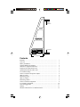
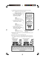
ON
/O
FF
Ca
lib
ra
te
0%
IN
/FT
HO
LD
Owner’s Manual
Adjustable
long standoff
Long standoff
ON/OFF
Calibrate 0%IN/FT
HOLD
Short knurled feet
Contents
Welcome ..................................................................................................
Overview .................................................................................................
Battery Installation ..................................................................................
Optional Hands-Free Adapter .................................................................
SmartTool - Digital Inclinometer ............................................................
Preparing the SmartCamber Tool ............................................................
Squaring Your SmartCamber Tool ..........................................................
Level Surface Setup ................................................................................
Non-Level Surface Setup/Zero Adjust ....................................................
What is Caster? .......................................................................................
Measuring Caster ....................................................................................
What is Camber? .....................................................................................
Measuring Camber ..................................................................................
Non-Level Surface Alignment ................................................................
Level Surface Alignment .........................................................................
Tips and Suggestions ...............................................................................
Options ....................................................................................................
Module Calibration for Use Without Frame ...........................................
1
1
1
2
3
4
4
4
5
6
6
8
8
9
10
11
11
12
Welcome!
Thank you for your purchase of our SmartCamber tool. You are now the
owner of what we believe is the best portable camber and caster measuring
tool available today. Both the occasional user and experienced race car
tuner will appreciate the simplicity of the SmartCamber tool and its ability
to give fast and accurate results.
We are proud of the fact that our SmartCamber tool is used by some of the
fastest car owners in the business. In addition, some of the largest
automakers in the world have purchased our tool to teach alignment
techniques in their technical training programs. If at any time you have a
question or suggestion, please do not hesitate to call.
Thank you,
Craig Watkins
Please be sure to see the optional parts
available to you later in this booklet on page 11.
Overview
The SmartCamber tool was designed to maximize its measuring potential
over a wide variety of wheel/tire combinations. Utilizing repeatable digital
technology, the tool allows accurate measuring regardless of where the
vehicle is or what angled surface it is on.
There is no misinterpretation with this tool because there are no bubbles or
lines to subjectively read. The SmartCamber tool takes all of the guess
work out of camber and caster measuring.
Since there are nearly an infinite number of wheel and tire combinations, it
was necessary to design a tool that would be quick and easy to use.
The number one design premise was to allow camber and caster to be
measured almost anywhere without removing hub caps, lug nuts or jacking
the car off of the ground.
Though it is basic in concept, the results are excellent. One fixed and one
adjustable standoff allows the owner to use the tool on almost any vehicle.
For toe adjusting - please see our website for our new SmartString tool.
Battery Installation: (Battery included)
Remove back cover. Attach 9-volt battery to terminals and replace the cover.
1
Optional Hands-Free Adapter
The Hands-Free adapter was developed to allow the SmartCamber tool to
be attached to the wheel so as suspension adjustments are made, the user
can then see the changes as they happen.
Camber angles can be just as easily measured with or without the HandsFree adapter in place; the performance of the tool is exactly the same.
However, the tool will have to be recalibrated for one or the other.
(See page 4, Calibrating SmartCamber tool)
Attaching the Hands Free Adapter
Unscrew the lower standoff (with the attached aluminum thumb wheel).
Hook the adapter over the bottom lip of the SmartCamber frame and swing
the adapter up against the bottom on the frame (Step 1).
With the 8-32 screw provided, thread and tighten the screw into the
Pemnut (Step 2).
Thread the long standoff into the far ends of the adapter as illustrated.
Step 1
Step 2
ON
/O
FF
Ca
lib
rat
e
0%
IN/
FT
HO
LD
ON
/O
FF
Ca
lib
rat
e
0%
IN/
FT
HO
LD
Note: 1. The SmartCamber tool will have to be recalibrated if the
Hands Free adapter is removed or installed or if the tool is
dropped. It should be checked periodically for calibration.
2. Calibration with the Hands-Free adapter is the same as with
just two long standoffs, except the small knurled screws on
the bottom will be in more extreme positions. To calibrate
follow the same steps on page 4.
2
SmartCamber - Digital Inclinometer
6 8 7
ON/OFF
1
9 10 6
Calibrate
3
4
°%IN/FT HOLD
5
2
Controls:
1 ON/OFF - If left idle for 6 minutes,
the SmartCamber tool will automatically shut off.
2
3
HOLD - Push to “freeze” and “unfreeze” display readings.
4
5
CALIBRATE (see Calibration procedures)
LISTEN & LEVEL AUDIO Push to activate and de-activate the
beeper. Beeper will sound at level and plumb.
° % in/ft - Push to change the display units: Degrees (°), Slope (%),
Pitch (in/ft).
Pitch readings are in 1/8 in/ft increments. Plus and minus signs indicate
when the pitch is slightly more (+) or slightly less (-) than the pitch shown
on the display.
Note: The ° % IN/FT button 5 can be used even when the display is in
HOLD. This feature is a convenient way to convert angles from one unit
to another.
6
UP/DOWN ARROWS - Left and right indicators point toward level
or plumb (whichever is closer). Indicators get shorter as the
SmartCamber tool gets closer to level (°), or plumb (90°).
7
LOW BATTERY - Low 9V battery indicator. Replace battery as soon
as possible. Battery life is typically 100 hours.
8 DIGITAL DISPLAY - Display readout of current measurement.
9 LISTEN & LEVEL AUDIO
10 ° % IN/FT MODES - Indicates measurement “mode”: Degrees (°),
Slope (%), Pitch (in/ft).
Note: Display reads right side up when the SmartCamber tool is upside down!
3
Preparing the SmartCamber Tool
Squaring the Frame (Fig 2, 3, and 4)
Squaring the tool is a procedure to adjust the bottom feet to be square to
the long standoffs. If the tool should happen to be mishandled, it should be
re-checked. A window works well as vertical surface.
1. Turn the SmartCamber tool ON .
2. Horizontal short feet adjust (fig 2). Place the SmartCamber tool on a
flat smooth surface (up to 7° from level). Wait 10 seconds. Push and
hold the CALIBRATE button, CAL1 will appear and then a flashing
number.
3. Rotate the SmartCamber tool end-for-end (fig 2). Push and hold the
CALIBRATE button, CAL2 will appear and then a number.
4. Plumb short feet adjust (fig 3). Place the SmartCamber tool against a
window with long feet up. Wait 10 seconds. Push and hold the
CALIBRATE button, CAL1 will appear and then a flashing number.
5. Move the SmartCamber tool to the other side of the window. Wait 10
seconds. Push and hold the CALIBRATE button, CAL2 will appear
and then a number.
6. Repeat steps 4 and 5 with the long feet down (fig 4). Now the
SmartCamber tool is calibrated for plumb.
7. Turn the SmartCamber tool OFF .
8. Put the SmartCamber tool up against window on it’s long feet (fig 5).
Press and hold CALIBRATE while pressing the ON button CAL2
will appear and then the number 0.
9. Now put the SmartCamber tool up against window on its short feet.
Adjust the short feet until tool reads 90°. Your frame is now square.
10.The SmartCamber frame is now square. Continue to calibrate the tool
for use.
Level Surface Setup (Fig 1)
1. Turn the SmartCamber tool ON .
2. Put SmartCamber tool up against the window on the long feet. Wait 10
seconds. Push and hold CALIBRATE button, CAL1 will appear then
a flashing number.
3. Go to other side of your vertical plane (visibly close as possible to the
same plane on the other side). Wait 10 seconds. Press and hold
CALIBRATE button, CAL2 will appear and then a number. This
number will read the same on either side of your verticle plane. Your
tool is now ready to be used on a level surface.
4
Non-Level Surface Setup/Zero Adjust (Fig 2, 3, 4 and 5)
1. Turn the SmartCamber tool ON .
2. Put the SmartCamber tool on a horizontal surface on it’s short feet
(fig 2). Wait 10 seconds. Push and hold the CALIBRATE button,
CAL1 will appear and then a flashing number. Rotate the tool 180°.
Push and hold the CALIBRATE button, CAL2 will appear and then
a number. You have set the tool to level.
Note: The tool can now be used for leveling the floor.
3. Plumb short feet adjust (fig 3 and 4). Place the SmartCamber tool
against a window with long feet up. Wait 10 seconds. Push and hold the
CALIBRATE button, CAL1 will appear and then a flashing number.
4. Move the SmartCamber tool to the other side of the window. Wait 10
seconds. Push and hold the CALIBRATE button, CAL2 will appear
and then a number.
5. Repeat steps 4 and 5 with long feet down (fig 4). Now the
SmartCamber tool is calibrated for plumb.
6. Turn SmartCamber tool OFF .
7. Put the SmartCamber tool on your non-level surface on it’s short feet.
Wait 10 seconds. Press and hold the CALIBRATE buttonwhile still
pressing the CAL button press and hold the ON button, CAL2 will appear
and then the number 0 this is called zero adjust. Your tool is now ready to
be used on a non-level surface. (You must do this step for each wheel).
Fig 3
ON/OFF
Calibrate 0%IN/FT
HOLD
Fig 1
Fig 4
ON/OFF
Calibrate 0%IN/FT
Calibrate 0%IN/FT
ON/OFF
HOLD
HOLD
To set horizon for long feet
To set plumb for short feet
Fig 2
Fig 5
ON/OFF
Calibrate 0%IN/FT
HOLD
Squaring frame
ON/OFF
Calibrate 0%IN/FT
HOLD
ON/OFF
To set horizon for short feet
Calibrate 0%IN/FT
HOLD
Adjust short feet to
achieve 90° reading
Be sure you are in the degree mode not percent or inches/foot mode.
5
What is Caster?
The caster angle is the inclination of the imaginary line the spindle pivots
around. Typically tipped towards the rear of the car. The caster angle
creates forces that result in the following:
First, they (the forces) return the wheels to the center-steer position after a
turn is made.
Second, they make the vehicle track straighter and more predictable.
Third, they increase or decrease the camber gain of the wheel, as it turns, to
help maximize the traction potential of the tire.
Note: High caster angles coupled with wide tires can make the steering
very heavy and hard to turn.
Measuring Caster
Caster is calculated by measuring the camber angle in two different
positions, and then putting those measurements into a simple formula.
To measure caster, do the following, but be sure to take your time the first
few times you do it:
1. Start with the left front wheel.
2. Place the layout template sheet (included) on the floor and use chalk (or
paint for permanent marking) to scribe lines that are about a foot longer
than the template. Then remove the template and connect the lines as
on the template.
3. Roll the car until the front wheel is on the centerline (CL) axis and
parallel to the X axis.
4. Turn the steering wheel until the left front wheel is parallel to the Z
axis.
5. Use a stiff piece of cardboard approximately 7”x18” as a “plane”
reference template (flat sheet metal is better), carefully put the plane on
the Z axis line and carefully lean the template against the tire. If it
touches the tire evenly, then the wheel is turned 20°.
6. Measure the camber angle in this position and note.
7. Steer the wheel back through the center-steer
position and parallel to the Y axis. Repeat the
plane template alignment method.
8. Measure the camber angle in this position
and note.
20°
Z
Y 20°
6
9. Calculate the caster angle using one of the following examples:
Note: 1. Example No. 2 is the most common.
2. What you are trying to achieve is camber difference from
turning left and right.
Note:
1. If both measurements are negative then
If
you
cannot
turn
Subtract the small number
-3 *
°
your
wheels
20
from the larger number
-1
determine
the
——
angle you can turn
Equals
2
both wheels. Note
Multiply 2 by 1.5 = 3
that number and
The wheel has 3° of caster.
use the
2. One negative and one positive, then
multiplication
Add the numbers together
-3 *
factor below. The
+1
——
procedure does not
Equals
4
change, however.
Multiply 4 by 1.5 = 6
Multiplication
The wheel has 6° of caster.
Factors
3. If both are positive, then
20° = 1.5
Subtract the smaller number +3 *
15° = 2.0
from the larger number
+1
——
10° = 3.0
Equals
2
* Ignore Negative and Positive
Multiply 2 by 1.5 = 3
symbols when adding and
The wheel has 3° of caster.
subtracting
10.Make whatever adjustments are required and remeasure until you have
the angle you want.
11. Repeat the same steps on the right front wheel.
12.Reset the toe (can be done with SmartRacing Products-SmartStrings).
Any changes to the caster or camber angles will have changed the toe
settings.
Left arrow up and right
arrow down equals
Positive Camber
ON/OFF
Calibrate ° % IN/FT
Left arrow down and right
arrow up equals
Negative Camber
HOLD
ON/OFF
Calibrate ° % IN/FT
HOLD
ON/OFF
ON/OFF
Calibrate ° % IN/FT
Calibrate ° % IN/FT
HOLD
HOLD
Tech Note:
It is helpful to put a temporary witness mark on the steering wheel
hub to the steering column (with tape), so you always return to the
same angle of reference. Also, zeroing the car is not necessary
because you are only interested in the difference in the camber in
the two positions.
7
What is Camber?
The inclination of the wheels from true vertical is commonly referred to as
“Camber”; read as either positive or negative.
Positive Camber: As viewed from the rear, the tops of the tires are further
apart than the bottom (very uncommon).
Negative Camber: As viewed from the rear, tops of the tires are closer
together than the bottom (very common).
Measuring Camber
1. Hold the SmartCamber tool against the wheel, which you are planning
on measuring, at the twelve and six o’clock position. Adjust the sliding
long standoff so it touches the wheel face near the edges (if the wheel
has a curved face, at the top of the wheel, put a piece of racer’s tape
with a dot on it so you will always measure from the same location).
Be sure the frame itself is not touching the tire.
Tech Tip: Small pieces of Racer’s tape placed where the
pins contact the wheel will help protect the wheel finish.
One of our customers suggested carburetor vacuum plugs,
a great idea!
Note: As with any tool, the more you use it, the easier it is
to use. The SmartCamber tool is no exception.
8
Non-Level Surface Alignment
Chances are, the surface that the car is sitting on is not flat or level. Even
very good concrete floors have small dips and valleys in them.
You will need three things:
•
A piece of 1.5” square aluminum box tubing (or long level) that is
about 6” wider than the track width of your car (mark one side of the
tubing with the words “Top Center”);
•
Two 1” sockets or equivalent (the idea is to have two round spacers
that are the same height).
•
Some 12” square smooth floor tiles for shims.
1. Position the car where it is to be aligned.
2. Mark the floor position of each tire with a pen or chalk.
3. Push the car back out of the way and put one socket where the center of
one tire was and one where the other front tire was.
4. Put the aluminum box tube or level (with the Top Center marking facing
upwards) on top of the two sockets.
5. Zero Adjust the tool as described earlier (page 5), this will need to be
done for each side of the car.
6. Measure camber.
Take these tools everywhere you go because even if you are on rough
crummy asphalt, this method will average out the surface and you will get
good, accurate camber readings.
9
Level Surface Alignment
Using this method, instead of resetting the tool to zero, you level the floor
to true horizon and you never reset the module. Once you have recalibrated
the module to true horizon (level) you simply measure each wheel
individually and note its readings.
You will need three things:
•
A piece of 1.5” square aluminum box tubing (or long level) that is
about 6” wider than the track width of your car (mark one side of the
tubing with the words “Top Center”);
•
Two 1” sockets or equivalent (the idea is to have two round spacers
that are the same height).
•
Some 12” square smooth floor tiles for shims.
1 As mentioned earlier, mark the four tire positions on the floor where
you plan to do your setups. Reset the module to level by following the
two step calibration procedures for Level on (page 5 fig 2).
2 Roll the car back and put the two sockets (or spacers) where the front
tires would be and lay down the aluminum box tubing (with the marked
“top center” up). Put the module in the center of the box tubing and
note the reading. If it reads zero, your floor just happens to be parallel
to true horizon and you should consider it your lucky day! If not, shim
the side that is low using 12” x 12” linoleum floor tiles (they’re about
.060” thick) until the module reads zero. Double check it by spinning
the module around so the display is facing the other direction; it should
still read zero.
3 Now move the spacers and tubing to where the rear tires would be and
repeat the process until the module reads zero.
Note: Mark the floor or a logbook so you know how many tiles to use
next time.
4 You can then check to see if the floor is level fore and aft by putting the
spacers and tubing where the left front and left rear tires would be and
check it. If it is way off (a couple of degrees), you should shim
accordingly. This is really only an issue if you’re checking the angle of
attack, corner weighting - or checking the CG position.
5 Push the car back into position and measure away!
6 Be sure to roll car back and forth after any changes to the camber and
re-check.
10
Tips and Suggestions
1. Keeping a log book for your car is a great idea. Noting all important
race information and suspension settings and how they have worked in
the past, is a real time saver. The next time you are setting up your car,
to run at the same track, you can reference those past settings and dial
them in.
2. Sometimes the long standoffs are not long enough for certain fender
shapes and configurations. We do have longer standoffs available for
you to order, or we can make a custom length for you. (See below)
3. On many cars, there is a location that is level and true to the car. This
location, if found, works great for “zeroing the module” to the plane the
vehicle is sitting on. This surface needs to run across from the right
side to the left side, not the length of the car front to rear.
4. Practice using your SmartCamber tool, the more you use it, the faster
and easier it will be to make changes.
5. The SmartCamber tool module is very sensitive (but not emotional!).
When measuring any angle, wait 3-5 seconds for the reading to
stabilize.
6. Some wheels have more run-out than others and give you erroneous
camber readings. To correct for this error, mark the top and bottom of
the wheel. Measure in that position. Spin the wheel half a turn and
remeasure. Take the average of those two readings and that will be
your true wheel angle.
Optional Parts
Besides the Hands Free adapter, please note the following:
1. Pro 360 module, measures full 360° with Alternate Zero setting feature.
Use part # 011021, sells for $226.95
2. Pro 3600 module, also measures full 360° with Alternate Zero setting
feature. It also has a RS-232 serial port connector so it can be attached
to a computer. Use part # 011031, sells for $329.00
3. 3.75” Standoffs. Use part # 011141, sell for $1.62 each
See our website at www.smartracingproducts.com for more information.
11
Module Calibration for Use Without Frame
Before your SmartCamber module can be used, the module (new or used)
must first be calibrated to itself. The calibration instructions are also on
the back of the module itself.
Procedure for Level
1. Turn the SmartCamber module ON .
2. Place the SmartCamber module on a flat smooth surface (table top).
Wait 10 seconds. Push and hold the CALIBRATE button, CAL1
will appear and then a flashing number.
3. Rotate the SmartCamber module end-for-end. Wait 10 seconds.
Push and hold the CALIBRATE button, CAL2 will appear and then
a number.
The SmartTool has now been calibrated for level.
Step 2
Step 3
ON/OFF
Calibrate 0%IN/FT
HOLD
ON
/O
FF
Ca
lib
ra
te
0%
IN
/FT
HO
LD
Step 3
ON/OFF
Calibrate 0%IN/FT
HOLD
Overhead Measuring for Level
If you need to read the display upside down, you must calibrate the top
surface of the angle finder. Repeat the steps described above except the
SmartCamber module should be upside down.
12
Procedure for Plumb
1. Turn the SmartCamber module ON .
2. Place the SmartCamber module against a flat vertical smooth surface
with the LCD display at the bottom, and away from the surface. Wait
10 seconds. Push and hold the CALIBRATE button, CAL1 will
appear and then a flashing number.
3. Rotate the SmartCamber module edge-for-edge along its long axis (i.e.
LCD display is still at the bottom, but is now against the flat vertical
surface.) The display should face away from you. Wait 10 seconds.
Push and hold the CALIBRATE button, CAL2 will appear and then
a number.
4. Repeat the steps above for plumb, except with LCD display at the top.
Now the SmartCamber tool is calibrated for plumb.
Step 2
Step 3
ON/OFF
Calibrate 0%IN/FT
ON/OFF
Calibrate 0%IN/FT
HOLD
HOLD
Step 4
If “CAL ALL” is displayed
1. This means that the tool is out of calibration.
2. Calibration must be done as explained in “Module Calibration for
Use Without Frame” page 12 and 13.
13