1
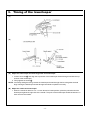
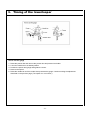
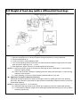
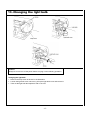
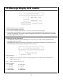
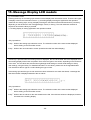
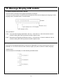
SERVICE MANUAL FOR
HOMELOCK
MODEL 929D
3. 1998.
CONTENTS
I
HOW TO USE THIS MANUAL .......................................................................... 1
II
HOW TO ADJUST ................................................................................................ 2
1.
2.
3.
4.
Height of needle bar ........................................................................................... 2
Position of the lowerlooper ................................................................................. 3
Timing of the lowerlooper ................................................................................... 4
Timing of the upperlooper .................................................................................. 7
5.1 Height of feed dog .............................................................................................. 9
5.2 Height of feed dog ............................................................................................ 10
6.
7.
8.
9.
Feed timing ...................................................................................................... 11
Height of presser bar ....................................................................................... 12
Thread tension adjustment .............................................................................. 13
Position of thread take-up ................................................................................ 14
10. Position of looper thread take-up ..................................................................... 14
11. Replacing the knives ........................................................................................ 15
12. Adjustment and replacement for the timing belt ............................................... 16
13. Changing the light bulb .................................................................................... 17
14. How to change the electronic parts .................................................................. 18
15. Message display .............................................................................................. 19
I. HOW TO USE THIS MANUAL
This service manual is compiled as a guide for the repair and service of Brother Homelock model 929D. Almost all
troubles or problems occurring on Homelock sewing machines which arise as the result of the user's lack of
knowledge or experience can be solved by following instruction book. It should be followed carefully because many
faults are caused by misuse or carelessness. We therefore recommend you to refer to the "Check list for better
sewing" in the Instruction Book before you attempt any adjustment from this manual.
However, if it is necessary to adjust the mechanism, use this manual together with the PARTS CATALOGUE for
each model. Find the fault in question in the Fault-finding chart and follow the corrective measures in this manual.
(1)
Adjust each model number circled in each illustration and instruction.
(2)
Symbols:
Move the part to its highest position
Move the part to its lowest position
Move the part to the extreme right
Move the part to the extreme left
Move the part to the right or left
Move the part up or down
-1-
II. HOW TO ADJUST......
1. Height of needle bar
1. Raise the needle to its highest position.
2. Loosen the screw on the needle bar.
3. Position the needle bar so that the clearance between the point of the needle and the surface of the
needle plate is as follows:
11.3 ~ 11.9 mm
NOTE: When making this adjustment, keep the needle bar at its highest position by holding the handwheel.
The long groove of the needle should face toward you.
PARTS CODE FOR GAUGE: X77402001
-2-
2. Position of the lowerlooper
Clearance between point of lowerlooper and upper surface of needle plate should be between 2.0 ~ 2.4 mm
when height of lowerlooper is at its highest position (or when distance between point of lowerlooper and
center of left-hand needle is 12.5 mm).
1. Before adjusting the timing, position the looper correctly.
2. Too much adjustment will cause damage to other parts or cause the needle to skip stitches.
How to use the gauge
1.
2.
3.
4.
5.
Temporarily attach the lowerlooper to the lowerlooper lever.
Turn the handwheel to position the point of the lowerlooper as far as possible to the left.
Remove the presser foot assembly.
Position the gauge as shown in the illustration.
Turn the handwheel until the point of the lowerlooper contacts the end of the gauge as shown. Remove
the gauge, turn the handwheel to expose the set screw and firmly tighten the screw. Finally, reposition
the gauge and check the final position of the lowerlooper.
6. Adjust the timing of the lowerlooper. (See page 4.)
-3-
3. Timing of the lowerlooper
(A)
(B)
(A) Adjust the lowerlooper thread through-feed and lowerlooper
1. Loosen set screw A and align the top surface of the lowerlooper thread through-feed with the top
surface of the lowerlooper.
2. Firmly tighten set screw A .
NOTE: Incorrectly setting the timing causes the lowerlooper thread through-feed to rub against the feed
dogs causing the lowerlooper thread through-feed knob to operate incorrectly.
(B) Adjust the needle and lowerlooper
1. When the needle is raised to 2.2 ~ 2.6 mm above its lowest position, place the pointed end of the
lowerlooper against the right side of the needle. The point of the lowerlooper should be between 0 ~
0.05 mm from the needle.
-4-
3. Timing of the lowerlooper
(C) (D)
(C) Adjust the needle and the movable needle guard
1. With the needle raised to 2.2 ~ 2.6 mm above its lowest position and the point of the lowerlooper
contacting the right side of the needle, check that the distance between the lowerlooper and the
movable needle guard is 1.2 ~ 1.5 mm and that the distance between the needle and the movable
needle guard is 0 ~ 0.1 mm.
2. In order to make an adjustment, loosen set screw D , move the movable needle guard upward,
downward, forward and backward to adjust it to meet the specifications described in 1.
3. Firmly tighten set screw D .
(D) Adjust the needle and the fixed needle guard
1. Before adjustment, remove the stitch tongue.
2. With the needle raised to 2.2 ~ 2.6 mm above its lowest position and the point of the lower looper
contacting the right side of the needle, check that the distance between the needle and the fixed
needle guard is 0 ~ 0.05 mm.
3. In oder to make the adjustment, loosen set screw E .
Rotate the fixed needle guard and move it forward and backward, then adjust it so it meets the
specifications described in 1.
NOTE: With the needle plate installed check that the fixed needle guard does not contact the needle.
4. Firmly tighten set screw E .
NOTE: Incorrectly setting the clearance between the needle and the lowerlooper, movable needle guard
and fixed needle guard can cause the needle to break or skip stitches.
-5-
3. Timing of the lowerlooper
How to use the gauge
1.
2.
3.
4.
5.
Raise the presser bar and remove the presser foot and presser foot holder.
Lower the needle bar to its lowest position.
Position the spacer and gauge and tighten the screw.
Remove the spacer.
Raise the needle bar until the needle clamp contacts the gauge. Continue making the adjustment
described on the previous page. (The spacer is 2.4 mm thick.)
-6-
4. Timing of the upperlooper
(A)
(OPTION)
(A) Timing of the upperlooper against the needle
1. Insert the upperlooper shaft as far as possible into the upperlooper.
2. Position the upperlooper to its extreme left position.
3. Loosen the looper lever fixing screw and position the upperlooper so that the clearance to the
pointed end to the left side of the needle is 5.6 ~ 6.0 mm.
4. Tighten the screw well.
NOTE: This clearance is for #14 needle.
-7-
4. Timing of the upperlooper
(B)
(C)
(B) Timing of the upperlooper in relation to the lowerlooper
1. Loosen the upperlooper screw.
2. Adjust the upperlooper not to bend the lowerlooper when the upperlooper travels nearest to the
lowerlooper.
NOTE: (a) When fastening the screw after adjustment, press the upperlooper slightly in order not to change
the corrected position.
(b) In case of bad timing, the upperlooper and the lowerlooper cross each other and do not work
correctly which will cause skipped stitches and loose tension.
(C) Setting the upperlooper lever to match the type of sewing selected
1. For two-thread sewing, lower the lever on top of the upperlooper as shown in the illustration.
(1) The lever should fit securely into the groove on top of the upperlooper after it has been moved
(lowered).
2. The lever should be returned to its original position after sewing is completed.
-8-
5.1 Height of feed dog Normal model (without a
differential feed dog)
1.
2.
3.
4.
Open the cloth plate and raise the feed dog to its highest position.
Set the sewing pitch at "3".
Loosen the set screw of the vertical adjusting shaft.
Turn the vertical adjusting shaft by the driver so that the clearance between the surface of the needle
plate and the upper surface of the feed dog is to 0.9 ~ 1.1 mm at the center.
5. After the adjustment, tighten the set screw of the vertical adjusting shaft well.
NOTE: (a) Stitches tend to pucker in fine fabrics, or the feed dog will touch the needle plate as the feed dog
reaches a higher position.
(b) The fabric will not be fed sufficiently or the feed dog will touch other parts like the looper as the
feed dog reaches a lower position.
(c) When adjusting the cut mark should be to your side.
-9-
5.2 Height of feed dog (with a differential feed dog)
(A)
(B)
(A) Adjustment for height of main feed dog
1. Open the cloth plate cover, and raise needle at its highest position by turning handwheel.
2. Set the sewing pitch at "3".
3. Loosen set screw of vertical adjusting shaft.
4. Turn vertical adjusting shaft by screw driver so that the clearance between upper surface of needle
plate and point of feed dog is 0.9 ~ 1.1 mm.
5. After adjustment, tighten set screw of vertical adjusting shaft securely.
NOTE: (a) Stitches will tend to pucker in fine fabrics or feed dog will touch needle plate, in case feed dog
reaches to higher position.
(b) Fabrics will not be fed sufficiently or feed dog will touch other parts like loopers, in case feed dog
reaches to lower position.
(c) When adjusting, cut mark on vertical adjusting shaft should be to your side.
(B) Adjustment for height of differential feed dog
Differential feed dog should be the same level as upper surface of needle plate when main feed dog
goes down and reaches the same level as upper surface of needle plate. Adjust by loosening set screw
of differential feed dog.
NOTE: (a) Adjust at position of "1.0" of feed ratio.
(b) Differential feed dog should not be inclined when tightening set screw of differential feed dog.
(c) In case difference between height of main feed dog and differential feed dog is too much, fabrics
will not be fed correctly
- 10 -
6. Feed timing
(Models)
The standard timing of the feeding: Main feed dog should be at the same level as upper surface of needle
plate when needle for overlocking goes down and point of it touches upper surface of needle plate.
As the overlock needle is descending and about to enter the needle plate hole, the feed dog must be
positioned at the surface of the needle plate.
NOTE: (a) Before the adjustment, check the Height of the feed dog and set the "Sewing pitch" at "3".
(b) Fabrics will not be fed straightly in case feed dog is inclined.
1. Open the cloth plate cover and loosen the set screws of the feed eccentric wheel by means of a
hexagonal wrench.
2. Turn the wheel and adjust the timing:
(a) In case of early timing, in other words when the feed dog is still positioned over the needle plate, turn
the wheel in direction A .
(b) In case of late timing, in other words when the feed dog is already positioned under the needle plate,
turn the wheel in direction B .
3. Tighten the set screws well.
- 11 -
7. Height of presser bar
Before adjustment, remove the panel assembly. Then turn the handwheel and raise the needle to its highest
position.
1. Raise the presser lever and loosen the screw securing the presser bar winding.
2. To adjust the height of the presser bar, raise the presser lever, and, at the point where the presser bar is
horizontal, raise or lower it until the first step is 4.8 ~ 5.0 mm above the needle plate. Make sure that the
presser lever does not come in contact with the upperlooper when it has been raised to the height of the
first step. Check also to make sure that the needle descents of the presser bar are not noticeably out of
alignment with the needle slots of the needle plate.
3. After the adjustment has been completed, tighten the screw securely that holds the presser bar winding
in place.
- 12 -
8. Thread tension adjustment
1. Set the thread tension dial to "4" on the dial scale.
2. Insert a plate of approx. 0.5 mm (0.02 in.) of thickness into the right side slot of the thread tension dial "4"
position on the dial scale and depress the notch of the dial clutch.
Then while holding the plate, turn the dial to adjust the thread
· Direction A : increase tension
· Direction B : decrease tension
- 13 -
9. Position of thread take-up
1. Lower the needle to its lowest position.
2. Loosen the set screw and position the thread take up below the thread retainer by 1.0 ~ 3.0 mm.
10. Position of looper thread take-up
1. Loosen the set screw of the thread take-up.
2. Position the looper thread take-up and thread guide above, holding the screws on the looper thread takeups at the distance shown in the illustration.
The position of the looper thread take-up A is as follows: turn the pulley and align the over-looper at the far
left. Loosen the set screw and align the right side of the looper thread take-up A at a position approximately
24.5 ~ 26.5 mm from the left side of the thread guide.
The position of the looper thread take-up B is as follows: turn the pulley and align the over-looper at the far
left. Loosen the set screw and align the right side of the looper thread take-up B at a position approximately
17 ~ 19 mm from the left side of the thread guide.
After making these adjustments, tighten the set screw securely.
- 14 -
11. Replacing the knives
If the knives are blunt, they will cause the fabric to pucker and uneven stitches.
NOTE: (a) If one strand of thread can be cut off in front of or at the rear of the knife, the knife is sharp
enough.
(b) When the knives are blunt, replace them with new ones in the manner mentioned below. But be
sure to disconnect the power first.
1. Replacing the upper knife
(1) Loosen the upper knife set screw, pull up the upper knife and remove it.
(2) Insert the new upper knife into the upper knife holder.
(3) Then turn the handwheel until the upper knife is lowered.
(4) When the upper knife is at its lowest point, the distance (in the front-to-back direction) from the top of
the blade farthest forward of the lower knife should be 1.2 ~ 1.7 mm from the position farthest
forward of the upper knife.
(5) Re-tighten the upper knife well. Securely tighten the upper knife set screw.
2. Replacing the lower knife
(1) Loosen lower knife set screw and remove lower knife.
(2) Attach new lower knife on lower knife holder, and set position so that point of knife is the same level
as upper surface of needle plate. Tighten it with lower knife set screw.
NOTE: It is important to adjust the alignment of the upper and lower knives to enable sharp cutting.
- 15 -
12. Adjustment and replacement for the timing belt
(A)
(B)
(A) 1. Turn the upper blade dial until the upper blade is positioned so that it cannot be used, then remove
the cloth plate cover.
2. Remove the presser lever.
3. Slide the belt cover downward to remove it.
4. Remove the motor cover.
(B) 5. Adjust the belt tension by moving the motor fastening bolt right and left so that the belt can be
pushed down 5.0 ~ 6.0 mm when applying a pressure of 500g.
NOTE: (a) When the belt is worn, replace it in the same manner.
(b) The motor holder and the oil pan should be parallel.
6. After adjustment, assemble the machine in the reverse order.
- 16 -
13. Changing the light bulb
Caution!
Always be sure to turn off the power before carrying out the following operation.
Changing the light bulb
· Remove the lamp cover as shown in the illustration.
· Loosen the light bulb cover set screw, pull up the light bulb cover and remove it.
· Take out the light bulb abd replace it with a new one.
- 17 -
14. How to change the electronic parts LCD models
1. Take off the rear cover.
2. Loosen the three set screws, and take off the insulation sheet and insulation cover.
1. Take off the front cover.
2. Loosen the six set screws and take off the key PC board.
- 18 -
15. Message Display LCD models
Immediately after turning on the power:
1. Enter the initial settings for the CPU.
2. See whether the board check mode is on, and if so, run the board check program.
3. See whether the test mode is on, and if so, bring up the test mode specifications selection screen. If the
machine is operating in normal mode, select the language depending on the E2PROM value, and display
the sewing style selection screen.
LCD Displays and Key Operations
· The Select Key is the A key and the Message Key is the B key. These are used as described below.
1. Sewing style selection screen
Immediately after turning on the power, and when the A key has been pressed on the information screen,
the sewing style selection screen is displayed, as shown below.
<Key Operations>
A key ... Displays the next selection number and sewing style name. If the last number is displayed, the
display returns to No. 1.
B key ... Shifts to the information screen.
<Selection styles>
1.
2.
3.
4.
4 - overlock
3 - overlock
Rolled edge
Narrow edge
5.
6.
7.
8.
Blind stitch
Pin tucks
Flat lock
Ribbon lock
- 19 -
15. Message Display LCD models
(1) Information screen
Pressing the B key on the sewing style selection screen displays the information screen. There are two types
of displays used on the information screen: (1) a scrolling display showing the application and operation
method for the sewing style, and (2) a display showing the set values of the thread tension dial (3 screens),
depending on the thickness of the cloth (lightweight, normal, or heavy). The cloth thickness switches in
sequence each time the B key is pressed.
3 Scrolling display of sewing application and operation method
<Key Operations>
A key ... Shifts to the sewing style selection screen. The selection number is the same as that displayed
before shifting to the information screen.
B key ... Shifts to the next information screen (thread tension dial set values display).
If the B key is pressed while the scrolling screen is displayed, the set values listed above are displayed when
two scrolling displays have been completed. There are three types of set values, depending on the thickness
of the cloth. The set values are switched from lightweight cloth settings to normal cloth settings to heavy
cloth settings, using the B key. For detailed information on set values, please refer to the appended table.
The character at the far right is a code indicating the type of cloth.
If the sewing style and the type of cloth which have been selected do not match the thread, a message like
that shown below is displayed instead of the set values.
<Key Operations>
A key ... Shifts to the sewing style selection screen. The selection number is the same as that displayed
before shifting to the information screen.
B key ... Shifts to the set values for the next thread tension dial. If the third set values are displayed, however,
this shifts to the scrolling display.
- 20 -
15. Message Display LCD models
Test Mode (language specification settings)
This test mode is used when the language specification is changed.
Turning on the power with the A and B keys pressed starts the test mode and displays the language number,
language name, and ROM version, as shown below.
<Key Operations>
A key ... Increments the language specification value by 1, and returns to 1 when the maximum value is
reached. Holding down the key activates the auto repeat function.
B key ... Decrements the language specification value by 1, and returns to 1 when the maximum value is
reached. Holding down the key activates the auto repeat function.
<Language Specification>
The value for the language specification is stored in the E2PROM. If no value (FFh) has been set in the
E2PROM, or if an incorrect value has been entered, English (01h) will be used as the default language.
<ROM Version>
The last character of the display is a code indicating the ROM version.
- 21 -
- 22 -
929D
H7120120