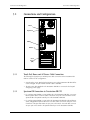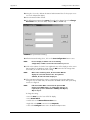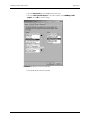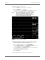
1
S e r v i ce M a n u a l
Datascope
Viewstation
0070-01-0665_revC.indd 1
™
3/10/10 5:38:13 PM
S e r v i ce M a n u a l
Datascope
Viewstation
™
Microsoft® and Windows® are US registered trademarks of Microsoft Corporation.
Spectrum OR™ is a U.S. trademark of Mindray DS USA, Inc.
Viewstation OR™ is a U.S. trademark of Mindray DS USA, Inc.
Copyright © Mindray DS USA, Inc., 2008. All rights reserved. Contents of this publication may not be reproduced in any
form without permission of Mindray DS USA, Inc.
0070-10-0665
Viewstation OR™ Service Manual
Table of Contents
Foreword ....................................................................................................................................................... v
Warnings, Precautions and Notes..................................................................................................................... v
Warnings ...................................................................................................................................................... vi
Precautions .................................................................................................................................................... vii
How To Get Help............................................................................................................................................ vii
Instrument Description ...................................................................................................... 1 - 1
Introduction .................................................................................................................................................... 1 - 2
Overview ............................................................................................................................................... 1 - 2
Core Functions ........................................................................................................................................ 1 - 2
Connectivity............................................................................................................................................ 1 - 3
Viewstation OR Block Diagrams........................................................................................................................ 1 - 4
Basic Configuration ................................................................................................................................. 1 - 4
Multiple Display Configuration .................................................................................................................. 1 - 5
System Modules, Components, and Peripherals .................................................................................................. 1 - 5
Viewstation OR CPU ................................................................................................................................ 1 - 5
Keyboard, Video, and Mouse/Touch Pad (KVM) Extender............................................................................ 1 - 5
Network Switches.................................................................................................................................... 1 - 6
Mouse/Touch Pad ................................................................................................................................... 1 - 6
Displays ................................................................................................................................................. 1 - 6
Supplied ELO-Compatible Touch Screen Display ................................................................................. 1 - 6
Customer Supplied Compatible Displays ............................................................................................ 1 - 6
Theory of Operation........................................................................................................................................ 1 - 7
CPU....................................................................................................................................................... 1 - 7
Motherboard .......................................................................................................................................... 1 - 8
Motherboard connections via PCI and AGP connectors ........................................................................ 1 - 8
System Hard Drive................................................................................................................................... 1 - 8
CD-ROM Drive ........................................................................................................................................ 1 - 8
AGP Graphics Dual Display Card ............................................................................................................. 1 - 8
ATX Power Supply ................................................................................................................................... 1 - 8
3.5 inch Floppy Drive .............................................................................................................................. 1 - 8
Independent Display ................................................................................................................................ 1 - 8
Repair Information ........................................................................................................... 2 - 1
Introduction .................................................................................................................................................... 2 - 2
Safety Precautions........................................................................................................................................... 2 - 2
Equipment and Special Tools Required .............................................................................................................. 2 - 2
Troubleshooting .............................................................................................................................................. 2 - 3
Disassembly Instructions................................................................................................................................... 2 - 6
Cover Removal........................................................................................................................................ 2 - 6
Front Panel Removal................................................................................................................................. 2 - 6
Power Supply Removal ............................................................................................................................. 2 - 6
AGP Video Board Removal....................................................................................................................... 2 - 6
Auxiliary Fan Removal ............................................................................................................................. 2 - 6
System Hard Drive Removal ...................................................................................................................... 2 - 6
Floppy Drive and Disclosure Hard Drive(s) Removal ..................................................................................... 2 - 6
CD-ROM Drive Removal ........................................................................................................................... 2 - 7
Motherboard Removal.............................................................................................................................. 2 - 7
Re-assembly Instructions ................................................................................................................................... 2 - 8
Motherboard Assembly ............................................................................................................................ 2 - 8
AGP Video Board Assembly ..................................................................................................................... 2 - 8
Power Supply Assembly ........................................................................................................................... 2 - 8
Floppy Drive ........................................................................................................................................... 2 - 8
CD-ROM Drive and System Hard Drive ...................................................................................................... 2 - 8
Viewstation OR™ Service Manual
0070-10-0665
i
Table of Contents
Auxiliary Fan .......................................................................................................................................... 2 - 9
CMOS Battery Replacement...................................................................................................................... 2 - 9
Closing the Unit....................................................................................................................................... 2 - 9
Rebooting and Testing the System.............................................................................................................. 2 - 9
Parts Replacement ............................................................................................................ 3 - 1
Introduction .................................................................................................................................................... 3 - 2
Available Replacement Parts and Assemblies ..................................................................................................... 3 - 2
Product Variations........................................................................................................................................... 3 - 2
Exchange Program.......................................................................................................................................... 3 - 2
Parts Pricing Information .................................................................................................................................. 3 - 2
Ordering Information ...................................................................................................................................... 3 - 3
Preventative Maintenance................................................................................................. 4 - 1
ELO Compatible Touch Screen Displays............................................................................................................. 4 - 2
Care and Cleaning of an LCD Display ....................................................................................................... 4 - 2
Care and Cleaning of a Touch Screen ....................................................................................................... 4 - 2
Viewstation OR CPU ....................................................................................................................................... 4 - 3
Cleaning ................................................................................................................................................ 4 - 3
Visual Inspection ..................................................................................................................................... 4 - 3
Fans....................................................................................................................................................... 4 - 3
Motherboard Backup Battery Replacement.................................................................................................. 4 - 3
Viewstation OR Network.................................................................................................................................. 4 - 3
System Maintenance ....................................................................................................................................... 4 - 4
Preventative Maintenance ......................................................................................................................... 4 - 4
Connections and Configuration ......................................................................................... 5 - 1
Hardware Installation Parts .............................................................................................................................. 5 - 2
Connections and Configuration ........................................................................................................................ 5 - 3
Touch Pad, Mouse and AC Power Cable Connection................................................................................... 5 - 3
Spectrum OR Connection to Viewstation OR CPU ........................................................................................ 5 - 3
Display Connection to Viewstation OR CPU ................................................................................................ 5 - 4
Single Display ................................................................................................................................. 5 - 4
Two Displays .................................................................................................................................. 5 - 4
Spectrum OR Communication Configuration ............................................................................................... 5 - 5
Appendix A ...................................................................................................................... 6 - 1
Installing Viewstation OR Software.................................................................................................................... 6 - 2
Introduction............................................................................................................................................. 6 - 2
Required Parts and Equipment .......................................................................................................... 6 - 2
Prerequisites ................................................................................................................................... 6 - 2
Software Installation................................................................................................................................. 6 - 2
Appendix B ...................................................................................................................... 7 - 1
CMOS Setup/Verification................................................................................................................................ 7 - 2
BIOS SETUP Pentium 4 Motherboard ......................................................................................................... 7 - 2
Independent Display Functional Requirements..................................................................................................... 7 - 7
Electrical Requirements ............................................................................................................................. 7 - 7
Power Supply ................................................................................................................................. 7 - 7
Display Resolution ........................................................................................................................... 7 - 7
Display Aspect Ratio ........................................................................................................................ 7 - 7
Color Support ................................................................................................................................. 7 - 7
Image Brightness ............................................................................................................................. 7 - 7
Image Contrast ............................................................................................................................... 7 - 7
Viewing Angle ................................................................................................................................ 7 - 7
Mechanical Requirements ......................................................................................................................... 7 - 8
ii
0070-10-0665
Viewstation OR™ Service Manual
Table of Contents
Connectors (Cable Termination at the Viewstation OR PC) .................................................................... 7 - 8
Mounting ....................................................................................................................................... 7 - 8
Environmental and Agency Requirements.................................................................................................... 7 - 8
Compliance .................................................................................................................................... 7 - 8
Viewstation OR™ Service Manual
0070-10-0665
iii
Table of Contents
This page intentionally left blank.
iv
0070-10-0665
Viewstation OR™ Service Manual
Foreword
Introduction
Foreword
The Viewstation OR Service Manual is a guide for technically-qualified personnel who
perform maintenance and/or repair on the Viewstation OR and its Ethernet network.
This manual conveys system-wide information that is divided into sections. For quick
reference, each chapter’s title page displays a table of contents that indicates, sectionally, the
topics covered.
This publication may have been updated to reflect product design changes and/or manual
improvements.
NOTE:
Unauthorized servicing may void the remainder of the
warranty. Check with the factory or with a local authorized
Service Representative to determine the warranty status of
a particular instrument.
Warnings, Precautions and Notes
Please read and adhere to all warnings, precautions, and notes listed here and in the
appropriate areas throughout this manual.
A WARNING is provided to alert the user to potential serious outcomes (death, injury, or
serious adverse events) to the patient or the user.
A CAUTION is provided to alert the user signaling that special care is necessary for the
safe and effective use of the device. They may include actions to be taken to avoid effects on
patients or users that may not be potentially life threatening or result in serious injury, but
about which you should be aware.
A NOTE is provided when additional general information is applicable.
Viewstation OR™ Service Manual
0070-10-0665
v
Introduction
Warnings
Warnings
WARNING: Do not attempt to use the Viewstation OR, including cabling
for any purpose other than its intended use.
WARNING: Route cables neatly. Ensure cables are not in the way of
patient or hospital personnel.
WARNING: Loading any unauthorized software including utilities on the
Viewstation OR will cause the application to no longer be
suitable for medical patient monitoring use.
WARNING: Do not connect or attempt to connect or reconfigure any
equipment to the Viewstation OR unless Mindray DS USA,
Inc. has explicitly approved the hardware in writing. This
includes all commercially available networking hardware
i.e., switches, routers etc.) or peripherals (i.e., Printers) even
if they are the same brand as recommended by the
configuration of the system and supplied by Mindray DS
USA, Inc.
WARNING: Do not attempt to load any devices or device drivers onto
the Viewstation OR. If the user connects or attempts to
connect any equipment to the Viewstation OR, it may not
operate as intended.
WARNING: Only qualified and trained Service Personnel should attempt
to service the equipment. Service is defined as any activity
requiring the cover to be removed for internal adjustments,
parts replacements, repairs or software upgrades of any
kind to insure compatibility.
WARNING: To insure compatibility with the operating system and
applications software, use only supplied and/or approved
components to repair any part of the Viewstation OR. Use
of unauthorized software, devices, accessories, or cables
other than those approved may render the application
unsuitable for medical patient monitoring. It may also result
in increased electromagnetic Emissions or decreased
Immunity of the system.
WARNING: All of the equipment on the Viewstation OR network must
utilize the hospital emergency power system. Failure to do
so will result in loss of monitoring during extended periods
of power failure.
WARNING: Do not put MPSOs (Multiple Portable Socket Outlets, i.e.,
multiple outlet extension cords) used with the Viewstation
OR on the floor. Do not overload MPSOs. Use only MPSOs
that comply with the requirements of IEC 60601-1-1.
WARNING: Do not clean the display while it is ON and/or plugged in.
WARNING: Disconnect AC power prior to any disassembly.
vi
0070-10-0665
Viewstation OR™ Service Manual
Precautions
Introduction
Precautions
CAUTION:
This system is intended for use in a hospital or clinical
setting and to be operated by trained and authorized
personnel who are acting on the orders of a physician. Its
purpose is the real time monitoring of a patient's
physiological parameters.
CAUTION:
For proper operation do not obstruct the fan air holes.
CAUTION:
For proper operation never place fluids on top of this
equipment. In case of accidental spillage, wipe clean
immediately and have the system serviced to ensure no
hazard exists.
CAUTION:
For proper operation, do not use any components of the
Viewstation OR network with a frayed or damaged power
cord.
CAUTION:
Do not operate the Viewstation OR or any of its components
if they have been dropped or the case has been damaged.
CAUTION:
Use only the supplied power cords. If a substitute is
necessary, only use Hospital Grade power cords.
CAUTION:
For proper operation use only approved accessories with
this product.
CAUTION:
Dispose of single use items in accordance with hospital
policy.
CAUTION:
Proprietary software is written directly to some of the PC
boards within the CPU. Replacement of the PC boards with
off-the-shelf PC boards may compromise the proper
operation of the Viewstation OR.
How To Get Help
Mindray DS USA, Inc. maintains a worldwide network of Sales, Clinical, and Service
representatives.
For U.S., Canada, and Latin America please contact:
Mindray DS USA, Inc.
Sales Tel: (800) 288-2121
800 MacArthur Blvd.
Sales Fax: (800) 926-4275
Mahwah, NJ 07430
Sales Tel: (201) 995-8237
Sales Fax: (201) 995-8659
Service Tel: (800) 288-2121
Service Fax: (201) 995-0119
For International Offices, refer to the contact information at the end of this service manual.
Viewstation OR™ Service Manual
0070-10-0665
vii
Introduction
How To Get Help
This page intentionally left blank.
viii
0070-10-0665
Viewstation OR™ Service Manual
1.0
Instrument Description
1.1 Introduction .............................................................................. 1-2
1.2 Viewstation OR Block Diagrams ............................................... 1-4
1.3 System Modules, Components, and Peripherals ........................ 1-5
1.4 Theory of Operation ................................................................. 1-7
Viewstation OR™ Service Manual
0070-10-0665
1-1
Introduction
1.1
Instrument Description
Introduction
This section of the service manual initially provides a high-level overview of the Viewstation
OR network, followed by more detailed information.
1.1.1
Overview
The Viewstation OR network is a comprehensive patient care monitoring system designed for
use in a hospital setting. The system is intended to be installed and used in a fixed, nonportable, permanent location that serves as a secondary viewing station. The Viewstation OR
network consists of the following modules:
• Viewstation OR CPU
• Spectrum OR Bedside Monitor
• Independent Display
• Proprietary Ethernet Network
Hardware and software components within each module provide system-wide functionality
and connectivity.
The monitoring capacity of the system is one Spectrum OR that is connected to the
Viewstation OR CPU through the Ethernet network.
This service manual focuses on the Viewstation OR and Ethernet modules. The Viewstation
OR is a combination of both hardware (e.g., CPU and display) and software components
(i.e., Viewstation OR software application).
1.1.2
Core Functions
The Viewstation OR is capable of displaying the following digital physiological parameters
as monitored by the Spectrum OR:
1. Heart Rate (BPM)
2. SpO2 (%SAT)
3. 4 Invasive Blood Pressures (SYS/DIA/Mean)
4. Non-Invasive Blood Pressure (SYS/DIA/Mean)
5. Two Temperatures
6. Respiration Rate (RR)
7. Inspired/Expired CO2
8. CO
9. CI
10. CCO
11. CCI
12. SvO2
13. PAWP
1-2
0070-10-0665
Viewstation OR™ Service Manual
Instrument Description
Introduction
The Viewstation OR is capable of displaying the following waveforms as monitored by the
Spectrum OR:
1. Up to seven waveforms of ECG (dependent upon the ECG lead set that is being utilized)
2. Up to four waveforms of Invasive Blood Pressure
3. One waveform of Pulse Oximetry (SPO2)
4. One waveform of Respiration
5. One waveform of CO2
• The maximum number of waveforms displayable is 12 and the minimum number is 3.
• Waveforms are acquired externally from the Spectrum OR™ and then presented to the
Viewstation OR either directly by a crossover Ethernet cable or through an Ethernet
switch via the E-LAN Protocol.
1.1.3
Connectivity
The Viewstation OR network is a single channel system that is designed for displaying patient
data that is received from a Spectrum OR™ monitor via an Ethernet network.
Viewstation OR™ Service Manual
0070-10-0665
1-3
Viewstation OR Block Diagrams
1.2
Instrument Description
Viewstation OR Block Diagrams
The following block diagrams illustrate wired configurations for the Viewstation OR network.
1.2.1
Basic Configuration
The basic configuration is a network of devices that transmits patient data from a Spectrum
OR™ monitor to a single, independently configurable display.
As depicted in Figure 1-1, the basic configuration of the Viewstation OR is:
• Spectrum OR Monitor
• Viewstation OR computer (CPU)
• Independent Display
• Touch Pad
INDEPENDENT
DISPLAY
TOUCH PAD
SPECTRUM OR
MONITOR
CPU
FIGURE 1-1 Basic Components of the Viewstation OR
The basic configuration can be varied to include two identically configured displays per
Viewstation OR computer and may also access the Spectrum OR monitor through an Ethernet
network switch (see Figure 1-2).
1-4
0070-10-0665
Viewstation OR™ Service Manual
Instrument Description
1.2.2
System Modules, Components, and Peripherals
Multiple Display Configuration
SPECTRUM OR
MONITOR
ELAN
ETHERNET
TO PANORAMA PATIENT
MONITORING NETWORK
OR GATEWAY
8 PORT
SWITCH
CPU
CPU
VIDEO
SPLITTER
CPU
VGA
TOUCH SCREEN
VGA
INDEPENDENT
DISPLAY
TOUCH PAD
INDEPENDENT
DISPLAY
INDEPENDENT
DISPLAY
TOUCH PAD
FIGURE 1-2 Example Multiple Display Configuration of the Viewstation OR
1.3
System Modules, Components, and Peripherals
1.3.1
Viewstation OR CPU
The application software and the Windows® XP Embedded operating system reside on the
system hard drive within the Viewstation OR CPU.
Independent displays provide a graphic display of patient waveforms and other data.
1.3.2
Keyboard, Video, and Mouse/Touch Pad (KVM) Extender
• The KVM Extender is used when displays, keyboard and mouse/touch pad are not
located in the same room as the Viewstation OR. The KVM Extender consists of a
transmitter and receiver connected via CAT5 cable.
• The transmitter is located with the Viewstation OR CPU, and the receiver is located with
the independent display. Data signals are carried by CAT5 Ethernet cable and link the
Viewstation OR CPU with the display(s).
NOTE:
Viewstation OR™ Service Manual
Both the transmitter and the receiver require a 110 VAC
connection.
0070-10-0665
1-5
System Modules, Components, and Peripherals
Instrument Description
• The extenders can be separated by a maximum of 400 ft. (122 m.) cable distance with a
screen resolution of 1280 x 1024.
1.3.3
Network Switches
• An Ethernet switch is used if there are multiple Spectrum ORs on the network or if there is
more than one Viewstation OR CPU connected to the Spectrum OR.
• The switch routes data from the Spectrum OR™ to all Viewstation OR CPUs on the
network.
• The switch can be the Panorama E-LAN switch or an independent switch dedicated to
the Viewstation OR network.
1.3.4
Mouse/Touch Pad
• The mouse/touch pad enables changes to be made on the Independent Display.
• The mouse/touch pad is connected to the KVM receiver via the PS2 mouse connector.
1.3.5
Displays
1.3.5.1
Supplied ELO-Compatible Touch Screen Display
• A Surface Acoustical Wave (SAW) touch screen is supported as the standard input device
on the 19” display.
• The touch screen operates independent of a mouse or touch pad interface.
• The actual touch screen and its controller are integrated into the display.
• The touch screen communication is accepted by Viewstation OR via a serial port.
• Use of the touch screen does not preclude the use of a mouse or touch pad.
1.3.5.2
Customer Supplied Compatible Displays
• See Appendix B or contact Customer Support for requirements.
1-6
0070-10-0665
Viewstation OR™ Service Manual
Instrument Description
1.4
Theory of Operation
Theory of Operation
The system design is based on an ATX computer architecture. Basic system data processing
configuration includes an ATX computer, an Independent Display with Mouse/Touch Pad,
and an Ethernet distribution network.
CAUTION:
1.4.1
Proprietary software is written directly to some of the PC
boards within the CPU. Replacement of the PC boards with
off-the-shelf PC boards may compromise the proper
operation of the Viewstation OR.
CPU
Each of the Viewstation OR CPU hardware items (e.g., hard drives, controls, etc.) are
identified below. The hardware is marked with labels identifying all connections.
7
1
U
8
U
U
2
U
3
9
U
4
U
10
U
U
11
5
U
12
6
U
U
REAR
FRONT
FIGURE 1-3 Viewstation OR CPU (Internal Side View)
1. ATX Power Supply
7. CD-ROM Drive
2. Microprocessor/Heat Sink/Fan
8. Memory Modules (2)
3. 12V power input
9. ATX Power Connector
4. AGP Video Card
10. System Hard Drive
5. PCI 1 (not used)
11. IDE 1 connector
6. PCI 2 (not used)
12. IDE 2 connector
Viewstation OR™ Service Manual
0070-10-0665
1-7
Theory of Operation
1.4.2
Instrument Description
Motherboard
The motherboard is the physical platform on which the computer’s electronic circuitry and
processors reside. The computer’s microprocessor is docked on the motherboard. The
microprocessor executes the application software. The following components also reside on
the motherboard:
• Random Access Memory (RAM)
• Read Only Memory, Basic Input/Output System (ROM BIOS)
• Associated Processing Logic
• EIDE controller for 3.5” floppy drive and system hard drives
• Mouse/touch pad and keyboard controllers
• Network Interface Ports
• Comm Ports
1.4.2.1
Motherboard connections via PCI and AGP connectors
• Serial Interface Comm Ports
• AGP Graphics Display Card
1.4.3
System Hard Drive
The system hard drive stores the Operating System (Windows XPE®) and Viewstation OR
application software. (It is controlled by EIDE controller circuitry on the motherboard.)
1.4.4
CD-ROM Drive
The CD-ROM drive is used to load software and to copy error logs. (It is controlled by EIDE
controller circuitry on the motherboard.)
1.4.5
AGP Graphics Dual Display Card
The AGP Graphics Display card sits in the J19 slot on the motherboard.
1.4.6
ATX Power Supply
The ATX switching Power Supply provides power for all electronic assemblies within the
Viewstation OR CPU. Regulated voltages are +5, -5, +12, and -12 Volts. The power supply
has a universal AC input and is rated for 460 Watts (minimum).
1.4.7
3.5 inch Floppy Drive
This drive is installed in the system but is not currently used for any applications.
1.4.8
Independent Display
All text and graphics are presented on an Independent Display that utilizes an external AC
power supply. Graphics information is transmitted through a graphics cable from an AGP
Graphics Card. The Independent Display follows the specifications detailed in section 7.2,
“Independent Display Functional Requirements”.
1-8
0070-10-0665
Viewstation OR™ Service Manual
2.0
Repair Information
2.1 Introduction .............................................................................. 2-2
2.2 Safety Precautions .................................................................... 2-2
2.3 Equipment and Special Tools Required ...................................... 2-2
2.4 Troubleshooting ........................................................................ 2-3
2.5 Disassembly Instructions ........................................................... 2-6
2.6 Re-assembly Instructions .......................................................... 2-8
Viewstation OR™ Service Manual
0070-10-0665
2-1
Introduction
2.1
Repair Information
Introduction
This section provides the necessary technical information to perform repairs to the system.
The most important prerequisites for effective troubleshooting are a thorough understanding
of the system functions and the theory of operation. If necessary, refer to the appropriate
Viewstation OR Operating Instructions Manual (P/N 0070-00-0663-01), which describes
instrument functions and features in full detail.
2.2
Safety Precautions
In the event the instrument covers are removed, make certain you observe the following
warnings and general guidelines:
• Do not short component leads together.
• Observe proper ANTI-STATIC precautions.
2.3
Equipment and Special Tools Required
You will need the following equipment and/or special tools when performing repairs on the
system:
• Anti-Static Wrist Strap
• Anti-Static Mat
• #1 Phillips Screwdriver
• #2 Phillips Screwdriver
• Slotted Screwdriver
• Laptop Computer with 100MB Network Interface Card
(used for network troubleshooting)
2-2
0070-10-0665
Viewstation OR™ Service Manual
Repair Information
2.4
Troubleshooting
Troubleshooting
Prior to troubleshooting a network problem, check the following areas:
• All AC and DC power connections are secure.
• All Ethernet cable connections are secure.
• Affected cable runs should be tested with a cable tester for continuity.
• IP addresses
• Valid IP addresses should be verified for all devices on the Panorama Patient
Monitoring Network.
• Bedside monitor configuration
• Network configuration should be verified within the monitor’s installation menu. Refer
to ‘‘Spectrum OR Communication Configuration’’ on page 5-5 of this service manual.
• Viewstation OR configuration
• Patient and IP address configuration should be verified
The display or the Viewstation OR CPU does not come ON
1. Verify the power LED on the display is ON. (This is usually located on the front panel.)
2. On LCDs, turn OFF the power switch and turn it back on. Verify the logo is briefly
displayed. If the No Signal message is displayed on the screen, no video signals are
reaching the display.
3. Verify that the cable between the display and the CPU is making a good connection,
that the connector screws are tight, and pins on the connectors are straight.
• If the problem persists, it is likely due to a problem within the CPU.
4. Verify that AC power switch is ON at the Viewstation OR CPU.
5. Reboot the Viewstation OR CPU. Verify that the power and hard drive LEDs are
illuminated and the fans are operating.
• If the display still does not come ON, the problem is likely within the CPU.
• If the hard drive LED does not illuminate, the problem is likely related to the CPU or the
motherboard.
• If the fans are not operating, the problem is likely the power supply.
Viewstation OR™ Service Manual
0070-10-0665
2-3
Troubleshooting
Repair Information
The display comes ON but the Viewstation OR CPU does not
complete “self-test”
Note the point at which the self-test stopped (e.g., passed through the memory check, CMOS
check, Drive check). Depending on where it stopped this may mean replacement of the
motherboard, memory chip or the hard drive is necessary.
The unit went through self-test, but did not get to the Viewstation
OR operating screen. It stays at the blue screen - no desktop icons
Clear the error and event logs (contact a Service Representative for instructions) and save the
config tool.
The mouse/touch pad does not function
1. Verify that the connections at the rear of the Viewstation OR CPU are secure and that
they are in the appropriate locations.
2. Check connections to the KVM Extender (Transmitter & Receiver).
3. Re-power the KVM Extender by disconnecting AC power from the transmitter and
receiver.
4. Reboot the system. Is the mouse functional?
• If not, install a new PS2 touch pad mouse and reboot the system again.
5. Is the touch pad mouse functional now?
• If not, this may mean replacement of the Mother PCB.
No touch screen response (only on supplied touch screen displays)
1. Verify that the connections at the rear of the CPU are secure and that they are in the
appropriate locations.
2. Check connections to the KVM Extender (Transmitter & Receiver).
3. Power cycle the KVM Extender by disconnecting AC power from the transmitter and
receiver and then reconnecting the AC power.
4. Clean the touch screen panel.
5. Reboot the system. Is the touch screen functional?
• If not, this may mean replacement of the touch screen display or the touch screen
controller card.
2-4
0070-10-0665
Viewstation OR™ Service Manual
Repair Information
Troubleshooting
Network Communication Loss From a Spectrum OR™ Monitor
1. Verify that the Ethernet connections between the Viewstation OR CPU and the Spectrum
OR are secure. Verify that the LEDs on the network port of the Viewstation OR CPU are
illuminated as follows:
• left-hand LED - continuously ON
• right-hand LED - flashing
2. If the connection between the Spectrum OR and the Viewstation OR CPU is a direct
connection via a crossover Ethernet cable, verify that the cable connection is secure.
3. If the connection between the Viewstation OR CPU and the Spectrum OR uses an
Ethernet switch:
• Verify that the cable connections between the Ethernet switch and the Viewstation OR
CPU are secure.
• Verify that the cable connections between the Ethernet switch and the Spectrum OR are
secure.
• Power cycle the Ethernet switch.
• Verify that the Power LED on the Ethernet switch is illuminated.
• Each port on the Ethernet switch has a corresponding Port Status light that
indicates that the cable connection has been established. For each cable that is
connected to the Ethernet switch, verify that the corresponding Port Status light is
illuminated. If the Port Status light is not illuminated, plug the cable into an
available port and verify that the Port Status light for this new port is illuminated.
4. Verify that the LEDs on the Comm Port of the Spectrum OR are illuminated as follows:
• Yellow LED - continuously ON
• Green LED - flashing
If either LED is not illuminated, it may indicate that the Comm Port is defective.
Viewstation OR™ Service Manual
0070-10-0665
2-5
Disassembly Instructions
2.5
Repair Information
Disassembly Instructions
This section provides information to assist the technician in disassembly and removal of
individual components for replacement. The displays and network switches do not contain
any user-replaceable parts and are serviced on an exchange or replacement basis.
WARNING: Disconnect AC power prior to any disassembly.
2.5.1
Cover Removal
1. Remove the two (2) screws on the rear of the chassis.
2. Slide the cover toward the rear and lift off.
2.5.2
Front Panel Removal
Grab the panel in the opening at the bottom and lift up and away from the chassis.
2.5.3
Power Supply Removal
1. Disconnect the ATX power connector and the 12V power connector from the
motherboard.
2. Disconnect the power connectors from the floppy drive, CD-ROM drive, system hard
drive, and disclosure hard drives.
3. Remove the four (4) screws securing the power supply to the rear of the chassis.
2.5.4
AGP Video Board Removal
1. Remove the screw securing the board to the chassis.
2. Lift the board out of the AGP slot.
2.5.5
Auxiliary Fan Removal
1. Disconnect the DC power connector from the motherboard.
2. Remove the four (4) screws securing the fan to the rear of the chassis.
2.5.6
System Hard Drive Removal
1. Remove the four (4) screws (1 internal, 3 external) securing the hard drive rack.
2. Disconnect the power connectors and ribbon cables from the drive(s).
3. Pull the system hard drive rack out through the front of the chassis.
2.5.7
Floppy Drive and Disclosure Hard Drive(s) Removal
1. Remove the four (4) screws securing the 3.5-inch floppy drive to the drive rack.
2. Remove the cable retainer bracket from the floppy drive.
3. Loosen the screws securing the cable retainer bracket to the floppy drive. Remove the
cable retainer bracket.
4. Disconnect the power connectors and ribbon cables from the drive(s).
5. Remove the floppy drive from the drive rack.
2-6
0070-10-0665
Viewstation OR™ Service Manual
Repair Information
2.5.8
Disassembly Instructions
CD-ROM Drive Removal
1. Remove the two (2) screws securing the drive to the chassis.
2. Press on the locking lever and pull the drive out of the chassis.
2.5.9
Motherboard Removal
1. Remove the ATX power supply connector from J10 on the motherboard.
2. Remove the ATX 12 V power connector from J12 on the motherboard.
3. Disconnect the 40-pin ribbon cable from the CD-ROM drive to the IDE2 connector.
4. Disconnect the 40-pin ribbon cable from the hard drives to the IDE1 connector.
5. Disconnect the 34-pin ribbon cable from the Floppy drive to the FDD1 connector.
6. Disconnect the ribbon cable from P0 serial port to J15 on the motherboard.
7. Disconnect the ribbon cable from P1 serial port to J16 on the motherboard.
8. Disconnect the ribbon cable from the unmarked serial port to J11 on the motherboard.
9. Disconnect the speaker connector to pins 1-4 (red to pin 1) on J20.
10. Disconnect the green LED connector to pins 11-13 (green to pin 11) on J20.
11. Disconnect the power switch connector to pins 7 and 17 (blue to pin 7) on J20.
12. Disconnect the reset switch connector to pins 9 and 19 (red to pin 9) on J20.
13. Disconnect the red LED connector to pins 10 and 20 (black to pin 10) on J20.
14. Remove the 10 screws that secure the motherboard to the chassis.
15. Remove the six Standoffs and washers from the back of the CPU. 2 each on the unused
serial port, the parallel port and the unused VGA port.
16. Remove the motherboard from the chassis.
Viewstation OR™ Service Manual
0070-10-0665
2-7
Re-assembly Instructions
2.6
Repair Information
Re-assembly Instructions
This section provides information to assist the technician in re-assembling components of the
Viewstation OR CPU. See FIGURE 1-3 for reference.
2.6.1
Motherboard Assembly
1. Secure the motherboard to the chassis using 10 screws.
2. Attach the six Standoffs and washers on the back of the CPU. 2 each on the unused
serial port, the parallel port and the unused VGA port.
3. Connect the ATX power supply connector to J10 on the motherboard.
4. If present, connect the ATX 12 V power connector to J12 on the motherboard.
5. Connect the 40-pin ribbon cable from the CDROM drive to the IDE2 connector.
6. Connect the 40-pin ribbon cable from the hard drives to the IDE1 connector.
7. Connect the 34-pin ribbon cable from the Floppy drive to the FDD1 connector.
8. Connect the ribbon cable from P0 serial port to J15 on the motherboard.
9. Connect the ribbon cable from P1 serial port to J16 on the motherboard.
10. Connect the ribbon cable from the unmarked serial port to J11 on the motherboard.
11. Connect the speaker connector to pins 1-4 (red to pin 1) on J20.
12. Connect the power LED connector to pins 11-13 (green to pin 11) on J20.
13. Connect the power switch connector to pins 7 and 17 (blue to pin 7) on J20.
14. Connect the HDD LED connector to pins 10 and 20 (black to pin 10) on J20.
2.6.2
AGP Video Board Assembly
1. Plug the Graphics adapter into the AGP slot on the Motherboard.
2. Secure the board to the chassis using one (1) screw.
2.6.3
Power Supply Assembly
1. Secure the power supply to the rear of the chassis with 4 screws.
2. Connect the ATX power supply connector to J10 on the motherboard.
3. Connect the ATX 12 V power connector to J12 on the motherboard.
4. Plug a power connector onto each hard drive and into the floppy drive.
2.6.4
Floppy Drive
1. Install the replacement drive into the drive rack and secure with four (4) screws.
2. Connect the power and ribbon cables to the rear of the drive.
3. Slide the drive rack into the front of the chassis. Secure the drive rack with three (3)
screws.
4. Install a cable retainer bracket to each of the drives.
5. Tighten the screws that secure the cable retainer brackets.
2.6.5
CD-ROM Drive and System Hard Drive
1. Install the replacement drive into the chassis.
2-8
0070-10-0665
Viewstation OR™ Service Manual
Repair Information
Re-assembly Instructions
2. Connect the power and ribbon cables to the rear of the drive.
3. Secure the drive to the chassis with the four (4) screws (two on either side).
2.6.6
Auxiliary Fan
1. Connect the DC power connector to the fan.
2. Verify that the label on the fan is facing the rear of the chassis, which indicates the
airflow is blowing out.
3. Secure the fan to the rear chassis with the four (4) screws.
2.6.7
CMOS Battery Replacement
Locate and remove the existing battery from the motherboard and replace it with a new CR
2032 battery (3V). The positive terminal (+) should be visible. After battery replacement,
verify/set up the CMOS per the CMOS Setup/Verification information on page 7-2.
2.6.8
Closing the Unit
1. Install the top and secure it with four (4) screws.
2.6.9
Rebooting and Testing the System
1. Reconnect the cables to the Viewstation OR CPU.
2. Power ON the CPU and the display.
3. If the system hard drive has been replaced, the operating software must be reloaded.
Use the instructions included with the system software CDs to load the software and
configure the system. If the instructions are not available, contact your local Service
Representative or Technical Support Department.
Viewstation OR™ Service Manual
0070-10-0665
2-9
Re-assembly Instructions
Repair Information
This page intentionally left blank.
2 - 10
0070-10-0665
Viewstation OR™ Service Manual
3.0
Parts Replacement
3.1 Introduction .............................................................................. 3-2
3.2 Available Replacement Parts and Assemblies ............................ 3-2
3.3 Product Variations .................................................................... 3-2
3.4 Exchange Program ................................................................... 3-2
3.5 Parts Pricing Information .......................................................... 3-2
3.6 Ordering Information ............................................................... 3-3
Viewstation OR™ Service Manual
0070-10-0665
3-1
Introduction
3.1
Parts Replacement
Introduction
This section of the service manual contains a list of replacement parts for the Viewstation OR
network.
3.2
Available Replacement Parts and Assemblies
Mindray DS USA, Inc. provides replacement parts at a board or assembly level. In most
cases, individual components on boards and assemblies are not available. Contact the
Service Department or your local authorized Service Representative for additional details.
3.3
Product Variations
Product variations, due to differences in line voltages or option differences, may require
different components. These variations are reflected, where necessary, on the parts lists.
3.4
Exchange Program
Mindray DS USA, Inc. offers an exchange program for many circuit boards and assemblies.
This program provides the most expedient method of servicing the equipment. A standard
charge for this service is made. Contact the National Repair Center in Mahwah, New Jersey
for details concerning this program.
The printed circuit boards make extensive use of multi-layer and surface-mount technology.
Individual component replacement is not recommended on these boards. Board exchange or
replacement is the most efficient method of repair for these types of assemblies.
Circuit board and assemblies that show evidence of improper repair techniques and that are
damaged in the process are not considered for exchange. Damaged boards are invoiced at
full value and no exchange credit is applied.
3.5
Parts Pricing Information
Current replacement parts and exchange charges are determined by contacting the Order
Entry Department.
3-2
0070-10-0665
Viewstation OR™ Service Manual
Parts Replacement
3.6
Ordering Information
Ordering Information
Replacement parts and assemblies are available. Please follow these guidelines when
ordering replacement items for the Viewstation OR network.
1. Include the unit’s model and serial number.
2. Include the software part number and revision.
3. Include the part number exactly as it appears in the Parts List.
4. Include the description of the part.
NOTE:
Mindray DS USA, Inc. maintains a policy of continuous
development of product improvement and reserves the right
to change materials, specifications, and prices without
notice.
The following table lists the parts and part numbers associated with the Viewstation OR CPU.
DESCRIPTION
PART NUMBER
Power Supply (ATX)
0014-00-0075-01
AGP Display Board
0671-00-0220-02
Motherboard Pentium 4
0671-00-0052-01
CD-RW
0992-00-0178-01
System Hard Drive
0992-00-0084-07
Floppy Disk Drive
0992-00-0121
CMOS Battery
0146-00-0078
Auxiliary Fan (CPU Case Only)
0119-00-0214-03
Cable, IDE Drive
0012-00-1546-01
Cable, Floppy Drive
0012-00-1354
AC Power Cord (110V Domestic)
0012-25-0001
Keyboard (PS/2)
0992-00-0108
Mouse (PS/2)
0992-00-0233-01
Patch Cable, 10', CAT 5E (crossover)
0012-00-1392-05
Patch Cable, 6', straight pinned
0012-00-1274-01
Patch Cable, 1', straight pinned
0012-00-1274-04
Patch Cable, 2', straight pinned
0012-00-1274-05
Patch Cable, 3', straight pinned
0012-00-1274-06
Patch Cable, 10', straight pinned
0012-00-1274-07
ESD Protector Adapter
0137-00-0001-01
Touch Pad
0992-00-0238-01
Ethernet Switch (5 port)
0992-00-0248-01
Ethernet Switch (8 port)
0992-00-0248-02
Viewstation OR™ Service Manual
0070-10-0665
3-3
Ordering Information
Parts Replacement
This page intentionally left blank.
3-4
0070-10-0665
Viewstation OR™ Service Manual
4.0
Preventative Maintenance
4.1 ELO Compatible Touch Screen Displays ...................................... 4-2
4.2 Viewstation OR CPU ................................................................. 4-3
4.3 Viewstation OR Network .......................................................... 4-3
4.4 System Maintenance ................................................................. 4-4
Viewstation OR™ Service Manual
0070-10-0665
4-1
ELO Compatible Touch Screen Displays
4.1
Preventative Maintenance
ELO Compatible Touch Screen Displays
The display panel and housing should be cleaned as required, but at least semi-annually.
The following internal cleaning procedures should only be performed by a trained, qualified
electronic technician.
NOTE:
Never use an abrasive glass cleaner containing highly
concentrated ammonia and strong base chemicals since
they damage the surface treatment.
WARNING: Do not clean the display while it is ON and/or plugged in.
4.1.1
Care and Cleaning of an LCD Display
Clean the LCD display with a lightly moistened soft cloth.
4.1.2
Care and Cleaning of a Touch Screen
For the best performance, it is recommended that the touch screen display(s) be kept clean.
You can use any standard glass cleaner to clean the screen. Always remember, however, to
use a cloth or towel to apply the cleaner. Glass cleaner sprayed directly on a display could
possibly leak inside a non-sealed unit and cause damage.
Remove fingerprints and stains by using a liquid lens cleaner and a soft cloth.
To prevent scratches on the front panel of the display screen, observe the following
precautions when cleaning:
• DO NOT use abrasive cleaning materials to clean a touch screen.
• DO NOT wipe a dry screen.
• DO NOT use alcohol or chlorinated hydrocarbon solvents.
• Use a fine soft-hair brush to carefully brush away dust and dirt particles.
• Use a soft sponge moistened with cleaner solution to wipe the touch screen clean.
4-2
0070-10-0665
Viewstation OR™ Service Manual
Preventative Maintenance
4.2
Viewstation OR CPU
Viewstation OR CPU
The following internal cleaning procedures should only be performed by a trained, qualified
electronic technician.
Turn off the AC power and unplug the AC main power cord and all other cables from the
rear panel from the Viewstation OR CPU before attempting internal cleaning. Clean the
display in an area free of blowing dust, dirt, and lint.
4.2.1
Cleaning
Use an anti-static vacuum to carefully remove accumulated dust, dirt, and lint from the various
surface areas. Be careful not to dislodge components, connectors, or printed circuit boards.
4.2.2
Visual Inspection
Perform a visual check to verify that all dust, dirt, and lint has been completely removed, and
that connectors and printed circuit boards (PCBs) are properly seated.
4.2.3
Fans
If the power supply fan or the auxiliary fan is noisy or turns too slowly, replace that
component. The Power Supply should be replaced as an assembly, rather than replacing its
internal fan.
4.2.4
Motherboard Backup Battery Replacement
Locate the battery (BT1) on the motherboard. Remove the battery from its socket and install a
new battery, observing the proper polarity. The CPU's CMOS settings will have reset to the
manufacturer’s defaults, and must be changed to meet company requirements. This must be
accomplished prior to returning the unit to use. See ‘‘CMOS Setup/Verification’’ on page 72.
4.3
Viewstation OR Network
Verify the mechanical integrity of all cables, wires, and network connections, including
bedside monitors. Replace any frayed or kinked cables. Test communication integrity with a
network analyzer or cable tester.
Check and verify the proper operation of the Status and System LEDs on all switches.
Viewstation OR™ Service Manual
0070-10-0665
4-3
System Maintenance
Preventative Maintenance
4.4
System Maintenance
4.4.1
Preventative Maintenance
The Viewstation OR network requires periodic cleaning, inspection and testing. Use the
following tables for each maintenance procedure:
Displays
ACTIVITY
AREA
ACTION
TECHNICAL
LEVEL
Screen
Clean
Touch
Screen
METHOD
SCHEDULE
User
See Operators manual
(P/N 0070-00-0663-01)
As required
Calibrate
User
Built-in system software
As required
Case
Clean
Bio-Medical/
Clinical Engineer
Cloth dampened with
mild detergent
Semi-Annually
Cables
Inspect
Bio-Medical/
Clinical Engineer
--
Semi-Annually
CPU
ACTIVITY
AREA
ACTION
TECHNICAL LEVEL
METHOD
SCHEDULE
Cooling Fans
Clean
Bio-Medical/
Clinical Engineer
Forced air
Semi-Annually
Power Supply
Fans
Clean
Bio-Medical/
Clinical Engineer
Forced air
Semi-Annually
Floppy Drive
Clean
Bio-Medical/
Clinical Engineer
Forced air
Semi-Annually
Connections
Inspect
Bio-Medical/
Clinical Engineer
--
Semi-Annually
Case
Inspect
Bio-Medical/
Clinical Engineer
--
Semi-Annually
Cabling
Inspect
Bio-Medical/
Clinical Engineer
--
Annually
Battery Replacement Information
4-4
UNIT
BATTERY TYPE
TYPICAL LIFE
Motherboard (CMOS)
Lithium Coin cell (CR2032
or equivalent)
10 Years
0070-10-0665
Viewstation OR™ Service Manual
5.0
Connections and Configuration
5.1 Hardware Installation Parts ...................................................... 5-2
Viewstation OR™ Service Manual
0070-10-0665
5-1
Hardware Installation Parts
5.1
Connections and Configuration
Hardware Installation Parts
This section of the manual covers the equipment interconnection and software configuration.
5-2
DESCRIPTION
PART NUMBER
5 port switch
0992-00-0248-01
8 port switch
0992-00-0248-02
Mouse
0992-00-0233-01
KVM Extender
0992-00-0150-03
2 port Video Splitter
0992-00-0232-01
Touch Pad
0992-00-0238-01
ELO compatible Touch Screen Display (19”)
0160-00-0093-01
Ethernet Patch Cable
0012-00-1274-XX
Ethernet Crossover Patch Cable
0012-00-1392-XX
Ethernet Cable UTP Plenum, Bulk
0175-00-0095-XX
Ethernet Cable UTP Non-Plenum, Bulk
0175-00-0096-XX
Extension VGA Cable
0012-00-1629-XX
VGA cable, Male to Male, 10 FT
0012-00-0994-01
0070-10-0665
Viewstation OR™ Service Manual
Connections and Configuration
5.2
Connections and Configuration
Connections and Configuration
0 I
Mouse
Keyboard
E-LAN
Monitor 1
Touch
Screen1
(PO)
FIGURE 5-1 Viewstation OR CPU Connections
5.2.1
Touch Pad, Mouse and AC Power Cable Connection
The following touch pad, mouse and AC power cable connections to the Viewstation OR
CPU are common for all configurations:
• A touch pad or mouse attached to the PS2 mouse port on the Viewstation OR CPU will be
used to navigate. An optional PS2 extender cable is available.
• The AC power cable attached to the Viewstation OR CPU is connected to the hospital
emergency power supply.
5.2.2
Spectrum OR Connection to Viewstation OR CPU
• For each Spectrum OR that is connected directly to the Viewstation OR CPU, a crossover
Ethernet patch cable is used. The cable connects the CS1 port of the Comm Port on the
Spectrum OR to the patient network port on the Viewstation OR CPU.
• For each Spectrum OR that is connected to the Viewstation OR CPU through an Ethernet
switch, straight Ethernet patch cables are used. One cable connects the CS1 port on the
Comm Port of the Spectrum OR to an open port on the switch. A second cable connects
an open port on the switch to the patient network port on the Viewstation OR CPU.
Viewstation OR™ Service Manual
0070-10-0665
5-3
Connections and Configuration
Connections and Configuration
5.2.3
Display Connection to Viewstation OR CPU
5.2.3.1
Single Display
The display is connected to the Monitor 1 port on the Viewstation OR CPU as follows:
• If the distance between the Viewstation OR CPU and the display is less than 50 feet, a
VGA to VGA cable is used. Additionally, if the display is a touch screen, connect a touch
screen cable from P0 on the Viewstation OR CPU to the touch screen port on the display.
• If the distance between the Viewstation OR CPU and the display is more than 50 feet, a
KVM Extender is used. Additionally, if the display is a touch screen, connect a touch
screen cable from P0 on the Viewstation OR CPU to the KVM transmitter female serial
port. Then attach another touch screen cable from the serial port on the KVM receiver to
the touch screen port on the display.
5.2.3.2
Two Displays
• Both displays must have the same resolution and aspect ratio. The distance between the
Viewstation OR CPU and the display must be less than 50 feet to use this configuration.
• Connect one end of a VGA cable to the Monitor 1 port on the Viewstation OR CPU (see
FIGURE 5-1) and connect the other end to the Video Input port of the video splitter. From
the video splitter, use VGA to VGA cables to connect the 2 VGA output ports to the
displays. If a display has a touch screen, connect the touch screen cable from P0 on the
CPU to the touch screen connector on the display.
• If the distance between the Viewstation OR CPU and the displays is more than 50 ft. a
Longview Companion will be used. If the display has a touch screen, connect a touch
screen cable from P0 on the Viewstation OR CPU to the KVM transmitter female serial
port. Attach the touch screen cable from the serial port on the receiver to the touch screen
port on the display.
5-4
0070-10-0665
Viewstation OR™ Service Manual
Connections and Configuration
5.2.4
Connections and Configuration
Spectrum OR Communication Configuration
In order to communicate to the Viewstation OR CPU, each Spectrum OR must be configured
for Ethernet protocol and have an IP Address and Subnet Mask ID assigned to it.
Follow the instructions for configuring a bedside monitor for wired networks.
1. Enter the Installation Menu by pressing and holding the TRENDS key during power up.
Release the TRENDS key when the Installation Menu appears.
2. Go to the System Information Sub-Menu.
3. Set Enable Network to Wired.
4. Enter an IP Address that matches the IP Address scheme 7.6.6.X (where X = any number
from 2 to 255). Do not duplicate an existing IP address that has been assigned to any
other device on the network.
5. Ensure that the Subnet Mask ID is 255.255.255.0.
6. Record the Device ID number. This number will be entered into the Viewstation OR
Equipment Setup Tab.
7. Return to the previous menu by choosing Previous Menu.
8. Save the information by pressing Save Current.
9. Power cycle the monitor.
Viewstation OR™ Service Manual
0070-10-0665
5-5
Connections and Configuration
Connections and Configuration
This page intentionally left blank.
5-6
0070-10-0665
Viewstation OR™ Service Manual
6.0
Appendix A
6.1 Installing Viewstation OR Software .......................................... 6-2
Viewstation OR™ Service Manual
0070-10-0665
6-1
Installing Viewstation OR Software
Appendix A
6.1
Installing Viewstation OR Software
6.1.1
Introduction
6.1.1.1
Required Parts and Equipment
6.1.1.2
DESCRIPTION
PART NUMBER
Software Installation Disc, Viewstation OR
0996-00-0170-0001
15 cm ruler (part of accessory kit)
0353-00-0004-01
Prerequisites
1. The Spectrum OR monitor must be configured to communicate with the Viewstation OR
CPU.
• The Enable Network must be set to wired.
• A valid IP address and SubNet Mask must be entered.
2. All components of the system must be connected prior to installing the software.
• Spectrum OR monitor
• Independent display and mouse/touch pad
• KVM extender
• Ethernet network
6.1.2
Software Installation
NOTE:
It is imperative that you read and perform the steps listed in
the Prerequisite section prior to starting the software
installation.
1. Remove the front cover from the Viewstation OR CPU
2. Insert the software installation CD and boot up the Viewstation OR CPU.
3. Select “Full Install” option.
4. Select “Yes” for the “Are you sure?” message.
a. Wait for the Ghost process to complete.
b. Wait for the additional files to be copied.
c. When the “Remove CD and reboot” message displays, remove the CD and verify
the HDD LED is not illuminated.
d. Press the Ctrl, Alt and Del keys. A message will appear prompting to press any key
to re-boot.
e. Press any key to re-boot the system.
6-2
0070-10-0665
Viewstation OR™ Service Manual
Appendix A
Installing Viewstation OR Software
5. After the re-boot, the IDS System Installer window opens (see FIGURE 6-1).
FIGURE 6-1 IDS System Installer Window
NOTE:
Before typing any information turn off the Num Lock on the
keyboard.
6. Enter the system name in the Name field. This name must be unique within the entire
Hospital and Panorama networks. The name must contain only numbers and letters and
can be no more than 15 characters long.
7. Type the serial number (located on the front panel of the computer) in the Serial Number
field. (Do not use the dash in the serial number).
8. Click the Install button. When the installation is complete, the IDS System Installer
window closes and the system will re-boot.
Viewstation OR™ Service Manual
0070-10-0665
6-3
Installing Viewstation OR Software
Appendix A
9. After re-booting, the desktop will be visible and then the first IDS System Config Tool
will open (see FIGURE 6-2).
FIGURE 6-2 IDS System Config Tool
10. Set the ELAN IP address (7.6.6.1 is the default IP address). Change the address to avoid
any future IP address error.
11. Select the Screen Resolution from the Screen Setup list box.
NOTE:
6-4
The Screen Setup drop down list box will only show
supported display resolutions.
0070-10-0665
Viewstation OR™ Service Manual
Appendix A
Installing Viewstation OR Software
12. Using the 15 cm ruler, calibrate the Vertical and Horizontal rulers for the proper screen
size on the Independent display.
13. Select the Date and Time formats.
14. The default system password is system. If it needs to be changed, press the Change
Password button, fill out the fields, and press OK (see FIGURE 6-3).
FIGURE 6-3 System Password Dialog
15. After the Password Dialog closes, click on the Save Configuration button to save.
NOTE:
If a new display resolution was selected during
configuration, it will be set when the Save button is pressed.
16. Click on the real-time clock in the lower right-hand corner of the display to set the current
date and time for the Windows system. Select the OK button when all changes have
been made. (do not alter the time zone setting).
NOTE:
When in the monitoring mode, the Viewstation OR will
display the connected monitor's time. If no patient is
admitted, the time will not be displayed.
17. If the Viewstation OR network is setup to communicate to the Spectrum OR monitor
through a crossover CAT5 cable, the Viewstation OR ELAN network card speed setting
must be re-configured.
NOTE:
If the Viewstation OR is connected to the Spectrum OR
monitor via an ELAN switch, no configuration changes are
required (the system is defaulted to 100Mbps/Full Duplex).
Skip to step 18.
To change this setting:
• Press the Start key in the lower left of the display.
• Press Control Panel.
• Double click on the Network Connections Icon.
• Right click on the ELAN connection. Press Properties.
• Click on the Configure button next to the Network adapter name
Viewstation OR™ Service Manual
0070-10-0665
6-5
Installing Viewstation OR Software
Appendix A
• Select the Advanced Tab (see FIGURE 6-4 for reference).
• Select the Link Speed & Duplex. In the value window, select 100Mbps/Half
Duplex. Press OK to save the setting.
FIGURE 6-4 Network Connections Window
• Close the Network Connection window.
6-6
0070-10-0665
Viewstation OR™ Service Manual
Appendix A
Installing Viewstation OR Software
18. Restart the Viewstation OR CPU as follows:
a. Press the Start button in the lower left corner of the display.
b. Press the Shut Down icon in the dialog box.
c. From the pull-down menu, select Restart and press the OK button. The system
should restart in normal display mode (see the example in FIGURE 6-5).
NOTE:
The example in FIGURE 6-5 depicts waveforms and digital
data from a Spectrum OR that is actively monitoring a
patient. Patient data may not be displayed depending on
the current monitoring status of the Spectrum OR.
FIGURE 6-5 Example Normal Monitoring Mode
19. Verify that patient data from a specific Spectrum OR can be displayed through the
Viewstation OR. With the Spectrum OR in normal monitoring mode and properly
connected to the Viewstation OR network, proceed as follows:
a. From the Viewstation OR menu bar, select the System Setup button.
b. Select the Equipment Setup tab. From the Equipment Setup tab, disconnect
any active equipment by selecting the Disconnect button.
c. Select the Connect button. The Device ID dialog box opens, listing all Spectrum
OR bedside monitors available on the network.
d. Select the desired Spectrum OR to be connected.
e. Select the Done button.
The Spectrum OR data should now be displayed on the Viewstation OR.
Viewstation OR™ Service Manual
0070-10-0665
6-7
Installing Viewstation OR Software
Appendix A
This page intentionally left blank.
6-8
0070-10-0665
Viewstation OR™ Service Manual
7.0
Appendix B
7.1 CMOS Setup/Verification .......................................................... 7-2
7.2 Independent Display Functional Requirements .......................... 7-7
Viewstation OR™ Service Manual
0070-10-0665
7-1
CMOS Setup/Verification
7.1
Appendix B
CMOS Setup/Verification
Verify that the VGA and serial cables are connected between the display(s) and the CPU.
Connect the keyboard and mouse/touch pad to the CPU.
Power ON the Viewstation OR CPU. While the memory test is being performed, press the
Del key on the keyboard to enter the CMOS Setup menu. Follow the on-screen instructions to
move through the menus and setup or verify the CMOS exactly as it appears below. When
completed, select SAVE to CMOS and EXIT to enter these settings into memory.
7.1.1
BIOS SETUP Pentium 4 Motherboard
STANDARD CMOS SETUP
7-2
Date (mm:dd:yy)
Set to current Date
Time
Set to current Time
IDE Primary Master
** [ST380021A]
IDE Primary Slave
** [ST3200822A]
IDE Secondary Master
** [LITE-ON LTR-52246S] (or LTR-52327S)
IDE Secondary Slave
None
Drive A
1.44M, 3.5 in.
Drive B
None
Video
EGA/VGA
Halt On
All, But Keyboard
Base Memory
640K
Extended Memory
1047552K
Total Memory
1048576K
0070-10-0665
Viewstation OR™ Service Manual
Appendix B
CMOS Setup/Verification
ADVANCED BIOS FEATURES
Virus Warning
Disabled
CPU L1 and L2 Cache
Enabled
Quick Power On Self Test
Enabled
First Boot Device
Floppy
Second Boot Device
CDROM
Third Boot Device
HDD-0
Boot Other Device
Enabled
Swap Floppy Drive
Disabled
Boot Up Floppy Seek
Disabled
Boot Up Numlock Status
On
Gate A20 Option
Fast
Typematic Rate Setting
Disabled
X Typematic Rate (chars/Sec)
6
X Typematic Delay (Msec)
250
Security Option
Setup
APIC Mode
Enabled
MPS Version Control for OS
1.4
OS Select For DRAM>64MB
Non-OS2
Report No FDD For WIN 95
Yes
Small Logo (EPA) Show
Enabled
ADVANCED CHIPSET FEATURES
DRAM timing Selectable
By SPD
X CAS Latency Time
2.5
X Active to Precharge Delay
7
X DRAM RAS# to CAS# Delay
3
X DRAM RAS# Precharge
3
Memory Frequency For
AUTO
System BIOS Cacheable
Enabled
Video BIOS Cacheable
Enabled
Delay Transaction
Enabled
Delay Prior to Thermal
16 Min
AGP Aperture Size (MB)
64
ICH4 LAN
Enabled
** On-Chip VGA Setting **
On-Chip VGA
Viewstation OR™ Service Manual
Enabled
0070-10-0665
7-3
CMOS Setup/Verification
Appendix B
ADVANCED CHIPSET FEATURES
On-Chip Frame Buffer
8 MB
Boot Display
Auto
INTEGRATED PERIPHERALS
7-4
On-Chip Primary PCI IDE
Enabled
IDE Primary Master PI0
Auto
IDE Primary Slave PI0
Auto
IDE Primary Master UDMA
Auto
IDE Primary Slave UDMA
Auto
On-Chip Secondary PCI IDE
Enabled
IDE Secondary Master PI0
Auto
IDE Secondary Slave PI0
Auto
IDE Secondary Master UDMA
Auto
IDE Secondary Slave UDMA
Auto
USB Controller
Enabled
USB 2.0 Controller
Enabled
USB Keyboard Support
Disabled
AC97 Audio
Auto
Init Display First
PCI Slot
IDE HDD block Mode
Enabled
POWER ON Function
BUTTON Only
X Hot Key Power On
Ctrl-F1
Onboard FDC Controller
Enabled
Onboard Serial Port 1
3F8/IRQ4
Onboard Serial Port 2
2F8/IRQ3
UART Mode Select
Normal
Onboard Parallel Port
378/IRQ7
Parallel Port Mode
SPP
PWRON After PWR-Fail
Off
Onboard Serial Port 3
3E8H
Serial Port 3 Use IRQ
IRQ5
Onboard Serial Port 4
2E8H
Serial Port 4 Use IRQ
IRQ10
Digital I/O
Disabled
0070-10-0665
Viewstation OR™ Service Manual
Appendix B
CMOS Setup/Verification
POWER MANAGEMENT SETUP
ACPI Function
Enabled
Power Management
User Defined
Video Off Method
V/H Sync+ Blank
Video Off In Suspend
Yes
Suspend Type
Stop Grant
Modem Use
3
Suspend Mode
Disabled
HDD Power Down
Disabled
Soft-Off by PWR-BTTN
Instant-Off
CPU THRM-Throttling
50.0%
Wake-Up by PCI Card
Disabled
Power On by Ring
Disabled
Resume by Alarm
Disabled
X Date (of Month) Alarm
0
X Time (hh:mm:ss) Alarm
0:0:0
**Reload Global Timer Events**
Primary IDE 0
Enabled
Primary IDE 1
Enabled
Secondary IDE 0
Enabled
Secondary IDE 1
Enabled
FDD, COM, LPT Port
Enabled
PCI PIRQ[A-D]#
Enabled
PNP/PCI CONFIGURATIONS
PNP OS Install
No
Reset Configuration Data
Disabled
Resources Controlled By
Auto(ESCD)
X IRQ Resources
X DMA resources
PCI/VGA Palette Snoop
Disabled
PC HEALTH STATUS
CPU Warning Temperature
Disabled
System Temp
**
CPU Temp
**
Chassis Temp
**
CPU FAN Speed (FAN1)
**
Viewstation OR™ Service Manual
0070-10-0665
7-5
CMOS Setup/Verification
Appendix B
PC HEALTH STATUS
System FAN Speed (FAN2)
0 RPM
Chassis FAN Speed (FAN3)
0 RPM
Vcore (V)
**
VCC3(V)
**
+5(V)
**
+12(V)
**
-12(V)
**
VBAT
**
5VSB(V)
**
Shutdown Temperature
Disabled
CPU Fan Failure Warning
Enabled
Sys. Fan Failure Warning
Disabled
Aux. Fan Failure Warning
Disabled
FREQUENCY/VOLTAGE CONTROL
7-6
Auto Detect PCI Clk
Disabled
Spread Spectrum Modulated
Enabled
0070-10-0665
Viewstation OR™ Service Manual
Appendix B
Independent Display Functional Requirements
7.2
Independent Display Functional Requirements
7.2.1
Electrical Requirements
7.2.1.1
Power Supply
The power supply accepts the input voltage and frequency range of local power distributors,
such as 120VAC, 60Hz for domestic (US/CANADA) installations, 230VAC, 50Hz for
European installations, and 240VAC, 50Hz for UK installations.
7.2.1.2
Display Resolution
The independent display supports one of the following as a native resolution:
a. 1920 x 1080
b. 1706 x 960
c. 1366 x 768
d. 1280 x 1024
e. 1024 x 768
7.2.1.3
Display Aspect Ratio
The independent display supports at least one of the following image aspect ratios:
a. 16:9 or 16:10
b. 5:4
c. 4:3
7.2.1.4
Color Support
The independent display supports at least a 24-bit (16.7 million color) palette.
7.2.1.5
Image Brightness
The independent display image brightness is determined by the customer.
7.2.1.6
Image Contrast
The independent display image contrast ratio is determined by the customer.
7.2.1.7
Viewing Angle
The independent display Horizontal and Vertical viewing angles are determined by the
customer.
Viewstation OR™ Service Manual
0070-10-0665
7-7
Independent Display Functional Requirements
Appendix B
7.2.2
Mechanical Requirements
7.2.2.1
Connectors (Cable Termination at the Viewstation OR PC)
The independent display includes a display video interface cable, 6 ft. length minimum. The
cable must terminate at the Viewstation OR CPU with a standard analog video input 15-pin
HD15 “VGA” male connector (for analog RGB).
7.2.2.2
Mounting
The mounting method of the independent display is determined by the customer.
7.2.3
Environmental and Agency Requirements
7.2.3.1
Compliance
Operating Temperature, Humidity & Elevation Requirements
REQUIREMENT DESCRIPTION
TEST LIMITS & NOTES
Temperature
+10 to +40 degrees Celsius
Humidity
20% to 80% non-condensing
Safety
It is recommended that the independent display comply with the requirements of Council
Directive 93/42/EEC Medical Device Directive (MDD) for safety and electromagnetic
emissions and immunity.
If the customer chooses a display that only meets the safety requirements of UL 60950-1/
CSA C22.2 No. 60950-1 (for EU, Council Directive 73/23/EEC), then a medical isolation
transformer must be installed in series with the display's power supply and the AC mains if
the display is in the Patient vicinity.
With either MDD (for US/CAN: UL 60601-1) or 73/23/EEC (for US/CAN: UL 60950-1/
CSA C22.2 No. 60950-1) compliance, the external labeling shall indicate that the display
has been tested to and successfully passed those requirements by bearing the “UL”, “C-UL”,
“CSA” mark, or any other NRTL- approved agency mark(s). The display will bear at least one
of these marks.
EMI/EMC
If the customer chooses a display that only meets the (ITE) requirements of Council Directive
89/336/EEC for electromagnetic emissions (EN 55022, EN 61000-3-2, EN 61000-3-3)
and immunity (EN 55024), then the display, when connected to the Viewstation OR PC, may
experience degraded performance due to its lower (non-MDD-compliant) electromagnetic
immunity.
7-8
0070-10-0665
Viewstation OR™ Service Manual
Appendix B
Independent Display Functional Requirements
This page intentionally left blank.
Viewstation OR™ Service Manual
0070-10-0665
7-9
0070-10-0665
Rev C
July 17, 2010
Mindray DS USA, Inc. • 800 MacArthur Boulevard • Mahwah, NJ 07430 • USA •
Dom. Customer Service: 1.800.288.2121 • Intl. Customer Service: +1.201.995.8000 •
Dom. Fax: 1.800.926.4275 • Intl. Fax: +1.201.995.8680 • www.mindray.com
Mindray Medical Netherlands B.V.• P.O. Box 26 • 3870 CA Hoevelaken • The Netherlands •
Tel: +31 33 25 44 911 • Fax: +31 33 25 37 621
Mindray (UK) Limited • 3 Percy Road • St. John’s Park • Huntingdon • Cambridgeshire PE29 6SZ •
United Kingdom • Tel: 01480 416840 • Fax: 01480 436588
Mindray Medical France SARL • Europarc Créteil •123, Chemin des Bassins •
94035 Créteil Cedex • France • Tel: (0)1.45.13.91.50 • Fax: (0)1.45.13.91.51
Mindray Medical German GmbH • Zwischen den Bächen 4 • 64625 Bensheim • Germany •
Tel: +49.6251.17524-0 • Fax: +49.6251.17524-20
Mindray Medical International Ltd. • 2813 Office Tower, Convention Plaza • No 1 Harbour Road •
Wanchai • Hong Kong • Tel: +852 2793 5596 • Fax: +852 2344 8824
0002-08-8918