1
®
®
Sleepscan and Ceegraph Netlink™
and Netlink ICU
Service Manual
590-NETSM1
Rev. E
Copyright © 2009
Natus Medical Incorporated
COPYRIGHT © Natus Medical Incorporated 2009 is the year that this unpublished work was originally created
or revised. NATUS MEDICAL INCORPORATED (Bio-logic) owns the right to this work and intends to maintain
the contents as a trade secret. Bio-logic may also seek to maintain this work as an unpublished copyright. In the
event of an inadvertent or deliberate publication Bio-logic intends to enforce this right under the copyright laws as a
published work. Those having access to this work may not copy, use, or disclose the information in this work unless
expressly authorized by Bio-logic to do so.
Natus Medical Incorporated
One Bio-logic Plaza
Mundelein, Illinois 60060-3700
Local Phone: (847) 949-5200 FAX: (847) 949-8615
Global Sales & Support: 1-800-303-0306
http://www.natus.com
Natus Europe GmbH
Bärmannstrasse 38
D-81245 München
Germany
CONFIDENTIAL
PROPERTY OF NATUS MEDICAL INCORPORATED
ALL RIGHTS RESERVED
Bio-logic is a registered trademark of Natus Medical Incorporated
Sleepscan and Ceegraph are registered trademarks of Natus Medical Incorporated
IBM is a registered trademark of the International Business Machines Corporation
Microsoft, Windows, and MS-DOS are registered trademarks of Microsoft Corporation
Contents
PRECAUTIONS AND SAFETY INSTRUCTIONS........................................................................................ 1
Equipment identification labels and markings ................................................................................................... 1
Electrical requirements......................................................................................................................................... 2
Electrical installation requirements ..................................................................................................................... 3
Environmental specifications................................................................................................................................ 4
Installation precautions......................................................................................................................................... 4
Installation verification ......................................................................................................................................... 6
Precautions during system operation................................................................................................................... 6
Electrostatic Discharge (ESD) precautions ......................................................................................................... 7
WHAT YOU MUST DO...................................................................................................................................... 7
ELECTROSTATIC DISCHARGE (ESD) ........................................................................................................... 7
Maintenance.......................................................................................................................................................... 8
ABOUT THIS MANUAL................................................................................................................................ 9
SYSTEM OVERVIEW ................................................................................................................................. 11
Operational Overview ......................................................................................................................................... 11
Theory of Operation............................................................................................................................................ 12
Data Collection ................................................................................................................................................... 13
Data Analysis...................................................................................................................................................... 13
Hardware ............................................................................................................................................................. 14
Hardware ............................................................................................................................................................. 15
Structure and Organization................................................................................................................................ 19
Drives ................................................................................................................................................................. 19
Files .................................................................................................................................................................... 19
Disk Directories or Folders................................................................................................................................. 20
System Application Software.............................................................................................................................. 20
Software Versions and Models ........................................................................................................................... 20
Software................................................................................................................................................................ 21
SYSTEM SPECIFICATIONS ...................................................................................................................... 23
Data Acquisition .................................................................................................................................................. 23
Signal Conditioning ............................................................................................................................................. 23
Calibration ........................................................................................................................................................... 24
Impedance test ..................................................................................................................................................... 24
Computer ............................................................................................................................................................. 25
Storage.................................................................................................................................................................. 25
Display Options.................................................................................................................................................... 25
Printers ................................................................................................................................................................. 25
Physical................................................................................................................................................................. 25
Amplification features......................................................................................................................................... 25
Options and Accessories...................................................................................................................................... 26
Power .................................................................................................................................................................... 26
Operating Temperature ...................................................................................................................................... 26
STANDARDS....................................................................................................................................................... 26
Oximeter............................................................................................................................................................... 27
Isolation Transformer ......................................................................................................................................... 27
INSTALLATION, DISASSEMBLY, ASSEMBLY........................................................................................ 29
CUSTOMIZATION AND CONFIGURATIONS ........................................................................................... 29
Instructions .......................................................................................................................................................... 30
Disassembly for storage or return—general instructions ................................................................................ 31
Unpacking and Assembly.................................................................................................................................... 32
Installer Package Documentation ...................................................................................................................... 33
Optional Parts List .............................................................................................................................................. 33
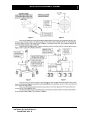
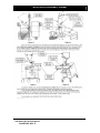
Cart Assembly...................................................................................................................................................... 38
Netlink Carts....................................................................................................................................................... 38
—
Assembly Instructions for the Netlink Tower Computer Cart 585-G2CADY (with video) and 585G2CAD0 (without video).................................................................................................................................... 39
—
Assembly Instructions for the Netlink Notebook Computer Roll Stand Cart (585-G2NTBK) ............... 45
Modular Anthro Carts......................................................................................................................................... 49
—
Bottom shelf ............................................................................................................................................ 49
—
Second Shelf............................................................................................................................................ 49
—
Third Shelf............................................................................................................................................... 50
—
Top Shelf (Selected models only) ........................................................................................................... 50
Types of computer ............................................................................................................................................... 51
Installation (Deskop and Tower computers)....................................................................................................... 51
Installation (Notebook computers) ..................................................................................................................... 52
Installation (MPC All-In-One computers) .......................................................................................................... 52
Monitor................................................................................................................................................................. 53
Mouse.................................................................................................................................................................... 53
Security Block ...................................................................................................................................................... 53
Printer................................................................................................................................................................... 53
External Storage Device(s).................................................................................................................................. 54
Installation verification ....................................................................................................................................... 54
OPTIONAL BOARDS INSTALLATION...................................................................................................... 56
Network card installation for Windows systems............................................................................................... 56
Installing the Network card ................................................................................................................................ 56
Network Driver Setup......................................................................................................................................... 57
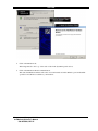
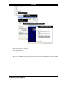
Configuring the Network Card for Windows 2000 ............................................................................................ 58
Headbox Installation ........................................................................................................................................... 60
Printer (optional) ................................................................................................................................................. 60
Mouse Installation ............................................................................................................................................... 61
Monitor Installation ............................................................................................................................................ 61
Photic Stimulator................................................................................................................................................. 61
Final System Assembly........................................................................................................................................ 62
DATA ACQUISITION MODULES AND CIRCUIT BOARDS ..................................................................... 64
Netlink and Netlink ICU Cable Connections .................................................................................................... 64
Circuit Boards in Netlink and Netlink ICU....................................................................................................... 65
Circuit Boards in computer ................................................................................................................................ 65
Ethernet interface board...................................................................................................................................... 65
ATI Radeon Video PCB (with Digital Video option)......................................................................................... 65
Optibase™ Digital Video Encoder PCB (with Digital Video option) ................................................................ 65
Digital I/O........................................................................................................................................................... 65
Reseating circuit boards...................................................................................................................................... 66
CARE AND MAINTENANCE...................................................................................................................... 68
Preventive maintenance checklists ..................................................................................................................... 68
Tools ................................................................................................................................................................... 68
Preliminary system inspection ............................................................................................................................ 68
Basic system functionality check........................................................................................................................ 68
Clean system components................................................................................................................................... 69
Optimize system ................................................................................................................................................. 69
Final system verification..................................................................................................................................... 69
TEST PROCEDURES AND DIAGNOSTICS.............................................................................................. 70
Collection test....................................................................................................................................................... 70
Printer test............................................................................................................................................................ 70
Netlink and Netlink ICU Diagnostics................................................................................................................. 70
Customer Features .............................................................................................................................................. 70
Features............................................................................................................................................................... 71
Installation files .................................................................................................................................................. 71
Bio-logic Software.............................................................................................................................................. 71
Other Software.................................................................................................................................................... 71
Impacts on Installation Software ........................................................................................................................ 71
Netlink Diagnostics Setup Screen....................................................................................................................... 72
Netlink Diagnostics Results Channel Summary Screen ..................................................................................... 73
Netlink Diagnostics Connection Warning Screen .............................................................................................. 74
Netlink Diagnostics Test in Progress Warning Screen ....................................................................................... 75
Netlink Diagnostics Impedance Adapter Reminder Screen................................................................................ 76
Impedance Circuit Test....................................................................................................................................... 77
UTILITIES ................................................................................................................................................... 78
Using the Tools utilities in Windows 2000 ......................................................................................................... 78
To launch the Tools Utility................................................................................................................................. 79
To check the disk drive for errors....................................................................................................................... 80
To backup a disk drive........................................................................................................................................ 82
To defragment a disk drive ................................................................................................................................. 84
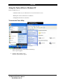
Using the Tools utilities in Windows XP............................................................................................................ 87
To launch the Tools Utility................................................................................................................................. 87
To check the disk drive for errors....................................................................................................................... 88
To defragment a disk drive ................................................................................................................................. 88
To backup a disk drive........................................................................................................................................ 89
Other Wizard programs ..................................................................................................................................... 90
Windows 2000 “Wizards” .................................................................................................................................. 90
Windows XP “Wizard”....................................................................................................................................... 92
P&TI UTILITIES .......................................................................................................................................... 94
How to launch the P&TI Utilities program....................................................................................................... 94
How to use the P&TI Utilities program............................................................................................................. 94
To backup databases:.......................................................................................................................................... 95
To repair databases: ............................................................................................................................................ 98
To restore databases:......................................................................................................................................... 101
To rebuild databases: ........................................................................................................................................ 103
To handle advanced options: ............................................................................................................................ 106
—
Launching the P&TI Utilities Options dialog box................................................................................. 107
—
Using the P&TI Utilities Options dialog box ........................................................................................ 108
To view and print details: ................................................................................................................................. 110
To print program messages:.............................................................................................................................. 110
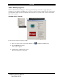
THE EVENT VIEWER UTILITY ................................................................................................................ 111
Windows 2000 Event Viewer: Overview ......................................................................................................... 111
Using Event Viewer ........................................................................................................................................... 112
To view more details about an event ................................................................................................................ 113
To search for specific types of events............................................................................................................... 115
To clear an event log......................................................................................................................................... 120
—Overwriting events ........................................................................................................................................ 122
—Increasing the maximum size of a log ........................................................................................................... 124
To archive an event log..................................................................................................................................... 126
To open an archived event log.......................................................................................................................... 129
Windows XP: Event Viewer: Overview........................................................................................................... 131
Events ................................................................................................................................................................. 132
Using Event Viewer ........................................................................................................................................... 133
To view more details about an event ................................................................................................................ 135
To search for specific events ............................................................................................................................ 136
To change the event log size............................................................................................................................. 139
CALIBRATION.......................................................................................................................................... 142
Introduction ....................................................................................................................................................... 142
Internal Amplifier Calibration......................................................................................................................... 142
Display Calibration ........................................................................................................................................... 143
Pulse Oximeter Calibration .............................................................................................................................. 143
TROUBLESHOOTING.............................................................................................................................. 144
Power pollutants ............................................................................................................................................... 144
Blackouts and brownouts.................................................................................................................................. 144
Voltage transients ............................................................................................................................................. 144
Electrical noise ................................................................................................................................................. 144
Equipment malfunctions................................................................................................................................... 144
Troubleshooting Table...................................................................................................................................... 146
TO FIND CUSTOMER SUPPORT............................................................................................................ 148
CONNECTOR PIN ASSIGNMENTS......................................................................................................... 150
Netlink and Netlink ICU connector pin assignments ..................................................................................... 150
Photic Strobe (Sync) cable ................................................................................................................................ 151
Ethernet Headbox cable.................................................................................................................................... 152
INDEX ....................................................................................................................................................... 154
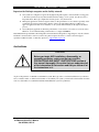
PRECAUTIONS AND SAFETY INSTRUCTIONS
Precautions and safety instructions
IMPORTANT
Only qualified personnel should use this device.
Please read this section and the Ceegraph or
Sleepscan Operator's manual before installing any
of the hardware. Keep this section as a reference
when you operate, transport, store, or re-install the
system.
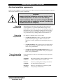
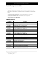
Equipment identification labels and markings
Classification
Warning labels and
symbols
The International Electrotechnical Commission classifies electro-medical
equipment according to its power source (external or internal) and the
degree of protection it provides against shock. The Netlink and Netlink
ICU is Class II, Type B and BF. This means it qualifies as externally
powered equipment that can protect a patient from electrical shock if
electrical parts (such as electrodes) have been applied to the patient.
Standard, internationally recognized symbols can avoid language
differences and provide instant comprehension of warnings and cautions
in a restricted space. These symbols appear on all Netlink and Netlink
ICU equipment or in Netlink documentation:
WARNING
Extreme danger. Injury or death is
possible. Consult accompanying
documents
TYPE BF EQUIPMENT
Patient applied parts (electrodes)
TYPE B EQUIPMENT
Other Patient parts
Sleepscan and Ceegraph Netlink
and Netlink ICU Service Manual
590-NETSM1, REV.E
1
PRECAUTIONS AND SAFETY INSTRUCTIONS
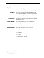
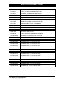
Electrical requirements
Use these requirements to avoid noise interference while recording electrical activity from patients and to make sure
of a consistent electrical environment for the computer system.
Isolated or non-isolated
power
15 or 20 amps
BTU offset
Magnetic field
Room shielding
Fluorescent lights
Although this system functions with non-isolated power, Natus
Medical Incorporated recommends an isolated power source for
maximum efficiency and safety.
Although 15 amps is acceptable in smaller systems, Natus
Medical Incorporated prefers 20 amp service any time the system
in use supports a large number of features.
A Natus Medical Incorporated computer system releases a
maximum of 2000 BTU per hour.
A Natus Medical Incorporated computer system operates without
any interference in a magnetic field of 0.05 Gauss.
Natus Medical Incorporated recommends room shielding but
does not require it. Users may use shielding if the room is close
to equipment that generates electrical "noise." Shielding is an
important safety precaution wherever noise is a potential
problem.
Natus Medical Incorporated recommends incandescent lights, but
the system can operate in a room with fluorescent lights.
Note: Dimmer switches can produce noise interference
unless the switch is set to full ON.
Thickness of the conduit
Sleepscan and Ceegraph Netlink
and Netlink ICU Service Manual
590-NETSM1, REV.E
Thickness for the conduit and for all electrical installations must
meet the National Electrical Code and applicable local codes.
2
PRECAUTIONS AND SAFETY INSTRUCTIONS
Electrical installation requirements
Install all system equipment at a properly grounded site. This section presents detailed information about how to
make sure the installation site meets requirements.
WARNING
Improper electrical installation can cause electric shock
to either the patient or the user. It can also damage
system equipment. Make sure patient electrodes DO NOT
make contact with any conductive material (including the
outside chassis of the computer).
Grounding
requirements
The installation site must have a grounding wire that connects the
system equipment to a grounded terminal (Earth). The grounded
terminal must connect to the steel skeleton of the building or under the
main reinforcing steel. Any multiple grounding wires must ground at
the same point. (One point grounding.) The shield room or bed must
also ground at the same grounding terminal as the installation site.
Power plug
requirements
Use only these configurations for the power plug:
Types of grounding
for hospital facilities
•
A 3-pin power plug: This requires a 3-pin wall socket with a
properly installed grounding pole. Make sure that the wall
receptacle is correctly grounded before inserting the 3-pin power
plug.
•
A 2-pin/3-pin adapter: This connects 3-pin power supply plugs to
a 2-pin wall socket. The grounding terminal on the adapter must
secure to the ground terminal.
•
A 2-pin power plug with a grounding terminal: This is for a 2pin wall socket: The grounding terminal on this power plug must
secure to the ground terminal
Use this information to make sure the installation site has appropriate
grounding:
Grounding
resistance:
The ground resistance of the grounding poles for the
medical equipment must be 10 ohms or less.
Protective
grounding:
Protective grounding must let leakage current flow
into the ground for patient safety.
Functional
grounding:
This type of grounding is not required for patient
safety. It helps eliminate hums.
Sleepscan and Ceegraph Netlink
and Netlink ICU Service Manual
590-NETSM1, REV.E
3
PRECAUTIONS AND SAFETY INSTRUCTIONS
Environmental specifications
Temperature
Operating: 15 to 40º C (59 to 104º F)
Storage: -20 to 70º C (-68 to 158º F)
Humidity
Operating: 15% to 95% at 40º C (104º F) non-condensing
Storage: Maximum 90% at 65º C (149º F)
Note: These are maximums and do not reflect typical or
recommended operating or storage environments.
Condensation
Flammability
EMC specifications
Recovery time after condensation to operational specification:
24 hours
UL94V-O
CISPR 11 B Conducted and CISPR 11A Radiated Emmisions
EN 61000-4-3 Radiated Susceptibility Test
EN 61000-4-4 Transient Susceptibility Test
EN 61000-4-5 Surge Susceptibility Test
EN 61000-4-6 Conducted Immunity Test
EN 61000-4-8 Magnetic Fields Test
EN 61000-4-11 Voltage Fluctuations Test
EN 61000-3-2 and EN 61000-3-3 Dips and Flicker Test
RS 101 Magnetic Immunity and RE 101 Magnetic Emmissions Test
Installation precautions
Use these precautions when installing or re-installing this system and equipment:
Environmental
conditions
• Select a room with properly grounded power sources. Reliable
grounding requires hospital-grade receptacles and power cord.
• Neither use nor store this system near storage locations for chemicals
or where gas leaks may occur.
• Avoid moisture or contact with water, extreme atmospheric pressure,
excessive humidity and temperatures, poorly ventilated areas, saline,
or sulphuric air.
• Make sure the installation site maintains a relative humidity between
15% and 95% (without condensation).
• Make sure the installation site meets all the requirements in the
Environmental Specifications section of this document (turn to that
section for more information).
• Although there are no known susceptibilities to electromagnetic
phenomena, there is always a possibility that electromagnetic
interference may affect system operation.
Sleepscan and Ceegraph Netlink
and Netlink ICU Service Manual
590-NETSM1, REV.E
4
PRECAUTIONS AND SAFETY INSTRUCTIONS
Room Topography
• Place all equipment on an even, level surface. Avoid the possibility of
mechanical shock or vibration during setup, system operation, or
system relocation.
• Make sure that the iso-transformer and all portable multiple socket
outlets are off the floor and in a dry location
WARNING
Only use the Power Supply Model Number
520-PS5V5A with the Netlink and Netlink ICU
amplifier.
System Hookups
• The Netlink and Netlink ICU headboxes are to be used only with their
associated power supplies, which are certified medical grade.
• System computer must plug into an approved isolation transformer
unless the computer is using an approved medical grade power
supply.
• Verify that the maximum load for any multiple portable socket-outlet
is less than 750 VA.
• Use the multiple socket-outlets to power only equipment that is a part
of the Netlink and Netlink ICU systems. (Additional equipment may
increase leakage and exceed the safety limit for connecting a patient.)
• Connect multiple pieces of equipment only after verifying that the
sum of all leakage currents is less than the safety limit for connecting
a patient.
• Connect no non-medical electrical equipment directly to a wall outlet
if the Netlink or Netlink ICU system is using a multiple portable
socket-outlet with a separating iso-transformer. (Additional equipment
may increase leakage and exceed the safety limit for connecting a
patient.)
• Connect no equipment with potential electromagnetic or other types
of interference. This could cause incorrect operation of the equipment
• Verify that the equipment connects to a power line source with the
following frequency, voltage, and current capacity.
Frequency:
Voltage:
Current Capacity:
Sleepscan and Ceegraph Netlink
and Netlink ICU Service Manual
590-NETSM1, REV.E
5
50 / 60 Hz
100 - 240 VAC
0.75-0.35 A
PRECAUTIONS AND SAFETY INSTRUCTIONS
Installation verification
To make sure that all system equipment is installed correctly before use:
—Verify that all equipment and cables are undamaged and in perfect working condition.
—Verify that all equipment and cables are connected according to the instructions in this manual.
—Verify that no unauthorized equipment is connected to the system.
—Verify that the equipment is properly grounded.
—Verify that all circuitry with a direct connection to the patient has been checked twice.
—Verify that all system or equipment batteries show the correct voltage and are in perfect working condition.
Precautions during system operation
CAUTION
This equipment is not protected from a cardiac
defibrillator discharge. Using a defibrillator while a
patient is connected to the system equipment may
permanently damage the equipment.
When using a defibrillator, either protect the equipment against defibrillator discharge or remove all patient cables,
transducers, or both to avoid system damage. See Caution above.
WARNING
Never turn power on or off with a patient connected
to the system.
1.
Follow all safety procedures; give careful and constant attention to the patient and system equipment.
2.
The Netlink/Netlink ICU does not provide protection against patient burns when used with electro-surgical
equipment. Follow hospital procedures to verify that all electrodes are properly applied in order to prevent
patient burns while using electro-surgical equipment.
3.
Turn system power on BEFORE you attach electrodes to the patient. Remove the electrodes from the patient
BEFORE you turn the system power off. This avoids shock hazards from power surges.
4.
Caution should be taken when simultaneously connecting Netlink/Netlink ICU and other patient-connected
equipment, to insure that hazards to the patient are not introduced through incorrect or inappropriate hookups.
5.
Attach electrodes to the patient and the system hardware so that the electrode cables can neither entangle nor
strangle the patient.
Sleepscan and Ceegraph Netlink
and Netlink ICU Service Manual
590-NETSM1, REV.E
6
PRECAUTIONS AND SAFETY INSTRUCTIONS
6.
Avoid direct contact between the patient and system equipment at all times.
7.
Do not add other equipment that is not protected against ingress of liquids.
8.
This equipment is not suitable for use in areas of flammable or anesthetic mixture.
Electrostatic Discharge (ESD) precautions
WARNING
Do not remove PC boards from their protective bags
or open your computer until you have read the
information below. Please follow the instructions
provided to avoid damaging the electronic
components of your system.
WHAT YOU MUST DO
Enclosed in your shipment is a package that contains a disposable wrist strap. The instructions for use appear on the
package. The black end of the strap wraps and adheres around the wrist. The adhesive is hypo-allergenic. The
adhesive-backed copper foil at the other end adheres to any convenient electrical ground. A convenient location is
the (non-painted) metal chassis of the computer. You must, however, leave the computer plugged into the isolation
transformer in order to provide a ground path. Be sure the switch on the Isolation Transformer is OFF. (DO NOT
turn the power on while you are strapped to the equipment!) Other convenient grounds are available at visible
conduits and water pipes (items cannot be painted). Once you are grounded via the disposable strap, you may safely
touch exposed electronics and PC boards. If you must lay a PC board down, lay it on the computer chassis or use
the protective bag.
ELECTROSTATIC DISCHARGE (ESD)
Everyone is aware of the shock that sometimes occurs when they touch a door knob. This shock is the discharge of
an electrostatic charge on your body. A static charge happens when two separate surfaces have too many or too few
electrons. One surface loses electrons to the other. The types of materials involved and the speed and duration of
motion between them determine the charge level. The list that follows shows common actions that generate a static
charge and the typical electrostatic voltages that your body can acquire (depending on humidity).
Walking across carpet:
1,500 volts – 35,000
volts
Walking across vinyl floor:
250 volts – 12,000 volts
Picking up poly bag:
1,200 volts – 20,000
volts
Relatively low levels of static electricity can destroy or degrade certain electronic components. Levels as low as 100
volts can seriously affect the performance of your equipment; from degraded performance to total system failure.
Some component degradation may result in total failure when that component must operate at or near its rated limit.
Consequently, safe practice demands that you protect the devices at all times from static charge and voltage fields.
Sleepscan and Ceegraph Netlink
and Netlink ICU Service Manual
590-NETSM1, REV.E
7
PRECAUTIONS AND SAFETY INSTRUCTIONS
Follow these ESD guidelines to ground the system equipment properly. Make sure you ground all system equipment
before you start any user, maintenance, or calibration procedure.
1.
Put on a grounded wrist strap before touching anything inside the computer.
NOTE: Natus Medical Incorporated packages a disposable, hypoallergenic, adhesive wrist
strap with some pieces of equipment. Follow instructions on the package to make sure
of proper grounding at all times when working on the equipment. A convenient
electrical ground is the non-painted metal chassis of the computer. Other convenient
grounds are non-painted water pipes and conduits.
2.
Make sure all equipment is turned OFF.
3.
Make sure the wrist strap is grounded to earth ground.
Once the system equipment is OFF and properly grounded, it is safe to touch the system PC boards and
components. If you must remove a PC board and lay it down, place it on the grounded computer chassis or
in the ESD protective bag.
The quality of your equipment depends a great deal on the reliability of the electronics. We make every attempt at
Bio-logic to handle the equipment and parts in an ESD safe environment. By continuing that practice you can avoid
ESD failures and degradation in your equipment. If you would like additional information on ESD and its effects,
make contact with the Customer Support Department.
Maintenance
The Natus Medical Incorporated Netlink and Netlink ICU require professional maintenance and repair service.
Never attempt to alter, modify, or repair this equipment alone. If the Netlink or Netlink ICU is not functioning
properly, mark all defective parts clearly to prevent accidental use before the appropriate repairs can be made. When
using a defibrillator, either protect the equipment against defibrillator discharge or remove all patient cables and/or
transducers to avoid system damage.
Sleepscan and Ceegraph Netlink
and Netlink ICU Service Manual
590-NETSM1, REV.E
8
ABOUT THIS MANUAL
ABOUT THIS MANUAL
This manual contains information about the maintenance of the Bio-logic System Corp. Netlink or Netlink ICU™
Amplifier Module and associated system components for the Ceegraph™ System, Sleepscan™ System, and their
associated hardware and software. It focuses most on the service and maintenance of hardware components and
contains assembly, disassembly, repair, installation, and troubleshooting procedures. General information about the
computer and its peripherals (such as the keyboard, monitor, disk drives, or motherboard) appears in third-party
(non-Bio-logic) service manuals. For information about how to use the Ceegraph System or the Sleepscan System,
please see their respective User’s Manual.
Sleepscan and Ceegraph Netlink
and Netlink ICU Service Manual
590-NETSM1, REV.E
9
ABOUT THIS MANUAL
Notes
Use this page for your own notes.
Sleepscan and Ceegraph Netlink
and Netlink ICU Service Manual
590-NETSM1, REV.E
10
SYSTEM OVERVIEW
System Overview
This section introduces the Netlink and Netlink ICU system. It contains basic information about the system, its
components, and its theory of operation.
Operational Overview
The Bio-logic Systems Corporation® Netlink™ and Netlink ICU system is a paperlesss, computer-based device that
collects and analyzes EEG (Ceegraph) and Sleep activity (Sleepscan). The Netlink’s software program works with
customized hardware components to give you a powerful, flexible EEG and Sleep collection and analysis system.
During collection, the software displays incoming data signals as waveforms on the computer screen (monitor). At
the same time, it records these signals to a data file on the computer’s hard disk (or other selected storage device).
After data collection, users can read data from the disk and display or print any part of the data file on the screen.
Sleepscan and Ceegraph Netlink
and Netlink ICU Service Manual
590-NETSM1, REV.E
11
SYSTEM OVERVIEW
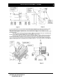
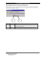
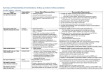
Theory of Operation
Block Diagram of the Netlink™ or Netlink ICU Amplifier
Sleepscan and Ceegraph Netlink
and Netlink ICU Service Manual
590-NETSM1, REV. E
12
SYSTEM OVERVIEW
Data Collection
Amplification, filtering, and Analog-to-digital conversion circuitry for the system reside in the Netlink or Netlink
ICU amplifier module (headbox). The illustration shows a block diagram of this device. During data collection,
analog EEG signals travel from electrodes on the patient to the system headbox.. Hardware in the headbox
amplifies, filters, and converts analog signals into digital values and then sends those values to the computer. There,
the computer stores them in its memory. Typically, the system displays the data on the computer’s monitor during
the collection process and then saves that data to a disk or other storage device for storage after analysis.
Data Analysis
During data analysis, the program retains the digitized patient data in the system computer hardware. This lets the
Ceegraph or Sleepscan program perform data analysis before the system saves the data to a storage disk.
Sleepscan and Ceegraph Netlink
and Netlink ICU Service Manual
590-NETSM1, REV. E
13
SYSTEM OVERVIEW
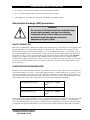
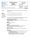
Hardware
NETLINK™ Amplifier Box
Sleepscan and Ceegraph Netlink
and Netlink ICU Service Manual
590-NETSM1, REV. E
14
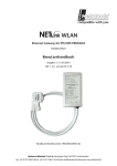
SYSTEM OVERVIEW
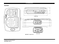
Hardware
Netlink ICU Amplifier Box
Sleepscan and Ceegraph Netlink
and Netlink ICU Service Manual
590-NETSM1, REV. E
15
SYSTEM OVERVIEW
Sleepscan and Ceegraph Netlink
and Netlink ICU Service Manual
590-NETSM1, REV. E
16
SYSTEM OVERVIEW
Sleepscan and Ceegraph Netlink
and Netlink ICU Service Manual
590-NETSM1, REV. E
17
SYSTEM OVERVIEW
Hardware components for this system may vary to meet specific requirements. The information in this section
describes the main components of the system. Some of these components are optional.
Amplifier module
See the illustrations on pages 14 and 15. The amplifier module
(headbox) has input jacks for patient electrodes. It also contains the
circuit boards necessary for amplifying, filtering, and analog-to-digital
conversion of low-level EEG signals.
Computer
This software requires a Pentium III or Pentium IV, IBM-compatible
system with a keyboard, 12 function keys, SVGA monitor, and internal
disk drive(s). Typical disk drives include a 1.44MB floppy disk drive, a
CD-ROM Drive, and a high capacity hard drive. Removable mass
storage options include CD+R/W drives and DVD drives. This system
also requires at least 512 MB RAM and Serial and Parallel I/O ports.
A/D Converter
All circuitry for converting analog signals to digital signals is inside the
Amplifier module (headbox).
Printer (optional)
This optional device lets users print copies of program screens or
reports. This software is compatible with most black and white or color
inkjet or laser printers.
Mouse
Safety Standards
The mouse is the primary input and control device for this software. It
also serves as an alternative to the computer’s keyboard.
This system complies with these electrical safety standards:
•
IEC 60601-1
•
IEC60601-1-1
•
IEC 60601-2-26
•
UL 60601-1
•
CAN/CSA C22.2 No. 601-1-M90
Sleepscan and Ceegraph Netlink
and Netlink ICU Service Manual
590-NETSM1, REV. E
18
SYSTEM OVERVIEW
Structure and Organization
This section discusses three important and fundamental aspects of the structure and organization of an operating
system: disk drives, files, and disk directories.
Drives
Most computers have disk drives that function as input or output devices. Users can move information (files) to
memory from media on a disk drive or from memory to media on a disk drive for permanent storage. The names for
drives on a computer follow a specific convention (usually consecutive letters of the alphabet).
Many computer systems have a floppy disk drive (Drive A☺. This is a 3.5” 1.44 MB disk drive. Systems also
contain at least one internal hard drive (Drive C☺. Users can partition this drive into several depending on its size.
Systems can support more than one internal hard drive. Users name partitioned drive segments, additional hard
drives, or both according to sequential alphabetical order.
Other types of drives continue the alphabetical naming convention. For example, a system with a floppy drive, a
hard drive, a CD-ROM Drive, a PCMCIA drive, and a DVD Drive might name the drives thus:
Floppy = A:
Hard drive = C:
CD-ROM drive = D:
PCMCIA drive = E
DVD drive = F
Other disk drives, including network drives, also continue to use the alphabetical naming convention depending on
the number of physical devices attached to the system.
Files
The operating system lets you create, analyze, and manipulate information by storing data in “files.” Files are the
basic unit of organization and can contain either program code or information (data). Files reside on storage media
or “disks” and have names that are unique to that disk. (That is, different files cannot be stored on the same disk
under the same file name). Although two different files can be stored under the same name on different disks, it is a
good idea to have unique file names for every file in your entire library. The file name extension designates the type
of file. This extension is usually three characters long and follows the primary file name after a “period.”
The table below lists valid and invalid file name characters.
Valid Characters:
Invalid Characters:
A-Z 0-9 $ & # % ( ) @ ^ { } ~ !
_ (underline) - (dash or hyphen) ` (open single quotation)
’ (apostrophe or closed single quotation)
?
.
,
; :
=
* /
\ +
“
Some applications programs are more restrictive with regard to the valid character set. Some allow only eightcharacters file names. Some create file names automatically. Most applications programs supply their own
extension. For example, when specifying a data file in the Ceegraph program, you would not specify the file name
extension. The program looks only to the primary file name. The Ceegraph program automatically appends the
appropriate extension to all data file names.
Sleepscan and Ceegraph Netlink
and Netlink ICU Service Manual
590-NETSM1, REV. E
19
SYSTEM OVERVIEW
Examples of file name extensions:
.EEG
.PAT
.EAD
.MRK
.OIT
.SPK
.MPG
Disk Directories or Folders
Disks with large storage capacities can contain a large number of files. The situation could be very confusing if you
were unable to organize them within disk directories (folders) and subdirectories. Directories (or folders) serve as
partitions for the storage of program and data files. With a directory structure, you can organize the files on a disk by
type, application, class, or however you like. Further, you can organize the files in a directory within smaller
subdirectories.
You can create a “branching structure” for your storage device by nesting directories within directories. Such a
structure has different “levels.” The top level of a directory structure is the “root” directory and is a property of all
formatted disks, regardless of whether any directories have been created or not.
Think of directories and subdirectories as individual disks. If you list a directory listing from within a subdirectory,
only the files in that subdirectory appear in the list. The number of bytes listed as available, though, refers to the
space available on the entire disk, not just the space in the subdirectory or directory.
For comprehensive information about creating/removing directories, changing directories, accessing files that are
not on the current directory or default drive, or other operating system instructions, consult the appropriate operating
system manual.
System Application Software
Most companies send their customers new media (floppy disks or CD-ROM) that contain advances and
enhancements in their program. This allows your system to be updated without factory modification. Although your
system is based upon a personal computer, never access any other commercial programs while operating the
CEEGraph or Sleepscan program. Other programs may interfere with their functionality.
Software Versions and Models
The model number of Bio-logic software depends on the type of computer that you ordered. In other words, the
hardware of a Bio-logic system determines the model of software run on that system. In most cases, the user should
NOT try to run a model of software on a system that did not originally come with the system.
The software version number indicates the age of the software. Typically, a program that is being created for the
first time uses a whole version number such as 1.00. Each time the software is changed or updated a new version
number applies to the software. For example, if the original version number of a program is version 1.00, the next
update of the software might be numbered version 1.05.
Not all customers receive all versions of the software that a company creates. Many companies, including Biologic, have different “releases” of software. For example, many companies have an “Alpha” software release that
may go only to company employees for testing. After that release and any modifications that occur, a company may
Sleepscan and Ceegraph Netlink
and Netlink ICU Service Manual
590-NETSM1, REV. E
20
SYSTEM OVERVIEW
initiate a “Beta” release. In this release, selected customers receive the new program to test it for potential problems
(bugs). The customers use the software extensively and report any bugs they find. Then, the company repairs the
bugs and issues a “final” release for all of its customers. Each of these releases, the Alpha, Beta, and final release,
has a separate version number.Bugs, Crashes, and Error Handling
A ‘bug’ is an error in the program that causes the system to do something other than what it should do. Note that a
bug is only a bug if:
—The user has correctly entered the keystroke(s) needed to execute a function
and
—The system executes the function incorrectly.
Sometimes, a computer system may “lock up” (that is, get in a state where the system does nothing despite
keystroke or mouse input). This condition is a crash. Typically, rebooting the system will correct this type of
problem.
Bio-logic software lets you know when you have attempted to execute a function improperly or when the system is
not ready to do what you have asked it to do. This is called error handling and it is usually accomplished by the
flashing of error messages on the computer monitor or by having the computer emit a warning sound (beep) when an
error has occurred. As an example, if you attempt to print to a printer that has its power turned off, the system lets
the user know there is a problem by flashing some type of “PRINTER NOT READY” error message.
Software
This software application program works on IBM-compatible microcomputers with the Windows 98™, Windows
2000™, or Windows XP™ Operating System .
It uses the operating system as the underlying program that connects and controls the various components of the
microcomputer system. Users can enter Windows 98/2000/XP commands to perform basic system functions (such
as loading word processors or database programs). Users can also operate Windows software to copy data from disk
to disk, to print data to an output device, or to run system maintenance programs (such as Scandisk and Defrag). For
information about Windows 98/2000/XP functions, refer to Windows On-Line help.
This software application is currently available on CD-ROM. In addition to supplying software for analyzing and
collecting patient data, Natus Medical Incorporated Also suppplies the entire Windows software library on CDROM.
Sleepscan and Ceegraph Netlink
and Netlink ICU Service Manual
590-NETSM1, REV. E
21
SYSTEM OVERVIEW
Notes
Use this page for your own notes.
Sleepscan and Ceegraph Netlink
and Netlink ICU Service Manual
590-NETSM1, REV. E
22
SYSTEM SPECIFICATIONS
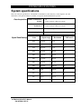
System specifications
This section lists the specifications of the Netlink or Netlink ICU system. Parts lists, circuit diagrams, and other
maintenance and repair information is available on request from Natus Medical Incorporated
Data Acquisition
Number of channels for
Netlink:
40
32 AC (isolated); 8 DC (non-isolated)
Number of channels for
Netlink ICU:
26
22 AC (isolated); 4 DC (non-isolated)
22 bit; one A/D per channel
A/D resolution:
256, 512, and 1024 per second
Sampling Rates:
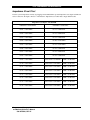
Signal Conditioning
Sleepscan and Ceegraph Netlink
and Netlink ICU Service Manual
590-NETSM1, REV. E
Gain
Input range
Resolution
LSB used
19.07
2.62 mV
4 µV
16
19.07
1.31 mV
2 µV
17
19.07
0.65 mV
1 µV
18
19.07
0.32 mV
0.5 µV
19
190.7
26.2 mV
0.4 µV
16
190.7
13.1 mV
0.2 µV
17
190.7
06.5 mV
0.1 µV
18
190.7
03.2 mV
0.05 µV
19
DC
10 V
152 µV
16
DC
5V
76 µV
17
DC
2.5 V
38 µV
18
DC
1.25 V
19 µV
19
23
SYSTEM SPECIFICATIONS
Signal
Conditioning
(continued)
AC Channels for
Netlink
32
24 referential inputs
8 bipolar or referential inputs
AC Channels for
Netlink ICU
22
18 referential inputs
4 bipolar or referential inputs
DC Channels for
Netlink
8 high level, non-isolated
Input Range: +/- 5V
Resolution: 38 µV at 18 bit
DC Channels for
Netlink ICU
4 high level, non-isolated
Input Range: +/- 5V
Resolution: 38 µV at 18 bit
Notch Filter
50/60 Hz Software digital filter
High Pass Filters
0.01 Hz or 0.1 Hz, software controlled with cutoff of 6dB per
octave, 1 pole
Low Pass Filters
570 Hz and 100 Hz 1 pole (in hardware)
12-18 dB per octave (2-3 pole) cutoff done digitally in
software
Input Impedance
>100 M ohm or more on isolated EEG channels
CMRR
>100 or better (typically, 110 dB on isolated EEG channels)
Noise Level
0.5 µV rms (0.1-100 Hz) on isolated EEG channels
Calibration Signal type
Sine wave, Square wave, DC step
Test signal
frequency
0.5 Hz thru 20 KHz
Test signal
amplitude
100m, 50m, 10m, 5m, 1m
500µ, 100µ, and 50µ Vpp
Impedance test Signal type
Sine wave; constant current source
Test signal
frequency
10 Hz to 20 Hz
Range
0-131 K Ohms at 2 µApp, 262 K Ohms at 1 µApp
Resolution
< 100 Ohms
Impedance
Pass/Fail
LED display per channel
Sleepscan and Ceegraph Netlink
and Netlink ICU Service Manual
590-NETSM1, REV. E
24
SYSTEM SPECIFICATIONS
Pentium III or higher
Computer Processor
Memory
512 MB RAM
Keyboard
Detachable 101-key; 12 Function keys
I/O
Parallel port; Serial ports
Mouse
For optional program control
Operating System
Windows 98/2000/XP™
1.44 MB
Storage Floppy disk
Hard Disk
40 GB or more
Other storage devices
CD ROM, DVD-RAM; CD+R/W
Display Options 17” screen Ultra-high Resolution 1600 x 1200 (optional)
20” screen Ultra-high Resolution 1600 x 1200 (optional)
Printers
Physical
Amplification
features
Laser; Color inkjet
Computer
Tower
17 cm W x 45 cm H x 43 cm D
Netlink
7” W x 2.5” H x 10” D
Internal calibration and impedance test
Built-in self test and system diagnostic capability
Automatic sensing of headbox connect/disconnect
All parameters operate under software control
Sleepscan and Ceegraph Netlink
and Netlink ICU Service Manual
590-NETSM1, REV. E
25
Desktop
45 cm W x 17 cm H x 43 cm D
SYSTEM SPECIFICATIONS
Options and
Accessories
Photic
Stimulator
Body
position
monitoring
Support arm
Frequency of flash
Light intensity
52 in. (1320.8 mm) total
Variable from 1Hz to 60 Hz
Adjustable via Intensity control
Accessory Receptacles
115VAC 50/60Hz, 750VA max.
(all loads combined)
Mains Input
115/230VAC 50/60Hz, 780VA
Replacement Fuses
Rating: 100-120V – T8AL 250 V (two
fuses required)
220-240V – T4AL 250 V (two fuses
required)
Generates an unique 4-bit code read on 4 data input pins of 4 analogto-digital converters
Input connector: 3-pin Plastics One™ connector
One pin indicates connection
Oximeter
Plugs into digital board
Reads data on serial port
EMI filtering for inputs and outputs
See the Oximeter section of this manual for details.
Pushbutton
controls
Start and stop collection; Start and stop impedance test pushbuttons
Power 200 Watts, 50/60 Hz, 120/240 Volts (Auto Switching)
Operating Temperature
STANDARDS
15-30º C
59-86º F
IEC 60601-1
IEC60601-1-1
IEC 60601-2-26
UL 60601-1
CAN/CSA C22.2 No. 601-1-M90
Sleepscan and Ceegraph Netlink
and Netlink ICU Service Manual
590-NETSM1, REV. E
26
SYSTEM SPECIFICATIONS
Oximeter
Oxygen saturation range
Pulse rate range
Accuracy SpO2
(±1 standard deviation)
0-100%
18 – 300 pulses per minute
70-100% ±2 digits for adults using a fingertip sensor
70-100% ±3 digits for neonates using infant or neonatal sensors
70-100% ±3 digits for adults using Flex or Reflectance sensors
70-100% ±4 digits using earclip sensors
Rate accuracy
Patient isolation
Dimensions
Weight
±3 %; ±1 digit
Greater than 12 megohm
34.5 x 46 x 9 mm
1.35” x 1.8” x 0.36”
12 g
For more information about the Oximeter printed circuit board, make contact with:
Nonin Medical, Inc.
2605 Fernbrook Lane North
Plymouth, MN 55447-4755
1-800-356-8874
Isolation Transformer
Isolation Transformer is used only when a Medical Grade Power Supply is not used. Refer to Isolation Transfomer
User’s and Service Manual 590-ISOXM1 for specifications and use.
Sleepscan and Ceegraph Netlink
and Netlink ICU Service Manual
590-NETSM1, REV. E
27
SYSTEM SPECIFICATIONS
Notes
Use this page for your own notes.
Sleepscan and Ceegraph Netlink
and Netlink ICU Service Manual
590-NETSM1, REV. E
28
INSTALLATION, DISASSEMBLY, ASSEMBLY
INSTALLATION, DISASSEMBLY, ASSEMBLY
Customization and configurations
Bio-logic computer systems have a custom configuration. This customization is not only in the software installed but
in the network configuration as well. In some cases these computers will have one network interface card (NIC) and
in other cases there will be two NIC’s. The customized settings are critical to the proper functioning of the system.
In a single NIC configuration, the card is used to communicate with other Bio-logic computer systems. In the dual
NIC configuration one card is used to communicate with other Bio-logic computer systems as in the single NIC
configuration and the other NIC is used to communicate with the amplifier. TCP/IP is the only protocol used by
Bio-logic computer systems. All NIC’s will have static IP addresses assigned to them and have no need for WINS,
DNS, or host file name resolution. The only other network components necessary are file and print sharing, and
client for Microsoft networks. On a dual NIC configuration the network card being used to communicate with the
amplifier must only have the protocol bound.
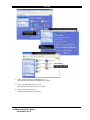
Three IP addressing ranges or subnets are used by Bio-logic equipment for communication.
For communication between computers the subnet used is 192.168.064.000.
For communication between computers and XL amplifiers is 207.227.127.000
♦ For communication with Netlink or Netlink ICU amplifiers are 192.168.072.000.
♦
♦
Only two addresses are used in each of the amplifier subnets.
♦
♦
The amplifier will always have an address of xxx.xxx.xxx.29.
The NIC used to communicate with the amplifier will always have an address of xxx.xxx.xxx.30.
On the subnet used for communication between computers, the number of addresses in use is determined by the
number of machines on the network with the collector computer addresses beginning with 192.168.64.01, the reader
computer addresses beginning at 192.168.64.101 and laptop addresses beginning at 192.168.64.201.
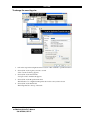
All Bio-logic computer workstations are configured with two partitions on a single physical disk. The extended
partition has one logical partition which is where all the data is stored. The DVD RAM drive is used for data
archiving. Each computer will have two network shares configured, the data partition and the DVD RAM drive.
These shares must be setup to allow all users full access. This will not affect the data security on the facility or Biologic LAN as Bio-logic computers should be on an isolated network. These shares are vital as the software makes
use of them. Bio-logic also makes several other less obvious modifications to the operating system. Each of these
modifications is designed to enhance the performance of the system and our software.
User accounts and privileges need to be considered when using Windows NT 4.0 and Windows 2000 Professional,
with the end user having a logon with administrative privileges on the local machine. This level of privileges is
needed to update the software as they become available and for some of the software features to function. Our
technicians configure the local administrator account with a password known only to Bio-logic personnel. An
account with local administrative privilege is a critical tool for our support personnel to use when supporting these
systems. For these reasons, it is vital that the password not be changed, except by a Bio-logic employee.
Sleepscan and Ceegraph Netlink
and Netlink ICU Service Manual
590-NETSM1, REV. E
29
INSTALLATION, DISASSEMBLY, ASSEMBLY
Important for Bio-logic computers on the facility network:
♦
♦
♦
Our systems are configured to ignore the daylight saving time updates. If network time is being given
to the client systems in any way that can affect the time settings on our systems. For this reason it is
important that no Bio-logic computer has its time given to it by the network.
Third party applications can have negative effects on the performance of our software especially on the
systems that are used for patient data collection. Due to the performance impact, non Bio-logic
approved applications must not be installed on our systems either manually or through an automated
process.
Just as third party applications affect the performance of our software so does the use of screen savers.
Therefore, we recommend turning off the monitor to comply with HIPPA.
Natus Medical Incorporated Has a knowledgeable and well-trained staff capable of supporting not only the software
but the PC’s and networks as well. If you have any questions please feel free to contact a customer support
specialist at (800) 323-8326, or email any questions to [email protected].
Instructions
WARNING
Before you begin ANY installation, disassembly, or
assembly procedure, make sure that you read the
PRECAUTIONS AND SAFETY INSTRUCTIONS section of
this manual thoroughly. Be certain that you understand all
of the information in that section and that you follow all of
the instructions in it.
As part of the purchase of a Netlink or Netlink ICU system, Bio-logic offers a one-time installation. If you decide to
move, re-install, return, or otherwise disassemble or reassemble your system, you must follow the instructions in this
section to disassemble or assemble the Netlink and Netlink ICU system for optimal use.
Sleepscan and Ceegraph Netlink
and Netlink ICU Service Manual
590-NETSM1, REV. E
30
INSTALLATION, DISASSEMBLY, ASSEMBLY
Disassembly for storage or return—general instructions
This section presents general instructions for disassembling your Netlink and Netlink ICU system. Specific
installation instructions—including assembly procedures—follow. For detailed disassembly procedures, reverse the
assembly steps. That is, start at the final step and follow them in reverse order; substitute “unscrew” for “screw,”
unplug” for “plug,” and so on.
Handle the system carefully during disassembly for storage or return If problems arise at any point, stop the process
immediately and make contact with Natus Medical Incorporated Customer Support at 1-800-303-0306. Follow these
general steps:
1.
Return all controls to their original positions.
2.
Turn off all system equipment.
3.
Remove all connecting cables carefully without using force.
4.
Follow designated hospital procedures to clean the equipment and its electrodes
5.
Store the equipment according to the environmental specifications in this document.
OR
6.
Repack the original carton with only the defective equipment; use the same packing material to make sure
the product is not damaged.
Note: Damaged material is not covered under First Year Warranty or Service Contracts.
Returning damaged material will result in an invoice for the full retail price of the
damaged part.
7.
Make sure a specific Reference Number is visible on the outside of the carton.
8.
Seal the carton and return to its original delivery address for pickup by UPS.
Note: When you package printers for storage or return, make sure that you remove ink or
toner cartridges.
WARNING
Never use equipment that has parts missing or equipment
that might contain loose parts inside of it (that is, inside an
enclosed portion of the equipment). If you suspect a piece
of equipment has missing or loose parts, make contact
with Bio-logic System Corp
Sleepscan and Ceegraph Netlink
and Netlink ICU Service Manual
590-NETSM1, REV. E
31
INSTALLATION, DISASSEMBLY, ASSEMBY
The return process normally takes ten (10) business days. If Bio-logic does not receive the defective item
within this time span, an invoice will be issued for the full retail price along with any applicable shipping
charges. These invoices will be issued regardless of First Year Warranty or Service Contract status.
Bio-logic will only issue UPS Call Tags once. If you miss all attempts by UPS to pick-up the replaced
product, you may return it to Bio-logic at your expense. These returns must be received at Bio-logic within
ten business days of your receipt of requested exchange product. Bio-logic also offers UPS ARS
(Automated Return Service) labels upon request.
If you have any questions or comments regarding this policy, or if anything unexpected occurs that affects
this procedure, please make contact with us at 800-323-8326, ext. 222.
Unpacking and Assembly
1.
Count the cartons. Verify that the entire shipment is there.
2.
Verify contents against packing slip.
The packing slip is in carton one.
3.
Unpack the boxes by system, one system at a time.
4.
Examine Installer Package in Box 1.
Networking information is in the Installer Package.
5.
Check for damaged equipment.
IF DAMAGE TO THE CONTENTS HAS OCCURRED
—Keep all damaged cartons and packing for investigation by the carrier.
—Make contact with Bio-logic to request a replacement system(s) and/or accessories and to notify
carrier.
6.
After assembly and testing, complete the Installation Report (F09.025) on each system.
7.
Review backorder lists and information from Natus Medical Incorporated Customer Support.
8.
Check all packing material to ensure that nothing is accidentally thrown away.
Sleepscan and Ceegraph Netlink
and Netlink ICU Service Manual
590-NETSM1, REV. E
32
INSTALLATION, DISASSEMBLY, ASSEMBY
Installer Package Documentation
The following documentation is in the Installer Package. The Installer Package is inside the Natus Medical
Incorporated Boxes.
—Installation & Inspection Form F09.002 – This form confirms a system inspection, system
functionality, and system verification. Installation personnel should complete it for each individual
system.
—Collection & Analysis Quick Guides – Included for Training and customer reference
—Security Block Information – This sheet defines the system security block.
—Supplies and Accessories Questionnaire
Optional Parts List
Part Number
Description
520-PS5V5A
Power Supply, 5V, 5A 100-240V input
520-PSMPC1
Medical Power Supply, 20V, 9A, 100-250V input
541-CORD12
HGPS CORD, 12 FT, 16/3 SJT, UL/CSA AP
541-ETH006
CABLE, ETHERNET, CAT5, 100MHZ, 6'
541-ETH010
CABLE, ETHERNET, CAT5, 100MHZ, 10'
541-ETH015
CABLE, ETHERNET, CAT5, 100MHZ, 15'
541-ETH025
CABLE, ETHERNET, CAT5, 100MHZ, 25'
541-ETH050
CABLE, ETHER, CAT5, STRAIGHT, 50'
541-ETH100
CABLE, ETHERNET, CAT5, 100MHZ, 100'
541-NETPHO
CABLE, SUB-ASSY, NETLINK PHOTIC STI
541-NETQC1-006
CABLE, NETLINK TO QUICK DISCONNECT, 6'
541-NETQC1-025
CABLE, NETLINK TO QUICK DISCONNECT, 25'
550-WRCLP1
CABLE ROUTING, 1.44 DIA TWIST-LOCK
575-CMSBBX
BRACKET-SLIDE, BOX MOUNT
575-CMSBMT
BRACKET-SLIDE, HOLDER
577-8000AA
FINGER CLIP SENSOR, NONIN 8000AA
577-BELT01
BELT,ADJUSTABLE,SNAP BCKL,2
577-POUCH6
POUCH,F/32CH QDH,DISPOSABLE, BLK W/
580-AIRPS3
CABLE, AIR PRESSURE TRANSDUCER W/RJ
Sleepscan and Ceegraph Netlink
and Netlink ICU Service Manual
590-NETSM1, REV. E
33
INSTALLATION, DISASSEMBLY, ASSEMBY
Part Number
Description
580-AIRPS5
CABLE, AIR PRES TO HYPERTRONICS FEM
580-AIRPS9
ASSEMBLY, AIR PRESSURE TRANSDUCER
580-AIRPSK
KIT,AIR PRESSOR SENSOR,SENSOR & ACC
580-CG2PG1
ASSEMBLY, CABLE/INTERFACE, FOR 580-
580-CG2PGR
ASSEMBLY, CEEGRAPH TO VISIPLEX PAGE
580-CG2TEL
INTERFACE ASSEMBLY, CEEGRAPH TO TEL
580-CG2TL2
PCB ASSY, DB-37 CIRCUIT, CEEGRAPH T
580-CGAUX1
CABLE,GAMMA AUX PAT INPUT,16CH,HOND
580-G2CGDC
NETLINK HEADBOX, NO OXI, W/DC
580-G2CGSS
NETLINK HEADBOX, W/OXI, W/DC
580-MOUSEP
MOUSEPAD W/BLCS LOGO
580-NELCBL
CABLE, NELLCOR OXIMETER TO CEEGRAPH
580-NELCBL-040
OXIMETER TO CEEGRAPH, 40FT, NELLCOR
580-NELCBL-070
OXIMETER TO CEEGRAPH, 70FT, NELLCOR
580-NETOX1-010
OXIMETER INTF, 3.5-3.5mm PLUG 10FT
580-NETOX1-025
OXIMETER INTF, 3.5-3.5mm PLUG 25FT
580-NETOX1-050
OXIMETER INTF, 3.5-3.5mm PLUG 50FT
580-NETOX1-075
OXIMETER INTF, 3.5-3.5mm PLUG 75FT
580-NETOX1-100
OXIMETER INTF, 3.5-3.5mm PLUG 100FT
580-NETOX1-125
OXIMETER INTF, 3.5-3.5mm PLUG 125FT
580-NETOX1-150
OXIMETER INTF, 3.5-3.5mm PLUG 150FT
580-NETOX1-175
OXIMETER INTF, 3.5-3.5mm PLUG 175FT
580-NETOX1-200
OXIMETER INTF, 3.5-3.5mm PLUG 200FT
580-NETOX2-010
OXIMETER INTF, 3.5mm-3/32 PLUG 10FT
580-NETOX2-025
OXIMETER INTF, 3.5mm-3/32 PLUG 25FT
580-NETOX2-050
OXIMETER INTF, 3.5mm-3/32 PLUG 50FT
580-NETOX2-075
OXIMETER INTF, 3.5mm-3/32 PLUG 75FT
580-NETOX2-100
OXIMETER INT, 3.5mm-3/32 PLUG 100FT
Sleepscan and Ceegraph Netlink
and Netlink ICU Service Manual
590-NETSM1, REV. E
34
INSTALLATION, DISASSEMBLY, ASSEMBY
Part Number
Description
580-NETOX2-125
OXIMETER INT, 3.5mm-3/32 PLUG 125FT
580-NETOX2-150
OXIMETER INT, 3.5mm-3/32 PLUG 150FT
580-NETOX2-175
OXIMETER INT, 3.5mm-3/32 PLUG 175FT
580-NETOX2-200
OXIMETER INT, 3.5mm-3/32 PLUG 200FT
580-NETOX3-010
OXIMETER INTF, 3.5mm PLUG-BNC 10FT
580-NETOX3-025
OXIMETER INTF, 3.5mm PLUG-BNC 25FT
580-NETOX3-050
OXIMETER INTF, 3.5mm PLUG-BNC 50FT
580-NETOX3-075
OXIMETER INTF, 3.5mm PLUG-BNC 75FT
580-NETOX3-100
OXIMETER INTF, 3.5mm PLUG-BNC 100FT
580-NETOX3-125
OXIMETER INTF, 3.5mm PLUG-BNC 125FT
580-NETOX3-150
OXIMETER INTF, 3.5mm PLUG-BNC 150FT
580-NETOX3-175
OXIMETER INTF, 3.5mm PLUG-BNC 175FT
580-NETOX3-200
OXIMETER INTF, 3.5mm PLUG-BNC 200FT
580-NETOX4-010
OXIMETER INTF, 3.5mm PLUG-DB9 10FT
580-NETOX4-025
OXIMETER INTF, 3.5mm PLUG-DB9 25FT
580-NETOX4-050
OXIMETER INTF, 3.5mm PLUG-DB9 50FT
580-NETOX4-075
OXIMETER INTF, 3.5mm PLUG-DB9 75FT
580-NETOX4-100
OXIMETER INTF, 3.5mm PLUG-DB9 100FT
580-NETOX4-125
OXIMETER INTF, 3.5mm PLUG-DB9 125FT
580-NETOX4-150
OXIMETER INTF, 3.5mm PLUG-DB9 150FT
580-NETOX4-175
OXIMETER INTF, 3.5mm PLUG-DB9 175FT
580-NETOX4-200
OXIMETER INTF, 3.5mm PLUG-DB9 200FT
580-NETOX5-010
OXIMETER INTF, 3.5mm-RCA PLUG 10FT
580-NETOX5-025
OXIMETER INTF, 3.5mm-RCA PLUG 25FT
580-NETOX5-050
OXIMETER INTF, 3.5mm-RCA PLUG 50FT
580-NETOX5-075
OXIMETER INTF, 3.5mm-RCA PLUG 75FT
580-NETOX5-100
OXIMETER INTF, 3.5mm-RCA PLUG 100FT
580-NETOX5-125
OXIMETER INTF, 3.5mm-RCA PLUG 125FT
580-NETOX5-150
OXIMETER INTF, 3.5mm-RCA PLUG 150FT
Sleepscan and Ceegraph Netlink
and Netlink ICU Service Manual
590-NETSM1, REV. E
35
INSTALLATION, DISASSEMBLY, ASSEMBY
Part Number
Description
580-NETOX5-175
OXIMETER INTF, 3.5mm-RCA PLUG 175FT
580-NETOX5-200
OXIMETER INTF, 3.5mm-RCA PLUG 200FT
580-NETOX6-006
(4) 3.5mm PHONE PLUG TO RJ45 6 FT.
580-NETOX6-012
(4) 3.5mm PHONE PLUG TO RJ45 12 FT.
580-NETOX7-100
CABLE, MASIMO OXIMETER TO NETLINK
580-NETPBT
PUSH BUTTON, EVENT (NETLINK)
580-NETPHO-002
CABLE, ASSEMBLY, 18
580-NETPHO-025
CABLE, ASSEMBLY, 25ft NETLINK PHOTI
580-NLICU1
NETLINK ICU HEADBOX, W/OXI, W/DC
580-NLICU2
NETLINK ICU HEADBOX, NO OXI, W/DC
580-QCBG2A
MODULE ASM, QUICK CONNECT, NETLINK
580-QDH32G
BOX,QUICK DISCONN.,32CH,PIVOTING CO
580-XFS751
TESTED, ASM XFMR SA 120V 750VA
580-XFS752
TESTED, ASM XFMR SA 240V 750VA
585-CAMMT2
POLE-CAMERA MTG, TELESCOPING FOR NE
585-CDREX7
CDRW, external, LTR-52246S black
585-CDRIN7
CDRW, Internal, LTR-52246S Black
585-CMB002
Battery; CPAQ P4
585-CPSY11
Power Supply for CPAQ P4 DT/TWR
585-CPSY12
Power Supply, HP Vectra VL420 Tower
585-DPRT03
HP DJ MODEL 960cxi PRINTER
585-ETHPR1
Intel Ether Pro/100 NIC Adapter
585-ETHPR2
Intel Ether Pro/1000 GB Adapter
585-ETHS03
Ethernet Switch, 8-Port GB Switch
585-FAN101-001
PENTIUM HEATSINC W/MOLEX AT PWR
585-FAN104
Fan, Proc. Fan/Heat Sinc
585-FLOP03
Disk Drive CPAQ EVO D510
585-G2CAD0
TELESCP ROLL STAND CART, CPU TWR,NO
585-G2CADY
TELESCP ROLL STAND CART, CPU TWR W/
Sleepscan and Ceegraph Netlink
and Netlink ICU Service Manual
590-NETSM1, REV. E
36
INSTALLATION, DISASSEMBLY, ASSEMBY
Part Number
Description
585-G2NTBK
TELESCP ROLL STAND CART, NOTEBOOK C
585-G2PHOT
ROLL STAND CART, PHOTIC LAMP & HEAD
585-G2WLMT
NETLINK HEADBOX WALL MOUNT, VERT ADJUSTABLE
585-HDI030
Hard Drive, 80 GB, Maxtor
585-HDI031
Hard Drive, 250GB, Maxtor
585-KBD007
Keyboard, COMPAQ P4 EVO D510
585-LFD212
DVD-RAM,9.4GB,Multi-D,Panasonic
585-LPRT05
Printer, Laser, Lexmark E323
585-MON010
20 flat w/spk. model VP201m black
585-MON011
17 NEC MultiSync LCD 1760V Black
585-MONO12
19 Viewsonic LCD Blk. Monitor
585-MOUS16
Mouse, 2-Button Scroll PS/2, Black
585-NETBPS
SENSOR, BODY POSITION FOR NETLINK
585-NETBPS-1
SENSOR, BODY POSITION FOR NETLINK
585-SW9571
DVD-RAM, 9.4GB, MULTI-D, PANASONIC
585-TLYCT0
TROLLEY-CEEGRAPH, W/OUT VIDEO
585-TLYCT1
TROLLEY-CEEGRAPH, W/VIDEO
590-G2CADY
ASSEM, CART 585-G2CADY & 585-G2CAD0
590-G2NTBK
ASSEM, CART 585-G2NTBK
590-G2PHOT
INSTALLATION FOR 585-G2PHOT CART
590-G2WLMT
INSTALL, WALL MOUNT FOR HEAD BOX
590-NETSM1
COVER INSERT, NETLINK SRV MANUAL
Sleepscan and Ceegraph Netlink
and Netlink ICU Service Manual
590-NETSM1, REV. E
37
INSTALLATION, DISASSEMBLY, ASSEMBY
Cart Assembly
Netlink Carts
Detailed Assembly directions on the Netlink carts appear in these documents:
Netlink and Netlink ICU Tower Computer Cart 585-G2CADY-Rev B (with and without video)
Netlink and Netlink ICU Notebook Computer Roll Stand Cart 590-G2NTBK-Rev B
We duplicate those documents here for your convenience.
Sleepscan and Ceegraph Netlink
and Netlink ICU Service Manual
590-NETSM1, REV. E
38
INSTALLATION, DISASSEMBLY, ASSEMBY
— Assembly Instructions for the Netlink Tower Computer Cart 585-G2CADY
(with video) and 585-G2CAD0 (without video)
Sleepscan and Ceegraph Netlink
and Netlink ICU Service Manual
590-NETSM1, REV. E
39
INSTALLATION, DISASSEMBLY, ASSEMBY
Sleepscan and Ceegraph Netlink
and Netlink ICU Service Manual
590-NETSM1, REV. E
40
INSTALLATION, DISASSEMBLY, ASSEMBY
Sleepscan and Ceegraph Netlink
and Netlink ICU Service Manual
590-NETSM1, REV. E
41
INSTALLATION, DISASSEMBLY, ASSEMBY
Sleepscan and Ceegraph Netlink
and Netlink ICU Service Manual
590-NETSM1, REV. E
42
INSTALLATION, DISASSEMBLY, ASSEMBY
Sleepscan and Ceegraph Netlink
and Netlink ICU Service Manual
590-NETSM1, REV. E
43
INSTALLATION, DISASSEMBLY, ASSEMBY
Sleepscan and Ceegraph Netlink
and Netlink ICU Service Manual
590-NETSM1, REV. E
44
INSTALLATION, DISASSEMBLY, ASSEMBY
— Assembly Instructions for the Netlink Notebook Computer Roll Stand Cart
(585-G2NTBK)
Sleepscan and Ceegraph Netlink
and Netlink ICU Service Manual
590-NETSM1, REV. E
45
INSTALLATION, DISASSEMBLY, ASSEMBY
Sleepscan and Ceegraph Netlink
and Netlink ICU Service Manual
590-NETSM1, REV. E
46
INSTALLATION, DISASSEMBLY, ASSEMBY
Sleepscan and Ceegraph Netlink
and Netlink ICU Service Manual
590-NETSM1, REV. E
47
INSTALLATION, DISASSEMBLY, ASSEMBY
Figure 12
The completed assembly should look like Figure 12.
Sleepscan and Ceegraph Netlink
and Netlink ICU Service Manual
590-NETSM1, REV. E
48
INSTALLATION, DISASSEMBLY, ASSEMBY
Modular Anthro Carts
This section applies only to systems with an Anthro cart. Depending on the model, some carts use three
shelves while others use four.
— Bottom shelf
Position the computer in the center of the bottom shelf.
— Second Shelf
To secure the isolation transformer to the second shelf, follow these steps:
1.
Align the holes in the base of the isolation transformer with the holes in the second shelf.
2.
Insert the first of four screws through the pre-drilled hole of the shelf and the base of the isolation
transformer.
3.
Hold the screw in place,
AND
4.
Thread a nut onto the protruding end of the screw.
5.
Tighten the nut securely.
6.
Repeat these steps to install the remaining screws and nuts.
7.
Verify the isolation transformer is securely in place.
Sleepscan and Ceegraph Netlink
and Netlink ICU Service Manual
590-NETSM1, REV. E
49
INSTALLATION, DISASSEMBLY, ASSEMBY
— Third Shelf
To position the monitor and the keyboard on the third shelf, follow these steps:
1.
Place the monitor (15", 17", 20") on the center of the third shelf.
2.
Position the keyboard on the keyboard pull-out tray at the bottom of the third shelf.
3.
Make one loop of the monitor cable
AND
4.
Position that cable behind the keyboard.
— Top Shelf (Selected models only)
To position the printer and optional buffer on the top shelf, follow these steps:
1.
Extend the printer stand to accommodate the width of the printer.
2.
Position the printer on top of the printer stand.
3.
Position the buffer next to the printer on the shelf.
Sleepscan and Ceegraph Netlink
and Netlink ICU Service Manual
590-NETSM1, REV. E
50
INSTALLATION, DISASSEMBLY, ASSEMBY
Types of computer
Bio-logic supplies its systems on several different types of computers. Not all models have the same components.
All peripheral devices, however, have labels that identify their connection port. Match these labels with those on the
computer. Because Bio-logic continuously improves the options available for its system, connection options may
vary.
Note: Always check the labels to help you as you assemble or disassemble the system.
Installation (Deskop and Tower computers)
The Netlink series ships as a unit. The computer and keyboard are separate. A Natus Medical Incorporated
representative usually performs initial installation procedures. If you decide to uninstall or move your system and
must install it again, follow these steps:
1.
Connect the keyboard cable to the back of the computer (if necessary).
2.
If a printer is provided:
—Connect the printer cable to the back of the computer at the connector labeled 'PRINTER' (if necessary).
—Connect the printer's power cable from the isolation transformer to the power connector on the printer/plotter
next to the printer cable connector.
3.
Connect the power cable from the main power supply to the isolation transformer.
4.
Connect the power cable from the computer to the isolation transformer.
5.
If a separate monitor is provided:
—Connect the monitor's cable to the DB15 connector labeled 'MONITOR' on the back of the computer.
—Plug the monitor's power cord into the isolation transformer.
6.
Connect one end of the ethernet cable to the connector under the computer icon on the Netlink or Netlink ICU
box.
7.
Connect the other end of the ethernet cable to the ethernet connector labeled ‘Netlink’ on the computer.
On many computers, this connector is on the back panel. Check your computer's documentation for its location.
8.
Turn the system power ON.
—Wait for the Power indicator to light on the Netlink or Netlink ICU unit.
—Wait for the Fault indicator to extinguish on the Netlink or Netlink ICU unit.
To uninstall the system, follow these steps in reverse order. Use "unplug" rather than plug and "disconnect from"
rather than "connect to."
Sleepscan and Ceegraph Netlink
and Netlink ICU Service Manual
590-NETSM1, REV. E
51
INSTALLATION, DISASSEMBLY, ASSEMBY
Installation (Notebook computers)
Installation procedures for laptop computers are very similar to those for desktop or tower computers. Differences
may include:
—Many notebook computers have a built-in “touchpad” rather than a mouse. If you plug a mouse into a
desktop computer, you usually connect it to the side of the laptop.
—Many notebook computers have a DVD or CD-ROM drive built into the system.
—Some notebook computers let you disengage the monitor lid by pressing buttons at the front, top, right and
left corners of the unit.
—To connect power:
1.
Plug the power cord into the side of the notebook.
2.
Plug the other end of the power cord into an isolation transformer to hospital-grade wall outlet .
Installation (MPC All-In-One computers)
Installation procedures for MPC computers are very similar to those for desktop or tower computers. Differences
may include:
1.
Plug the Medical Power Supply 520-PSMPC1 (Jerome Industries WSX820M) into the MPC computer.
2.
Plug the Hospital Grade power cord 541-CORD12 into the medical power supply.
3.
Plug the other end of the power cord into a hospital-grade wall outlet.
WARNING
Only use the Power Supply Model Number
520-PSMPC1 with the MPC All-In-One
computers.
Sleepscan and Ceegraph Netlink
and Netlink ICU Service Manual
590-NETSM1, REV. E
52
INSTALLATION, DISASSEMBLY, ASSEMBY
WARNING
Always perform a leakage current test and compare to
allowable standards BEFORE connecting the patient to
monitoring equipment
NEVER connect a multiple portable socket outlet to the
isolation transformer output receptacles. Additional cord
connected equipment may increase leakage currents and
present a hazard.
1.
Measure the leakage currents with all devices connected; make sure they are less than the allowable maximum
BEFORE connecting the diagnostic equipment to patient.
2.
Turn the switch on the back of the isolation transformer ON.
3.
Use the diagnostic equipment per the instructions.
Monitor
Monitor cables usually connect via a DB15 connector. One end of this cable is labeled "monitor" and connects to the
computer port that is labeled "monitor". Connect the power cord to the back of the monitor.
Note: For comprehensive information, see the manual for your monitor.
Mouse
The mouse attaches to the back of the computer with a female pin connector (labeled with a pictorial "mouse,” PS2,
or Serial Port 1).
Note: For comprehensive information, see the manual for your mouse.
Security Block
A security Block may be attached to the Parallel Port. If so, plug the printer cable into the Block.
Printer
If no security Block is present, attach the Printer cable to the Parallel Port (marked ‘Printer’). Attach the printer
power supply to the Isolation Transformer.
Sleepscan and Ceegraph Netlink
and Netlink ICU Service Manual
590-NETSM1, REV. E
53
INSTALLATION, DISASSEMBLY, ASSEMBY
External Storage Device(s)
Connect cable(s) on the storage device(s) to the appropriate board(s) on the computer. Connect the power cord to
the back of the storage device. Connect the power cord to an available outlet in the Isolation Transformer.
Installation verification
Note: This section also appears in the Precautions and Safety Instructions section of this
document. We repeat it here for your convenience.
To make sure that all system equipment is installed correctly before use:
—Verify that all equipment and cables are undamaged and in perfect working condition.
—Verify that all equipment and cables are connected according to the instructions in this manual.
—Verify that no unauthorized equipment is connected to the system.
—Verify that the equipment is properly grounded.
—Verify that all circuitry with a direct connection to the patient has been checked twice.
—Verify that all system or equipment batteries show the correct voltage and are in perfect working condition.
Sleepscan and Ceegraph Netlink
and Netlink ICU Service Manual
590-NETSM1, REV. E
54
INSTALLATION, DISASSEMBLY, ASSEMBY
Notes
Use this page for your own notes.
Sleepscan and Ceegraph Netlink
and Netlink ICU Service Manual
590-NETSM1, REV. E
55
OPTIONAL BOARDS INSTALLATION
Optional boards installation
WARNING
Before you begin ANY installation, disassembly, or
assembly procedure, make sure that you read the
PRECAUTIONS AND SAFETY INSTRUCTIONS section of
this manual thoroughly. Be certain that you understand all
of the information in that section and that you follow all of
the instructions in it.
Network card installation for Windows systems
Use the following sections to help you install and verify the installation of a network card with Windows Systems.
Installing the Network card
WARNING
Make sure that power to the system computer is OFF before
you install any PC boards.
CAUTION
Read the information about ESD in the Electrostatic
Discharge (ESD) section of this document (turn to that
section in your manual for more information) before you
open the computer. Follow all ESD instructions to avoid
damaging electronic components in the system.
To install a network card with the Netlink or Netlink ICU system, follow these steps:
1.
Turn OFF the system at the Isolation Transformer.
2.
Put on a grounded wrist strap before touching anything inside the computer.
NOTE: Natus Medical Incorporated packages a disposable, hypoallergenic, adhesive wrist
strap with some pieces of equipment. Follow instructions on the package to make
sure of proper grounding at all times when working on the equipment. A
convenient electrical ground is the non-painted metal chassis of the computer.
Other convenient grounds are non-painted water pipes and conduits.
Sleepscan and Ceegraph Netlink
and Netlink ICU Service Manual
590-NETSM1, REV. E
56
OPTIONAL BOARDS INSTALLATION
3.
Leave the power cable connected to the Isolation Transformer.
4.
Disconnect peripheral cables and any other system cables
AND
5.
Label all unmarked cables and put them in a safe place.
6.
Make sure that no peripheral (such as a Monitor, external modem, or external speakers) rests on top of
the computer.
7.
Remove the screws at the back of the computer, if necessary.
If these are not "captive" screws, store the screws in a safe place.
8.
Remove the cover from the computer .
9.
Remove the rear metal chassis cover from the PCI expansion slot for the network card.
10. Insert the Intel Pro/100+ Management Adapter firmly into this slot.
11. Reassemble the computer.
12. Turn the system computer power ON,
AND
13. Press the Delete key to activate the CMOS setup menu.
Network Driver Setup
Windows 2000 and Windows XP use a “Wizard” to automatically install drivers for the network card. If
you are using Windows 98 or the automatic installation fails for some reason, follow these steps to update
the network driver for the network card:
Note: These steps continue from the steps in the last procedure.
1.
Enter the PCI/Plug and Play Setup that applies to your installation.
3.
Set the IRQ Priority for the PCI slot for the second network card to 9.
4.
Verify all options are correct.
5.
Save the changes and exit CMOS setup.
Windows 2000 and Windows XP start automatically.
6.
Verify the Update Device Driver Wizard screen displays the PCI Ethernet Controller.
7.
Wait for the system to prompt you to insert the Intel Pro/100+ Management Adapter Configuration
and Drivers diskette.
8.
Insert the diskette.
Sleepscan and Ceegraph Netlink
and Netlink ICU Service Manual
590-NETSM1, REV. E
57
OPTIONAL BOARDS INSTALLATION
9.
Select Next.
The system begins to copy files.
Note: If a message appears stating that a file cannot be found, enter the root directory
for the CD into the "Copy files from" field and select the OK button. When the
system finds the driver, the "Windows found the following updated driver for this
device" message appears. Click on Finish.
10. Wait for the "Insert Disk" message to appear on the screen.
11. Insert the Windows 98, Windows 2000, or Windows XP CD.
12. Select the OK button at the bottom of the dialog box for files to continue copying.
Note: If a message appears stating that a file cannot be found, enter X: Win2000 or X:
WinXP in the "Copy files from . . ." field then select the OK button. "X" is the
drive letter of the CD-ROM.
13. Wait until the system is done copying files and the System Settings Change message box appears.
14. Select the Yes button to restart the computer.
Configuring the Network Card for Windows 2000
Note: Windows 2000 usually handles this through an installation “Wizard.” If this
“Wizard” fails to run, follow these steps:
1.
Wait until Windows 200 or Windows XP restarts.
2.
Login, if necessary.
3.
Click on the My Network Places icon in the Windows 2000 Desktop screen.
4.
Select Properties from the pop-up menu.
This displays the Network dialog box and its tabs.
5.
Click on the Configuration tab.
6.
Make sure that two network cards appear in the list of network components.
7.
Click on any client in the network components list except for Microsoft Networks.
8.
Click on the REMOVE command button to remove the client from the list.
9.
Repeat these steps for all CLIENTS except Microsoft Networks.
10. Click on any PROTOCOL in the network components list except for NetBEUI and TCP/IP.
Sleepscan and Ceegraph Netlink
and Netlink ICU Service Manual
590-NETSM1, REV. E
58
OPTIONAL BOARDS INSTALLATION
11. Click on the REMOVE command button to remove the protocol from the list.
12. Repeat these steps for all PROTOCOLS except NetBEUI and TCP/IP.
13. Add the TCP/IP protocol to the network component list, if necessary.
To add the TCPIP protocol:
14. Click the Add button.
The "Select Network Component Type" dialog box appears.
15. Click on Protocol.
A list of Manufacturers appears.
16. Click on Microsoft.
A list of Network Protocols appears.
17. Select TCP/IP from the list of network protocols.
18. Click on the OK button.
19. Make sure that the screen looks like the illustration.
To set up the TCP/IP protocol:
20. Highlight and select TCP/IP from the network components list.
21. Click on Properties.
This activates the TCP/IP Properties window. This window has several tabs you must use to continue
the installation process.
22. Click on the IP Address tab.
23. Click on the circle next to "Specify an IP Address."
This activates that section of the tab.
24. Click the mouse in the IP Address field.
This places a text cursor in that field.
25. Type: a number in the range 192.168.1.0 to 192.168.255.0.
26. Click the mouse in the Subnet Mask field.
This places a text cursor in that field.
Sleepscan and Ceegraph Netlink
and Netlink ICU Service Manual
590-NETSM1, REV. E
59
OPTIONAL BOARDS INSTALLATION
27. Type: 255.255.255.0.
28. Select the Bindings tab.
29. Click on the boxes next to the Microsoft Networks and File and Printer Sharing items until no
checkmark appears in those boxes.
This de-selects or deactivates these features.
30. Click on the OK command button.
31. Click NO.
Headbox Installation
See the Netlink Cable Connections section of this document.
Printer (optional)
This section applies only to systems with an external printing device.
1.
Connect the male, DB25 cable connector labeled PRINTER to the port labeled PRINTER on the
back of the system computer.
2.
Connect other end of the DB25 printer cable connector to the parallel port on the back of the
printer.
WARNING
Plug power cord from any peripheral device that does
not have a medical grade power supply (such as a
printer, external optical drive) into the isolation
transformer whenever a patient is connected. Plugging
a peripheral device directly into a wall outlet, without a
medical grade power supply, can harm the patient.
3.
Connect the female end of the printer power cord into the IEC connector on the back of the
printer.
4.
Connect the opposite end of the printer power cord into the isolation transformer.
Sleepscan and Ceegraph Netlink
and Netlink ICU Service Manual
590-NETSM1, REV. E
60
OPTIONAL BOARDS INSTALLATION
Mouse Installation
To connect the mouse to the system computer, follow these steps:
1.
Plug cable connector on the mouse into the connector labeled "Mouse" on the back of the system
computer.
If your computer does not have labeled connectors, please consult the User's Documentation for
your computer to identify connectors.
2.
Tighten any screws on the connector until the cable is securely attached.
Monitor Installation
To connect the monitor to the system computer, follow these steps:
1.
Plug the connector on the monitor's cable into the DB15 connector labeled MONITOR at the back
of computer.
If your computer does not have labeled connectors, please consult the User's Documentation for
your computer to identify connectors.
WARNING
Plug power cord from any peripheral device that does
not have a medical grade power supply (such as a
printer, external optical drive) into the isolation
transformer whenever a patient is connected. Plugging
a peripheral device directly into a wall outlet, without a
medical grade power supply, can harm the patient.
2.
Plug the female connector end on the monitor power cord into the appropriate connector on the
back of the monitor
3.
Plug the opposite end of the monitor power cord into the isolation transformer.
Photic Stimulator
Refer to the Photic User’s and Service Manual 590-PHOTIC for specifications and installation.
Sleepscan and Ceegraph Netlink
and Netlink ICU Service Manual
590-NETSM1, REV. E
61
OPTIONAL BOARDS INSTALLATION
Final System Assembly
To complete system assembly, follow these steps:
1.
Arrange all cables neatly.
2.
Make sure all boards are secure.
3.
Replace the cover on the computer, if necessary.
4.
Plug the female connector of the isolation transformer's cable into the power cord on the back of the
system computer.
5.
Plug the male connector of the isolation transformer's cable into the wall outlet.
6.
Plug all other components into the isolation transformer's outlets.
Sleepscan and Ceegraph Netlink
and Netlink ICU Service Manual
590-NETSM1, REV. E
62
OPTIONAL BOARDS INSTALLATION
Notes
Use this page for your own notes.
Sleepscan and Ceegraph Netlink
and Netlink ICU Service Manual
590-NETSM1, REV. E
63
DATA ACQUISITION MODULES AND PRINTED CIRCUIT
BOARDS
Data Acquisition modules and circuit boards
The Netlink data acquisition module (headbox) contains 40 channels and the Netlink ICU data acquisition module
(headbox) contains 26 channels . Each of these channels supports circuitry that amplifies, filters, and converts lowlevel EEG and DC signals from analog to digital. Electrode leads connect to the input jacks in the headbox and carry
in EEG signals from the patient. The paragraphs that follow describe cable connections for the Netlink and Netlink
ICU headbox.
Netlink and Netlink ICU Cable Connections
The Netlink and Netlink ICU headbox uses an Ethernet cable to transfer digital EEG signals to a system computer.
Establish these connections as follows:
1.
Connect one end of the ethernet cable to the connector under the computer icon on the Netlink or Netlink
ICU box.
2.
Connect the other end of the ethernet cable to the ethernet connector labeled ‘Netlink’ on the computer.
On many computers, this connector is on the back panel. Check your computer's documentation for its
location.
3.
Turn the system power ON.
—Wait for the Power indicator to light.
—Wait for the Fault indicator to extinguish.
Note: Connect the headbox before starting a data collection, calibration, or impedance test.
Sleepscan and Ceegraph Netlink
and Netlink ICU Service Manual
590-NETSM1, REV. E
64
DATA ACQUISITION MODULES AND PRINTED CIRCUIT BOARDS
Circuit Boards in Netlink and Netlink ICU
The Netlink and Netlink ICU unit contains no field-replaceable circuit boards. Please contact Natus
Medical Incorporated Customer Support at 1-800-303-0306 for replacement procedures.
Circuit Boards in computer
Ethernet interface board
The Ethernet interface board communicates between the Netlink and Netlink ICU Headbox and the system
computer.
ATI Radeon Video PCB (with Digital Video option)
This circuit board lets you play back digital video in a separate window on the display.
Optibase™ Digital Video Encoder PCB (with Digital Video option)
This circuit board digitizes video signals from a camera, saves those signals in MPG format, and passes
them to a video PCB for view.
Digital I/O
This circuit board is for the Visiplex Paging option.
Sleepscan and Ceegraph Netlink
and Netlink ICU Service Manual
590-NETSM1, REV. E
65
DATA ACQUISITION MODULES AND PRINTED CIRCUIT BOARDS
Reseating circuit boards
WARNING
Make sure that power to the system computer is OFF
before you reseat any PC boards.
CAUTION
Read the information about ESD in the Electrostatic
Discharge (ESD) section of this document (turn to
that section in your manual for more information)
before you open the computer. Follow all ESD
instructions to avoid damaging electronic
components in the system.
If you suspect that boards have worked loose, you can reseat them by pulling them out of the computer, and
then pushing them firmly back in place. This re-establishes a good connection between the board and the
computer.
To remove and reseat printed circuit boards:
1.
Turn OFF the system at the Isolation Transformer.
2.
Put on a grounded wrist strap before touching anything inside the computer.
NOTE: Natus Medical Incorporated packages a disposable, hypoallergenic, adhesive
wrist strap with some pieces of equipment. Follow instructions on the package
to make sure of proper grounding at all times when working on the equipment.
A convenient electrical ground is the non-painted metal chassis of the
computer. Other convenient grounds are non-painted water pipes and
conduits.
3.
Leave the power cable connected to the Isolation Transformer.
4.
Disconnect peripheral cables and any other system cables
AND
5.
Label all unmarked cables and put them in a safe place.
6.
Make sure that no peripheral (such as a Monitor, external modem, or external speakers) rests on top of
the computer.
Sleepscan and Ceegraph Netlink
and Netlink ICU Service Manual
590-NETSM1, REV. E
66
DATA ACQUISITION MODULES AND PRINTED CIRCUIT BOARDS
7.
Remove the screws at the back of the computer, if necessary.
If these are not "captive" screws, store the screws in a safe place.
8.
Remove the cover from the computer.
9.
Disconnect any cables from the printed circuit board(s) you want to reseat.
10. Label all unmarked PCB cables and put them in a safe place.
11. Remove the bracket that may be present to hold the printed circuit boards in place.
12. Remove the screw from the expansion slot brackets of the PCB you want to reseat.
13. Put the screw in a safe place.
14. Pull the PCB straight out of the slot
THEN
15. Push the PCB firmly back into the same slot.
16. Replace any brackets that were removed to hold the PCB in place.
17. Replace the screw in the expansion slot brackets of the PCB you have reseated.
18. Repeat this procedure for all PCBs that you want to reseat.
19. Reconnect any cables you disconnected.
20. Replace the cover of the computer.
21. Secure the cover of the computer with the screws you removed earlier in this procedure (if necessary).
Sleepscan and Ceegraph Netlink
and Netlink ICU Service Manual
590-NETSM1, REV. E
67
CARE AND MAINTENANCE
Care and Maintenance
This section contains general information about maintaining and caring for the system.
Preventive maintenance checklists
Tools
Make sure that you have these tools before you begin preventive maintenance procedures:
Basic PC Tool Kit
Vacuum or Compressed Air device
A/C / ESD Ground Tester
Head Cleaning Disks (All Media)
PC Test / Certification Software
Anti-Virus Software
Preliminary system inspection
Inspect all cables for bent pins, exposed wires, or insulation cuts.
Inspect system configuration (i.e. proper isolation transformer use.)
Inspect headbox for loose/damaged pins.
Inspect and tighten all screws.
Test A/C outlet for proper wiring and acceptable grounding.
Basic system functionality check
Boot-up computer.
Check mouse function.
Access all disk drives.
Check hard drive for viruses.
Perform a test-print on printer (if applicable.)
Check monitor adjustment.
Check keyboard function
Sleepscan and Ceegraph Netlink
and Netlink ICU Service Manual
590-NETSM1, REV. E
68
CARE AND MAINTENANCE
Clean system components
No special cleaning is required for the Netlink/Netlink ICU headbox. Ordinary, ‘house-keeping’ type cleaning to
prevent the accumulation of dust or debris is adequate.
Vacuum dust from computer & power supply.
Blow remaining dust from computer & power supply.
Blow dust from keyboard.
Blow dust from monitor.
Vacuum paper dust from printer.
Clean floppy and optical drive heads.
Clean mouse ball and rollers.
Clean printer
Optimize system
Run SCANDISK on local hard drive partitions & delete *.chk files.
Run DEFRAG on local hard drive partitions.
Run PC Test / Certification software
Resolve any conflicts in Windows Device Manager (if possible.)
Run PT&I Utilities – Repair
Run PT&I Utilities - Backup
Final system verification
Run headbox diagnostic software.
Run collection/analysis software.
Calibrate headbox.
Check impedances.
Collect calibration signals and read back.
Sleepscan and Ceegraph Netlink
and Netlink ICU Service Manual
590-NETSM1, REV. E
69
TEST PROCEDURES AND DIAGNOSTICS
Test procedures and diagnostics
Collection test
You can visually inspect the patient signals during collection and verify that they appear satisfactory. This is an
important step in testing the operation of the Netlink and Netlink ICU system. The procedure for collecting data with
Netlink and Netlink ICU appears in the Ceegraph and Sleepscan User's Manuals. Calibrate and impedance test
before starting collection.
If problems occur, the first recourse is to check all connections, including all cable connections and the patientelectrode connections. If problems still exist, you may need to reseat the boards within the computer. Turn to
"Reseating circuit boards."
Printer test
IGNORE THIS TEST IF THE SYSTEM HAS NO PRINTER
Consult the operation or service manual for the printer you are using. Follow the manufacturer's instructions to
perform a printer test.
Netlink and Netlink ICU Diagnostics
Netlink Diagnostics is an application program that runs on a Pentium II (or better) computer and works with a
Windows 98, 2000, and XP operating system. The Customer version of Netlink Diagnostics lets you ensure correct
functioning of the Netlink and Netlink ICU Headbox and isolate problems with the box for easy repair.
A single ini file parameter controls all the differences between Customer diagnostics and Manufacturing/Service.
All features can be enabled or disabled by changing a single ini file parameter.
Note: Please refer to the Installation Files section of this document for more ini file information.
Customer Features
The Netlink Diagnostics program for Customer Support has the manual control disabled. This program contains a
G2DIAG.txt file. This file has test results that the system overwrites every time you run diagnostics on the
computer. Your ini file has an open tolerance to allow more variance without causing errors because you can enable
or disable all the features by changing the ini file parameters
Additional Customer Support features include: running all the tests once, viewing the test summary as pass or fail
for each test, and viewing the test summary for each channel.
Users can find the Netlink diagnostic program at the Natus Medical Incorporated FTP site. For more information,
make contact with a Customer Support Representative at 1-800-303-0306.
Sleepscan and Ceegraph Netlink
and Netlink ICU Service Manual
590-NETSM1, REV. E
70
TEST PROCEDURES AND DIAGNOSTICS
Features
Netlink diagnostics are compatible with the firmware in the Netlink and Netlink ICU units. No other software is
necessary. The diagnostics program identifies all of the hardwareit is testing, such as:
—Netlink or Netlink ICU with no Oximeter, but with DC channels.
—Netlink or Netlink ICU with Oximeter and DC channels.
Features for the customer version of the Netlink diagnostic program also give users the ability to:
Run all the tests once.
View the test summary as only pass or fail for each item.
View test summary results for each channel.
Installation files
During installation, Natus Medical Incorporated Places the Netlink diagnostic program on the system computer.
This programm includes a “netlink diagnostics. Ini” file that resides in the computer’s Windows directory. This file
contains lines of code that determine operating parameters for the diagnostic program. For the customer version of
this program, certain lines of code must read as follows:
Line in “netlink diagnostics.ini file:
Program mode =
Sound =
Content should read:
Customer
PC Speaker
DC_CAL_MAIN_PERCENT =
10
ENABLE_PERCENT =
10
Bio-logic Software
The Netlink Diagnostics is compatible with the Netlink and Netlink ICU firmware. No other software is required on
the Netlink and Netlink ICU box besides the firmware.
Other Software
No conflicts exist between the Netlink Diagnostics software and any other software on the computer.
Impacts on Installation Software
The Ceegraph and Sleepscan installation software install only the Customer version of the Netlink Diagnostics
program.
Sleepscan and Ceegraph Netlink
and Netlink ICU Service Manual
590-NETSM1, REV. E
71
TEST PROCEDURES AND DIAGNOSTICS
Netlink Diagnostics Setup Screen
Command buttons and Information areas appear on the Setup screen. Here users are able to view the headbox status
window. They are able to run Netlink and Netlink ICU tests, disconnect and exit the program, view the channel
summaries and view the test results. The below illustration and table describe the screen and its components.
1
5
2
4
6
3
Number Component
Description
1
Headbox Status
Window
This area allows the user to view the status window and see the
connection status of the Netlink Diagnostics and the Headbox. The
user is also able to see the firmware version number.
2
Run Tests
This command button allows the user to run Netlink Tests.
3
Disconnect and Exit
This command button allows the user to disconnect from the Netlink
and Netlink ICU Hardware and exit the program.
4
View Channel
Summary
This command button allows the user to view the channel summary.
5
Test Results
This area allows the user to see how the tests are updated, when they
are completed, and it displays the results as pass and fail counts.
6
Vertical Scroll Bar
A vertical scroll bar will be necessary once there are more tests to be
viewed.
Sleepscan and Ceegraph Netlink
and Netlink ICU Service Manual
590-NETSM1, REV. E
72
TEST PROCEDURES AND DIAGNOSTICS
Netlink Diagnostics Results Channel Summary Screen
Command buttons and Information areas appear on the Results Channel Summary Screen. Here users are able to
view the pass or fail counts, use both the vertical and horizontal scroll bars, and they are able to return to the main
menu. The below illustration and table describe the screen and its components.
2
1
3
4
Number Component
Description
1
Pass or Fail Counts This area allows the user to see all of the pass and fail counts
of the Netlink Diagnostics.
2
Vertical Scroll Bar This vertical scroll bar will be necessary once more tests are
available.
3
Scroll Bar
This scroll bar allows the user to see the rest of the available
channels.
4
Main Menu
This command button allows the user to return to the main
menu.
Sleepscan and Ceegraph Netlink
and Netlink ICU Service Manual
590-NETSM1, REV. E
73
TEST PROCEDURES AND DIAGNOSTICS
Netlink Diagnostics Connection Warning Screen
When the diagnostics program fails to connect to the Netlink or Netlink ICU hardware, a Connection Warning
screen appears. Possible solutions for this problem are to check the cable connection to tray, verify the IP address,
or reset the Netlink or Netlink ICU box. Netlink Diagnostics will automatically try to connect to the Netlink or
Netlink ICU hardware when the program is restarted. Here the user will be able to exit the program. The below
illustration and table describe the screen and its components.
1
Number Component Description
I
OK
This command button allows the user to exit the program.
Sleepscan and Ceegraph Netlink
and Netlink ICU Service Manual
590-NETSM1, REV. E
74
TEST PROCEDURES AND DIAGNOSTICS
Netlink Diagnostics Test in Progress Warning Screen
When the user tries to exit or cancel, while one or more tests are in progress, a Test in Progress Warning screen
appears. Here the user is able to continue to run more tests or exit to the main menu. The below illustration and
table describe the screen and its components.
1
2
Number Component Description
1
OK
This command button allows the user to exit to the main menu,
which is the Setup screen.
2
Cancel
This command button allows the user to continue to run tests.
Sleepscan and Ceegraph Netlink
and Netlink ICU Service Manual
590-NETSM1, REV. E
75
TEST PROCEDURES AND DIAGNOSTICS
Netlink Diagnostics Impedance Adapter Reminder Screen
Every time the user tries to run a test, the Impedance Adapter Reminder dialog screen comes up. It is just a
reminder that the impedance adapter must be on during the Diagnostics run. Here the user is able to clear the dialog
box and continue to run Netlink Diagnostics. The below illustration and table describe the screen and its
components.
1
Number Component Description
I
OK
This command button allows the user to close the dialog box
and continue running the Netlink Diagnostics.
Sleepscan and Ceegraph Netlink
and Netlink ICU Service Manual
590-NETSM1, REV. E
76
TEST PROCEDURES AND DIAGNOSTICS
Impedance Circuit Test
Test the system's impedance circuitry by plugging a Natus Medical Incorporated impedance test adapter with known
resistor values into the input connectors on the headbox. Impedance test results must comply with this table:
Impedance test adapter: 580-SLPIMP
Reference = 5.0 K Ohms
Common = 4.0 K Ohms
Ch 01 = 1.0 K Ohms
Ch 17 = 1.0 K Ohms
Ch 02 = 2.0 K Ohms
Ch 18 = 2.0 K Ohms
Ch 03 = 1.0 K Ohms
Ch 19 = 1.0 K Ohms
Ch 04 = 2.0 K Ohms
Ch 20 = 2.0 K Ohms
Ch 05 = 1.0 K Ohms
Ch 21 = 2.0 K Ohms
Ch 06 = 2.0 K Ohms
Ch 22 = 1.0 K Ohms
Ch 07 = 1.0 K Ohms
Ch 23 = 2.0 K Ohms
Ch 08 = 2.0 K Ohms
Ch 24 = 1.0 K Ohms
Ch 09 = 1.0 K Ohms
Ch 25 ACT = 1.0 K Ohms
REF = 2.0 K Ohms
Ch 10 = 2.0 K Ohms
Ch 26 ACT = 1.0 K Ohms
REF = 2.0 K Ohms
Ch 11 = 1.0 K Ohms
Ch 27 ACT = 1.0 K Ohms
REF = 2.0 K Ohms
Ch 12 = 2.0 K Ohms
Ch 28 ACT = 1.0 K Ohms
REF = 2.0 K Ohms
Ch 13 = 1.0 K Ohms
Ch 29 ACT = 1.0 K Ohms
REF = 2.0 K Ohms
Ch 14 = 2.0 K Ohms
Ch 30 ACT = 1.0 K Ohms
REF = 2.0 K Ohms
Ch 15 = 1.0 K Ohms
Ch 31 ACT = 1.0 K Ohms
REF = 2.0 K Ohms
Ch 16 = 2.0 K Ohms
Ch 32 ACT = 1.0 K Ohms
REF = 2.0 K Ohms
Sleepscan and Ceegraph Netlink
and Netlink ICU Service Manual
590-NETSM1, REV. E
77
UTILITIES
UTILITIES
Utility programs augment the effectiveness of your hardware, your operating system software, and your application
software. This section of this document presents some useful Utility programs that you can run on your Netlink or
Netlink ICU system.
Using the Tools utilities in Windows 2000
The Tools utilities let you:
—Check the media on your disk drives for errors and correct those errors.
—Backup the content of the media on a disk drive.
—Defragment the media on a disk drive.
Sleepscan and Ceegraph Netlink
and Netlink ICU Service Manual
590-NETSM1, REV. E
78
UTILITIES
To launch the Tools Utility
1.
Place your mouse pointer over the “My Computer” icon (
2.
Press the Left mouse button.
This launches the My Computer window.
3.
Place your mouse pointer over oneof the computer’s disk drives.
Make sure the disk drive you choose has data stored on it.
4.
Press the RIGHT mouse button.
A list of options appears.
5.
Click the mouse on the Properties option.
The Local Drive Properties tab set appears.
Sleepscan and Ceegraph Netlink
and Netlink ICU Service Manual
590-NETSM1, REV. E
79
) on the Windows 2000 desktop.
UTILITIES
To check the disk drive for errors
1.
Launch the Local disk Properties tab set.
See the To launch the tools utility section of this document..
2.
Click on the Tools tab.
This brings the Tools tab to the top of the set of tabs.
3.
Click on the Check Now command button.
This starts the Check Disk utility.
Sleepscan and Ceegraph Netlink
and Netlink ICU Service Manual
590-NETSM1, REV. E
80
UTILITIES
4.
Click on these checkboxes to add (checkmark) or omit (no checkmark) the disk options tothe Check Disk
process
5.
Click Start to start the Check Disk process.
When the Check Disk process ends, a message box appears that explains the results of the process.
6.
Click on the OK button on the results box to end the Check Disk process.
Sleepscan and Ceegraph Netlink
and Netlink ICU Service Manual
590-NETSM1, REV. E
81
UTILITIES
To backup a disk drive
1.
Launch the Local Disk Properties tab set.
See the To launch the tools utility section of this document.
2.
Click on the Tools tab.
This brings the Tools tab to the top of the set of tabs.
Sleepscan and Ceegraph Netlink
and Netlink ICU Service Manual
590-NETSM1, REV. E
82
UTILITIES
3.
Click on the Backup Now command button.
This launches the Backup tab set.
4.
Click on the Welcome command (if necessary).
This brings the Welcome tab to the “top” of the set of tabs.
5.
Click on one of the Wizard command buttons.
This starts the Wizard for a backup utility.
Sleepscan and Ceegraph Netlink
and Netlink ICU Service Manual
590-NETSM1, REV. E
83
UTILITIES
To defragment a disk drive
1.
Launch the Local Disk Properties tab set.
See the To launch the tools utility section of this document..
2.
Click on the Tools tab.
This brings the Tools tab to the top of the set of tabs.
3.
Click on the Defragment Now command button.
This starts the Disk Defragment utility.
Sleepscan and Ceegraph Netlink
and Netlink ICU Service Manual
590-NETSM1, REV. E
84
UTILITIES
4.
Click on the Analyze command button.
This launches the Analyze utility.
5.
Wait until the Analyze utility ends and the Analysis Complete dialog box appears.
6.
Check the information on the Analysis Comlpete dialog box.
This information will tell you the results of Windows 2000’s analysis of the disk drive you selected. It also
recommends for or against a defragmentation procedure.
7.
Click on the Defragment command button, if necessary.
This starts the defragment utility for the disk drive you selected.
Sleepscan and Ceegraph Netlink
and Netlink ICU Service Manual
590-NETSM1, REV. E
85
UTILITIES
8.
Wait until the defragment utility ends and the.defragmentation dialog box appears.
9.
Click on the Close button to end the defragmentation process,
OR
10. Clcik on the View Report command button to see the results of the defragmentation process.
11. Click on the Close button to end the defragmentation process,
OR
12. Click on the Save As button to save the results,
OR
13. Click on the Print button to print the results.
Sleepscan and Ceegraph Netlink
and Netlink ICU Service Manual
590-NETSM1, REV. E
86
UTILITIES
Using the Tools utilities in Windows XP
The Tools utilities let you:
—Check the media on your disk drives for errors and correct those errors.
—Backup the content of the media on a disk drive.
—Defragment the media on a disk drive.
To launch the Tools Utility
1.
Click on the Start button on the Windows XP desktop.
A list of options appears.
2.
Click the “My Computer” item.
The My Computer display appears.
Sleepscan and Ceegraph Netlink
and Netlink ICU Service Manual
590-NETSM1, REV. E
87
UTILITIES
3.
Place your mouse pointer over oneof the computer’s disk drives.
Make sure the disk drive you choose has data stored on it.
4.
Press the RIGHT mouse button.
A list of options appears.
5.
Click the mouse on the Properties option.
The Local Drive Properties tab set appears.
To check the disk drive for errors
The procedures for this operatuion are identical to those for Windows 2000. Please see that section of this document
for details.
To defragment a disk drive
The procedures for this operatuion are identical to those for Windows 2000. Please see that section of this document
for details.
Sleepscan and Ceegraph Netlink
and Netlink ICU Service Manual
590-NETSM1, REV. E
88
UTILITIES
To backup a disk drive
1.
Launch the Local Disk Properties tab set.
See the To launch the tools utility section of this document.
2.
Click on the Tools tab.
This brings the Tools tab to the top of the set of tabs.
3.
Click on the Tools tab.
This brings the Tools tab to the top of the tab set.
4.
Click opn the Backup Now commabnd button.
This launches the Backup or Restore Wizard.
5.
Follwo the on-screen instructions within the Wizard to run the backup utility.
Sleepscan and Ceegraph Netlink
and Netlink ICU Service Manual
590-NETSM1, REV. E
89
UTILITIES
Other Wizard programs
Windows 2000 and Windows XP support “Wizard” programs that help you add, remove, plug, unplug, and
trioubleshoot your computer systemWe present “overview” procedures for these programs below. For details, please
consult the Microsoft® Corporation documentation that came with your computer system or make contact with the
Microsoft® Corporation.
Windows 2000 “Wizards”
To run a hardware “Wizard” in Windows 2000:
1.
Place your mouse pointer over the “My Computer” icon (
2.
Press the RIGHT mouse button.
A list of options appears.
3.
Click the mouse on the Properties option.
The System Properties tab set appears.
Sleepscan and Ceegraph Netlink
and Netlink ICU Service Manual
590-NETSM1, REV. E
90
) on the Windows 2000 desktop.
UTILITIES
4.
Click on the Hardware tab.
This brings that tab to the “top” of the stack of tabs in the System Properties tab set.
5.
Click on the Hardware Wizard command button.
This starts the Hardware Wizard. Follow the on-screen instructions in this Wizard to perform Scandisk
operations and otherwise troubleshoot your hardware.
Sleepscan and Ceegraph Netlink
and Netlink ICU Service Manual
590-NETSM1, REV. E
91
UTILITIES
Windows XP “Wizard”
To run a hardware “Wizard” in Windows XP:
1.
Click on the Start button on the Windows XP desktop.
A list of options appears.
2.
Place your mouse pointer over the “My Computer” item.
3.
Press the RIGHT mouse button.
A list of options appears.
Sleepscan and Ceegraph Netlink
and Netlink ICU Service Manual
590-NETSM1, REV. E
92
UTILITIES
4.
Click the mouse on the Properties option.
The System Properties tab set appears.
5.
Click on the Hardware tab.
This brings that tab to the “top” of the stack of tabs in the System Properties tab set.
6.
Click on the Add Hardware Wizard command button.
This starts the Add Hardware Wizard. Follow the on-screen instructions in this Wizard to perform Scandisk
operations and otherwise troubleshoot your hardware.
Sleepscan and Ceegraph Netlink
and Netlink ICU Service Manual
590-NETSM1, REV. E
93
UTILITIES
P&TI UTILITIES
This utility program lets you backup or repair Patient and Test Information databases and then save the backup or
repaired version, along with a compacted version, for future use. Should a database become damaged or corrupted,
you can then replace the database with a backup, repaired, or compacted version of the database depending on the
version's date. This program lets you change the number of backup folders, repair folders, and log files available for
use.
How to launch the P&TI Utilities program
To start the P&TI Utilities program, follow these steps:
1.
Launch Sleepscan or Ceegraph program.
2.
Select (click on) the Tools menu.
A drop-down list of menu items appears.
3.
Select (click on) the PTI Utilities item.
The P&TI Utilities display appears.
How to use the P&TI Utilities program
You can use the P&TI Utilities program:
To backup databases.
To repair databases.
To restore databases.
To handle advanced options.
To view and print details about database backup, repair, or restoration.
To print program messages.
Details follow.
Note: Sample illustrations depict data from the Sleepscan II Analysis program. Procedures
are identical for the Ceegraph program.
Sleepscan and Ceegraph Netlink
and Netlink ICU Service Manual
590-NETSM1, REV. E
94
UTILITIES
To backup databases:
You can perform the backup function from the Backup tab of the P&TI Utilities display screen. This function
creates backup databases and compact versions of databases in the Patient and Test Information database program
without altering the original databases. To backup one or more databases at the same time:
1.
Launch the P&TI Utilities program.
2.
Select (click on) the Backup tab.
This brings that tab and its controls to the front of the P&TI Utilities display screen.
3.
Select (click on) the checkbox next to a database to include that database in (checkmark appears) or
exclude that database from (no checkmark appears) the backup process.
OR
Sleepscan and Ceegraph Netlink
and Netlink ICU Service Manual
590-NETSM1, REV. E
95
UTILITIES
4.
Click on the All command button to include all available databases in the backup process.
OR
5.
Click on the None command button to exclude all databases from the backup process.
OR
6.
Click on the Use last command button to include only the data bases used during the last backup process.
Sleepscan and Ceegraph Netlink
and Netlink ICU Service Manual
590-NETSM1, REV. E
96
UTILITIES
7.
Select (click on) the Tools menu.
A drop-down list of menu items appears.
8.
Select (click on) the Backup item from that list
OR
9.
Click on the Backup command button.
The P&TI Utilities program executes the Backup process.
Note:
During backup, the program automatically lists progress and error information in the
message section at the bottom of the P&TI Utilities display. Once backup is complete,
you print this information by clicking the Print Messages command button.
Sleepscan and Ceegraph Netlink
and Netlink ICU Service Manual
590-NETSM1, REV. E
97
UTILITIES
To repair databases:
You can perform the repair function from the Repair tab of the P&TI Utilities display screen. This function repairs
damaged database(s) by copying the database(s) you select in the P&TI Utilities’ database table display and
replacing the damaged database(s) with a repaired version. To repair one or more databases at the same time:
1.
Launch the P&TI Utilities program.
2.
Select (click on) the Repair tab.
This brings that tab and its controls to the front of the P&TI Utilities display screen.
Sleepscan and Ceegraph Netlink
and Netlink ICU Service Manual
590-NETSM1, REV. E
98
UTILITIES
3.
Select (click on) the checkbox next to a database to include that database in (checkmark appears) or
exclude that database from (no checkmark appears) the repair process.
OR
4.
Click on the All command button to include all available databases in the repair process.
OR
5.
Click on the None command button to exclude all databases from the repair process.
OR
6.
Click on the Use last command button to include only the data bases used during the last repair process.
Sleepscan and Ceegraph Netlink
and Netlink ICU Service Manual
590-NETSM1, REV. E
99
UTILITIES
7.
Select (click on) the Tools menu.
A drop-down list of menu items appears.
8.
Select (click on) the Repair item from that list
OR
9.
Click on the Repair command button.
The P&TI Utilities program compares all records in the selected database(s) and makes sure that the patient
IDs in the local databases match the corresponding Master Database records. It then proceeds with the
repair process.
Note:
During repair, the program automatically lists progress and error information in the
message section at the bottom of the P&TI Utilities display. Once repair is complete,
you print this information by clicking the Print Messages command button.
Sleepscan and Ceegraph Netlink
and Netlink ICU Service Manual
590-NETSM1, REV. E
100
UTILITIES
To restore databases:
You can perform the restore function from the Restore tab of the P&TI Utilities display screen. This function lets
you view the backup and repair dates for any database in the displayed table and replace it with a version that you
saved or repaired on an alternate date. To load a database that you repaired or backed up on a specific date:
1.
Launch the P&TI Utilities program.
See How to launch the P&TI Utilities program.
2.
Select (click on) the Restore tab.
This brings that tab and its controls to the front of the P&TI Utilities display screen
3.
Click on (highlight) the database that you want to restore in the database table display.
In the lower, right corner of the tab, the program lists backup or repair dates for the database you selected.
4.
Click on (highlight) the date of the backup or repair you want to use.
Sleepscan and Ceegraph Netlink
and Netlink ICU Service Manual
590-NETSM1, REV. E
101
UTILITIES
Note:
5.
The program automatically “ghosts out” (deactivates) either the Compact or Repaired
button, depending on which function was performed on the selected date.
Select (click on) the Tools menu.
A drop-down list of menu items appears.
6.
Select (click on) the Restore item from that list
OR
7.
Click on the Original command button.
The P&TI Utilities program replaces the defective database with the original database on a given day.
OR
8.
Click on the Compact command button.
The P&TI Utilities program replaces the defective database with a database that you compacted.
9.
Click on the Repaired command button..
The P&TI Utilities program replaces the defective database with a database that you repaired.
10. Check the confirmation message to make sure that the program is loading the file you want.
11. Click "Yes" to replace the defective database with the database you stored or repaired.
Sleepscan and Ceegraph Netlink
and Netlink ICU Service Manual
590-NETSM1, REV. E
102
UTILITIES
To rebuild databases:
You can perform the rebuild function from the Rebuild tab of the P&TI Utilities display screen. This function
rebuilds damaged database(s) by copying either ASCII backup files or the patient information in file headers. To
rebuild one or more databases at the same time:
1.
Launch the P&TI Utilities program.
2.
Select (click on) the Rebuild tab.
This brings that tab and its controls to the front of the P&TI Utilities display screen.
3.
Select (click on) the checkbox next to a database to include that database in (checkmark appears) or
exclude that database from (no checkmark appears) the rebuild process.
OR
Sleepscan and Ceegraph Netlink
and Netlink ICU Service Manual
590-NETSM1, REV. E
103
UTILITIES
4.
Click on the All command button to include all available databases in the rebuild process.
OR
5.
Click on the None command button to exclude all databases from the rebuild process.
OR
6.
Click on the Use last command button to include only the data bases used during the last rebuild process.
Sleepscan and Ceegraph Netlink
and Netlink ICU Service Manual
590-NETSM1, REV. E
104
UTILITIES
7.
Select (click on) the Tools menu.
A drop-down list of menu items appears.
8.
Select (click on) the Rebuild item from that list
OR
9.
Click on the ASCII Rebuild command button.
The “This option will rebuild/replace the database in the selected location. Use this option only if you have
suffered catastrophic data loss! Do you wish to continue?” message appears.
—Click the Yes option.
The program rebuilds all the databases that you have selected in the tab menu table with ASCII backup
files. The program creates and updates these files as each patient record was created and updated.
Note: The program displays the “No ASCII files found in the selected Location.” message if
the ASCII backup folder contains no ASCII files.
OR
—Clck the No option.
This closes the message and returns to the P&TI Utilities tab menu.
OR
Sleepscan and Ceegraph Netlink
and Netlink ICU Service Manual
590-NETSM1, REV. E
105
UTILITIES
10. Click on the Rebuild/Append command button.
The program rebuilds all the databases that you have selected in the tab menu table with the patient
information in the existing file headers. Databases created by this method contain only the information in
the file header entries. During a rebuild, the program automatically records all patient and test files to a new
database or any previously unlisted patient and test files to an existing database. The program displays the
message: “No EEG files found in selected location” if files don’t exist. If this should occur, users can select
OK to exit the message and return to the Database Rebuild Utility dialog.
Note:
Neither option is available for rebuilding a Master Database. If necessary, use the
Archive-to-Archive feature in the P&TI program to rebuild a damaged or missing
Master Database.
To handle advanced options:
The Settings menu of the PTI Utilities display contains the Options menu item. This menu item launches the P&TI
Utilities Options dialog box. This dialog box lets you change the number of backup folders, repair folders, and log
files for the P&TI program. It also lets you change the name of the calling application or change the working data
path of a selected database.
Sleepscan and Ceegraph Netlink
and Netlink ICU Service Manual
590-NETSM1, REV. E
106
UTILITIES
— Launching the P&TI Utilities Options dialog box
1.
Launch the P&TI Utilities program.
2.
Select (click on) the Settings menu.
A drop-down list of menu items appears.
3.
Select (click on) the Options item.
The P&TI Utilities Options dialog box appears.
Sleepscan and Ceegraph Netlink
and Netlink ICU Service Manual
590-NETSM1, REV. E
107
UTILITIES
— Using the P&TI Utilities Options dialog box
1.
Select (click on) any of the data entry fields.
This places a text cursor in the field you selected.
2.
Use the computer keyboard to replace the data in the field you selected.
3.
Repeat these steps until you have changed all of the information you want to change.
Note: If you change the name of the Calling Application, the program includes this new
name in the header of each log file. If you change the data path, the program includes
this new data path in the header of each log file.
If you use the Browse button to change the data path, the program launches a
standard, Windows browse dialog box. For instructions about how to use that dialog
box, see the Windows documentation that came with your computer.
4.
Select (click on) the boxes next to the repair options to activate (checkmark) or deactivate (no checkmark)
those options during the repair process.
Sleepscan and Ceegraph Netlink
and Netlink ICU Service Manual
590-NETSM1, REV. E
108
UTILITIES
5.
Select (click on) the OK command button.
This closes the dialog box. The program uses the settings you have selected.
OR
6.
Select (click on) the Cancel command button.
This closes the dialog box without changing settings.
Note: The Synchronize Labels checkbox and the Set Labels command button are under
development. For information about these features, make contact with Natus Medical
Incorporated Customer Support at 1-800323-8326.
Sleepscan and Ceegraph Netlink
and Netlink ICU Service Manual
590-NETSM1, REV. E
109
UTILITIES
To view and print details:
The Details command button on the P&TI Utilities display lets you open and view files that the program deleted
during a backup or repair function. To use the Details command button:
1.
Launch the P&TI Utilities program.
2.
Perform the backup or repair function, if necessary.
See To backup databases and To restore databases.
3.
Select (click on) the Details command button.
The program lists deleted records and displays the contents of each deletion in a Notepad window.
4.
Use the Notepad program to print details.
To print program messages:
The Print Messages command button on the P&TI Utilities display lets you print out all modifications made to the
original database(s) during backup, repair, or restoration. To use the Print Messages command button:
1.
Launch the P&TI Utilities program.
See How to launch the P&TI Utilities program.
2.
Click on (highlight) the database that you want from the list in the Tab.
All modifications for the database you select appear in the message area at the bottom of the P&TI Utilities
display.
3.
Select (click on) the Print Messages command button.
The program prints all the entries in the message area.
Sleepscan and Ceegraph Netlink
and Netlink ICU Service Manual
590-NETSM1, REV. E
110
UTILITIES
The Event Viewer utility
Windows 2000 Event Viewer: Overview
Event Viewer lets you view and manage system, program, and security events on your computer. Event Viewer
displays these types of events:
Error: A significant problem, such as loss of data or loss of functionality. For example, if a service fails to load
during startup, an error will be logged.
Warning: An event that is not necessarily significant, but may indicate a possible future problem. For example,
when disk space is low, a warning will be logged.
Information: An event that describes the successful operation of an application, driver, or service. For
example, when a network driver loads successfully, an Information event will be logged.
Success Audit: An audited security access attempt that succeeds. For example, a user's successful attempt to
log on to the system will be logged as a Success Audit event.
Failure Audit: An audited security access attempt that fails. For example, if a user tries to access a network
drive and fails, the attempt will be logged as a Failure Audit event.
Event Viewer uses an Event Log service to gather information about hardware, software, and system problems and
monitor Windows 2000 security events. This service starts automatically when you start Windows 2000. Using the
event logs in Event Viewer, Windows 2000 records events in three kinds of logs:
Application log: The application log contains events logged by applications or programs. For example, a
database program might record a file error in the application log. The developer decides which events to record.
System log: The system log contains events logged by the Windows 2000 system components. For example,
the failure of a driver or other system component to load during startup is recorded in the system log. The event
types logged by system components are predetermined.
Security log: The security log can record security events such as valid and invalid logon attempts, as well as
events related to resource use, such as creating, opening, or deleting files. An administrator can specify what
events are recorded in the security log. For example, if you have enabled logon auditing, attempts to log on to
the system are recorded in the security log.
Note: All users can view application and system logs, but security logs are accessible only to
administrators. By default, security logging is turned off. You can use Group Policy to
enable security logging. The administrator can also set auditing policies in the registry
that cause the system to halt when the security log is full.
Sleepscan and Ceegraph Netlink
and Netlink ICU Service Manual
590-NETSM1, REV. E
111
UTILITIES
Using Event Viewer
Event Viewer maintains logs about program, security, and system events on your computer. You can use Event
Viewer to view and manage the event logs, gather information about hardware and software problems, and monitor
Windows 2000 security events. To reach Event Viewer:
1.
Click Start.
2.
Point to Settings
3.
Click Control Panel.
4.
Double-click Administrative Tools.
The Administrative Tools display appears.
5.
Select (click on) the Event Viewer icon.
This launches the Event Viewer display.
Sleepscan and Ceegraph Netlink
and Netlink ICU Service Manual
590-NETSM1, REV. E
112
UTILITIES
To view more details about an event
1.
Follow the steps in the Using Event Viewer section of this document to open Event Viewer.
2.
Use the menus and icons on the Event Viewer display to operate the Event Viewer feature:
— To search for specific types of events
— To clear an event log
— To archive an event log
— To open an archived event log
— To free an event log when it is full
OR
3.
Click on the log you want from the Tree area of the display.
A list of the events in that log appears.
4.
Select (click on) the event you want from that list.
An Event Properties display appears for the item that you selected.
Sleepscan and Ceegraph Netlink
and Netlink ICU Service Manual
590-NETSM1, REV. E
113
UTILITIES
5.
Click on the up arrow on the Event Properties display.
This closes the current Event Properties display and opens the Event Properties display for the event prior
to this one in the event log you selected.
OR
6.
Click on the down arrow on the Event Properties display.
This closes the current Event Properties display and opens the Event Properties display for the event after
this one in the event log you selected.
7.
Click on the Copy icon (
).
This copies the details of the event you are viewing to the computer’s clipboard. You can paste that
information in another application.
8.
Click the Bytes radio button (bullet appears).
The data in the display area appears in bytes format.
OR
9.
Click the Words radio button (bullet appears).
The data in the display area appears in words format.
Note: Not all events generate binary data. Only experienced programmers or a support
technician familiar with the source application can interpret binary data. To retain
the event description in binary data form, archive logs in the log file format (*.evt).
Saving logs in text format (*.txt) or comma-delimited text format (*.csv) discards the
binary data. See To archive an event log.
Sleepscan and Ceegraph Netlink
and Netlink ICU Service Manual
590-NETSM1, REV. E
114
UTILITIES
To search for specific types of events
1.
Follow the steps in the Using Event Viewer section of this document to open Event Viewer.
2.
Use the menus and icons on the Event Viewer display to operate the Event Viewer feature:
— To view more details about an event
— To clear an event log
— To archive an event log
— To open an archived event log
— To free an event log when it is full
OR
Sleepscan and Ceegraph Netlink
and Netlink ICU Service Manual
590-NETSM1, REV. E
115
UTILITIES
3.
Select (click on) the View menu.
A drop-down list of menu items appears.
4.
Select (click on) the Find menu item.
A Find in Local Application Log display appears.
Sleepscan and Ceegraph Netlink
and Netlink ICU Service Manual
590-NETSM1, REV. E
116
UTILITIES
5.
Select (click on) the checkboxes in the Event Types area of the display:
—Until a checkmark appears to include the event type in the search
— Until no checkmark appears to exclude the event type from the search
6.
Click on the down arrow in the Event Source field.
A list of event sources appears.
7.
Select (click on) an event source from that list.
Use the scroll bar to see all of the possible options. The event source you choose appears in the Event
Source field.
8.
Click on the down arrow in the Category field.
A list of categories appears.
9.
Select (click on) a category from that list.
Use the scroll bar to see all of the possible options. The category you choose appears in the Event Category
field.
Sleepscan and Ceegraph Netlink
and Netlink ICU Service Manual
590-NETSM1, REV. E
117
UTILITIES
10. Select (click on):
—the Event ID field.
—the User field.
—the Computer field.
—the Description field.
This places a text cursor in the field you select.
11. Type the information you want in those fields.
In the Description field, you can type any text that matches a portion of an event record description. For
more information about the other fields, right-click the name of the field, and then click What's This? (See
Note on next page.)
Sleepscan and Ceegraph Netlink
and Netlink ICU Service Manual
590-NETSM1, REV. E
118
UTILITIES
12. Select (click on) on of the radio buttons under Search direction until a bullet appears.
This sets the direction of the search.
13. Click on the Find Next command button to start the search.
The search parameters you set with the Find in Local Application Log display remain throughout the
current session. The system restores default settings the next time you start Event Viewer.
OR
14. Click on the Restore Defaults command button.
The search parameters you set with the Find in Local Application Log display remain throughout the
current session. The system restores default settings the next time you start Event Viewer.
Note: The Microsoft Corporation has documented both Event Viewer and Find in Local
Application Log display. Please consult Microsoft’s documentation for more
information. Microsoft documentation usually comes with and resides on the same CD
as the Windows 2000 operating system. You may also try clicking the Help icon ( ) on
Event Viewer or making contact with Microsoft Corporation’s technical support at
www.microsoft.com.
Sleepscan and Ceegraph Netlink
and Netlink ICU Service Manual
590-NETSM1, REV. E
119
UTILITIES
To clear an event log
When a log is full, it stops recording new events. Clearing the log is one way to free the log and start recording new
events. To clear an event log:
1.
Follow the steps in the Using Event Viewer section of this document to open Event Viewer.
2.
Use the menus and icons on the Event Viewer display to operate the Event Viewer feature:
— To view more details about an event
— To search for specific types of events
— To archive an event log
— To open an archived event log
OR
3.
Click on the log that you want to clear.
A list of the events in that log appears.
Sleepscan and Ceegraph Netlink
and Netlink ICU Service Manual
590-NETSM1, REV. E
120
UTILITIES
4.
Click the Action Menu on the Event Viewer.
A drop-down list of menu items appears.
5.
Select (click on) the Clear all Events menu item.
An Event Viewer command box appears.
6.
Click on the Yes command button.
This saves the log you have chosen and closes the Event Viewer command box.
OR
Click on the No command button.
This deletes the log you have chosen and closes the Event Viewer command box.
OR
Click on the Cancel command button.
This closes the Event Viewer command box without saving or deleting the log.
Note: After you clear a log, only new events will appear in the log. If you select do not
overwrite events (clear log manually) in the Properties dialog box of an active log, you
must periodically clear the log either when the log reaches a certain size or when a
message notifies you that the log is full.
Sleepscan and Ceegraph Netlink
and Netlink ICU Service Manual
590-NETSM1, REV. E
121
UTILITIES
—Overwriting events
You can also free log space and start recording new events by overwriting events or increasing the size of a log.
1.
Follow the steps in the Using Event Viewer section of this document to open Event Viewer.
2.
Use the menus and icons on the Event Viewer display to operate the Event Viewer feature:
— To view more details about an event
— To search for specific types of events
— To archive an event log
— To open an archived event log
OR
3.
Click on the log that you want.
A list of the events in that log appears.
Sleepscan and Ceegraph Netlink
and Netlink ICU Service Manual
590-NETSM1, REV. E
122
UTILITIES
4.
Click the Action Menu on the Event Viewer.
A drop-down list of menu items appears.
5.
Select (click on) the Properties menu item.
A Properties tab set appears.
6.
Select (click on) the General tab (if necessary).
This brings that tab to the top of the stack.
7.
Click on the radio button next to the Overwrite events as needed item until a bullet appears.
8.
Click on the OK command button.
Windows 2000 writes all new events to the log even when the log is full.
Note: The Microsoft Corporation has documented the Properties tab set and its controls.
Please consult Microsoft’s documentation for more information. Microsoft
documentation usually comes with and resides on the same CD as the Windows 2000
operating system. You may also try clicking the Help icon ( ) on Event Viewer or
making contact with Microsoft Corporation’s technical support at www.microsoft.com.
Sleepscan and Ceegraph Netlink
and Netlink ICU Service Manual
590-NETSM1, REV. E
123
UTILITIES
—Increasing the maximum size of a log
You can also start logging new events by increasing the maximum size of a log. To increase the log size:
1.
Follow the steps in the Using Event Viewer section of this document to open Event Viewer.
2.
Use the menus and icons on the Event Viewer display to operate the Event Viewer feature:
— To view more details about an event
— To search for specific types of events
— To archive an event log
— To open an archived event log
OR
3.
Click on the log that you want.
A list of the events in that log appears.
Sleepscan and Ceegraph Netlink
and Netlink ICU Service Manual
590-NETSM1, REV. E
124
UTILITIES
4.
Click the Action Menu on the Event Viewer.
A drop-down list of menu items appears.
5.
Select (click on) the Properties menu item.
A Properties tab set appears.
6.
Select (click on) the General tab (if necessary).
This brings that tab to the top of the stack.
7.
Click on the upper spin button next to the Maximum log size field to increment the size of the log you have
chosen.
8.
Click on the OK command button.
Windows 2000 uses the new log size to determine when the log is full.
Note: The Microsoft Corporation has documented the Properties tab set and its
controls. Please consult Microsoft’s documentation for more information. Microsoft
documentation usually comes with and resides on the same CD as the Windows 2000
operating system. You may also try clicking the Help icon ( ) on Event Viewer or
making contact with Microsoft Corporation’s technical support at www.microsoft.com.
Sleepscan and Ceegraph Netlink
and Netlink ICU Service Manual
590-NETSM1, REV. E
125
UTILITIES
To archive an event log
1.
Follow the steps in the Using Event Viewer section of this document to open Event Viewer.
2.
Use the menus and icons on the Event Viewer display to operate the Event Viewer feature:
— To view more details about an event
— To search for specific types of events
— To clear an event log
— To open an archived event log
— To free an event log when it is full
OR
3.
Click on the log that you want to archive.
A list of the events in that log appears.
Sleepscan and Ceegraph Netlink
and Netlink ICU Service Manual
590-NETSM1, REV. E
126
UTILITIES
4.
Click the Action Menu on the Event Viewer.
A drop-down list of menu items appears.
5.
Select (click on) the Save Log File As menu item.
A Save Log File As display appears.
6.
Use the controls in this display to navigate to a storage area for the log file you want to archive.
The Microsoft Corporation has documented the Save Log File As display. Please consult Microsoft’s
documentation for more information. Microsoft documentation usually comes with and resides on the same
CD as the Windows 2000 operating system. You may also try clicking the Help icon ( ) on Event
Viewer or making contact with Microsoft Corporation’s technical support at www.microsoft.com.
7.
Click on the File Name field.
This places a text cursor in that field.
Sleepscan and Ceegraph Netlink
and Netlink ICU Service Manual
590-NETSM1, REV. E
127
UTILITIES
8.
Type the name for the archive file you want to create in that field.
9.
Click on the arrow in the Save as type field.
A drop-down list of options appears.
10. Click on the type of archive file you want to create.
—If you archive a log in the Event log format (*.evt), you can reopen it in Event Viewer. These log files
retain the binary data for each event recorded.
—If you archive a log in text or comma-delimited format (*.txt and *.csv, respectively), you can reopen the
log in other programs such as word processing or spreadsheet programs. Logs saved in text or commadelimited format do not retain the binary data.
11. Click on the Save command button.
This archives the log file you have chosen to the location you identified in the file format you specified. It
also closes the Save Log As display.
OR
12. Click on the Cancel command button.
This closes the Save Log As display without archiving the log.
Note: When you archive a log file, the system saves the entire log, regardless of filtering
options. However, the system does not retain the sort order of the events in the log.
Archiving has no effect on the current contents of the active log.
Sleepscan and Ceegraph Netlink
and Netlink ICU Service Manual
590-NETSM1, REV. E
128
UTILITIES
To open an archived event log
1.
Follow the steps in the Using Event Viewer section of this document to open Event Viewer.
2.
Use the menus and icons on the Event Viewer display to operate the Event Viewer feature:
— To view more details about an event
— To search for specific types of events
— To clear an event log
— To archive an event log
— To free an event log when it is full
OR
Sleepscan and Ceegraph Netlink
and Netlink ICU Service Manual
590-NETSM1, REV. E
129
UTILITIES
3.
Click the Action Menu on the Event Viewer.
A drop-down list of menu items appears.
4.
Select (click on) the Open Log File menu item.
A standard, Windows 2000 Open display appears.
5.
Use the controls on this display to search for and open the log file that you want.
You can view an archived file in Event Viewer only if the log is saved in log file format (*.evt). See the To
archive an event log section of this document.
Note: The Microsoft Corporation has documented “Open” displays of this type. Please consult
Microsoft’s documentation for more information. Microsoft documentation usually
comes with and resides on the same CD as the Windows 2000 operating system. You
may also try clicking the Help icon ( ) on Event Viewer or making contact with
Microsoft Corporation’s technical support at www.microsoft.com.
Sleepscan and Ceegraph Netlink
and Netlink ICU Service Manual
590-NETSM1, REV. E
130
UTILITIES
Windows XP: Event Viewer: Overview
Using the event logs in Windows XP Event Viewer, you can gather information about hardware, software, and
system problems. You can also monitor Windows XP security events. A computer running any version of Windows
XP records events in three kinds of logs:
—Application logs: The application log contains events logged by applications or programs. For example, a
database program might record a file error in the application log. The developer decides which events to record.
—Security logs: The security log records events such as valid and invalid logon attempts. It also records events
related to resource use such as creating, opening, or deleting files or other objects. An administrator can specify
what events appear in the security log. For example, if you have enabled logon auditing, attempts to log on to
the system go into the security log.
Note: By default, security logging is turned off. Use the Group Policy facility to enable security
logging. Administrators can also set auditing policies that cause the system to halt
when the security log is full
—System log: The system log contains events logged by Windows XP system components. For example, the
failure of a driver or other system component to load during startup appears in the system log. Windows XP
predetermines the event types that the system components log.
A computer running Windows XP as a domain controller records events in two additional logs:
—Directory service log: The directory service log contains events logged by the Windows directory service.
For example, connection problems between the server and the global catalog appear in the directory service log.
—File Replication service log: The File Replication service log contains events logged by the Windows File
Replication service. For example, file replication failures and events that occur while domain controllers are
being updated with information about system changes appear in the file replication log.
A computer running Windows XP as a Domain Name System (DNS) server records events in an additional log:
—DNS server log: The DNS server log contains events logged by the Windows DNS service. Events
associated with resolving DNS names to Internet Protocol (IP) addresses appear in this log.
Sleepscan and Ceegraph Netlink
and Netlink ICU Service Manual
590-NETSM1, REV. E
131
UTILITIES
Events
Event Viewer displays these types of events:
Error—A significant problem such as loss of data or loss of functionality. For example, if a service fails to load
during startup, Windows XP logs an Error event.
Warning—An event that is not necessarily significant, but may indicate a possible future problem. For
example, when disk space is low, Windows XP logs a Warning event.
Information—An event that describes the successful operation of an application, driver, or service. For
example, when a network driver loads successfully, Windows XP logs an Information event.
Success Audit—An audited security access attempt that succeeds. For example, a user's successful attempt to
log on to the system logs as a Success Audit event.
Failure Audit—An audited security access attempt that fails. For example, if a user tries to access a network
drive and fails, the attempt logs as a Failure Audit event.
The Event Log service starts automatically when you start Windows XP. All users can view application and system
logs. Only administrators can gain access to security logs.
.
Sleepscan and Ceegraph Netlink
and Netlink ICU Service Manual
590-NETSM1, REV. E
132
UTILITIES
Using Event Viewer
Event Viewer maintains logs about program, security, and system events on your computer. You can use Event
Viewer to view and manage the event logs, gather information about hardware and software problems, and monitor
Windows security events.
To open Event Viewer:
1.
Go to the Start screen for your computer.
2.
Click on the Start button.
A display with a list of options appears.
3.
Click on the Control Panel option.
A Control Panel display appears.
Sleepscan and Ceegraph Netlink
and Netlink ICU Service Manual
590-NETSM1, REV. E
133
UTILITIES
4.
Click on the Performance and Maintenance icon.
This launches a Performance and Maintenance display.
5.
Click on the Administrative Tools icon.
This launches an Administrative Tools display
6.
Click on the Event Viewer icon.
This launches the Event Viewer display.
Sleepscan and Ceegraph Netlink
and Netlink ICU Service Manual
590-NETSM1, REV. E
134
UTILITIES
To view more details about an event
1.
Follow the steps in the Using Event Viewer section of this document to open Event Viewer.
2.
Select (click on) the type of log that you want to open.
A list of events for that log appears.
3.
Select (click on) the event you want from that list.
4.
Select (click on) the Action menu.
A drop-down list of menu items appears.
5.
Select (click on) the Properties menu item.
This launches a set of Application Properties tabs for the event you have chosen.
6.
Click on each tab to view details fro the event.
Note: The Microsoft Corporation has documented the Application Properties tab set. Please
consult Microsoft’s documentation for more information. Microsoft documentation
usually comes with and resides on the same CD as the Windows 2000 operating
system. You may also try clicking the Help icon ( ) on Event Viewer or making contact
with Microsoft Corporation’s technical support at www.microsoft.com.
Sleepscan and Ceegraph Netlink
and Netlink ICU Service Manual
590-NETSM1, REV. E
135
UTILITIES
To search for specific events
1.
Follow the steps in the Using Event Viewer section of this document to open Event Viewer.
2.
Select (click on) the log that you want to search.
A list of events for that log appears.
3.
Select (click on) the View menu.
A drop-down list of menu items appears.
4.
Select (click on) the Find menu item.
A Find in Local System display appears.
Sleepscan and Ceegraph Netlink
and Netlink ICU Service Manual
590-NETSM1, REV. E
136
UTILITIES
5.
Select (click on) the checkboxes in the Event Types area of the display:
—Until a checkmark appears to include the event type in the search
— Until no checkmark appears to exclude the event type from the search
6.
Click on the down arrow in the Event Source field.
A list of event sources appears.
7.
Select (click on) an event source from that list.
Use the scroll bar to see all of the possible options. The event source you choose appears in the Event
Source field.
8.
Click on the down arrow in the Category field.
A list of categories appears.
9.
Select (click on) a category from that list.
Use the scroll bar to see all of the possible options. The category you choose appears in the Event Category
field.
Sleepscan and Ceegraph Netlink
and Netlink ICU Service Manual
590-NETSM1, REV. E
137
UTILITIES
10. Select (click on):
—the Event ID field.
—the User field.
—the Computer field.
—the Description field.
This places a text cursor in the field you select.
11. Type the information you want in those fields.
In the Description field, you can type any text that matches a portion of an event record description. For
more information about the other fields, right-click the name of the field, and then click What's This?
12. Select (click on) on of the radio buttons under Search direction until a bullet appears.
This sets the direction of the search.
13. Click on the Find Next command button to start the search.
The search parameters you set with the Find in Local System display remain throughout the current session.
The system restores default settings the next time you start Event Viewer. See Note.
OR
14. Click on the Restore Defaults command button.
The search parameters you set with the Find in Local System display remain throughout the current session.
The system restores default settings the next time you start Event Viewer.
Note: The Microsoft Corporation has documented both Event Viewer and Find in Local
Application Log display. Please consult Microsoft’s documentation for more
information. Microsoft documentation usually comes with and resides on the same CD
as the Windows 2000 operating system. You may also try clicking the Help icon ( ) on
Event Viewer or making contact with Microsoft Corporation’s technical support at
www.microsoft.com.
Sleepscan and Ceegraph Netlink
and Netlink ICU Service Manual
590-NETSM1, REV. E
138
UTILITIES
To change the event log size
1.
Follow the steps in the Using Event Viewer section of this document to open Event Viewer.
2.
Select (click on) the log that you want to search.
A list of events for that log appears.
7.
Select (click on) the Action menu.
A drop-down list of menu items appears.
3.
Select (click on) the Properties menu item.
This launches a set of Application Properties tabs for the event you have chosen.
4.
Select (click on) the General tab.
This brings that tab to the top of the stack.
Sleepscan and Ceegraph Netlink
and Netlink ICU Service Manual
590-NETSM1, REV. E
139
UTILITIES
5.
Click on the Maximum log size field.
This places a text cursor in the field.
6.
Type in the maximum log size you want.
OR
7.
Click on the spin arrows next to the Maximum log size field.
8.
Use the spin arrows to increment (up arrow) or decrement (down arrow) the value in the field to the log
size you want.
9.
Click the Clear Log command button.
A message appears that asks you want to save the original log before clearing it.
10. Click Yes.
This clears the message, retains the information currently in the log, and puts the new size setting into
effect.
11. Click the OK command button.
This closes the tab set and implements any change you have made.
Sleepscan and Ceegraph Netlink
and Netlink ICU Service Manual
590-NETSM1, REV. E
140
UTILITIES
Notes
Use this page for your own notes.
Sleepscan and Ceegraph Netlink
and Netlink ICU Service Manual
590-NETSM1, REV. E
141
CALIBRATION
CALIBRATION
Introduction
There are two different methods of performing “Calibration” on a digital system. The primary method is the
Internal Amplifier Calibration that is performed automatically by the system upon entering the Ceegraph / Sleepscan
Collection programs. On the newer amplifier hardware, once this internal calibration has been performed, the
results are stored in the head box and maintained until the headbox power has been cycled. Therefore, when the
Ceegraph / Sleepscan program is first entered after a headbox power up, there is a longer delay of the message
“Please wait Calibrating Amplifiers”, before the message “Calibration Complete” is displayed. After this initial
calibration has been performed and the results have been saved in the headbox any additional entering of the
Ceegraph / Sleepscan collection program the saved results are transmitted to the program and the message
“Calibration Complete” is displayed after a much shorter delay.
The secondary method is a Display Calibration or a Visual Cal, that resembles the more traditional calibration of and
Analog / Paper system, with the exception that there are no “adjustments” to be performed.
Internal Amplifier Calibration
There are two calibration measurements that are performed during the Internal Amplifier Calibration. The first
measurement is for Gain Error. This measurement is required in order to adjust for the variances in the component
value tolerances used in the construction of the amplifiers. The operational amplifiers, resistors, capacitors, etc.
used in the design are precision components with a typical tolerance of +/- 1%. However, the combination of
multiple component tolerances can add up to variances in over all gain of typically 5% to a maximum of 7%. Any
amplifier channel with a Gain Error greater that 7% will be reported has having failed calibration. The Gain Error
Calibration results are saved in the acquired data files in order to adjust each channel when acquired signal
amplitudes are measured.
The Gain Error measurements are performed as follows. First the amplifier inputs are switched from the electrode
jack inputs to an internal precision calibration signal source. This signal is a 100 uVp-p sine wave at 16 Hz and is
applied to each of the amplifier channels. A resultant output signal epoch is sampled and analyzed to determine
peak to peak signal amplitude and determine the difference of the signal from the expected 100 uV. (i.e. typically
95 uV to 105 uV).
Sleepscan and Ceegraph Netlink
and Netlink ICU Service Manual
590-NETSM1, REV. E
142
CALIBRATION
The second calibration measurement that is performed during the Internal Amplifier Calibration is DC Offset. This
measurement is required in order to adjust the variances in DC offset drift in each of the amplifiers channels. Again
value tolerances and leakage currents in the components used in the design of the amplifiers will cause the 0-Volt
baseline of each channel to drift to a more “natural” idle baseline, typically something other than 0 volts. DC offsets
in each channel of up to 500 mV can be adjusted for in the program without any visual drifting of the channel
baseline. Any amplifier channel with a DC Offset greater that 500 mV will be reported has having failed calibration.
The DC Offset Calibration results are added or subtracted to each channel after the signal has been acquired in order
to adjusts its baseline.
The DC Offset measurements are performed as follows. First the amplifier inputs are switched from the electrode
jack inputs to an internal precision calibration signal source. This signal is set to ground or 0 volts and is applied to
each of the amplifier channels. After a delay to allow the channels to settle the resultant output signal epoch is
sampled and analyzed to by averaging every sampled point to determine the overall DC value of the signal. This
DC value is the offset that is used to adjust each channel.
Display Calibration
The other method of performing a calibration is to record a Calibration Signal in the Study that resembles the more
traditional calibration of an Analog / Paper system. This type of calibration will give a visual reference in the
recording of a known signal. To record the Visual Cal signal into a study, first a “Digital” or “System Ref”
Referential Montage must be selected. In other words, each channel input to System Reference. Then the “CAL”
button is pressed to insert the calibration signal as saved in the Setup -> Calibration menu. This signal is typically a
100 uV or 10 uV square wave signal from 0.5 Hz to 2 Hz. The decay slope of the integrated square wave will vary
depending on the value of the Low Filter (High Pass).
Pulse Oximeter Calibration
The Internal Pulse Oximeter in the Netlink or Netlink ICU Headbox provides a calibrated digital value readout.
Natus Medical Incorporated calibrates these units in the factory upon construction. They require no additional
calibration.
Sleepscan and Ceegraph Netlink
and Netlink ICU Service Manual
590-NETSM1, REV. E
143
TROUBLESHOOTING
Troubleshooting
All Bio-logic hardware and software is tested at the factory before being shipped. Additionally, the system has built
in testing capabilities to help isolate any problems that you may encounter.
Your Bio-logic System performs a series of self tests whenever you turn it on. Should the computer fail any of the
tests it beeps and tries to display an error message. Additionally, disk-based diagnostics are available to test different
computer boards such as the CPU, Memory, and I/O boards.
Following simple precautions and maintenance procedures minimizes system crashes and malfunctions. System
crashes are most commonly caused by power pollutants and equipment malfunctions.
Power pollutants
If the power pollutants in the paragraphs below (or any other power pollutants) are in the environment where you are
using the Sleepscan or Ceegraph systems, Natus Medical Incorporated strongly recommends that you use an
approved power conditioner and uniterruptible power supply (UPS) with the system.
Blackouts and brownouts
A blackout is a complete loss of power that usually lasts fewer than ten seconds. A brownout is a reduction in
voltage. During a brownout, computer equipment is more susceptible to the effects of other power pollutants. The
only safeguard against blackouts and brownouts is an uninterruptible power supply (UPS).
Voltage transients
Voltage transients are spikes and dips above or below normal levels. These spikes and dips are generally caused by
turning on and off other electrical equipment. Voltage spikes are the more damaging. A spike of several thousand
volts (which may occur during a lightning storm) can cause severe damage to semiconductor-based equipment.
Simple, inexpensive voltage suppressors can protect your Bio-logic system against voltage transients.
Electrical noise
Electrical noise usually comes from electromagnetic and radio-frequency interference. The most common source of
this power pollutant is digital electronic equipment. Power line filters can control electrical noise problems.
Equipment malfunctions
System Read/Write errors or Bad Sector errors stem from a worn or damaged disk, a misaligned disk drive,
or a head crash on a hard disk. To avoid these types of errors, replace used floppy disks periodically and
keep disk drives clean and aligned.
To reach Natus Medical Incorporated Customer Support, use this phone number: (800) 323-8326. When
you call for support, please have the equipment in question readily available, if posible. Please have the
following information:
•
The Serial Number of your system and additional account information.
•
The Part Number and Serial Number of the defective part.
Sleepscan and Ceegraph Netlink
and Netlink ICU Service Manual
590-NETSM1, REV. E
144
Troubleshooting
•
A detailed descriptions of the steps you took to arrive at the problem.
•
The name, model number, and software version you are using on your system.
•
The system configuration (including any peripherals being used).
•
Any additional information that helps describe your system and the difficulty you are
experiencing.
•
The name and phone number of your company’s contact person.
•
A purchase order number.
Sleepscan and Ceegraph Netlink
and Netlink ICU Service Manual
590-NETSM1, REV. E
145
Troubleshooting
Troubleshooting Table
GENERAL
CONDITION
Power up
failures
SYMPTOM
Power indicator light on
computer is OFF
SOLUTION
Check that computer power switch is ON.
Check power at wall outlet and/or transformer.
Check computer power cord at both ends.
Check internal cable attaching power-on light.
Check line select switch appropriate for area.
CRT problems
Power indicator light on
computer is ON.
Check graphics board.
Power indicator light on
monitor is OFF
Check that monitor power switch is ON.
Check that all boards in the computer are seated
properly.
Check monitor power cord at both ends.
Check power at wall outlet and/or transformer.
Check line select switch.
Power indicator light on
monitor is ON
Check monitor-to-computer cable at both ends.
Check monitor settings (brightness, contrast, etc.).
Check graphics board. Make sure all boards are
seated properly.
Check computer CPU.
Abnormal screen display
Check monitor-to-computer cable at both ends.
Check monitor settings (that is brightness, contrast,
and others).
Check graphics board. Make sure all boards are
seated properly.
Check computer CPU.
Error messages
when booting
Hard drive failure when
booting from drive C
Check hard drive controller and cables.
Error reading/writing to
hard drive when booting
from drive C
Run CHKDSK C: /F to try to correct.
Sleepscan and Ceegraph Netlink
and Netlink ICU Service Manual
590-NETSM1, REV. E
Check that boards in computer are seated properly.
146
TROUBLESHOOTING
GENERAL
CONDITION
SYMPTOM
SOLUTION
Error messages
when booting
(continued)
Invalid
configuration/setup
Check setup.
Keyboard failure
Check connection to computer.
Memory parity error
Check setup.
Check that boards in computer are seated properly.
Collection
problems
Impedance problems
Check electrodes; may need to reapply.
Check electrode leads to preamp box or EEG machine.
Check that boards in computer are seated properly.
Check preamplifier and cable. (Internal amplifier systems
only)
Run Netlink Diagnostics
Artifact problems
Check impedances.
Check electrodes.
Check patient positioning.
Check that boards in computer are seated properly.
Run Netlink Diagnostics
Printer problems
Printer not
responding
Sleepscan and Ceegraph Netlink
and Netlink ICU Service Manual
590-NETSM1, REV. E
Consult the Printer's User manual for diagnostics and
troubleshooting.
147
TROUBLESHOOTING
To find Customer Support
Bio-Logic is committed to customer satisfaction. If the troubleshooting information in this document, the
information in your Users and Service Manual, or the information in your On-Line Help programs does not solve
your problem:
1.
Call Bio-logic’s toll free number at 1-800-303-0306.
2.
Follow the prompts to reach Customer Support.
Sleepscan and Ceegraph Netlink
and Netlink ICU Service Manual
590-NETSM1, REV. E
148
TROUBLESHOOTING
Notes
Use this page for your own notes.
Sleepscan and Ceegraph Netlink
and Netlink ICU Service Manual
590-NETSM1, REV. E
149
CONNECTOR PIN ASSIGNMENTS
CONNECTOR PIN ASSIGNMENTS
Netlink and Netlink ICU connector pin assignments
The Netlink and Netlink ICU module uses a 50-pin SCSI connector that you can use to connect to the Quick Tilt
unit, the Quick Disconnect unit, the Electro-Cap, or to other auxiliary devices. The assignments for each connector
(pinouts) appear in the table below.
Netlink and Netlink ICU connector pinouts
PIN
NAME
FUNCTION
PIN
NAME
FUNCTION
1
CH 1
Analog In
26
=6V
Pull Up
2
CH 2
Analog In
27
CH 22
Analog In
3
CH 4
Analog In
28
CH 23
Analog In
4
CH 6
Analog In
29
CH 24
Analog In
5
CH 9
Analog In
30
N. C.
Open
6
CH 11
Analog In
31
CH 25
Analog In
7
CH 14
Analog In
32
N. C.
Open
8
CH 16
Analog In
33
CH 26
Analog In
9
CH 18
Analog In
34
N. C.
Open
10
CH 19
Analog In
35
CH 27
Analog In
11
CH 3
Analog In
36
N. C.
Open
12
CH 7
Analog In
37
CH 28
Analog In
13
CH 8
Analog In
38
N. C.
Open
14
CH 12
Analog In
39
CH 29
Analog In
15
CH 13
Analog In
40
N. C.
Open
16
CH 17
Analog In
41
CH 30
Analog In
17
COM JK1
Common
42
COM JK2
Common
18
CH 10
Analog In
43
CH 31
Analog In
19
CH 5
Analog In
44
REF JK2
Reference
20
CH 15
Analog In
45
CH 32
Analog In
21
N. C.
Open
46
REF JK2
Reference
22
CH 20
Analog In
47
QCB1A
Digital In
23
CH 21
Analog In
48
QCB1B
Digital in
24
N. C.
Open
49
AGND
Ground
25
REF JK1
Reference
50
AGND
Ground
Sleepscan and Ceegraph Netlink
and Netlink ICU Service Manual
590-NETSM1, REV. E
150
CONNECTOR PIN ASSIGNMENTS
Photic Strobe (Sync) cable
The Photic Strobe (Sync) cable connects the Netlink or Netlink ICU unit to the photic stimulator. This cable consists
of a BNC male adapter on one end and a six-pin, mini-din adapter on the other. Pin assignments (pinouts) appear in
the table below.
Photic Strobe (Sync) cable
Six pin mini-din adapter
BNC male adapter
PINS
PIN ASSIGNMENTS
PINS
PIN ASSIGNMENTS
1
No connect
N/A
N/A
2
No connect
N/A
N/A
3
No connect
N/A
N/A
4
Coax center
N/A
Photic trigger
5
No connect
N/A
N/A
6
Coax shield
N/A
Shield
Photic lamp
PINS
PIN ASSIGNMENTS
1
Photic Trigger
2
Ground
3
Photic Trigger
Note: Pins 1 and 3 are grounded together.
Sleepscan and Ceegraph Netlink
and Netlink ICU Service Manual
590-NETSM1, REV. E
151
CONNECTOR PIN ASSIGNMENTS
Ethernet Headbox cable
This is a 10 Base T cable that connects the Ethernet board in the computer to the headbox. Pin assignments (pinouts)
appear in the table below.
Ethernet cable
PINS
PIN ASSIGNMENTS
1
TD+
2
TD-
3
RD+
4
No connect
5
No connect
6
RD-
7
No connect
8
No connect
Sleepscan and Ceegraph Netlink
and Netlink ICU Service Manual
590-NETSM1, REV. E
152
CONNECTOR PIN ASSIGNMENTS
Notes
Use this page for your own notes.
Sleepscan and Ceegraph Netlink
and Netlink ICU Service Manual
590-NETSM1, REV. E
153
INDEX
INDEX
defibrillator................................................................ 6
Details command button........................................ 110
disassembly ......................................................... 9, 31
A
A/D resolution......................................................... 23
advanced options
--P&TI Utilities display..................................... 106
amplifier ................................................................ 147
amplifier board ........................................ 7, 8, 67, 146
Anthro cart .............................................................. 49
assembly.............................................................. 9, 62
E
EEG....................................................................... 147
electrode connections .............................................. 70
electrodes .......................................................... 1, 147
ELECTROSTATIC DISCHARGE (ESD) ................ 7
EMC specifications ................................................... 4
Environmental conditions ......................................... 4
equipment and cables .......................................... 6, 54
ESD ........................................................... 7, 8, 56, 66
B
Backup command button......................................... 97
backup folders ................................................. 94, 106
Backup tab............................................................... 95
batteries ............................................................... 6, 54
Bindings tab ............................................................ 60
Natus Medical Incorporated
--registered trademark ........................................... 2
BTU offset................................................................. 2
F
Flammability ............................................................. 4
Fluorescent lights ...................................................... 2
Frequency.................................................................. 5
Functional grounding ................................................ 3
C
G
calibration.................................................................. 8
Calling Application ............................................... 108
channels................................................................... 23
circuit diagrams....................................................... 23
circuitry ............................................................... 6, 54
Classification............................................................. 1
cleaning ................................................................... 69
CLIENTS ................................................................ 58
CMOS ............................................................... 21, 57
Collection test ......................................................... 70
command button
-OK...................................................................... 60
-remove ............................................................... 58
Compact command button .................................... 102
computer…………………..2, 7, 8, 11, 18, 49, 51, 56,
57, 58, 60, 61, 62, 66, 67, 70, 144, 146, 147
computer cable ...................................................... 146
computer's CPU........................................... 57, 66, 67
Condensation............................................................. 4
conduit thickness....................................................... 2
Configuration tab .................................................... 58
connecting cables .................................................... 31
Current Capacity ....................................................... 5
Customer Support...................................................... 8
grounded terminal ..................................................... 3
Grounding requirements............................................ 3
Grounding resistance................................................. 3
grounding wire .......................................................... 3
H
hardware........................................................ 1, 9, 144
hospital procedures.............................................. 6, 31
Humidity ................................................................... 4
I
impedance test......................................................... 70
installation ................................. 3, 4, 9, 51, 56, 57, 59
Installation verification ....................................... 6, 54
International Electrotechnical Commission .............. 1
IP Address tab ......................................................... 59
IRQ Priority............................................................. 57
Isolated
-power ................................................................... 2
isolation transformer ................. 49, 51, 52, 60, 61, 62
K
keyboard.................................................. 9, 18, 50, 51
D
Data Acquisition...................................................... 23
DB15 connector ................................................ 51, 61
DB25 cable connector ............................................. 60
Sleepscan and Ceegraph Netlink
and Netlink ICU Service Manual
590-NETSM1, REV. E
154
INDEX
labels ......................................................................... 1
log files............................................................ 94, 106
-connector............................................................ 51
printer cable............................................................. 51
properly grounded ................................... 3, 4, 6, 8, 54
Properties .......................................................... 58, 59
Protective grounding ................................................. 3
PROTOCOL............................................................ 58
M
R
Magnetic field ........................................................... 2
maintenance ...................................... 8, 9, 21, 23, 144
Management Adapter .............................................. 57
monitor ................................ 9, 18, 50, 57, 61, 66, 146
-installation.......................................................... 61
MONITOR
-connector............................................................ 51
mouse
-installation.......................................................... 61
MS-DOS.................................................................... 2
repair ................................................................... 9, 23
Repair command button ................................ 100, 105
repair folders ................................................... 94, 106
Repair tab ................................................ 98, 101, 103
Repaired command button .................................... 102
Reseating circuit boards .......................................... 70
Restore tab............................................................. 101
Room shielding ......................................................... 2
Room Topography .................................................... 5
L
S
N
safety standards ....................................................... 18
Settings menu
--P&TI Utilities display..................................... 106
software........................... 9, 11, 18, 21, 144, 145, 147
software,.................................................................... 9
Standards........................................................... 18, 26
static electricity ......................................................... 7
stimulator .......................................................... 60, 61
storage ................................................................. 4, 31
Storage ...................................................................... 4
symbols ..................................................................... 1
System Hookups........................................................ 5
NetBEUI............................................................ 58, 59
network card................................................ 56, 57, 58
Network Card .......................................................... 58
Network Driver Setup ............................................. 57
Network Protocols................................................... 59
non-isolated power .................................................... 2
Notepad ................................................................. 110
O
Operating................................................................... 4
Original command button..................................... 102
T
P
TCP/IP............................................................... 58, 59
Temperature .............................................................. 4
Tools menu
--P&TI Utilities display....................................... 94
transducers ................................................................ 6
troubleshooting.......................................... 9, 146, 147
P&TI Utilities...... ……………….94, 95, 97, 98, 100,
101, 102, 103, 107, 108, 110
P&TI Utilities Options dialog box ........................ 106
patient cables............................................................. 6
PC boards ............................................ 7, 8, 56, 66, 67
PCI Ethernet Controller........................................... 57
PCI slot.................................................................... 57
peripherals......................................................... 9, 145
Power .................................................. 3, 26, 144, 146
preamp box............................................................ 147
preamplifier ........................................................... 147
Precautions
-during system operation....................................... 6
-electro static discharge ......................................... 7
-installation............................................................ 4
Print Messages ........................................ 97, 100, 110
printed circuit boards............................................... 66
printer ...................................... 18, 50, 60, 61, 70, 147
PRINTER
Sleepscan and Ceegraph Netlink
and Netlink ICU Service Manual
590-NETSM1, REV. E
U
Update Device Driver Wizard................................. 57
V
Voltage .............................................................. 5, 144
W
Windows
--trademark............................................................ 2
Windows ................................................. 2, 21, 57, 58
wrist strap .................................................. 7, 8, 56, 66
155