1
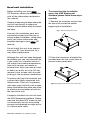
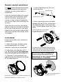
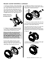
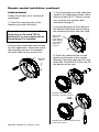
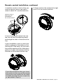
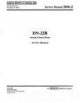
USER’S MANUAL
MR1620W
MR1620S
RDS Model with
Switchable USA/European
Frequencies
Fully Marinized MP3-Compatible
In-Dash CD Receiver
Congratulations on your
purchase of a
Marine
MP3/CD Receiver.
It has been designed, engineered
and manufactured to bring you
the highest level of performance
and quality, and will afford you
years of listening pleasure.
Thank you for making
Marine your choice for
marine audio entertainment!
page
CONTENTS
2
Head unit installation
4
Detaching the front panel
5
Removing the head unit
6
Remote control installation
Flush mount
6
Remote control installation
Surface mount
10
General and tuner controls
14
Remote control
15
CD Playback
15
MP3 playback
16
RDS radio functions
17
PTY station categories
18
Wiring diagram
19
Troubleshooting
20
Specifications
MR1620W • MR1620S Marine MP3/CD Receiver Packing List
Before installing your new
CD Receiver, please unpack the contents and check
that your package contains the following items:
Main unit
Detachable front panel with protective case
Mounting hardware for main unit:
Rear bracket plate
Rear mounting screw
Plain washer
Spring washer
Screw
Hex nut
Removal keys (2)
Wiring harness
Wired remote control
Remote control cable
Mounting hardware for remote control:
Mounting arms (2)
Mounting tube (1)
Machine screws (2)
User’s manual
Warranty card
MR1620W • MR1620S User’s Manual - page 1
Head unit installation
Before installing your new
CD Receiver, please become familiar
with all the information contained in
this manual.
To ensure that the installation
meets the IPX5 Waterproof
Standard, please follow these steps
carefully.
Choose a mounting location where the
unit will not distract or otherwise
interfere with the pilot’s ability to control
the boat.
1. Remove the transport screws from
the top of the enclosure before
beginning the installation.
Fig 1 Remove transport screws
Use only the installation parts and
hardware provided with the unit to
ensure proper installation. Using other
parts can cause malfunction and
possible damage to your
CD
receiver.
Do not install this unit at an angle in
excess of 30º from horizontal, as it
may affect performance.
Although this unit has been designed
for outdoor use, you can extend its life
if you install it in a location which is
not subject to extreme temperatures,
from such sources as heaters or
exhaust lines. Also, if you see dirt, dust
or debris on a disc or in the CD slot,
remove it with a clean cloth to avoid
pushing it into the player mechanism.
To remove dirt from the faceplate, use
a clean cloth lightly moistened with
filtered water. If the unit is splashed
with water, wipe it off with such a clean
damp cloth before the water has dried
to avoid an accumulation of salts on
the face of the unit.
If properly installed, this unit will meet
the IPX5 Waterproof standard. Please
note that this does NOT mean the unit
is submersible, but will resist being
sprayed and splashed as might occur
in a normal boat cabin.
MR1620W • MR1620S User’s Manual - page 2
2. Place the two pieces of plastic film
provided over the two screw holes to
prevent water penetration.
Figure 2 Apply plastic film to seal screw holes
English
Español
Português
Français
Deutsch
3. Insert and tighten the “headless”
support screw into the back of the
head unit where shown.
4. Insert the mounting case for the
head unit into the dashboard. Inspect
the dashboard material to determine
its approximate thickness. Select the
appropriate support tabs and bend
them outward to secure the bracket
in place (Figure 3).
mounting case
support screw
head unit
Figure 3 Bending the support tabs
5. Bend the backstrap to conform to
the mounting case and the dashboard
surface to which you plan to secure
the backstrap (Figure 4). Slide one of
the utility holes on the backstrap onto
the support screw and fasten it with
the spring washer and nut provided.
dashboard attachment
surface
support strap
5mm nut
6. Using the 5 x 25mm screw and the
plain washer, secure the backstrap to
the dashboard surface as shown in
the diagram. Tighten, secure, and
check the overall mounting to be sure
it is safe and will not release in an
emergency stop or other sudden
movement of the vehicle.
support screw
spring
washer
plain
washer
M5 x 25mm
support screw
Figure 4. Forming the support bracket
MR1620W • MR1620S User’s Manual - page 3
Detaching the front panel
1. Press the RELEASE button to lower
the front panel. (Figure 5).
3. Push the panel mechanism back
into the housing so it is not protruding.
To do so, push the BOTTOM EDGE
down straight into the unit – do not
lift it! (Figure 7).
RELEASE button
PUSH HERE in this direction
Figure 5 Press RELEASE to release the front panel
Figure 7 Push the panel mechanism back in
2. Press the panel release latch on
the front edge of the lower surface of
faceplate, and at the same time pull
the panel forward to disengage it from
the main unit. (Figure 6).
4. Immediately place the front panel
in its protective case for safe and
clean storage (Figure 8).
Front Panel
Figure 6 Press release latch on on the lower surface
of the front edge of the panel and pull the panel until it
is free of the head unit.
Figure 8 Place the front panel in its protective case
Be careful when handling the front panel!
1. Do not drop front panel.
2. When detaching or reinstalling, do not put pressure on the display.
3. Do not touch the contacts on the panel or the main unit body – doing so may result in poor electrical contact.
4. Dirt or foreign substances can be removed with a clean, dry cloth.
5. Do not expose the panel to high temperaturees or direct sunlight.
6. Do not permit volatile agents or solvents to contact the front panel.
7. Do not attempt to disassemble the front panel.
MR1620W • MR1620S User’s Manual - page 4
English
Español
Português
Français
Deutsch
Reinserting the front panel
Removing the head unit
1. Insert one side of the panel fully
into the opening in the main unit.
Should you need to remove the head
unit, first remove and store the front
panel as described on the preceding
page.
2. Then push the other end of the
front panel into the main body. You
should hear a “click.” (Figure 9)
NOTE: If the panel fails to lock into
position properly, the function of
some controls may be impaired,
and some segments of the display
may not become illuminated. If this
occurs, press RELEASE and reinstall
the front panel.
After you have removed the front panel,
insert the removal keys supplied with
the head unit into the two removal slots
as shown in the drawing until you feel
a “click.” You can now use the levers
to pull the unit from the mounting
surface. (Figures 10 and 11).
Removal key slots
Figure 9 Insert one end of the panel into the opening
in the main unit. Then push the other end of the
panel into main unit until you hear a “click”
Figure 10 Slots for removal keys
Figure 11 Insert removal keys until “click” occurs,
keys to pull out head unit.
MR1620W • MR1620S User’s Manual - page 5
Remote control installation
The
Marine Remote Commander
has been designed with particular
attention to ease and flexibility in
installation.
It can be mounted in both flush-mount
and surface mount situations. Both
use our exclusive “push and turn”
system. In both types of mountings,
you will first attach the mounting cup
in place.
Once the cup is secure, you simply
feed the wires thru the hole in the back
of the cup (flush mount) or the lower
edge of the cup (surface mount) and
then insert and turn the remote until it
is engaged.
4. Insert mounting arms fully into
mounting tube.
Mounting arms
Mounting tube
5. Insert mounting screws provided
through the slots in the cup and into
the threaded holes in the mounting
arms. Do not tighten more than a few
turns.
Insert the mounting screws through
the cup into the threaded holes
in the mounting arms
FLUSH MOUNT
Follow these steps for a successful
installation:
1. Select the proper location which
accomodates the 3.45” overall
diameter, and mark its centerpoint.
2. Drill a hole with diameter of 3.2”3.3” (82-84mm). It is very important
that the hole does not exceed 3.3”.
3. Place the O-ring provided in the
groove on the rear surface of the flange
of the mounting cup.
Place O-ring in groove on rear surface of flange of cup.
MR1620W • MR1620S User’s Manual - page 6
6. Insert this assembly fully into the
hole you have cut so that the flange
rests on the the mounting surface.
Be sure the cup is oriented with
arrow next to the word TOP is
pointing UP or your remote will be
turned when it is installed!
Insert the cup assembly fully into
the hole you have cut.
Remote control installation, continued
7. Using your fingers, grasp the heads
of the mounting screws and slide them
out, away from the center of the cup.
This will cause the mounting arms to
also slide out so that when you tighten
the screws, the ends of the arms will be
engaged behind the mounting panel.
10. Hold the remote in front of the cup
with the top up, and as you hold it, rotate
it about 20º counterclockwise.
20º
Slide the screws out to
extend the mounting arms
so that they reach behind
the mounting surface.
Hold the remote in front of
the cup, turned about
20º counterclockwise.
11. Insert the remote control fully into the
cup so that the mounting hooks penetrate
the slots in the back of the cup.
8. Tighten the screws equally until the
cup is firmly seated and the O-ring is
contacting the mounting surface.
If you feel resistance when you insert the
remote into the cup, pull the remote
housing and check that the cable has been
pressed into the curved slot, as described
in Step 2).
Please note: With the mounting arms
installed as shown (”pointing to the
front”), this mounting system can be
used on mounting surfaces up to about
3/4”. For thicker surfaces, you can
reverse the arms, which will permit
mounting to surfaces about 1” thick.
9. Press the cable into the curved
groove on the back of the remote
housing. Feed the cable end thru the
relief hole at the back of the cup.
12. Grasp and turn the remote to the right
until it is in the correct position.
MR1620W • MR1620S User’s Manual - page 7
Remote control installation, continued
SURFACE MOUNT
Follow these steps for a successful
installation:
1. Place the mounting cup in the
location you wish to install it.
Be sure the cup is oriented with
arrow next to the word TOP is
pointing UP or your remote will be
turned when it is installed!
Using screws of suitable size and type
for your application, attach the cup to
the mounting surface. If necessary,
drill pilot holes for the screws first.
Mounting
surface
2. If you are going to run the cable into
a hole in the mounting surface, drill a
hole of at least 9/16” (15mm) so that
you can pass the remote cable
connector through it.
If you are going to run the cable out
the bottom relief hole and out along
the mounting surface, skip this step.
Drill a 9/16”
(15mm) or
larger hole to
allow cable to
pass through
mounting
surface.
3. Press the cable into the curved
groove on the back of the remote
housing. Feed the cable end thru the
relief hole at the BACK of the cup OR
the bottom of the cup.
Intallation with cable going
into hole in mounting surface.
- OR -
Intallation with cable running out on top
of mounting surface.
MR1620W • MR1620S User’s Manual - page 8
Remote control installation, continued
4. Hold the remote in front of the cup
with the top up, and as you hold it,
rotate it about 20º counterclockwise.
6. Grasp and turn the remote to the right
until it is in the correct position.
Hold the remote in
front of the cup,
turned about
20º counterclockwise.
20º
5. Insert the remote control fully into
the cup so that the mounting hooks
go through the slots in the back of the
cup.
If your installation is one in which the
cable is exiting out the bottom of the
housing (NOT the back), as you insert
the remote module pull the cable down
gently so it does not interfere with the
insertion of the remote into the cup.
If you feel resistance when you insert
the remote into the cup, pull the remote
housing out and check that the cable
has been pressed into the curved slot,
as described in Step 3).
MR1620W • MR1620S User’s Manual - page 9
General and Tuner Controls
1
2
3
MR1620W MARINE CD RECEIVER
TUNE•TRK
TUNE•TRK
MUTE
60W
X
4 CH
MO
6
AS
AF
4
POWER
SELECT
PTY
1
MODE
EQ
MP 3/ C DR / CD R W PLAYB A C K
DISP
5
2
+10
3
-10
4 REPEAT
5
RANDOM
6
EON
INTRO
BAND
LOUD TA
RELEASE
SCAN
EJECT
AUX IN
9a
7
8
9b
1 VOLUME UP/DOWN BUTTONS
In normal operation, these buttons are
used to increase or decrease the volume
level.
Used in combination with the SELECT
button, these buttons are used to increase
or decrease the settings of various audio
parameters.
2
TUNE/TRACK BUTTONS
In Radio mode, press these buttons
briefly to step up or down the radio dial
in single step increments. Press and hold
for more than one-half second and the
tuner will enter the SEEK mode. In this
mode the tuner will stop at the next strong
station available.
In CD mode, pressing these buttons
briefly will advance the player to the next
(or previous) track. Press and hold and
the player will enter SEARCH mode.
3 PLAY/PAUSE, MUTE
In CD mode, discs will begin playback
automatically upon insertion. To pause
playback, press this button. Press again
to resume playback.
In Radio, AUX and AUX 1 modes,
Press this button to silence the audio.
Press again to restore the previous audio
volume level.
MR1620W • MR1620S User’s Manual - page 10
9c
9
13
9d
10
11 12
14
4 DISPLAY (Clock display and setting)
Press this button briefly to display the
current time. To reset the time, press
and hold this button until it begins
flashing. Then you can use the
UP/DOWN buttons to change the hour
and minutes.
5 POWER
Press this button to turn unit on. Press
again to turn it off.
6 MODE (Input Select)
Press this button repeatedly to cycle
through the audio input sources in the
following order:
RADIO > CD > AUX > AUX 1 (front panel
aux input)
To clear all stored memories, press and
hold this button for several seconds.
15
16
17
7 SELECT
The SELECT button is used to access a
wide range of settings for the receiver.
AUDIO SETTINGS
To change settings in the audio section,
press SELECT briefly, repeatedly, to step
thru the following audio parameters:
VOLUME > BASS > TREBLE > BALANCE
> FADER
Use the UP/DOWN buttons to change the
settings as desired. If you have made a
change to a setting, press SELECT to enter
it and move to next parameter. When you
are finished making settings, after about 5
seconds the unit will return to normal mode.
Please note: If you have selected a preset EQ
curve, the settings for BASS and TREBLE will
not be available in the Audio Settings section.
SYSTEM SETTINGS
General Settings
To access system setup items, press and
hold SELECT for more than two seconds.
The LCD will display “MENU” and then will
display the first adjustable item, which is
“CLOCK.”
Press SELECT briefly to step thru the
available settings. Use the UP/DOWN
buttons to make any changes. The
following list shows the sequence of items
in the menu, and the choices possible. The
factory default is indicated in bold type.
• Clock 12HR/24HR: 12HR or 24HR In
areas with US frequencies 12 HR, in areas
with European frequencies, 24HR.
• CT (Clock time): If the frequency area
switches from American to European, the
clock will display 24:00. Similarly if the area
switches from European to American, the
clock will display 12:00. Use the UP/DOWN
buttons to adjust the minutes or hours.
• Subwoofer channel: ON/OFF
• LOC/DX radio reception: LOC/DX
• Area: Factory set to the country in which
the radio is sold. Europe > Latin > OIRT
> AUST > ASIA > USA
• Beep (when you press a button): ON/OFF
• Clock On (determines if clock will be
displayed when radio is turned off):
ON/OFF
• LCD1/2 (LCD brightness level): 1/2
RDS Radio Settings
• SEEK RDS/ALL
This setting determines the behavior of
the radio SEEK function when RDS tuning
mode. If ALL is selected, the SEEK
function will stop at both RDS and nonRDS stations. Otherwise, it will only seek
RDS stations. RDS/ALL
• TA (Traffic Alert) SEEK/ALARM
When TA mode is on, the radio monitors
the Public Information channel which is
piggy-backed on the FM channel you are
currently enjoying. If such a channel is not
detected or is weak the tuner will SEEK
another PI channel and monitor it.( This
is the TA SEEK setting).
If ALARM setting is chosen, if a signal is
insufficiently strong, instead of monitoring
an alternate station for PI information, the
radio will produce a double beep (alarm)
and silence itself, and display “LOST TP
TA.” TA SEEK/ALARM
• TA VOLUME
This setting determines the volume level
of the Traffic Alerts as they play.
0-40 (18 is default)
• REG ON/OFF
This setting determines the behavior of
the radio reception when AF (Alternate
Frequency) mode is on. The AF system
continuously monitors the signal strength
of a station and compares it with other
stations on the same network. If another
station is stronger, it changes to that
station.
Since sometimes in different regions
stations on the same network will play
different programs, the AF system can
interrupt the current program. If REG ON
is selected, the station will check if the
programs are the same, and if not, the TA
system will not change the station.
REG OFF/ON
• V-PGM (maximum volume level): 0-12
MR1620W • MR1620S User’s Manual - page 11
General and Tuner Controls, continued
1
2
3
MR1640W MARINE CD RECEIVER
WITH WEATHER BAND
TUNE•TRK
TUNE•TRK
MUTE
60W
X
4 CH
MO
6
AS
AF
4
5
SELECT
PTY
1
MODE
EQ
MP 3/ C DR / CD R W PLAYB A C K
DISP
POWER
2
+10
3
-10
4 REPEAT
5
RANDOM
6
INTRO
EON
BAND
LOUD TA
RELEASE
15
16
17
SCAN
EJECT
AUX IN
9a
7
8
9b
9
8 LOUDNESS/TA
Press briefly increase the level of bass
output. Press again to turn off the
Loudness function.
Press a little longer to turn on the TA
(Traffic Alert) mode. For more information
about this mode, please see page 16
of this manual)
9 PRESETS 1-6 (Radio Mode)
These buttons are used to store the
presets for radio stations. To set a preset,
tune to the desired radio station. Then
press and hold the preset to which you
wish to assign that station for more than
one second and release. To replace it
with a different station, repeat the
process and the new setting will override
the previous one.
9a +10/-10 (next/previous 10 tracks)
These button are used during disc
playback to skip ahead or back ten
tracks.
9b REPEAT
In CD Playback Mode, when you press
this button briefly, the player will keep
repeating the same track until you press
it again.
In MP3/WMA Playback Mode, when
you press this button, the player will
keep repeating the same track until you
press it again. Press and hold this button
to repeat all the tracks in the current
folder.
9c
13
9d
10
11 12
14
9c RANDOM
In CD Playback Mode, pressing this
button will cause the player to play all
the songs on the current disc in random
order.
In MP3/WMA Playback Mode, press
and hold this button and the player will
play all the songs in the current folder
in random order.
In both modes, press RANDOM again
to cancel the Random playback mode.
9d INTRO SCAN
The Intro Scan function is a convenient
way to find a particular track.
In CD Playback Mode, press this button
and the player will play the first few
seconds of a song, and then skip to the
next song and play a few seconds of that
song. This process continues until you
press the INTRO button again, and the
player will continue playing that song.
In MP3/WMA Playback Mode, press and
hold this button and the player will play
the first few seconds of a song in the
current folder, and then skip to the next
song and play a few seconds of that song.
This process continues until you press
the INTRO button again, and the player
will continue playing that song.
10 AUX IN JACK
This jack is a convenient way to play
music from an MP3 music player such
as an iPod through your marine stereo.
Simply connect the headphone output
of the MP3 player to this input jack, and
use the CD Receiver’s MODE button to
select AUX 1 as input source and begin
playing music on the MP3 player.
MR1620W • MR1620S User’s Manual - page 12
11 RELEASE
16 MO/ST, AF (Alternate Frequency)
To remove a disc or take off the front
panel, first press this button to lower
the panel.
To remove the front panel, please see
the instructions on page 4.
12 BAND
Press briefly, repeatedly to cycle between
the radio bands:
FM1 > FM2 > FM3 > AM1 > AM2 >
13 EJECT
To eject a disc, you must first open the door.
Then press this button and the disc
mechanism will move the disc out to where
you can grab it and remove it safely.
14 SCAN, EON ON/OFF
In Radio mode, when you press this
button briefly the tuner will scan up the
band until it detects a strong station.
Then it will stop, and the frequency of
that station will be displayed in a flashing
pattern for about 5 seconds. If you wish
to hear this station, press SCAN again.
If you do not push SCAN, the tuner will
scan up to the next station and repeat
the same pattern.
To turn on EON mode of RDS System,
press and hold this button. When the
EON function is turned on, “EON” will
be displayed on the screen (for more
information about the EON function see
page 16).
15 AS/PS (Automatic preset setup,
preset scan function)
When pressed and held for several
seconds, the tuner will search and store
the first six strong stations as presets in
the current radio band.
If you are dissatisfied with the quality
of the reception in stereo, switching to
mono often improves the overall sound
quality. To do this, press this button
briefly.
Press and hold this button to turn on
the RDS AF function, which compares
the signal strength of the current station
with others on the same network and
changes to improve reception. See page
16 for more information.
17 EQ (Preset Equalizer Curves)
PTY (RDS Program Type Tuning)
Press briefly, repeatedly to cycle through
five modes: POP > JAM > JAZZ > ROCK
> CLASSICAL > FLAT > OFF.
Press and hold this button to turn on the
PTY function and begin RDS tuning radio
stations. For information on assigning
using the PTY function, please see page
17 of this manual.
18 RESET
If you experience abnormal functioning
of the unit, try turning the unit off and
back on again about ten minutes later.
If problems persist, remove and carefully
reinsert the front panel, making sure it is
fully seated. If problems continue, remove
the panel again and clean the connector
on the back of the panel with a cotton
swab moistened with isopropyl (rubbing)
alcohol.
If you still have problems, press the reset
button with a small pointed object such
as a ball point pen. This will restore all
factory defaults to the unit, which includes
clearing your radio presets.
Press this button briefly, repeatedly to
step between and listen to the six presets
of the current band.
RESET button
18
MR1620W • MR1620S User’s Manual - page 13
Remote Control
1 POWER
Use to turn CD Receiver ON or OFF.
2 MODE
Press to choose desired audio source:
RADIO > CD > AUX > AUX 1 (front
panel aux input)
3 BAND
Press briefly, repeatedly to cycle
between the radio bands:
1
3
BAND
TUNE • TRACK
FM1 > FM2 > FM3 > AM1 > AM2 >
MUTE
4 SCAN/EON ON/OFF
2
In Radio Mode, when you press
this button briefly the tuner will
scan up the band until it detects
a strong station. Then it will stop,
and the frequency of that station
will be displayed in a flashing
pattern for about 5 seconds. If
you wish to hear this station,
press SCAN again. If you do not
push SCAN, the tuner will scan
up to the next station and repeat
the same pattern.
To turn on EON mode of RDS
System, press and hold this
button. When the EON function
is turned on, “EON” will be
displayed on the screen (for more
information about the EON
function see page 14).
5 TUNE/TRACK
(
and
)
In Radio Mode, press and release to
activate automatic seek function
(”AUTO” will appear on display). Press
and hold to engage manual tuning
mode (”MANUL” will appear on
display).
In CD Mode, press and release to
advance to the next track or to return
to the beginning of the current track
(track number will be displayed). Press
and hold to fast forward or reverse.
Play will begin at the point when you
release the button.
MR1620W • MR1620S User’s Manual - page 14
MODE
SCAN
EON
VOLUME
MARINE REMOT E COMMANDER
5
6
7
8
6 PLAY/PAUSE
Discs will begin playback automatically
upon insertion. To pause playback, press
this button. Press again to resume
playback.
7 VOLUME Use to increase or decrease
volume level.
8 MUTE
In Radio, AUX and AUX 1 modes,
press this button to silence the audio.
Press again to restore the previous audio
volume level.
Please note: MUTE is not available in
Disc Playback modes.
4
CD playback
MP3 disc playback
Please follow these general instructions to
play a music CD disc. On the column to
the right, you will find instructions for using
MP3 discs.
When you insert an MP3 (or WMA) disc,
the player will begin playback from the first
track in the directory.
Please note that only some of these
functions are available on the remote control.
However, MP3 discs can contain many
more tracks than audio CD’s, so you may
wish to search for a particular track to play.
There are two search methods available.
Loading a disc
Press the RELEASE button to lower the
front panel. This will expose the disc slot.
TRACK SEARCH MODE
In disc playback mode, press the BAND
button once. The LCD will display the word
“TRACK.”
To begin searching, press SELECT or the
UP/DOWN button. Then press and hold
the UP or DOWN button to locate the
desired track, and press SELECT to begin
playback.
Gently insert disc until it is drawn in
by player mechanism.
Gently insert a disc into the disc slot until
you feel it being drawn in by the player
mechanism. If there is already a disc in the
player, first press EJECT to eject it and
remove it.
Playing a disc
The disc will begin playing automatically. If
you wish to pause playback, press
PLAY/PAUSE, and press again to resume
playback.
To start playback from the first track, press
PRESET 1. To skip ahead or back ten tracks
on the disc, press the +10 or -10 button.
Intro Scan function
The Intro Scan function is a convenient way
to find a particular track. Press this button
and the player will play the first few seconds
of a song, and then skip to the next song
and play a few seconds of that song. This
process continues until you press the INTRO
button again, and the player will continue
playing that song.
Repeating a track
To keep repeating the same track, press
the REPEAT button. To cancel the repeat
function, press again.
NAVIGATE THE CURRENT FOLDER
This mode permits you to navigate the file
directory present on the disc.
To enter this mode, press BAND twice. The
display will display “NAVIGA.” Press
SELECT to enter this mode.
Use the UP and DOWN buttons to move
up and down the directory of folders and
files on the disc. To enter a subfolder ,
highlight it and press SELECT. You will then
see the directory of that subfolder and can
select tracks within it. So play a track,
highlight it and push SELECT.
VIEWING MP3 FILE INFORMATION
Since many MP3 files are tagged with
Music/Artist/Album (ID3-TAG) information,
you can see this as a list by pressing AS/PS
repeatedly.
The information will appear as a scrolling
display, including the folder and file name
as well as the ID3-TAG information.
Please note that if this information is not
present in ID3-TAG version 1.0 or 2.0 format,
it will not be displayed.
Random play
Pressing the RANDOM button will cause
the player to play all the songs on the current
disc in random order. Press again to cancel
this function.
MR1620W • MR1620S User’s Manual - page 15
RDS Radio functions
The RDS (Radio Data System) is a digital
information system created by the European
Broadcast Union (EBU).
This system “piggy-backs” a variety of
information services onto normal FM
broadcasts. This information can only be
decoded by a radio with RDS decoding, like
this model.
RDS EON function setting
The RDS EON system extends the
functionality of the TA sensing to a wider
range of traffic announcements from both
local and national sources. It also allows the
unit to interrupt disc playback with these
announcements. In addition, it will play these
announcements (at normal listening level)
even if the audio has been muted.
The three main RDS functions are described
below:
(To set this level, see instructions on page
11 for setting V-PGM level).
AF/REG (Alternate Frequency)
When this mode is enabled by pressing and
holding the MO/ST•AF button, the radio will
continuously monitor the signal strength of
the broadcast you are listening to and if it
finds the same network broadcast on a
different frequency which is stronger, it will
automatically switch to the stronger signal.
To enable the EON function, press and hold
the SCAN button. Press again to disable it.
Regional mode setting
In the SELECT menu (see page 11 in this
manual) you can choose to turn on or off the
REG (regional mode) subfunction within AF
mode. The default mode is OFF.
Although the AF button can sense if one
station on a network is stronger than another,
it will not confirm that the actual program
being broadcast is the same unless you turn
ON the REG mode.
TA (Traffic Announcement)
Many FM stations offer traffic
announcements in addition to their regular
programming.
If you enable the TA function by pressing
the TA button, when this station broadcasts
a traffic advisory, the radio’s RDS tuner will
automatically interrupt the regular program
and play the alert. When the alert is finished,
normal play of the broadcast will resume.
The TA function will also interrupt CD and
MP3 playback temporarily if the EON feature
has been enabled (see below).
There are some other settings for TA
behavior that you can change. See the
SELECT instructions on page 11 for more
information.
MR1620W • MR1620S User’s Manual - page 16
With EON enabled, when a traffic
announcement is broadcast, the radio will
switch automatically to TA mode, and “TP”
(Traffic Program) will be displayed.
PTY Station Categories
PTY (Program type)
A number of RDS stations can be selected
by the type of program they broadcast, i.e.
news, sport or classical music.
Press and hold the PTY button to cause the
tuner to switch to RDS PTY type tuning. If at
any time you wish to return to normal tuning
mode, press and hold again.
When you have entered PTY mode, the
display will show “PTY” indicating that the
mode is enabled, and the name of the first
program type, “NEWS.”
To view other PTY categories, use the
UP/DOWN buttons (a list of these categories
is shown on the next page). To select the
category, highlight it and press SELECT. If
there is no station found in that category, the
display will show “NONE PTY” and the radio
will return to normal mode.
This list shows the PTY program types in the
order presented in the radio display:
NEWS
AFFAIRS
INFORMATION
SPORTS
EDUCATION
DRAMA
CULTURE
SCIENCE
VARIETY
POP MUSIC
ROCK MUSIC
EASY LISTENING MUSIC
LIGHT MUSIC
CLASSICAL MUSIC
OTHER MUSIC
WEATHER
FINANCE
CHILDREN
SOCIAL
RELIGIOUS
PHONE IN
TRAVEL
LEISURE
JAZZ MUSIC
COUNTRY MUSIC
NATIONAL MUSIC
OLDIES MUSIC
FOLK MUSIC
DOCUMENTARY
ALERT TEST
ALARM TEST
MR1620W • MR1620S User’s Manual - page 17
Wiring diagram
Follow the wiring illustration below closely to obtain proper performance from your CD
receiver. Failure to make these connections properly may result in damage to your unit
which will not be covered under your warranty.
This receiver contains a built-in high power four-channel amplifier. To use the built-in
amplifier, connect the speaker wires as shown. To use the receiver as a head unit in a
2CH, 4CH or 4CH-plus-subwoofer mobile audio system which includes an amplifier(s)
or power subwoofer, use the RCA outputs to connect to the RCA inputs of your amplifier(s).
RIGHT CH (RED)
SUBWOOFER OUTPUT
AUX AUDIO INPUTS
BLACK
LEFT CH (WHITE)
to optional
SUBWOOFER AMPLIFIER
OR POWERED SUBWOOFER
TO MARINE COMMANDER
(REMOTE CONTROL)
REMOTE CONTROL CONNECTOR
to Antenna
Antenna
connector
RIGHT CH (RED)
FRONT AUDIO OUTPUTS
RIGHT CH (RED)
REAR AUDIO OUTPUTS
BROWN CABLE
LEFT CH (WHITE)
GREY CABLE
LEFT CH (WHITE)
ISO CONVERSION
CONNECTOR
OPTIONAL POWER AMPLIFIER
Ignition switch
(ACC +)
RED
Constant 12V
(BATT +)
YELLOW
WARNING!
ANTENNA cannot contact GROUND
or damage may result!
Ground (BATT -) BLACK
Power Antenna BLUE
LEFT FRONT SPEAKER
WHITE
+
WHITE/BLACK
–
SPEAKER IMPEDANCE
MINIMUM 4 OHMS!
LEFT REAR SPEAKER
GREEN
+
GREEN/BLACK
–
MR1620W • MR1620S User’s Manual - page 18
RIGHT FRONT SPEAKER
GREY
GREY/BLACK
RIGHT REAR SPEAKER
VIOLET
VIOLET/BLACK
SPEAKER IMPEDANCE
MINIMUM 4 OHMS!
Troubleshooting
If you experience operation or performance problems with this product, compare your
installation with the electrical wiring diagram on the previous page. If problems persist,
read the following troubleshooting tips which may help eliminate the problems.
SYMPTOM
No power.
Disc cannot be
loaded or ejected.
No sound.
Sound skips.
Buttons on front
panel do not
operate.
Radio does not
work, or the
radio automatic
selection function
does not work.
CAUSE
REMEDY
The car ignition switch
is not on.
If the head unit is properly connected
to the car accessory power circuits,
but the engine is running, switch the
ignition key to the “ACC” position.
The fuse is blown.
Replace the fuse.
There is a disc already in
the CD player.
Remove disc in player and try again.
Disc is inserted upside
down.
Insert the disc with the label facing
up.
Disc is dirty or defective.
Clean the disc, or play a new one.
Car interior temperature
is too high.
Allow temperature to cool down to
a normal level.
Excess atmospheric
humidity or condensation
is present.
Leave player off for an hour or so,
and then try again.
Volume is set to minimum.
Adjust volume to desired level.
Wiring not properly
connected.
Check wiring connections.
Head unit is installed at an
angle of greater than 30º
from horizontal.
Adjust installation angle to less than
30º from horizontal.
Disc is dirty or defective.
Clean the disc, or play a new one.
The built-in microprocessor is not operating
properly due to noise.
Press the RESET button.
Front panel is not properly
fixed in place.
Remove front panel, press
RESET button, and re-insert
front panel.
Antenna cable not
connected.
Insert the antenna cable firmly
into connector.
The signals are too weak
to be received properly.
Select station manually.
MR1620W • MR1620S User’s Manual - page 19
Specifications
MR1620W • MR1620S
Fully-Marinized MP3-Compatible In-Dash CD Receiver • RDS Model with Switchable USA/European Frequencies
CD PLAYER
Signal-to-noise ratio
Frequency response
Compatible formats
Greater than 50dB @ 1kHz
20Hz - 20kHz
CD, CD-R, CD-RW, MP3, WMA
RADIO
FM Section:
Frequency range
Usable sensitivity
Intermediate frequency
87.5 - 108MHz (EUROPE), 87.5 - 107.9MHz (USA)
3uV
10.7MHz
AM Section:
Frequency range
Usable sensitivity
Intermediate frequency
522 - 1620kHz (EUROPE), 530 - 1710kHz (USA)
40dB
450kHz
AMPLIFIER
Maximum output power
60 watts x 4 channels
GENERAL
Power supply req.
Current consumption
Line out voltage
Chassis dimensions
(W X H X D)
12VDC, negative ground
15A Max
1200mV
7” x 2” x 6.4” (178 x 50 x 178 mm)
All specifications subject to change without notice.
MR1620W • MR1620S User’s Manual - page 20