1
TM-157
1st printing
Sanyo 14" Color TV Monitor
~-- -,
~
I
I
I
I
I
I
I
Operation, Maintenance
and Service Manual
Complete with Illustrated Parts List
JI\.
ATARI®
I
..J
I
Cl
A Warner Commun1ca1tons Company
Sanyo 14" Color TV Monitor
Operation, Maintenance
and Service Manual
Complete with Parts Lists
Monitor manufactured by Sanyo Electric Co., Ltd.
Color TV Receiver Manufacturing Division
Gifu, Japan
Published by:
ATARI INC
1265 Borregas Avenue
P. 0 . Box 427
Sunnyvale, California 94086
Copyright © 1980 by Atari, Inc.
All rights reserved.
No part of this publication may be reproduced by any mechanical, photographic, or electronic process, or in the form of a phonographic recording, nor
may it be stored in a retrieval system, transmitted, or otherwise copied for
public or private use, without permission from the publisher.
Lithographed in the U.S.A.
7J
A Warner Communications Company
Cl
Sanyo Color Monitor
Table of Contents
1
Warnings and Cautions
A.
B.
C.
D.
E.
2
B.
C.
D.
E.
F.
2
2
Power Input and Consumption . . . . . . . . . . . . . . . . . . . . . . . . . . . . . . . . .
Temperatures and Humidity . . . . . . . . . . . . . . . . . . . . . . . . . . . . . . . . . . .
Currents and Voltages. . . . . . . . . . . . . . . . . . . . . . . . . . . . . . . . . . . . . . . .
CRT Specifications . . . . . . . . . . . . . . . . . . . . . . . . . . . . . . . . . . . . . . . . . .
Connectors . . . . . . . . . . . . . . . . . . . . . . . . . . . . . . . . . . . . . . . . . . . . . . . .
Pattern Size . . . . . . . . . . . . . . . . . . . . . . . . . . . . . . . . . . . . . . . . . . . . . . . .
3
3
3
3
3
3
Adjustable Controls
A.
B.
C.
D.
E.
F.
4
1
1
1
Specifications
A.
3
Before You Start . . . . . . . . . . . . . . . . . . . . . . . . . . . . . . . . . . . . . . . . . . . . .
Safety Measures . . . . . . . . . . . . . . . . . . . . . . . . . . . . . . . . . . . . . . . . . . . .
Picture-Tube Handling. . . . . . . . . . . . . . . . . . . . . . . . . . . . . . . . . . . . . . . .
Replacing with Proper Components . . . . . . . . . . . . . . . . . . . . . . . . . . . . .
Final Testing Before Reinstalling Monitor . . . . . . . . . . . . . . . . . . . . . . . .
Brightness . . . . . . . . . . . . . . . . . . . . . . . . . . . . . . . . . . . . . . . . . . . . . . . . .
Horizontal Hold . . . . . . . . . . . . . . . . . . . . . . . . . . . . . . . . . . . . . . . . . .. . . .
Vertical Hold . . . . . . . . . . . . . . . . . . . . . . . . . . . . . . . . . . . . . . . . . . . . . . .
Vertical Height . . . . . . . . . . . . . . . . . . . . . . . . . . . . . . . . . . . . . . . . . . . . . .
Horizontal Width . . . . . . . . . . . . . . . . . . . . . . . . . . . . . . . . . . . . . . . . . . . .
Focus .....................................................
4
5
5
5
5
5
Supply Voltages and Test Points
For text see page . . . . . . . . . . . . . . . . . . . . . . . . . . . . . . . . . . . . . . . . . . . . 6
5
Signal Test Points
A.
B.
6
Red, Green, Blue Signals. . . . . . . . . . . . . . . . . . . . . . . . . . . . . . . . . . . . . . 6
Horizontal and Vertical Sync . . . . . . . . . . . . . . . . . . . . . . . . . . . . . . . . . . . 6
Troubleshooting
For block diagram of Sanyo monitor see page . . . . . . . . . . . . . . . . . . . . . 7
7
Repair
A.
B.
C.
ii
Picture Tube Replacement . . . . . . . . . . . . . . . . . . . . . . . . . . . . . . . . . . . . 8
Yoke Replacement. . . . . . . . . . . . . . . . . . . . . . . . . . . . . . . . . . . . . . . . . . . 8
Flyback Transformer Replacement . . . . . . . . . . . . . . . . . . . . . . . . . . . . . . 8
Sanyo Color Monitor
8
Adjustments
A.
Purity Adjustment . . . . . . . . . . . . . . . . . . . . . . . . . . . . . . . . . . . . . . . . . . .
1. Preliminary . . . . . . . . . . . . . . . . . . . . . . . . . . . . . . . . . . . . . . . . . . . . .
2. Red Purity Adjustment . . . . . . . . . . . . . . . . . . . . . . . . . . . . . . . . . . . .
3. Green Purity Adjustment . . . . . . . . . . . . . . . . . . . . . . . . . . . . . . . . . .
4. Blue Purity Adjustment. . . . . . . . . . . . . . . . . . . . . . . . . . . . . . . . . . . .
5. Final Check . . . . . . . . . . . . . . . . . . . . . . . . . . . . . . . . . . . . . . . . . . . . .
Convergence Adjustments . . . . . . . . . . . . . . . . . . . . . . . . . . . . . . . . . . . .
1. Static Convergence (Center Area) . . . . . . . . . . . . . . . . . . . . . . . . . . .
2. Dynamic Convergence (Outer Area) . . . . . . . . . . . . . . . . . . . . . . . . .
B.
9
9
9
9
9
9
9
9
9
11
Schematic and Illustrated Parts Lists
For drawings see page . . . . . . . . . . . . . . . .. . . . . . . . . . . . . . . . . . . . . . . . 12
(
List of Illustrations
(
Figure 1
Figure 2
Figure 3
Figure 4
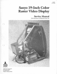
Overview of Sanyo 14" Color TV Monitor . . . . . . . . . . . . . . . . . . . . . .
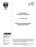
Adjustable Controls on Main PCB and Control PCB . . . . . . . . . . . . .
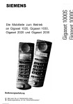
Adjustable Controls on Neck PCB . . . . . . . . . . . . . . . . . . . . . . . . . . .
Block Diagram of Sanyo Monitor. . . . . . . . . . . . . . . . . . . . . . . . . . . . .
1
4
5
7
Figure
Figure
Figure
Figure
Schematic Diagram of Sanyo Monitor .........................
Main PCB Assembly .......................................
Neck PCB Assembly ......................................
Parts List of Sanyo Monitor .................................
10
12
13
14
5
6
7
8
•
iii
7-
Sanyo Color Monitor
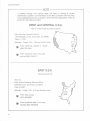
If reading through this manual does not lead to solving a certain
maintenance problem, call Tele-Help™ at the Atari Customer Service office
in your geographical area, as shown in one of the two maps below. Order all
parts from the California office.
WEST and CENTRAL U.S.A.
Parts for all Atari Customers. Sales and Service
Atari Coin-Op Customer Service
1344 Bordeaux Drive, Sunnyvale, CA 94086
Telex 17-1103
(Monday - Friday, 7:30 - 4:00 pm Pacific Time)
From California, Alaska or Hawaii
(408) 745-2900
From anywhere else in this area
toll-free (800) 538-1611
EAST U.S.A.
Sales and Service Only
Atari Inc.
New Jersey Customer Service Office
Cottontail Lane, Somerset, NJ 08873
Telex 37-9347
(Monday - Friday, 7:30 - 4:00 pm Eastern time)
iv
s
From New Jersey
(201) 469-5993
11:
From anywhere else in this area
toll-free (800) 526-3849
Sanyo Color Monitor
1 Warnings and Cautions
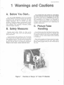
A. Before You Start...
You should never attempt to work on an exposed
monitor chassis if you are not familiar with servicing
procedures and precautions necessary for highvoltage equipment. Any TV monitor has three
sources of possible danger: strong electric shock
due to high voltages or unisolated AC line voltages,
X-ray radiation, and implosion. Therefore, please
read this chapter carefully.
B. Safety Measures
Develop good safety habits, so when you're
rushed with repair work, you'll still automatically
take precautions.
A good practice when working on any TV monitor
is to first ground the chassis and use only one hand
when testing circuitry. This will avoid the possibility
of carelessly putting one hand on the chassis or
ground, and the other on an electrical connection.
Doing so could cause a severe electrical shock.
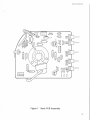
Figure 1
If you service this color monitor on a test bench,
you must isolate the monitor from AC line voltage!
An isolation transformer is mandatory for your own
safety. The Sanyo monitor does not contain an isolation transformer on its chassis. It is mounted instead on the game power supply. (It may appear like
a regular power transformer, but is really also an
isolation transformer.)
C. Picture·Tube
Handling
Use extreme care when handling the picture tube,
since rough handling may cause it to implode, due
to a vacuum inside. Do not nick or scratch the glass,
or subject it to any undue pressure when removing
or installing it.
Wear safety goggles and heavy gloves for protection when handling the picture tube. Keep others
without safety goggles away. Do not lift the tube by
the neck.
Overview of Sanyo 14" Color TV Monitor
1
Sanyo Color Monitor
Discharge the high voltage in the picture tube by
shorting the anode connection to chassis groundnot the cabinet or other mounting parts. When
discharging, go from ground to anode, and use a
well-insulated piece of wire.
D. Replacing with
Proper
Components
It is important to maintain the specified values
and failure characteristics of all components in the
horizontal and high-voltage circuits, and anywhere
else in the monitor that could cause a rise in high
voltage, or in operating supply voltages.
Refer to the parts lists in the back of this manual,
and use only exact replacement parts, especially for
the picture tube, semiconductors, transformers,
coils, and fuses.
2
If you replace the picture tube with another type
not specified in the parts list, then avoid prolonged
exposure at close range to the unshielded areas of
the tube. You may endanger yourself from unnecessary exposure to X-ray radiation.
E. Final Testing Before
Reinstalling Monitor
Before installing the color monitor back in the
game, you must check the following:
1.
Inspect all harness wiring on the monitor and be
sure none of it is pinched between the chassis
and other metal parts in the monitor.
2.
Replace all protective devices such as insulating fishpaper, compartment covers and
shields.
Sanyo Color Monitor
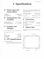
2 Specifications
A. Power Input and
Consumption
Line Voltage
Line Frequency
Power Consumption
A.C. 100V ± 10%
50/60 Hertz
46 Watts
Purity-Color purity should be practically uniform
all over screen after being degaussed with handheld degaussing coil
Pull-In Range, Horizontal
Pull-In Range, Vertical
15.75 KHz ± 200 Hz
More than 8 Hz
Type of CRT
#370ECB22, 14-lnch, 90°
B. Temperatures and
Humidity
Tilt of Deflection Yoke
Environmental Temp.
Environmental Humidity
Temp. Inside Game Cabinet
6-Pin Connector for Video Signals:
Pin 1 =Red
Pin 2 =Green
Pin 4 =Ground
5-35° C (41-95° F)
20-95%
45° C max. (112° F)
declination is within 2 mm
E. Connectors
3-Pin Connector for Power:
Pin 1=100 VAC
C. Currents and
Voltages
The CRT anode average current is less than 650 uA.
Pin 3 =Blue
Pin 5=Sync
Pin 2=100 VAC
F. Pattern Size
You should be able to reproduce the following sLz;es
of patterns:
High voltage is 24 ± 1.5 KV.
B+ 1
B+ 2
B + 3 (regulated)
B + 4 (regulated)
Heater Voltage
105 ± 1.0 v
19.5 ± 2.0 v
12 ± 1.0 v
175 ± 5.0 v
6.4 ± 0.2 V (RMS)
Maximum size
D. CRT Specifications
Convergence Tolerancemax. 0.2% of raster width, center of screen
max. 0.5% of raster width, corners of screen
Minimum size
CRT
_.,.
3
Sanyo Color Monitor
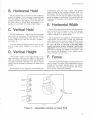
3 Adjustable Controls
A. Brightness
Remember to observe the precautions regarding
high voltages when you make any adjustments on
this monitor!
However, if you cannot achieve the proper
brightness by using this white adjustment knob,
then you should check the master brightness level
adjustment. This potentiometer is located almost
dead center on the Main PCB, at VR201.
Note that before you adjust the brightness, the
monitor should have been turned on for at least 5
minutes. Keep the game in the attract or play mode.
Find the small white knob underneath the screen,
located at the far right on the Control Printed-Circuit
Board or PCB (see Figure 2). Turn this brightness or
screen voltage control until you achieve a pleasing
level of brightness.
To reset the brightness level, disconnect the 6-pin
video-signal connector from the monitor. Turn the
white brightness control to maximum or fully clockwise. Connect a DC voltmeter's plus lead to TP452,
and its minus lead to TP451-near the center of the
Main PCB.
Too high a brightness causes the retrace lines to
show. Too low a brightness causes the entire screen
to become dark and obscured.
Set the voltmeter to the 1.5-3 V range. Now adjust
the small VR201 potentiometer to 0.5 volts. Reconnect the 6-pin connector on the monitor.
HORIZONTAL
HOLD
VERTICAL
HOLD
VERTICAL
HEIGHT
MAIN PCB
BRIGHTNESS
LEVEL
~
TP451
TP452
0
0
HORIZONTAL
WIDTH ADJUST·
MENT COIL
B + ADJUSTMENT
(For Technicians Only)
Figure 2
4
@
Adjustable Controls on Main PCB and Control PCB
Sanyo Color Monitor
B. Horizontal Hold
Use this adjustment if the picture drifts sideways
across the screen. Find the second potentiometer
from the right, on the Control PCB (as you face the
monitor's screen)-see Figure 2. Turn the pot until
the black lines no longer slant downwards or upwards, and you obtain a normal screen image.
C. Vertical Hold
(
convergence grid and dots. Locate the vertical
height control on the monitor's Control PCB: it is
the knob on the far left underneath the screen. Turn
this control until the top and bottom grid lines run
along the edges of the screen. The lines should not
disappear off the edges, which would indicate overscanning.
E. Horizontal Width
Before using this control, be sure the monitor has
been turned on for 5 minutes or more. If the screen
image is too wide or narrow, you should use this
control to adjust it for proper width.
Use this adjustment if the picture drifts straight
up or down on the screen. The vertical hold control
is the second potentiometer from the left, on the
Control PCB (as you face the monitor's screen)see Figure 2.
Set the game for the diagnostic that displays the
convergence grid and dots. Locate the horizontal
width control on the monitor's Main PCB: it is the
coil at the center of this board, directly underneath
the yoke. Be sure to use only a non-metal Allen
wrench (commonly called a "tweaking" tool) for this
adjustment! Turn this control until the right and left
grid lines run along the edges of the screen. The
lines should not disappear off the edges, which
would indicate overscanning.
Turn this control in either direction until the picture no longer drifts straight up or down on the
screen.
D. Vertical Height
If the screen image is not large enough or too
large vertically, then you can adjust it very easily
with this control. Using this control will stretch or
compress the image vertically. The vertical height
control affects the spacing between the raster lines
equally.
Set the game for the diagnostic that displays the
F. Focus
This control simply changes the sharpness of the
screen image. The white focus adjustment knob is
located on the plastic bracket above the flyback
transformer. Turn this control until you get the optimum screen sharpness possible.
TOP
GREEN BIAS
(CUT-OFF)
BLUE BIAS
RED BIAS
BLUE DRIVE
RED DRIVE
BOTTOM
Figure 3
Adjustable Controls on Neck PCB
5
Sanyo Color Monitor
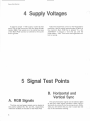
4 Supply Voltages
To test for proper + 105V supply, locate the test
point TP91 at the front end of the very large 20-watt
resistor R609. This resistor is in the center rear area
of the Main PCB. Connect a voltmeter at this point
and to ground.
Adjust the brightness control on the Neck PCB to
maximum. Use the nearby potentiometer (VR601) on
the monitor's Main PCB that is labeled "B + ADJUSTMENT" in Figure 2. Turn this pot until the
meter reads + 105V. Then return the brightness control to normal.
5 Signal Test Points
A. RGB Signals
The blue, red, and green signals can be tested at
the points labeled ED, EE, and EA, respectively.
These are located on the back of the Neck PCB.
6
B. Horizontal and
Vertical Sync
This synchronization signal can be tested at pin 5
of the 6-pin video signal connector. When using a
test prod, do not jam it into the connector pin. Otherwise you will stretch the pin, and it could later fall
out of the connector housing.
.......
.,,
0
...
:::s
::;
s:
Q
:::s
'<
0
m
CJ)
0
_.,.
3
;
cc
ar
c
~
0
()
m
.&::a
(iJ
ce·
c
100 ± 10VAC
(-
SYNC
SEPARATOR
POWER
RECTIFIER
SYNC
AMPLIFIER
VOLTAGE
REGULATOR
HORIZONTAL
OSCILLATOR
VERTICAL
OSCILLATOR
~-
~·
+105V
HORIZONTAL
DRIVE
OVERVOLTAGE
PROTECTOR
VERTICAL
DRIVE
R,G,B
INTERFACE
I
PINCUSHION
HORIZONTAL
DEFLECTION
YOKE
HORIZONTAL
OUTPUT
VERTICAL
OUTPUT
+105V
R,G,B
OUTPUT
-::-
..
I
ANODE
24.5 KV (0 ma)
+24
+175----~
VERTICAL
DEFLECTION
YOKE
°:- FOCUS
I I I
11 I
-
G2
'
I
J
•
.
..
.
.
Sanyo Color Monitor
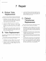
7 Repair
A. Picture Tube
Replacement
Be sure to first unplug the power and video-signal
connectors. Remove monitor assembly from game.
1.
Discharge the high voltage from the tube.
Remove the large high-voltage anode connector
near the top of the picture tube. Unplug the
neck board at rear of picture tube.
2.
Unplug the degaussing coil 2-pin connector.
3.
Unplug the 4-wire connector on Main PCB.
Unhook the spring that holds the braided
ground wire (near the bottom corner of picture
tube).
4.
Using a 5/16" hex socket wrench, remove the
four screws that hold the picture tube in the
steel frame. Carefully remove the tube by pulling it out towards the front.
3.
Loosen the Phillips screws that tighten the two
neck clamps around the neck. Now. slide the
magnet assembly, then the yoke assembly off
the end of the picture tube.
C. Flyback
Transformer
Replacement
First unplug the power and video-signal connectors. Remove monitor assembly from game.
1.
Discharge the high voltage from the tube.
Remove the large anode connector at top of picture tube. Also open the white twist-and-tie
anode holder and remove the anode wire from
this holder.
B. Yoke Replacement
2.
Unplug the neck board at rear of picture tube.
Unplug the two white wires at the very top of the
"FOCUS" adjustment bracket.
You need to reconverge the picture whenever you
replace a yoke.
3.
Remove the two small hex nuts and the Phillips
screw that secure the flyback transformer cover
plate.
First unplug the power and video-signal connectors. Remove monitor assembly from game.
4.
Unsolder the 9 connections for the transformer
on the circuit or bottom side of the Main PCB.
1.
Discharge the high voltage from the tube.
Unplug the neck board at rear of picture tube.
5.
2.
Using a thin knife or single-edged razor blade,
carefully loosen the rubber wedges from the
picture-tube surface.
Now lift out the transformer. When replacing
with a new transformer, be sure to check the
picture for sharpness. If it's not sharp, adjust
the white focus knob on the transformer.
I
\______/
8
Sanyo Color Monitor
8 Adjustments
A. Purity
Adjustments
1. Preliminary
First remove the monitor from the game, but leave
the connectors still attached. The purity and convergence magnets can be moved without loosening
the rear Phillips screw. If you will also be converging
the outer area of the picture (see Section 2 on the
next page), you should loosen both the deflection
yoke and magnet mounting screws at this time.
Turn the picture tube so it faces north or south.
Then degauss the picture tube with a hand-held
degaussing coil. If the magnets have been secured
with a white glue, you will find that its hold can be
easily broken when you move the magnets.
2. Red Purity Adjustment
Refer to Figure 3 and turn off the green and blue
guns with the G and B bias or cutoff controls, located on the neck board. (Leave the red gun on.) Display any self-test pattern on the screen that shows
solid white. Keep this display throughput the purity
adjustments.
Rotate and spread the tabs of the purity magnets
(the pair farthest towards the front) until you center
the screen image vertically and horizontally. You
should also obtain a pure red overall.
3. Green Purity Adjustment
Turn off the red and blue guns by using the controls on the neck board; leave the green gun on.
Readjust the purity magnets if necessary for a uniformly green screen.
5. Final Check
As a final check for total color purity, turn on all
guns again. Leave the all-white self-test pattern on
the screen. The screen should be pure, clean
white-not tinted with other hues.
Finally, reinstall the monitor in the game.
B. Convergence
Adjustments
1. Static Convergence (Center Area)
First remove the monitor from the game, but leave
the connectors still attached.
If you will also be converging the outer area of the
picture (see Section 2 that follows), you should
loosen both the deflection yoke and magnet mounting screws at this time.
Display the diagnostics pattern that shows black
background with white lines and dots. Keep this
display throughout all convergence adjustments.
Refer to Figure 3 and turn off the green gun with
the G bias or cutoff control, located on the neck
board. (Leave the red and blue guns on.)
Adjust the angle of the 4-pole or center pair of
magnets, and superimpose the red and blue vertical
lines in the center area of the screen.
Keeping their angles the same, rotate both tabs of
the 4-pole magnets to superimpose the red and blue
horizontal lines in the center area of the screen.
4. Blue Purity Adjustment
Turn on the green gun again. Adjust the angle of
the 6-pole or rear pair of magnets, and superimpose
the green vertical lines on the red/blue ones, in the
center area of the screen.
Turn off the red and blue guns by using the controls on the neck board; leave the blue gun on.
Repeat the purity adjustment for a uniformly blue
screen.
Finally, keeping their angles the same, rotate both
tabs of the 6-pole magnets to superimpose the
green horizontal lines on the red/blue ones.
9
Sanyo Color Monitor
FROM
r---- - - - - - -- -- -- - - ---- -- - - - - -- I
MAIN CHASSIS CIRCUIT BOARD
I
GROUND
BH'~~-----------------------------------+-~vvv---t
~
~
DRIVE
TR 204 - TR 20!0
2SC536 (E,F. G) X 3 ~-~
TR2Ql-TR203
2SC53b (F,G) X3
IP1cruRE fiJ 8E socKET BoAR D-u8854o6
I
I
I
I
I
CR208
AP
I
I
I
BUFFER
BOARD
------------------~
U885401
I
SYNC.
MAIN
lcONTROL CIRCWT- I BOARD U885383
I
I
I
L251-L253
LXXJl50
I
I
BLUE OUTPUT
~T~R~2~5~2_ _ ___..._ _--+-/\;'V'r--~
I
I
I
I
I
I
I
820
RE=O
INPUT
I
CR211
I
I
14
I
I~
2
12
3
IC201
SN74CON 4
10
5
IC
CR
212
9
I:
TR207
2SC53G (E,F,G)
I
~f
-!.:Y'
A~\
IK
CR204
___ __,
,-,- - - - --...,,
\,__
R227
I
AN .
AM
AO
I
i-1-,-=--=::I~o~ ~A_!!l_C2!::!6_sgs_c_'.3c_u~s_Q~_ 1
I
I
I
C210
.01
-::-
K
J
L901
L7571AGO
I
I
FH
L __ - - - - ---'
BHi'r· ----.
R243
2700
~FG
I
I
CR206
-::-
CR? ll -CR::'I::'..
15 1555
VR35.3
B-3K
!
8
INPUT
FROM
MAIN
CHASSIS
CIRCUIT
BOARD
I
-BH3
R242
GREEN
VR355
B-50K
I
I
8LUE.
FD
VR.352
B-30K
I
I
INPUT
(
I
E
e
_
_JAO \ . - - - .... -1
PS 601
I- - - - - I
I
PTH451C05 I
I
I
CRGOl-604 I
I
I
t:RC04-0b I
I
I
CR603 L - - - - _J
I
C602
R224
SERVICE
TIP
5f.,('I
IOOOC
IOOOP
TO C462
TP.91
IC 601
LA 5110
R409
R421
IK
HORIZ.
POSITION
33
1())
C453
I
C413
.015
R406
ISK
TP33
. ~~
4
I
I
I
I
I
I
I
C461
470P
HORIZ. DRIVE
I
I
I
-------=-~~~~~~-----------
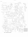
Figure 5
10
Schematic Diagram of Sanyo Monitor
150
I
I
Sr---C-4-0~7-R_4_17--------------,-,:-::----~
L_
3 I
I 2 I
I
I AC INPUT
I
_L
I
-..../
I
I
I
I
CS07
.022
R605
56K
NOTICE TO ALL PERSONS RECEIVING THIS DRAWING
CONFIDENTIAL: Reproduction forbidden without the
specific written permission of Atari, Inc., Sunnyvale .. CA.
This drawing is only conditionally issued, and neither
receipt nor possession thereof confers or transfers any
right in, or license to use, the subject matter of the draw·
ing or any design or technical information shown thereon,
nor any right to reproduce this drawing or any part
thereof. Except for manufacture by vendors of Atari, Inc ..
and for manufacture under the corporation 's writter
license, no right to reproduce this drawing is granted 01
the subject matter thereof unless by written agreement
with or written permission from the corporation.
)
Sanyo Color Monitor
If you do not need to converge the outer screen
areas, you are done with the convergence procedure. (Otherwise, immediately proceed with Section 2 below.)
Slide the yoke slightly away from the picture tube.
Up/down movement of the yoke causes the outer
edges of the screen image to swivel clockwise or
counterclockwise. Side-to-side movement causes
the lines and dots at the outer screen edges to expand and contract.
2. Dynamic Convergence (Outer
Area)
Move the yoke in the up/down and side-to-side
directions until the outer lines and dots on the
screen are pure white.
Be sure to keep the same convergence pattern on
the screen-white lines and dots with black
background. Using a razor blade or thin knife,
carefully loosen the glue holding the three rubber
wedges and remove them. Be sure both the magnet
and deflection yoke mounting screws are loosened.
Then secure the deflection yoke by putting the
wedges back in between the picture tube and the
yoke's white collar. Secure the wedges with glue.
Tighten the screws that secure the deflection yoke
clamp and the magnets.
9 Schematic and Illustrated
Parts Lists
The purpose of this chapter is to provide you with
the necessary information for ordering replacement
parts for your Sanyo 14" color monitor. Please note
that, for simplicity, common hardware and certain
other parts have been deleted from this parts list.
This includes screws, nuts, washers, certain connectors and tie wraps, in addition to metal parts,
such as heat sinks, shields and supports.
When ordering parts from your distributor, give
the part number, part name and serial number of
your game. This will help to avoid confusion and
mistakes in your order. We hope the results will be
less downtime and more profit from your game.
11
.8
·;::
0
0
~
0
()
0
<'1
>c
en
>< •
~~
0
Q)
C0
c.r:.
o~.
:;: >< Q)
cca ><
)( ...
::I
u
e>a: -;
·u; (.)
•• Q) 0 c
G>-c_
Q)
oa>-cE
c
Cl
c
ZUG>o
~ Ii Ii
a;£.~
~ i Q;
0
'C
.c c:r:
-c a> E
Q)
= > ...
:c
ca 'C
ca
c:r: .r:.
. o~
Oe610
C=OAmp.
DC.. .3Som.
TH2.0/
0
'<t
~
-
f?Zt 7
OIP
TR.2.
Of
;::
"'
N
Ct'.
-c:::J-
()(.
R2"27
OR231
TRZOI
-ll
"Z.
8
-c::J-0R475
R.472
....fR4sT1...._
-..9
;!
1"
~
"'
~
<)o
l<.172
~/(,,/
.J
:;:
~
C452
~
o-
c:::::::J
lc4S61
~
c.477
e
C457
"
.E'.4SS"
-
-----
"'l
;:\'
R47'1
Ill
-c::J-
R4"-1
f,23
-c::J-
\)
C40I
R.4ot.
-c:::JC.-£451
d <>
CJ
R4ol
c.'"'
R.401
~
_
;
m
-~ ~o P~·
~
C4o<,
~
~407
R.4"'1
R4ob
~
ij o-~
C4b3
R414
-c:::JC-4oq
c::=::::J
o~
-
~"'~
c::J c::
C.45'1
u
R4 5 I
c.!h2.
-c:::J-
Q
Cfiolo
Rlloh
C4l,,f
~
""ra@,
-c::J-
c:::>
<7
~IO~
~<Xl C451~
~G]
c "' "' ~
v,e4sz ~
~ ~ 0o-:-c::::J~TRozo7o~zs 0-Q ~·
-C:5- ;n
Ct'.y ~c4sa
ormr~ ~ 3
TT?208
" --i:::J-C.E'.2.05~
~ -c::::rQ~
CZ
::e:::::J-~n-c:::::J.8224
Ct'.
N
n
yn
yn
y~
e
c2•3
R2o2.
Rlt.4
-c:::J-R.413
~
0-c;t7'cio eo~
~ g~;o~ ~m~:,g
"<
- ~~~ ~ yyyy
tr:
"'~ MN -c::J- Om202~0
O"';;;
/O
-c:::JRZtf:,-c:::J-
TRZo5
.,___,--
-c:::J- R.
0 480
oev~-=~9
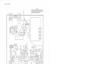
--C:JE23S:O
-c:::JRZ37
1'11..Q
c::::> R214-Dcfi.'z 0 o".!"' ~
Ct'.
<>
a11.~Q...,0
C2I 2
.,
~ ~
0
R Z33
-c:::::;-
RZ.32-c:J-
I\_ -c::J-
v
@-
VRzofUl
R471
-c::::}.z.oti455
4
R. 1!.
~
C.475 C.R454
-c::J-
..fR4i8l-c
0
0
4
~"*O. O"'"E0~t:-:1
~ .g., o~ ~i/(qO
9 n~
ltlll -c:::::r t::::r
~
0
"'>
C2o8
<t
Ql
~o ~oe474o
Ill
@~
\
>a
25
E
Q)
m
<"'"'
0
c
a..
·ca
~
CD
!
::::s
C>
u:
~
C\I
Sanyo Color Monitor
RZ.54
-c:::J-
R252
-c::J-c::JR2.fofo
Vl<Z54
V~Z55
VR251
VR252
\IR253
Figure 7
Neck PCB Assembly
13
Sanyo Color Monitor
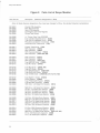
Figure 8
Atari Part No.
Description
Parts List of Sanyo Monitor
(Reference Designations in Bold)
Note: All diode reference designations Dxxx have been changed to CRxxx, the standard American nomenclature.
99-160001
99-160002
99-160003
99-160004
99-160005
Control PCB Assembly
Main PCB Assembly
Neck PCB Assembly
Convergence and Purity Magnets
Picture-Tube Socket
99-160006
99-160007
99-160008
99-160009
99-160010
14" Picture Tube, Type 370ECB22
Type LA 1464 Integrated Circuit (IC401)
Type LA5110 Integrated Circuit (IC601)
Pincushion Correction Transformer (T401)
Horizontal Drive Transformer (T451)
99-160011
99-160012
99-160013
99-160014
99-160015
Flyback Transformer (T452)
N PN Transistor (TR902)
N PN Transistor (TR901)
N PN Transistor/Damper (TR904)
NPN Transistor (TR201-203, 208)
99-160016
99-160017
99-160018
99-160100
99-160101
PNP Transistor (TR210)
NPN Transistor (TR451)
NPN Transistor (TR251-253)
Type SIB01-02 Diode (CR455)
Type RU1 Diode (CR453)
99-160102
99-160103
99-160104
99-160105
99-160106
Type
Type
Type
Type
Type
99-160107
99-160200
99-160201
99-160202
99-160203
Type EQA01-11 Diode (CR204)
Focus Resistor (VR902)
Type PTH451 C05 Posistor (PS601)
Type SDT-500 Thermistor (TH201)
100K Ohm, 1/4 W Metal-Film Resistor
99-160204
99-160205
99-160206
99-160207
99-160208
5600 Ohm, 1/4 W Metal-Film Resistor (R608)
33 Ohm, V2W Metal-Film Resistor (R409)
3.9 Ohm, 1W Metal-Film Resistor (R481)
390 Ohm, 2W Metal-Film Resistor (R474)
560 Ohm, 1W Metal-Oxide Resistor (R244)
99-160209
99-160210
99-160211
99-160212
99-160213
10K Ohm, 2W Metal-Oxide Resistor (R463)
6800 Ohm, 2W Metal-Oxide Resistor (R418)
1200 Ohm, 3W Metal-Oxide Resistor (R604)
3300 Ohm, 3W Metal-Oxide Resistor (R466)
180 Ohm, 20W Wirewound Resistor (R609)
99-160214
99-160215
99-160216
99-160300
99-160301
2.0 Ohm, 20W Wirewound Resistor (R601)
1.0 Ohm, 1W Metal-Oxide Resistor (R273)
5600 Ohm, 1W Metal-Oxide Resistor (R253, 257, 261)
470 uf, 10V Electrolytic Capacitor (C609)
10 uf, 16V Electrolytic Capacitor (C479)
14
RU2 Diode (CR454, 456)
RC2 Diode (CR452)
ERC04-06 Diode (CR601-604)
EQA01-05S Diode (CR451)
1S1555 Diode (CR205-209, 211-213, 401, 402)
(R610)
Sanyo Color Monitor
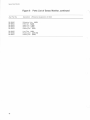
Figure 8
J
Parts List of Sanyo Monitor, continued
Atari Part No.
Description
(Reference Designations in Bold)
99-160302
99-160303
99-160304
99-160305
99-160306
100 uf, 16V Electrolytic Capacitor (C211)
220 uf, 16V Electrolytic Capacitor (C161, 202)
47 uf, 16V Electrolytic Capacitor (C208)
330 uf, 25V Electrolytic Capacitor (C484)
4.7 uf, 25V Electrolytic Capacitor (C162, 206, 408)
99-160307
99-160308
99-160309
99-160310
99-160311
1.0 uf, 50V Electrolytic Capacitor (C166, 207, 453, 455, 458)
100 uf, 25V Electrolytic Capacitor (C457, 610)
10 uf, 160V Electrolytic Capacitor (C471)
100 uf, 160V Electrolytic Capacitor (C462)
4.7 uf, 160V Electrolytic Capacitor (C406)
99-160312
99-160313
99-160314
99-160315
99-160316
47 uf, 160V Electrolytic Capacitor (C410)
Type 160EE4719C Electrolytic Capacitor (C606)
0.01 uf, 50V Ceramic Capacitor (C203, 204, 210, 212, 452)
0.022 uf, 50V Ceramic Capacitor (C207)
0.015 uf, 50V Mylar Capacitor (C402, 404, 413)
99-160317
99-160318
99-160319
99-160320
99-160321
8200 pf, 50V Mylar Capacitor (C451, 459)
2700 pf, 50V Mylar Capacitor (C477)
0.047 mf, 100V Mylar Capacitor (C483)
0.068 mf, 50V Mylar Capacitor (C405)
820 pf, 50V Ceramic Capacitor (C463)
99-160322
99-160323
99-160324
99-160325
99-160326
470 pf, 500V Ceramic Capacitor (C461)
4700 pf, 500V Ceramic Capacitor (C486)
820 pf, 500V Ceramic Capacitor (C470, 473)
1000 pf, 1000V Ceramic Capacitor (C602-605)
1500 pf, 2000V Ceramic Capacitor (C465, 466, 468, 481, 482, 485)
99-160327
99-160328
99-160329
99-160330
99-160331
500 pf, 2000V Ceramic Capacitor (C467)
0.082 mf, 50V Mylar Capacitor (C403)
0.33 mf, 50V Mylar Capacitor (C407)
0.056 mf, 125V Mylar Capacitor (C601)
0.1 mf, 1000V Mylar Capacitor (C469)
99-160332
99-160333
99-160334
99-160335
99-160336
0.068 mf, 50V Mylar Capacitor (C401)
0.47 mf, 400V Polypropylene Capacitor (C412)
2700 pf, 630V Polypropylene Capacitor (C456)
1000 pf, 2000V Ceramic Capacitor (C901)
100 pf, 50V Ceramic Capacitor (C251-253)
99-160337
99-160400
99-160401
99-160402
99-160403
1000
Type
Type
Type
Type
pf, 1000V Ceramic Capacitor (C257, 258)
8C1 FR5B 3K-Ohm Variable Resistor (VR353)
8C1 FR5B 200K-Ohm Variable Resistor (VR354)
8C1 FR5B 50K-Ohm Variable Resistor (VR352, 355)
8C1 FR5B 10K-Ohm Variable Resistor (VR251-253)
99-160404
99-160405
99-160406
99-160407
99-160408
Type
Type
Type
Type
Type
8C1 FR5B 200-0hm Variable Resistor (VR254, 255)
15CFR1 OB 1M-Ohm Variable Resistor (VR256)
8L2FRB 5K-Ohm Variable Resistor (VR601)
8LFRB 20K-Ohm Variable Resistor (VR201)
8CFRB 500K-Ohm Variable Resistor (VR452)
15
Sanyo Color Monitor
Figure 8
Parts List of Sanyo Monitor, continued
Atari Part No.
Description
99-160450
99-160451
99-160452
99-160453
99-160454
Deflection Yoke (L902)
Filter Coil (L452)
Width Coil (T454)
Width Coil (T455)
Peaking Coil (L451)
99-160455
99-160456
99-160457
Line Filter (L601)
Peaking Coil (L251·253)
Peaking Coil (L254)
16
(Reference Designations in Bold)
14" Sanyo Monitor
1st printing
YOUR COMMENTS, PLEASE!
Your comments will assist Atari in improving the usefulness of our publications.
They are an important part of preparing for revisions of manuals and parts
catalogs. No postage stamp is necessary if mailed in the U.S.A.
If you have any technical questions about certain Atari or Kee Games products, or
are requesting additional publications, we will immediately forward your note to
the appropriate person.
Page:
Comments:
J
Fill in if you wish a reply:
Name _ _ _ _ _ _ _ _ __
Firm _ _ _ _ _ _ _ _ __
D Distributor
Address _ _ _ _ _ _ _ _ _ _ _ _ _ _ _ _ _ _ _ _ __
D Operator
City _ _ _ _ _ _ __
D Other _ _ _ _ _ _ __
State _ _ _ _ _ _ __
Zip _ __
First fold
---------------------------------
11111
No Postage
Necessary
if mailed in
the United States
,'
I
I
1
I
t
BUSINESS REPLY MAIL
FIRST CLASS
PERM IT NO. 1004
SUNNYVALE, CA
I
POSTAGE WILL BE PAID BY ADDRESSEE
I~
I~
Atari, Inc.
Attn.: Field Service/Coin-Op Division
P. 0. Box 427
Sunnyvale, California 94086
I~
18
I
I
I
I
- - - - - - - - - - - - - - ___
· -----------1
Second fold
:WOJ.::J
a6pe S!4l ede1
G>
-
I
I
I
I
I
I
I
I
I
I
I
I
I
I
I
I
I
I
I
'- --......
Cl
ATARI INC
A Warner Communicallons Company
1265 BORREGAS AVENUE, P. 0. BOX 427, SUNNYVALE, CALIF. 94086
-408/745-2000