1
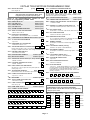
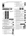
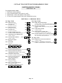
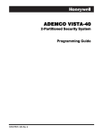
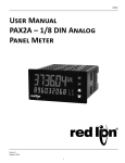
Previous Menu
VISTA-40
2-Partition
Security System
Programming Guide
Single Partition and 2-Partition
Programming Forms
®
N7001PRV4 7/98
TABLE OF CONTENTS
SINGLE PARTITION PROGRAMMING FORM................................................................................3
TWO-PARTITION PROGRAMMING FORM.....................................................................................7
SYSTEM-WIDE DATA FIELDS..........................................................................................................8
PARTITION-SPECIFIC DATA FIELDS .............................................................................................11
PROGRAMMING WITH #93 MENU MODE (Overview))..............................................................13
CHANGING ZONE RESPONSE TYPE & REPORT CODES (EXPERT MODE) .......................14
SYSTEM LAYOUT WORKSHEETS ..............................................................................................16
Other Documents Provided With The VISTA-40
Document
Installation
Instructions
User’s Manual
Purpose and Content
Use the Installation Instructions portion of this manual when installing the hard-ware
components of the installation, including hardwired zones, wireless transmitters,
powering the control, etc. Use the Programming Procedures section of the
installation manual when programming the system. It provides detailed programming
procedures and descriptions of all data fields. It also provides detailed procedures for
using #93 Menu Mode.
A Summary Of Connections Diagram is provided at the back of the Installation
Instructions.
Intended for the end user, this manual provides procedures for system operation.
This Programming Guide includes basic programming information, a brief overview of the
programming procedure with #93 Menu Mode, Changing Response type & Report Codes (Expert
Mode), Single and 2-Partition Programming Forms, plus System Layout Worksheets.
Two programming forms are provided: A Single Partition Form and a 2-Partition Form.
• Make sure that one alpha or voice/alpha keypad is connected to the control and is set to device address
"00."
Single Partition System
• The system default is for a single partition system. Use the SINGLE PARTITION PROGRAMMING FORM
beginning on page 4 when programming for single partition usage.
Two-Partition System
• You must enter "2" in data field 2✱ 00 to set the system for two partitions. Use the 2-PARTITION
PROGRAMMING FORM beginning on page 8 when programming the system for two partitions.
# 93 Menu Mode
• Because the control supports various types of input devices (such as button type transmitters, serial
number polling loop devices, etc.), zone characteristics, including zone response types and report codes,
must be programmed using the #93 Menu Mode procedure.
• In addition to programming zone information, #93 Menu Mode is required for enrolling serial numbers,
programming alpha descriptors, programming device characteristics and for programming relay output
functions.
• Refer to the separate Installation and Setup Guide for detailed procedures when using #93 Menu Mode.
Page 2
VISTA-40 SINGLE PARTITION PROGRAMMING FORM
Use the Single Partition Programming Form only if your system is set up as a single
partition system.
For 2-partition systems, use the form titled "VISTA-40 Two-Partition Programming Form."
Steps To Programming a Single Partition VISTA-40 System
IMPORTANT: A 2-Line Alpha keypad is required for programming the VISTA-40.
Make sure that one alpha keypad is connected to the control and is set to device address "00."
1. Enter Programming Mode (enter installer code + [8] + [0] + [0]).
2. Program the data fields shown on the programming form.
NOTE: Zone Response Type and Report Code fields will automatically appear during normal
programming, but must be skipped if the zone has not been previously programmed using #93 Menu
Mode (see step 3 below). These fields are bordered by a dotted line on the programming forms and
include:
✱02 - ✱05 and 1✱01 - 1✱09 ASSIGN RESPONSE TYPES
✱54 - ✱78 REPORT CODES
To skip these fields when they appear, press [✱] plus the next data field number to be programmed. For
example, to skip fields ✱02 - ✱05 in a one partition system, press [✱] plus "09." Field ✱09 ENTRY DELAY
#1 appears.
3. Enter #93 Menu Mode by pressing #93 while in programming mode, then do the following in the order
presented:
• Use the DEVICE PROG. prompts to program device addresses and characteristics.
• Use the ZONE PROG. prompts to program zone information.
• Use the RELAY PROG. prompts to program relay output information.
• Use the ALPHA PROG. prompts to program alpha descriptors.
• Use the SERIAL # PROG prompts to program sensor device serial numbers.
• Use RLY VOICE DESCR. prompts to program relay voice descriptors, if the 4285 Phone Module is
used.
• Use the CUSTOM INDEX prompts to program custom word substitutes, if the 4285 Phone Module is
used.
Refer to the #93 Menu Mode section of the separate INSTALLATION INSTRUCTIONS document for
detailed procedures when using #93 Menu Mode. A brief overview of this mode is provided later in this
document.
SUMMARY OF PROGRAMMING COMMANDS
• To enter program mode, enter installer code + [8] + [0] + [0]
• To set standard defaults, press ✱ 9 7
• To set communication defaults, press ✱ 94 + one of the following: ✱ 80=low speed; ✱ 81=Ademco
Express; ✱82=Ademco High Speed; ✱83=Ademco's Contact ID
• To change to next page of program fields, press ✱ 9 4
• To return to previous set of fields, press ✱ 9 9
• To erase account & phone number field entries, press [✱ ] + field number + [✱ ]
• To assign zone descriptors, press #93 + follow menu prompts
• To add custom words, press #93 + follow menu prompts
• To enter Installer's Message, press #93 + follow menu prompts
• To exit program mode, press ✱99 OR ✱98: ✱99 allows re-access to programming mode by installer code.
✱98 prevents re-access to programming mode by installer code.
Page 3
VISTA-40 SINGLE PARTITION PROGRAMMING FORM
Standard default (✱97) values are shown in brackets [ ], otherwise default = 0.
✱ 00
|
✱ 33
ASSIGN RESPONSE TYPE FOR ZONES
Skip these fields. Use #93 Menu Mode, Zone
Programming to program response types.
✱ 34
SECONDARY PHONE NUMBER
✱ 35
DOWNLOAD PHONE No.
INSTALLER CODE
[4140]
|
|
PRIMARY PHONE NUMBER
Enter 4 digits, 0-9
✱02
✱0 9
- ✱05
ENTRY DELAY #1
[02]
|
[03]
|
Enter 0-9 for each digit, or #11 (✴), #12 (#), #13 (pause)
Enter 0-9 for each digit, or #11 (✴), #12 (#), #13 (pause)
(00-15 times 15 seconds)
✱1 0
EXIT DELAY #1
Enter 0-9 for each digit, or #11 (✴), #12 (#), #13 (pause)
(00-15 times 15 seconds)
✱1 1
ENTRY DELAY #2
[06]
✱3 6
DOWNLOAD ID No.
|
|
|
|
|
(00-15 times 15 seconds)
|
|
|
|
Enter 00-09; A-F (10-15) [15 15 15 15 15 15 15 15]
✱1 2
EXIT DELAY #2
[08]
|
✱ 37
[04]
|
ZONE 9 FAST/SLOW RESPONSE
Dialer System
Not
Remote Remote Remote Upload Download
Shutdwn Shutdwn Used Bypass Disarm Arm
Program Program
See field 1✱ 53 for Callback disable option; [1=enable]; 0=disable; For UL
installations, all options must be disabled.
1=fast; 0= slow; "0" for UL.
✱3 8
(00-15 times 15 seconds)
✱1 3
ALARM SOUNDER DURATION
01-15 times 2 minutes . Minimum 4 minutes for UL.
✱1 4
✱1 5
KEYSWITCH ASSIGNMENT
✱3 9
✱2 1
✱4 0
OPEN/CLOSE REPORTING FOR KEYSWITCH
✱ 41
NORMALLY CLOSED or EOLR (Zones 2-8)
RANDOMIZE AC LOSS REPORT
✱ 42
4285 PHONE MODULE ACCESS CODE
|
Enter 01-09 for 1st digit; 11( for ✴) or 12 (for #) for
2nd digit To disable voice module, enter
1st digit = 00 & 2nd digit = 11
[00]
[11]
✱ 43
[1]
✱ 44
RING DETECTION COUNT
|
01-14; 15=answering machine; 00=no detection; Do not set to 00 if
voice module is used, or 01 if VIM module is used.
[0-0-1]
1=enable; 0=disable
✱2 3
DIAL TONE DETECTION
1=wait for true dial tone; 0=pause, then dial
PREVENT FIRE TIME-OUT
KEYPAD PANIC ENABLES
DIAL TONE PAUSE
0=5 seconds; 1=11 seconds; 2=30 seconds; Must be "0" for UL.
|
1=no timeout; 0=fire timeout
✱2 2
[1]
1=N.C.loops; 0=EOLR supervision; Must be "0" for UL.
1=randomize 10-40 min.; 0=no
✱2 0
OPEN/CLOSE REPORT FOR INSTALLER
1=enable; 0=disable
AC LOSS KEYPAD SOUNDING
1=yes; 0=no
✱1 9
|
1=enable; 0=disable
CONFIRMATION OF ARMING DING
1=enable; 0=disable
✱1 7
PREVENT ZONE XX BYPASS
01-64; 00 if all zones (except Fire zones) can be bypassed
Enter partition in which keyswitch used, 1-2; 0=disable
✱1 6
DOWNLOAD COMMAND ENABLES
0
✱ 45
95
MULTIPLE ALARMS
96 99
[1]
1=yes; 0=no
PRIMARY FORMAT
0=Low Speed; 1=Contact ID; 2=Ademco High Speed;
3=Ademco Express
✱ 46
LOW SPEED FORMAT (Primary)
0=Ademco Low Speed; 1=Sescoa/Radionics
✱2 4
IGNORE EXPANSION ZONE (RF, RPM) TAMPER
✱ 47
1=disable; 0=enable
✱2 5
LRR BURG.TRIGGER FOR TYPE 8
0=Low Speed; 1=Contact ID; 2=Ademco High Speed;
3=Ademco Express
[1]
✱ 48
1=enable; 0=disable
✱2 6
INTELLIGENT TEST REPORTING
TEST REPORT INTERVAL
[024]
|
POWER UP IN PREVIOUS STATE
[1]
QUICK ARM
CHECKSUM VERIFICATION
✱ 50
SESCOA/RADIONICS SELECT
TOUCH-TONE OR ROTARY DIAL
1=TouchTone; 0=rotary
✱3 1
✱ 52
PABX ACCESS CODE
|
|
|
Alarm Rstr Bypass Trbl Opn/Cls Low Bat
0=standard; 1=expanded; Note: Expanded overrides 4+2 format.
PRIM. SUBS. ACCT #
Enter 00-09; B-F (11-15)
STANDARD/EXPANDED REPORT FOR PRIMARY
|
00-09; B-F (11-15)
✱3 2
DUAL REPORTING
1=yes; 0=no; If used with Spilt Reporting "1" option (1✱ 34), alarms
go to both primary & secondary numbers, while all other reports go
to secondary only. If used with Split Reporting "2" option,
open/close and test messages go to both lines, while all other
reports go to primary.
[1]
1=yes; 0=no
✱ 30
1=yes; 0=no
1=Sescoa; 0=Radionics
✱ 51
1=yes; 0=no; "1" for UL.
✱2 9
✱ 49
Prim Scndry
|
Enter interval in hours, 001-199; 000=no report ; Max. 024 for UL.
✱ 28
LOW SPEED FORMAT (Sec.)
0=Ademco Low Speed; 1=Sescoa/Radionics
Set "0" for UL 1=yes, (no report sent if any other report was
recently sent); 0=no
✱2 7
SECONDARY FORMAT
|
[15 15 15 15]
|
|
|
✱ 53
STANDARD/EXPANDED REPORT FOR SECONDARY
Alarm Rstr Bypass Trbl Opn/Cls Low Bat
0=Standard; 1=Expanded; Note: Expanded Overrides 4+2 Format.
Page 4
VISTA-40 SINGLE PARTITION PROGRAMMING FORM
✱54 -✱57
✱58
ALARM REPORT CODE & ID DIGITS FOR ZONES
1-16. Skip these fields. Use #93 Menu Mode,
Zone Programming to assign report codes.
SUPV. & RESTORE CODES for zones 1-16
|
Alarm Rst.
|
Trouble
|
Trble Rst.
|
Bypass
|
Bypass Rst.
✱59 -✱62
✱63
Open
|
|
Low Battery
|
|
Low Bat Res
|
|
AC Loss
|
|
AC Restore
|
|
Test
|
|
Power
|
|
Cancel
|
|
Prog. Tamp.
|
|
ALARM REPORT CODE & ID DIGITS FOR ZONES
17-32. Skip these fields. Use #93 Menu Mode,
Zone Programming to assign report codes.
SUPV. & RESTORE CODES for zones 17-32
|
Alarm Rst.
|
Trouble
|
Trble Rst.
|
Bypass
|
Bypass Rst.
✱64
SYSTEM NON ALARM CODES
✱8 1
✱8 2
First Digit Second Digit
Close
|
|
✱8 3
Second digit of each
code applies only to
4+2 or expanded (fields
✱52 & ✱53) formats.
FIRST TEST REPORT TIME
|
|
|
[Day 00; hour 12; min 00] Days 01-07 Hours 00-23 Min 00-59;
00 in all boxes=instant (Day 01= Monday)
✱8 4
SWINGER SUPPRESSION
[03]
|
01-15 alarms ; Must be "00" (disabled) for UL.
✱8 5
ENABLE DIALER REPORTS
FOR PANICS & DURESS
95
96
99
Duress
1=enable; 0=disable
- ✱67 ALARM REPORT CODE & ID DIGITS FOR ZONES
33-48. Skip these fields. Use #93 Menu Mode,
Zone Programming to assign report codes.
✱ 86
4208 MODULE ZONE ASSIGNMENT
1=allows 8 zone numbers (10-17) on one module, but prevents any
other polling loop expansion; 0=Otherwise
✱8 7
ENTRY WARNING
[1]
1=continuous; 0=3 beeps
✱68
SUPV. & RESTORE CODES for zones 33-48
|
✱8 8
BURG. ALARM COMM. DELAY
✱8 9
RESTORE REPORT TIMING
✱9 0
2nd SUBS. ACCT #
Alarm Rst.
1=16 seconds; 0=no delay
|
Trouble
|
Trble Rst.
|
Bypass
|
Bypass Rst.
0=instant; 1=at bell timeout; 2=at disarm
Enter 00-09; B-F (11-15)
|
✱ 74-✱ 77
ALARM REPORT CODE & ID DIGITS FOR ZONES
49-99. Skip these fields. Use #93 Menu Mode,
Zone Programming to assign report codes.
Trouble
|
Trouble
|
Trble Rst.
|
Trble Rst.
|
Bypass
|
Bypass
|
Bypass Rst.
|
Bypass Rst.
1=immediate; 0=when disarmed; Must be "1" for UL
1 ✱ 2 9 RF TX LOW BATTERY REPORT ENABLE
1✱3 0
RF RCVR CHECK-IN INTERVAL
1 ✱ 3 1 RF TRANSMITTER CHECK-IN INTERVAL[12]
02-15 times 2 hours; 00 disables transmitter supervision
Max. "6" (12 hr) for UL
1 ✱ 3 2 RF RECEIVER TYPE
1=4281 ; 2=5881; 0=NONE
1 ✱ 3 3 TOUCH-TONE W/ROTARY BACKUP ENABLE
1=enable; 0=disable
4
5
6
7
8
[06]
|
02-15 times 2 hours; 00 disables supervision
Max. "6" (12 hr) for UL
ZONE TYPE RESTORE ENABLES 1=enable; [0=disable]
✱ 7 9 FOR ZONE TYPES 1-8
✱80 ZONE TYPES 9/10
3
✱94)
1✱01 - 1✱09 ASSIGN RESPONSE TYPE FOR ZONES
Skip these fields. Use #93 Menu Mode, Zone
Programming to assign response types
1=enable; 0=disable Must be "1" for UL
|
2
|
1 ✱ 2 8 RF TX LOW BATTERY SOUND
SUPV. & RESTORE CODES
✱ 73 (for zones 49-64)
✱ 78 (for zones 87-99)
|
Alarm Rst.
|
Alarm Rst.
1
|
2nd Page Programming Fields
(press
✱ 69 -✱ 72,
|
[15 15 15 15]
9
10
Page 5
|
VISTA-40 SINGLE PARTITION PROGRAMMING FORM
1 ✱ 3 4 COMM. SPLIT REPORT SELECTION
1 ✱ 7 0 EVENT LOG TYPES
0=no; 1=alarms primary, others secondary;
2=open/close, test secondary, others primary; See ✱ 51 for notes.
DIALER CODES ( Armed Stay, Time Set & Event Logging)
1✱4 0
1✱4 1
First Digit Second Digit
Armed STAY
|
|
Time/Date set or event log reset
|
1=enable logging; 0=disable
O/C Systm
0=12 hour; 1=24 hour
1✱7 4
RELAY TIMEOUT XX MINUTES
|
|
Enter the relay timeout, 0-127 in multiples of 2 minutes, desired
for #93 Menu Mode Relay Programming output command "56".
1 ✱ 7 5 RELAY TIMEOUT YY SECONDS
|
|
|
Enter the relay timeout, 0-127 seconds, desired for #93 Menu
Mode Relay Programming command "57".
1 ✱ 7 6 ACCESS CONTROL RELAY FOR PARTITION
1=enable; 0=disable; When disabled, display lights when any
key is pressed, and turns off after period of keypad inactivity.
|
Enter relay number that will be pulsed for 2 seconds whenever
code + [0] is pressed. Enter 00-08 [00]=none
1=enable; 0=disable
3rd Page Programming Fields
1 ✱ 4 5 EXIT DELAY SOUNDING
(press
1=enable; 0=disable Produces quick beeping during exit delay if
enabled.
1 ✱ 4 6 AUXILIARY OUTPUT MODE
✱94)
PARTITIONING SETUP FIELDS
2 ✱ 0 0 NUMBER OF PARTITIONS
0=ground start; 1=open/close trigger; 2=keypad sounding;
3=Non-Ademco AAV unit trigger
[1]
Enter 1 for single partition systems.
2 ✱ 0 1 DAYLIGHT SAVINGS TIME [04, 10]
|
START/END MONTH
Start
1 ✱ 4 7 CHIME ON EXT SIREN
1=enable; 0=disable
|
End
00-12; if no daylight savings time, enter 00,00
1 ✱ 4 8 WIRELESS KEYPAD ASSIGNMENT
2✱0 2
0=disable; enter partition in which RF keypad used, 1-2.
1 ✱ 4 9 SUPPRESS TX SUPERVISION SOUND
Chck Byps
1 ✱ 7 1 12/24 HOUR TIME STAMP FORMAT
1 ✱ 4 3 PERM. KEYPAD BACKLIGHT
1 ✱ 4 4 WIRELESS KEYPAD
TAMPER DETECT ENABLE
Alrm
[1]
1 ✱ 5 2 SEND CANCEL IF ALARM + OFF
|
Start | End
2 ✱ 1 7 NUMBER OF CODES PER PARTITION [69] 1
|
[01] 2
|
1=no restriction; 0=within Bell Timeout period only
Enter 01-69. Total must be less than or equal to 70.
1 ✱ 5 3 DOWNLOAD CALLBACK
1=callback not required; 0=callback required; Must be "0" for UL.
2 ✱ 1 8 ENABLE GOTO FOR THIS PARTITION
1=enable; 0=disable
1 ✱ 5 7 ENABLE 5800 RF BUTTON GLOBAL ARM
Enter "1" to have the system arm/disarm following the button's
user's global arm settings. Enter "0" if the button is not to be used
to global arm the system.
If zone is faulted after pressing button, keypad will beep once.
User should press button again within 4 sec. to force bypass
those zones. Enter 1 if force bypass is desired. Enter 0 if not
desired.
[1, 5]
Enter 1-7. 1=first; 2=second; 3=third; 4=fourth; 5=last; 6=next to
last; 7=3rd from last [default is 1st Sunday in April, last in Oct.]
1=disable; 0=enable.
Must be "0" for UL.
1 ✱ 5 8 ENABLE 5800 RF BUTTON FORCE BYPASS
DAYLIGHT SAVINGS TIME
START/END WEEKEND #
2 ✱ 1 9 USE PARTITION DESCRIPTORS
0=disable; 1=enable
2 ✱ 2 0 ENABLE J7 TRIGGERS by PARTITION
[1]
0=disable for displayed partition; 1=enable for displayed partition
2 ✱ 2 1 ENABLE SUPERVISION PULSES FOR LRR
TRIGGER OUTPUTS
| |
1 ✱ 6 0 AAV MODULE SELECT
Used for supervised connection to 7920SE.
Enter 0 to disable or 1 to enable the listed outputs.
F= Fire; B= Burglary; S= Silent panic/duress
Enter “1” only if AAV unit is used.
NOTE: If enabled zone 5 can no longer be used as a protection
zone.
1 ✱ 6 6 SILENCE BELLS DURING AAV
0 = alarm sounders continue during AAV sessions;
1 = alarm sounders silent during AAV sessions, resume after
AAV session (unless timeout has occurred).
Must be "0" for UL.
Page 6
F
B
S
VISTA-40 TWO-PARTITION PROGRAMMING FORM
Use the Two-Partition Programming Form if your system is set up for two partitions.
For single partition systems, use the form titled "VISTA-40 Single Programming Form."
IMPORTANT: A 2-Line Alpha keypad is required for programming the VISTA-40.
Make sure that one alpha keypad is connected to the control and is set to device address "00."
1. Enter Programming Mode (enter installer code + [8] + [0] + [0]).
2. Go to field 2✱00 and enter "2" to set the system for two partitions.
When set for two partitions, there are some data fields that are system-wide (global) and some that are
"partition-specific." The partition-specific fields, shown shaded on the form, can be assigned different
values for each partition, and these fields are automatically skipped when programming system-wide
fields. To program partition-specific fields, see step 4 below.
3. Program the system-wide (global) data fields shown on the main portion of the programming form. These
include all fields except those shown shaded and Zone Response Type and Report Code fields, which
require using #93 Menu Mode to program (see step 5 below).
NOTE: zone response Type and Report Code fields will automatically appear during normal
programming, but must be skipped if the zone has not been previously programmed using #93 Menu
Mode (see step 5 below). These fields are bordered by a dotted line on the programming forms and
✱02–✱05 and 1✱01–1✱09 ASSIGN RESPONSE TYPES
include:
✱54–✱78 REPORT CODES
To skip these fields when they appear, press [✱] plus the next data field number to be programmed. For
example, to skip fields ✱02–✱05, press [✱] plus "14." Field ✱14 ZONE 9 FAST/SLOW RESPONSE
appears.
4. Program the partition-specific data fields by pressing ✱91 and entering the partition number you wish to
program. The first partition-specific field (✱09 ENTRY DELAY #1) for that partition automatically appears.
Refer to the Partition-Specific section of this programming form when programming these fields for each
partition.
5. Enter #93 Menu Mode by pressing #93 while in programming mode, then do the following in the order
presented:
• Use the DEVICE PROG. prompts to program device addresses and characteristics.
• Use the ZONE PROG. prompts to program zone information.
• Use the RELAY PROG. prompts to program relay output information.
• Use the ALPHA PROG. prompts to program alpha descriptors.
• Use the SERIAL # PROG prompts to program sensor device serial numbers.
• Use RLY VOICE DESCR. prompts to program relay voice descriptors, if the 4285 Phone Module is
used.
• Use the CUSTOM INDEX prompts to program custom word substitutes, if the 4285 Phone Module is
used.
Refer to the #93 Menu Mode section of the separate INSTALLATION INSTRUCTIONS document for
detailed procedures when using #93 Menu Mode. A brief overview of this mode is provided later in this
document.
SUMMARY OF PROGRAMMING COMMANDS
• To enter program mode, enter installer code + [8] + [0] + [0]
• To set standard defaults, press ✱ 9 7
• To set communication defaults, press ✱ 94 + one of the following: ✱ 80=low speed; ✱ 81=Ademco Express;
✱82=Ademco High Speed; ✱83=Ademco's Contact ID
• To change to next page of program fields, press ✱ 9 4
• To return to previous set of fields, press ✱ 9 9
• To erase account & phone number field entries, press [✱ ] + field number + [✱ ]
• To assign zone descriptors, press #93 + follow menu prompts
• To add custom words, press #93 + follow menu prompts
• To enter Installer's Message, press #93 + follow menu prompts
• To exit program mode, press ✱99 OR ✱98: ✱99 allows re-access to programming mode by installer code.
✱98 prevents re-access to programming mode by installer code.
Standard default (✱97) values are shown in brackets [ ], otherwise default = 0.
Page 7
VISTA-40 TWO-PARTITION PROGRAMMING FORM
✱0 0
INSTALLER CODE
[4140]
|
|
✱3 7
|
Enter 4 digits, 0-9
✱02
- ✱05
Dialer System
Not
Remote Remote Remote Upload Download
Shutdwn Shutdwn Used Bypass Disarm Arm
Program Program
See field 1✱ 53 for Callback disable option; [1=enable]; 0=disable; For UL
installations, all options must be disabled.
ASSIGN RESPONSE TYPE FOR ZONES
Skip these fields. Use #93 Menu Mode, Zone
Programming to program response types.
Refer to the Partition-Specific section of this
form for programming shaded fields.
✱ 0 9 ENTRY DELAY #1
Partition-Specific
✱ 1 0 EXIT DELAY #1
Partition-Specific
✱ 1 1 ENTRY DELAY #2
Partition-Specific
✱ 1 2 EXIT DELAY #2
Partition-Specific
✱ 1 3 ALARM SOUNDER DURATION
Partition-Specific
✱1 4
✱3 8
✱3 9
PREVENT ZONE XX BYPASS
OPEN/CLOSE FOR INSTALLER
✱4 0
OPEN/CLOSE REPORTING FOR KEYSWITCH
✱4 1
KEYSWITCH ASSIGNMENT
✱ 16
CONFIRMATION OF ARMING DING Partition-Specific
✱1 7
AC LOSS KEYPAD SOUNDING
✱1 9
RANDOMIZE AC LOSS REPORT
✱2 0
4285 PHONE MODULE ACCESS CODE
1=yes; 0=no
✱4 2
DIAL TONE PAUSE
✱4 3
DIAL TONE DETECTION
✱4 4
✱ 45
|
✱4 6
|
|
PRIMARY FORMAT
LOW SPEED FORMAT (Primary)
0=Ademco Low Speed; 1=Sescoa/Radionics
SECONDARY FORMAT
0=Low Speed; 1=Contact ID; 2=Ademco High Speed; 3=Ademco
Express
PREVENT FIRE TIME-OUT
1=no timeout; 0=fire timeout
✱2 2
KEYPAD PANIC ENABLES
✱ 2 3 MULTIPLE ALARMS
Partition-Specific
Partition-Specific
IGNORE EXPANSION ZONE (RF, RPM) TAMPER
LRR BURG.TRIGGER FOR TYPE 8
✱4 8
LOW SPEED FORMAT (Sec.)
✱4 9
CHECKSUM VERIFICATION
✱5 0
SESCOA/RADIONICS SELECT
✱5 1
DUAL REPORTING
0=Ademco Low Speed; 1=Sescoa/Radionics
1=yes; 0=no
1=disable; 0=enable
[1]
INTELLIGENT TEST REPORTING
[024]
|
|
Enter interval in hours, 001-199; 000=no report ; Max. 024 for UL.
POWER UP IN PREVIOUS STATE
✱5 2
QUICK ARM
✱3 0
TOUCH-TONE OR ROTARY DIAL
✱3 1
PABX ACCESS CODE
STANDARD/EXPANDED REPORT FOR PRIMARY
[1]
1=yes; 0=no; "1" for UL.
✱ 29
Scndry
1=yes; 0=no; If used with Spilt Reporting "1" option (1✱ 34), alarms
go to both primary & secondary numbers, while all other reports go
to secondary only. If used with Split Reporting "2" option,
open/close and test messages go to both lines, while all other
reports go to primary.
Set "0" for UL 1=yes, (no report sent if any other report was
recently sent); 0=no
TEST REPORT INTERVAL
Prim
1=Sescoa; 0=Radionics
1=enable; 0=disable
✱2 8
RING DETECTION COUNT
0=Low Speed; 1=Contact ID; 2=Ademco High Speed; 3=Ademco
Express
Enter 01-09 for 1st digit; 11( for ✴) or 12 (for #) for [00]
[11]
2nd digit To disable voice module, enter 1st digit = 00 & 2nd digit = 11 ✱ 4 7
✱2 7
[1]
01-14; 15=answering machine; 00=no detection; Do not set to “00”
if voice module is used, or “01” if VIM is used.
1=randomize 10-40 min.; 0=no
✱2 6
[1]
1=N.C.loops; 0=EOLR supervision; Must be "0" for UL.
1=wait for true dial tone; 0=pause, then dial
Enter partition in which keyswitch used, 1-2; 0=disable
✱2 5
NORMALLY CLOSED or EOLR (Zones 2-8)
0=5 seconds; 1=11 seconds; 2=30 seconds; Must be "0" for UL.
✱1 5
✱2 4
Partition-Specific
Partition-Specific
1=enable; 0=disable
ZONE 9 FAST/SLOW RESPONSE
1=fast; 0= slow; "0" for UL.
✱2 1
DOWNLOAD COMMAND ENABLES
0
Alarm Rstr Bypass Trbl Opn/Cls Low Bat
0=standard; 1=expanded; Note: Expanded overrides 4+2 format.
Partition-Specific
✱5 3
STANDARD/EXPANDED REPORT FOR SECONDARY
1=TouchTone; 0=rotary
|
|
|
Alarm Rstr Bypass Trbl Opn/Cls Low Bat
0=standard; 1=expanded; Note: Expanded overrides 4+2 format.
|
00-09; B-F (11-15)
✱3 2
PRIM. SUBS. ACCT #
✱ 3 3 PRIMARY PHONE NUMBER
Partition-Specific
Enter 0-9 for each digit, or #11 (✴), #12 (#), #13 (pause)
✱3 4
✱ 5 4 - ✱ 57, ✱ 5 9 - ✱ 62, ✱ 6 4 - ✱ 67, ✱ 6 9 - ✱ 72, ✱ 7 4 - ✱ 7 7
ALARM REPORT CODE & ID DIGITS FOR ZONES
Skip these fields. Use #93 Menu Mode, Zone Programming
to assign report codes.
SUPV. & RESTORE CODES
✱58 (zones 1-16) ✱63 (zones 17-32)
|
Alrm Rst.
|
Alrm Rst.
SECONDARY PHONE NUMBER
Enter 0-9 for each digit, or #11 (✴), #12 (#), #13 (pause)
✱3 5
DOWNLOAD PHONE No.
Enter 0-9 for each digit, or #11 (✴), #12 (#), #13 (pause)
✱3 6
DOWNLOAD ID No.
|
|
|
|
|
|
|
|
Enter 00-09; A-F (10-15) [15 15 15 15 15 15 15 15]
Page 8
✱68 (zones 33-48)
✱73 (zones 49-64)
|
Alrm Rst.
|
Alrm Rst.
|
Trouble
|
Trouble
|
Trouble
|
Trouble
|
Trble Rst.
|
Trble Rst.
|
Trble Rst.
|
Trble Rst.
|
Bypass
|
Bypass
|
Bypass
|
Bypass
|
Byps Rst.
|
Byps Rst.
|
Byps Rst.
|
Byps Rst.
VISTA-40 TWO-PARTITION PROGRAMMING FORM
SUPV. & RESTORE CODES
✱78 (zones 87-99)
|
Alrm Rst.
|
Trouble
|
Trble Rst.
|
Bypass
|
Bypass Rst.
1 ✱ 3 2 RF RECEIVER TYPE
1=4281; 2=5881; 0=NONE
1✱3 3
1 ✱ 3 4 COMM. SPLIT REPORT SELECTION
0=no; 1=alarms primary, others secondary;
2=open/close, test secondary, others primary; See ✱ 51 for
comments.
ZONE TYPE RESTORE ENABLES 1=enable; 0=disable
✱ 7 9 FOR ZONE TYPES 1-8
✱80 FOR TYPES 9–10
1
TOUCH-TONE W/ROTARY BACKUP ENABLE
1=enable; 0=disable
2
3
4
5
6
7
8
9
SYSTEM NON ALARM CODES
✱8 1
✱8 2
First Digit Second Digit
Close
|
|
DIALER CODES ( Armed Stay, Time Set & Event Logging)
1✱4 0
1✱4 1
First Digit Second Digit
Armed STAY
|
|
Time/Date set or event log reset
10
|
|
1 ✱ 4 3 PERM. KEYPAD BACKLIGHT
Second digit of each code
applies only to 4+2 or
expanded (fields ✱ 52 &
✱ 53) formats.
1 ✱ 4 4 WIRELESS KEYPAD
TAMPER DETECT ENABLE
1 ✱ 4 5 EXIT DELAY SOUNDING
Partition-Specific
1=enable; 0=disable
Partition-Specific
Open
|
|
Low Battery
|
|
Low Bat Res
|
|
1 ✱ 4 7 CHIME ON EXT SIREN
AC Loss
|
|
1 ✱ 4 8 WIRELESS KEYPAD ASSIGNMENT
AC Restore
|
|
1 ✱ 4 6 AUXILIARY OUTPUT MODE
0=ground start; 1=open/close trigger; 2=keypad sounding
3=Non-Ademco AAV unit trigger
Partition-Specific
0=disable; enter partition in which RF keypad used, 1-2.
1 ✱ 4 9 SUPPRESS TX SUPERVISION SOUND
[1]
Test
|
|
Power
|
|
1 ✱ 5 2 SEND CANCEL IF ALARM + OFF Partition-Specific
Cancel
|
|
1 ✱ 5 3 DOWNLOAD CALLBACK
Prog. Tamp.
|
|
✱8 3
FIRST TEST REPORT TIME
1=disable; 0=enable. Must be "0" for UL.
1=callback not required; 0=callback required; Must be "0" for UL.
1✱5 7
|
|
|
[Day 00; hour 12; min 00] Days 01-07 Hours 00-23 Min 00-59;
00 in all boxes=instant (Day 01= Monday)
✱8 4
✱8 5
SWINGER SUPPRESSION
ENABLE DIALER REPORTS
FOR PANICS & DURESS
✱8 6
4208 MODULE ZONE ASSIGNMENT
Partition-Specific
Partition-Specific
1 ✱ 5 8 ENABLE 5800 RF BUTTON FORCE BYPASS
If zone is faulted after pressing button, keypad will beep once.
User should press button again within 4 sec. to force bypass
those zones. Enter 1 if force bypass is desired. Enter 0 if not
desired.
1 ✱ 6 0 AAV MODULE SELECT
1=allows 8 zone numbers (10-17) on one module, but prevents any
other polling loop expansion 0=Otherwise
✱8 7
✱8 8
✱8 9
ENTRY WARNING
BURG. ALARM COMM. DELAY
Partition-Specific
Partition-Specific
Enter “1” only if AAV unit is used.
NOTE: If enabled zone 5 can no longer be used as a protection
zone.
1✱7 0
RESTORE REPORT TIMING
2nd SUBS. ACCT #
EVENT LOG TYPES
1=enable logging; 0=disable Alrm
Chck
Byps
O/C
Systm
1 ✱ 7 1 12/24 HOUR TIME STAMP FORMAT
0=instant; 1=at bell timeout; 2=at disarm
✱9 0
ENABLE 5800 RF BUTTON GLOBAL ARM
Enter "1" to have the system arm/disarm following the button's
user's global arm settings. Enter "0" if the button is not to be used
to global arm the system.
0=12 hour; 1=24 hour
Partition-Specific
2nd Page Programming Fields (press
✱ 94)
1 ✱ 7 4 RELAY TIMEOUT XX MINUTES
1✱01 - 1✱09 ASSIGN RESPONSE TYPE FOR ZONES
Skip these fields. Use #93 Menu Mode, Zone
Programming to assign response types
1 ✱ 7 5 RELAY TIMEOUT YY SECONDS
MISCELLANEOUS WIRELESS OPTIONS
1 ✱ 2 8 RF TX LOW BATTERY SOUND
1 ✱ 7 6 ACCESS CONTROL
1 ✱ 2 9 RF TX LOW BATTERY REPORT ENABLE
1=enable; 0=disable
Must be "1" for UL
[06]
|
02-15 times 2 hours; 00 disables supervision
Max. "6" (12 hr) for UL
1 ✱ 3 1 RF TRANSMITTER CHECK-IN INTERVAL[12]
|
|
|
Enter the relay timeout, 0-127 seconds, desired for #93 Menu
Mode Relay Programming command "57".
1=immediate; 0=when disarmed; Must be "1" for UL
1 ✱ 3 0 RF RCVR CHECK-IN INTERVAL
|
Enter the relay timeout, 0-127 in multiples of 2 minutes, desired
for #93 Menu Mode Relay Programming output command "56".
|
02-15 times 2 hours; 00 disables transmitter supervision
Max. "6" (12 hr) for UL
Page 9
Partition-Specific
VISTA-40 TWO-PARTITION PROGRAMMING FORM
3rd Page Programming Fields (press
✱ 94)
2 ✱ 0 0 NUMBER OF PARTITIONS
[1]
Enter 2 for two partition systems.
2 ✱ 0 1 DAYLIGHT SAVINGS TIME
START/END MONTH
|
Start
|
End
00-12; if no daylight savings time, enter 00,00; default=04,10]
2 ✱ 0 2 DAYLIGHT SAVINGS TIME
START/END WEEKEND #
|
Start | End
Enter 1-7. 1=first; 2=second; 3=third; 4=fourth; 5=last; 6=next to
last; 7=3rd from last [1,5; 1st Sunday in April, last in Oct.]
2 ✱ 1 7 NUMBER OF CODES PER PARTITION
Enter 01-69. Total must be less than or equal to 70.
[Default=69 in part. 1; 01 in partition 2]
1
|
2
|
2 ✱ 1 8 ENABLE GOTO FOR THIS PARTITIONPartition-Specific
2 ✱ 1 9 USE PARTITION DESCRIPTORS
0=disable; 1=enable
2 ✱ 2 0 ENABLE J7 TRIGGERS BY PARTITIONPartition-Specific
2 ✱ 2 1 ENABLE SUPERVISION PULSES FOR LRR
TRIGGER OUTPUTS
| |
Used for supervised connection to 7920SE.
Enter 0 to disable or 1 to enable the listed outputs.
F= Fire; B= Burglary; S= Silent panic/duress
F
B
S
Page 10
VISTA-40 TWO-PARTITION PROGRAMMING FORM
PARTITION-SPECIFIC FIELDS
(PARTITION #1)
To
1.
2.
3.
4.
program these fields,
Press ✱91 to select a partition.
Enter a partition-specific field number (ex. ✱09).
Repeat steps 1 & 2 for each partition in the system.
To return to the global program fields, enter a global field number.
PARTITION # 1 PROGRAM FIELDS
1st Page Fields
✱0 9
2nd Page Fields
ENTRY DELAY #1
[02]
|
[03]
|
1 ✱ 4 3 PERM. KEYPAD BACKLIGHT
(00-15 times 15 seconds)
✱1 0
EXIT DELAY #1
1=enable; 0=disable; When disabled, display lights when any
key is pressed, and turns off after period of keypad inactivity.
1 ✱ 4 5 EXIT DELAY SOUNDING
(00-15 times 15 seconds)
✱1 1
ENTRY DELAY #2
✱1 2
EXIT DELAY #2
[06]
|
[08]
|
1=enable; 0=disable; Produces quick beeping during exit delay if
enabled.
(00-15 times 15 seconds)
1 ✱ 4 7 CHIME ON EXT SIREN
1=enable; 0=disable
(00-15 times 15 seconds)
✱1 3
ALARM SOUNDER DURATION
[04]
1 ✱ 5 2 SEND CANCEL IF ALARM + OFF
|
1=no restriction; 0=within Bell Timeout period only
01-15 times 2 minutes. Minimum 4 minutes for UL.
✱1 6
CONFIRMATION OF ARMING DING
✱2 2
KEYPAD PANIC ENABLES
1✱7 6
1=enable; 0=disable
[0-0-1]
1=enable; 0=disable
✱2 3
95
96
MULTIPLE ALARMS
99
✱3 2
PRIMARY SUBSCRIBER ACCT #
|
|
|
|
3rd Page Fields
1=enable; 0=disable
1=yes; 0=no
QUICK ARM
2 ✱ 2 0 ENABLE J7 TRIGGERS by PARTITION
[1]
Enter 00-09; B-F (11-15)
[15 15 15 15]
PREVENT ZONE XX BYPASS
|
01-64; 00 if all zones (except Fire zones) can be bypassed
✱3 9
ENABLE OPEN/CLOSE REPORT
FOR INSTALLER CODE 1=enable; 0=disable
✱8 4
SWINGER SUPPRESSION
[03]
|
01-15 alarms; Must be "00" (disabled) for UL.
✱8 5
ENABLE DIALER REPORTS
FOR PANICS & DURESS
95 96
99 Duress
1=enable; 0=disable
✱8 7
ENTRY WARNING
[1]
1=continuous; 0=3 beeps
✱8 8
BURG. ALARM COMM. DELAY
✱9 0
SECONDARY SUBSCRIBER ACCT #
|
|
|
|
1=16 seconds; 0=no delay
Enter 00-09; B-F (11-15)
[1]
0=disable for displayed partition; 1=enable for displayed partition
1=yes; 0=no
✱3 8
|
2 ✱ 1 8 ENABLE GOTO FOR THIS PARTITION
[1]
✱2 9
ACCESS CONTROL RELAY FOR PARTITION
Enter relay number that will be pulsed for 2 seconds whenever
code + [0] is pressed. Enter 00-08 00=none
[15 15 15 15]
Page 11
VISTA-40 TWO-PARTITION PROGRAMMING FORM
PARTITION-SPECIFIC FIELDS
(PARTITION #2)
To
1.
2.
3.
4.
program these fields,
Press ✱91 to select a partition.
Enter a partition-specific field number (ex. ✱09).
Repeat steps 1 & 2 for each partition in the system.
To return to the global program fields, enter a global field number.
PARTITION # 2 PROGRAM FIELDS
1st Page Fields
✱0 9
2nd Page Fields
ENTRY DELAY #1
[02]
1 ✱ 4 3 PERM. KEYPAD BACKLIGHT
|
(00-15 times 15 seconds)
✱1 0
EXIT DELAY #1
[03]
|
[06]
|
[08]
|
1=enable; 0=disable; When disabled, display lights when any
key is pressed, and turns off after period of keypad inactivity.
1 ✱ 4 5 EXIT DELAY SOUNDING
(00-15 times 15 seconds)
✱1 1
ENTRY DELAY #2
✱1 2
EXIT DELAY #2
1=enable; 0=disable; Produces quick beeping during exit delay if
enabled.
(00-15 times 15 seconds)
1 ✱ 4 7 CHIME ON EXT SIREN
1=enable; 0=disable
(00-15 times 15 seconds)
✱1 3
1✱5 2
ALARM SOUNDER DURATION
[04]
|
01-15 times 2 minutes. Minimum 4 minutes for UL.
✱1 6
CONFIRMATION OF ARMING DING
✱2 2
KEYPAD PANIC ENABLES
1 ✱ 7 6 ACCESS CONTROL RELAY FOR PARTITION
[0-0-1]
1=enable; 0=disable
3rd Page Fields
95
96
MULTIPLE ALARMS
99
2 ✱ 1 8 ENABLE GOTO FOR THIS PARTITION
[1]
1=enable; 0=disable
1=yes; 0=no
✱2 9
QUICK ARM
✱3 2
PRIMARY SUBSCRIBER ACCT #
|
|
|
|
2 ✱ 2 0 ENABLE J7 TRIGGERS by PARTITION
[1]
✱3 8
[15 15 15 15]
PREVENT ZONE XX BYPASS
|
01-64; 00 if all zones (except Fire zones) can be bypassed
✱3 9
ENABLE OPEN/CLOSE REPORT
FOR INSTALLER CODE 1=enable; 0=disable
✱8 4
SWINGER SUPPRESSION
[03]
|
01-15 alarms [15]; Must be "00" (disabled) for UL.
✱8 5
ENABLE DIALER REPORTS
FOR PANICS & DURESS
95
96
99 Duress
1=enable; 0=disable
✱8 7
ENTRY WARNING
[1]
1=continuous; 0=3 beeps
✱8 8
BURG. ALARM COMM. DELAY
✱9 0
SECONDARY SUBSCRIBER ACCT #
|
|
|
|
1=16 seconds; 0=no delay
Enter 00-09; B-F (11-15)
[1]
0=disable for displayed partition; 1=enable for displayed partition
1=yes; 0=no
Enter 00-09; B-F (11-15)
|
Enter relay number that will be pulsed for 2 seconds whenever
code + [0] is pressed. Enter 00-08 00=none
1=enable; 0=disable
✱2 3
SEND CANCEL IF ALARM + OFF
1=no restriction; 0=within Bell Timeout period only
[15 15 15 15]
Page 12
PROGRAMMING WITH #93 MENU MODE
(Overview*)
N O T E : The following fields should be preset before beginning: 2 ✱ 00 Number of Partitions;
1 ✱ 32 Receiver Type. In addition, receivers should be programmed via Device
programming.
* Refer to the #93 Menu Mode section of the separate INSTALLATION INSTRUCTIONS document for detailed
programming procedures with this mode.
After programming all system related programming fields in the usual way, press #93 while still in programming
mode to display the first choice of the menu driven programming functions. Press 0 (NO) or 1 (YES) in response to
the displayed menu selection. Pressing 0 will display the next choice in sequence. Menu selections are as follows:
ZONE PROG?
0=No
1=Yes
For programming the following:
• Zone Number
• Zone Response Type
• Hardwired zone
• Wireless Zone (type RF, UR or BR)
• Right/left Loop Zone
• Serial number RPM zone
• Partition Number for Zone
• Dialer report code for zone
SEQUENTIAL LEARN
0=no
1=yes
For entering (enrolling) 5800 transmitter & serial number polling loop device serial numbers into
the system.
ALPHA PROG?
0=no
1=yes
For entering alpha descriptors for the following:
• Zone Descriptors
• Installer's Message
• Custom Words
• Partition Descriptors
• Relay Descriptors
DEVICE PROG?
0=no
1=yes
For defining the following device characteristics for addressable devices, including keypads, RF
receivers (4281/5881) and 4204 output relay modules:
• Device Address
• Device Type
• Device's Home Partition
• Keypad Options
• FA4285/4286Phone Module
RELAY PROG?
0=no
1=yes
For defining output relay functions.
RLY VOICE DESCR?
0=no
1=yes
For entering voice descriptors to be used with voice module functions.
CUSTOM INDEX #?
0=no
1=yes
For creating custom word substitutes for voice module annunciation.
CLEAR RF SERTIAL#?
0=no
1=yes
For deleting all RF serial numbers presently enrolled in the system.
#93 MENU MODE KEY COMMANDS
The following is a list of commands used while in the menu mode.
#93
Enters Menu mode
[✱ ]
Serves as ENTER key. Press to have keypad accept entry.
[#]
Backs up to previous screen.
0
Press to answer NO
1
Press to answer YES
01-99
All data entries are 2-digit entries.
00
Escapes from menu mode, back into field programming mode.
Page 13
CHANGING ZONE RESPONSE TYPE AND
REPORT CODE DATA FIELDS (Expert Mode)
•
Because the VISTA-40 supports various types of input devices (such as button type transmitters, serial
number polling loop devices, etc.), zone characteristics, including zone response types and report codes,
must be initially programmed using #93 Menu Mode. However, once a zone has been programmed,
changes in response type or report code can be made using the respective data fields. This section lists
these fields.
• Zone Response Type and Report Code fields will automatically appear during normal programming, but
must be skipped if the zone has not been previously programmed. These fields include:
✱02 - ✱05 and 1✱01 - 1✱09 ASSIGN RESPONSE TYPES
✱54 - ✱78 REPORT CODES
To program these fields:
1. Enter Program Mode (enter installer code + [8] + [0] + [0]).
2. Press [✱] followed by the data field you wish to program.
3. Refer to the following list of fields when programming Zone Response Types and/or Report Codes.
4. Press ✱99 to exit program mode when programming is complete.
ZONE RESPONSE TYPE FIELDS
Response Types:
00 = Disabled zone
01 = Entry/Exit #1
02 = Entry/Exit #2
03 = Perimeter
04 = Interior Follower
05 = Day/Night
06 = 24 hour Silent Alarm
07 = 24 hour Audible Alarm
08 = 24 hour Auxiliary
09 = Fire
10 = Interior, Delay
20 = Arm stay
21 = Arm away
22 = Disarm
23= No alarm response
✱02 - ✱05 ASSIGN RESPONSE TYPE FOR ZONES 1-27
(Enter 00-10; see Response Types below) see fields 1✱ 01-1✱ 09 to program
response types for zones 28-87.
✱0 2
✱0 3
✱0 4
Notes:
Use of 1 or 2 RF RCVRs requires enabling their
respective faults (88-91) as troubles (type 5).
Enter 00 if no annunciation is desired.
88 & 90 = RCVR not receiving transmitter signals.
89 & 91 = RCVR not responding, bad conn. to panel.
87 = voice module supervision (type 05)
98 = Bell supervision (type 05)
ASSIGN RESPONSE TYPE FOR ZONES
(Enter 00-10; see Response Types below)
1✱ 0 1
1✱0 2
1✱0 3
28
|
33
|
41
|
1✱0 4
49
|
29
|
34
|
42
|
50
|
58
|
30
|
35
|
43
|
51
|
59
|
31
|
36
|
44
|
52
|
60
|
32
|
37
|
45
|
53
|
61
|
38
|
46
|
54
|
62
|
(3+ # or C panic)
39
|
47
|
55
|
63
|
(✱ + # or B panic)
40
|
48
|
56
|
64
|
✱0 5
1
|
[9]
9
|
17
|
25
|
2
|
[3]
10
|
18
|
26
|
3
|
[3]
11
|
19
|
27
|
4
|
[3]
12
|
20
|
5
|
[3]
13
|
21
|
97
|
poll loop short
6
|
[3]
14
|
22
|
95
|
(1+✱ or A panic)
7
|
[3]
15
|
23
|
96
|
8
|
[3]
16
|
24
|
99
|
0|0
1✱ 0 9
87
|
Voice Module
88
|
2nd RCVR
89
|
2nd RCVR
90
|
1st RCVR
91
|
1st RCVR
0|0
98
Page 14
|
Bell Supervision
1✱0 5
57
|
CHANGING ZONE RESPONSE TYPE AND
REPORT CODE DATA FIELDS
REPORT CODE FIELDS
ALARM REPORT CODE & ID DIGITS FOR ZONES 1-32 &
SUPV. & RESTORE CODES [All codes default to 00]
✱ 54 CODE ✱ 55 I D
✱ 56 CODE ✱ 57 I D
✱5 8
1
|
|
9
|
|
|
Alarm Rst.
2
|
|
10
|
|
|
Trouble
3
|
|
11
|
|
|
Trble Rst.
4
|
|
12
|
|
|
Bypass
5
|
|
13
|
|
|
Bypss
ALARM REPORT CODE & ID DIGITS FOR ZONES 81-87, RF
RCVRs & PANICS, & THEIR SUPV. & RESTORE CODES
[All codes default to 00]
✱ 76 CODE ✱ 77 I D
✱ 74 CODE ✱ 75 I D
87
|
|
89
|
|
88
|
|
90
|
|
91
|
|
|
|
Duress
98
|
|
Bell Supervision
Rst.
6
|
|
14
|
|
97
|
|
Poll loop short
7
|
|
15
|
|
95
|
|
(panic key 1+✱ )
8
|
|
16
|
|
96
|
|
( panic key 3+#)
99
|
|
( panic key ✱ + #)
✱ 59 CODE ✱ 60 I D
✱ 61 CODE ✱ 62 I D
✱6 3
17
|
|
25
|
|
|
Alarm Rst.
18
|
|
26
|
|
|
Trouble
|
Alarm Rst. receiving transmitter signals.
19
|
|
27
|
|
|
Trble Rst.
|
Trouble
20
|
|
28
|
|
|
Bypass
|
Trble Rst.
21
|
|
29
|
|
|
Bypss
|
Bypass
22
|
|
30
|
|
|
Bypass Rst.
23
|
|
31
|
|
24
|
|
32
|
|
✱7 8
Rst.
ALARM REPORT CODE & ID DIGITS FOR ZONES 33-64 &
SUPV. & RESTORE CODES [All codes default to 00]
✱ 64 CODE ✱ 65 I D
✱ 66 CODE ✱ 67 I D
✱6 8
33
|
|
41
|
|
|
Alarm Rst.
34
|
|
42
|
|
|
Trouble
35
|
|
43
|
|
|
Trble Rst.
36
|
|
44
|
|
|
Bypass
37
|
|
45
|
|
|
Bypss
38
|
|
46
|
|
39
|
|
47
|
|
40
|
|
48
|
|
Rst.
✱ 69 CODE ✱ 70 I D
✱ 71 CODE ✱ 72 I D
49
|
|
57
|
|
✱7 3
|
Alarm Rst.
50
|
|
58
|
|
|
Trouble
51
|
|
59
|
|
|
Trble Rst.
52
|
|
60
|
|
|
Bypass
53
|
|
61
|
|
|
Bypss
54
|
|
62
|
|
55
|
|
63
|
|
56
|
|
64
|
|
Rst.
Page 15
NOTES: 97= Poll Loop Short; 88 & 90 = RCVR not
89 & 91 = RCVR not responding, bad conn. to
panel. 87 = 4285 phone module supervision
98 = Bell supervision
SYSTEM LAYOUT WORKSHEETS
As with any security system, you should first define the installation. This includes determining how many partitions
will be used, how many zones per partition, and how many users per partition. You will also need to determine what
peripheral devices will be needed, and basic system options such as exit/entry delays, etc. The control panel itself
should be located in an area that will facilitate wire runs to all partitions, and will allow access to power and
telephone circuits.
To help you layout a partitioned system, use the following worksheet. This will further
simplify the programming process.
PARTITIONS
Partition #
# of Users
(69 max.*)
Descriptor
(4 char max)
Prim.
Sub. #
Sec.
Sub. #
Alpha Default Message
(32 character maximum)
Partition 1
Partition 2
Keyswitch Arming Partition Assignment (1-2):
Wireless Keypad Partition Assignment (1-2):
Use Partition Descriptor (yes/no)?
* At least one user is assigned per partition, regardless of whether or not that partition is actually used. A maximum
of 70 user codes can be programmed in the system.
COMMUNICATION OPTIONS BY PARTITION
Option
Swinger Suppression Count 00-15; 00=no suppression
Cancel Report After Disarm
Dialer Reports for Panic (A or ✱ + 1)
Dialer Reports for Panic (C or # + 3)
Dialer Reports for Panic (B or ✱ + #)
Dialer Reports for Duress
Burglary Alarm Communications Delay (16 sec.)
part 1
(enter yes/no)
part. 2
SYSTEM DEFINITIONS BY PARTITION (enter values or yes/no)
Option
Entry Delay #1 (15-225 seconds):
Exit Delay #1 (15-225 seconds):
Entry Delay #2 (15-225 seconds):
Exit Delay #2 (15-225 seconds):
Quick Arming
Multiple Alarms per Arming
Keypad Panic for zone 95 (A or ✱ + 1)
Keypad Panic for zone 96 (C or # + 3)
Keypad Panic for zone 99 (B or ✱ + #)
Allow Sign-on (GOTO function)
Non-Bypassable Zone (can be any zone 1-64)
Sounder Timeout Duration (2 min. increments)
Keypad Annunciation During Entry**
Keypad Annunciation During Exit
Confirmation of Arming (ding)
Chime on External Siren
Access Control Relay (field 1✱76)
part 1
part. 2
**no= 3 beeps
Page 16
yes=continuous
DEVICES (Keypads, 4204, etc.)
ADDRESSABLE DEVICE OPTIONS
Device Type Home
Sounder†
Address
Partition
Option
00
01
02
03
04
05
06
07
08
09
10
11
12
13
14
15
† Device type 1, and 2 only.
Keypad Sounder Options:
00 = no suppression
01 = suppress arm/disarm and entry/exit beeps
02 = suppress chime mode beeps only
03 = suppress arm/disarm, entry/exit, chime mode beeps
Device
Type:
0 = device not used, 1 = alpha keypad,
2 = fixed-word keypad, 3 = RF receiver,
4 = Output Relay module, 5 = 4285 phone
module
ACCESS CODES & USER DEFINITIONS FOR PARTITIONS 1-2
4-digit
Security
Code
RF
Key?
Y/N
Authority Levels:
2-digit
User #
Partition 1
Global
Auth.
Arm?
Level
Open/
Close
2-digit
User #
Partition 2
Global
Auth.
Arm?
level
Open/
Close
1=master (arm, disarm, bypass, and/or modify lower level users)
2=manager (arm, disarm, bypass, and/or modify lower level users)
3=operator A (arm, disarm, bypass)
4=operator B (arm, disarm)
5=operator C (arm, disarm only if system was armed with this code)
6=duress code (arm, disarm, triggers silent panic alarm)
Page 17
NOTES
ZONE DEFINITIONS FOR ZONES 1–24
DIP
Zone
No.
1
DIP
Parti- RF Trans. Type † Ser. RPM RPM Hard
Zone tion
RF UR BR RPM† left lp rght lp Wired Report
Type (1-2) typ 3 typ 4 typ 5 typ 6 typ 7 typ 8 typ 1 Code
2
3
4
5
6
7
8
9
10
11
12
13
14
15
16
17
18
19
20
21
22
23
24
Page 18
† Enter loop number on module
Loop number must be “1” for hardwire and DIP devices)
Zone Information (part numbers) &
Alpha Descriptor (3 words max.)
ZONE DEFINITIONS FOR ZONES 25–48
DIP
Zone
No.
25
DIP
Parti- RF Trans. Type† Ser. RPM RPM Hard
Zone tion
RF UR BR RPM† left lp rght lp Wired Report
Type (1-2) typ 3 typ 4 typ 5 typ 6 typ 7 typ 8 typ 1 Code
26
27
28
29
30
31
32
33
34
35
36
37
38
39
40
41
42
43
44
45
46
47
48
Page 19
† Enter loop number on module
Loop number must be “1” for hardwire and DIP devices)
Zone Information (part numbers) &
Alpha Descriptor (3 words max.)
ZONE DEFINITIONS FOR ZONES 49–64
DIP
Zone
No.
49
† Enter loop number on module
DIP
Parti- RF Trans. Type† Ser. RPM RPM Hard
Zone tion
RF UR BR RPM† left lp rght lp Wired Report
Type (1-2) typ 3 typ 4 typ 5 typ 6 typ 7 typ 8 typ 1 Code
Loop number must be 1 for hardwire and DIP devices)
Zone Information (part numbers) &
Alpha Descriptor (3 words max.)
50
51
52
53
54
55
56
57
58
59
60
61
62
63
64
Zone Types:
00=zone not used
01=entry/exit 1
02=entry/exit 2
03=perimeter
04=interior (follower)
05=day/night burglary 10=interior (delay)
06=24 hour silent
20=arm stay
07=24 hour audible
21=arm away
08=24 hour auxiliary
22=disarm
09=supervised fire
23=no alarm response
REPORTS TO CENTRAL STATION
Option
No (✔ ) Yes (✔ )
Armed Stay
Time/Date Reset
Option
Alarm
Trouble
Bypass
Open/Close
System
Page 20
EVENT LOG TYPES
No (✔ )
Yes (✔ )
ALPHA VOCABULARY
(For Entering Alpha Descriptors. To select a word, press [#] followed by the word's 3-digit number.)
Bulleted words in bold face type are those that are also available for use by the 4285 phone module. If using a
phone module, and words other than these are selected for alpha descriptors, the phone module will not provide
annunciation of those words.
NOTE: This vocabulary is not to be used for relay voice descriptors.
See the vocabulary listed in the RELAY VOICE DESCRIPTORS section when programming relay voice descriptors.
000 (Word Space)
• 001 AIR
• 002 ALARM
003 ALCOVE
004 ALLEY
005 AMBUSH
• 006 AREA
• 007 APARTMENT
008 ART
• 009 ATTIC
010 AUDIO
011 AUXILIARY
051 DESK
• 052 DETECTOR
• 053 DINING
054 DISCRIMINATOR
055 DISPLAY
056 DOCK
• 057 DOOR
058 DORMER
• 059 DOWN
• 060 DOWNSTAIRS
061 DRAWER
• 062 DRIVEWAY
063 DRUG
• 064 DUCT
• 012 BABY
• 013 BACK
• 014 BAR
015 BARN
• 016 BASEMENT
• 017 BATHROOM
• 018 BED
• 019 BEDROOM
020 BELL
• 021 BLOWER
• 022 BOILER
023 BOTTOM
024 BOX
025 BREAK
• 026 BUILDING
027 BURNER
028
• 029
030
031
032
033
034
035
036
• 037
038
039
• 040
041
042
043
044
045
• 046
047
CABINET
CALL
CAMERA
CAR
CASE
CASH
CCTV
CEILING
CELLAR
CENTRAL
CIRCUIT
CLIP
CLOSED
COIN
COLD
COATROOM
COLLECTION
COMBUSTION
COMPUTER
CONTACT
• 065
066
067
068
• 069
070
• 071
072
EAST
ELECTRIC
EMERGENCY
ENTRY
EQUIPMENT
EXECUTIVE
EXIT
EXTERIOR
• 073
074
075
• 076
• 077
078
• 079
• 080
081
082
• 083
084
• 085
086
087
FACTORY
FAILURE
FAMILY
FATHERS
FENCE
FILE
FIRE
FLOOR
FLOW
FOIL
FOYER
FREEZER
FRONT
FUR
FURNACE
088
• 089
• 090
091
• 092
093
094
GALLERY
GARAGE
GAS
GATE
GLASS
GUEST
GUN
• 101 INSIDE
102 INTERIOR
103 INTRUSION
104 JEWELRY
• 105 KITCHEN
155
• 156
157
158
159
160
• 161
• 162
163
• 136
137
• 138
139
• 140
141
142
OFFICE
OIL
OPEN
OPENING
OUTSIDE
OVERFLOW
OVERHEAD
164
165
166
167
168
169
170
171
172
173
174
175
176
177
178
179
180
181
182
183
184
185
186
187
188
189
190
191
192
193
143
• 144
145
• 146
147
• 148
149
150
PAINTING
PANIC
PASSIVE
PATIO
PERIMETER
PHONE
PHOTO
POINT
194
195
196
197
198
• 199
200
• 201
• 119
120
121
122
• 123
124
• 125
126
127
128
129
• 130
• 131
132
133
•
•
MACHINE
MAGNETIC
MAIDS
MAIN
MASTER
MAT
MEDICAL
MEDICINE
MICROWAVE
MONEY
MONITOR
MOTHERS
MOTION
MOTOR
MUD
•
•
•
•
•
•
• 134 NORTH
135 NURSERY
100 INFRARED
202 TRANSMITTER
203 TRAP
154 QUAD
• 106 LAUNDRY
• 107 LEFT
108 LEVEL
• 109 LIBRARY
• 110 LIGHT
111 LINE
112 LIQUOR
• 113 LIVING
• 114 LOADING
115 LOCK
116 LOOP
117 LOW
• 118 LOWER
• 095 HALL
• 096 HEAT
097 HIGH
098 HOLDUP
099 HOUSE
• 048 DAUGHTERS
049 DELAYED
• 050 DEN
151 POLICE
152 POOL
• 153 POWER
•
RADIO
REAR
RECREATION
REFRIG
REFRIGERATION
RF
RIGHT
ROOM
ROOF
SAFE
SCREEN
SENSOR
SERVICE
SHED
SHOCK
SHOP
SHORT
SHOW
SIDE
SKYLIGHT
SLIDING
SMOKE
SONIC
SONS
SOUTH
SPRINKLER
STAMP
STATION
STEREO
STORE
STORAGE
STORY
STRESS
STRIKE
SUMP
SUPERVISED
SUPERVISION
SWIMMING
SWITCH
TAMPER
TAPE
TELCO
TELEPHONE
TELLER
TEMPERATURE
THERMOSTAT
TOOL
•
•
•
•
204
205
206
207
208
209
210
211
212
213
214
215
• 216
• 217
218
• 219
220
221
ULTRA
UP
UPPER
UPSTAIRS
UTILITY
VALVE
VAULT
VIBRATION
VOLTAGE
WALL
WAREHOUSE
WASH
WEST
WINDOW
WINE
WING
WIRELESS
WORK
222 XMITTER
223 YARD
224 ZONE (No.)
• 225 ZONE
•
•
•
•
•
•
•
•
•
•
•
•
•
•
•
•
•
•
•
226
227
228
229
230
231
232
233
234
235
236
237
238
239
240
241
242
243
244
250
to
269
0
1
1ST
2
2ND
3
3RD
4
4TH
5
5TH
6
6TH
7
7TH
8
8TH
9
9TH
Custom Word 1
Custom Word 20
*Note: This factory-provided vocabulary of words is subject to change.
32
33
34
35
36
37
38
39
40
41
(space)
!
"
#
$
%
&
'
(
)
42
43
44
45
46
47
48
49
50
CHARACTER (ASCII) CHART (For Adding Custom Words)
71 G
61 =
51 3
*
+
,
.
/
0
1
2
52
53
54
55
56
57
58
59
60
4
5
6
7
8
9
:
;
<
62
63
64
65
66
67
68
69
70
Page 21
>
?
@
A
B
C
D
E
F
72
73
74
75
76
77
78
79
80
H
I
J
K
L
M
N
O
P
81
82
83
84
85
86
87
88
89
90
Q
R
S
T
U
V
W
X
Y
Z
5800 Series Transmitter Input Loop Identification
• All of the transmitters illustrated below have one or more unique factory assigned input (loop) ID codes. Each
of the inputs requires its own programming zone (e.g., a 5803's three inputs require three programming
zones).
• Transmitter inputs entered as:
"RF" (Supervised RF) Type send periodic check-in signals, as well as fault, restore and low
battery signals. The transmitter must remain within the receiver's range.
“UR" (Unsupervised RF) Type send all the signals that the "RF" Type does, but the control does
not supervise the check-in signals. The transmitter may, therefore, be carried off-premises.
"BR" (Unsupervised Button RF) Type only send fault signals. They do not send restore, checkin, or automatic low battery signals. The transmitter may be carried off-premises.
LOOP 3
LOOP
2
(REED)
LOOP 2
LOOP
1
5801
ENROLL AS "UR" OR "RF"
(REED)
LOOP 1
(TERMINALS)
LOOP 1
(TERMINALS)
LOOP 1
LOOP 4
YOU MUST
ENROLL THIS
BUTTON
LOOP
2
ALTERNATE
POSITION
FOR LOOP 2
5816
ENROLL AS "RF"
5802/5802CP
ENROLL AS "BR"
5816MN
ENROLL AS "RF"
LOOP
1
(PRIMARY)
2
LOOP 3
YOU MUST
ENROLL THIS
BUTTON
LOOP 4
(AUX. CENTER)
3
LOOP 2
(AUX. RIGHT)
LOOP 1
5818
ENROLL AS "RF"
5817
ENROLL AS "RF"
LOOP
1
5802MN
ENROLL AS "UR" OR "RF"
5827
SET HOUSE CODE
LOOP
2
LOOP 1
(TERMINALS)
(REED)
5804
ENROLL AS "BR"
LOOP 1: BUILT-IN
SHOCK-SENSOR
TERMINALS ON
5819WHS & 5819BRS
LOOP 2
5819/5819WHS/5819BRS
ENROLL AS "RF"
LOOP 3
LOOP
1
LOOP 1
5806/5807/5808
SET
HOUSE
CODE
5827BD
SET HOUSE CODE
LOOP 3
(TERMINALS)
YOU MUST
ENROLL THIS
BUTTON
LOOP 4
••
•
••
••
• • ••
• •• • ••
••
LOOP
1
LOOP
1
LOOP
1
(5806 SHOWN)
ENROLL AS "RF"
(MOTION)
(MOTION)
5804BD
ENROLL AS "BR"
5849
ENROLL AS "RF"
Page 22
5890
ENROLL AS "RF"
WEEKLY TESTING IS REQUIRED TO ENSURE PROPER OPERATION OF THIS SYSTEM.
2
3
4
5
6
7
8
9
10
Page 23
NOTE:
WHEN POWERING UP
THE PANEL, PLUG THE
TRANSFORMER IN BEFORE
CONNECTING THE BATTERY.
ZONE 2 ZONE 3
ZONE 4 ZONE 5
12
15
13
14
16
ZONE 8 ZONE 9
ZONE 6 ZONE 7
17
18
19
20
21
22
23
Yel
REMOTE KEYPAD
(Addressable keypads)
See Installation Instructions
for type & max # of keypads,
and for max wire run length.
TO: 6 7 8 9
-
OPTIONAL
4285 VIP
MODULE
TO: 6 7 8 9
BELL
+
-
-
ALARM SOUNDER OUTPUT
SEE INSTRUCTIONS
10VDC-13.8VDC, 1.7A max.
FOR WIRING DETAILS
Note: Combined alarm and auxilary
power output current must be limited
AUXILARY
POWER OUTPUT
to 750mA for UL installations.
9.6VDC - 13.8VDC,750mA max.
Note: Include current drawn
by keypads and polling loop
devices when making
ALL CIRCUITS ARE
auxiliary power calculations.
POWER LIMITED.
+ -
N.C.
N.O.
N.O.
2k EOLR
(note 1)
2k EOLR
(note 1)
2k EOLR
(note 1)
2k EOLR
(note 1,3)
+
Fire
Usage
N.C.
N.O.
N.C.
Burg.
Usage
2k EOLR
(note 1,2)
+
-
N.O.
SMOKE
N.O.
+
N.C.
N.O.
SIREN
OPTIONAL
4281/5881/5882
RF RECEIVER
+
N.C.
-
+
NOTE:
Zone 5 supports
AAV Triggering
N.C. (Zone Type 10)
See I.I. for Programming and
Wiring InformN.O. ation.
+
N.C.
2k EOLR
(note 1)
2k EOLR
(note 1)
2k EOLR
(note 1,4)
-
26
27
28
29
Incoming
Phone Line
Telephone connections
using Ademco
direct connect cord
and RJ31X jack
(CA38A in Canada)
30
TO
EARTH GROUND
Connect to good earth
ground to maintain immunity to transients.
See Instructions for
proper grounding.
Handset
WARNING: TO PREVENT
RISK OF ELECTRICAL
SHOCK, DISCONNECT
TELCO JACK BEFORE
SERVICING THIS PANEL.
DOC LOAD No.: 5
+
4190
RPM
GLASS
BREAK
N.O.
Zone resistance (Excluding EOLR):
ZONE 1, 8: 100 OHMS MAX.
ALL OTHER ZONES: 300 OHMS MAX.
Zone response time:
ZONES 1-8: 350mSec-500mSec, or 720mSec
ZONE 9: Programmable for
Fast: 10mSec-15mSec
Normal: 350mSec-500mSec, or 720mSec
(default response)
-
25
POLLING LOOP
Grn
+
N.C.
Programmable Response
(Fast/Normal) Loop
Blk
24
+
LATCHING TYPE GLASS
BREAK DETECTOR LOOP
Red
Data out
-
2-WIRE SMOKE
DETECTOR LOOP
(Also supports NO/NC Burg contacts)
+
+
Data in
Connect to
24-hr. 120VAC,
60 Hz Outlet
TRANSFORMER
16.5VAC, 40VA
ADEMCO No.1361
(IN CANADA
USE No. 1361CN)
or 4300 TRANSFORMER IF X-10
DEVICES
WILL BE USED
11
ZONE 1
NO CONNECTION
Replace
every
3 years
1
BLK (-)
CHARGING
VOLTAGE
13.7VDC
See
Installation
Instructions for
required
battery capacity
J7 Header
J8 Header
MAKE CONNECTIONS USING
Optional programming:
1. I n 2
1. Not Used
No. 4142TR CABLE
Out 1: Open/close or Keypad-like sounding
2. Ground
2. GroundOut 2: Armed LED
3. Out 1 (Ground Start) 3. In 3 (4300 sync)
Out
4:
Ready
LED
4.
In
4
(4300
sync)
4. GroundJ8
Ratings for Out 1:
5. Ground
5. Out 2 (fire)
1 2 3 4 5 6 7 8 9
6. Out 5 (4300 data) Active: 10VDC-13.8VDC through 4k OHMS
6. GroundNot Active: 100 OHMS to ground
7. Out 3 (burg/aud. panic) 7. Out 6
Ratings for out 2-4:
8. Ground
8. Ground
Active: 10VDC-13.8VDC through 5k OHMS
9. Ground
9. Out 4 (silent panic/
Not Active: 1k OHMS to ground
J7
duress)
(Refer to Installation Instructions for information concerning Direct Wire
1 2 3 4 5 6 7 8 9
Downloading using the 4100SM Serial Module.)
)
R
(G ING
RA
Y)
(G TIP
RE
EN
)
RI
(R NG
ED
)
RED (+)
NOTES:
1. Zone 1 may be selected for EOLR supervised
4. Zone 8 supports 2-wire latching type glass break detectors.
or normally closed (no EOLR) operation via cut
See Installation Instructions for recommended type and
Blue
jumper. (Cut red jumper for normally closed operation.
maximum number of detectors supported.
Jumper
Do not cut for Fire Usage). Zones 2-8 may be selected
(note 5)
5. Cut blue jumper to disable supervision of alarm
for either operation via program field *41.
sounder output. Leave jumper intact to supervise
2. Zone 1 supports 2-wire smoke detectors.
output. (See Installation Instructions for Programming
See Installation Instructions for recommended type
and Wiring Instructions).
and maximum number of detectors supported.
Connect to
BATTERY
12VDC, 4AH
TABS
3. Zone 7 may be used for remote keyswitch arming/disarming.
or 12VDC, 7AH
See Installation Instructions for wiring instructions.
Red Jumper
GEL CELL
(note 1)
BATTERY
(B TIP
RO
WN
WARNING: OWNER'S INSTRUCTION NOTICE NOT TO BE REMOVED
N.C.
4192SD
SMOKE
N.C.
4278
PIR
CONNECTION OF THE FIRE ALARM SIGNAL TO
A FIRE ALARM HEADQUARTERS OR A CENTRAL
STATION SHALL BE PERMITTED ONLY WITH THE
APPROVAL OF THE LOCAL AUTHORITY HAVING
JURISDICTION. THE BURGLAR ALARM SIGNAL
SHALL NOT BE CONNECTED TO A POLICE
EMERGENCY NUMBER.
THIS DEVICE COMPLIES WITH PART 15 OF FCC RULES.
OPERATION IS SUBJECT TO THE FOLLOWING TWO
CONDITIONS: (1) THIS DEVICE MAY NOT CAUSE
HARMFUL INTERFERENCE, AND (2) THIS DEVICE
MUST ACCEPT ANY INTERFERENCE RECEIVED,
INCLUDING INTERFERENCE THAT MAY CAUSE
UNDESIRED OPERATION.
USE UL LISTED
COMPLIES WITH FCC RULES, PART 68
ENERGY CABLE
Polling loop rating: 64mA max.
FCC REGISTRATION NO. AC398U-68192-AL-E
FOR ALL
See Installation Instructions for
RINGER EQUIVALENCE: 0.7B
CONNECTIONS
maximum number of devices
supported and maximum
wire run length.
THIS EQUIPMENT SHOULD BE INSTALLED IN ACCORDANCE WITH THE
VISTA-40 SUMMARY OF CONNECTIONS
NATIONAL FIRE PROTECTION ASSOCIATION'S STANDARD 72, (NATIONAL
FIRE PROTECTION ASSOC., BATTERYMARCH PARK, QUINCY, MA. 02269).
PRINTED INFORMATION DESCRIBING PROPER INSTALLATION, OPERATION,
TESTING, MAINTENANCE, EVACUATION PLANNING AND REPAIR SERVICE
IS TO BE PROVIDED WITH THIS EQUIPMENT.
1 6 5 E ile e n Wa y , S y os s e t , Ne w Y ork 1 1 7 9 1
Copyright © 1997 PITTWAY CORPORATION
àN7001PRV4Çä
N7001PRV4 7/98