1
0101-8241-0
CV-6SLX TECHNICAL
MANUAL
Revision F, July 2008
Temescal, a part of Edwards Vacuum, Inc.
4569-C Las Positas Road, Livermore, CA 94551
Tel: 1-800-522-1215; Fax: 925-449-4096
Revision History
0101-8241-0
Revision
A
B
C
D
E
F
Change Description
First preliminary version of
manual
Second preliminary version of
manual
Added Section 5. Minor
changes to Sections 1-4.
Added sections 4.2 and 5.3.
Revised section 5.2. Minor
corrections to Section 1-3.
Minor corrections to all
sections.
Inserted new sections 2.2 and
2.4 plus Figures 2-6, 2-18, 4-2,
and 4-4. Minor text revisions in
Sections 1, 4, and 5.
Reason/Application
To support initial installation
Date
March 2007
Approved
—
Minor revisions to Sections 1
and 2. Added sections 3 and
4. Appended Pinout Table for
rear panel diagnostic port J3
and Interconnect Diagram
(0620-9502-0).
Internal review only.
April 2007
—
Dec. 2007
__
Internal review only
May 2008
—
Pursuant to technical review
of Rev. D.
Section 2 revisions made at
request of Temescal Sales/
Marketing. Section 4 changes
made to improve technical
accuracy.
June 2008
LW
July 2008
LW
Temescal, a part of Edwards Vacuum, Inc.
©
Edwards Limited 2008. All rights reserved.
Edwards and the Edwards logo are trade marks of Edwards Limited.
Edwards Vacuum is an Equal Opportunity Employer.
Table of Contents
Page
Number
Section Number and Title
1
Specifications and Product Description
1.1
Product Description ............................................................................. 1-1
2
Installation
2.1
Section Overview................................................................................. 2-1
2.2
List of Components and Cables Supplied with the Unit ............................ 2-1
2.3
Rack Mounting the Power Module ......................................................... 2-2
2.4
Rack Mounting the Remote Control Unit ................................................ 2-3
2.5
Mounting the Filament Power Supply..................................................... 2-3
2.6
Grounding Requirements...................................................................... 2-4
2.7
Cable Installation on Standard Units...................................................... 2-7
2.8
Cable Installation on Units Without the Remote Gun Controller.............. 2-18
2.9
Initial Power Up/Maintenance Power Up Procedure............................... 2-21
3
Power Supply Operation
3.1
Section Overview................................................................................. 3-1
3.2
Power Module Controls and Indicators................................................... 3-1
3.3
Switches and Indicators on Filament Power Supply Front Panel ............... 3-3
3.4
Control and Display Features on Remote Gun Controller ......................... 3-3
3.5
Routine Power Supply Operation on Standard Units................................ 3-7
3.6
Routine Power Supply Operation on Units Without a Remote Gun
Controller.......................................................................................... 3-10
3.7
Responding to Out Of Regulation Conditions and Power Supply Faults ... 3-12
4
Theory of Operation
4.1
Section Overview................................................................................. 4-1
4.2
Power Module Theory of Operation ....................................................... 4-1
4.3
Filament Power Supply Theory of Operation ........................................ 4-15
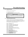
5
Troubleshooting
5.1
Section Overview................................................................................. 5-1
5.2
Troubleshooting Procedures ................................................................. 5-2
5.4
Filament Power Supply Fuse Replacement Procedure............................ 5-22
5.5
Suggested Spare Parts ....................................................................... 5-24
Attached Drawings
Pinout Table for Power Module Diagnostic Port (Rear Panel Connector J3)
0101-8241-0, Rev. F
i
CV-6SLX Technical Manual
This page has been intentionally left blank for pagination purposes.
0101-8241-0, Rev. F
ii
CV-6SLX Technical Manual
SUMMARY OF TERMS AND CONDITIONS OF SALE
THERE ARE NO EXPRESS OR IMPLIED
WARRANTIES THAT EXTEND BEYOND
THE WARRANTY HEREINABOVE SET
FORTH. THERE IS NO WARRANTY OF
MERCHANTABILITY OR FITNESS FOR A
PARTICULAR PURPOSE WITH RESPECT
TO THE APPARATUS OR ANY PART OR
COM-PONENT
THEREOF,
AND
NO
WARRANTY SHALL BE IMPLIED BY LAW.
MECHANICAL WARRANTY: For a period
of twelve (12) months from the date of original
shipment to Purchaser thereof, the apparatus and
each part or component manufactured by
Temescal, a part of Edwards Vacuum, Inc.,
hereinafter known as "Seller," is warranted to be
free from functional defects in materials and
workmanship. The foregoing warranty is subject
to the condition that the apparatus, part, or
component be properly operated under
conditions of normal use, and that regular
periodic maintenance and service be performed,
or replacements made, in accordance with
instructions provided by Seller. The foregoing
warranty shall not apply to any apparatus, part,
or component that has been repaired other than
by Seller or an authorized representative of
Seller, or in accordance with written instructions
provided by Seller; that has been altered by
anyone other than Seller; or that has been subject
to improper installation or abuse, misuse,
negligence, accident, or corrosion.
Items not of Seller’s manufacture but resold by
Seller are the products of other manufacturers
and their warranty, if any, shall apply. THERE
ARE NO WARRANTIES OF ANY KIND ON
PRODUCTS OF OTHER MANUFACTURERS
RESOLD BY TEMESCAL, EXCEPT THE
WARRANTY OF TITLE,
AND NO
WARRANTIES SHALL BE IMPLIED BY
LAW. THERE IS NO EXPRESS OR IMPLIED
WARRANTY OF MERCHANTABILITY OR
OF FITNESS FOR A PARTICULAR
PURPOSE WITH RESPECT TO PRODUCTS
OF OTHER MANUFACTURERS.
Purchaser’s sole and exclusive remedy under the
above warranty is limited to, at Seller’s option,
repair or replacement of defective parts or
components, or return to Purchaser of the price
of the apparatus. Any such obligation on
Seller’s part is subject to the following
requirements: (x) the defect must be promptly
reported to Seller; (y) if so advised by Seller,
Purchaser must return the part or component
with a statement of the observed deficiency not
later than seven (7) days after the expiration date
of the warranty to the address designated by
Seller, during normal business hours,
transportation charges prepaid; and (z) upon
examination by Seller, the part or component
must be found not to comply with the above
warranty. Return trip transportation charges for
the part or component shall be paid by
Purchaser. In the event that Seller elects to
refund the purchase price, the apparatus shall be
the property of Seller and shall be promptly
shipped to Seller at Seller's expense. This
mechanical warranty shall be void and the
apparatus shall be deemed to be purchased AS
IS in the event that the entire purchase price has
not been paid within thirty (30) days of original
shipment of the apparatus.
0101-8241-0, Rev. F
PERFORMANCE
WARRANTY:
Seller
warrants that the apparatus will comply with the
specifications set forth in the purchase order.
All specifications are subject to the corrections
and tolerances allowed by the NEC. If the
purchase order expressly provides for factory
testing to verify compliance with the
specifications, Purchaser shall be entitled to
witness the testing and the results of the testing.
Upon demonstration of compliance with the
specifications by factory testing, Seller’s liability
for failure to comply with the specifications shall
terminate. In the event that the purchase order
does not describe a comprehensive test program
for demonstration of compliance with the
specifications, Seller’s test program (which may
incorporate extrapolation of data or test results
based upon similarity of criteria established by
Seller) shall be used for such purpose.
If the purchase order does not expressly provide
for factory testing, compliance with the
specifications shall be demonstrated by field
testing which shall be conducted by Purchaser at
Purchaser’s expense. Seller shall have the right
to: (a) witness the field testing and to verify the
results of such field testing; (b) have free access
to all data compiled by Purchaser in connection
iii
CV-6SLX Technical Manual
with any field test; and (c) conduct its own field
test at its own expense during any fourteen-day
(14-day) consecutive period which may be
mutually agreed upon by Seller and Purchaser;
provided, however, that Seller shall have the
right to field test within six (6) months of receipt
from Purchaser of any notice of failure to
comply with the specifications. If compliance
with the specifications is to be demonstrated by
field testing, Purchaser shall conduct and
complete all field testing within sixty (60) days
of the original shipment of the apparatus and
shall promptly notify Seller of any failure to
comply with the specifications. Seller shall not
be liable for any failure to comply with the
specifications demonstrated by field testing
unless it receives notice thereof within sixtyseven (67) days of the date of original shipment
of the apparatus.
In the event that factory testing or field testing
does not demonstrate compliance with the
specifications, Purchaser’s sole and exclusive
remedy under the above warranty is limited to, at
Seller’s option, repair or replacement of
defective parts or components or return to
Purchaser of the purchase price of the apparatus.
In the event that Seller elects to refund the
purchase price, the apparatus shall be the
property of Seller.
Any obligations on Seller’s part under this
performance warranty are subject to the
following requirements: (x) the nature of the
failure of the apparatus to comply with the
specifications must be promptly reported to
Seller in writing; (y) if the apparatus has been
delivered and field tested, Purchaser must return
the apparatus or any part or component to Seller
upon its request, not later than sixty-seven (67)
days after initial shipment to Purchaser, to the
address designated by Seller, during normal
business hours, transportation charges prepaid;
and (z) upon examination and testing by Seller,
the apparatus must be found not to comply with
the specifications. Return trip transportation
charges for the apparatus or any part or
component shall be paid by Purchaser. This
performance warranty shall be void and the
apparatus shall be deemed to be purchased AS
IS in the event that the entire purchase price has
not been paid within thirty (30) days of original
shipment of the apparatus.
CV-6SLX Technical Manual
THERE ARE NO EXPRESS OR IMPLIED
WARRANTIES THAT EXTEND BEYOND
THE WARRANTY HEREINABOVE SET
FORTH. THERE IS NO WARRANTY OF
MERCHANTABILITY OR FITNESS FOR A
PARTICULAR PURPOSE WITH RESPECT
TO THE APPARATUS OR ANY PART OR
COMPONENT
THEREOF,
AND
NO
WARRANTY SHALL BE IMPLIED BY LAW.
DISCLAIMER OF LIABILITY: IN NO
EVENT SHALL SELLER BE LIABLE FOR
DIRECT, INDIRECT, SPECIAL, INCIDENTAL, OR CONSEQUENTIAL DAMAGES
ARISING FROM ANY SOURCE such as, but
not limited to, the manufacture, use, delivery
(including late delivery), or transportation of any
apparatus, part, or component sold to Purchaser,
whether such damages are caused by Seller’s
negligence or otherwise. Without limiting the
generality of the foregoing sentence, Seller shall
not be liable for: the cost of capital; the cost of
substitute
apparatus,
services,
repairs,
components, or parts; loss of profit or revenue;
the cost of power, whether purchased or
produced by the consumer thereof; loss of use of
the apparatus or any part thereof, or of any other
property owned by Purchaser; claims or costs of
Purchaser’s customers; injury to persons, or
death; or damages to any property. In the event
that any limited warranty or disclaimer of
liability is found to be unlawful or inapplicable,
or to have failed of its essential purpose, Seller’s
liability shall be limited to the amount paid by
Purchaser for the apparatus.
0101-8241-0, Rev. F
SAFETY INSTRUCTIONS FOR OPERATING AND SERVICE PERSONNEL
Operators and service personnel should always wear safety glasses. Operators shall not enter areas
intended for service access only. Only experienced service personnel should enter such areas, and
only after taking the preliminary precautions described in paragraphs 1 through 6 below.
DANGER
Potentially lethal voltages may exist within this unit, even with the line power switched off.
Service should only be attempted by qualified personnel. Failure to observe all safety
precautions may result in personal injury.
This component is designed to operate as part of a system containing high-voltage equipment.
Observe the precautions described below when servicing this system, especially when servicing
components where high voltages may be present.
1. Before servicing or operating this equipment, read all the component manuals supplied with the
system, paying special attention to safety instructions.
2. Post HIGH VOLTAGE WARNING signs in conspicuous locations within the service area.
3. Remove rings, watches, bracelets, and any other metal jewelry before working around high
voltage.
4. DO NOT WORK ALONE!
5. Be sure that all equipment is connected to a power receptacle having the correct polarity and
grounding, as prescribed by the local electrical codes. Refer to the power supply portion of the
documentation to determine the proper electrical ground for high-voltage components.
6. Before servicing any high-voltage component, switch off the electrical power at the component’s
main power switch. This switch should have a lockout feature. Lock the power off and keep the
key with you while you are working on the equipment.
7. Certain electrical parts (e.g., electrolytic capacitors) hold a lethal voltage even after the power is
switched off. Before entering any service area, use a grounding hook to discharge such parts. Be
sure that these parts are discharged before starting any repairs.
8. DO NOT touch high-voltage leads unless power is off and a grounding hook is connected to the
parts to be serviced.
9. The high-voltage components of the system should be equipped with electrical interlocks to
protect personnel from injury. DO NOT ATTEMPT TO DEFEAT, OVERRIDE, OR BYPASS
THESE PROTECTIVE DEVICES!
10. Never leave loose ends on high-voltage connections.
11. Observe the following warning if the system employs Radio Frequency (RF) power.
DANGER
RF radiation—even at modest power levels—can cause serious injury. If any of the RF
components (e.g., the RF power supply, the RF matching network, or the RF electrodes or
shielding inside the product chamber) are moved or changed in any way, the RF energy may
be radiated outside the equipment. Monitor the equipment to assure that external RF
radiation is below the levels prescribed by any and all applicable safety codes.
CV-6SLX Technical Manual
0101-8241-0, Rev. F
Special Amendment for United Kingdom Users
All Electrical Power Sources: Safety Precautions
This component is designed to be used in an extra-high-voltage system. Only authorized personnel
should be permitted to carry out work on this system.
Prior to any servicing, grounding hooks should be used to short out all high-voltage parts and
conductors in both the vacuum system and the high-voltage power supply. Screens protecting extrahigh-voltage conductors should be removed only if appropriate action has been taken to ensure that
extra-high-voltage conductors are dead and cannot be reenergized inadvertently.
In addition, all personnel should be aware of:
1. The Electricity (Factories Act) Special Regulations (1908 and 1944), in particular, Regulations
18(d) and 28 of the 1980 Regulations, as amended; and
2. The employer’s responsibility to set up suitable systems to safeguard the health and safety of
employees, according to the Health & Safety at Work etc. Act (1974).
CV-6SLX Technical Manual
0101-8241-0, Rev. F
USER RESPONSIBILITY
This equipment will perform in accordance with the instructions and information contained in the
user’s manual and its referenced documents when such equipment is installed, operated, and
maintained in compliance with such instructions. The equipment must be checked periodically.
Defective equipment shall not be used. Parts that are broken, missing, plainly worn, distorted, or
contaminated, shall be replaced immediately. Should such repair or replacement become
necessary, a telephone or written request for service should be made to Temescal, Livermore, CA,
a part of Edwards Vacuum, Inc.
The equipment, or any of its parts, shall not be altered without the prior written approval of
Temescal. The user and/or purchaser of this equipment shall have the sole responsibility for any
malfunction which results from improper use, faulty maintenance, damage, improper repair, or
alteration by any party other than Temescal.
GUIDELINES AND GOOD PRACTICES
1. Follow applicable clean room procedures (smocks, masks, gloves, etc.).
2. Do not expose the vent and purge valves to excessive pressures. The nitrogen line regulator is
factory set at 15 psi and must not be adjusted above 20 psi.
3. Prevent oil, grease, water, sweat, etc. from getting into the vacuum chamber.
4. Replace the source tray shield correctly to ensure that the ceramic parts or the high voltage
feedthroughs are protected from being coated.
5. Clean all mechanical parts and seals with lint-free paper/cloth soaked with isopropyl alcohol
(IPA). Dispose all IPA-exposed cleaning paper/cloth in a fireproof container, while ensuring
proper safety precautions are being followed.
6. Polish scratched surfaces with Scotch-Brite, taking care not to produce any cross scratches.
7. Shaft seals are all ferromagnetic. No lubrication is required.
8. Check the chamber door’s seal and sealing surfaces each time before closing it.
9. Check and clean with IPA the source tray seals and sealing surfaces each time before raising
the source tray into place.
10. Train staff by competent personnel. DO NOT allow staff to operate or do maintenance and
recovery work on the machine until they are trained by competent personnel.
11. Document all alarms, deviations, breakdowns, and servicings done on either a hardcopy or an
electronic equipment-log system.
CV-6SLX Technical Manual
0101-8241-0, Rev. F
HEALTH HAZARD
The condensates deposited on the tank walls of a vacuum system are generally in the form of
extremely fine particles. The nature, as well as the form, of the materials poses the following
potential health hazards:
a) Inhaling fine particles (powder) may cause damage to the lungs. To help prevent this, wear a
protective respirator mask with fine filter that has been approved by the National Institute for
Occupational Safety and Health (NIOSH) and the federal Mine Safety and Health
Administration (MSHA).
b) Some substances are toxic and inhaling them should be avoided. Take steps to ascertain
whether or not the material being deposited is a known toxic substance. Refer to the Material
Safety Data Sheet(s) covering the evaporant(s) in question.
c) Certain powders (titanium, for instance) can cause flash fires when exposed to oxygen or
other oxidizers. Therefore, when opening the chamber door after a deposition cycle, exercise
extreme caution and allow time for the coating surface to oxidize. Breakage of some of the
more reactive condensates may be hazardous, even when the above precautions are observed.
In this situation, fire-protective clothing should be worn.
d) Certain powders (platinum, for instance) are known to catalyze methyl alcohol vapors upon
contact, generating heat in the process and possibly causing a fire to erupt. Therefore, never
use methyl alcohol to wipe down or clean any internal tank surfaces of a vacuum system.
Use isopropyl alcohol (IPA), instead. Dispose of all IPA-exposed lint-free paper/cloth into a
fireproof container, while ensuring all proper safety procedures and precautions are being
followed.
CV-6SLX Technical Manual
0101-8241-0, Rev. F
1
PRODUCT DESCRIPTION
AND SPECIFICATIONS
1.1
Product Description
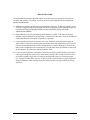
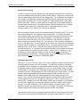
The Temescal Model CV-6SLX is a 6-kW, constant voltage, high-frequency, switching electron
beam power supply. Designed to power and control a single electron beam source, the CV-6SLX
is compatible with sources featuring either permanent-magnet or electromagnetic deflection.
The power supply delivers up to 10 kV at 600 mA, making it possible to achieve substantial
deposition rates in production environments. The CV-6SLX provides stable output at all voltage
levels, rapid arc recovery, ease of integration, and safety and convenience for operating as well
as service personnel.
The main components of the CV-6SLX power supply are the power module (see Fig. 1-1), the
filament power supply (see Fig. 1-2), and the control and high-voltage cables required to
connect them to each other and to the system control computer. Standard units also include a
remote control unit (see Fig. 1-3). For a detailed list of the components and cables included with
each power supply, see section 2.2. For complete installation instructions, see Section 2.
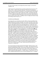
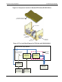
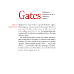
1.1.1 Power Module
Figure 1-1 shows the front panel of the CV-6SLX power module. For a detailed description of its
control and display features, see section 3.2.
Figure 1-1: CV-6SLX Power Module Front Panel
0101-8241-0, Rev. F
1-1
CV-6SLX Technical Manual
1.1 Product Description
Section 1: Product Description and Specifications
Power Module Specifications
Dimensions
8.75 in. H × 19 in. W × 23 in. D
Weight: 61 lbs.
Input Power
208-V Model CV-6SLX
208 V ac +10% /–5%, 50/60 Hz, 27 A, 60 Hz
3-phase delta (4-wire)
400-V Model CV-6SLX
400 V ac +10% /–5%, 50/60 Hz, 15 A, 50 Hz
3-phase wye (5-wire, with neutral)
High Voltage Output
6 kW at 10 kV max.
Fully adjustable 0–10 kV
Regulated to within ±5%
Beam Current
Fully adjustable, 0–600 mA dc
Regulated to within ±5%
Environmental Requirements
Must be free of corrosive vapors
Ambient temperature: 104° F (40° C) maximum
Humidity: 10%–90%, noncondensing
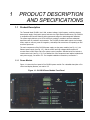
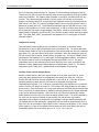
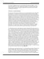
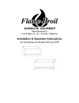
1.1.2 Filament power supply
Figure 1-2 shows the filament power supply, a stand-alone assembly that must be installed near
the vacuum chamber.
Figure 1-2: Filament Power Supply Front Panel
CV-6SLX Technical Manual
1-2
0101-8241-0, Rev. F
Section 1: Product Description and Specifications
1.1 Product Description
Filament Power Supply Specifications
Dimensions: 6.5 in. H × 6.5 in. W × 11 in. D
Weight: 14 lbs.
Input Power: 220 V ac ±10%, 6.25 A, 50-60 Hz, single-phase
Power Output: 10 V ac, 50 A, 40 kHz max.
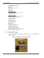
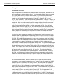
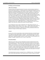
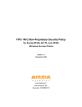
1.1.3 Remote Control Unit
Figure 1-3 shows the half-rack remote control unit, whose dimensions are 5.24 in. high × 9.5 in.
wide. For a detailed description of this unit’s control and display features, see section 3.4.
Figure 1-3 Remote Control Unit
1.1.4 Interconnection Cables
The CV-6SLX is available in a GUI-driven-only version, which does not include a remote control
unit. That version has a different cable set from the standard CV-6SLX power supply, which
comes with a remote controller. For a detailed list of the components and cables included with
each version of the power supply, see section 2.2.
0101-8241-0, Rev. F
1-3
CV-6SLX Technical Manual
1.1 Product Description
CV-6SLX Technical Manual
Section 1: Product Description and Specifications
1-4
0101-8241-0, Rev. F
2
INSTALLATION
2.1
Section Overview
This section describes the installation procedures required for proper operation of the CV-6SLX
power supply. The topics covered are:
Section
Section
Section
Section
Section
Section
Section
Section
2.2
2.3
2.4
2.5
2.6
2.7
2.8
2.9
List of Components and Cables Supplied with the Unit
Rack Mounting the Power Module
Rack Mounting the Remote Control Unit
Mounting the Filament Power Supply
Grounding Requirements
Cable Installation on Standard Units
Cable Connections on Units Without a Remote Controller
Initial Power Up/Maintenance Power Up Procedure
To install a standard CV-6SLX unit (i.e., a unit equipped with the remote gun controller), follow
the instructions in sections 2.3 through 2.7 plus those in section 2.9, skipping section 2.8. To
install a CV-6SLX unit without a remote controller, follow the instructions in sections 2.3, 2.5,
2.6, 2.8 and 2.9, skipping sections 2.4 and 2.7.
CAUTION
Before beginning the installation procedure, make sure that the facility circuit breaker supplying
power to the CV-6SLX is switched OFF and locked out with an appropriate lockout/tagout device.
Also make sure that the FPS ON/OFF switch and the circuit breaker switch (labeled AC MAINS) on
the power module front panel are both in the OFF position. The facility breaker must remain locked
and tagged out during the entire installation procedure. Likewise, the power module’s main circuit
breaker switch and the FPS ON/OFF switch must both remain in the OFF position during the entire
installation procedure. The Initial Power Up/Maintenance Power Up Procedure (see section 2.9)
specifies the exact sequence in which the power is to applied to the unit.
2.2
List of Components and Cables Supplied with the Unit
2.2.1 Standard Units (With Remote Controller)
The components and cables listed below are supplied with standard units (i.e., units with a
remote controller). These units will have the top-level PN 0620-9600-2 (for 208-volt units) or PN
0620-9600-3 (for 400-volt units).
•
•
•
•
•
•
•
•
0101-8241-0, Rev. F
CV-6SLX power module, PN 6024-7110-0 (= 208-volt unit) or 6024-7120-0 (= 400-volt unit)
Filament power supply, PN 0620-6604-0 or 0620-6604-2
Remote control unit, PN 0620-9750-0
Rack-mounting kit for remote control unit, PN 0411-6183-2
FPS input power cable, PN 6622-0100-20
Power module-FPS cable, PN 6338-2884-0
HV control cable, PN 0620-9840-0
Gun control cable, PN 0620-9730-0
2-1
CV-6SLX Technical Manual
2.3 Rack Mounting the Power Module
•
•
•
•
•
•
•
Section 2: Installation
Gun Control-system I/O cable, PN 0620-9730-1
HV coaxial cable, PN 6024-6112-1
HV cable/conduit assembly, PN 0620-9654-0
Bracket (PN 0040-9982-0) for securing HV conduit to source tray
16” grounding hook, PN 9900-4864-0
20’ coil of 3”-wide copper strap, PN 5621-0032-3
One copy of CV-6SLX Technical manual
2.2.2 Units Without a Remote Controller
The components and cables listed below are supplied with units without a remote controller.
These units will have the top-level PN 0620-9600-0 (for 208-volt units) or PN 0620-9600-1 (for
400-volt units)
•
•
•
•
•
•
•
•
•
•
•
2.3
CV-6SLX power module, PN 6024-7110-0 (= 208-volt unit) or 6024-7120-0 (= 400-volt unit)
Filament power supply, PN 0620-6604-0 or 0620-6604-2
FPS input power cable, PN 6622-0100-20
Power module-system I/O cable (PN 6338-2886-0
Two 20’ DB15M/DB15F cables (PN 6338-2884-0), one to serve as the power module-FPS
cable, the other to serve as the FSP-system I/O cable
HV coaxial cable, PN 6024-6112-1
HV cable/conduit assembly, PN 0620-9654-0
Bracket (PN 0040-9982-0) for securing HV conduit to source tray
16” grounding hook, PN 9900-4864-0
20’ coil of 3”-wide copper strap, PN 5621-0032-3
One copy of CV-6SLX Technical manual
Rack Mounting the Power Module
2.3.1 General Installation Guidelines
The CV-6SLX power module can be rack mounted in a standard 19" rack cabinet. It must be
supported by two side shelf supports to hold the power supply weight. The rack vertical height
required is 8-3/4 inches. The chassis depth is 23 inches. An additional 3" is required for
clearance of terminals, plugs, and wiring. The panel should be secured to the rack cabinet by
the four mounting holes provided.
DANGER: HIGH VOLTAGE
Removal of the power module top cover can expose personnel to dangerous or lethal voltages.
Particular care should be taken regarding high voltage, which can arc over a considerable
distance. It is not necessary to be in physical contact with a live terminal in order for an arc to send
a lethal high-voltage discharge through a person’s body.
The power module is designed to be installed in an indoor laboratory or clean room in which the
immediate environment is controlled to maintain an ambient temperature of 40° C or lower and
a noncondensing humidity level of 10%-90%. The screen covering the front panel air vent and
the screen sandwiched between the exhaust fan and the rear panel provide IP40 ingress
protection. These screens prevent solid foreign objects larger than 1 mm in diameter from
penetrating the outside chassis but do not provide a barrier against liquids. Both screens must
CV-6SLX Technical Manual
2-2
0101-8241-0, Rev. F
Section 2: Installation
2.4 Rack Mounting the Remote Control Unit
be removed and cleaned whenever the fan airflow drops more than 15% from its original value
or every two years, whichever comes first. The power module does not require any routine
maintenance, aside from the cleaning of the screens.
2.3.2 Air Flow Requirements
The inverters have a temperature sensor that will shut down and latch out further operation if
an overtemperature condition should occur. The customer must ensure a free flow of air is
maintained through the cabinet and keep the ambient air temperature at the input to the power
supply below 104° F (40° C). All air passages must be unobstructed. If air filters are used on the
cabinet air input, they should be checked on a regular schedule for dirt and dust accumulation.
CAUTION
Cabinet doors and panels must not block air vents located on the unit’s front and rear panels, providing
at least 2” of clearance from these vents. A fan located on the rear panel pulls air in through the vents
on the front panel, and exhausts warmer air through the rear vent.
2.4
Rack Mounting the Remote Control Unit
A mounting kit (PN 0411-6183-2) is provided with the unit to facilitate rack mounting the remote
controller in a standard 19” electronics rack. First assemble the kit’s mounting hardware inside
the rack. Then secure the remote controller to the mounting hardware.
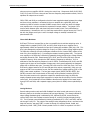
2.5
Mounting the Filament Power Supply
Install the FPS module in the vacuum cubicle, within 6 feet of the high-voltage feedthoughs that
supply power to the e-beam gun. To do so, first drill four holes at the installation location, in the
pattern shown in Figure 2-1. Then place the holes in the bottom of the FPS module over the
drilled holes and secure the FPS in place with the hardware provided.
DANGER: HIGH VOLTAGE
Removal of any of the covers on the FPS module can expose personnel to dangerous or lethal
voltages. Particular care should be taken regarding high voltage, which can arc over a
considerable distance. It is not necessary to be in physical contact with a live terminal in order for
an arc to send a lethal high-voltage discharge through a person’s body.
Figure 2-1 Mounting Hole Pattern for FPS Module
5. 35"
4.13"
0101-8241-0, Rev. F
Hole Diameter = . 25"
2-3
CV-6SLX Technical Manual
2.6 Grounding Requirements
2.6
Section 2: Installation
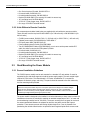
Grounding Requirements
2.6.1 Facility Low-Impedance Grounding Requirements
Safe, dependable operation of the power supply cannot be ensured unless a good earth ground
is provided for the system and the power supply. This ground must provide a low-impedance
path for radio frequency (RF) as well as direct current (dc) electricity, and it must not be
connected to that of any other system or equipment. Figure 2-2 shows two different methods of
providing the required low-impedance ground on the facility side of the installation.
Figure 2-2 Facility Low Impedance Grounding Requirements
CV-6SLX Technical Manual
2-4
0101-8241-0, Rev. F
Section 2: Installation
2.6 Grounding Requirements
The installation of twin rods of copper-clad steel is preferred. However, if the equipment is to be
installed on the upper floors of a building, the system can be grounded by connecting the
vacuum chamber to the steel structure of the building. Where copper straps are attached to
frame members, the copper must be bolted to clean, bare patches of metal. The length of
copper strap connected to the source tray must be securely bolted to a clean site on that part.
CAUTION
Do not use braided wire for any ground connections.
CAUTION
Do not rely on water pipes to establish the system ground connection. Multiple plumbing
joints, each with tape and/or sealing compounds, make such a ground unreliable.
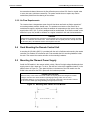
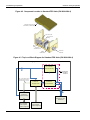
2.6.2 System Low-Impedance Grounding
Within the vacuum system, the low-impedance ground is provided by 3”- and 1”-wide copper
straps. As Figure 2-3 shows, these straps must connect:
the grounding stud labeled RF GND on the power module’s rear panel (see Figure 2-4) to a
grounding point on the frame of the operator station
• the operator station’s grounding point to the vacuum cubicle’s central grounding point
• the grounding stud labeled RF GND on the FPS front panel (see Figure 2-5) to the vacuum
cubicle’s main grounding point
• the source tray to the vacuum cubicle’s main grounding point.
•
Figure 2-3 System Low Impedance Grounding Requirements
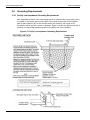
2.6.3 Power Module Grounding
Make connections to the power supply’s grounding lugs as shown in attached drawing 620-9692,
following the procedure described below.
0101-8241-0, Rev. F
2-5
CV-6SLX Technical Manual
2.6 Grounding Requirements
Section 2: Installation
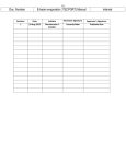
Step
1
2
Action
A roll of 3”-wide copper strap (PN 5621-0032-3) is supplied with the
unit. Cut off a length of this strap that will easily extend from the
grounding lugs on the power module’s rear panel to the operator
station’s frame.
Secure one end of this strap to the grounding stud labeled RF GND on
the power module’s rear panel (see Figure 2-4).
Figure 2-4 Power Module Rear Panel
3
Secure a length of #10 AWG wire to the grounding lug labeled GND
on the power module rear panel.
4
Secure the loose end of the 3” copper strip and the loose end of the
#10 AWG ground wire to a clear, bare patch of metal on the operator
station’s frame. The same fastener that secures the above copper strip
to the frame should also secure one end of a length of 3” copper strap
that connects to the vacuum cubicle’s central grounding point, as
shown in Figure 2-3.
2.6.4 Filament Power Supply Grounding
Make connections to the grounding lugs on the FPS front panel as shown in attached drawing
620-9692, following the procedure described below.
CV-6SLX Technical Manual
Step
1
Action
Obtain a length of 1”-wide copper strap (user-supplied) that will easily
extend from the filament power supply to the vacuum cubicle’s central
grounding point.
2
Secure one end of this strap to the grounding stud labeled RF GND on
the FPS front panel (see Figure 2-5).
2-6
0101-8241-0, Rev. F
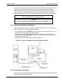
Section 2: Installation
2.7 Cable Installation on Standard Units
Figure 2-5 Grounding Studs on FPS Front Panel
RF Ground. Connect to vacuum
cubicle’s central gounding point,
using 1”-wide copper strap.
Chassis Ground. Connect to vacuum
cubicle’s central gounding point, using
#10 AWG wire.
3
Secure a length of #10 AWG wire to the other grounding lug on the
FPS front panel.
4
Secure the free ends of the 1” copper strip and the #10 AWG ground
wire to the vacuum cubicle’s central grounding point.
2.6.5 Electron Beam Source Ground
To ensure a good ground between the electron beam source and the vacuum cubicle, the
following conditions must be met:
The base of the source and the surface on which it is mounted (usually the upper surface of
the source tray) must be clean and free of evaporated material.
• The mounting surface must be made of nonmagnetic material.
• The source must be securely bolted to the mounting surface.
•
2.6.6 Mounting the Grounding Hook
If your are installing the CV-SLX unit in a system that does not already have a properly mounted
grounding hook, install the grounding hook provided with the power supply in the vacuum
cubicle, attaching its pigtail to the vacuum cubicle’s central grounding point and the grounding
hook’s storage bracket at a convenient location nearby.
2.7
Cable Installation on Standard Units
On standard CV-6SLX units (i.e., units equipped with the remote gun control unit) connect
cables as shown in Figure 2-4.
0101-8241-0, Rev. F
2-7
CV-6SLX Technical Manual
2.7 Cable Installation on Standard Units
Section 2: Installation
Figure 2-4 Cabling Diagram for Standard CV-6SLX
CV-6SLX Technical Manual
2-8
0101-8241-0, Rev. F
Section 2: Installation
2.7 Cable Installation on Standard Units
2.7.1 Connecting the Input Power Cables
Connecting the Power Module Input Power Cable
The CV-6SLX is available for the following input voltages:
•
208-V Model CV-6SLX (PN 6024-7110-0), 50/60 Hz, 3-Phase delta, 4-wire
Connect using AWG #10 stranded UL1015 wire
•
400-V Model CV-6SLX (PN 6024-7120-0), 50/60 Hz, 3-Phase wye, 5-Wire with neutral
Connect using AWG #12 stranded UL1015 wire
The input power cable is user supplied and must conform to the specifications listed above.
Connect the power cable’s conductors as shown in Figure 2-5.
Figure 2-5 Input Power Connections on Power Module Rear Panel
208-Volt CV-6SLX
TB1
AC INPUT
3 ~ 36 0-4 40V 15A 50-6 0 HZ
L1
L2
L3
GND
Ground Wire
400-Volt CV-6SLX
TB1
AC INPUT
3 ~ 3 60 -4 4 0 V 1 5 A 5 0-6 0 HZ
L1
L2
L3
N
Neutral Wire
0101-8241-0, Rev. F
2-9
Ground Wire
GND
CV-6SLX Technical Manual
2.7 Cable Installation on Standard Units
Section 2: Installation
Connecting the FPS Input Power Cable (PN 6622-0100-20)
The FPS power cable (PN 6622-0100-20) is provided with the unit. Plug one end of this cable
into rear panel connector J2 on the CV-6SLX power module (see Figure 2-4). Plug the other end
into the power receptacle on the FPS front panel (see Figure 2-6).
CAUTION
Make sure that the ON/OFF switch on the FPS front panel (see Figure 2-6)
remains in the OFF position until instructed otherwise in section 2.9.
Figure 2-6 Input Power Receptacle on FPS Front Panel
FPS
ON/OFF Switch
Plug in 208-V power cable
(PN 6622-0100-20) here.
2.7.2 Connecting the HV Output Cables and Conduit (PN 0620-9654-0)
The cables that conduct the high voltage from the FPS to the source tray are contained in a
length of flexible conduit. The part number of the HV cable/conduit assembly is 0620-9654-0. In
connecting this assembly to the FPS and to the source tray, follow the instructions provided
below.
Connecting the HV Output Cables and Conduit to the FPS
Connect the HV cable/conduit assembly to the FPS rear panel (see Figure 2-7), following the
procedure described below.
CV-6SLX Technical Manual
2-10
0101-8241-0, Rev. F
Section 2: Installation
2.7 Cable Installation on Standard Units
Step
1
Action
Remove four screws that secure the conduit panel to the FPS rear
panel, as shown below.
Figure 2-7 Removing the FPS Conduit Panel
2
Insert the threaded end of the conduit elbow into the hole in the
conduit panel and secure the elbow with the nut provided, as shown
in Figure 2-8.
Figure 2-8 Conduit Properly Secured to FPS Conduit Panel
3
0101-8241-0, Rev. F
Figure 2-9 shows a portion of the FPS rear panel with the conduit
panel removed. Plug the banana connectors on the ends of the HV
cables into the receptacles shown in the illustration.
2-11
CV-6SLX Technical Manual
2.7 Cable Installation on Standard Units
Section 2: Installation
Figure 2-9 FPS Receptacles for Banana Plugs on HV Output Cables
4
Replace the conduit panel, taking care to secure it in place with all
four screws.
Connecting the HV Ouput Cables and Conduit at the Source Tray
Connect the other end of the HV output cables to the HV feedthroughs in the source tray,
following the instructions provided below.
CAUTION
If the vacuum system has previously been in use with a high-voltage power
supply, then before performing this procedure, touch the source tray and the
terminals on both HV feedthroughs with a properly connected grounding hook.
Step
1
Action
Remove the nut that secures one of the feedthroughs to the underside
of the source tray.
2
Install the HV conduit bracket (PN 0040-9982-0) supplied with the unit
and secure it with the nut removed in Step 1, as shown in Figure 2-10.
Figure 2-10 HV Conduit Bracket Properly Installed on HV Feedthrough
3
CV-6SLX Technical Manual
Using the nut supplied with the conduit, secure the conduit to the
bracket as shown in Figure 2-11.
2-12
0101-8241-0, Rev. F
Section 2: Installation
2.7 Cable Installation on Standard Units
Figure 2-11 HV Conduit Properly Secured to Bracket
4
Secure the lugs on the ends of the HV cables to the feedthroughs, as
shown in Figure 2-10. Either cable can be connected to either
feedthrough, as polarity is not an issue.
2.7.3 Connecting the HV Coaxial Cable (PN 6024-6112-1)
The HV coaxial cable (PN 6024-6112-1) conducts the high voltage output of the power module
to the FPS. Connect this cable to power module rear panel connector J1 and to the HIGH
VOLTAGE IN connector on the FPS.
2.7.4 Connecting the Remaining Cables to the Remote Controller and FPS
Connect the remaining cables to the power module, the FPS, and remote controller, following
the instructions provided below. Figure 2-12 shows the connectors on the remote controller’s
rear panel.
Figure 2-12 Remote Controller Rear Panel
0101-8241-0, Rev. F
2-13
CV-6SLX Technical Manual
2.7 Cable Installation on Standard Units
Section 2: Installation
Step
1
Action
Plug the power module-FPS cable into J5 on the power module rear
panel and into FPS connector J102 (see Figure 2-13).
2
Plug the gun control cable (PN 0620-9730-0) into connector G1J1 on
the remote controller and into J101 on the FPS (see Figure 2-13).
Figure 2-13 FPS Cabling Detail on Standard Units
Connect female end of FPS-Power
Module cable (PN 6338-2884-0) to
J102. Connect the male end of that
cable to J5 on power module rear
panel, as shown in Figure 2-4.
Connect male end of FPS-Gun
Controller cable (PN 620-9730-0) to
J101. Connect the female end of that
cable to G1J1 on the remote control
unit, as shown in Figure 2-4.
CAUTION
Connect the power module-FPS cable and the gun control cable exactly
as described above. Incorrect connection of these cables will result in
damage to the power supply.
3
Plug the single male D connector on one end of the HV control cable
(PN 0620-9840-0) into power module connector J4 (see Figure 2-4).
4
Plug the female D connector on the other end of the HV control cable
into HVJ2 on the remote controller (see Figure 2-12).
5
The remaining connector on the end of the HV control cable is a 28pin circular connector. Plug this connector into HVJ1 on the remote
controller rear panel (see Figure 2-12).
2.7.5 Making I/O Connections to the Control System
The installer must make connections (1) between the control system and gun control-system I/O
cable (PN 0620-9730-1) and (2) between the control system and the HV control-system I/O
cable (PN 0620-9840-0). Control inputs and status outputs include both digital and analog
signals. Digital inputs require a simple contact closure and carry 24 V dc at approximately 20
mA. All digital outputs are from contact closures rated at 2 A @ 220 V ac or at 2A @ 30 V dc.
CV-6SLX Technical Manual
2-14
0101-8241-0, Rev. F
Section 2: Installation
2.7 Cable Installation on Standard Units
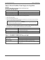
Making Connections to the HV Control-System I/O Cable (PN 0620-9840-0)
System I/O-HV control connections are made via unterminated end of the HV control-system I/o
cable. For detailed information about these I/Os, see Figure 2-14 and Table 2-1.
Figure 2-14 Signals Exchanged via the HV Control-System I/O Cable (PN 0620-9840-0)
Pin
No.
HV IS READY
HV IS ON
ACTUAL HIGH-VOLTAGE
(0 to +10 V dc)
TOTAL POWER SUPPLY
CURRENT (0 to +10 V dc)
+
_
+
_
1
5
2
6
3
7
4
9
15
16
18
19
21
22
23
Wire
Color
R
BK
W
BK
G
BK
HV GO OFF*/ENABLE
BL
BK
HV GO ON
BR
BK
W
R
+
_
Shield
REMOTE HIGH-VOLTAGE
REQUEST (0 to +10 V dc)
O
BK
Table 2-1 Additional Information About Signals Exchanged via the HV Control-System I/O Cable
Digital Control Inputs
Signal Name
HVJ2
Pins
Wire
Colors
HV GO OFF*/
ENABLE
3
7
G
BK
A momentary open pulse switches off the high voltage. If all HV control interlocks are made,
contact closure of this line enables the HV to be switched on. NOTE: If these pins are not
connected to a remote contact closure, they must be jumpered together, or the HV cannot be
switched on.
HV GO ON
4
9
BL
BK
If all HV control interlocks are made and the HV GO OFF*/ENABLE loop is closed, a momentary
contact closure switches on the high voltage.
Function
Analog Control Input
HVJ2
Pins
Wire
Colors
18
19
W(+)
R(-)
HVJ2
Pins
Wire
Colors
HV IS READY
1
5
R
BK
Indicates that all HV control interlocks are made and that the HV GO OFF*/ENABLE loop is closed;
the HV is ready to be switched on.
HV IS ON
2
6
W
BK
Indicates that the high voltage is on.
Signal Name
HVJ2
Pins
Wire
Colors
ACTUAL HIGH
VOLTAGE
15
16
BR(+)
BK(-)
Linearly represents the load (gun) voltage: 0 V = 0 Kv; 10 V = 10 kV
TOTAL POWER
SUPPLY
CURRENT
22
23
O(+)
BK(-)
Linearly represents the total power supply’s total current output: 0 V = 0 A; 10 V = 1 A.
Signal Name
REMOTE HV
REQUEST
Function
If the HV control unit's VOLTAGE REQUEST REMote/RANGE switch is in the REMOTE position, this
input linearly controls the high voltage. NOTE: This input must be 0 V dc to +10 V dc. The HV
circuit cannot be controlled by a –10 V dc input.
Digital Outputs
Signal Name
Function
Analog Outputs
0101-8241-0, Rev. F
Function
2-15
CV-6SLX Technical Manual
2.7 Cable Installation on Standard Units
Section 2: Installation
Making Connections to the Gun Control-System I/O Cable (PN 0620-9730-1)
To make I/O connections between the control system and the remote controller’s gun control
panel, perform the procedure described below.
Step
1
Action
Plug the circular connector on end of the system I/O-gun control cable
(PN 0620-9730-1) into remote controller rear panel connector G1J2
(see Figure 2-12).
2
Make the required I/O connections between the control system and
the unterminated end of the system I/O-gun control cable. For
detailed information about these I/O connections, see Figure 2-15 and
Table 2-2.
Figure 2-15 Signals Exchanged via the Gun Control-System I/O Cable (PN 0620-9730-1)
Pin
No. Wire
Color
GUN IS READY
GUN IS ON
ACTUAL EMISSION CURRENT
(0 to +10 V dc)
CV-6SLX Technical Manual
+
_
Shield
1
2
3
4
5
6
7
8
13
14
15
16
18
19
20
21
22
23
24
25
26
27
50
51
55
56
57
2-16
R
BK
W
BK
G
BK
REMOTE GUN GO OFF*/ENABLE
BL
BK
REMOTE GUN GO ON
O
BK
TANK INTERLOCK
W
R
VACUUM GAUGE INTERLOCK
G
R
AUXILIARY INTERLOCK
(if not used, jumper Pins 18 and 19)
BL
R
GUN WATER INTERLOCK
Y
R
POSITION INTERLOCK (0 to 10 V dc)
+
Y
_
BK
+
BR
_
BK
BR
FILAMENT CURRENT
MONITOR
FILAMENT BIAS
SET (0 to 10 V dc)
R
Shield
O
R
+
_
REMOTE EMISSION CURRENT
REQUEST (0 to +10 V dc)
0101-8241-0, Rev. F
Section 2: Installation
2.7 Cable Installation on Standard Units
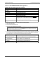
Table 2-2 Additional Details About Signals Exchanged via the Gun Control-System I/O Cable
Digital Interlock Inputs (Required)
G1J2
Pins
Wire
Colors
TANK INTERLOCK
13
14
O
BK
Prevents the gun from being switched on unless all vacuum system doors and covers are
closed and locked.
VACUUM GAUGE
INTERLOCK
15
16
W
R
Ensures that product chamber ion gauge is on before gun is switched on.
AUXILIARY
INTERLOCK
18
19
G
R
Customer defined. Generally used with multipocket sources to ensure that the beam is OFF
while the turret is rotating. If no external input is supplied, this input must be jumpered ON.
GUN WATER
INTERLOCK
20
21
BL
R
Prevents the gun from being switched on unless it is receiving sufficient cooling water. Signal
to be supplied by a customer-installed flow switch.
POSITION
INTERLOCK
22
23
Y
R
If supplied by a beam sweep controller, this input switches off the gun if the beam travels
beyond the sweeper’s programmed position limits. If signal is not supplied by a sweep
controller, these pins must be jumpered.
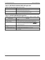
Signal Name
Function
Analog Control Input
Signal Name
REMOTE EMISSION
CURRENT REQUEST
G1J2
Pins
Wire
Colors
56
57
O(+)
R(-)
Function
If the gun control unit's REMote/RANGE switch is in the REMOTE position, this input linearly
controls emission current. 0 V = min. current; +10 V = full scale. On standard FPS units (i.e.,
PN 0620-6604-0), full scale = 600 mA. On units equipped with FPS PN 0620-6604-2, full scale
= 1 A. NOTE: In both cases, the actual maximum emission current output is 600 mA.
Digital Control Inputs
G1J2
Pins
Wire
Colors
REMOTE
GUN GO OFF*
/ENABLE
5
6
G
BK
A momentary open pulse switches off the gun. If all gun control interlocks are made, the gun
can be switched on again. NOTE: If these pins are not connected to a remote contact closure,
they must be jumpered together, or the gun cannot be switched on.
REMOTE
GUN GO ON
7
8
BL
BK
If all gun control interlocks are made and the GUN GO OFF*/ENABLE loop is closed, a 2-sec.
contact closure across these pins switches on the gun.
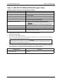
FILAMENT CURRENT
MONITOR
24
25
Y
BK
A 0 to 7.5 volt signal proportional to 0-75 amperes is available for driving a remote meter.
The impedance should be 1 megohm or higher.
FILAMENT BIAS SET
26
27
BN
BK
This input controls the filament bias current. Range: 0 V dc to +10 V dc. On all FPS units,
0 V dc = 0 A. On standard FPS units (i.e., PN 0620-6604-0), +10 V dc = 50 A. On units
equipped with FPS PN 0620-6604-2, +10 V dc = 100 A.
G1J2
Pins
Wire
Colors
GUN IS READY
1
2
R
BK
Indicates that all gun control interlocks are made and that the GUN GO OFF*/ENABLE loop is
closed, so the gun can be switched on.
GUN IS ON
3
4
W
BK
Indicates that the gun is switched on.
G1J2
Pins
Wire
Colors
50
51
BR(+)
R(-)
Signal Name
Function
Digital Outputs
Signal Name
Function
Analog Output
Signal Name
ACTUAL EMISSION
CURRENT
0101-8241-0, Rev. F
Function
Linearly represents the actual emission current: 0 V = 0 A; 10 V = 600 mA.
2-17
CV-6SLX Technical Manual
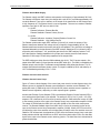
2.8 Cable Connections on Units Without a Remote Controller
2.8
Section 2: Installation
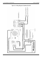
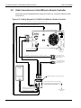
Cable Connections on Units Without a Remote Controller
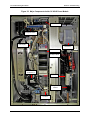
On CV-6SLX units not equipped with the remote gun control unit, connect the cables as shown
in Figure 2-16.
Figure 2-16 Cabling Diagram for CV-6SLX Units Without a Remote Controller
6024-6112-1 HIGH VOLTAGE COAXIAL CABLE
6622-0100-20 208-VOLT POWER CABLE
CV -6 S LX P OW ER M ODUL E
RF GND
J3
DIAGN OSTICS
J1
H V O UTP UT
J2
J4
H VPS CON TRO L I/O
!
J5
FILAMEN T I/O
F2
5621-0032-3
F1
TB1
AC IN PUT
L1 L2 L3
GN D
#1 0 A W G W IR E
INPUT POWER CABLE
SINGLE-POINT
GROUND
(USER SUPPLIED)
6338-2886-0
HV CONTROL I/O
TO/FROM SYSTEM
SEE TABLE 2-3
POWER MOD ULE-SYSTEM I/O CABLE
6338-2884-0
POWER MODU LE-FPS C ABLE
6338-2884-0
FPS-SYSTEM I/0 CABLE
GUN CONTROL I/O
TO/FROM SYSTEM
SEE TABLE 2-4
PROCESS
CHAMBER
ELECTRON BEAM
SOURCE
F IL AM E N T PO WE R S UP PLY F RON T P AN E L
J102
J101
RF GN D ( CO PP ER ST R AP , US ER SUP PL IE D)
CH A SS IS G N D ( #1 0 A WG W IRE )
CONNECT TO FPS REAR PANEL
AS DESCRIBED IN SECT. 2.5.2
SINGLE-POINT
GROUND
0620-9654-0 HV CONDU IT
C ONNEC T AT SOU RCE TRAY
A S DESCRIBED IN SECT. 2.5.2
6024-6112-1
CV-6SLX Technical Manual
HIGH VOLTAGE COAX IAL C ABLE
2-18
0101-8241-0, Rev. F
Section 2: Installation
2.8 Cable Connections on Units Without a Remote Controller
2.8.1 Connecting Cables on Units Without a Remote Controller
Step
1
Action
Connect the input power cables for the power module and the FPS as
described in section 2.5.1.
2
Connect the HV coaxial cable as described in section 2.5.2.
3
Connect the HV output cables and conduit as described in section
2.5.3.
4
Plug the male end of the power module-system I/O cable (PN 63382886-0) into connector J4 on the power module rear panel (see Figure
2-4.
5
Plug the male end of the power module-FPS (PN 6338-2884-0) into
connector J5 on the power module rear panel (see Figure 2-16).
6
Plug the female end of the power module-FPS cable into connector
J102 on the FPS front panel (see Figure 2-17).
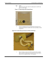
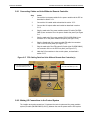
7
Plug the male end of the FPS-system I/O cable (also PN 6338-2884-0)
into connector J101 on the FPS front panel (see Figure 2-17).
8
Make the I/O connections to the control system, as described in
section 2.8.2.
Figure 2-17 FPS Cabling Detail on Units Without Remote Gun Controller(s)
Connect FPS-system I/O cable
(also PN 6338-2884-0) to J101.
Connect FPS-Power Module cable
(PN 6338-2884-0) to J102.
2.8.2 Making I/O Connections to the Control System
The installer must make connections (1) between the control system and the power module–
system I/O cable (PN 6388-2886-0) and (2) between the control system and the FPS–system
0101-8241-0, Rev. F
2-19
CV-6SLX Technical Manual
2.8 Cable Connections on Units Without a Remote Controller
Section 2: Installation
I/O cable (PN 6388-2884-0). If necessary, remove the female D connectors from the ends of
these two cables. Control inputs and status outputs include both digital and analog signals.
Digital inputs require a simple contact closure and carry 24 V dc at approximately 20 mA. All
digital outputs are from contact closures rated at 2 A @ 220 V ac or at 2A @ 30 V dc.
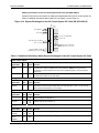
Making Connections to the Power Module-System I/O Cable (PN 6388-2886-0)
The power module–system I/O cable plugs into connector J4 on the power module’s rear-panel.
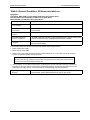
Table 2-3 shows the pinout for control system end of that connector, cross-references signal
names to wire colors, and provides additional information about most of the inputs and outputs.
Table 2-3 Signals Exchanged via the Power Module–System I/O Cable (PN 6338-2886-0)
CV -1 6 SLX PO W ER M O D U LE
6338-2886-0
(DB-25)
J4
KV SET IN
1
1
ANALOG COMMON
2
2
KV MONITOR OUT
3
4
3
mA MONITOR OUT
REM/LCL IN
5
4
5
I/O SWITCHES POWER
6
6
DIGITAL COMMON
7
7
HV ON IN +
HV ON IN -
8
8
9
9
10
RESET +
RESET -
10
11
11
HV ON IND OUT
FAULT IND OUT
12
12
13
14
13
OUT OF REG IND OUT
INTERLOCK OK IND OUT
15
15
16
16
HV OFF IN +
17
17
HV OFF IN -
18
SPARE
19
18
19
READY IND OUT
14
SPARE
20
20
SPARE
SPARE
21
21
22
23
22
24
24
25
25
SPARE
REMOTE INTERLOCK +
REMOTE INTERLOCK -
23
SHELL
WHT/GRN
WHT/ORG
WHT/RED
ORG/WHT
WHT/BRN
BRN/WHT
RED/WHT
WHT/BLK
WHT/BLU
BLU/WHT
BLU
BRN
VIO
GRY
BLK/WHT
GRN
WHT
RED
BLK
YEL
ORG
GRN/YEL
GRN/WHT
PNK
TAN
SHIELD
1
2
KV SET IN, 0-10 VDC in for 0-10 kV
ANALOG COMMON
3
KV MONITOR OUT, 1-10 VDC for 0-10 kV
mA MONITOR OUT, 0-10 VDC for 0-2.0 A
4
5
6
7
8
9
REM/LCL IN, 10-24 V DC; high selects remote HV control
I/O SWITCHES POWER
DIGITAL COMMON
HV ON IN +, 15-24 V DC input, maintained for HV ON
HV ON IN -, HV ON signal return (if externally sourced)
10
RESET IN +, Momentary 15-24 V DC input to reset faults
11
RESET IN -, RESET signal return (If ext. sourced)
HV ON IND OUT, 15-24 VDC = HV IS ON
12
13
FAULT IND OUT, 15-24 VDC = FAULT OCCURED
14
READY IND OUT, 15-24 VDC = HVPS READY
15
OUT OF REG IND OUT, 15-24 VDC = HV OUT of REG
INTERLOCK OK IND OUT, 15-24 VDC = Interlock OK
16
17
18
19
20
21
22
23
24
25
External interlock string; user-supplied and defined.
Must be jumpered if no external interlocks are supplied.
SHELL
NOTE
The interlocks are internally supplied with 24 V dc. Only contact closure need be supplied. The application
of voltages to the interlock circuits will cause them serious damage. In addition, care must be taken not to
allow voltages from other sources to affect these signals, as safety could thereby be compromised.
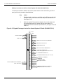
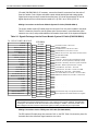
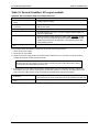
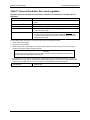
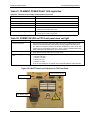
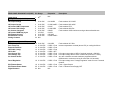
Making Connections via the FPS-System I/O Cable (PN 6388-2884-0)
The FPS–system I/O cable plugs into connector J101 on the FPS. Table 2-4 shows the pinout for
that cable and cross-references signal names to wire colors.
CV-6SLX Technical Manual
2-20
0101-8241-0, Rev. F
Section 2: Installation
2.9 Initial Power Up/Maintenance Power Up Procedure
Table 2-4 Signals Exchanged via the FPS–System I/O Cable (PN 6388-2884-0)
FI LAMENT POWER SUPPLY
(DB -1 5 )
6 3 3 8-2 88 4 -0
J101
BLU
1
GRN
T o p owe r g rou n d
2
T o a n a l og g rou n d
ORG
3
BRN
T o a n a l og g rou n d
4
Ou tpu ts + 2 4 V dc wh e n fi l a me n t i s O K a n d g u n i s on
5
+ 2 4 V dc i n pu t a cti v a te s F i l a me n t B i a s S e t i n pu t
6
+ 2 4 V dc i n pu t e n a b l e s F P S fu n cti on s
7
RED
O u tpu ts + 2 4 V dc w h e n g u n i s e n a b l e d
8
RED/WHT
P rov i d e s +2 4 V dc to e xte rn a l con trol ci rcu i ts
9
BLU/WHT
0 -1 0 V dc ou tpu t ( = 0 to ma x. e m i s s i on cu rre n t re a dou t)
10
11
VIO
11
12
VIO/WHT
0-10 V dc output (=0-50 A on -0 and -1 model FPS units, 0-100 A on -2 FPS units)
12
12
A UT O -B IA S I ND CR H I
13
13
BLK
0-10 V dc input (=0-50 A on -0 and -1 model FPS units, 0-100 A on -2 FPS units)
13
14
14
BLK/WHT
+24 V dc output Auto Bias sequence is complete
G U N IS ON O U T
14
15
15
YELLOW
O u tpu ts + 2 4 V dc w h e n g u n i s on
G UN G O ON IN
15
+ 2 4 V dc i n pu t s wi tch e s on th e g u n
1
CO NT R OL P W R G ND
1
R E QU E S T S I G NA LS CO M
2
2
M O N I T OR S IG N AL S C OM
3
3
F IL O K + G UN IS ON
F IL B IA S S E T S E LE CT
4
5
4
5
BRN/WHT
G UN E N AB LE
6
6
ORG/WHT
G U N I S R E A DY O U T
7
7
C ON T R OL D C P W R + 2 4 V
8
8
E M IS S I ON M ON IT OR OU T
9
10
9
10
11
F I LA M EN T B IAS S E T I N
E M I S S I O N R E Q UE S T I N
F I LAM E N T CU R R E N T M O N
SHELL
2.9
GRN/WHT
SHIELD
0 -1 0 V dc i n pu t ( = 0 to ma x. e m i s s i on cu rre n t re qu e s t)
SHELL
Initial Power Up/Maintenance Power Up Procedure
Follow the procedure described below when powering up the unit for the first time and
whenever it has been powered down and lock/tagged out at the facility breaker (e.g., for
maintenance).
Step
1
Action
Remove the lockout/tagout device from the facility circuit breaker
supplying power to the CV-6SLX.
2
Set the facility breaker switch to the ON position.
3
Set the circuit breaker switch (labeled AC MAINS) on the power
module front panel to the ON position.
4
Set the FPS ON/OFF switch (see Figure 2-6) to the ON position.
Follow the normal operating instructions to switch on and control the HV, the filament bias
current, and the emission current. For operating instructions for standard units, see section 3.5.
For operating instructions for units without a remote gun controller, see section 3.6.
0101-8241-0, Rev. F
2-21
CV-6SLX Technical Manual
2.9 Initial Power Up/Maintenance Power Up Procedure
CV-6SLX Technical Manual
Section 2: Installation
2-22
0101-8241-0, Rev. F
3
Power Supply Operation
3.1
Section Overview
This section covers the following topics:
Section
Section
Section
Section
Section
Section
3.2: Power Module Controls and Indicators
3.3 Switches and Indicators on Filament Power Supply Front Panel
3.4 Control and Display Features on Remote Gun Controller
3.5: Normal Power Supply Operation: Standard Units
3.6: Normal Power Supply Operation: Units Without the Remote Gun Controller
3.7: Responding to Out Of Regulation Conditions and Power Supply Faults
Sections 3.2 through 3.5 and section 3.7 apply to standard CV-6SLX units. Sections 3.2, 3.3, 3.6,
and 3.7 apply to units without a remote gun controller.
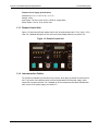
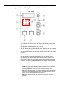
3.2
Power Module Controls and Indicators
Figure 3-1 shows the controls and indicators on the front panel of the CV-6SLX power module.
Those features are described in detail below.
Figure 3-1: Power Module Front Panel
KV Adjustment Pot
High Voltage
Meter
Emission
Current Meter
HV OFF
Button
Status and Fault
Indicator LEDs
Main Power
Breaker
0101-8241-0, Rev. F
3-1
CV-6SLX Technical Manual
3.2 Power Module Controls and Indicators
Section 3: Power Supply Operation
3.2.1 Front Panel Controls
Main Circuit Breaker Switch (Labeled AC MAINS)
High-Voltage Adjustment Pot (labeled Output kV Adjust)
HV OFF Button
3.2.2 Front Panel Indicators
Display Meters
Output Voltage meter (0–10 kV)
• Emission Current meter (0–600 mA)
•
Status LEDs
•
•
•
•
•
•
Power ON LED
HV ON LED
Interlocks OK LED. External interlocks (including power supply covers) are satisfied.
Power Supply Fault LED. Turns red when one or more of the following latching faults has
occurred:
- Rail Undervoltage
- HV Overcurrent
- HV Overvoltage
- Setpoint Overvoltage
- Output Arcing
- Inverter Overload
- Overtemperature
- Aux Supply Low
- External Control Fault
Arc/Out of Regulation LED. Flashes yellow when arcs occur and when the HV is
momentarily out of regulation for any other reason.
Filament Power LED. Filament power supply is powered up.
Fault Indicator LEDs
The following LEDs indicate latching faults, which necessitate the application of the Reset signal
before the power supply can be restarted. Unless otherwise noted, all of these LEDs turn red
when the fault condition in question occurs.
•
•
•
•
•
•
•
•
•
•
•
Rail Undervoltage LED. Inverter rail voltage is below 80% of nominal (range = 540 V to
565 V).
HV Overcurrent LED. HV output current is more than 105% of its maximum (= 600 mA).
HV Overvoltage LED. HV output voltage is more than 105% of its maximum (= 10 kV).
Setpoint Overvoltage LED. HV output voltage is more than 105% of its setpoint value.
Output Arcing LED. Arc rate exceeds 200 arcs/sec., or continuous arcing persists for more
than 120 sec.
HV Out of Regulation LED. HV circuit out of regulation for more than 2 seconds.
Inverter Overload LED. Inverter current exceeds maximum allowable (= 100 A).
Overtemperature LED. Inverter temperature above 67° C, or cooling fan failure.
Aux Supply Low LED. Nominal ±24 V dc control voltage is below 19.5 V dc.
Filament Load Fault LED. Open circuit in filament load (= filament broken or burnt out).
External Control Fault LED. Short circuit in 24 V dc supplied by filament power supply for
external interlock string.
CV-6SLX Technical Manual
3-2
0101-8241-0, Rev. F
Section 3: Power Supply Operation
3.3
3.3 Switches and Indicators on Filament Power Supply Front Panel
Switches and Indicators on Filament Power Supply Front Panel
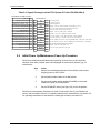
Figure 3-2 shows the switches and LED indicators on the FPS front panel.
Figure 3-2 Filament Power Supply Front Panel
HIGH VOLTAGE ON LED
Emission Current
Selection Switch
POWER ON LED
Power ON/OFF Switch
The switches and indicators on the FPS front panel are:
3.4
•
Power ON/Off switch: Must be switched ON in order for unit to operate.
•
POWER ON LED: When lit, indicates that unit is being supplied with input power.
•
HIGH VOLTAGE ON LED: When lit, both the power module and the FPS indicate that the HV
is on. For further details, see Table 5-13.
•
Emission current selection switch: A black plastic cap normally covers this switch, which is
factory set for the power supply with which it is supplied and should require no further
attention. Figure 3-2 shows the switch set to the 300-mA position. For a standard CV-6SLX
power supply (i.e., with the remote control unit), it should always be set to the 600 mA
position. For CV-6SLX without the remote control unit, it should be set to 1000 mA.
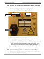
Control and Display Features on Remote Gun Controller
Figure 3-3 shows the remote HV/gun control unit. Control/display features on the HV Control
panel are described in detail below the illustration.
0101-8241-0, Rev. F
3-3
CV-6SLX Technical Manual
3.4 Control and Display Features on Remote Gun Controller
Section 3: Power Supply Operation
Figure 3-3 Remote Control Unit
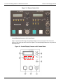
Control/Display Features on HV Control Panel
Figure 3-4 shows the following control/display features on the front panel of the HV Control
portion of the single gun control unit’s front panel. The control/display features on this panel are
described below.
Figure 3-4 Control/Display Features on HV Control Panel
CV-6SLX Technical Manual
3-4
0101-8241-0, Rev. F
Section 3: Power Supply Operation
3.4 Control and Display Features on Remote Gun Controller
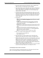
1. Key switch: Must be turned to the ON position in order to enable the HV.
When key switch is in the OFF position, the HV is disabled.
2. High voltage ON button and HV ON indicator light: When the HV Ready light
inside the High Voltage OFF is illuminated, pressing this button switches on
the high voltage. When the high voltage is on, the HV ON indicator light
inside this button is illuminated.
3. HV OFF/HV Reset button and HV Ready indicator light: When the HV is ON,
pressing this button switches off and resets the high voltage. When the HV is
off and the HV interlock chain is made, the HV Ready light inside this button
is illuminated. Pressing this button when both conditions are true switches
the high voltage ON.
4. LED Indicators:
• REG LED: Illuminated when HV circuit is out of regulation for more than 2
seconds; mimics the HV Out of Regulation LED on the power module’s
front panel.
• POWER LED: Illuminated when all dc power supplies are operating
correctly; mimics the operation of the Aux Supply Low LED on the
power module’s front panel.
• DOORS LED: Illuminated when the interlocks for power module and FPS
covers and any customer-defined and supplied external interlocks are all
made.
• FAULT LED: Illuminated when any latching power module (i.e., HVrelated) fault occurs; mimics the operation of the Power Supply Fault
LED on the power module’s front panel.
• REM LED: Illuminated when REM-LOC switch is set to REM.
5. Meter: This 3.5-digit LCD meter displays either of two readouts:
• Power supply total current (0-600 mA)
• High voltage (0-10.0 kV)
6. Meter select switch: This switch enables the user to select either high
voltage and power supply total current for display on the adjacent meter.
7. REMote-LOCal switch: When this switch is in the LOCal position, the user can
adjust the HV manually from the HV control panel. When this switch is in the
REMote position, the HV request is controlled either by a remote input,
usually from a control system, or via the OUTPUT kV ADJUST pot on the
power module front panel. The HV ON and HVOFF buttons are always active,
regardless of the position of the REM-LOCAL switch.
8. HV ADJ pot: When the REM-LOC switch is set to LOC, this 3-turn pot enables
the user to set the high voltage level. It is normally set to 10 kV.
Control/Display Features on Gun Control Panel
Figure 3-5 shows the following control/display features on the front panel of the Gun Control
panel. The control/display features on that panel are described below.
0101-8241-0, Rev. F
3-5
CV-6SLX Technical Manual
3.4 Control and Display Features on Remote Gun Controller
Section 3: Power Supply Operation
Figure 3-5 Control/Display Features on Gun Control Panel
1. Gun ON button and Gun ON indicator light: When the Gun Ready indicator
light inside the Gun Control panel’s OFF button is illuminated, pressing the
Gun ON button switches on the gun. The Gun ON indicator light inside the
Gun ON button is illuminated when the gun is on.
2. Gun OFF button and Gun Ready indicator light: When the gun is on, pressing
this button switches it off. When the gun is off and the TANK, VAC, AUX, and
H20 interlock LEDs are lit, the Gun Ready indicator light inside the this button
is also lit.
3. REMote-LOCAL selector switch: When this switch is in the LOCAL position,
the user can set the emission current request and bias current request
manual via the Gun Control panel. When the REM-LOCAL switch is set to
REM, these functions are controlled by remote inputs, normally from a host
computer. The GUN ON and GUN OFF buttons are always active, regardless
of the position of the REM-LOCAL switch.
4. Indicator LEDs:
• TANK LED: Illuminated when the customer-supplied input for the TANK
interlock is closed. If the Tank interlock is open, none of the other
interlock LEDs will be lit, as Tank is the first in the interlock series.
• VAC LED: Illuminated when the customer-supplied input for the Vacuum
interlock is closed. If this interlock is open, the LEDS for the H20, POS (if
used), and AUX (if used) interlocks will not be lit.
• REM LED: Illuminated when the REM-LOCAL switch is in the REM
position.
CV-6SLX Technical Manual
3-6
0101-8241-0, Rev. F
Section 3: Power Supply Operation
3.5 Routine Power Supply Operation on Standard Units
• H20 LED: Illuminated when the customer-supplied input for the H20
interlock is closed, indicating that cooling water is flowing to the e-beam
source. If this interlock is open, neither the POS nor the AUX interlock
LED will be lit.
• POS LED: A contact closure designed to be supplied by a beam sweep
controller. The position interlock should be closed when the position of
the beam is within the limits preset on the optional beam sweep
controller.
• AUX LED: The auxiliary interlock is a customer-supplied contact closure.
If the contact is open, none of the interlock LEDs that follow will be
illuminated.
5. Meter: Displays either emission current (0-600 mA) or filament current (0-75
A), depending on the position of the adjacent EMI I/FIL I/POS switch.
6. EMI I/FIL I/POS switch: Position of this switch determines whether the Gun
Control panel’s meter displays emission current or filament current.
NOTE
The Gun Control meter displays nothing when the EMI I/FIL I/POS switch is in the POS position, as
position control is not implemented on the CV-6SLX.
7. BIAS control: If the Gun Control panel’s LOC-REM switch is set to LOCAL,
adjusting this pot varies the filament bias current (0-50 A on units with FPS
PN 0620-6604-0; 0-100A on units with FPS PN 0620-6604-2).
8. POSIITON dial: Not implemented
9. EMISSION CURRENT dial: When the gun and the high voltage are both ON
and when this panel’s LOCAL-REMote switch is set to LOCAL, this dial
enables the user to adjust the emission current. When the high voltage is on,
the impedance of the load is determined by the filament temperature.
3.5
Routine Power Supply Operation on Standard Units
3.5.1 Switching Main Power On/Off
To switch on three-phase input power to the power module, set the front panel’s main power
breaker (labeled AC MAINS) to the ON position (i.e., all the way up). To switch off main input
power, set that breaker to the OFF position (i.e., all the way down).
NOTE
The main power breaker on the power module front panel also controls power to the filament power
supply (FPS) module.
3.5.2 High Voltage Control
Switching on the High Voltage
If the power module’s main breaker switch is in the ON position, and if, immediately previously,
you have not switched off the high voltage by pressing the HV OFF button on the power module
front panel, you can switch on the high voltage by performing these steps:
0101-8241-0, Rev. F
3-7
CV-6SLX Technical Manual
3.5 Routine Power Supply Operation on Standard Units
Section 3: Power Supply Operation
Step
1
Action
If the keyswitch on the HV control panel (see Figure 3-4) is not in the
ON position, turn it to that position. The HV Ready light inside the HV
control panel’s OFF button should then light.
2
If the HV Ready light is lit, press the HV control panel’s ON button to
switch on the high voltage.
Switching off the high voltage by pressing HV OFF button on the power module front panel
triggers a latching Power Supply fault. In that event, or if a latching Power Supply fault has
occurred for any other reason, you must perform the following procedure to switch on the HV.
Step
1
Action
Press the HV OFF button on the power module front panel again.
When the HV is off, pressing that button asserts the RESET signal.
2
If the keyswitch on the HV control panel (see Figure 3-4) is not in the
ON position, turn it to that position. The HV Ready light inside the HV
control panel’s OFF button should then light.
3
If the HV Ready light is lit, press the HV control panel’s ON button to
switch on the high voltage.
Adjusting the High Voltage
The high voltage can be adjusted in either of two ways, depending on whether the REM/LOC
switch on the HV control panel is in the REMote or the LOCal position:
1. Switch in LOCal position: Using a flat-bladed screwdriver, turn the H.V. ADJ pot.
2. Switch in REMote position: Vary the REMOTE HV REQUEST signal, which is supplied via G1J2
Pins 18 and 19 on the remote gun controller’s rear panel (see Figure 2-15).
Switching Off the High Voltage
The high voltage is automatically switched off if:
•
any internal or external interlock is no longer made
•
the power supply goes into an latched HV Out Of Regulation state
•
a latching Power Supply Fault occurs.
The high voltage can be intentionally switched off in any of the following ways:
1. The control system can assert the HV GO OFF signal, which is supplied via at HVJ2 Pins 3
and 7 on the remote gun controller’s rear panel (see Figure 2-15).
2. The operator can press the HV OFF button on the power module front panel.
3. The operator can press the OFF button on the HV control panel (see Figure 3-4).
4. The operator can turn the HV control panel’s key switch to the OFF position.
CV-6SLX Technical Manual
3-8
0101-8241-0, Rev. F
Section 3: Power Supply Operation
3.5 Routine Power Supply Operation on Standard Units
3.5.3 Switching the Filament Current On/Off
NOTE
In order for the filament current to be switched on, the FPS module’s power cable must be properly
connected to a source of 220-V ac power, and the module’s ON/OFF switch must be in the ON position.
Switching On the Filament Current
The operator can switch on the filament current by pressing the ON button on the Gun Control
panel (see Figure 3-5) and holding it down for 2 seconds. Alternatively, the control system can
switch on the filament current by asserting the REMOTE GUN GO ON signal for 2 seconds. The
REMOTE GUN GO ON signal is supplied via G1J2 Pins 7 and 8 on the remote gun controller’s
rear panel (see Figure 2-16).
NOTE
Once the HV and the gun are both switched on, the emission current will ramp up to requested level
after a 10–15 second delay.
Switching Off the Filament Current
The operator can switch off the filament current by simply pressing the OFF button on the gun
control panel (see Figure 3-5). The control system can also switch off he filament current by
momentarily de-asserting the REMOTE GUN GO OFF*/ENABLE signal, which is supplied via G1J2
Pins 5 and 6 (see Figure 2-16).
3.5.4 Adjusting the Filament Bias Current and the Emission Current
Adjusting the Filament Bias Current
The filament bias current can be adjusted in either of two ways:
1. The operator can adjust the BIAS pot on the gun control unit’s front panel (see Figure 3-5),
or
2. The externally supplied FILAMENT BIAS SET signal can be varied. That signal is supplied via
Pins 26 and 27 on remote gun controller rear-panel connector G1J2 (see Figure 2-16).
Adjusting the Emission Current
The emission current can also be adjusted in either of two ways:
1. The operator can adjust the EMISSION CURRENT dial on the gun control unit’s front panel
(see Figure 3-5), or
2. The externally supplied REMOTE EMISSION REQUEST signal can be varied. That signal is
supplied via G1J2 Pins 26 and 27 on the remote gun controller’s rear panel (see Figure 2-16).
0101-8241-0, Rev. F
3-9
CV-6SLX Technical Manual
3.6 Routine Power Supply Operation on Units Without a Remote Gun Controller
3.6
Section 3: Power Supply Operation
Routine Power Supply Operation on Units Without a Remote
Gun Controller
3.6.1 Switching Main Power On/Off
To switch on three-phase input power to the power module, set the front-panel’s main power
breaker to the ON position (i.e., all the way up). To switch off main input power, set the main
power breaker to the OFF position (i.e., all the way down).
NOTE
The main power breaker on the power module front panel controls power to the filament power supply
(FPS) module. Switching the HV On/OFF and Adjusting the HV Level
3.6.2 High Voltage Control
Switching On the High Voltage Under Normal Operating Conditions
The control system can switch on the high voltage by asserting the HV GO ON signal (15–24 V
dc) for two seconds at Pin 8 of power module rear panel connector J4 (see Table 2-3).
Switching On the High Voltage Following a Latching Fault Condition
Switching off the HV by pressing the HV OFF button on the power module front panel triggers a
latching Power Supply Fault. In that event, or when any other latching fault has occurred, the
following signals must supplied, in the order given below, to switch the HV back on.
NOTE
If a Power Supply fault has occurred because of a latching fault condition—and not because the user
has pressed the power module’s HV OFF button—the underlying fault that triggered the latching fault
must be corrected before the HV can be reset. For detailed troubleshooting instructions, see Section 5.2.
1. The RESET signal must be supplied. This can be accomplished in either of two ways. Either
the operator can press the HV OFF button, or the control system can assert the RESET signal
at Pins 8-9 of power module rear panel connector J4(see Table 2-3). If the RESET attempt is
successful, all status and interlock LEDs on the power module should be green, except for HV
ON.
2. If the reset attempt has been successful, the control system must assert the HV GO ON
signal at Pin 8 of power module rear panel connector J4.
If this sequence of operations fails to restart the HV, further troubleshooting will be required to
clear the underlying fault condition.
Adjusting the High Voltage Level
The HV level is adjusted by varying the external kV SET IN signal (0–10 V dc = 0–10 kV), which
is supplied via Pin 1 of power module rear panel connector J4 (see Table 2-3).
CV-6SLX Technical Manual
3-10
0101-8241-0, Rev. F
Section 3: Power Supply Operation
3.6 Routine Power Supply Operation on Units Without a Remote Gun Controller
Switching Off the High Voltage
The high voltage is automatically switched off if:
•
any internal or external interlock is no longer made
•
the power supply goes into an HV Out Of Regulation state
•
a latching Power Supply Fault occurs
The high voltage can be switched off by the control system in either of two ways:
3. The control system can momentarily de-assert the HV GO ON signal supplied via Pins 8-9 of
power module rear panel connector J4 (see Table 2-3).
4. The control system can assert the HV GO OFF signal supplied via Pins 17-18 of power module
rear panel connector J4.
3.6.3 Switching the Filament Current On/Off
NOTE
In order for the filament current to be switched on, the FPS module’s power cable must be properly
connected to a source of 220-V ac power, and the module’s ON/OFF switch must be in the ON position.
Switching On the Filament Current
The gun (i.e., filament current) can be switched on only by an externally supplied GUN GO ON
signal, which must be applied via Pin 15 of FPS front panel connector J101 (see Table 2-4).
NOTE
Once HV and gun are both switched on, emission current will ramp up to requested level after a 10–15
second delay.
Switching Off the Filament Current
The filament current can be switched off only by de-asserting the GUN GO ON IN signal, which
is supplied via Pin 15 of FPS front panel connector J101 (see Table 2-4).
3.6.4 Adjusting the Filament Bias Current and the Emission Current
Adjusting the Filament Bias Current
On units without a remote gun controller, the bias current can be adjusted only by varying the
FILAMENT BIAS SET IN signal, which is supplied Pin 12 on the FPS front panel connector J101
(see Table 2-4).
NOTE
When the FIL BIAS SET SELECT signal (supplied via J101 Pin 5) is low, the Autobias circuit of the FPS
controls the bias current. When the FIL BIAS SET SELECT signal is high, the operator can control the
bias current from the control system’s user interface.
0101-8241-0, Rev. F
3-11
CV-6SLX Technical Manual
3.7 Responding to Out of Regulation Conditions and Power Supply Faults
Section 3: Power Supply Operation
Adjusting the Emission Current
On units without a remote gun controller, the emission current can be adjusted only by varying
the EMISSION REQUEST IN signal, which is supplied via Pin 10 FPS rear panel connector J101
(see Table 2-4).
3.7
Responding to Out of Regulation Conditions and Power Supply
Faults
During normal operation, the Out of Regulation LED on the power module front panel will flash
intermittently as arcs occur. The flashing will increase in frequency as arcs increase in
frequency. If arcs become too frequent are persist at too high a rate for too long, the internal
OUT OF REGULATION is asserted, latching off the HV and triggering a Power Supply fault. The
Out of Regulation LED will then glow steadily.
To switch the HV back on when a the power supply is in an Out Of Regulation state, or when a
latching Power Supply fault has been triggered by any other condition, the RESET signal and the
HV ON signal must be asserted, in that order. On standard units, the operator can simply press
the HV OFF button (which supplies the RESET signal when the HV is off) and then press the ON
button on the HV control unit’s front panel (see Figure 3-4). On units without a remote gun
controller, the following signals must be supplied in order for the HV to be switched on when a
latching Power Supply fault has occurred:
•
the RESET signal, supplied via Pins 10 and 11 on power module rear panel connector J4
•
the HV ON signal, supplied via Pins 8 and 9 on the same connector.
If the Out of Regulation condition occurred because of intermittent arcing, the HV should come
back on. The same applies to Power Supply faults that occur because the operator has switched
off the high voltage by pressing the HV OFF button on the power module front panel. In the
case of an Out Of Regulation state triggered from a dead short, it will be necessary to identify
and eliminate the source of the short, which may be due to a flake in the vacuum chamber or to
a defect or fault in the HV circuit. Power Supply faults triggered by latching faults other than Out
Of Regulation will also require troubleshooting. For troubleshooting instructions covering these
cases, see Section 5.
CV-6SLX Technical Manual
3-12
0101-8241-0, Rev. F
4
Theory of Operation
4.1
Section Overview
This section provides separate theories of operations for the major modules of the CV-6SLX
power supply. Section 4.2 contains a theory of operation for the power module, and section 4.3
covers the FPS in detail.
4.2
Power Module Theory of Operations
4.2.1 Top Level Theory
Several physical and functional assemblies form the HVPS. Referring to the top-level schematic
(Figure 6.1 above), AC line power is connected to the HVPS through terminal block TB1. Line
filter LF1 then creates high frequency filtering to minimize conductive emissions from the unit,
as well as provides immunity to common levels of AC line transients. The load side of the line
filter then feeds three-phase circuit breaker CB1, as well as auxiliary filtered IEC outlet J2. This
AC connector is fused at 6.3A by F1 and F2, which are accessible on the rear panel through
panel-mounted fuse holders. The IEC outlet is sourced differently, depending on the unit’s line
voltage range: the 208VAC unit connects the IEC outlet between phases, while the 400VAC unit
connects it between a phase and neutral. This is intended to maintain the IEC outlet voltage
between 187VAC and 254VAC, considering the ±10% tolerance of voltages applied to TB1.
Grounding to the unit is provided through two external fasteners. One threaded stud in the
lower center of the rear panel must be connected to an earth ground for safety. Another
threaded stud on the rear panel, near HV output connector J1 and labeled “RF GND”, provides a
ground return for the HV output. Internally, ground wires are connected together with a ground
“block”, mounted to the bottom panel.
Mounted to the front panel and shielded from inadvertent operation by a “kick” guard, circuit
breaker CB1 provides over-current protection of the three AC line phases. The load side of the
circuit breaker feeds Inverter board A1, whose functions are discussed in a section below.
Several other components and assemblies connect to the Inverter.
0101-8241-0, Rev. F
4-1
CV-6SLX Technical Manual
4.2 Power Module Theory of Operations
Section 4: Theory of Operation
Two AC line phases from the Inverter feed the primary of step-down transformer T2 (wired with
jumpers for a 1:1 ratio in the 208VAC unit and 2:1 ratio in the 400VAC unit), which in turn
powers the AC input of +24VDC auxiliary power supply PS1. The +24VDC output of PS1
connects back to the Inverter, and provides low voltage power to the other board assemblies in
the HVPS.
Temperature inputs come from two separate devices connected to the Inverter, thermostat S2
and IC sensor U1. S2 opens when the Inverter heat sink rises above a preset temperature,
while U1 generates an analog voltage scaled to the temperature of the heat sink near the
Inverter IGBTs. Both sensors feed the over-temperature fault circuitry. Cooling of internal
components is provided by +24VDC fan B1 mounted on the rear panel, which draws airflow in
through the front panel grille, and exhausts at the rear. An integrated jammed rotor sensor in
the fan senses when the blades have stopped spinning, and will trip an over-temperature fault.
After the circuit breaker, the three AC line phases are fed to the Inverter for conversion from
50/60Hz AC power into high frequency power. Part of the conversion process involves rectifying
the AC input voltage through a three-phase bridge rectifier and current smoothing with “DC link”
choke L1. This inductor improves the power factor of the HVPS as seen by the AC power grid.
High speed IGBTs in the Inverter switch the rectified bus voltage through HV Transformer T1 at
25kHz, thereby converting the intermediate DC power once again into AC power. HV Rectifier
board A2 then converts the high frequency, high voltage output of the HV Transformer into DC
high voltage power. In addition, the HV Rectifier scales the output voltage and current for
feedback to the Regulator control circuits. DC output voltage is delivered from this board to the
external load through custom high voltage “cablewell” connector J1. The mating connector and
cable for J1 is provided with each HVPS.
Virtually all logic, control, and analog processing functions are managed on Regulator board A3.
To provide visual indications on the front panel, Display and Control board A4 is connected and
sandwiched between the front panel and the Regulator. In addition, the Display and Control
board provides an HV OFF pushbutton, output voltage adjustment potentiometer, and voltage
and current LCD displays for the user. The Regulator links with the customer’s remote interface
through the three D-subminiature connectors on Interface board A5, which is mounted to the
upper left corner of the rear panel. The most critical function of the Regulator is to compare the
output feedback to the provided references and then feed the Inverter IGBT gate drives to
properly actuate them.
4.2.2 Module Level Theory
A1 Inverter
Two versions of the Inverter board (P/N 9150035-014 and 9150035-012) are used in the
208VAC and 400VAC units, respectively, however they are virtually identical. The three AC line
phases are fed to the Inverter board through three pins of J32, which is a Molex Mini-Fit Sr.
series connector. Two phases of the AC are distributed to the primary of the step-down
transformer through slow-blow AC fuses F1 and F2, which protect the transformer from overcurrent (1A for the 208VAC unit, and ½A for the 400VAC). J24 connects the fuses to the
transformer.
CV-6SLX Technical Manual
4-2
0101-8241-0, Rev. F
Section 4: Theory of Operation
4.2 Power Module Theory of Operations
Rail Capacitor Charging
To limit AC inrush current during charging of the rail capacitors, thermistors R97 and R129 act
as a series resistance between the AC line and the bridge rectifier. At high line, the peak inrush
current is approximately 16A for both AC input voltage units. The rail capacitors are charged to
97% of their final voltage level through these thermistors and two phases of the three-phase
bridge rectifier formed by CR17, 23, and 28 before the +24VDC auxiliary power supply starts
delivering its output. Once the +24VDC supply has energized and the rail voltage exceeds its
minimum value (as determined on the Regulator board: 220VDC and 430VDC for the 208VAC
and 400VAC units, respectively), three-phase relay K1 is activated through J31 (and a
connecting cable to J3) by signal AC_RLY_ON from the Regulator.
With the contacts of relay K1 closed, all three phase currents are rectified by CR17, 23, and 28
and somewhat filtered for high frequency noise by C64 and C61. The resulting DC-biased
current passes through high-speed fuse F3, which protects downstream components from overcurrent (40A for the 208VAC unit, and 20A for the 400VAC). AC power factor is passively
improved with the DC link choke (1.2mH for the 208VAC unit, and 4.8mH for the 400VAC),
which connects to the Inverter through J25. Two extra pins on J25 are used for the additional
current in the 208VAC unit. The last constituent of the Inverter rail is formed by bulk electrolytic
capacitors C46-57 (arranged in a series-parallel matrix). The series capacitor banks are voltagebalanced by R65, 67, 68, and 71, which also serve as discharge resistors when power is
removed from the unit. It is important to note that circuit nodes on the schematic connected to
the symbol used for the negative side of the Inverter, “ground” with a ‘C’ attached to it ( ),
are floating at a high voltage with respect to ground, and should never be connected to
anything earth/ground referenced. Schematic symbol ( ) is also connected to this floating
node, and should never be connected to earth/ground as well.
Full Bridge IGBT Inverter
IGBTs Q6, 7, 10, and 11 form the “heart” of the Inverter, switching on-and-off at 25kHz to drive
current through the primary of the HV Transformer. The IGBTs are arranged in a full-bridge
configuration, and are controlled in a phase-shifted scheme, whereby Q7 and Q11 are always in
an opposite conducting state from each other (i.e. one is on while the other is off), as are Q6
and Q10 always in an opposite state. By shifting the phase between these two pairs of IGBTs,
the effective current-on time delivered to the HV Transformer can be varied precisely. The IGBT
switching sequence generated by the phase-shift modulated (PSM) controller chip on the
Regulator is connected through J11 (which contains other control signals as well) to the
Inverter. Driver chips U7 and U8 transmit those signals to the gates of the IGBTs through DC
coupling capacitors C35 and C36, and gate drive transformers T1 and T2 (which have a 1:1:1
transfer ratio). Separate turn-on and turn-off gate resistor pairs are employed (to limit EMI and
turn-off losses, respectively), as well as high frequency series ferrite beads to limit ringing on
the gates. Each IGBT possesses an “RCD” (resistor, capacitor, and diode) snubber circuit
between its collector and emitter leads (e.g. R41, C43, and CR6). This snubber circuit limits the
collector voltage overshoot during turn-off and protects the IGBT from damage.
High frequency current from the rail capacitors passes through the input terminals of Hall-effect
current sensor U15, through the half-bridge IGBTs, through resonant capacitor C2, and out to
0101-8241-0, Rev. F
4-3
CV-6SLX Technical Manual
4.2 Power Module Theory of Operations
Section 4: Theory of Operation
the HV Transformer primary through J8. Capacitor C2 and the leakage inductance of the HV
Transformer form part of a resonant tank that allows zero current switching (ZCS) of the IGBTs
under most conditions. ZCS reduces power dissipation in the IGBTs, and lowers EMI from the
Inverter. The output and supply terminals of current sensor U15 link back to the Inverter
through a connecting cable to J1, and are electrically isolated from the input terminals and the
IGBT current. U15 has a 75:1 current-to-voltage transfer ratio on its output terminal, which is
buffered by op amp gate U3:C. This buffered representative signal of the IGBT current is sent
directly to the Regulator on J11, and is also compared to +1.24V by U9 after going through an
RC low pass filter with a gain of approximately 0.8 at 25kHz. When the signal exceeds +1.24V
(approximately 116A peak), U9 pulls the SET pin of U10:B to ground, thereby latching its output
high. This signal, RAIL_FAULT, gets passed to the Regulator on J11, and triggers an Inverter
Overload indicator.
Temperature Sensing
Two temperature measuring devices are connected to the Inverter, a thermostat switch
(connected to J2) and an active temperature sensor (connected to J6). The thermostat switch
contacts remain closed as long as the temperature of the Inverter heat sink where it is mounted
stays below 77°C, but open when that trip point is exceeded. When the contacts are open the
SET pin of U10:C falls to ground, thereby latching its output high. This signal, THERMO_FAULT,
gets passed to the Regulator on J11, and triggers an Overtemperature indicator. All latches on
the Inverter board are reset by the Regulator through signal RESET* on J11. The active
temperature sensor is also mounted to the Inverter heat sink, but is closer to the IGBTs and
produces a linearly scaled output voltage relative to its temperature (10mV/°C). This analog
temperature signal, TEMP_OUT, is passed directly to the Regulator for processing.
Auxiliary Power and Rail Voltage Monitor
Auxiliary +24VDC power is fed to the Inverter board on J5 as power signal AUX_24, which
(along with being passed directly to the Regulator) then powers two items, the +24V bus
through CR2 and the DC fan through low-pass filter L1 and C20 to J4. If the rotor of the fan
becomes jammed, its alarm output on J4 is sent to the Regulator and triggers an
Overtemperature indicator. The +24V bus is connected back to the Regulator on J11, and also
powers +24V-to-±15V DC-DC converter U1. This isolated ±15V supply powers the rail voltage
sense circuitry. Since the Inverter rail is not ground referenced, and floats several hundred volts
from it, some form of isolation barrier is needed to scale and convert the rail voltage magnitude
to the ground referenced Regulator. R157-165, R176, and C96 form a filtered 89:1 voltage
divider network across the rail, which feeds an analog isolation circuit. This circuit, powered by
the ±15V from U1, employs a filtered control amplifier (U4) that drives a high linearity
optocoupler (U2) configured to compensate for temperature and age-related optocoupler drift.
The isolated output of the optocoupler is amplified by U3 and scaled by potentiometer R2 for a
final 100:1 ratio of rail voltage to signal output, which is routed to the Regulator on J11. Several
of the signals on J11 are not connected on these versions of the Inverter board, and have no
functionality despite their node names: pins 11, 12, 13, 14, 16, 18, and 22.
CV-6SLX Technical Manual
4-4
0101-8241-0, Rev. F
Section 4: Theory of Operation
4.2 Power Module Theory of Operations
A2 HV Output
Secondary Tuning
High frequency AC voltage driven on the primary of the HV Transformer by the Inverter is
transformed by a fixed ratio (15:225), and connected to the input of the HV Output board (P/N
9170079-012) at J1 and J2. Since the AC high voltage magnitude on J1 will be at least two times
as large as that on J2 (with reference to ground), and the “finish” winding lead of the HV
Transformer has more spacing to ground than the “start” lead, J1 must always be connected to
the “finish” lead. Between J1 and J2, effectively across the HV Transformer secondary, is the
“secondary tuning” capacitance. This capacitor bank, formed by C31-35 and C41-45, creates a
series-parallel resonant circuit with the primary leakage inductance of the HV Transformer. The
resonant circuit both smoothes HV Transformer primary current wave shapes and enables zero
current switching in the Inverter IGBTs, which reduces EMI and switching losses, respectively.
HV Rectification
A full-wave voltage “doubler” is employed on the HV Output board to produce a rectified output
voltage that is double the peak-to-peak voltage across the HV Transformer secondary winding.
Two series strings of high-speed diodes, CR1-13 and CR14-26, as well as C28 and C29, form this
doubler circuit. Capacitors C1-26 are used to evenly distribute the reverse AC voltage across the
diodes. Each diode is subjected to less than 62% of its rated reverse voltage. High voltage film
capacitor C27 is used as a storage element, reducing the output ripple voltage. High power
wire-wound resistors R9-14 carry all of the output current, and are used to limit the current
delivered from output capacitors C27-29 in the event of a single load arc or time-limited
continuous arcing. The Regulator will actively terminate the HV output before these resistors
overheat from their arc-limiting duty. The final output is connected to the rear panel HV cable
well through J3.
Voltage and Current Feedback
Scaled voltage and current feedback are supplied to the Regulator through connector J5. R1,
C36, and C38 form a frequency compensated voltage feedback network to the Regulator, which
coupled with a low side resistance of approximately 96kΩ on the Regulator, produces an equal
DC and AC voltage division ratio of roughly 200:1. Resistor R6 protects the voltage feedback
capacitors from damage induced during HV output arcing by inherently limiting the arc current
to 0.33A peak. Spark gap E2 protects the Regulator input from over-voltage in the event of a
feedback network component failure. Parallel resistors R2 and R3, along with noise filtering
components R4, R5, and C37, create a voltage signal relative to the current delivered by the HV
Output board to the load. This ratio, 3.75V:1A, provides a voltage signal to the Regulator for
processing. Similarly to E2, E1 protects the Regulator input from over-voltage should a current
feedback component fail.
Chassis ground is solidly connected to the HV Output board through a conductive standoff
attached to the bottom side of the board, which helps reduce noise and “ground bounce” in the
control circuits. Terminal J4 is also connected to this ground “plane”. Pin 6 of J5 is not
connected on this version of the HV Output board, and has no functionality despite its node
name.
0101-8241-0, Rev. F
4-5
CV-6SLX Technical Manual
4.2 Power Module Theory of Operations
Section 4: Theory of Operation
A3 Regulator
kV Feedback and Control
Output voltage control of the HVPS is the primary function of the Regulator, and starts with the
user programming the desired voltage setpoint. This is accomplished either locally or remotely,
via the front panel OUTPUT kV ADJUST potentiometer or a pin on the rear panel J4 HVPS
CONTROL I/O connector (referred to as the User Interface), respectively. These two signals are
brought onto the Regulator through connectors J13 and J1 as signals KV_REF_LCL and
KV_REF_REM, respectively. These reference control signals, scaled for +10VDC = –10kVDC, are
calibrated with potentiometers R114 and R108, and fed to analog switches U35:B and U35:C,
respectively. Only one signal is routed through the analog switches to the reference inverter
amplifier, as determined by the signal LOCAL (where High = +5VDC = Local Mode), which
comes from the User Interface through an isolating optocoupler (U17:A). The now single
calibrated voltage reference signal, KV_REF_CAL, is filtered, scaled, and inverted via op amp
U33:E. The voltage output of U33:E produces a fixed current flow through R194, 207, and 211,
which is fed away from the inverting terminal of voltage error amplifier U30:C, discussed later.
“Shunt” jumper J14 is used during the test process to check the over-voltage fault circuit.
To control the output voltage in a closed loop, the reference signal must be compared to the
feedback signal. The partially divided output voltage signal is brought in from the HV Output
board through pin 4 of J12, and further divided and filtered for noise with R118, R142, R149,
C76, C83, C88, and C89. Potentiometer R118 is also used during test to match the feedback
waveform shape to the actual output waveform shape. Potentiometer R90 and R134 are used
to compensate for the effect of the voltage drop across the arc limiting resistors on the HV
Output board, which add a load current dependent voltage offset. The negative feedback signal
is inverted by op amp U30:B, before being fed to the voltage error amplifier as signal KV_CAL.
This signal creates a current flow through R146 and R156 that is proportional to the HV output
voltage. Error amplifier U30:C varies the Inverter IGBT duty cycle so that its inverting terminal
stays at zero volts, which is the condition when the current flow through R146 and R156 is equal
but opposite to the current flow through R194, 207, and 211. This is how the Regulator
maintains the HV output voltage at the requested setpoint. Components R143, R154, R155,
C90, C96, and C101 form a two-pole and two-zero frequency compensation network, which
ensures that the closed voltage control loop is quick to respond, but is always stable as well.
mA Feedback and Control
The current setpoint, feedback, and error amplifier work in similar ways to their voltage
counterparts. Current setpoint programming is only “received” internally, created by +10VDC
reference chip U22 in conjunction with filtering, inverting, and scaling buffer op amp U33:D.
The reference current fed away from the inverting terminal of current error amplifier U30:D
through R79, 81, and 204 is calibrated by potentiometer R81 to maintain a fixed 0.6ADC HV
output current when the HVPS is in current control mode. Differential amplifier U32:B takes the
current feedback signal from the HV Output board connected across pins 1 and 3 of J12,
through some RC filtering, and scales it with R174 and R132. The scaling equation for the
output pin of U32:B is equal to 1 + {50500/(R174 + R132)}, which allows potentiometer R132
to calibrate the output pin to 6VDC when the HV output current is 0.6ADC. This voltage then
creates a current in R192 and R193 that is equal but opposite to the flow in R79, 81, and 204,
CV-6SLX Technical Manual
4-6
0101-8241-0, Rev. F
Section 4: Theory of Operation
4.2 Power Module Theory of Operations
when current error amplifier U30:D is closing the control loop. Components R180, R193, R203,
C105, C112, and C123 form a two-pole and two-zero frequency compensation network, which is
optimized for output current control.
CR34, CR39, and R160 are configured so that the lower magnitude output between the voltage
and current error amplifiers is connected to the error amplifier bus, signal ERR_AMP, and
enables the HVPS to switch to constant 0.6ADC current control mode only when the voltage
error amplifier can no longer maintain the requested HV output voltage. Test jumper J10 is
used to switch between open and closed loop control modes, which is only utilized during
troubleshooting. Normally the unit is in closed loop mode with the jumper across pins 2 and 3,
but with the jumper across pins 1 and 2 the output voltage is manually controlled with
potentiometer R98.
Phase Shift Modulator
R135 and C73 form a low pass filter on the error amplifier bus to minimize switching noise. A
voltage limiter is created by R125, R133, and U23, which limits the error amplifier bus to
approximately 4.9VDC and protects the input pin of phase shift modulator (PSM) chip, U26. This
chip is also damaged by negative voltages on its pins, so CR26 is used to clamp negative spikes.
The PSM chip creates the correctly timed gate waveforms for the Inverter IGBTs relative to the
level of the error amplifier bus (i.e. increasing bus creates increasing phase shift). The internal
error amplifier in the PSM chip is effectively bypassed by being configured as a voltage follower,
and slightly filtered by C84. Potentiometer R121, R163, and C99 set the PSM chip’s internal
oscillator frequency, which is double the IGBT switching frequency by definition. R121 is
calibrated so that the switching frequency is set for 25kHz. Potentiometer R45, R162, and C98
together set the slope of the comparator voltage ramp, which permits adjusting the maximum
phase shift or effective duty cycle. Currently R45 is set at test for 100% duty cycle. R137 and
R159 set the delays between the C/D and A/B gate drive outputs, respectively, which not only
assures no IGBT cross conduction current, but also enables zero voltage switching (ZVS) of the
IGBTs under certain conditions. The four gate output signals (GATEA, GATEB, GATEC, and
GATED) connect to the Inverter board on J8 through series protections resistors R128-130.
Since the pulse currents on the gate drive outputs can sometimes be large, the PSM chip
employs separate power and ground connections to isolate the drive circuitry from the sensitive
control pins. Drive-related pins VC and PGND are therefore also isolated on the board layout
through R157 and R164, and a separate copper ground plane for PGND, shown symbolically as
.
Analog Monitors
Several analog monitors scale and buffer feedback from other boards and sensors in the unit,
delivering them to the interface connectors and front panel displays. The already buffered HV
output voltage feedback signal is calibrated by R61, buffered by U33:B, current-limited by
resistor R182, fed to the interface connector through J1, and the front panel display through
J13. The HV output current feedback is similarly processed by R72, U33:C, and R183, and fed
out through J1 and J13. The output of the analog Inverter temperature sensor, mounted on the
heat sink near the “warmest” IGBT, is routed in through J8, and then filtered, scaled, and
buffered by U14:B. IGBT_TEMP is linearly scaled from 0 to +10VDC to represent 0 to 160°C.
0101-8241-0, Rev. F
4-7
CV-6SLX Technical Manual
4.2 Power Module Theory of Operations
Section 4: Theory of Operation
This signal is then connected out to the Diagnostics connector through J1, and also fed to
“comparator” U20.
+24VDC control power connected directly to the Auxiliary supply through the Inverter on J8 is
scaled (+10VDC = +24VDC), filtered, and buffered by U16:E, and fed to the Diagnostics
connector (via J1) through current-limiting resistor R77. A square wave signal representing the
effective duty cycle of the PSM chip gate outputs is created by U27:B, which is then averaged,
scaled, and buffered by U16:C to create a signal where +10VDC = 100% effective duty cycle.
This signal is routed to the Diagnostics connector through current-limiting resistor R83 and out
on J1. The isolated and scaled rail voltage signal on J8 from the Inverter is slightly filtered and
buffered by U16:D (so that +10VDC = +1000VDC) to feed to the Diagnostics connector through
current-limiting resistor R93 and out on J1.
Arc Monitoring and Management
High voltage output arcs are detected by comparator U8:B by comparing the buffered output
voltage feedback signal KV_CAL (through jumper J11) to ground. R16 and R27 create a small
positive DC reference (approximately +0.12VDC), which is briefly driven below ground (through
C6) by the steep negative slope of KV_CAL during an output arc. This triggers U8:B to pull its
output low, which pulls the “Arc Bus” low through ORing diode CR10. The “Arc Bus” is also
pulled low by comparator U8:C through CR11 if the Inverter current signal coming through J13
(RAIL_CURR) exceeds the calibrated value set by R20. Sometimes HV arcs reveal themselves by
high currents in the Inverter. When the “Arc Bus” goes low, this triggers the input of one-shot
U18:B, creating a retriggerable 2.21ms long output pulse. The active low-output ( Q ) pulse
creates signal SHUTDOWN*, its inverse SHUTDOWN (through inverter U13:E), and a –14VDC
pulse, SHTDN_NEG, created by U14:C configured as a bipolar output inverter. Signal
SHUTDOWN* turns MOSFET Q14 off, which allows the voltage divider created by R126 and
R136 to apply +3.33VDC to the CS+ (Current Sense) pin of the PSM chip. Since the CS+ pin is
greater than +2.5VDC, the PSM chip immediately disables its gate output pins until the CS+ is
pulled once again to 0VDC by Q14 when SHUTDOWN* goes high after 2.21ms. During this
2.21ms the Inverter IGBTs stop switching and providing power to the HV Rectifier, which allows
the HV arc that started this sequence to clear before the Inverter is reactivated. SHUTDOWN
turns MOSFET Q15 on, which pulls the error amplifier signal to the PSM chip to ground, thereby
initiating another method of Inverter shutdown. SHTDN_NEG activates yet another shutdown
method by turning both Q18 and Q19 on, which short the current and voltage references to
ground, respectively. By requesting no current and no voltage, the Inverter switching is
effectively shut down here too. However, Q18 and Q19 have a secondary function as “soft
starts” since the reference signals will “slowly” charge using R79/C129 and R194/C124,
respectively, over roughly 100µs.
The 2.21ms long active high output (Q) pulse from U18:B (ARC), created by an HV arc, is fed
into the input of frequency-to-voltage converter U1 (an LM2907). (ARC also briefly flashes the
ARC/OUT OF REGULATION LED yellow on the front panel via OR gate U37:E and J13.) U1 uses
a charge pump to create a voltage output (on pins 5 and 10) which is linearly related to the
frequency of the square wave on its input. The values of R2, C1, and C2 have been chosen to
create a frequency-to-voltage equation of V = 0.0199×f, where V is in VDC and f is in Hz. This
signal is scaled and filtered by R19, R59, and C19, and then buffered by U14:D. The buffered
CV-6SLX Technical Manual
4-8
0101-8241-0, Rev. F
Section 4: Theory of Operation
4.2 Power Module Theory of Operations
output can be selected by jumper J3 to be fed to the Diagnostics connector, but this is not
currently the default jumper setting. Prior to the U14:D buffer, the scaled (100:104) and filtered
signal is compared by U8:D to +1.92VDC, created by the divider formed from R40 and R49,
which pulls its output low when the arcing frequency exceeds approximately 100Hz (see
frequency-to-voltage equation above). This turns MOSFET Q16 off, which allows C91 and C92
to start charging to +5VDC through R144 and R147. The charging voltage on these two
capacitors is scaled and buffered by U14:E so that ARC_DUR is equal to +10VDC after 120s,
which assumes the arcing frequency has exceeded 100Hz during all 120s. If the arcing
frequency drops below 100Hz, the capacitors are discharged to ground by Q16, and will start the
charge sequence from 0VDC the next time the frequency exceeds 100Hz. ARC_DUR is fed to
the Diagnostics connector through current-limiting resistor R97 via J3 and J1.
Another outcome of the “Arc Bus” going low is the creation of a retriggerable two-second output
pulse produced by one-shot U39:B. This two-second signal is fed to the Diagnostic connector
via Q28 and J1.
“Out of Regulation” Monitoring
Since there are separate voltage and current error amplifiers, these can be used to determine if
the HVPS is able to regulate its output to the requested voltage setpoint. When the HV output
voltage has not reached (or cannot reach) its given setpoint, the voltage error amplifier will go
to its positive “rail” to try and force the Inverter to its maximum duty cycle. During this
condition, if the Inverter and HV Rectifier can achieve 600mA of output current, the current
error amplifier will be some fixed value, much lower than its positive rail and the “railed” voltage
error amplifier. This will create current through R104 and the emitter diode of U19:A, thereby
turning on the optocoupler’s output transistor and switching OOR high. OOR going high briefly
flashes the ARC/OUT OF REGULATION LED yellow on the front panel via OR gate U37:E and
J13, and it briefly flips its status pin on the Filament Interface connector via Q22 and J1. If this
OOR transition occurs when HV is on, one-shot U21:B will create a retriggerable two second
long output pulse. The active high-output (Q) pulse (OUT_OF_REG) feeds several circuits. Via
J13 it flashes the HV OUT OF REGULATION LED yellow for two seconds to give a visual
indication of the condition. It controls a status pin on the Diagnostics connector via Q10 and J1,
and on the User Interface connector via jumper J17, Q21, and J1.
Power-Up and Manual Resets
When the HVPS is first powered up from the AC line connection, the +15VDC auxiliary supply
line will slowly rise from 0VDC to its final value. Two RC “timers”, formed by R39, R43, R44,
C18, and C27, are compared by U7:E to create a reliable active low reset signal approximately
120ms after the +15VDC supply starts rising. This ensures that all latches, one-shots, and flipflops (from PUP_RST* and RESET*, via Q11 and Q12) are reset properly before they fully power
up. Latches that must be cleared, either manually or automatically, during normal HVPS
operation receive that reset via RESET*. This signal is created from either of two sources. A
manual reset is brought in from the User Interface connector via J1 as two pins (RESET IN+ and
RESET IN–) which require momentary shorting to initiate the reset. When these two pins are
shorted, current flows through the emitter diode of optocoupler U10:B, which turns on its output
transistor and causes the input of one-shot U21:C (through OR gate U5:C) to transition high.
0101-8241-0, Rev. F
4-9
CV-6SLX Technical Manual
4.2 Power Module Theory of Operations
Section 4: Theory of Operation
This creates a retriggerable 100-µs long output pulse which briefly drives RESET* low, and
clears all the latches. This “reset” one-shot is also triggered by an HV Off command, routed
through jumper J16 (which can be moved so that the one-shot triggers from an HV Enable
command) and OR gate U5:C.
HV Enable, On, and Off Commands
Functioning as an HV Enable command, two pins on the User Interface connector (HV ON IN+
and HV ON IN–) are brought in via J1 and require momentary shorting to initiate the enable.
Just like the reset, when these two pins are shorted, current flows through the emitter diode of
optocoupler U10:A, which turns on its output transistor and causes HV_EN_IN to transition high,
originating an HV Enable command. Similarly, for the HV Off command, two pins on the User
Interface connector (HV OFF IN+ and HV OFF IN–) are brought in via J1 and require momentary
opening to initiate the off request. When these two pins are opened, current stops flowing
through the emitter diode of optocoupler U19:B, which turns off its output transistor and causes
HV_OFF_IN* to transition low (HV_OFF_IN transitions high due to inverter gate U13:B),
originating an HV Off command. The HV Off command can also be initiated locally using the
front panel HV OFF pushbutton switch routed onto the Regulator through J13, which
momentarily shorts the input of one-shot U18:C high, activating a retriggerable 470µs long
output pulse. This output pulse turns Q24 on, shorting the anode of optocoupler U19:B to
ground, shunting current away from it and turning its output transistor off momentarily.
The HV Enable command is used to activate the HV On command when several conditions are
met. To begin with, the reset (R) pin of flip-flop U24:B must be low, which requires that the HV
Off command pins on the User Interface connector be shorted (HV_OFF_IN is low) and the Sum
Fault bus signal (SUM_FLT) be low. These two conditions allow the output of OR gate U37:C to
be low. Then, a momentary closure of the User Interface HV ON IN pins creates a rising-edge
trigger on the clock pin of U24:B (HV_EN_IN), latching the high state of HV_OFF_IN* (inverse of
HV_OFF_IN by definition) onto the flip-flop’s Q output pin. Since HV_OFF_IN* is high, and if
SUM_FLT* is high (indicating no faults in the HVPS), HV_ON will also go high since the inputs of
AND gates U27:C and U12:C are all high. With HV_ON high, the output of AND gate U27:D
(SHUTDOWN*) will go high and the PSM chip will allow its gate outputs to start switching (as
discussed in the Arc Monitoring and Management section above). If the Sum Fault bus signal
(SUM_FLT) transitions high, indicating there is a serious fault somewhere in the HVPS, HV_ON
will go low as a result of the input to AND gate U12:C going low (which receives the inverse of
SUM_FLT from inverter gate U13:F). This will immediately terminate the PSM chip’s gate
outputs. In addition, when SUM_FLT transitions high, one-shot U39:C will produce a 100µs wide
output pulse, which resets the flip-flop output to low through OR gate U37:C. Assuming that
either a Reset or HV Off command has been issued to clear the Sum Fault bus, another HV
Enable command is then required to cycle the flip-flop output high again. The HV Off command
will also reset the flip-flop output to low, setting HV_ON low.
The READY signal is high when the SUM_FLT* bus is high (fed through jumper J18 and into one
input of AND gate U12:B, indicating no faults), when the User Interface HV OFF IN pins are
shorted (i.e. HV_OFF_IN* is high, fed into one input of AND gate U27:E), and when HV_EN* is
high (fed into the other input of AND gate U27:E, indicating a User Interface HV Enable
command has not been requested). To prevent the customer’s system from tripping itself off
CV-6SLX Technical Manual
4-10
0101-8241-0, Rev. F
Section 4: Theory of Operation
4.2 Power Module Theory of Operations
prematurely during the duration of an HV Enable command, the HV_EN* signal is OR-ed with
the HV_EN_IN signal by gate U37:B, whose output only goes low after the HV Enable command
has been latched and the User Interface HV ON IN pins have opened again. Status indicators
for READY, HV_ON, and SUM_FLT are created by Q29, Q1/Q30, Q25, Q26, Q27, and Q23, and
sent to the User Interface, Diagnostics, and Filament connectors through J1. HV_ON also turns
the HV ON LED green on the front panel through J13.
Faults
Numerous fault circuits are used to determine if there is a malfunction in the HVPS serious
enough to shut down the HV output. In several of these circuits a compensated shunt voltage
regulator (TL431) with a +2.5VDC reference is used as a 3-pin 2.5V comparator. If the voltage
applied to the reference pin exceeds +2.5VDC, the cathode of the TL431 is pulled to ground
where the anode is connected. This creates a very simple over-limit comparator. All fault
signals are diode “OR-ed” onto the SUM_FLT bus by CR43, 44, and 46-48, which creates a single
high signal indicating at least one HVPS fault is present, and turns the front panel POWER
SUPPLY FAULT LED red through J13.
The buffered kV feedback signal KV_CAL is divided and filtered by R4, R6, R8, and C3, and fed
into the input of TL431 “comparator” U3. R4 is calibrated so that U3 trips latch U11:C when the
output voltage exceeds –10.5kVDC. The latch’s output turns the front panel HV OVERVOLTAGE
LED red through J13 and (via Q7 and J1) pulls the open-collector over-voltage status pin low on
the Diagnostics connector. Feedback signal KV_CAL is also used to trip the reference overvoltage fault. Calibrated voltage reference signal KV_REF_CAL is compared to KV_CAL (divided
by R7 and R14) by U7:C, using R7 to calibrate the circuit to trip when the actual output voltage
exceeds the reference setpoint by 5%. R9, 13, and 214 are used to add an offset voltage to
KV_REF_CAL so that U7:C is not forced to compare two +0VDC signals, which would result in an
undefined output. When comparator U7:C trips, latch U11:D sets its output high, turns the front
panel SETPOINT OVERVOLTAGE LED red through J13, and (via Q8 and J1) also pulls the opencollector over-voltage status pin low on the Diagnostics connector.
Like the over-voltage circuit, the buffered mA feedback signal MA_CAL is divided and filtered by
R34, R37, R38, and C14, and fed into the input of “comparator” U9. R37 is calibrated so that U9
trips latch U11:E when the output current exceeds 636mADC. The latch’s output turns the front
panel HV OVERCURRENT LED red through J13 and (via Q6 and J1) pulls the open-collector overcurrent status pin low on the Diagnostics connector.
Two arc-related faults can be tripped on the Regulator. The output of frequency-to-voltage
converter U1, which linearly converts the repetition frequency of the output arcing to a DC
voltage according to the formula V = 0.0199×f, is divided and filtered by R3, R15, and C137
before feeding the input of “comparator” U4. R15 is calibrated so that U4 trips when the arcing
rate exceeds 200Hz, setting the output of latch U25:D high and flipping ARC_FLT high through
OR gate U5:B. ARC_FLT is also tripped high when ARC_DUR reaches +10VDC, indicating an
output arcing event with a rate greater than 100 Hz has exceeded 120s in duration. This
determination is made by divider and filter R100, R225, and C138, and “comparator” U29. The
output of latch U25:E is set high when U29 toggles, making ARC_FLT go high through the other
input of OR gate U5:B, and turning front panel OUTPUT ARCING LED red through J13.
0101-8241-0, Rev. F
4-11
CV-6SLX Technical Manual
4.2 Power Module Theory of Operations
Section 4: Theory of Operation
Three sensor inputs from the Inverter are brought in over J8 and used to trip the overtemperature fault. If the IGBT temperature sensor signal (IGBT_TEMP) exceeds 67°C, U20 (a
TL431 “comparator”) pulls the input “SET” pin of S-R latch U25:B to ground, thereby latching its
output high, and tripping an over-temperature fault (TEMP_FLT = high) through OR gate U37:D.
TEMP_FLT turns the OVERTEMPERATURE LED red on the front panel through J13 and (via Q17
and J1) pulls the open-collector status pin low on the Diagnostics connector. TEMP_FLT is
similarly “tripped”, through OR gate U37:D, by HTSNK_FLT, which is latched high on the
Inverter when the heat sink thermostat temperature exceeds 77°C. Finally, the fan’s failed
rotation detector output signal (FAN_ALARM) maintains MOSFET Q13 in the off state when it is
shorted to ground during normal fan rotation. If the fan blades stop spinning, FAN_ALARM
opens (with respect to ground), Q13 turns on, and U25:B latches TEMP_FLT high. Jumper J9 is
used during test to prevent an over-temperature fault if the fan is not connected.
Comparator U7:D transitions when the +24VDC auxiliary supply bus drops below +19.5VDC,
indicating the auxiliary supply is either failing or is being loaded down. This sets the output of
latch U25:C (AUX_FLT) high, turning front panel AUX SUPPLY LOW LED red through J13.
Similarly, comparator U8:E switches when the fused +24VDC interface supply bus (+24V_FUS)
drops below +20VDC, indicating the current draw on the User Interface +24VDC supply pin has
exceeded 0.2ADC and self-resetting PTC fuse F1 has opened. This sets the output of latch U2:C
(CNT_PWR_FLT) high, turning front panel EXTERNAL CONTROL FAULT LED red through J13.
Typically this reveals that the User Interface +24VDC supply pin is inadvertently shorted to
ground or another interface pin.
Two interlock pins on the User Interface connector, two interlock pins on the Filament
connector, and the top cover interlock switch all must be shorted/closed to prevent the interlock
fault from activating. If this interlock loop opens in any location, the emitter diode of
optocoupler U17:B stops conducting, thereby turning off its output transistor. (Note: Selfresetting PTC fuse F2 is used to prevent pulling down the +24VDC supply bus if any of the
external interlock pins are unintentionally shorted to ground.) When the optocoupler turns off,
the output of latch U2:B is set high, creating an interlock fault. This turns the front panel
INTERLOCKS OK LED red through inverter gate U13:G and J13, (via Q2 and J1) pulls the opencollector interlock status pin low on the Diagnostics connector, and (via Q20 and J1) deactivates
the interlock “OK” status pin on the User Interface connector.
The scaled and filtered rail voltage signal feeding buffer U16:D also feeds comparator U7:B. R1
is calibrated so that when the Inverter rail voltage rises above +220VDC for 208VAC unit
(+427VDC for 400VAC unit), the output of U7:B goes high. This sets AC_RLY_ON high as well,
which is sent to the Inverter on J8 to activate the three-phase AC relay and permit power
operation in the Inverter. If the rail voltage falls below +220VDC for 208VAC unit (+427VDC for
400VAC unit), the output of U7:B goes low, setting the output of latch U11:B high and turning
front panel RAIL UNDERVOLTAGE LED red through J13. Jumper J7 is used during test to defeat
the rail under-voltage fault during low voltage rail testing.
Finally, the high output of the Inverter rail current fault latch connected through J8
(RAIL_FAULT on the Inverter, RAIL_CURR_FLT on the Regulator) turns front panel INVERTER
OVERLOAD LED red through J13.
CV-6SLX Technical Manual
4-12
0101-8241-0, Rev. F
Section 4: Theory of Operation
4.2 Power Module Theory of Operations
Power Supplies, References, and Grounds
+24VDC from auxiliary power supply PS1 is brought in through the Inverter on J8 (referenced to
ground), and then further filtered, regulated, and converted on the Regulator. A –15VDC
the
supply bus (referenced to the “analog”
ground) is created from the +24VDC bus by DC-DC
converter U36, which powers circuits on the Regulator, as well as on the Inverter (through noise
filtering inductor L2 and J8). The +24VDC bus is filtered by L3 and C71 before being regulated
down to a +5VDC supply by U31 and a +15VDC supply by U28. The +5VDC supply bus
(referenced to the
ground) powers circuits on the Regulator, as well as on the Display and
Control board through J13. The +15VDC supply bus (referenced to the “analog”
ground)
powers circuits on the Regulator, as well as on the Inverter (through noise filtering inductor L1
and J8) and on the Display and Control board through J13.
The output of precision +10VDC reference U22 (+10V_REF) feeds op amp U16:B configured as
a voltage follower. This provides a slightly less precise +10VDC reference (+10), but with much
more current capability than the U22 reference. The +10 reference is used on the Regulator
and the Display and Control board through J13.
Jumper J15 can be used to change the voltage level of status signals fed to the active driver on
the Interface board, which is set to +24VDC by default. Two sources of +24VDC power are
supplied to the Interface board through J1. The +24VDC supply bus is directly connected
through pin 56, while a current-limited version is provided through self-resetting 0.2ADC fuse F1
through pin 22. To select between which grounds are connected to the Diagnostics and
Filament connectors, jumpers J5 and J6, respectively, can be changed. The default positions for
the jumpers are for the
ground.
Miscellaneous
Two active high (+15VDC to +24VDC) signals from the Filament connector indicate whether the
customer’s Filament module power and load are “OK”. The Regulator buffers those signals with
Q5 and Q4, respectively, so that the FILAMENT POWER and FILAMENT LOAD FAULT LEDs on
the front panel are illuminated red when a “not OK” condition is present.
Low leakage diodes are used to protect sensitive signal lines that are connected to circuits off
the Regulator. These center-tapped diodes, CR27-29, 31, 33, 37, 38, 41, and 49, clamp each
signal line to the +15VDC or –15VDC supplies when an arc or ground bounce induces an
excessive voltage onto that line.
Pins on J1 unused by the Regulator are connected to open pad holes, and referenced with a “W”
designator (e.g. W2, W8, etc.). These are used to support prototyping changes that require
tying previously unconnected signals to the Regulator. Finally, op amp U30:E and its adjacent
components are not used on the current version of the HVPS, but can be activated in the future
through jumper J11.
0101-8241-0, Rev. F
4-13
CV-6SLX Technical Manual
4.2 Power Module Theory of Operations
Section 4: Theory of Operation
A4 Display and Control Board
LEDs and LCD Displays
Seventeen LEDs, which protrude through the front panel, provide visual status indications of
various circuits within the HVPS. The underlying function and appropriate illumination color are
discussed in the preceding Regulator theory section, as well as in Section 7 of this manual. The
actual circuit method for illuminating all but one of the LEDs is discussed here, using the Sum
Fault LED as an example. The logic-level SUM_FLT status signal comes in through J1 and
connects to the input of inverter U5:B. This creates the condition where NPN arrays U1:B and
U1:C receive inverse signals from each other, thereby conversely illuminating the dual-color LED
CR2. If the input to U1:B is high, its output is pulled to ground by its internal transistor,
consequently shunting current away from (turning off) the green LED element. Conversely,
U1:C then receives a low input, deactivating its output transistor and allowing current to flow in
(turning on) the red LED element. Fifteen other bicolored LEDs are driven in the same manner,
however the Power On LED is illuminated differently. The green LED element of CR1 is
illuminated as soon as the +24VDC supply bus comes up, indicating that AC power has been
applied to the HVPS and the auxiliary power supply is functioning properly.
Two LCD displays are used to show the magnitude of the output voltage and current. M1
displays the actual HV output voltage in kV (e.g. 10.00 = –10kVDC output) and M2 displays the
actual output emission current in mA (e.g. 600 = 600mA output). Fed by the kV and mA
monitor signals from the Regulator, and filtered with C7 and C5, potentiometers R24 and R13
calibrate the voltage and current displays, respectively.
Controls
An access hole in the front panel allows a chassis-mounted potentiometer (connected through
J2) to adjust the output voltage setpoint in local mode. The potentiometer uses the +10VDC
reference from the Regulator to produce a +0VDC to +10VDC reference voltage. Finally, as a
safety feature, momentary pushbutton switch S1 is used to initiate an HV Off command on the
Regulator, regardless of whether the unit is in local or remote mode.
A5 Interface Board
Mounted to the rear panel so its three D-subminiature connectors protrude enough to allow
external attachment, the Interface board provides interconnection between the user’s control
system and the Regulator. J1 (J5 on rear panel, 15-pin D-sub) connects to the user’s Filament
module, J2 (J3 on rear panel, 37-pin D-sub) provides diagnostic signals to the user, and J3 (J4
on rear panel, 25-pin D-sub) serves as the active control interface with the user (User Interface
connector). J4 simply routes all signals on the Interface board to the Regulator. Since the
location of the unit’s top cover interlock switch (which opens its contacts when the top cover has
been removed) is adjacent to the Interface board, J5 provides the shortest path for the switch’s
contacts to the interlock circuitry on the Regulator.
The Interface board also contains one active IC (U1), a +24VDC driver array. The driver’s gates
buffer certain output status signals to the Filament and User Interface connectors, providing a
CV-6SLX Technical Manual
4-14
0101-8241-0, Rev. F
Section 4: Theory of Operation
4.3 FPS Theory of Operation
+0VDC or +24VDC output signal depending on the polarity of the gate’s input. Power for U1
comes from one of three sources, selected by the combination of jumpers J6 and J7. Jumper J6
selects between an internal or external source of +24VDC for the driver chip (default is internal),
while jumper J7 selects between the fused or unfused internal +24VDC supplies (default is
unfused). If J6 is positioned for the external supply, the position of J7 is irrelevant.
4.3
FPS Theory of Operation
4.3.1 Overview of FPS Operation
The filament power supply module (see Figure 4-1) provides emission current control and
measurement, filament power and control, and high-voltage switching. The filament circuit
utilizes high-frequency switch mode technology similar to that of the high-voltage circuit. The
filament circuit requires single-phase power of approximately 208–230 V.
Figure 4-1 Filament Power Supply (FPS) Module
Figures 4-2 and 4-4 show the locations of the major components in the standard FPS unit (i.e.,
with PN 0620-6604-0) and for FPS units with PN 0620-6604-2. Figures 4-3 and 4-5 are top-level
block diagrams for the same units. Primary power enters the FPS via J302 and is routed to the
Filament Supply PCB. The FPS consists of two major functional sections, the Filament Supply
PCB and the Filament Output section. The Filament Supply Board supplies and controls the
filament power. The filament output section combines the filament power with the negative HV
from the power module and routes the combination to the filament. As Figure 4-3 shows, the
Filament Output section on standard FPS units consists of an HV vacuum relay and a filament
transformer. On FPS units with PN 0620-6604-2, the Filament Output section consists only of the
filament transformer (see Figure 4-5). Section 4.3.3 describes the Filament output section in
greater detail.
0101-8241-0, Rev. F
4-15
CV-6SLX Technical Manual
4.3 FPS Theory of Operation
Section 4: Theory of Operation
Figure 4-2 Component Location in Standard FPS Units (PN 0620-6604-0)
Filament Supply PCB
(Mounted to Heat Sink)
HV Connector
HV Vacuum
Relay
220 V
Input
Filament
Transformer
Output to
Filament
Safety
Interlocks
Figure 4-3 Top Level Block Diagram for Standard FPS Units (PN 0620-6604-0)
Filame nt Po we r Su pp ly Mo dule
HV Control
Vacuum Relay
Filament
Output
Section
HV ctl. and data signals,
including the Emission
Current Monitor signal
Filament
Supply PCB
Filament
Transformer
CV-6SLX
Power Module
E-Beam Gun's
Filament
HV Related
I/O Signals
to/from System
CV-6SLX Technical Manual
Gun Related
I/O Signals
to/from System
4-16
0101-8241-0, Rev. F
Section 4: Theory of Operation
4.3 FPS Theory of Operation
Figure 4-4 Component Location in Standard FPS Units (PN 0620-6604-2)
Filament Supply PCB
(Mounted to Heat Sink)
HV Connector
220 V
Input
Filament
Transformer
Output to
Filament
Safety
Interlocks
Figure 4-5 Top Level Block Diagram for FPS Units with PN 0620-6604-2
Filame nt Po we r Su pp ly Mo dule
Filament
Output
Section
HV ctl. and data signals,
including the Emission
Current Monitor signal
Filament
Supply PCB
Filament
Transformer
CV-6SLX
Power Module
E-Beam Gun's
Filament
HV Related
I/O Signals
to/from System
0101-8241-0, Rev. F
Gun Related
I/O Signals
to/from System
4-17
CV-6SLX Technical Manual
4.3 FPS Theory of Operation
Section 4: Theory of Operation
4.3.2 Filament Supply PCB
Figure 4-6 is a top-level block diagram for the Filament Supply PCB, whose circuits are described
in detail below.
Figure 4-6 Filament Supply PCB Overview Block Diagram
Filament
DC Voltage
Supply
208 -220
VAC
Low
Volt age
DC Supplie s
Filament
Switch Mode
Supply
+24
+12
+5
- 12
V
V
V
V
EMISSION MONITOR OUT
Gun
Control
Monit or
Out puts
Filament
Current
Control
Circuits
AB IAS _RESET _IN
AUTO - BIAS ACTIVATE IN
PRIMARY FILAMENT VOLTAGE
FILAMENT CURRENT MONITOR
FILAMENT BIAS SET IN
EMISSION REQUEST IN
Current
Sense
GUN IS READY OUT
GUN IS ON OUT
AUT O -BIAS INDICATOR HI
AUT O -BIAS INDICATOR LO
GUN GO O N IN
EM MON
H VIS ON IN
HV INTERLOCK IN
FIL I MON
HVPS
Status
HV IN REGULATION IN
HV INTERL OCK OUT
FIL PW R OK
FIL OK /OPEN
Filament DC Voltage Supply for Switch Mode Converter
A single-phase bridge rectifier circuit provides the raw dc power for the high-frequency switches.
The DC voltage is filtered and a + (positive) rail voltage and a - (negative) rail voltage is
established. The single-phase 220-V power for the filament and positions circuits enters on J104
Pin 1 and 4. The circuit is protected by fuses F-1 and F-2. The ac power is rectified by DB-10
and filtered by inductors L-10 and L-11 in combination with rail capacitors C-11 and C-12.
Low-Voltage DC Supplies
Low DC voltages of +24 V, +12 V, +5 V and –12V are supplied by T-102 via bridge rectifiers DB14 and DB-15. +12 V and +5V are down regulated from +24 V by VR-101 and VR-103. -12 V is
down-regulated from –24 V by VR-102. These supplies provide power for the logic and control
circuits on the board.
CV-6SLX Technical Manual
4-18
0101-8241-0, Rev. F
Section 4: Theory of Operation
4.3 FPS Theory of Operation
Filament Switch Mode Supply
The filament supply uses IGBT switches and operates at a frequency of approximately 28.5 kHz.
The filament transformer steps down the voltage with a ratio of 10:1 to provide approximately 10 V
rms at the filament. There are no rectifiers on the output of the transformer as the filament input
is high frequency AC. The filament circuit is current-regulated. There are two modes of filament
operation: One with HV OFF and one with HV ON.
A. HV OFF
Filament Reference: Filament Bias Set
Filament Feedback: Filament Primary Current
B. HV ON
Filament Reference: Autobias (if active)/Emission Current Set
Filament Feedback: High Voltage Current
The filament switch mode supply IGBT switches Q-10 and Q-11 switch the primary of the
filament transformer between the voltage rails at a frequency of approximately 34 kHz. The
filament transformer connects to the center point of the rail capacitors. Thus, half of the rail voltage is
impressed alternately on the transformer by the IGBT inverters. Gate driver ICs U-10A and U-10B, in
conjunction with transformer T-101, provide the gate drive for the IGBT switches. Inductor T-103
has a dual function of adding impedance in the primary and a sensing circuit for fault currents.
Capacitors C-20 through C-24 are tuning capacitors for the output circuit.
The IGBT switches are driven from the PWM modulator chip U-101. This IC has two outputs. One
output drives IGBT switch Q-10 and the other drives IGBT switch Q-11. The PWM is controlled by the
filament current control circuits. The filament current feedback circuit utilizes transformer CT-10 to
measure the filament transformer primary current. The signal is rectified by DB-11 and scaled by A102. The feedback signal scaling is 5.0 V = 50 A.
Filament Current Control Circuits
Filament Current Control Loop
Figure 4-7 shows a block diagram of the control and power circuits. As that diagram shows, the
filament current is regulated by filament current feedback or emission current feedback. The
analog OR circuit (U-106B along with D-13A and D-13B) selects emission-current regulation or
filament-current regulation, depending on which request signal is greatest.
Assume that Filament Current Request (FCR) is asserted and Emission Current Request (ECR) is
zero and that Auto Bias Enable is not asserted. The scaling for FCR is 0 to 5.0 volts = 0 to 50.0
amperes. FCR is buffered by A-103 and fed via analog switch A-104B and buffer inverter U-205B
to the summing junction at the input to the filament current loop compensation amplifier U106A.
The output of U106A feeds the PWM U101 via buffer U106B to drive the switch mode power
inverter. The filament feedback signal from buffer A102 is fed to the summing junction at the
input to the filament current loop compensation amplifier (U106A). Ideally, the FCR level will be
just below the point where emission current takes place, therefore when zero emission current is
called for FCR will dominate. An alternative to FCR to drive the filament current loop is auto bias.
Analog switches A104A and U104B form an SPDT switch that selects either FCR or the Auto Bias
signal as the input to the filament current summing junction. The Auto Bias circuit is described in
greater detail below.
0101-8241-0, Rev. F
4-19
CV-6SLX Technical Manual
4.3 FPS Theory of Operation
Section 4: Theory of Operation
Figure 4-7 Block Diagram of Filament Supply PCB Control and Power Circuits
HV OFF +
Gun OFF
Auto Bias
Circuit
A uto
Bias
Enable
Filament
Current
Request
Fil Curr
/
A uto Bias
Select
+
Emi ssion
Current
Request
10 Sec
Emissi on
Ramp
Emission
Current
Monitor
Emissi on
Monitor
Scale
Select
+ -
Filament
Current
Loop
Compensation
A nalog
OR
Circuit
Em ission
Current
Loop
Compensation
Fil ament
Switch Mode
Power
Circuit
Curr ent
Sensor
To Filament
Transfo rm er
Emission Current Control Loop
When emission current (ECR) is called for the emission current loop control comes into play and
the filament current control loop is ignored. ECR is first buffered by A105 and then fed to the
10-sec ramp circuit to gradually increase the emission current to the desired level. The output of
the ramp circuit U103-2 is fed to inverting buffer U205A to the summing junction of the emission
current loop compensation circuit of U106A via R55. The emission current feedback signal,
Emission Monitor (EM) comes from the HV current transducer in the Filament Output Section of
the FPS and is scaled by a rotary switch selection of gain values for buffer A101. The output of
A101 is also fed to the summing junction of the emission current loop compensation circuit of
U106A via R52. As above, the output of U106A feeds the PWM U101-2 via buffer U106B to drive
the switch mode power inverter.
Emission Current Request Ramp
Figure 4-8 is a block diagram for the emission current ramp circuit, which allows the graceful
assertion of emission current in 255 steps. With the following conditions, Emission Request, Gun
On, HV On, and HV In Reg signals asserted, the clock U104 begins clocking the 8-bit counter
U11 from its cleared state. When the counter reaches 255 the AND of its outputs stops the clock
oscillator. The eight outputs of the counter drive the 8-bit digital to analog converter U103. The
output of the D/A is the count times the Emission Current Request Signal divided by 256.
CV-6SLX Technical Manual
4-20
0101-8241-0, Rev. F
Section 4: Theory of Operation
4.3 FPS Theory of Operation
Figure 4-8 Emission Current Ramp Circuit
Emission
Request
Buffer
Emission Request Signal
Clock
Gun
ON
In
8 Bit
Up
Counter
Remove Clear
AND
HV
Is
ON
Clock
Osc
Stop
OR
8 Bit
D/A
Buffer
To emission current
loop compensation
summing junction
AND
INV
HV
In
Reg
Enable
Auto Bias Circuit
Figure 4-9 shows the Auto Bias circuit, which is designed to maintain the filament current at a
level just below the zero emission current point. To do so, the Auto Bias circuit gradually
increases the filament until emission current begins to flow. When this is detected, the emission
current is scaled back to a point just below emission threshold. The process begins with Gun ON
and HV ON asserted and with Auto Bias invoked. As noted above, switches A104A and A104B
form an SBDT switch that selects either the filament current request or the Auto Bias signal as
the input to the filament current loop compensation summing point. Selection by this SBDT
switch of the Auto Bias signal also removes the clear from counter U101 and clears the stop
from clock oscillator U203, allowing it to clock the counter. The counter outputs drive the 8-bit
D/A converter U202. The D/A output is Ref times the count divided by 256 volts. This count-up
process continues until Emission Current is above the threshold, as determined by comparator
U102C. The comparator output sets the latch U16B Auto Bias Set. The latch output stops clock
U203 and slightly reduces the gain of scaling amplifier U105B via analog switch A104C, setting
the autobias level just below the emission point.
Figure 4-9 Autobias Circuit Block Diagram
Autobias
ON In
Gun
ON In
A ND
AND
HV
Is ON
Emission
Monitor In
HV OFF +
Gun OFF
INV
C omparator
R ef
Threshol d
Filamen t
Current
R equest
Remove Clear
Autobias Set
Latch
Remove Clear
IN V
OR
Stop
An alog
Switch
C lock
Osc
Clock
8 Bit
Up
Counter
8 Bit
D/A
Scal ing
A mplifier
Analog
Switch
To emission current
loop compensation
summing junction
Ref
0101-8241-0, Rev. F
4-21
CV-6SLX Technical Manual
4.3 FPS Theory of Operation
Section 4: Theory of Operation
4.3.3 Filament Output Section
The filament output section of the FPS connects the filament power with the negative HV and
connects the combination with the filament via a two-conductor cable. The high voltage (0–10
kV) from the HV Power Supply enters the FPS via J301. On standard FPS units (PN 0620-66040), the high voltage is routed to the vacuum relay (K101). On such units, K101 either connects
the negative HV to the secondary of the filament transformer or applies a ground to the
secondary of the filament transformer. The relay is driven from the Filament Supply PCB via
J103 pins 5 and 6.
FPS units with PN 0620-6604-0 omit the vacuum relay. On those units, the high voltage is
connected to the secondary of the filament transformer T1, which has a 10:1 ratio. The
filament transformer connects the high voltage, low current output of the FPS to the filament
with low voltage, high-current filament current, superimposing the negative DC HV on the AC
filament current.
4.3.4 Safety Interlocks
The safety interlocks insure that circuits are safely connected and that the box is closed before
operation can continue. Safety interlocks are provided by switches S101 and S102 in the
filament output section of the FPS. These interlocks are routed to the Filament Supply PCB via
J103 pins 3 and 4 and are connected in series with the cover interlocks on the CV-6SLX power
module. Therefore, in order for FPS operation to take place, the FPS covers and the power
module covers must be in place, closing the interlock switches, and the FPS cover interlock
switches must be connected to the Filament Supply PCB.
CV-6SLX Technical Manual
4-22
0101-8241-0, Rev. F
5
Troubleshooting
5.1
Section Overview
This section covers the following topics:
5.2 Troubleshooting Procedures
5.3 Filament Power Supply Fuse Replacement Procedure
5.4 Suggested Spare Parts
DANGER: HIGH VOLTAGE
Removal of either the power module top cover or the FPS top cover can expose personnel
to dangerous or lethal voltages. Particular care should be taken regarding high voltage,
which can arc over a considerable distance. It is not necessary to be in physical contact
with a live terminal in order for an arc to send a lethal high-voltage discharge through a
person’s body.
5.2
Troubleshooting Procedures
This section consists of a series of tables that describe troubleshooting
procedures for the CV-6SLX. Each table is organized around an LED state or
a operational symptom that should be easily identifiable to the operator. For a
detailed explanation of power module front panel LEDs, see section 3.2.2 (p.
3-2). The titles of the troubleshooting tables are:
Table
Table
Table
Table
Table
Table
Table
Table
Table
Table
Table
Table
Table
Table
Table
Table
Table
0101-8241-0, Rev. F
1:
2:
3:
4:
5:
6:
7:
8:
9:
10:
11:
12:
13:
14:
15:
16:
17:
No input power indicated
Fan not rotating
One or more power supply interlocks not made
Power supply fails to achieve HV Ready state
Power supply fails to achieve Gun Ready state
HV does not switch on
Gun does not switch on
No filament current after GUN ON state achieved
No beam emitted after filament current is switched on
HV output unstable
Gun out of regulation
Power supply out of regulation
FILAMENT POWER LED does not light
LED(s) indicate an out-of-regulation condition
RAIL UNDERVOLTAGE LED lights red
HV OVERCURRENT LED lights red
HV OVERVOLTAGE LED lights red
5-1
CV-6SLX Technical Manual
5.2 Troubleshooting Procedures
Table
Table
Table
Table
Table
Table
Table
Table
Table
Table
Table
Table
18:
19:
20:
21:
22:
23:
24:
25:
26:
27:
28:
29:
Section 5: Troubleshooting
SETPOINT OVERVOLTAGE LED lights red
OUTPUT ARCING LED lights red
OUT OF REGULATION LED lights yellow
ARC/OUT OF REGULATION LED lights yellow
INVERTER OVERLOAD LED lights red
OVERTEMPERATURE LED lights red
AUXILIARY SUPPLY LOW LED lights red
EXTERNAL CONTROL FAULT LED lights red
FILAMENT LOAD FAULT LED lights red
FILAMENT POWER FAULT LED lights red
POWER ON LED on FPS front panel does not light
HIGH VOLTAGE ON LED on FPS front panel does not light
Required Pre-Troubleshooting Procedure for Power Module
The following procedure must be performed prior to any troubleshooting
procedure that requires removal of the power module’s top cover.
Step
1
Action
Switch off the circuit breaker (labeled AC MAINS) on the power
module front panel.
2
Open the vacuum cubicle doors and touch the source tray and both
high-voltage feedthroughs with a properly connected grounding hook.
3
Disconnect the HV coaxial cable from connector J1 on the power
module rear panel.
4
Wait at least 10 minutes before proceeding to Step 5.
5
Remove the power module’s top cover and lay it across the rear of
the unit, so that it covers approximately 25% of its rear area.
6
Switch on the power module’s main circuit breaker.
Required Pre-Troubleshooting Procedure for Filament Power Supply
The following procedure must be performed prior to any troubleshooting
procedure involving removal of the FPS top cover.
Step
1
Action
Perform Steps 1-3 of the procedure described in section 5.2.1.
2
Wait at least 10 minutes before performing Step 3 of this procedure.
3
Remove the FPS top cover.
4
Remove the FPS left-side cover.
5
If you are troubleshooting a standard FPS unit, (i.e., with PN 06206604-0), touch a properly connected grounding hook to the HV
vacuum relay inside the FPS. If you are troubleshooting an FPS unit
with PN 0620-6604-2, touch a properly connected grounding hook to
the connection for either of the two HV output leads.
CV-6SLX Technical Manual
5-2
0101-8241-0, Rev. F
Section 5: Troubleshooting
5.2 Troubleshooting Procedures
Figures 5-1 and 5-2 show the front panel controls and indicators on the CV-6SLX power
module and the remote control unit. Figure 5-3 shows the major power module
components that are referred to in the troubleshooting tables.
Figure 5-1 Control/Display Features on CV-6SLX Power Module Front Panel
Figure 5-2 Front Panel of Remote Control Unit
0101-8241-0, Rev. F
5-3
CV-6SLX Technical Manual
5.2 Troubleshooting Procedures
Section 5: Troubleshooting
Figure 5-3 Major Components Inside CV-6SLX Power Module
Front Panel Board
HV Regulator Board
24 V dc
Power Supply
HV Output
Transformer
HV Inverter Board
HV Output Board
Control
Transformer T2
Capacitor
Voltage Divider
Resistors
AC Line Fuses
F1 and F2
CV-6SLX Technical Manual
5-4
0101-8241-0, Rev. F
Section 5: Troubleshooting
5.2 Troubleshooting Procedures
Abbreviations
TCS = Temescal Control Software
HVRB = High Voltage Regulator Board
FPSB = Filament Power Supply Board
FPB = Front Panel Board
FPS = Filament Power Supply
Table 1. General Condition: No input power indicated
Symptoms:
TCS: PSU1_RDY_ALM - Power Supply Control Not Ready Timeout Alarm
Remote Control: PWR LED fails to Light; displays are dark.
Power Module: POWER ON LED Fails to Light; displays are dark.
Possible Causes
1. Loss of main line power.
Procedure
1. Check circuit protection devices (i.e., either circuit breakers or fuses) for
input power to ensure they are not tripped or blown.
2. Power supply’s front breakers are 2. Reset front breakers and proceed with normal power up of unit. If
tripped.
breakers trip again, further troubleshooting is required.
3. Loose or faulty line power
connection.
3. Check for secure connections on main three-phase line power connector
on rear of unit.
4. Connections, components, or
boards have come loose.
4. Verify that all boards, and connectors are securely mounted or
connected.
5. Unit’s internal line filters or
connections are faulty.
5. Turn off line power at wall main. Remove top cover of power module
and check connections from incoming line voltage line filter.
6. Power On indicator lamp is blown. 6. Check for correct bulb operation.
7. Fuse on HVRB blown
7. Check fuse F1 (0.2 A) on HVRB
8. Fuses on Inverter board blown
8. Check fuses F1, F2 and F3 on Inverter board
9. AC Control transformer faulty
9. Check input to control transformer H1 and H4 for 480 V ac and output at
X1 and X4 for 240 V ac
10. 24 V DC power supply faulty
10. Check 24 V DC power supply input at pins 1 and 3 for 240 V ac and
output at pins 3 and 4 for 24 V dc.
Table 2. General Condition: Fan not rotating
Symptom: Fan Does Not rotate when PS powers up
Possible Causes
Procedure
1. Fan is defective.
1. Check fan for mechanical operation
2. Fan is mechanically stuck
2. Check to see whether fan is clogged with dust or dirt. Excessive dust
build-up around edges of fan will prevent it from moving. Clean and
blow out dust. Restart.
3. Fuses on Inverter board blown
3. Check fuses F1, F2 and F3 on Inverter board
4. AC Control transformer faulty
4. Check input to control transformer H1 and H4 for 480 V AC and output
at X1 and X4 for 240 V ac
5. 24 V DC power supply faulty
5. Check 24 V DC power supply input at pins 1 and 3 for 240 V ac and
output at pins 3 and 4 for 24 V dc.
6. Fuse on HVRB blown
6. Check fuse F1 (0.2 A) on HVRB
7. Fan’s electrical are faulty.
7. Check both wires leading out from inverter board at pins J4-1 and J4-2
for +24 V dc.
0101-8241-0, Rev. F
5-5
CV-6SLX Technical Manual
5.2 Troubleshooting Procedures
Section 5: Troubleshooting
Table 3: General Condition: One or more PS interlocks not made
Symptoms:
TCS: PSU1_RDY_ALM - Power Supply Control Not Ready Timeout Alarm
Remote Control: One or More Interlock Indicator LEDs Fail to Light
Power Module: Interlocks OK LED lights RED
Possible Causes
Procedure
1. Interlock indicated by the
unlit LED farthest to the left
is not made.
1. Check to see whether that interlock is made. If not, make appropriate
corrections until it is made.
2. Interlock Voltage (+24 V
DC) not present
2. On HVRB, measure TP10 for +24 V DC. If voltage is not present, proceed to
next step of this procedure.
3. Fuse on HVRB blown
3. Check fuse F2 (0.2 A) on HVRB
4. +24 V DC interlock signal
4. Check interlocks (Doors, Tank, Vacuum, Water, Position, Auxiliary and FPS
interrupted external to power
cover switch). On HVRB check pins J1-58 and J1-60 to ensure all external
supply.
interlocks have been made.
5. FPS interlock (top cover
switch) failed
5. On HVRB, check pins J1-11 and J1-13. If return signal is not present, confirm
switch operation. Replace top cover switch and/or harness and/or connector.
Table 4. General Condition: PS fails to achieve HV Ready state
Symptoms:
TCS: PSU1_RDY_ALM – Power Supply Control Not Ready Timeout Alarm
Remote Control: HV Ready LED Fails to glow Yellow
Possible Causes
Procedure
1. Confirm that the Power ON,
HV and Gun Interlocks are
made.
1. Refer to Table 3.
2. Faulty or loose cable
connections.
2. Make sure that all power module and FPS cable connections are correctly and
securely made.
3. HV Ready Signal output
incorrect
3. On HVRB check TP2 for +15 V DC HV ready signal.
4. Confirm control voltages (+/- 4. On HVRB check pins J13-2 for +15 V DC, J13-14 for -15 V DC, J13-10 for +10
15 V DC, +10 V DC and +5 V
V DC and J13-6 for +5 V DC. Replace HVRB if any of the control voltages are
DC)
missing.
5. One or more faults still active 5. On HVRB check TP33 for clear SUM_FLT signal. If TP33 is high, repeat Step 1
of this procedure and/or replace HVRB.
Table 5. General Condition: PS fails to achieve Gun Ready state
Symptoms:
TCS: SRC1_GON_ALM – Source 1 Gun Control GO ON Timeout Alarm
Remote Control: Gun Ready LED Fails to glow Yellow
Possible Causes
Procedure
1. Confirm Power ON, HV and Gun Interlocks.
1. Refer to Table 3.
2. Faulty or loose cable connections.
2. Make sure that all power module and FPS cable connections
are correctly and securely made.
3. Gun Ready signal disrupted on FPSB
3. Perform the procedures described in Tables 28 and 29.
CV-6SLX Technical Manual
5-6
0101-8241-0, Rev. F
Section 5: Troubleshooting
5.2 Troubleshooting Procedures
Table 6. General Condition: HV does not switch on
Symptoms:
TCS: PSU1_GON_ALM - Power Supply Control Go On Timeout Alarm
Remote Control: HV Enable/Go On LED Fails to glow Green
Power Module: HV ON LED Fails to glow Green
Possible Causes
Procedure
1. Confirm Power ON, HV and 1. Refer to Table 3.
Gun Interlocks.
2. Faulty or loose cable
connections.
2. Make sure that all power module and FPS cable connections are correctly and
securely made.
3. HV Ready signal not
present
3. Refer to Table 4.
4. HV Enable signal from
Interface not present
4. On HVRB, check pins J1-26 and J1-28 for HV Enable signal. If signal is missing check
interface connections and/or troubleshoot HV/Gun remote controller.
5. HV Enable signal on HVRB
disrupted
5. On HVRB, check TP26 for HV Enable signal. If signal is missing replace HVRB, else
hard reset power supply.
If the preceding steps have failed to correct the fault, perform the following procedure:
1. Switch off the power supply.
2. Disconnect HV output cable.
3. Switch on the power supply and the HV and leave them switched on for no more than 9 seconds, observing
whether the symptom persists during that interval.
CAUTION
DO NOT leave the high voltage on for more than 9 seconds with the HV cable disconnected. Doing
so will result in the emitter’s filament burning out.
4. If the symptom is not in evidence during Step 3, troubleshoot the HV path and emitter assembly, following the
instructions in the e-gun manual. If the symptom persists during Step 3, reconnect the HV output cable to J101,
switch the power supply back on, and proceed with the troubleshooting steps described below.
6. HV Resistor damaged or
defective.
0101-8241-0, Rev. F
6. Remove power from power module. Remove top cover and visually inspect HV
Output section. Check resistors R6 and R7 for short or open circuit.
5-7
CV-6SLX Technical Manual
5.2 Troubleshooting Procedures
Section 5: Troubleshooting
Table 7. General Condition: Gun does not switch on
Symptoms:
TCS: SRC1_GON_ALM – Source 1 Control Go On Timeout Alarm
Remote Control: Gun Enable/Go On LED Fails to glow Green
Possible Causes
Procedure
1. Faulty or loose cable connections.
1. Make sure that all power module and FPS cable connections are
correctly and securely made.
2. Confirm Gun Ready signal
2. Refer to Table 5.
3. Emitter damaged
3. Follow instructions in gun manual to troubleshoot emitter issues.
4. No HV relay control voltage
4. On FPSB check pins J103-6 for +24 V DC. If signal is present
replace HV relay else replace FPSB
5. Defective HV relay in FPS.
5. Check for presence of high voltage at output of FPS. WARNING:
Perform this step only with suitable test equipment (DMM with 10
Megohm input resistance and Fluke 80-K-40 test probes or the
equivalent) and a with safety assistant present.
6. Gun Enable/Go On signal not present
6. On FPSB check J101 Pin 15 for +24 V DC. If signal is present,
replace FPSB
7. Confirm GUN IS ON signal
7. On FPSB check J101 Pin 14 for +24 V dc. If signal is present,
replace FPSB.
If the preceding steps have failed to correct the fault, perform the following procedure:
1. Switch off the power supply.
2. Disconnect HV output cable.
3. Switch on the power supply and the HV and leave them switched on for no more than 9 seconds, observing
whether the symptom persists during that interval.
CAUTION
DO NOT leave the high voltage on for more than 9 seconds with the HV cable disconnected. Doing
so will result in the emitter’s filament burning out.
4. If the symptom is not in evidence during Step 3, troubleshoot the HV path and emitter assembly, following the
instructions in the e-gun manual. If the symptom persists during Step 3, reconnect the HV output cable to J101,
switch the power supply back on, and proceed with the troubleshooting steps described below.
8. Power module and/or FPS defective.
8.
Return power module and FPS to Temescal
Table 8. General Condition: No filament current after GUN ON state
achieved
Symptom: Gun Switches On But Has No Filament Current
Possible Causes
Procedure
1. Faulty or loose cable connections.
1. Make sure that all power module and FPS cable connections are
correctly and securely made.
2. Emitter damaged
2. Follow instructions in gun manual to troubleshoot emitter issues.
3. Incorrect filament bias current
3. Adjust filament bias current
4. Filament Power Supply Module fault
4. Refer to Tables 28 and 29.
CV-6SLX Technical Manual
5-8
0101-8241-0, Rev. F
Section 5: Troubleshooting
5.2 Troubleshooting Procedures
Table 9. General Condition: No beam emitted after filament current is
switched on
Symptom: HV, Gun and Filament Current Switch On, But No Beam Is Emitted
Possible Causes
Procedure
1. Faulty or loose connections.
1. Make sure that all HV and FPS connections are correctly and securely made.
2. Confirm HV Ready signal
2. Refer to Table 4.
3. Confirm Gun Ready signal
3. Refer to Table 5.
4. Emitter damaged
4. Follow instructions in gun manual to troubleshoot emitter issues.
5. Confirm HV IS ON signal
5. Refer to Table 6.
6. Confirm GUN IS ON signal
6. Refer to Table 7.
7. Confirm Emission request
7. On FPSB, check TP3 for emission request (1.2 V = 1.2 A).
8. Confirm HV request
8. On HVRB check TP30 (in remote mode) and TP36 (in local mode) for
1V=1KV.
9. No HV relay control voltage
9. On FPSB check pins J103-6 for +24 V DC. If signal is present, replace HV
relay; else replace FPSB
10. Defective HV relay in FPS.
10. Check for presence of high voltage at output of FPS. WARNING: Perform
this step only with suitable test equipment (DMM with 10 Megohm input
resistance and Fluke 80-K-40 test probes or the equivalent) and a with
safety assistant present.
11. Emission Power Control
Voltage not OK
11. On FPSB, check pins J103-9 for +24 V DC
12. Faulty Emission feedback
12. On FPSB, check pins J103-8 for scaled DC voltage (0-5V = 0-2A).
13. Defective FPSB
13. Replace FPSB.
0101-8241-0, Rev. F
5-9
CV-6SLX Technical Manual
5.2 Troubleshooting Procedures
Section 5: Troubleshooting
Table 10. General Condition: HV output unstable
Symptom: HV Fluctuates or Sags From Requested Level
Possible Causes
Procedure
1. Incorrect or fluctuating line
voltage
1. Confirm input line voltage
2. Faulty or loose cable
connections.
2. Make sure that all power module and FPS cable connections are correctly
and securely made.
3. Emitter damaged
3. Follow instructions in gun manual to troubleshoot emitter issues.
4. No HV relay control voltage
4. On FPSB check pins J103-6 for +24 V DC. If signal is present replace HV
relay else replace FPSB
5. Defective HV relay in FPS.
5. Check for presence of high voltage at output of FPS. WARNING: Perform
this step only with suitable test equipment (DMM with 10 Megohm input
resistance and Fluke 80-K-40 test probes or the equivalent) and a with
safety assistant present.
6. System improperly grounded for 6. Follow grounding instructions provided in e-gun manual.
HV.
If the preceding steps have failed to correct the fault, perform the following procedure:
1. Switch off the power supply.
2. Disconnect HV output cable.
3. Switch on the power supply and the HV and leave them switched on for no more than 9 seconds, observing
whether the symptom persists during that interval.
CAUTION
DO NOT leave the high voltage on for more than 9 seconds with the HV cable disconnected. Doing
so will result in the emitter’s filament burning out.
4. If the symptom is not in evidence during Step 3, troubleshoot the HV path and emitter assembly, following the
instructions in the e-gun manual. If the symptom persists during Step 3, reconnect the HV output cable to J101,
switch the power supply back on, and proceed with the troubleshooting steps described below.
7. HV Resistor/Capacitor damaged 7. Remove power from power module. Remove top cover and visually inspect
or defective.
HV Output section. Check resistors R6 and R7 and capacitors C36 and C38.
8. HV Voltage divider resistors
faulty.
CV-6SLX Technical Manual
8. Check voltage divider circuit resistors R1 and R6.
5-10
0101-8241-0, Rev. F
Section 5: Troubleshooting
5.2 Troubleshooting Procedures
Table 11. General Condition: Gun out of regulation
Symptom: When Gun And HV Are Switched On, Filament Current Ramps Up and Goes Out of
Regulation
Possible Causes
1. Faulty or loose connections.
Procedure
1.
Make sure that all HV and FPS connections are correctly and securely
made.
2. Short in HV path
2.
Check emitter, feethroughs and cables for signs of shorts.
3. Emitter damaged
3.
Follow instructions in gun manual to troubleshoot emitter issues.
4. No HV relay control voltage
4.
On FPSB check pins J103-6 for +24 V DC. If signal is present replace HV
relay else replace FPSB
5. Defective HV relay in FPS.
5.
Check for presence of high voltage at output of FPS. WARNING: Perform
this step only with suitable test equipment (DMM with 10 Megohm input
resistance and Fluke 80-K-40 test probes or the equivalent) and a with
safety assistant present.
If the preceding steps have failed to correct the fault, perform the following procedure:
1. Switch off the power supply.
2. Disconnect HV output cable.
3. Switch on the power supply and the HV and leave them switched on for no more than 9 seconds, observing
whether the symptom persists during that interval.
CAUTION
DO NOT leave the high voltage on for more than 9 seconds with the HV cable disconnected. Doing
so will result in the emitter’s filament burning out.
4. If the symptom is not in evidence during Step 3, troubleshoot the HV path and emitter assembly, following the
instructions in the e-gun manual. If the symptom persists during Step 3, reconnect the HV output cable to J101,
switch the power supply back on, and proceed with the troubleshooting steps described below.
6. FPS defective
0101-8241-0, Rev. F
6.
Replace FPS
5-11
CV-6SLX Technical Manual
5.2 Troubleshooting Procedures
Section 5: Troubleshooting
Table 12. General Condition: Power Supply out of regulation
Symptoms:
TCS: PSU1_FAIL_ALM - Power Supply Control Is On Failure Alarm
Remote Control: REG LED Lights Up
Power Module: OOR LED Lights Up
Possible Cause
Procedure
1. System improperly grounded for HV.
1. Follow grounding instructions provided in e-gun manual.
2. Incorrect line voltage.
2. Confirm line voltage as per manual.
3. Incorrect line phase.
3. Confirm line phase as per specifications.
If preceding steps have failed to correct the fault, perform the following procedure:
1.
Switch off the power supply.
2.
Disconnect HV output cable from J104.
3.
Switch on the power supply and the HV and leave them switched on for no more than 9 seconds, observing
whether the symptom persists during that interval.
CAUTION
DO NOT leave the high voltage on for more than 9 seconds with the HV cable disconnected. Doing
so will result in the emitter’s filament burning out.
4. If the symptom is not in evidence during Step 3, troubleshoot the emitter assembly, following the instructions in
the e-gun manual. If the symptom persists during Step 3, reconnect the HV output cable to J104, switch the
power supply back on, and proceed with the troubleshooting steps described below.
Possible Cause
Procedure
4.
Faulty or loose cable connections.
4.
Make sure that all power module and FPS cable connections are
correctly and securely made.
5.
Short in HV path
5.
Check emitter, feedthroughs and cables for signs of shorts.
6.
Emitter damaged
6.
Follow instructions in gun manual to troubleshoot emitter issues.
Table 13. FILAMENT POWER LED does not light
Possible Cause
Procedure
1. (a) Check 220V AC voltage at connector J104
1. Loss of main line AC power from
power module.
1. (b) Check AC line fuses F1 and F2
2. No control voltage
2. Check Filament control power 24 V DC at pin J101-8
3. Control Voltage power supply fault
3. On FPSB check TP11 for +24 V DC, TP10 for +15 V DC, TP9 for -15
V DC, and TP14 for +5 V DC. If anyone of the voltages is not present,
replace FPS.
CV-6SLX Technical Manual
5-12
0101-8241-0, Rev. F
Section 5: Troubleshooting
5.2 Troubleshooting Procedures
Table 14. General Condition: LED(s) indicate out of regulation
condition
Symptom: FPS High Voltage LED does not Light
Possible Cause
Procedure
1.
FPS not powered up.
1.
Refer to Table 28.
2.
High Voltage IS ON signal not
present
2.
High voltage is not switched ON
3.
Confirm HV ON signal
3.
On FPSB, check pins J3-8 and J3-9 for HV ON signal.
4.
High Voltage IS ON signal on FPSB 4.
not present.
On FPSB, check pins J5-1 for +24 V DC. If signal is not present
replace FPSB
Table 15. RAIL UNDER VOLTAGE LED Lights Red
Symptom: Rail Voltage under 430 V DC
Possible Cause
Procedure
1. System improperly grounded for HV. 1.
Follow grounding instructions provided in e-gun manual.
2. Incorrect line voltage.
2.
Confirm line voltage as per manual.
3. Incorrect line phase.
3.
Confirm line phase as per specifications.
4. Faulty or loose cable connections.
4.
Make sure that all power module and FPS cable connections are
correctly and securely made.
If preceding steps have failed to correct the fault, perform the following procedure:
1.
Switch off the power supply.
2.
Disconnect HV output cable from J104.
3.
Switch on the power supply and the HV and leave them switched on for no more than 9 seconds, observing
whether the symptom persists during that interval.
CAUTION
DO NOT leave the high voltage on for more than 9 seconds with the HV cable disconnected. Doing
so will result in the emitter’s filament burning out.
4.
If the symptom is not in evidence during Step 3, troubleshoot the emitter assembly, following the instructions in
the e-gun manual. If the symptom persists during Step 3, reconnect the HV output cable to J104, switch the
power supply back on, and proceed with the troubleshooting steps described below.
Possible Cause
Procedure
5. Rail Voltage Below 430 V DC
5.
Confirm rail voltage on HVRB TP22. If voltage is greater than 4.3 V
DC proceed to next step else skip to step 7.
6. Rail voltage set point tampered/
changed
6.
Adjust R1 to the set point indicated on the test data sheet provided
with this unit.
7. Rail resistors damaged
7.
On Inverter board confirm low rail voltage on TP38. Turn the power
off, measure series resistors R159 through R165 for a total
resistance of 1.743KOhm.
8. Inverter capacitors faulty
8.
Replace Inverter board
0101-8241-0, Rev. F
5-13
CV-6SLX Technical Manual
5.2 Troubleshooting Procedures
Section 5: Troubleshooting
Table 16. HV OVERCURRENT LED Lights Red
Symptom: HV Output current is above 636 mA
Possible Cause
Procedure
1.
Incorrect or fluctuating line
voltage
1.
Confirm input line voltage
2.
Faulty or loose cable
connections.
2.
Make sure that all power module and FPS cable connections are correctly
and securely made.
3.
Emitter damaged
3.
Follow instructions in gun manual to troubleshoot emitter issues.
4.
No HV relay control voltage
4.
On FPSB check pins J103-6 for +24 V DC. If signal is present replace
HV relay else replace FPSB
5.
Defective HV relay in FPS.
5.
Check for presence of high voltage at output of FPS. WARNING:
Perform this step only with suitable test equipment (DMM with 10
Megohm input resistance and Fluke 80-K-40 test probes or the
equivalent) and a with safety assistant present.
6.
System improperly grounded
for HV.
6.
Follow grounding instructions provided in e-gun manual.
If preceding steps have failed to correct the fault, perform the following procedure:
1.
Switch off the power supply.
2.
Disconnect HV output cable from J104.
3.
Switch on the power supply and the HV and leave them switched on for no more than 9 seconds, observing
whether the symptom persists during that interval.
CAUTION
DO NOT leave the high voltage on for more than 9 seconds with the HV cable disconnected. Doing
so will result in the emitter’s filament burning out.
4.
If the symptom is not in evidence during Step 3, troubleshoot the emitter assembly, following the instructions in
the e-gun manual. If the symptom persists during Step 3, reconnect the HV output cable to J104, switch the
power supply back on, and proceed with the troubleshooting steps described below.
Possible Cause
Procedure
7.
HV Current over maximum
value of 636mA.
7.
Confirm HV current on HVRB at TP17. If voltage is greater than 6.36 V
DC proceed to next step else skip to step 9.
8.
HV current set point
tampered/changed
8.
Adjust R37 to the set point indicated on the test data sheet provided with
this unit.
9.
HV Current sense resistors
damaged.
9.
On HV Output board confirm high HV current on pins J5-1 and J5-3. Turn
the power off, measure resistors R2 through R5.
10. HV Output circuit faulty
CV-6SLX Technical Manual
10. Replace HV Output Board
5-14
0101-8241-0, Rev. F
Section 5: Troubleshooting
5.2 Troubleshooting Procedures
Table 17. HV OVERVOLTAGE LED Lights Red
Symptom: HV Output voltage is above 105% of setpoint
Possible Cause
Procedure
1. Incorrect or fluctuating line
voltage
1.
Confirm input line voltage
2. Faulty or loose cable
connections.
2.
Make sure that all power module and FPS cable connections are
correctly and securely made.
3. Emitter damaged
3.
Follow instructions in gun manual to troubleshoot emitter issues.
4. No HV relay control voltage
4.
On FPSB check pins J103-6 for +24 V DC. If signal is present replace
HV relay else replace FPSB
5. Defective HV relay in FPS.
5.
Check for presence of high voltage at output of FPS. WARNING:
Perform this step only with suitable test equipment (DMM with 10
Megohm input resistance and Fluke 80-K-40 test probes or the
equivalent) and a with safety assistant present.
6. System improperly grounded
for HV.
6.
Follow grounding instructions provided in e-gun manual.
If preceding steps have failed to correct the fault, perform the following procedure:
1.
Switch off the power supply.
2.
Disconnect HV output cable from J104.
3.
Switch on the power supply and the HV and leave them switched on for no more than 9 seconds, observing
whether the symptom persists during that interval.
CAUTION
DO NOT leave the high voltage on for more than 9 seconds with the HV cable disconnected. Doing
so will result in the emitter’s filament burning out.
4.
If the symptom is not in evidence during Step 3, troubleshoot the emitter assembly, following the instructions in
the e-gun manual. If the symptom persists during Step 3, reconnect the HV output cable to J104, switch the
power supply back on, and proceed with the troubleshooting steps described below.
Possible Cause
Procedure
7.
HV Voltage over maximum
value (105% of set point).
7.
Confirm HV voltage on HVRB at TP12 for 1V = 1KV. If voltage is less
than 105% of setpoint proceed to next step else skip to step 9.
8.
HV voltage set point
tampered/changed
8.
Adjust R7 to the set point indicated on the test data sheet provided with
this unit. Monitor TP1 to while adjusting R7.
9.
HV Voltage sense resistors
damaged
9.
On HV Output board confirm high HV overvoltage on pins J5-4 and J56. Turn the power off, measure resistors R8.
10. HV Output circuit faulty
0101-8241-0, Rev. F
10. Replace HV Output Board
5-15
CV-6SLX Technical Manual
5.2 Troubleshooting Procedures
Section 5: Troubleshooting
Table 18. SETPOINT OVERVOLTAGE LED Lights Red
Symptom: HV Output voltage setpoint is above 10.5KV
Possible Cause
Procedure
1. HV set point is above 10.5KV
1. Using the potentiometer on the front panel of the power module or HV/Gun
Remote controller, adjust kV below 10.5KV.
2. Faulty reference voltage
2. In Local mode, on HVRB measure TP36 or in remote mode measure TP30
by 1V=1KV. Correct appropriate reference inputs.
3. Faulty HVRB
3. Replace HVRB
Table 19. OUTPUT ARCING LED Lights Red
Symptom: One or more output acring faults are active. Arc duration > 120ms or Arc Rate > 200Hz
Possible Cause
Procedure
1. Faulty or loose connections.
1.
Make sure that all HV and FPS connections are correctly and securely
made.
2. Emitter damaged
2.
Follow instructions in gun manual to troubleshoot emitter issues.
3. Defective HV relay in FPS.
3.
Check for presence of high voltage at output of FPS. WARNING: Perform
this step only with suitable test equipment (DMM with 10 Megohm input
resistance and Fluke 80-K-40 test probes or the equivalent) and a with
safety assistant present.
4. System improperly grounded
for HV.
4.
Follow grounding instructions provided in e-gun manual.
5. Chamber Pressure too high
5.
Chamber pressure should be less than 1 x 10 mtorr.
6. HV feedthrough shorted
6.
Check copper bus bars and HV feedthroughs for shorts, coatings, cracks
or arc marks
CV-6SLX Technical Manual
-5
5-16
0101-8241-0, Rev. F
Section 5: Troubleshooting
5.2 Troubleshooting Procedures
Table 20. HV OUT OF REGULATION LED Lights Yellow
Symptom: HV Output voltage is not regulating to setpoint
Possible Cause
Procedure
1. Confirm input line voltage
1.
Incorrect or fluctuating line
voltage
2.
Faulty or loose cable connections. 2. Make sure that all power module and FPS cable connections are
correctly and securely made.
3.
Emitter damaged
3. Follow instructions in gun manual to troubleshoot emitter issues.
4.
No HV relay control voltage
4. On FPSB, check pins J103-6 for +24 V DC. If signal is present
replace HV relay else replace FPSB
5.
Defective HV relay in FPS.
5. Check for presence of high voltage at output of FPS. WARNING:
Perform this step only with suitable test equipment (DMM with 10
Megohm input resistance and Fluke 80-K-40 test probes or the
equivalent) and a with safety assistant present.
6.
System improperly grounded for
HV.
6. Follow grounding instructions provided in e-gun manual.
7.
Chamber Pressure too high
7. Chamber pressure should be less than 1 x
-5
10 mtorr.
8.
HV feedthrough shorted
8. Check copper bus bars and HV feedthroughs for shorts, coatings,
cracks or arc marks
If preceding steps have failed to correct the fault, perform the following procedure:
1.
Switch off the power supply.
2.
Disconnect HV output cable from J104.
3.
Switch on the power supply and the HV and leave them switched on for no more than 9 seconds, observing
whether the symptom persists during that interval.
CAUTION
DO NOT leave the high voltage on for more than 9 seconds with the HV cable disconnected. Doing
so will result in the emitter’s filament burning out.
4.
If the symptom is not in evidence during Step 3, troubleshoot the emitter assembly, following the instructions in
the e-gun manual. If the symptom persists during Step 3, reconnect the HV output cable to J104, switch the
power supply back on, and proceed with the troubleshooting steps described below.
Possible Cause
9.
HV Overcurrent state or HV
Overvoltage state.
0101-8241-0, Rev. F
Procedure
9. On HVRB check TP59 for Overvoltage and TP69 for Overcurrent.
Refer to Tables 16 and 17.
5-17
CV-6SLX Technical Manual
5.2 Troubleshooting Procedures
Section 5: Troubleshooting
Table 21. ARC/OUT OF REGULATION LED Lights Yellow
Symptom: Output is arcing or is not regulating to setpoint
Possible Cause
Procedure
1. Incorrect or fluctuating line voltage
1. Confirm input line voltage
2. Faulty or loose connections.
2. Make sure that all HV and FPS connections are correctly and
securely made.
3. Emitter damaged
3. Follow instructions in gun manual to troubleshoot emitter issues.
4. No HV relay control voltage
4. On FPSB check pins J103-6 for +24 V DC. If signal is present
replace HV relay else replace FPSB
5. Defective HV relay in FPS.
5. Check for presence of high voltage at output of FPS.
WARNING: Perform this step only with suitable test equipment
(DMM with 10 Megohm input resistance and Fluke 80-K-40 test
probes or the equivalent) and a with safety assistant present.
6. System improperly grounded for HV.
6. Follow grounding instructions provided in e-gun manual.
7. Chamber Pressure too high
7. Chamber pressure should be less than 1 x 10 mtorr.
8. HV feedthrough shorted
8. Check copper bus bars and HV feedthroughs for shorts,
coatings, cracks or arc marks
-5
If preceding steps have failed to correct the fault, perform the following procedure:
1.
Switch off the power supply.
2.
Disconnect HV output cable from J104.
3.
Switch on the power supply and the HV and leave them switched on for no more than 9 seconds, observing
whether the symptom persists during that interval.
CAUTION
DO NOT leave the high voltage on for more than 9 seconds with the HV cable disconnected. Doing
so will result in the emitter’s filament burning out.
4.
If the symptom is not in evidence during Step 3, troubleshoot the emitter assembly, following the instructions in
the e-gun manual. If the symptom persists during Step 3, reconnect the HV output cable to J104, switch the
power supply back on, and proceed with the troubleshooting steps described below.
Possible Cause
9. HV Overcurrent state, HV Overvoltage
state, or Arc state
CV-6SLX Technical Manual
Procedure
9. Perform the procedures described in Tables 15-20, in that
order.
5-18
0101-8241-0, Rev. F
Section 5: Troubleshooting
5.2 Troubleshooting Procedures
Table 22. INVERTER OVERLOAD LED Lights Red
Symptom: Inverter current > 150Apk
Possible Cause
Procedure
1.
Incorrect or fluctuating line voltage
1. Confirm input line voltage
2.
Faulty or loose connections.
2. Make sure that all HV and FPS connections are correctly and
securely made.
If preceding steps have failed to correct the fault, perform the following procedure:
1.
Switch off the power supply.
2.
Disconnect HV output cable from J104.
3.
Switch on the power supply and the HV and leave them switched on for no more than 9 seconds, observing
whether the symptom persists during that interval.
CAUTION
DO NOT leave the high voltage on for more than 9 seconds with the HV cable disconnected. Doing
so will result in the emitter’s filament burning out.
4.
If the symptom is not in evidence during Step 3, troubleshoot the emitter assembly, following the instructions in
the e-gun manual. If the symptom persists during Step 3, reconnect the HV output cable to J104, switch the
power supply back on, and proceed with the troubleshooting steps described below.
Possible Cause
Procedure
3. Rail voltage incorrect
3. Perform the procedure described in Table 15.
4. Rail sensor is defective
4. Replace rail sensor HAS-300-S on Inverter board
5. Inverter Board defective
5. Replace Inverter Board
6. HVRB defective
6. Replace HVRB
Table 23. OVERTEMPERATURE LED Lights Red
Symptoms: One or more temperature faults are present. IGBT Temp > 67 C or Heatsink Temp >77
C or Fan Stopped
Possible Cause
Procedure
1. Incorrect or fluctuating line voltage
1.
Confirm input line voltage
2. Faulty or loose connections.
2.
Make sure that all HV and FPS connections are correctly and
securely made.
3. Inverter temperature fault
3.
On HVRB check TP16 for a maximum of 10V = 60°. If TP16 > 10
V DC proceed to next step, else skip to step 5.
4. Temperature sensor above maximum 4.
value or defective
Replace temperature sensor or provide adequate cooling. Clean
any dirt collected near the sensor.
5. Heat sink temperature fault
5.
On HVRB check TP65 for 15 V DC to confirm heat sink fault. If
TP65 ~ 15 V DC proceed to next step else skip to step 7.
6. Heat sink overheated or thermostat
faulty
6.
Provide adequate cooling for heat sink. Clean any dirt collected on
or near the heat sink. Replace thermostat if necessary.
7. Cooling fan fault
7.
Visually verify operation of fan. Clean any dirt or clog near the fan.
8. Cooling fan fault alarm
8.
On HVRB check pin J8-6 for 24 V DC to confirm fan fault.
9. Fan drive voltage not present
9.
See Table 2.
0101-8241-0, Rev. F
5-19
CV-6SLX Technical Manual
5.2 Troubleshooting Procedures
Section 5: Troubleshooting
Table 24. AUXILIARY SUPPLY LOW LED Lights Red
Symptom: Control Supply voltage is below minimum value
Possible Cause
Procedure
1. Confirm low auxiliary power
1. On HVRB check pin J8-27 for +24 V DC.
2. Inverter Auxiliary power fault
2. On Inverter board check pins J5-3 or J5-4 for 24 V DC.
3. Fuses on Inverter board blown
3. Check fuses F1, F2 and F3 on Inverter board.
4. AC Control transformer faulty
4. Check input to control transformer H1 and H4 for 480 V AC and
output at X1 and X4 for 240 V AC
5. 24 V DC power supply faulty
5. Check 24 V DC power supply input at pins 1 and 3 for 240 V AC
and output at pins 3 and 4 for 24 V DC.
Table 25. EXTERNAL CONTROL FAULT LED Lights Red
Symptom: External Control voltage is below minimum value (< 20 V DC)
Possible Cause
Procedure
1. Control voltage not present
1. On HVRB, check TP10 for +24 V DC
2. Control voltage fuse blown
2. Check fuse F1 on HVRB
3. Control supply voltage not present
3. On HVRB, check pins J8-26 for +24 V DC
4. Fuses on Inverter board blown
4. Check fuses F1, F2 and F3
5. AC Control transformer faulty
5. Check input to control transformer H1 and H4 for 480 V AC and
output at X1 and X4 for 240 V AC
6. 24 V DC power supply faulty
6. Check 24 V DC power supply input at pins 1 and 3 for 240 V AC
and output at pins 3 and 4 for 24 V DC.
Table 26. FILAMENT LOAD FAULT LED Lights Red
Symptom: Minimum filament load not present
Possible Cause
Procedure
1. Control voltage not present
1. On HVRB check TP10 for +24 V DC
2.
Control voltage fuse blown
2.
Check fuse F1 on HVRB
3.
Control supply voltage not present
3.
On HVRB check pins J8-26 for +24 V DC
4.
Fuses on Inverter board blown
4.
Check fuses F1, F2 and F3
5.
AC Control transformer faulty
5.
Check input to control transformer H1 and H4 for 480 V AC and
output at X1 and X4 for 240 V AC
6.
24 V DC power supply faulty
6.
Check 24 V DC power supply input at pins 1 and 3 for 240 V AC
and output at pins 3 and 4 for 24 V DC.
CV-6SLX Technical Manual
5-20
0101-8241-0, Rev. F
Section 5: Troubleshooting
5.2 Troubleshooting Procedures
Table 27. FILAMENT POWER FAULT LED Lights Red
Symptom: Filament Power supply module power not present
Possible Cause
Procedure
1.
Control voltage not present
1. On HVRB check TP10 for +24 V DC
2.
Control voltage fuse blown
2. Check fuse F1 on HVRB
3.
Control supply voltage not present
3. On HVRB check pins J8-26 for +24 V DC
4.
Fuses on Inverter board blown
4. Check fuses F1, F2 and F3
5.
AC Control transformer faulty
5. Check input to control transformer H1 and H4 for 480 V AC and
output at X1 and X4 for 240 V AC
6.
24 V DC power supply faulty
6. Check 24 V DC power supply input at pins 1 and 3 for 240 V AC and
output at pins 3 and 4 for 24 V DC.
Table 28: POWER ON LED on FPS front panel does not light
Possible Cause
Procedure
Verify that the unit’s power switch (see Figure 5-4) is is in the ON position. If O.K.,
make sure that the FPS input power cable is securely plugged in at both ends. If
O.K, make sure that power module main breaker is switched on. If O.K, check and
replace fuse(s), as described in section 5.3. If O.K., then try replacing input power
cable. If FPS cannot be powered up, return it to Temescal
1. No input AC power
1.
2. No control voltage
2. Check filament control power 24 V DC at pin J101-8.
3. Control voltage power supply 3. On the FPSB, check the following test points for the voltages listed below:
fault
• TP11 for +24 V DC
• TP10 for +15 V DC
• TP9 for -15 V DC
• TP14 for +5 V DC
If any of these voltages is not present at the test point indicated, replace the FPS.
Figure 5-4 ON/OFF Switch and Indicators on FPS Front Panel
HIGH VOLTAGE ON LED
POWER ON LED
Power ON/OFF Switch
0101-8241-0, Rev. F
5-21
CV-6SLX Technical Manual
5.3 FPS Fuse Replacement Procedure
Section 5: Troubleshooting
Table 29: FPS front panel HIGH VOLTAGE ON LED does not light
Possible Cause
Procedure
1. FPS is not powered up.
1. Refer to Table 12.
2. HIGH VOLTAGE IS ON signal
not asserted.
2. High voltage is not switched ON at power module.
3. On FPSB, HV ON signal not
present.
3. On FPSB, check pins J3-8 and J3-9 for HV ON signal.
4. On FPSB, HIGH VOLTAGE IS
ON signal not present.
4. On FPSB check pins J5-1 for +24 V DC. If signal is not present, replace FPSB.
5.3
FPS Fuse Replacement Procedure
To check the fuses input power fuses and replace them as necessary, follow the
instructions provided below.
Step
1
Action
Set the FPS ON/OFF switch to the OFF position.
2
Switch off the facility breaker providing AC power to
the FPS.
3
Unplug the input power cable from its receptacle on
the FPS front panel.
4
Using a flat-bladed screwdriver, pry open the fuse
block’s cover as shown in Figure 5-5.
Figure 5-5 Prying Open the Fuse Block’s Cover
5
CV-6SLX Technical Manual
Using the same screwdriver, pry the fuse block out of
its holder, as shown in Figure 5-6. Figure 5-7 shows
the fuse block extracted from its holder.
5-22
0101-8241-0, Rev. F
Section 5: Troubleshooting
5.3 FPS Fuse Replacement Procedure
Figure 5-6 Extracting the Fuse Block from the FPS
Figure 5-7 Fuse Block Removed from FPS
0101-8241-0, Rev. F
6
Check the fuses and replace them as necessary.
7
Push the fuse block all the way into its holder and snap
its cover back into place.
8
Reconnect the FPS input power cable.
9
Switch on the facility breaker that supplies power to
the FPS.
10
Set the FPS ON/OFF switch to the ON position.
5-23
CV-6SLX Technical Manual
5.4 Suggested Spare Parts
5.4
Section 5: Troubleshooting
Suggested Spare Parts
5.4.1 Suggested Spare Parts for 208-Volt Units
Component/Assembly
Fuse 6.3 A, 250 V ac
Fuse, 40 A, 700 V dc Semi
Diode 1600 V, 56 A
Power Entry Module
Power Supply, 24 V dc, 2.7 A
IGBT
Aux Transformer, 480 VCT In/240 VCT Out
Choke, 1.2 mH/4.8 mH
Circuit breaker 30 A, 600 V ac, 3-Pole
Fan, 24 V dc, 325 cfm
Line Filter
HV Transformer
Display and Controls PCB
Interface PCB
HV PCB
Regulator PCB
Inverter PCB
Part Number
6024-7324-0
6024-7354-0
6024-7364-0
6024-7312-0
6024-7352-0
6024-7330-0
6024-7319-0
6024-7307-0
6024-7384-0
6024-7379-0
6024-7310-0
6024-7355-0
6024-7345-0
6024-7346-0
6024-7390-0
6024-7344-0
6024-7335-0
5.4.2 Suggested Spare Parts 400-Volt Units
Component/Assembly
Fuse 6.3 A, 250 V ac
Fuse, 20 A, 700 V dc Semi
Diode 1600 V, 56 A
Power Entry Module
Power Supply, 24 V dc, 2.7 A
IGBT
Aux Transformer, 480 VCT In/240 VCT Out
Choke, 1.2 mH/4.8 mH
Circuit breaker 15 A, 600 V ac, 3-Pole
Fan, 24 V dc, 325 cfm
Line Filter
HV Transformer
Display and Controls PCB
Interface PCB
HV PCB
Regulator PCB
Inverter PCB
CV-6SLX Technical Manual
5-24
Part Number
6024-7324-0
6024-7351-0
6024-7364-0
6024-7312-0
6024-7352-0
6024-7330-0
6024-7319-0
6024-7307-0
6024-7383-0
6024-7379-0
6024-7310-0
6024-7355-0
6024-7345-0
6024-7346-0
6024-7390-0
6024-7344-0
6024-7350-0
0101-8241-0, Rev. F
REAR PANEL DIAGNIOSTICS (DB37) Pin Range
Proportion
Description
Cable Shield
Analog Controls (0-10 VDC)
1
N/A
N/A
HV Output Voltage
2
0-10 VDC
0-10 KVDC
Fault at above 10.5 KVDC
HV Output Current
HV Inverter IGBT Temperature
HV Inverter Rail Voltage
Arc Counter Integrator
HV Inverter PWM Duty Cycle
EG Filament Current
EG Emission Current
Analog Common
3
4
5
6
7
8
9
22
0-10 VDC
0-10 VDC
0-10 VDC
0-10 VDC
0-5 VDC
0-10 VDC
0-10 VDC
N/A
0-1,000 maDC
0-160C
0-1,000 VDC
0-480S
0-100%
0-50 AAC
0-2,000 maDC
Fault at above 630 maDC
Fault at above 67C?
Fault at below 430 VDC
Fault at above 120S continuous arcing at above allowable rate
Digital Controls (0 / 24 VDC)
24VDC Control Power
Over Temp Trip
External Interlocks
HV Enable (ready)
HV Go ON
Over-Current Trip
Over-Voltage Trip
Arc Counter Active
10
11
12
13
14
15
16
17
0-10 VDC
0 / 24 VDC
0 / 24 VDC
0 / 24 VDC
0 / 24 VDC
0 / 24 VDC
0 / 24 VDC
0 / 24 VDC
0-24 VDC
0 VDC = Fault
0 VDC = Fault
0 VDC = Fault
0 VDC = OFF
0 VDC = Fault
0 VDC = Fault
0 VDC = Fault
Fault at below 19.5 VDC
Inverter temperature overload (above 67C) or cooling fan failure.
Out of Regulation
18 0 / 24 VDC
0 VDC = Fault
EG Filament Status
EG Filament Power Status
Digital Common
19 0 / 24 VDC
20 0 / 24 VDC
23 N/A
0 VDC = Fault
0 VDC = Fault
N/A
HV output current above 105% of nominal (nominal = 600 MA).
HV output voltage above 105% of maximum (maximum = 10 KV).
Arc rate or duration exceeds maximum programmed limits
(200/second or continuous arcing for more than 120 seconds).
HV output voltage out of "voltage regulation" mode for over 2 seconds
duration.
Fault = Open filament
Fault = Filament Power Supply OFF