1
Guide for Installers
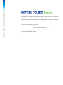
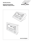
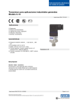
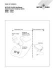
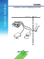
ICS466x
Explosion proof weighing terminal
Hazardous area
Safe area
RS422
CL20mA
RS232
Ex-i
ICS466x
Ex-i
Ex-i
ACM200
APS768x
Weighing platform
METTLER TOLEDO Service
2
Congratulations on choosing the quality and precision of METTLER TOLEDO. Proper use
according to these instructions and regular calibration and maintenance by our factorytrained service team ensure dependable and accurate operation to protect your investment.
Contact us about a service agreement tailored to your needs and budget.
We invite you to register your product at
www.mt.com/productregistration
so we can contact you about enhancements, updates and important notifications concern
ing your METTLER TOLEDO product.
METTLER TOLEDO
Guide for Installers ICS466x
Order number 22026623B
09/13
Contents
1
Safety instructions................................................................................................4
2
2.1
2.2
System overview..................................................................................................6
Typical configurations............................................................................................6
Description of components......................................................................................8
3Installation........................................................................................................10
3.1
Setting up system modules...................................................................................10
3.2
Connecting devices..............................................................................................11
3.3
Installing the equipotential bonding........................................................................12
3.4
Connecting power supply......................................................................................12
4
4.1
4.2
Optional work.....................................................................................................13
Customizing connection cables: Weighing platform / APS768x.................................13
Customizing connection cables: interface converter ACM200....................................14
5
5.1
Technical data....................................................................................................15
Dimensional drawing...........................................................................................15
6Disposal.............................................................................................................15
7
09/13
Control Drawing.................................................................................................16
Order number 22026623B
METTLER TOLEDO
Guide for Installers ICS466x
3
Safety instructions
1
4
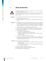
Safety instructions
The ICS466x weighing terminal is approved for operation in Zone 1 and 21 hazardous
areas as well as for Division 1 areas.
If the ICS466x weighing terminal is used in hazardous areas, special care must be
taken. The code of practice is oriented to the "Safe Distribution" concept drawn up by
METTLER TOLEDO.
METTLER TOLEDO
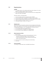
Competence
▲▲ The weighing system may only be installed, maintained and repaired by authorized
METTLER TOLEDO service personnel.
▲▲ The mains supply may only be installed by a specialist authorized by the owneroperator.
Ex approval
▲▲ No modifications may be made to the terminal and no repair work may be performed
on the modules. Any weighing platform or system modules that are used must comply
with the specifications contained in the installation instructions. Non-compliant
equipment jeopardizes the intrinsic safety of the system, cancels the "Ex" approval
and renders any warranty or product liability claims null and void.
▲▲ The safety of the weighing system is only guaranteed when the weighing system is
operated, installed and maintained in accordance with the respective instructions.
▲▲ Also comply with the following:
–– the instructions for the system modules,
–– the regulations and standards in the respective country,
–– the statutory requirement for electrical equipment installed in hazardous areas in
the respective country,
–– all instructions related to safety issued by the owner.
▲▲ The explosion-protected weighing system must be checked to ensure compliance with
the requirements for safety before being put into service for the first time, following any
service work and every 3 years, at least.
Operation
▲▲ Prevent the build-up of static electricity.
–– Always wear suitable working clothes when operating or performing service work
in a hazardous area.
–– Only use the weighing terminal when electrostatic processes leading to propagating
brush discharges are impossible.
▲▲ Do not use protective coverings for the devices.
▲▲ Protect the keyboard membrane against ultraviolet radiation.
▲▲ Avoid damage to the system components.
Guide for Installers ICS466x
Order number 22026623B
09/13
Installation
09/13
▲▲ Only install or perform maintenance work on the weighing system in the hazardous
areas if the following conditions are fulfilled:
–– the intrinsically safe characteristic values and zone approval of the individual
components are in accordance with one another,
–– the owner has issued a permit ("spark permit" or "fire permit"),
–– the area has been rendered safe and the owner's safety co-ordinator has confirmed
that there is no danger,
–– the necessary tools and any required protective clothing are provided (danger of
the build-up of static electricity).
▲▲ The certification papers (certificates, manufacturer’s declarations) must be present.
▲▲ Lay cabling securely so that it does not move and effectively protect it against damage.
▲▲ Only route cables into the housing of the system modules via the approved earthing
cable glands and ensure proper seating of the seals.
Order number 22026623B
METTLER TOLEDO
Guide for Installers ICS466x
5
System overview
2
System overview
2.1
Typical configurations
A weighing system with the ICS466x weighing terminal can be operated either with one of
the following power supply units:
APS768x-120 V
Power supply unit in a hazardous area, US version, 120 VAC,
50/60 Hz
APS768x-230 V
Power supply unit in a hazardous area, EU version, 230 VAC,
50 Hz
Either an analog or a digital weighing platform can be connected to the ICS466x weighing
terminal.
In addition, a communication box can be connected in the safe area, e.g. an ACM200.
The following components are necessary for the connection of peripheral devices:
ACM200
6
Interface converter for the safe area, e.g. for connection of a PC in the safe area
Wide range power supply unit 100 – 240 V AC, 50/60 Hz or 24 V DC
ICS466x digital scale interface
Active intrinsically safe scale interface for connection of digital weighing platforms, e.g.
K...x-T4
PDC-SG-Ex1
Active intrinsically safe A/D converter, installed in the ICS466x weighing terminal, to
connect analog weighing platforms in the hazardous area
ICS466x active CL interface
Optional active intrinsically safe data interface, to allow communication with the safe area,
e.g. via ACM200.
ICS466x passive CL interface
Optional passive intrinsically safe data interface, to connect a second intrinsically safe
digital scale interface. The second scale has to be powered externally by a second
APS768x.
ICS466x RS232-IS
Intrinsically safe communication interface, located on the ICS466x backplane, to connect
an intrinsically safe peripheral device, e.g. barcode reader, or via IS barrier to peripheral
equipment. Peripheral devices must be powered externally.
METTLER TOLEDO
Guide for Installers ICS466x
Order number 22026623B
09/13
2.1.1
Configuration with interface converter ACM200 in the safe area
Hazardous area
APS768x
Ex-i
max. 50 m
Safe area
ICS466x
PDCSG-Ex1
CL ACTIVE
Ex-i
max. 122 m
Ex-i
max.
300 m
ACM200
RS422/
CL20mA
RS232*
alternative
CL20mA*
alternative
RS422/485*
Analog weighing
platform
* only one hardware interface available,
CL20mA and RS422/485 only with module ACM200-CL/RS422
2.1.2
Configuration with PC in the safe area
Hazardous area
APS768x
Ex-i
max. 50 m
Safe area
ICS466x
PDCSG-Ex1
RS232-IS
Ex-i
max. 122 m
Ex-i
max. 10 m
PC
Zener
Barrier
Analog
weighing platform
09/13
Order number 22026623B
METTLER TOLEDO
Guide for Installers ICS466x
7
System overview
2.1.3
Configuration with two digital weighing platforms in the hazardous area
Hazardous area
APS768x
Ex-i
max. 50 m
ICS466x
DIGITAL
SCALE
Ex-i
max. 20 m
Safe area
CL ACTIVE
Ex-i
max.
300 m
CL PASSIVE
ACM200
RS422/
CL20mA
RS232*
alternative
CL20mA*
alternative
RS422/485*
APS768x
CL-CL
Digital weighing
platform,
e.g. K...x-T4
Digital weighing
platform,
e.g. KA15sx-T4
* only one hardware interface available,
CL20mA and RS422/485 only with module ACM200-CL/RS422
2.2
Description of components
2.2.1
Approvals
ICS466x
Power supply unit APS768x
Analog weighing platforms
Interface converter ACM200
8
METTLER TOLEDO
Guide for Installers ICS466x
Ignition protection type
EN/IECEx
CFMUS
II 2G Ex ib IIC T4 Gb, –10 °C ... +40 °C
II 2D Ex ib IIIC T60°C Db
IP65
IS Class I, II, III; Division 1;
Group A, B, C, D, E, F, G; T4; Ta = 40 °C
AEx ib IIC T4; IP65; Type 4
See APS768x Guide for Installers
See Operating Instructions / Installation Information of the weighing platforms
Ignition protection type
EN/IECEx
CFMUS
II (2)G [Ex ib Gb] IIC
II (2)D [Ex ib Db] IIIC
AIS Class I, II, III; Division 1;
Group A, B, C, D, E, F, G
Order number 22026623B
09/13
2.2.2
Connections
1
1
2
3
4
5
6
2
3
4
5
6
Power supply unit APS768x
Intrinsically safe RS232 interface
Communication interface
Second (digital) weighing platform
Weighing platform (analog or digital)
Equipotential bonding terminal (EB)
Note
On connections (1) to (4) blind plugs are mounted at the factory.
When connecting METTLER TOLEDO devices, M16x1.5 cable glands are provided with
the devices.
The cable gland on connection (5) is provided for connecting a third-party analog
weighing platform.
09/13
Order number 22026623B
METTLER TOLEDO
Guide for Installers ICS466x
9
Installation
3
Installation
EXPLOSION HAZARD
The explosion-protected weighing system may only be installed according to this Guide for
Installers and the Control Drawing 22026630 on Pages 16 to 19.
3.1
Setting up system modules
3.1.1
Setting up the ICS466x weighing terminal
➜➜ Select a suitable installation site.
Bench stand or floor stand mounting
➜➜ Place weighing terminal onto the bench or floor stand and mount with 4 screws.
Wall mounting
➜➜ The ICS466x weighing terminal can be mounted to a wall using the wall bracket
(accessory).
Setting up the power supply unit
➜➜ Set up the power supply unit in accordance with the corresponding instructions.
Setting up the weighing platform
➜➜ Set up the weighing platform in accordance with the corresponding Operating and
Installation Instructions.
Setting up the ACM200
➜➜ Set up the interface converter ACM200 in the safe area in accordance with the
corresponding instructions.
10
METTLER TOLEDO
Guide for Installers ICS466x
Order number 22026623B
09/13
3.2
Connecting devices
CAUTION
• The clamping section of the earthing cable gland must correspond to the outer
diameter of the weighing platform cable to be connected.
• Use the supplied flexible tubes to protect the individual wires of the weighing platform
cable on the inside of the ICS466x.
Connect the devices in the following order:
1. Connect the weighing platform to the weighing terminal ICS466x.
2. Connect the power supply unit APS768x to the weighing terminal ICS466x.
3. Connect the interface converter ACM200, if present, to the weighing terminal ICS466x.
4. Install the equipotential bonding, see section 3.3 on page 12.
5. Connect power supply, see section 3.4 on page 12.
09/13
3.2.1
Preparatory work
Connection of the devices is generally carried out with the accompanying standard cables.
Cables of other lengths can be used instead of the standard cables if they are customized
in accordance with Chapter 4.1 or 4.2. This applies for the following connections:
• from the weighing platform to the weighing terminal,
• from the power supply unit APS768x to the weighing terminal,
• from the interface converter ACM200 to the weighing terminal.
3.2.2
General connection procedure
1. Open the device.
2. Pull the customized cable through the earthing cable gland. To do this
–– dismantle the earthing cable gland or remove the blind plug,
–– ensure the exact course of the cable and properly positioned seals,
–– tighten the earthing cable gland.
3. Connect the cable in the device according to the control drawing.
4. Close device.
3.2.3
Interface installation
For installing an interface board refer to the ICS466x Service Manual.
Order number 22026623B
METTLER TOLEDO
Guide for Installers ICS466x
11
Installation
3.3
Installing the equipotential bonding
Equipotential bonding must be installed by an electrician authorized by the owner.
METTLER TOLEDO Service only has a monitoring and consulting function here.
➜➜ Connect equipotential bonding (EB) of all devices (power supply unit, weighing
terminal, interface converter and weighing platform) in accordance with the terminal
diagram and the country-specific regulations and standards. In the process it must
be ensured that
–– all device housings are connected to the same potential via the EB terminals,
–– no circulating current flows via the cable shielding for intrinsically safe circuits,
–– the neutral point for equipotential bonding is as close to the weighing system as
possible.
3.4
Connecting power supply
EXPLOSION HAZARD
The mains connection of the power supply unit must be made by a professional electrician
authorized by the owner and in accordance with the respective terminal diagram, the
accompanying installation instructions as well as the country-specific regulations.
12
METTLER TOLEDO
Guide for Installers ICS466x
Order number 22026623B
09/13
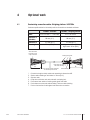
4
Optional work
4.1
Customizing connection cables: Weighing platform / APS768x
Customer-specific cables for intrinsically safe circuits must be customized as follows:
ICS466x – APS768x
ICS466x – Weighing platform
4 x 2 x 0.5 mm2 + 1 x 0.5 mm2
3 x 2 x 0.75 mm2
Dimension A
(ICS466x)
80 mm (3,1")
80 mm (3,1")
Dimension B
215 mm (8.5")
215 mm (8.5")
Max. length
50 m (165 ft)
analog scale: 122 m (400 ft)
digital scale: 20 m (66 ft)
Cable
Wire end ferrules
with plastic collar,
crimp connection
A
Earthing cable gland
Push sleeve over wires
and cable shielding
As per country-specific regulations
for intrinsically safe circuits
1.
2.
3.
4.
5.
6.
7.
09/13
Order number 22026623B
B
Cable shielding
Cut cable to length and strip cable ends according to dimensions A/B.
Shorten cable shielding on both sides to 10 mm (0.4").
Strip wire ends.
Crimp wire end ferrules onto wire ends with a crimping tool.
Push second rear section of earthing cable gland onto cable.
Push sleeve over wires and cable shielding. Fold over cable shielding.
Push on front section of cable gland and screw onto rear section.
METTLER TOLEDO
Guide for Installers ICS466x
13
Optional work
4.2
Customizing connection cables: interface converter ACM200
Customer-specific cables for intrinsically safe circuits must be customized as follows:
ICS466x – ACM200
2 x 2 x 0.5 mm2
Cable
Dimension A (ICS466x)
60 mm (2.4")
Dimension B
70 mm (2.8")
Max. length
300 m (1000 ft)
Wire end ferrules
with plastic collar,
crimp connection
A
Push sleeve over wires
and cable shielding
Earthing cable gland
B
Cable shielding
As per country-specific regulations
for intrinsically safe circuits
1.
2.
3.
4.
5.
6.
Cut cable to length and strip cable ends according to dimension A/B.
Shorten cable shielding on both sides to 10 mm (0.4").
Strip wire ends.
Crimp wire end ferrules onto wire ends with a crimping tool.
Push second rear section of earthing cable gland onto the cable.
Apply the cable shielding only to the ICS466x end. To do so, push the sleeve over the wires and the cable shielding and fold over the
cable shielding.
7. Push on front section of cable gland and screw onto rear section.
14
METTLER TOLEDO
Guide for Installers ICS466x
Order number 22026623B
09/13
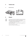
5
Technical data
5.1
Dimensional drawing
120
290
195
96
M5
95
190
6
Disposal
In conformance with the European Directive 2002/96 EC on Waste Electrical and Electronic
Equipment (WEEE), this device may not be disposed of with domestic waste. This also
applies to countries outside the EU, according to their specific requirements.
➜➜ Please dispose of this product in accordance with local regulations at the collecting
point specified for electrical and electronic equipment.
If you have any questions, please contact the responsible authority or the distributor from
which you purchased this device.
Should this device be passed on to other parties (for private or professional use), the
content of this regulation must also be related.
Thank you for your contribution to environmental protection.
09/13
Order number 22026623B
METTLER TOLEDO
Guide for Installers ICS466x
15
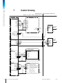
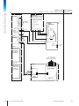
Control Drawing
7
Control Drawing
Hazardous Area
Class I, II, III; Div 1, Zone 1, Groups A-G, T4
Non-Hazardous (Safe) Area
APS768x 12)
ICS466x 12)
Backplane
J2-5
J2-4
J2-3
J2-2
J2-1
J1-4
J1-3
J1-2
J1-1
gray
brown
black
red
blue
white
yellow
green
pink
1) 6)
white
yellow
green
brown
U1
GND
U2
GND
U3
GND
U4
GND
U5
GND
U6
NC
pink
gray
black
red
blue
P: brown
N: blue
GND: gre/yel
Associated
intrinsically
safe
barrier 11)
5)
power
supply
To appropriate
equipment
RS232-IS
max. 50 m (165 ft)
TXD
RXD
GND
RTC
CTC
GND
J10-3
J10-2
J10-1
J 8-3
J 8-2
J 8-1
EB
4)
4)
Option 3
EB
ACM200
9)
CL ACTIVE
J 2-4
J 2-3
J 2-2
J 2-1
max. 10 m (33 ft)
blue
blue
yellow
yellow
red
orange
red
orange
COM1
COM2
COM3
COM4
3) 6)
see Control
Drawing
72203677
4)
EB
max. 300 m (1000 ft)
9)
K...x-T4 with TBrick-Ex
Option 2
Connection board
ME-42101840
DIGITAL SCALE
J 2-6
J 2-5
J 2-4
J 2-3
J 2-2
J 2-1
gray
pink
pink
yellow
gray
yellow
brown
green
white
5
9
10
8
U1
GND
U2
GND
7 TX+
6 RX+
brown
white
green
2) 6)
4)
EB
max. 20 m (66 ft)
Option 18)
PDC-SG-Ex1
J201-6
J201-5
J201-4
J201-3
J201-2
J201-1
EXC–
SEN–
SIG–
SIG+
SEN+
EXC+
2) 6)
Analog Scale
EXC+ CENELEC/FM approved
SEN+ equipment for category 2 / DIV1
SIG+ in accordance with the following
SIG– intrinsically safe parameters:
SEN–
Ui / Umax ≥ Uo / Uoc
BXC–
Ii / Imax > Io / Isc
Ci + CCable ≤ Co / Ca
Li + LCable ≤ Lo / La
4)
EB
max. 122 m (400 ft)
EB
16
METTLER TOLEDO
Guide for Installers ICS466x
4)
Order number 22026623B
09/13
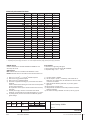
Intrinsically safe connection values
APS768x
Uo [V]
Io [mA]
P0 [W]
Co [mF]
Lo [mH]
U1
8.7
133
1.15
1
0.3
U2
12.6
42
0.53
0.4
1
U3
7.15
107
0.77
1
0.3
U4
10.5
74
0.78
0.6
0.3
U5
5.4
240
1.30
1
0.3
U6
12.6
92
1.16
0.5
0.3
Uo [V]
Io [mA]
P0 [W]
Co [mF]
Lo [mH]
5.36
107
0.574
0.2
0.3
Uo [V]
Io [mA]
P0 [W]
Co [mF]
Lo [mH]
PDC-SG-Ex1
J201
DIGITAL SCALE
J2.6 / J3.3
12.6
42
0.53
*
J2.5 / J3.6
8.7
133
1.16
**
J2.2 / J3.2
5.36
30
0.040
0.1
J2.1 / J3.1
5.36
30
0.040
0.1
0.1
Uo [V]
Io [mA]
P0 [mW]
Co [mF]
Lo [mH]
0.2
APS768x-CL/CL
0.1
Scale interface S1–S4
7.15
24
43
0.2
Communication interface C1–C4
7.15
107
270
0.3
0.6
Uo [V]
Io [mA]
P0 [mW]
Co [mF]
Lo [mH]
J8.3
±5.36
±18.1
24.2
0.1
0.1
J10.3
±5.36
±18.1
24.2
0.1
0.1
Uo [V]
Io [mA]
P0 [mW]
Co [mF]
Lo [mH]
±5.36
74
397
0.6
0.4
Ui [V]
Ii [mA]
Pi [mW]
Ci [mF]
Li [mH]
10
300
500
0.11
negligible
RS232-IS
CL ACTIVE
J2
CL PASSIVE
J4
* Depending on the power supply connected to J1-2 on the backplane and cable (length) between power supply and terminal
** Depending on the power supply connected to J1-4 on the backplane and cable (length) between power supply and terminal
CENELEC approval
Cables in accordance with standards EN50039 and EN60079-14 for
intrinsically safe circuits.
CFMUS
approval
USA: Installation shall be in accordance with ANSI/ISA RP 12.6.01.
Canada: Installation shall be in accordance with the Electrical Code C2.R1.
Cable 4 x 2 x 0.5 mm2 + 1 x 0.5 mm2 shielded and paired
Cable 6 x 0.5 mm2 shielded and paired
Cable 4 x 0.5 mm2 shielded and paired
Connection of equipotential bonding (EB) in accordance with national
regulations.
It must be ensured that the housing of all units are at the same potential
by means of EB connections.
No compensation current may flow across the shield of the intrinsically
safe cables.
5) APS768x power supply connection in accordance with national
regulations, see model plate for line voltage and frequency. Um ≤ 250 V.
6) Lay cabling securely so that it does not move and effectively protect it
against damage.
1)
2)
3)
4)
A
Edition
/
Revision
25.09.2013
Date
Varga
Name
Date
06.05.2013 Varga
Check
06.05.2013 Lebherz
Replaces:
/
METTLER TOLEDO
09/13
Name
Prep.
For all approvals
• Cable lead-in via grounding cable gland
• Cable according to Guide for Installers ME‑22026623
• Temperature range: –10 °C ... +40 °C
7) Via internal cables in APS768x.
8) The use of Option 1 (Scale 1) is mandatory, either PDC-SG-EX1 or
Digital scale. For a second scale, the combinations as shown on Sheet
1 to Sheet 2 are available.
9) Cable seal between differently rated areas, as per country specific
regulations.
10)Internal cable for a compact scale.
11)FM approved for US installations and suitably certified for Canada for
Canadian installations.
12)Also certified according to NEC505: AEx ib IIC T4; AEx em [ib] IIC T4
Scale
Designation
Control Drawing ICS466x
Sheet 1/3
Mettler-Toledo (Albstadt) GmbH
D-72458 Albstadt
Order number 22026623B
Code
22026630
METTLER TOLEDO
Guide for Installers ICS466x
17
Control Drawing
Hazardous Area
Class I, II, III; Div 1, Zone 1, Groups A-G, T4
ICS466x 12)
ICS466x
Backplane
Backplane
RS232-IS
J2-5
J2-4
J2-3
J2-2
J2-1
J1-4
J1-3
J1-2
J1-1
TXD
RXD
GND
RTC
CTC
GND
J10-3
J10-2
J10-1
J 8-3
J 8-2
J 8-1
Option 3
CL ACTIVE
EB
4)
white
yellow
green
brown
pink
1)
gray
to APS768x,
see sheet 1/3
Option 3
CL PASSIVE
blue
yellow
max. 300 m
(1000 ft)
red
orange
J 4-4
J 4-3
J 4-2
J 4-1
brown
black
red
blue
white
yellow
green
pink
J 2-4
J 2-3
J 2-2
J 2-1
J 1-4
J 1-3
J 1-2
J 1-1
gray
black
red
blue
1) 6)
U1
GND
U2
GND
U3
GND
U4
GND
U5
GND
U6
NC
max. 50 m (165 ft)
P: brown
N: blue
GND: gre/yel
3) 6)
J 2-4
J 2-3
J 2-2
J 2-1
blue
yellow
APS768x12) P: brown
Option 2
CL PASSIVE
2nd Digital Scale
interface, if Option 1
is a Digital Scale
3) 6)
blue
yellow
red
orange
red
orange
C 1
C 2
C 3
C 4
K...x-T4 with
TBrick-Ex
pink
yellow
gray
brown
white
green
7)
red
black
P 1
P 2
S
S
S
S
power
supply
pink
yellow
gray
brown
red
black
U1
GND
U2
GND
U3
GND
U4
GND
U5
GND
U6
NC
APS768x-CL/CL
blue
yellow
5)
5)
power
supply
N: blue
GND: gre/yel
red
orange
APS768x
Module
J 4-4
J 4-3
J 4-2
J 4-1
4)
APS768x 12)
EB
J 2-5
Non-Hazardous
(Safe) Area
Connection board
ME-42101840
5
9
10
8
7
6
U1
GND
U2
GND
TX+
RX-
white
1
2
3
4
green
2) 6)
max. 100 m (330 ft)
max. 20 m (66 ft)
4)
EB
Option 18)
DIGITAL SCALE
either
J 2-6
J 2-5
J 2-4
J 2-3
J 2-2
J 2-1
gray
2) 6)
pink
yellow
brown
green
white
pink
yellow
gray
brown
white
green
max. 20 m (66 ft)
or
J3
10)
4)
EB
K...x-T4 with TBrick-Ex
Connection board
ME-42101840
5
9
10
8
7
6
U1
GND
U2
GND
TX+
RX+
alternatively
K...x-T4 with
TBrick-Ex
EB
4)
4)
EB
4)
EB
18
METTLER TOLEDO
Guide for Installers ICS466x
Order number 22026623B
09/13
Intrinsically safe connection values
APS768x
Uo [V]
Io [mA]
P0 [W]
Co [mF]
Lo [mH]
U1
8.7
133
1.15
1
0.3
U2
12.6
42
0.53
0.4
1
U3
7.15
107
0.77
1
0.3
U4
10.5
74
0.78
0.6
0.3
U5
5.4
240
1.30
1
0.3
U6
PDC-SG-Ex1
12.6
92
1.16
0.5
0.3
Uo [V]
Io [mA]
P0 [W]
Co [mF]
Lo [mH]
J201
DIGITAL SCALE
5.36
107
0.574
0.2
0.3
Uo [V]
Io [mA]
P0 [W]
Co [mF]
Lo [mH]
J2.6 / J3.3
12.6
42
0.53
*
J2.5 / J3.6
8.7
133
1.16
**
J2.2 / J3.2
5.36
30
0.040
0.1
J2.1 / J3.1
5.36
30
0.040
0.1
0.1
Uo [V]
Io [mA]
P0 [mW]
Co [mF]
Lo [mH]
0.2
APS768x-CL/CL
0.1
Scale interface S1–S4
7.15
24
43
0.2
Communication interface C1–C4
7.15
107
270
0.3
0.6
Uo [V]
Io [mA]
P0 [mW]
Co [mF]
Lo [mH]
±5.36
±18.1
24.2
0.1
0.1
RS232-IS
J8.3
±5.36
±18.1
24.2
0.1
0.1
Uo [V]
Io [mA]
P0 [mW]
Co [mF]
Lo [mH]
J10.3
CL ACTIVE
J2
CL PASSIVE
J4
±5.36
74
397
0.6
0.4
Ui [V]
Ii [mA]
Pi [mW]
Ci [mF]
Li [mH]
10
300
500
0.11
negligible
* Depending on the power supply connected to J1-2 on the backplane and cable (length) between power supply and terminal
** Depending on the power supply connected to J1-4 on the backplane and cable (length) between power supply and terminal
CENELEC approval
Cables in accordance with standards EN50039 and EN60079-14 for
intrinsically safe circuits.
CFMUS
approval
USA: Installation shall be in accordance with ANSI/ISA RP 12.6.01.
Canada: Installation shall be in accordance with the Electrical Code C2.R1.
Cable 4 x 2 x 0.5 mm2 + 1 x 0.5 mm2 shielded and paired
Cable 6 x 0.5 mm2 shielded and paired
Cable 4 x 0.5 mm2 shielded and paired
Connection of equipotential bonding (EB) in accordance with national
regulations.
It must be ensured that the housing of all units are at the same potential
by means of EB connections.
No compensation current may flow across the shield of the intrinsically
safe cables.
5) APS768x power supply connection in accordance with national
regulations, see model plate for line voltage and frequency. Um ≤ 250 V.
6) Lay cabling securely so that it does not move and effectively protect it
against damage.
1)
2)
3)
4)
A
Edition
/
25.09.2013
Revision
Date
Varga
Name
Date
06.05.2013 Varga
Check
06.05.2013 Lebherz
Replaces:
/
METTLER TOLEDO
09/13
Name
Prep.
For all approvals
• Cable lead-in via grounding cable gland
• Cable according to Guide for Installers ME‑22026623
• Temperature range: –10 °C ... +40 °C
7) Via internal cables in APS768x.
8) The use of Option 1 (Scale 1) is mandatory, either PDC-SG-EX1 or
Digital scale. For a second scale, the combinations as shown on Sheet
1 to Sheet 2 are available.
9) Cable seal between differently rated areas, as per country specific
regulations.
10)Internal cable for a compact scale.
11)FM approved for US installations and suitably certified for Canada for
Canadian installations.
12)Also certified according to NEC505: AEx ib IIC T4; AEx em [ib] IIC T4
Scale
Designation
Control Drawing ICS466x
Sheet 2/3
Mettler-Toledo (Albstadt) GmbH
D-72458 Albstadt
Order number 22026623B
Code
22026630
METTLER TOLEDO
Guide for Installers ICS466x
19
ICS466x12)
Backplane
J2-5
J2-4
J2-3
J2-2
J2-1
J1-4
J1-3
J1-2
J1-1
RS232-IS
Control Drawing
Hazardous Area
Class I, II, III; Div 1, Zone 1, Groups A-G, T4
TXD
RXD
GND
RTC
CTC
GND
J10-3
J10-2
J10-1
J 8-3
J 8-2
J 8-1
1)
to APS768x,
see sheet 1/3
Barcode Reader
CENELEC/FM approved barcode
reader for category 2 / Div1 in
accordance with the following
intrinsically safe parameters:
Ui / Umax ≥ Uo / Uoc
Ii / Imax ≥ Io / Isc
Ci + CCable ≤ Co / Ca
Li + LCable ≤ Lo / La
U1
GND
U2
GND red
U3
GND orange
U4
GND
U5
GND
U6
blue
NC
GND +5V
RxD TxD
3) 6)
red
orange
Option 3
CL ACTIVE
J 2-4
J 2-3
J 2-2
J 2-1
4)
EB
APS768x 12)
(Option Barcode)
blue
yellow
Non-Hazardous
(Safe) Area
blue
yellow
yellow
red
orange
NC
max. 10 m (33 ft)
P: brown
N: blue
GND: gre/yel
Option 2
5)
power
supply
see sheet 1/3
(Digital Scale)
or sheet 2/3
(CL PASSIVE)
to Ex-i power Supply
see Control Drawing 72203677
(IND226x Remote Connection)
Option 18)
IND226x
see sheet 1/3
(PDC-SG-Ex1)
or sheet 2/3
(Digital Scale)
max. 300 m
(1000 ft)
EB
METTLER TOLEDO
EB
1 2 3 4 5 6 7 8 9
IND226x Mainboard
COM4
blue
yellow
red
orange
20
4)
P
4)
Guide for Installers ICS466x
1
2
3
4
J2
J4
J
1
2
Interface
Remote
B
1 2 3 4 5 6
Order number 22026623B
09/13
Intrinsically safe connection values
APS768x
Uo [V]
Io [mA]
P0 [W]
Co [mF]
Lo [mH]
U1
8.7
133
1.15
1
0.3
U2
12.6
42
0.53
0.4
1
U3
7.15
107
0.77
1
0.3
U4
10.5
74
0.78
0.6
0.3
U5
5.4
240
1.30
1
0.3
U6
PDC-SG-Ex1
12.6
92
1.16
0.5
0.3
Uo [V]
Io [mA]
P0 [W]
Co [mF]
Lo [mH]
J201
DIGITAL SCALE
5.36
107
0.574
0.2
0.3
Uo [V]
Io [mA]
P0 [W]
Co [mF]
Lo [mH]
J2.6 / J3.3
12.6
42
0.53
*
J2.5 / J3.6
8.7
133
1.16
**
J2.2 / J3.2
5.36
30
0.040
0.1
J2.1 / J3.1
5.36
30
0.040
0.1
0.1
Uo [V]
Io [mA]
P0 [mW]
Co [mF]
Lo [mH]
0.2
APS768x-CL/CL
0.1
Scale interface S1–S4
7.15
24
43
0.2
Communication interface C1–C4
7.15
107
270
0.3
0.6
Uo [V]
Io [mA]
P0 [mW]
Co [mF]
Lo [mH]
±5.36
±18.1
24.2
0.1
0.1
RS232-IS
J8.3
±5.36
±18.1
24.2
0.1
0.1
Uo [V]
Io [mA]
P0 [mW]
Co [mF]
Lo [mH]
J10.3
CL ACTIVE
J2
CL PASSIVE
J4
±5.36
74
397
0.6
0.4
Ui [V]
Ii [mA]
Pi [mW]
Ci [mF]
Li [mH]
10
300
500
0.11
negligible
* Depending on the power supply connected to J1-2 on the backplane and cable (length) between power supply and terminal
** Depending on the power supply connected to J1-4 on the backplane and cable (length) between power supply and terminal
CENELEC approval
Cables in accordance with standards EN50039 and EN60079-14 for
intrinsically safe circuits.
CFMUS
approval
USA: Installation shall be in accordance with ANSI/ISA RP 12.6.01.
Canada: Installation shall be in accordance with the Electrical Code C2.R1.
Cable 4 x 2 x 0.5 mm2 + 1 x 0.5 mm2 shielded and paired
Cable 6 x 0.5 mm2 shielded and paired
Cable 4 x 0.5 mm2 shielded and paired
Connection of equipotential bonding (EB) in accordance with national
regulations.
It must be ensured that the housing of all units are at the same potential
by means of EB connections.
No compensation current may flow across the shield of the intrinsically
safe cables.
5) APS768x power supply connection in accordance with national
regulations, see model plate for line voltage and frequency. Um ≤ 250 V.
6) Lay cabling securely so that it does not move and effectively protect it
against damage.
1)
2)
3)
4)
A
Edition
/
25.09.2013
Revision
Date
Varga
Name
Date
06.05.2013 Varga
Check
06.05.2013 Lebherz
Replaces:
/
METTLER TOLEDO
09/13
Name
Prep.
For all approvals
• Cable lead-in via grounding cable gland
• Cable according to Guide for Installers ME‑22026623
• Temperature range: –10 °C ... +40 °C
7) Via internal cables in APS768x.
8) The use of Option 1 (Scale 1) is mandatory, either PDC-SG-EX1 or
Digital scale. For a second scale, the combinations as shown on Sheet
1 to Sheet 2 are available.
9) Cable seal between differently rated areas, as per country specific
regulations.
10)Internal cable for a compact scale.
11)FM approved for US installations and suitably certified for Canada for
Canadian installations.
12)Also certified according to NEC505: AEx ib IIC T4; AEx em [ib] IIC T4
Scale
Designation
Control Drawing ICS466x
Sheet 3/3
Mettler-Toledo (Albstadt) GmbH
D-72458 Albstadt
Order number 22026623B
Code
22026630
METTLER TOLEDO
Guide for Installers ICS466x
21
To protect your METTLER TOLEDO
product’s future:
METTLER TOLEDO Service assures the
quality, measuring accuracy and preservation of value of all METTLER TOLEDO
products for years to come.
Please send for full details about our
attractive terms of service.
Thank you.
www.mt.com/service
For more information
Mettler-Toledo (Albstadt) GmbH
D-72458 Albstadt
Tel.
+ 49 7431-14 0
Fax
+ 49 7431-14 232
Subject to technical changes
© 09/2013 Mettler-Toledo (Albstadt) GmbH
Printed in Germany
Order number 22026623B
*22026623B*
* 2 2 0 2 6 6 2 3 B *