1
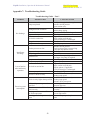
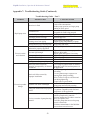
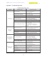
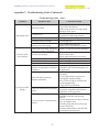
Premier Supplier of Pumps & Parts
Troubleshooting for:
115 Hilton Street West • Easton, PA 18042 USA • (800)854-0539 • fax: (800)926-9508 • http://www.ProcessFlo.com
Liquiflo Installation, Operation & Maintenance Manual
SEALED Gear Pumps
Models H1-H9, 31-39 & 311
Appendix 7: Troubleshooting Guide
Troubleshooting Guide – Part 1
Problem
Possible Cause
Corrective Action
Verify suction pipe is submerged.
Increase suction pressure.
Open suction valve.
Reverse motor leads or reverse suction
Wrong direction of rotation
and discharge piping.
Valves closed
Open all suction and discharge valves.
Bypass valve open
Close bypass valve.
Tighten connections.
Air leak in suction line
Apply sealant to all threads.
Verify suction pipe is submerged.
Clogged strainer
Clean strainer.
Pump worn or damaged
Rebuild pump.
Increase suction pressure.
Suction pressure too low
Verify suction piping is not too long.
Fully open any suction valves.
Bypass valve open
Close bypass valve.
Partly clogged strainer
Clean strainer.
Increase driver speed, if possible.
Speed too low
Use larger size pump, if required.
Pump worn or damaged
Rebuild pump.
Pump not properly primed
Reprime pump.
Tighten connections.
Apply sealant to all threads.
Air leaks in suction line
Inspect gaskets, if applicable.
Verify suction pipe is submerged.
Air or vapor pockets in suction line Rearrange piping as necessary.
Heat fluid to reduce viscosity.
Increase in fluid viscosity
Reduce pump speed.
Heat fluid to reduce viscosity.
Fluid viscosity higher than specified Reduce pump speed.
Increase driver horsepower.
Differential pressure greater than
Increase pipe diameter.
specified
Decrease pipe run.
Gear clearances insufficient for
Purchase gears trimmed for the correct
fluid viscosity
viscosity.
Plastic gear clearance insufficient
Purchase plastic gear trimmed for the
for fluid temperature
correct temperature.
Rotating parts binding or severely
Disassemble pump and replace worn
worn
parts.
Pump not primed
No discharge
Insufficient
discharge
Loss of suction
after satisfactory
operation
Excessive power
consumption
58
Liquiflo Installation, Operation & Maintenance Manual
SEALED Gear Pumps
Models H1-H9, 31-39 & 311
Appendix 7: Troubleshooting Guide (Continued)
Troubleshooting Guide – Part 2
Problem
Possible Cause
Corrective Action
Abrasives in fluid
Corrosion wear
Rapid pump wear
Extended dry running
Discharge pressure too high
Housing stress from piping
Misalignment (long-coupled pump)
Suction and/or discharge piping not
anchored or properly supported
Excessive noise
and vibration
Base not rigid enough
Worn pump bearings
Worn motor bearings
Pump cavitation
Misalignment (long-coupled pump)
Static seal failure caused by
chemical incompatibility or thermal
breakdown
Static seal failure caused by
improper installation
Excessive product
leakage
Dynamic seal worn or damaged
Pump port connections not properly
sealed
Crevice corrosion of pump housing
material
59
Install suction strainer.
Limit solids concentration.
Reduce pump speed or use larger pump
running at lower speed.
Use materials of construction that are
acceptable for fluid being pumped.
Install power sensor to stop pump.
Increase pipe diameter.
Decrease pipe run.
Align piping with pump ports.
Support piping independently of pump.
Align pump and motor.
Anchor per Hydraulic Institute Standards.
Tighten hold-down bolts on pump and
motor or adjust stilts.
Inspect grout and regrout if necessary.
Replace bearings.
Replace bearings or motor.
Increase NPSH available.
Align pump and motor.
Use O-rings or gaskets made of material
compatible with fluid and temperature of
the application.
Install O-rings or gaskets without twisting
or bending.
Use star-pattern torque sequence on
housing bolts during assembly.
Allow Teflon O-rings to cold flow and
seat during tightening.
Torque bolts to specification.
Disassemble and replace seal.
Prime pump and avoid dry running.
Use Teflon tape or other suitable sealant.
Use gaskets compatible with fluid and
temperature of the application.
Only pump chemicals that are compatible
with the pump housing material.
Decrease temperature to reduce corrosion
rate to acceptable value.
Flush idle pumps that are used to pump
corrosive chemicals.
Eliminate contaminants in the fluid that
can accelerate corrosion wear.
Liquiflo Installation, Operation & Maintenance Manual
MAG-DRIVE Gear Pumps
Models H1-H9, 31-39 & 311 - MC
Appendix 7: Troubleshooting Guide
Troubleshooting Guide – Part 1
Problem
Possible Cause
Corrective Action
Verify suction pipe is submerged.
Increase suction pressure.
Open suction valve.
Reverse motor leads or reverse suction
Wrong direction of rotation
and discharge piping.
Valves closed
Open all suction and discharge valves.
Bypass valve open
Close bypass valve.
Tighten connections.
Air leak in suction line
Apply sealant to all threads.
Verify suction pipe is submerged.
Clogged strainer
Clean strainer.
Pump worn or damaged
Rebuild pump.
Stop driver and check temperature and
viscosity of fluid.
Magnetic coupling has decoupled
Verify position of outer magnet.
Stronger magnetic coupling may be
needed.
Increase suction pressure.
Suction pressure too low
Verify suction piping is not too long.
Fully open any suction valves.
Bypass valve open
Close bypass valve.
Partly clogged strainer
Clean strainer.
Increase driver speed, if possible.
Speed too low
Use larger size pump, if required.
Pump worn or damaged
Rebuild pump.
Reprime pump.
Pump not properly primed
Tighten connections.
Apply sealant to all threads.
Air leaks in suction line
Inspect gaskets, if applicable.
Verify suction pipe is submerged.
Air or vapor pockets in suction line Rearrange piping as necessary.
Heat fluid to reduce viscosity.
Increase in fluid viscosity
Reduce pump speed.
Heat fluid to reduce viscosity.
Fluid viscosity higher than specified Reduce pump speed.
Increase driver horsepower.
Differential pressure greater than
Increase pipe diameter.
specified
Decrease pipe run.
Gear clearances insufficient for
Purchase gears trimmed for the correct
fluid viscosity
viscosity.
Plastic gear clearance insufficient
Purchase plastic gear trimmed for the
for fluid temperature
correct temperature.
Rotating parts binding or severely
Disassemble pump and replace worn
worn
parts.
Pump not primed
No discharge
Insufficient
discharge
Loss of suction
after satisfactory
operation
Excessive power
consumption
46
Liquiflo Installation, Operation & Maintenance Manual
MAG-DRIVE Gear Pumps
Models H1-H9, 31-39 & 311 - MC
Appendix 7: Troubleshooting Guide (Continued)
Troubleshooting Guide – Part 2
Problem
Possible Cause
Corrective Action
Abrasives in fluid
Rapid pump wear
Corrosion wear
Extended dry running
Discharge pressure too high
Housing stress from piping
Suction and/or discharge piping not
anchored or properly supported
Excessive noise
and vibration
Base not rigid enough
Worn pump bearings
Worn motor bearings
Pump cavitation
Static seal failure caused by
chemical incompatibility or thermal
breakdown
Static seal failure caused by
improper installation
Excessive product
leakage
Pump port connections not properly
sealed
Crevice corrosion of pump housing
material
47
Install suction strainer.
Limit solids concentration.
Reduce pump speed or use larger pump
running at lower speed.
Use materials of construction that are
acceptable for fluid being pumped.
Install power sensor to stop pump.
Increase pipe diameter.
Decrease pipe run.
Align piping with pump ports.
Support piping independently of pump.
Anchor per Hydraulic Institute Standards.
Tighten hold-down bolts on pump and
motor or adjust stilts.
Inspect grout and regrout if necessary.
Replace bearings.
Replace bearings or motor.
Increase NPSH available.
Use O-rings or gaskets made of material
compatible with fluid and temperature of
the application.
Install O-rings or gaskets without twisting
or bending.
Use star-pattern torque sequence on
housing bolts during assembly.
Allow Teflon O-rings to cold flow and
seat during tightening.
Torque bolts to specification.
Use Teflon tape or other suitable sealant.
Use gaskets compatible with fluid and
temperature of the application.
Only pump chemical fluids that are
compatible with the pump housing
material.
Decrease temperature to reduce corrosion
rate to acceptable value.
Flush idle pumps that are used to pump
corrosive chemicals.
Eliminate contaminants in the fluid that
can accelerate corrosion wear.
Premier Supplier of Pumps & Parts
Troubleshooting for:
115 Hilton Street West • Easton, PA 18042 USA • (800)854-0539 • fax: (800)926-9508 • http://www.ProcessFlo.com
CHAPTER 7: TROUBLESHOOTING
Symptom or Problem: Pump is excessively noisy.
Possible Cause(s):
x Air in the inlet fluid stream.
x Relief valve is opening.
x Pump has decoupled.
x Pump components are damaged or worn.
x Pump is cavitating.
x Discharge line is too restrictive.
x Cooling path is plugged.
x Ball bearings are worn or damaged.
Symptom or Problem: Pump does not prime.
Possible Cause(s):
x Discharge line is too restrictive.
x Suction lift is too great.
x Pump is not wetted.
x Air leak in the suction line.
x Pump is running in the wrong direction.
x Head is positioned incorrectly.
x Cooling path plugs are not installled.
x Pump is locked up with hardened fluid or foreign items.
x Pump components are damaged or worn.
x Pump has decoupled.
x Inner magnets have weakened.
x Cooling path is plugged.
x Relief valve is stuck open.
Symptom or Problem: Flowrate is too low.
Possible Cause(s):
x Head is positioned incorrectly.
x Cooling path plugs are not installled.
x Discharge line is too restrictive.
x Viscosity is lower than expected.
x Air in the inlet fluid stream.
x Pump is cavitating.
x Relief valve is opening.
x Pump components are damaged or worn.
x Bypass or auxiliary line in the discharge piping is open.
x Cooling path is plugged.
x Relief valve is stuck open.
Page 47 of 49
rev 7-14-2008
Symptom or Problem: Pump does not develop enough pressure.
Possible Cause(s):
x Air in the inlet fluid stream.
x Viscosity is lower than expected.
x Pump is cavitating.
x Relief valve is opening.
x Pump components are damaged or worn.
x Bypass or auxiliary line in the discharge piping is open.
x Head is positioned incorrectly.
x Cooling path plugs are not installled.
x Cooling path is plugged.
x Relief valve is stuck open.
Symptom or Problem: Relief valve does not open.
Possible Cause(s):
x Pump is running in the wrong direction.
x Relief valve is stuck closed.
Symptom or Problem: Leakage from head/casing area.
Possible Cause(s):
x O-ring material is not compatable with the pumped fluid.
x Sealing surfaces for the o-rings are damaged.
x Bolt(s) are loose or missing.
x O-ring is damaged or missing.
Symptom or Problem: Leakage from casing/magnet housing area.
Possible Cause(s):
x O-ring material is not compatable with the pumped fluid.
x Sealing surfaces for the o-rings are damaged.
x Casing or magnet housing mounting flanges are cracked.
x Bolt(s) are loose or missing.
x O-ring is damaged or missing.
Symptom or Problem: Leakage from head/valve body area.
Possible Cause(s):
x O-ring material is not compatable with the pumped fluid.
x Sealing surfaces for the o-rings are damaged.
x Bolt(s) are loose or missing.
x O-ring is damaged or missing.
Symptom or Problem: Leakage from drive shaft area.
Possible Cause(s):
x Canister is damaged and leaking.
Symptom or Problem: Excessive vibration.
Possible Cause(s):
x Air in the inlet fluid stream.
x Relief valve is opening.
x Pump has decoupled.
x Pump components are damaged or worn.
x Pump is cavitating.
x Ball bearings are worn or damaged.
x Inner magnets have weakened.
x Cooling path is plugged.
Page 48 of 49
rev 7-14-2008
Symptom or Problem: Pump draws too much power.
Possible Cause(s):
x Pump components are damaged or worn.
x Relief valve is stuck closed.
x Ball bearings are worn or damaged.
x Viscosity is higher than expected.
CHAPTER 8: HOW TO RETURN PUMP TO FACTORY
If a pump must be returned to the PeopleFlo factory, a Return Goods Authorization (RGA) must
be obtained from PeopleFlo or its authorized selling partners. No RGA can be issued without a
review of the appropriate Material Safety Data Sheets (MSDS). Pumps must be cleaned of all
fluids and the ports plugged to prevent foreign material from getting into the pump.
CHAPTER 9: WARRANTY
PeopleFlo Manufacturing, Inc. (“PMI”) warrants that on the day of delivery, all products
manufactured by it shall be free from defects in materials and workmanship. For a period twenty
four (24) months from the date of shipment from PMI, PMI will, at its sole and exclusive
discretion, either replace or repair any products found by PMI to be defective in workmanship or
material, at no charge to the Purchaser.
The warranty does not apply to:
x
x
x
x
any products which have been modified or altered by persons other than PMI; or
any products subjected to any misuse, neglect, misapplication, improper installation or
accidental damage; or
any goods manufactured by a third party; or
any products damaged by the effects of abrasion, erosion or corrosion.
No returns will be accepted by PMI unless accompanied by PMI’s written authorization and PMI
will assume no field expense for service or parts unless authorized in writing by PMI in advance.
All warranty replacement or repairs must be performed by PMI or a PMI Authorized Service
Organization.
PMI assumes no liability for consequential damages of any kind and the purchaser, by
acceptance of delivery, assumes all liability for the consequences of the use or misuse of PMI
products by the purchaser, the purchaser’s employees or others.
This warranty is exclusively for the benefit of the first purchaser of the product, other than a
purchaser for resale, and cannot be transferred or assigned.
THERE SHALL BE NO OTHER WARRANTY, EXPRESS OR IMPLIED, INCLUDING ANY
IMPLIED WARRANTY OF MERCHANTABILITY OR FITNESS FOR A PARTICULAR PURPOSE
OR ANY OTHER OBLIGATION ON THE PART OF PMI WITH RESPECT TO PRODUCTS
EXCEPT THE WARRANTY OR WARRANTIES CONTAINED HEREIN.
Page 49 of 49
rev 7-14-2008
Premier Supplier of Pumps & Parts
Troubleshooting for:
115 Hilton Street West • Easton, PA 18042 USA • (800)854-0539 • fax: (800)926-9508 • http://www.ProcessFlo.com
Service Manual 73
Troubleshooting
1. Problem: No fluid is delivered.
a. Power is not on.
b. Net positive suction head available (NPSHa) is lower than required for the vapor pressure
of the liquid pumped. You should calculate NPSHa and redesign piping, if necessary.
c.
Leaks in suction line or port passages. These can be detected by submerging pressure
line from discharge side of pump into a pail of liquid where the air will be seen in the form
of bubbles.
d. Direction of shaft rotation is incorrect.
e. Relief valve setting is too low. Liquid is discharging through the bypass port.
2. Problem: Capacity is too low.
a. Air leaks in suction line.
b. Suction losses are too high. The suction lift is too great or the suction line is too small or
too long. This can be detected by installing a vacuum gauge directly at the pump suction.
The maximum vacuum at the pump suction should never exceed 15” of mercury.
Vaporization caused by higher vacuums will generally result in capacity drop off.
Redesign suction conditions.
c.
Pump speed is too slow.
d. Strainer too small or obstructed.
e. Suction pipe or port not immersed deep enough in liquid.
f.
Piping improperly installed permitting air pocket to form in the pump.
g. Increased clearances or wear in the pump will sometimes cause the pump to deliver an
insufficient supply of liquid. This may be corrected by reducing the thickness of the cover
gaskets. A folded gasket or a slight amount of dirt can exaggerate the problem and
cause leakage. Refer to Assembly Procedure section for minimum end clearances.
3. Problem: Pump works spasmodically.
a. Leaky suction lines.
b. Suction conditions vary.
c.
Air or vapor in liquid.
4. Problem: Excessive power draw.
a. Pressure too high.
b. Liquid more viscous than originally expected.
v 1.8
Page 38 of 40
02/05/09
Service Manual 73
c.
Suction or discharge lines obstructed.
d. Insufficient horsepower.
e. Mechanical defects:
x Drive shaft and pump are misaligned.
x Pump is binding due to insufficient end clearance.
x Pump shaft is bent.
x Misalignment within pump due to bad piping or poor installation, causing strain or
distortion.
5. Problem: Pump is noisy.
a. Pump is cavitating due to inadequate suction conditions.
b. Misalignment of coupling.
c.
Coupling set too close to pump.
d. Vibration of pump due to worn or bent shaft.
e. Air leaks on suction side of pump or air entrainment in fluid.
6. Problem: Pump leaks.
a. Bolts need tightening, allowing gaskets or O-rings to leak.
b. Gaskets or O-rings are damaged.
Note: Packings are designed to leak. Leakage should be at a rate that will prevent excessive
heating on the bracket at the packing area.
v 1.8
Page 39 of 40
02/05/09