1
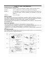
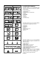
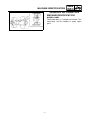
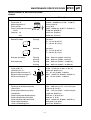
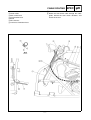
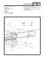
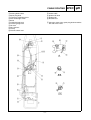
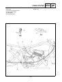
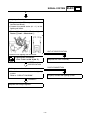
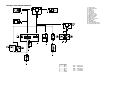
2002 YFS200(P) 2XJ-AE2 SUPPLEMENTARY SERVICE MANUAL FOREWORD This Supplementary Service Manual has been prepared to introduce new service and new data for the YFS200(P) 2002. For complete information on service procedures, it is necessary to use this Supplementary Service Manual together with the following manual. YFS200U SERVICE MANUAL: 2XJ-ME1 YFS200A(’90) SUPPLEMENTARY SERVICE MANUAL: 2XJ-AE1 YFS200(P) 2002 SUPPLEMENTARY SERVICE MANUAL 2001 by Yamaha Motor Co., Ltd. First Edition, May 2001 All rights reserved. Any reproduction or unauthorized use without the written permission of Yamaha Motor Co., Ltd. is expressly prohibited. EB001000 NOTICE This manual was produced by the Yamaha Motor Company primarily for use by Yamaha dealers and their qualified mechanics. It is not possible to include all the knowledge of a mechanic in one manual, so it is assumed that anyone who uses this book to perform maintenance and repairs on Yamaha machine has a basic understanding of the mechanical ideas and the procedures of machine repair. Repairs attempted by anyone without this knowledge are likely to render the machine unsafe and unfit for use. Yamaha Motor Company, Ltd. is continually striving to improve all its models. Modifications and significant changes in specifications or procedures will be forwarded to all authorized Yamaha dealers and will appear in future editions of this manual where applicable. NOTE: Designs and specifications are subject to change without notice. IMPORTANT INFORMATION Particularly important information is distinguished in this manual by the following notations. The Safety Alert Symbol means ATTENTION! BECOME ALERT! YOUR SAFETY IS INVOLVED! WARNING CAUTION: NOTE: Failure to follow WARNING instructions could result in severe injury or death to the machine operator, a bystander or a person inspecting or repairing the machine. A CAUTION indicates special precautions that must be taken to avoid damage to the machine. A NOTE provides key information to make procedures easier or clearer. HOW TO USE THIS MANUAL CONSTRUCTION OF THIS MANUAL This manual consists of chapters for the main categories of subjects. (See “Illustrated symbols”) 1st title 1: This is a chapter with its symbol on the upper right of each page. 2nd title 2: This title appears on the upper of each page on the left of the chapter symbol. (For the chapter “Periodic inspection and adjustment” the 3rd title appears.) 3rd title 3: This is a final title. MANUAL FORMAT All of the procedures in this manual are organized in a sequential, step-by-step format. The information has been compiled to provide the mechanic with an easy to read, handy reference that contains comprehensive explanations of all disassembly, repair, assembly, and inspections. A set of particularly important procedure 4 is placed between a line of asterisks “*” with each procedure preceded by “●”. IMPORTANT FEATURES ● Data and a special tool are framed in a box preceded by a relevant symbol 5. ● An encircled numeral 6 indicates a part name, and an encircled alphabetical letter data or an alignment mark 7, the others being indicated by an alphabetical letter in a box 8. ● A condition of a faulty component will precede an arrow symbol 9 and the course of action will follow it. EXPLODED DIAGRAM Each chapter provides exploded diagrams before each disassembly section for ease in identifying correct disassembly and assembly procedures. 1 EB003000 2 GEN INFO ILLUSTRATED SYMBOLS Illustrated symbols 1 to 9 are printed on the top right of each page and indicate the subject of each chapter. SPEC 3 4 CHK ADJ 1 General information 2 Specifications 3 Periodic checks and adjustments 4 Engine 5 Carburetion 6 Drive train 7 Chassis 8 Electrical 9 Troubleshooting ENG 5 6 CARB DRIV 7 8 CHAS – ELEC + 0 Illustrated symbols 0 to F are used to identify the specifications appearing in the text. A B 0 Filling fluid A Lubricant B Special tool C Torque D Wear limit, clearance E Engine speed F Ω, V, A C D 9 TRBL SHTG T. R. E F G H G E J K B M L M M LS N Illustrated symbols G to M in the exploded diagrams indicate the types of lubricants and lubrication points. I S O LT New G Apply engine oil H Apply gear oil I Apply molybdenum disulfide oil J Apply wheel bearing grease K Apply lightweight lithium soap base grease L Apply molybdenum disulfide grease M Apply silicon grease Illustrated symbols N to O in the exploded diagrams indicate where to apply a locking agent N and when to install a new part O. N Apply the locking agent (LOCTITE) O Replace CONTENTS GENERAL INFORMATION ...............................................................................1 MACHINE IDENTIFICATION .....................................................................1 MODEL LABEL ......................................................................................1 SPECIFICATIONS .............................................................................................2 GENERAL SPECIFICATIONS ...................................................................2 MAINTENANCE SPECIFICATIONS ..........................................................3 ENGINE .................................................................................................3 CHASSIS ...............................................................................................5 ELECTRICAL .........................................................................................5 CABLE ROUTING ......................................................................................6 PERIODIC CHECKS AND ADJUSTMENTS...................................................11 INTRODUCTION......................................................................................11 PERIODIC MAINTENANCE/LUBRICATION INTERVALS.......................11 CHASSIS..................................................................................................12 ADJUSTING THE REAR BRAKE LIGHT SWITCH..............................12 ELECTRICAL ..................................................................................................13 CHECKING THE SWITCH .......................................................................13 CHECKING THE SWITCH...................................................................13 CHECKING A SWITCH SHOWN IN THE MANUAL ............................13 SIGNAL SYSTEM ....................................................................................14 CIRCUIT DIAGRAM.............................................................................14 CHECKING THE SIGNAL SYSTEM ....................................................15 YFS200(P) 2002 WIRING DIAGRAM MACHINE IDENTIFICATION GEN INFO GENERAL INFORMATION MACHINE IDENTIFICATION MODEL LABEL The model label 1 is affixed to the frame. This information will be needed to order spare parts. –1– GENERAL SPECIFICATIONS SPEC SPECIFICATIONS GENERAL SPECIFICATIONS Model Model code number Spark plug: Type/manufacturer Spark plug gap Tire: Type Size: Front Rear Electrical: Ignition system Generator system Headlight type Headlight bulb type Bulb wattage × quantity: Headlight Tail/brake light Indicator light “OIL LEVEL” YFS200(P) 2002 5KJ8 (CDN, Europe, Oceania) BR8ES/NGK 0.7 ~ 0.8 mm (0.028 ~ 0.031 in) Tubeless AT21 × 7 – 10 DUNLOP KT851A CHENG SHIN C873N AT21 × 10 – 8 DUNLOP KT895A CHENG SHIN C874N C.D.I. C.D.I. magneto Bulb type Incandescence 12 V 45 W/45 W × 1 12 V 5 W/21 W × 1 12 V 3.4 W × 1 –2– MAINTENANCE SPECIFICATIONS SPEC MAINTENANCE SPECIFICATIONS ENGINE Model YFS200(P) 2002 Piston: Piston size “D” Measuring point “H” Piston off-set Piston-to-cylinder clearance D <Limit> Oversize 1st 2nd Piston ring: Sectional sketch Top ring 65.940 ~ 66.000 mm (2.596 ~ 2.598 in) 10 mm (0.39 in) 0 mm (0 in) H 0.035 ~ 0.040 mm (0.0014 ~ 0.0016 in) 0.100 mm (0.0039 in) 66.25 mm (2.608 in) 66.50 mm (2.618 in) Keystone B = 1.2 mm (0.047 in) T = 2.8 mm (0.110 in) B T 2nd ring Keystone B = 1.2 mm (0.047 in) T = 2.8 mm (0.110 in) Top ring 2nd ring Top ring 2nd ring 0.20 ~ 0.40 mm (0.008 ~ 0.016 in) 0.20 ~ 0.40 mm (0.008 ~ 0.016 in) 0.03 ~ 0.05 mm (0.0012 ~ 0.0020 in) 0.03 ~ 0.05 mm (0.0012 ~ 0.0020 in) B T End gap (Installed) Side clearance Crankshaft: Crank width “A” <Runout limit “C”> Big end side clearance “D” Big end radial clearance “E” Small end free play “F” F C C E 57.90 ~ 57.95 mm (2.280 ~ 2.281 in) <0.03 mm (0.0012 in)> 0.2 ~ 0.7 mm (0.008 ~ 0.028 in) 0.021 ~ 0.035 mm (0.0008 ~ 0.0014 in) 0.8 ~ 1.0 mm (0.031 ~ 0.039 in) D A Clutch: Friction plate thickness/quantity <Wear limit> Clutch plate thickness/quantity <Warp limit> Clutch spring free length/quantity Clutch spring minimum length Clutch housing radial clearance Clutch release method <Push rod bending limit> 2.92 ~ 3.08 mm (0.115 ~ 0.121 in)/7 pcs. <2.8 mm (0.110 in)> 1.05 ~ 1.35 mm (0.041 ~ 0.053 in)/6 pcs. <0.05 mm (0.002 in)> 34.5 mm (1.36 in)/5 pcs. 30.0 mm (1.18 in) 0.015 ~ 0.049 mm (0.0006 ~ 0.0019 in) Inner push, cam push <0.15 mm (0.006 in)> –3– MAINTENANCE SPECIFICATIONS Model Air filter oil grade Carburetor: I.D. mark Main jet Main air jet Jet needle-clip position Needle jet Cutaway Pilot outlet Pilot jet Bypass 1 Pilot air screw Valve seat size Starter jet Float height Fuel level Engine idling speed SPEC YFS200(P) 2002 Yamalube 2 or air cooled 2-stroke engine oil (M.J.) (M.A.J.) (J.N.) (N.J.) (C.A.) (P.O.) (P.J.) (B.P.1.) (P.A.S.) (V.S.) (G.S.) (F.H.) (F.L.) 2XJ01 #230 ø0.7 5J22-2 P-6 (#345) 2.0 0.6 #32.5 0.8 × 3.75 1 and 1/2 turns out ø2.8 #45 20.5 ~ 21.5 mm (0.81 ~ 0.85 in) 0.5 ~ 1.5 mm (0.02 ~ 0.06 in) 1,450 ~ 1,550 r/min –4– MAINTENANCE SPECIFICATIONS SPEC CHASSIS Model Rear suspension: Shock absorber travel Spring free length Spring rate Stroke YFS200(P) 2002 80 mm (3.15 in) 248 mm (9.76 in) 44.1 N/mm (4.50 kg/mm, 252.0 lb/in) 83.4 N/mm (8.50 kg/mm, 476.0 lb/in) 0 ~ 58.0 mm (0 ~ 2.28 in) 58.0 ~ 105.0 mm (2.28 ~ 4.13 in) No. K1 K2 K1 K2 Optional spring Brake lever: Brake lever free play Clutch lever: Clutch lever free play 3 ~ 5 mm (0.12 ~ 0.20 in) at lever pivot 2 ~ 3 mm (0.08 ~ 0.12 in) at lever pivot Tightening torque Parts to be tightened Thread size Front arm (lower and upper) and frame Steering knuckle and ball joint (front lower arm) Steering knuckle and ball joint (front upper arm) Footrest Rear bumper M10 × 1.25 M10 × 1.25 M10 × 1.25 M10 × 1.25 M8 × 1.25 Tightening torque Nm m · kg ft · lb 32 25 48 64 23 3.2 2.5 4.8 6.4 2.3 23 18 35 46 17 ELECTRICAL Model Ignition coil: Model/manufacturer Minimum spark gap Primary coil resistance Secondary coil resistance Spark plug cap: Type Resistance YFS200(P) 2002 2JN/YAMAHA 6 mm (0.24 in) 0.18 ~ 0.28 Ω at 20 °C (68 °F) 6.32 ~ 9.48 kΩ at 20 °C (68 °F) Resin type 5 kΩ –5– Remarks CABLE ROUTING SPEC CABLE ROUTING 1 Clutch cable 2 Parking brake cable 3 Front brake cable 4 Throttle switch lead 5 Front brake light switch 6 Band 7 Throttle cable 8 Handlebar switch lead (left) 9 Voltage regulator lead 0 Front brake light switch lead A Oil indicator light lead B Main switch lead C Headlight lead D Control unit E CDI unit F Ground lead G Voltage regulator –6– È The throttle cable should be routed behind the clutch cable, and on the left side of the guide. É Route all leads behind the cables and through the cable guide. Ê Route all leads toward the CDI unit side. Ë The ground and voltage regulator leads should be routed in front of the cables. CABLE ROUTING 1 Front brake cable 2 Clutch cable 3 Main switch lead 4 Fuel breather hose 5 Band 6 Wire harness 7 Crankcase ventilation hose SPEC È Route the clutch cable in front of the fender stay. É Route the front brake cable through the cable guide, behind the front shock absorber, and above the tie rod. –7– CABLE ROUTING 1 Wire harness 2 Crankcase ventilation hose 3 Fuel hose 4 Wire holder 5 Rear brake light switch 6 Band 7 Clamp 8 Oil hose 9 Carburetor overflow hose 0 Flywheel magneto lead SPEC È For installing the wire harness, align the positioning tape with the wire holder. É The leads should be clamped on the inward half of the frame pipe. Ê Clamp the oil hose and rear brake light switch lead with the plastic clamp. –8– CABLE ROUTING 1 Front brake cable 2 Parking brake cable 3 Spark plug lead 4 Crankcase ventilation hose 5 Rear brake light switch 6 Band 7 Tail/brake light lead 8 Oil level gauge lead 9 Oil hose 0 Wire harness A Clamp B Throttle switch lead SPEC C Throttle cable D Clutch cable E Ignition coil lead F Ignition coil G Ground lead È Place the slack of the spark plug lead toward the left side of the frame. –9– CABLE ROUTING 1 Rear brake light switch 2 Oil hose 3 Crankcase ventilation hose 4 Parking brake cable 5 Cable guide 6 Rear brake cable SPEC È Route the parking brake cable in front of the fender stay. – 10 – INTRODUCTION/ PERIODIC MAINTENANCE/LUBRICATION INTERVALS EB300000 CHK ADJ PERIODIC CHECKS AND ADJUSTMENTS INTRODUCTION This chapter includes all information necessary to perform recommended inspections and adjustments. These preventive maintenance procedures, if followed, will ensure more reliable vehicle operation and a longer service life. The need for costly overhaul work will be greatly reduced. This information applies to vehicles already in service as well as to new vehicles that are being prepared for sale. All service technicians should be familiar with this entire chapter. EB301000 PERIODIC MAINTENANCE/LUBRICATION INTERVALS Initial Item Routine Transmission • Replace oil. Spark plug • Check condition. • Adjust gap and clean. • Replace if necessary. Air filter • Clean. • Replace if necessary. Every 20 ~ 40 hours. (More often in wet or dusty areas) * Carburetor • Check idle speed / starter operation. • Adjust if necessary. * Crankcase breather system • Check breather hose for cracks or damage. • Replace if necessary. * Exhaust system • Check for leakage. • Retighten if necessary. • Replace gasket if necessary. * Fuel line • Check fuel hose for cracks or damage. • Replace if necessary. Throttle operation • Inspect and adjust free play if necessary. Front brake operation • Inspect and adjust free play if necessary. * Front brake shoes • Check wear limit. • Replace if necessary. * Rear brake pads • Check pad wear. • Replace if necessary. * Clutch • Inspect free play and operation. • Replace if necessary. Drive chain Every 1 3 6 6 month months months months • Lubricate, check free play and alignment. • Replace if necessary. * Drive chain guard and rollers • Check wear and replace if necessary. * Steering system • Inspect free play, clean and lubricate.** * Front and rear suspension • Inspect and lubricate.** Tire, wheels • Inspect air pressure, wheel runout, and tire wear. • *Inspect bearings. • *Replace bearings if necessary. Throttle, control cable • Check routing and connection. • *Lubricate. Outside nuts and bolts • Retighten. Frame • Clean and inspect. Lighting equipment • Inspect. * It is recommended that these items be serviced by a Yamaha dealer. ** Lithium-soap-based grease – 11 – 1 year ADJUSTING THE REAR BRAKE LIGHT SWITCH CHK ADJ CHASSIS ADJUSTING THE REAR BRAKE LIGHT SWITCH NOTE: The rear brake light switch is operated by movement of the brake pedal. The rear brake light switch is properly adjusted when the brake light comes on just before the braking effect starts. 1.Check: ● Rear brake light operation timing Incorrect → Adjust. 2.Adjust: ● Rear brake light operation timing *********************************************** the main body 1 of the rear brake light switch so that it does not rotate and turn the adjusting nut 2 in direction a or b until the rear brake light comes on at the proper time. ● Hold Direction a Brake light comes on sooner. Direction b Brake light comes on later. *********************************************** – 12 – CHECKING THE SWITCH ELEC – + ELECTRICAL CHECKING THE SWITCH CHECKING THE SWITCH Use a pocket tester to check the terminals for continuity. If the continuity is faulty at any point, replace the switch. Pocket tester: P/N. YU-03112, 90890-03112 NOTE: ● Set the pocket tester to “0” before starting the test. ● The pocket tester should be set to the “Ω × 1” range when testing the switch for continuity. ● Turn the switch on and off a few times when checking it. CHECKING A SWITCH SHOWN IN THE MANUAL The terminal connections for switches (main switch, handlebar switch, engine stop switch, light switch, etc.) are shown in a chart similar to the one on the left. This chart shows the switch positions in the column and the switch lead colors in the top row. For each switch position, “ ” indicates the terminals with continuity. The example chart shows that: 1 There is continuity between the “Red and Brown” leads when the switch is set to “ON”. – 13 – Br Y – 14 – B G B Y Br 2 1 Y B Y/R B L Y L B/W Br E OFF LO HI C (BLACK) (BLACK) B F Y/R L Br B B/W B B B Y L L Y/R B G G D Y Y B/R B/R Y/R W/R W/R RUN OFF B B/W B B/W B 3 OFF ON A O B/W B O B 0 9 B G G Br 5 4 Y/B (GRAY) B B B Y/B (GRAY) Y/B 8 B/W B 6 B 7 Y/B B B Y/B B B (BLACK) (BLACK) Y/B Y/B B/W Y/B Y/B B/W 1 CDI magneto 2 Voltage regulator 9 Oil indicator light 0 Oil level gauge E Tail/brake light F Rear brake light switch G Front brake light switch SIGNAL SYSTEM ELEC – EB806000 SIGNAL SYSTEM CIRCUIT DIAGRAM + SIGNAL SYSTEM ELEC CHECKING THE SIGNAL SYSTEM 1.If the tail/brake light fails to come on: NO CONTINUITY 1.Bulb and bulb socket ● Check the bulb and bulb socket for continuity. Replace the bulb and/or bulb socket. CONTINUITY NO CONTINUITY 2.Brake light switches Refer to “CHECKING THE SWITCH”. CONTINUITY Replace the brake switch. 3.Voltage ● ● Connect the tachometer to the spark plug lead. Connect the pocket tester (DC 20V) to the bulb socket connector. Tester (+) lead → Yellow terminal 1 Tester (–) lead → Black terminal 2 ● Start the engine and accelerate to about 5,000 r/min. CAUTION: MEETS SPECIFICATION Do not run the engine in neutral above 6,000 r/min for more than 1 or 2 seconds. Lighting voltage: 13.5 ~ 14.1 V at 5,000 r/min The lighting circuit is not faulty. OUT OF SPECIFICATION * – 15 – – + SIGNAL SYSTEM ELEC * 4.Lighting coil resistance ● ● Disconnect the CDI magneto leads (Yellow/Red and Black). Connect the pocket tester (Ω × 1) to the lighting coil leads. Tester (+) lead → Yellow/Red lead 1 Tester (–) lead → Black lead 2 OUT OF SPECIFICATION ● Measure the lighting coil resistance. Lighting coil resistance: 0.16 ~ 0.24 Ω at 20 °C (68 °F) Replace the stator assembly. MEETS SPECIFICATION POOR CONNECTION 5.Wiring connections ● Check the connections of the entire lighting system. Refer to “CIRCUIT DIAGRAM”. Properly connect the lighting system. CORRECT Replace the voltage regulator. – 16 – – + YFS200(P) 2002 WIRING DIAGRAM 1 W/R W/R B/R B/R 4 O 3 O Y/R B 5 B B/W B L 2 B B/W Y/B B/W B/W Y/B B B 6 Y/B B/W Y/R B B B/W L Y/R Y/R L Br Y/B B/W C B/W RUN OFF G Y/B 8 B OFF LO HI 9 OFF ON Y B B Y/B (GRAY) A Y/B 7 B Y/B B B Y/B (BLACK) (BLACK) (GRAY) B B L G Y B G B Br Br G Br Y B D F B B B Y Br B 0 (BLACK) (BLACK) Y Y Y L B E B COLOR CODE B ............Black Br ...........Brown G ............Green L.............Blue O ............Orange Y ............Yellow B/R........ Black/Red B/W ....... Black/White W/R....... White/Red Y/B ........ Yellow/Black Y/R........ Yellow/Red 1 2 3 4 5 6 7 8 9 0 A B C D E F G CDI magneto Voltage regulator CDI unit Ignition coil Spark plug Control unit Throttle switch Carburetor switch Oil indicator light Oil level gauge Main switch Engine stop switch Lights switch Headlight Tail/brake light Rear brake light switch Front brake light switch