1
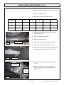
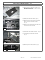
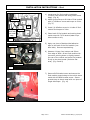
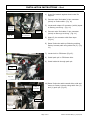
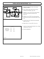
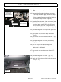
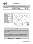
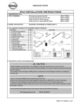
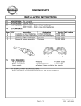
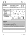
GENUINE PARTS
INSTALLATION INSTRUCTIONS
1.
2.
3.
DESCRIPTION:
APPLICATION:
PART NUMBER:
iPod
GT-R (2009 ~)
iPod main kit-
999U7 DV000
4.
KIT CONTENTS: (999U7 DV000)
Item
QTY
Description
1
2
3
4
5
6
7
8
9
10
11
12
5.
6.
1
1
1
1
1
6
1
10
1
2
1
1
Service Part Number
Use factory SP for 284H1 1BA0A
Use factory SP for 284H2 9N00A
999U7 DV002SP
Part of 999U7 DV002SP
Part of 999U7 DV002SP
Part of 999U7 DV002SP
Part of 999U7 DV002SP
Part of 999U7 DV002SP
Part of 999U7 DV002SP
Part of 999U7 DV002SP
Part of 999U7 DV002SP
Part of 999U7 DV002SP
Interface Module
iPod Cable
Main iPod Cable
Ground Cable
Double Sided Adhesive Foam Tape
Single Sided Adhesive Foam Tape
Alcohol Wipe
8" Tie Straps
Grommet
M5 x 8 Screw
Cable Tie Panel Mount
Operation Manual
TOOLS REQUIRED:
● PGF stick
● Plastic pry bar
● Flash Removal
● Tape measure
● Philips #2
● Torx (T-20)
● Portable Light
● Drill, 3mm (1/8") bit,10mm (3/8") bit
PRE-INSTALLATION CAUTIONS/NOTES:
● Dealer Installation Recommended. Instructions refer to Service Manual.
● This part is to be installed at a surface temperature of 65-100°F.
CAUTION
● Glove box has many hidden screws. When all screws have been removed, glove box comes out easily.
● Maximum M5 screw length is 8 mm. The use of longer screws will damage the iPod module.
● Do not touch or contaminate the cleaned sheet metal or the adhesive tape on the iPod module to prevent the
adhesion strength from being reduced.
Page 1 of 8
999U7 DV100II REV [1] 07/21/08
INSTALLATION INSTRUCTIONS - iPod
7.
VEHICLE PREPARATION:
1) Verify vehicle shift lever is in the "P" position.
2) Apply the parking brake.
3) Record the customer radio presets.
Preset
1
2
3
4
5
6
A
B
C
4) Move the front passenger seat to the most
rearward position.
5) Turn the ignition switch OFF.
6) Open the engine hood.
Kicking Plate
7) Disconnect the negative battery terminal.
Fig. 1
8) Remove RH side kicking plate. (Fig. 1)
9) Remove Plastic nut from RH side dash panel
and remove RH side dash panel. (Fig. 2)
Fig. 2
Plastic Nut
10) Loosen 12" of weather strip in circled area.
(Fig. 3)
Arrows indicate
Pry Points
Loosen
weather
strip
11) Remove RH defrost panel by applying
pressure at pry points as shown with PGF
stick. (Fig. 3)
Fig. 3
Page 2 of 8
999U7 DV100II REV [1] 07/21/08
INSTALLATION INSTRUCTIONS - iPod
12) Remove glove box outer by moving side to
side and pulling up. (Fig. 4). Refer to service
manual for more details.
Fig. 4
13) Detach glove box outer tether. (Fig. 5)
14) Remove glove box inner screws (10 places).
Be sure to remove all hidden screws.
(Fig. 5).
Tether
15) Glove box inner should come out easily once
all screws have been removed.
Fig. 5
16) Disconnect trunk release connector. (Fig. 6)
17) Disconnect glove box lamp connector.
(Fig. 6)
Disconnect harness
Fig. 6
18) Remove glove box lamp system. (Fig. 7)
Fig. 7
Remove lamp system
Page 3 of 8
999U7 DV100II REV [1] 07/21/08
INSTALLATION INSTRUCTIONS - iPod
8.
iPod MODULE INSTALLATION:
1) Locate area for iPod module installation
(100mm from bottom and along sheet metal
edge). (Fig. 8)
2) Attach ground strap to RH side of iPod module
with (1) M5x8mm screw and torque to 2 Nm.
(Fig. 9)
iPod Module
BCM
Align
module with
sheet metal
edge
100 mm
4) Clean back of iPod module and mating sheet
metal area with 70/30 alcohol/water wipe.
Allow surface to dry.
Fig. 8
5) Apply one piece of double-sided adhesive
tape to the back of the iPod module (nonlabel side). Remove tape backing.
iPod Module
BCM
100 mm
3) Install (1) M5x8mm screw in LH side of iPod
module and torque to 2 Nm.
6) Measure 100mm from bottom and 50mm
from edge of BCM. Orient iPod module with
connector pointing down or slightly toward
the rear of the vehicle and press iPod module
firmly to the sheet metal (maximize flat
area). (Fig. 8 and 9)
Ground Strap
Fig. 9
7) Remove BCM bracket screw and secure the
iPod module ground strap to the vehicle sheet
metal with the BCM bracket screw. Secure
ground strap to sheet metal with one piece of
single sided tape. (Fig. 10)
Fig. 10
Page 4 of 8
999U7 DV100II REV [1] 07/21/08
INSTALLATION INSTRUCTIONS - iPod
9.
CABLE ROUTING:
1) Press iPod module against sheet metal for
support.
2) Connect main iPod cable 24 pin connector
(white) to iPod module. (Fig. 11)
iPod main
cable 24 pin
and 12 pin
connectors
Fig. 11
3) Locate and untape 12 connector (white) taped
to factory pre-wiring. (Fig. 11)
(2) Tie
Straps
Foam tape on 12
pin connectors
4) Connect main iPod cable 12 pin connector
(white) to factory pre-wiring. (Fig. 11)
5) Wrap 12 pin connector with foam tape.
(Fig 11)
6) Route iPod main cable up following existing
factory harness path using cable ties (2). (Fig
11)
7) Locate hole in CPM beam (Fig 12).
8) Install push pin in CPM beam hole.
9) Install cable tie through push pin.
CPM Beam
Hole
Fig. 12
Push pin and
tie strap in
cross beam
10) Route iPod main cable toward driver side and
secure to factory harness using cable ties (3)
and (1) push pin (Fig 13).
2 Tie Straps
Fig. 13
Page 5 of 8
999U7 DV100II REV [1] 07/21/08
INSTALLATION INSTRUCTIONS - iPod
10.
iPod CABLE INSTALLATION
3 mm Pilot
Hole (2)
1) Position the glove box inner so the lamp
opening is visible.
Vehicle rear 10 mm Hole
(2)
2) Place masking tape above lamp opening
toward rear of vehicle. (Fig. 14)
11 mm
11 mm
4 mm
Lamp
Opening
Masking
tape
Fig. 14
4 mm
3) Measure 11 mm (7/16") from lamp opening
and mark the center of the first hole.
(Fig. 14)
4) Measure 4 mm (5/32") from lamp opening
and mark the center of the second hole. (Fig.
14)
5) Drill two 3mm (1/8") pilot holes at marked
points. (Fig. 14)
6) Open holes to 10 mm (3/8"). (Fig. 14)
7) Smooth out opening with drill bit, file, or flash
removal tool. (Fig. 15)
Dashed line
area must be
removed
8) Remove masking tape.
Fig. 15
Page 6 of 8
999U7 DV100II REV [1] 07/21/08
INSTALLATION INSTRUCTIONS - iPod
9) Slit the grommet and place it on the iPod
cable.
Grommet slit
should point
toward vehicle
rear
Fig. 16
10) Connect the iPod cable black/grey connector
to the iPod main cable grey connector. Wrap
a piece of foam tape around the connectors
and tie strap the connectors and iPod cable to
the glove box lamp harness. (Fig. 16)
Vehicle rear
Apply foam tape
around connector
and secure with (1)
cable tie.
11) Pass the iPod connector (black connector) end
of the iPod cable through the rectangular
glove box lamp opening. Slide the grommet
into the 10mm (3/8") slot. The grommet slit
should point toward the vehicle rear. (Fig. 16)
12) Re-install the glove box lamp in the glove box
inner
13) Re-Connect the glove box lamp connectors
(Fig. 6)
14) Re-connect the trunk release connector. (Fig.
6)
15) Re-install the glove box inner (10 screws).
(Fig. 5)
16) Pull the excess iPod cable through the
grommet. Do not pull with excessive force or
cable could be damaged.
17) Re-connect the glove box outer tether. (Fig.
5)
18) Re-install the glove box outer. (Fig. 17)
19) Verify the iPod cable is visible inside the glove
box. (Fig. 17)
Fig. 17
Page 7 of 8
999U7 DV100II REV [1] 07/21/08
INSTALLATION INSTRUCTIONS - iPod
11.
TRIM INSTALLATION
1) Re-install RH side dash panel (forward of
kicking panel and forward corner of RH
footwell. Verify all harnesses are tucked and
secured properly.
2) Re-install the plastic nut for RH side dash
panel and front bracket.
3) Re-install the RH defrost and weather strip.
4) Re-install the RH side kicking plate. (Fig. 1).
Verify glove box and panels fit and finish.
12.
FUNCTIONAL VERIFICATION AND PACKAGING DISPOSITION
1) Re-connect battery negative terminal.
2) Verify the trunk release is operational
3) Verify the glove box lamp is operational
4) If available, key on vehicle and connect iPod
to cable. Press aux mode button until iPod
mode is selected. iPod should play music.
5) Program customer's radio presets to the
recorded settings. Verify radio presets
function properly.
6) Confirm vehicle systems operate properly. If
equipped, verify sunroof operation. Refer to
Service Manual for requirements.
7) Place iPod operation manual in glove box and
close glove box.
8) Inspect the vehicle interior and exterior for
damage.
9) Properly dispose (recycle if possible) iPod kit
packaging, installation instructions, and extra
parts.
Page 8 of 8
999U7 DV100II REV [1] 07/21/08