1
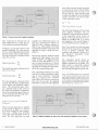
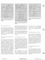
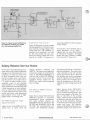
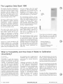
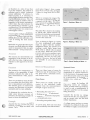
HEWLETT
PACKARD
SERVICE INFORMATION FROM HEWLETT-PACKARD
2nd Quarter 1990
Operational Ampllifier Basics
Introduction
It can be mathematically shown that
if an amplifier has:
I
I
I
I
an infinite high gain,
an infinite bandwidth,
an infinite high input impedance,
and
a zero output impedance,
then its characteristics can be totally
determined by external components
connected in feedback loops. Such an
”ideal” operational amplifier (op
amp) is shown in Figure 1. Since RIN
is infinite, there is no current flow into
either input terminal and the differential input voltage is zero. If there is
an output voltage Eo present, it can
only be the result of an infinitesimal
voltage at the input. These are
theoretical considerations only.
Figure 1. “Ideal” Operational Amplifier
Pub. No. 5952-3458
The op amp is, therefore, an ideal
building block for all kinds of analog
tasks. In practice, no single characteristic listed above can be fully
achieved. The values that can be practically obtained are nevertheless such
that the resulting performance is
extremely useful.
Op Amp Fundamentals
An op amp is a very high gain dc
amplifier and usually has voltage
gains in the range of 20,000 to
1,000,000. The detailed schematic
symbol of an op amp is shown in
Figure 2a with the simplified symbol
shown in Figure 2b.
As shown in Figure 2a, the -input
of the op amp is called the inverting
input, and the +input is called the
noninverting input. If an input signal
is applied to the -input, with +input
grounded, the polarity of the output
signal will be opposite to that of the
input signal. If an input signal is
applied to the +input, with the -input grounded, the polarity of the output signal will be the same as that of
the input signal. For an ac signal, this
means that the output of the op amp
will be 180 degrees out of phase with
a signal applied to the - input, but in
phase with a signal applied to the
finput.
WWW.HPARCHIVE.COM
Ideal Op Amps With Negative
Feedback
The most common op amp circuit configuration uses two external components: 1) an input component and 2)
a feedback component (see Figure 3).
When the feedback component is between the op amp output and the
-input, the circuit is said to have
negative feedback. When the feed-
V+
Power Supply
1 Input
n ”
Ioninverting
Input
e
~
i
n
g
I
~
output
Power
Supply
Ground
Fig. 2a. Detailed schematic.
0
Fig. 2b Simplified schematic.
Figure 2. Op-amp schematic symbols
Hewlett-Packard 1990
sum of the currents toward any point
in a network is zero) to the invertinginput terminal of the op amp, it can
be seen that the input current must
be equal and opposite to the feedback
current. Extensive use will be made
of this important result:
Feedback
Component
IIN-
IFB = -IIN
I
1
Figure 3. Op amp circuit with negative feedback
back component is between the op
amp output and the +input, the circuit is said to have positive feedback.
In Figure 3, an op amp is shown with
negative feedback. EIN is the inut signal, VI, is the differential input to the
op amp, and Eo is the op amp output.
The open loop gain is defined as the
ratio of E, to VIN:
Open-Loop Gain
=
EO
-
The closed-loop gain is defined as the
ratio of Eo to EIN:
Closed-Loop Gain
EO
= -
The open-loop gain is the gain of the
op amp and this gain is independent
of the input and feedback components. The closed-loop gain, however, depends only on the values of
the input and feedback components
when the closed-loop gain of the circuit is much less than the large openloop gain of the op amp.
Input Current and Feedback
Current
When an input signal (EIN) is applied
to the circuit of Figure 3, a current
(IIN) flows through the input component and a voltage (VIN) develops
across the input terminals of the op
amp. The very high gain op amp
2
BENCH BRIEFS
amplifies the differential input voltage (VIN) producing an output voltage (E,) with a polarity opposite to
that of VIN. This output is fed back
through the feedback component and
opposes the input voltage that produced it.
The Equivalent Circuit
The schematic diagram of the op amp
with negative feedback may be
simplified, using the previous results,
to the equivalent circuit shown in
Figure 4.The equivalent circuit is obtained by recalling that I,, is equal
and opposite to I,, and so Figure 3
can be relabeled as shown in Figure 4.
Since VI, is nearly zero, the inverting
input of the op amp can be considered
to be at ground potential. This
simplifies the diagram of Figure 4 to
the important equivalent circuit
shown in Figure 5.
Because the negative feedback signal
opposes the input signal, VIN is very
small. Therefore, the higher the gain
of the op amp, the smaller is VIN. In
fact, for some calculations, VIN can be
assumed equal to zero and the inverting input at virtually the same potential as the noninverting input.
The equivalent circuit shown in
Figure 5 shows why op amps with
negative feedback are so useful. The
input circuit is electrically isolated
from the output circuit, yet the current flowing through the input com-
The relationship between the input
current (IIN)and the feedback current
(IFB) is most important. Assuming
that VI, is equal to zero*, it follows
from Ohm's law that no current can
flow into the op amp. By applying
Kirchhoff's current law (the algebraic
'If V,, were actually equal to zero, the output
of the op amp would also be zero and the op
amp would be useless. In reality, VI, is a very
small voltage (usually less than a millivolt).But,
for the purpose of calculating input and feedback currents, very little error is introduced by
approximating V,, as equal to zero.
tlN ---b
1
'IN-
l------
I
I--
Input
Component
El,
i
P
I
r-
Figure 4. Negative feedback op amp circuit with equivalent feedback current shown
WWW.HPARCHIVE.COM
2ND QUARTER 1990
equal to the E,, source impedance for
balancing purposes of the differential
input stage.
Component
Component
The Inverting Op Amp
I
Figure 5. Equivalent circuit of Figure 4
r
ponent dictates what current must
flow through the feedback component. By choosing different input and
feedback components, different circuit functions can be performed. The
circuit functions listed in Table 1 will
be discussed later in this article.
Table 1. Table of Circuit Functions
Figure 6. Simple voltage divider
Figure 7. Simple voltage divider set at
50 percent
Figures 6 and 7 illustrate a very simple
concept in conjunction with an op
amp. The potentiometer P is used as
a variable voltage divider and the voltage delivered to the load is in a linear
ratio with the shaft rotation. This will
only be the case if the load is an infinite resistance, or is very high in comparison to the resistance of P. As an
example, if P and the load are each
10 kilohms and P is set at 50 percent,
the division ratio will not be 1/2 but
2/5, as shown in Figure 7.
feedback. An op amp connected in
this way is often referred to as a voltage
follower or an impedance converter.
An additional characteristic that is important for an op amp is stability. If
the input is zero, the output will also
be zero. The op amp must be free of
drift or offset voltage.
If an op amp is connected between
the movable contact of P and the load
as shown in Figure 8, the op amp will
provide perfect isolation. The op amp
must have a closed loop gain of one.
This is possible with a 100 percent
In the configuration shown in Figure
9, E,, and E, are in phase. The closed
loop gain is controlled by the ratio of
R, and R,. If R, = 0, then the amplifier
is simply a voltage follower and R,
becomes meaningless. However, in
practical applications, it will be made
2ND QUARTER 1990
Circuit
Function
1
..I.
.
Input
:omponents
Resistor
Resistor
Capacitor
EI, and E, are inverted as is indicated
by the negative sign for the gain (see
Figure 10). R3may be included instead
of a ground connection of the noninverting input only because of a less
than ideal amplifier (less than infinite
input impedance). R, should be equal
to R,, again for balancing purposes.
If the characteristics are close enough
to ideal, then input B is at ground
level. By definition, input A must also
be at ground level since there shall be
no potential difference between inputs A and B. Point A is called a virtual ground.
Figure 8. Simple voltage divider with op
amp providing isolation
The Noninverting Op Amp
WWW.HPARCHIVE.COM
GAIN = 1 FOR R, = 0 OR R, = co
R,,
CO
I, = 1, INDEPENDENT OF R2
Figure 9. Simple noninverting op amp
BENCH BRIEFS 3
I
Figure 12. Simple differential operational
amplifier
Figure 10. Simple inverting operational
amplifier
Figure 11. Simple summing operational
amplifier
The Summing Op Amp
The summing op amp shown in
Figure 11 is simply an inverting op
amp with multiple inputs. Since input
A is a virtual ground, there can be no
current flowing over A from one input
into another input. The total input
current is I, = I,. The number of
inputs is only limited by practical
considerations.
The Differential (Subtracting)
OP Amp
If the same signal is applied to both
the +input and the -input of the op
amp shown in Figure 12, the two
amplified output signals will be 180
degrees out of phase and will completely cancel each other. Since the
op amp responds only to differences
between its two inputs, it is said to
be a differential amplifier. The voltage
difference between the +input and
the -input is called the differential
input voltage. Since a differential
amplifier amplifies only the differential input voltage and is unaffected by
signals common to both inputs, it is
said to have common-mode rejection.
Common-mode rejection can be very
useful, for example, when measuring
4
BENCH BRIEFS
small signals in the presence of 60
Hertz noise. The 60 Hertz noise common to both inputs is rejected and the
op amp amplifies only the small signal
difference between the two inputs.
Note that an ideal differential op amp
produces neither a differential-mode
nor a common-mode output in response to a common-mode interference input.
The Integrating Op Amp
The simple integrating op amp shown
in Figure 13produces an output signal
proportional to the integral of the
input signal and time variable of the
resistance and capacitance charging
rate. The capacitor connected across
the input and output of the inverting
op amp improves the performance by
what is called the Miller Effect. The
Miller Effect says that a capacitor connected as shown appears to the input
as being multiplied by the gain of the
amplifier.
If R = 1 megohm and C = 1 microfarad, according to the formula
shown in the figure, Eo will increase
at a rate of 1volt per second, positive
or negative, depending on the polar-
WWW.HPARCHIVE.COM
ity of EIN. If E,, is a symmetrical
square wave, Eo will be a triangle
wave. For E,, = sin X the output is
-cos X. The output leads the ;nput
by 90".
"\
The Differentiator Op Amp
As shown in Figure 14, Eo is proportional to the rate of change of the
input voltage. A dc input will make
Eo = 0 because of the blocking
capacitor C . A square wave at the
input will produce a spike at the output triggered by the leading and trailing edges of the input signal. Because
the top of the square wave is a constant value, the differential factor is
zero and the integrating capacitor discharges towards zero.
The Logarithmic Converter
OP Amp
If a nonlinear element such as a transistor is connected into the feedback
path as shown in Figure 15, E,, versus
Eo follows a nonlinear function. The
base-emitter junction of Q, represents
the logarithmic element in the feedback loop.
2ND QUARTER 1990
-3
I
Figure 13. Simple integrating operational amplifier
The Antilog O p Amp
By placing the nonlinear element in
the input path as shown in Figure 16,
the circuit becomes an antilog converter. For a logarithmic input E*,, the
output E, will be a linear signal.
Figure 14. Simple differentiator
operational amplifier
Multiplication (Division) With
Log-Antilog Operational
Amplifiers
Since log A + log B = log AB, and
log A - log B = log A/B, a circuit
using two log converters and a summing (subtracting) amplifier, followed by an antilog converter, will
output the product or the division of
the two input signals. Figure 17 illustrates the circuit for multiplication.
Figure 15. Simple logarithmic converter
operational amplifier
Figure 16. Simple antilog op amp
SUMMING
ANTILOG AMPLIFIER
LOG A
+
LOG 0
Figure 17. Multiplication circuit using log and antilog operational amplifiers
2ND QUARTER 1990
WWW.HPARCHIVE.COM
BENCH BRIEFS
5
TUNECONTROL
POWER SUPPLY
- 5 VOLT ADJ
SWEEP
v
TUNE BUFFER
R21
1 0 ~ SWEEP
RlO
6
+ TUNE
5000
OUT
--
- 15V
Figure 18. Typical op amp application as
an impedance converter (&), isolator
(U,), and summing amplifier (U,)
Typical Op Amp Circuit
Figure 18 illustrates a typical example
op amp application. The task is to produce and mix a tuning voltage with a
sweep ramp for a YIG oscillator. U6
operates as an impedance converter
for the zener diode CR1. Rloo produces the tuning voltage that is isolated by U7.Finally, U4operates as a
summing amplifier for the tuning and
sweep voltage.
If you desire a more detailed and indepth discussion of op amps, I
suggest that you read Understanding
IC Operational Amplifiers, by Roger
Melen and Harry Garland, available
0
from Howard W. Sams & Co.
Safety-Related Service Notes
Service notes from HP relating to personal safety and possible equipment
damage are of vital importance to our
customers. To make you more aware
of these important notes, they are
printed on paper with a red border,
and the service note number has an
"4" suffix. In order to make you immediately aware of any potential
safety problems, we are highlighting
safety-related service notes here with
a brief description of each problem.
Also, in order to draw your attention
to safety-related service notes in the
service note index, each appropriate
safety-related service note is highlighted with a contrasting color.
HP E2500 Frequency Agile
Signal Simulator
Safety Service Note E2500A-01-S describes how to safety check the
6
BENCH BRIEFS
routine dielectric withstand test
(HIPOT). This service note applies to
instruments within the serial number
range of 2845A00101/2935A00114. If
you own one of these HP E2500As,
you may return it to your nearest HP
Customer Service Center for the
HIPOT test, which will be conducted
free of charge.
wires being improperly connected inside the transformer. The result is that
when operating on the 220 volt line
setting, the line fuse blows. Both the
line module and power transformer
must be replaced at an HP Customer
Service Center. Do not attempt to rewire the transformer as this will invalidate the color coding used on the
wires.
HP 5347A & 5348A Counter/
Power Meters
Safety Service Notes 5347A-03A-S
and 5348A-03A-S concern the removal of unsafe carrying straps. This
service note applies to all units. The
clips on the ends of the carrying
straps, which are part of Option 060
are defective and may fail in the normal use of the instrument. Damage
to the instrument and/or injury to personnel may occur. The defective
straps are identifiable as being non-adjustable in length. Also, there is con-
Safety Service Notes 5347A-02-S and
5348A-02-S describe an incorrectly
manufactured power transformer.
The serial numbers affected are
2924A00101-158 and 160-170 for the
HP 5347 and 2924A00101-120 for the
HP 5348. The manufacturing error
concerns the transformer primary
WWW.HPARCHIVE.COM
2ND QUARTER 1990
1
cern over the strength of the front
panel casting at the carrying strap
holes. Mis-application of a customer
furnished strap may apply sufficient
leverage by weight of the instrument
to cause breakage. No strap or other
carrying appliance should be connected at these points.
Please remove the non-adjustable
strap from the unit and return it to
the following address. A new adjustable strap will be returned to you, in
addition to a pair of plastic plugs to
block the front panel carrying strap
attachment holes.
Joe Dore 52U/19
Hewlett-Packard Co.
5301 Stevens Creek Blvd.
Santa Clara, CA 95052-8059
The solution to making the instrument portable is the design of a soft
carrying case. This case has been designed to enhance portability with
tough cordura nylon double-stitched
construction that is padded on all six
sides. The permanently attached adjustable strap provides a much safer
means of carrying the product and allows easy measurements with the
unit suspended from the shoulder.
If you originally purchased the product with the Option 060 portability option and have returned the strap as
previously requested, you will receive
this new soft carrying case at no
charge.
HP 8340A/B Synthesized
Sweepers
HP 8341A/B Synthesized
Sweepers
HI’ 8719A Network Analyzers
HI’ 8720A/BNetwork Analyzers
The following Safety Service Notes
describe possible injury from falling
instruments due to damaged front
panel handles.
8720A-054, 872OB-Ol-S, 8719A-Ol-S,
8340A-30-S, 8340B-30-S, 8341A-30-S,
8341B-30-S
If damaged handles are used to lift or
support the instrument, the handles
will break causing the instrument to
fall, possibly resulting in personal injury. Exercise caution when using the
front handles to lift the instrument.
The damaged handles will be replaced at an HP Customer Service
Center, or you may order the front
handle replacement kit free of charge
(HP PIN 5062-3990) and perform the
replacement following the instructions in the product’s service manual.
HP 8657B Synthesized Signal
Generator
Safety Service Note 86578-01-S describes a possible shock hazard that
may exist if the instrument’s toroidal
mains transformer’s insulation has
been damaged by the A14 assembly’s
heatsink. The units affected are
within the following serial number
ranges:
mains transformer’s insulation.
If your instrument is one of the above,
please return the unit to an HP Customer Service Center for repair.
HP 8757C/E Scalar Network
Analyzer
Safety Service Note 8757C/E-02-S describes a possible defective lithium
battery contained on the CPU board
of the instrument. The battery may
leak electrolyte and damage the
board. Symptoms include yellowing
around the battery or in some cases,
corrosion of the board and other
boards in close proximity. The Safety
Service Note contains a list of applicable serial numbers. Please return
your unit to the nearest HP Customer
Service Center for repair.
HP 85620A Mass Memory
Module
Safety Service Note 85620A-03-S describes a possible defective lithium
battery contained on the mass memory module of the instrument. The
battery may leak electrolyte and damage the board. Symptoms include yellowing around the battery or in some
cases, corrosion of the board and
other boards in close proximity. The
serial number range of affected instruments is 0000A00000/3003A00604. If
you possess one of the affected units,
please return it to the nearest HP Customer Service Center for repair.
HP 86792A Agile Upconverter
If you did not order Option 060 and
wish to buy the soft carrying case,
order HP P/N 05348-60214. The price
is $295 U.S. list.
r
For those customers ordering the instrument and specifying the portability option, please be advised that Option 060 has been discontinued. The
portability option is now the soft carrying case and is listed as Option 070,
$295 U.S. list.
2ND QUARTER 1990
The HP 86578 may present a shock
hazard only if the following conditions exists:
0
The mains transformer has not been
manufactured by “NUVOTEM”
and
The A14 heatsink has damaged the
WWW.HPARCHIVE.COM
Safety Service Note 86792A-02-S describes how to safety check the
routine dielectric withstand test
(HIPOT). This service note applies to
instruments within the serial number
range of 2814A00105/2814A00108. If
you own an HP 86792A within the
serial number range listed, you may
return it to your nearest HP Customer
Service Center for the HIPOT test,
which will be conducted free of
0
charge.
BENCH BRIEFS
7
The Logistics Data Book 1990
The Logistics Data Book is designed to
assist Hewlett-Packard's government
customers with their logistics needs
associated with the support of HI'
products. Information is drawn from
HI' records and Department of Defense information. It reflects logistics
actions through October, 1989.
The types of HP products covered in
this publication include electronic
components, medical instruments
and systems, computer equipment,
calculators, instruments and systems
for chemical analysis, and electronic
test and measuring systems.
The intent of the Logistics Data Book
is to include HP model numbers and
their various options that are purchased by government customers.
Additional information on all HP
parts having National Stock Numbers
may be found in the microfiche NSN/
HI' Cross Reference (Publication No.
5957-4171).
Options are usually identified in HP
product literature by a three-digit
number following the model number
(e.g., HP 1234A Option 003). Other
options may be designated as a letter
and two numbers after the model
number (e.g., HP 1234A OptionH02).
Modifications and systems may be
identified in HP literature with a
single alpha and two digits preceding
the model number (e.g., E12-1234A).
For procurement purposes, all options and modifications in this book
follow the model numbers and are
connected to them by hyphens (e.g.,
1234-001 and 1234A-E12). Where
space is limited, option numbers may
be shortened to less than three characters (e.g., 1234A-01-02-EI2).
0
0
Model numbers are arranged in typical computer sequence (i.e., left-justified, alpha-numeric sequence) so
that all the "1s" (Model 1, 11, 111,
1111, etc.) are listed before the "2s"
(Model 2, 22, 2222, etc.).
The Hewlett-Packard office nearest
you will be pleased to work with you
on procurement matters. Also note
that the most currently-produced HP
products are on GSA federal supply
schedule multi-award contracts, and
that GSA catalogs are available from
your HP office. To order your Logistics
Data Book, specify publication no.
5954-7744.
If you h ve any comments or suggestions about how we can make the
Logistics Data Book more useful to you,
please let us know by writing to:
Hewlett-Packard Co.
U.S. Field Operations
John Cloutier
19320 Pruneridge Avenue
Cupertino, CA 95014
,"\
0
What is Traceability and How Does It Relate to Calibration
Uncertainty?
Jim Becktold
Hewlet t-Packard
Traceability is proof that measurements can be attributed to a national
standard. The process involves the
"tracing" of measurement comparisons made between the instrument
used and the national laboratory.
Technically, traceability involves the
ability to quantify the measurement
errors present in the test or measurement process in terms of the national
standards. Agencies require us to objectively demonstrate that traceability
exists. Usually through a series of reports attesting to the calibration of the
instruments used in a test situation,
8
BENCH BRIEFS
the standards used to calibrate these
standards, and so on back to the reports issued by national laboratory
standards.
Calibration uncertainty is the ability
to quantify the error sources present
in the calibration measurement.
Knowing that the act of making measurements is experimental, there
have to be some guidelines that tell
the person doing the measurement
that the job is being performed satisfactorily. A rule-of-thumb method
called the "accuracy ratio" is used in
many laboratories to determine
whether the uncertainty is reason-
WWW.HPARCHIVE.COM
able. The desired ratio of accuracy between a source instrument and one
to be calibrated is 1O:l. If this cannot
be met, it is permissible to reduce the
ratio downward to a lower limit of 4:l.
This ratio is calculated by dividing the
tolerance of the measurement to be
made (e.g., 5%) by the tolerance assigned to the instrument used to
make the measurement (e.g., 1%). In
this example of accuracy, the ratio
would be 5:1.
In some of today's instrumentation,
the instrument being calibrated is almost as accurate as the source device,
2ND QUARTER 1990
1
C
and therefore at a ratio of less than
4:l. In this situation, the method of
calibration used is called “enhanced
accuracy calibration.” To achieve enhanced accuracy it is necessary to
utilize a higher echelon standard during the calibration process. This will
provide as much as another order of
magnitude to the source equipment,
which widens the ratio between the
two instruments to maintain a good
confidence level. We recommend that
when you get below 4:1, contact your
metrologist for advice.
A more specific method of determining uncertainty involves understanding the types of errors that exist during measurement and calibration, and
ways of avoiding the most serious
ones.
But before we get into the three types
of errors, we should define two terms
used in measurement that are quite
often confused -accuracy and precision.
Accuracy
rp
The accuracy of a measurement is an
expression of the closeness of its result to the true value. A high accuracy
indicates a close approach to the true
value.
Precision
The precision of a measurement is a
measure of its repeatability. A high
precision indicates the ability to repeat measurements within narrow
limits.
each meter. Figure 1 shows a range
from 97.16 to 97.24 volts, and Figure
2 shows a range from 99.1 to 100.7
volts.
When we compare the ranges of the
two meters we find that meter #1 has
a spread of 0.08 volts and meter #2
has a spread of 1.6 volts. This defines
meter #1 as having 20 times the precision than meter #2 has (i.e., 1.6/.08
= 20).
But meter #2 is closer in its readings
to 100.00 volts, which indicates that
precision by itself does not necessarily
produce accuracy. Meter #2 is more
accurate than meter #l.
Now, as shown in Figure 3, if meter
#1 were recalibrated, with adjustment, to agree with the ”perfect”
calibration source, the spread of its
readings would likely range from
99.96 volts to 100.04 volts (a spread
of 0.08 volts). While this shows that
precision and accuracy combine to provide greater confidence in the use of an
instrument, the two are truly independent. However, the best of both
are desirable in any measurement
situation.
To eliminate the confusion that normally exists between accuracy and
precision, the following example will
serve to show the difference.
r
L
Figure 3. Altered Reading of Meter #1
Systematic Errors
There are three types of errors by
which you may be confronted. They
are: gross errors, systematic errors,
and random errors.
Systematic errors relate to the instrumentation or external influences
to the instruments. Systematic errors
cause the measured value to be offset
by a fixed amount, as contrasted to
random errors, which are bipolar in
nature.
These errors are strictly under the
control of the individual, totally
separate from the instrumentation.
Example of gross errors are:
-
1
Misreading the instruments
Making an incorrect adjustment
Applying instruments improperly
Example
-.
Assume that two meters are used to
measure a perfect 100.00 volt power
source. Ten readings are taken with
As can be seen, these are errors that
can be avoided by care and attention.
2ND QUARTER 1990
Figure 2. Reading of Meter #2
Errors in Measurement
Gross Errors
These two definitions form the basis
for everything else that follows relative to measurement and calibration.
The ultimate goal is to achieve both
accuracy and precision in every measurement and in every calibration.
Figure 1. Reading of Meter #1
1
Computational errors
Recording interpolated data
WWW.HPARCHIVE.COM
One example may be loading. All
measuring systems are intrusive.
That is, no matter what type of device
is used to make a measurement, it
will have some effect on the system
being measured.
Consider the fact that no voltage
source has the ideal zero impedance,
and no current source has the ideal
infinite impedance.
A voltage source may have a source
resistance of as little as 0.01 ohm, and
the ability to supply current of 25 mil-
BENCH BRIEFS
9
liamps at 10 volts output. The internal
voltage drop could then be 250 microvolts, which represents 25 ppm of the
10 volt output (0.0025%). In addition,
assume that the connecting leads
have 10 milliohms of resistance. The
voltage drop across the leads would
add another 250 microvolts of error,
or 25 ppm. These two elements alone
constitute an error of 50 ppm, or
0.005%. Note that the obvious way
to avoid these errors is to use 4-wire
remote sensing whenever the load is
less than 1 megohm.
Random Errors
These errors are indicated as a scatter
about an average when a multiple
number of measurements are taken.
This can be the result of variations in
the measuring system, or changes in
the quantity being measured.
Random uncertainties are of a type
that lend themselves to statistical
analysis, since they can be considered
to vary either positively or negatively
around the measured value. They are
due to totally unknown causes, and
are detectable when repeated measurements are made with a seemingly
constant set-up and consistent
technique by the user.
tions can be made regarding random
errors:
The closest value to the true value
is the mean value
1
It is likely that values close to the
mean value will be more numerous
than values that are far away from
the mean value
There are likely to be as many readings that lie above the mean value
as there are those that lie below the
mean value
An example may be a variation in impedance matching in high frequency
instruments due to changes in characteristics when the lead connectors are
removed and replaced. This may be
due to the wear, or contamination, of
BNC connectors, which are quite susceptible to this behavior.
It is the general nature of a measured
variable that there will be a distribution of values (both plus and minus)
around the true, or actual, value.
When a succession of measurements
are made which differ one from
another, some preliminary observa-
Note that it is never possible to know
the true value, since there will always
0
be some small error.
Important Notice about Service Notes
Service notes contain product-specific
service information for Hewlett-Packard’s electronic products. Subjects include product improvements, modifications, and procedures for troubleshooting, maintenance, and repair.
Service Notes are published as appropriate throughout the life of a
product. All new notes are announced in Bench Briefs.
Please note that Hewlett-Packard has
restructured the procedure for handling and distributing instrument-related service notes through Bench
Briefs and the microfiche program.
10 BENCH BRIEFS
Bench Briefs
If you want to order a service note,
refer to the list of service notes in the
index, find the service note number
belonging to the product you are interested in, and note the package
number. Use the form on the last page
of Bench Briefs to order the number
that appears in the ”service note package” column. You will receive a package of service notes that includes the
one you ordered.
Microfiche
Service notes are still available on
microfiche. The part numbers are:
WWW.HPARCHIVE.COM
Library
Update service
5951-6511
5951-6517
Please note that automatic shipments
of the update service will no longer
be made. If you want to continue to
receive quarterly updates to the
microfiche library, you must place a
new order during the first month of
each quarter (May, August, November, February). Note that inventory
will be purged at the end of each quarter.
Contact your local HP saledservice office for more information.
0
2ND QUARTER 1990
/7
Fast-Ship Icon
.
WWW.HPARCHIVE.COM
1
J
1
When you see the fast-ship icon
in the HP Direct Instruments Now catalog,
you know the quickest way to get the products listed is to call HP DIRECT before
4p.m. yourtime. Yourorderwillshipby7p.m. the sameday. Andget toyou
within seven working days.
HP DIRECT same-day shipping starts with warehouses in California and New
Jersey, where a full range of HP Test and Measurement products and computer
supplies are in stock 99.7% of the time. And it is supported by knowledgeable
sales consultants, staffing the dedicated toll-free phone lines, ready to help you
with your order.
Complete range of products - From BNC cables to protocol analyzers and
accessories.
Thorough documentation - Complete product, pricing and ordering
information in the HP DIRECT Instruments Now catalog.
Helpful, toll-free telephone ordering - Just call 800-538-8787 Monday
through Friday between 9 a.m. and 5 p.m. for assistance.
Same-dayshipping- Your order will ship within 24 hours of your verbal p.0.
Overnight delivery - Available for a nominal fee.
0 30-day money-back guarantee - If you’re not
completely satisfied, we’ll refund your money.
To order any of the products with the fast-ship icon, call
8011r-538-8787
HP DIRECT: 800-538-8787.
9
14
WWW.HPARCHIVE.COM
When you know what you need, and you need it ASAP, call our dedicated,toll-free
number between 9 a.m. and 5 p.m. your time. Knowledgeable sales consultants are standing by,
ready to take your order and ship it out the very same day, at no additional charge. And get it to you within
seven business days. If that’s not fast enough, we can arrange for overnight delivery. We’re in
stock 99.7% of the time.
What are you waiting for? Send in this card for your free HP DIRECT lnstruments Now
catalog. Start getting the same quality Hewlett-Packard instruments and basic test equipment
you’re used to-only faster.
Name Mr./Ms./Dr.
Rush Me A Free MB DIRECT
Instruments Pow c8Wog!
Company
0Add me to your mailing list and send me an
City/StatelZip
HP DIRECT InstrumentsNow catalog right away.
Telephone (
Dept.lBldg./Mail Stop
1
Ext.
Tell us about yourself.
Numberof peopleat your business location:
Which electronic test instrumentdo you use/specify/buy:
00 0 I use these products in my job.
03 0Iam a purchasingagent.
01 0 1-49
02 0 50-249
03 0 250-499
HP
0015 0
0016 0
0017
0018 0
0019 0
0008 0
0025 0
0020 0
0013
0005 0
0003 0
0009 0
0014 0
0004 0
0021 0
0023 0
04 0500-999
05 0 1000+
Check the deoartment AND title which closest describe your position:
Department
20 0 Engineering
20 0R&D
20 0Test
A0 0Quality Assurance
10 0 Manufacturing
40 0 Purchasing
50 0 Service
90 0Data Processing
BO 0 Education
0 Other
Title
08 0 Electronic Engineer
OA 0 Mechanical Engineer
02 0Technical Staff
07 0Technician
OB 0 TechnicalSupervisorlManager
OC 0 Purchasing Agent/Buyer
OD 0Administrative Manager
05 0 OwnerlPrincipal
OE 0Programmer
OF 0 Educator
0 Other
WWW.1
,iRCHIVE.COM
Non-HP
A015 0DVMlDMMs
A016 0Counters
A017 0Oscilloscopes
A018 0 PulselFunctionGenerators
A019 0 Power Supplies
A008 0Logic Analyzers
A025 0Board Test Systems
A020 MicroprocessorDevelopmentSystems
A013 0 Componentand SemiconductorAnalyzers
A005 0 Data andlor TelecommunicationsTesters
A003 0 RF and MicrowaveAnalyzers
A009 0 Microwave Power Meters
A014 0Vibration Analyzers
A004 DataAcquisition and Control
A021 0X-Y and Strip Chart Recorders
A023 0 Other
m3
c
The next time you need basic test and measurement products in a hurry, reach for an Instruments Now catalog. Complete
product, pricing and ordering information at your fingertips. Product number and alphabetical indexes make it quick and easy to find
the instruments you need. Full product descriptions, photographs,
flow charts, specifications, compatibility and selection guides
help you choose the best models for your application.
The Instruments Now catalog even includes new HP
products which may not be available in other HP catalogs!
FIRSTCLASS MAIL
PERMIT NO. 1478
SUNNYVALE, CA
I
I
I
I
I
I
POSTAGE WILL BE PAID BY ADDRESSEE
I
I
I
I
Hewlett-Packard Company
HP DIRECT
PO.Box 611298
San Jose CA 951 16-9890
I
I
llllllllllllllllll~ll~llll~llllllllllll,lll~~ll,llll
WWW. HPARCHIVE.COM
r
1990 Bench Briefs’ Instrument
Service Note Index
SN
SN
Type No.
7
3
MA
MR
MR
MR
IO
IO
IO
IO
IO
IO
MR
IO
MR
IO
MA
IO
SA
MR
IO
IO
IO
IO
IO
IO
IO
IO
IO
IO
IO
IO
IO
IO
MA
IO
IO
MA
IO
MA
IO
MR
MR
436A-16B
437B-03
437B-04
438A-10
1630A/D/G-14
163lA/D/G-14
165OA-09
1650B-01
165lA-09
1651B-01
3314A-03
3562A-11
3563A-01
3577A-14
3586A/B/C-13
3586A/B/C-14
3588A-01-S
3588A-02
3708A-17
3708A-18
3708A-19
3709B-04
3746A-34A
3746A-35
3746A-36
3776A-36
3776A-37
3776B-44
3779A-61
3779A-62
3779B-65
3779C-12C
3779c-43
3779c-44
3779D-12C
3779D-47
3779D-48
3787B-04E
3787B-09
3787B-10
3788A-01
2ND QUARTER 1990
Abstract
Service Note
Package
017
Recommended replacement display driver assembly
019
Modification to prevent erroneous power meter readings
020
Mod. to overvoltage protection circuit
Recommended A4C14 and A4C16 capacitor replacement to improve performance 017
021
Display system components available as a matched set (2090-0227)
021
Display system components available as a matched set (2090-0227)
017
Repair procedure for POD cable connectors J1-J5 (HP P/N 1251-8158)
017
Repair procedure for POD cable connectors J1-J5 (HP P/N 1251-8158)
017
Repair procedure for POD cable connectors J1-J5 (HP P/N 1251-8158)
017
Repair procedure for POD.cable connectors J1-J5 (HP P/N 1251-8158)
020
Mod. to correct improperly crimped cooling fan power leads
019
Instructions on how to service the HP 3562A Signal Analyzer with Option 063
022
Modification prevents instrument lock-up when using systhesis table
022
Required modification when replacing U13 on the A1 board
023
Modification available when replacing U1 and U29 on A61 board
023
Instructions on removing the internal Ni-cad battery for extended storage
022
Notification that the fuse label contains the wrong replacement fuse information
022
Metal flakes settling on the motherboard may cause intermittent H/Werrors
017
Semi-automatic performance test for the HP 3708A
019
Preferred repl. for capacitor A501C5 on the power supply high current assy.
021
Preferred replacement for D/A Converter A204U7 on the Var. Gain Cntl. Assy.
019
Preferred repl. for the Mod. Scheme Switch A3S2 on the microprocessor assy.
017
Preferred repl. for the Fract. N cir. A3OU16) on the Fract. N divided by N assy.
017
Changes to the 3.1 kHz channel filter adjustment
019
Preferred repl. for the 50 MHz crystal (A40Y90) on the A40 Frequency Ref. Assy.
019
Preferred repl. of transistorsA7Q21 and A7Q22
021
Preferred replacement of A3U33 and A204U47
021
Preferred replacement of A3U33 and A204U47
020
Preferred replacement for EPROMS A24, U31 and U41
Firmware upgrades
021
Firmware upgrades
021
Preferred repl. board assemblies that comply with VDE specifications
019
019
Small modification required when replacing A16 Assembly
021
Alternative recommended test equipment for performance tests
Preferred repl. board assemblies that comply with VDE specifications
019
019
Small modification required when replacing A16 Assembly
021
Alternative recommended test equipment for performance tests
019
Newer features can be retrofitted to earlier 3787B instruments
Notification of firmware updates
019
020
Mod. to eliminate crosstalk when performing loopback in Nearpar mode
Modification to prevent synchronization loss while measuring code errors on live data 022
WWW.HPARCHIVE.COM
BENCH BRIEFS 11
SN
SN
Type No.
IO
MA
MA
IO
IO
IO
MA
IO
MR
MR
MA
MR
MR
MR
MA
MR
MR
MR
MR
MA
MR
MR
MR
IO
MA
MR
MA
MR
MR
MR
MR
IO
IO
IO
IO
IO
IO
IO
IO
MR
IO
MA
MA
MA
MA
MA
IO
3789B-03
3789B-04A
3789B-05A
3789B-07
3789B-08
3789B-09
3789B-10
3789B-11
4062C-02A
4062C-02
4062C-03
4062C-04
4062UX-02A
4062UX-02
4062UX-03
4062UX-04
4142B-04A
4142B-04
4142B-05
4142B-06
4145A-13
4145B-04
4145B-05
4193A-04
4194A-09
4195A-05
4195A-06
4195A-07
4195A-08
4195A-09
4195A-10
426lA-01
4262A-18
4276A-05
4276A-06
4277A-09
4277A-10
4278A-06
4279A-01
428OA-08
4284A-09
4285A-01
4285A-02
4285A-03
4285A-04
4285A-05
4332A-01
Abstract
Service Note
Package
Retrofitting Option 010 (Printer) or Option 011 (Disk Drive)
Mod. to eliminate noise from HP 3789B Input Port
PROM update kit information
Firmwarehardware revisions and their impact on automated performance testing
Retrofitting Option 100 (Weco 477 connectors)
Retrofitting Option 200 (BNC connectors)
Adding enhancements to older units
Instructions to fit PROM upgrade kits
Rec. part repl. to prevent damage to the PSM by surge current
Recommended part replacement to prevent damage to the PSM by surge current
4142B upgrade for Revision 5.6 system software feature
SMU repl. to eliminate AFU test failures
Rec. part repl. to prevent damage to the PSM by surge current
Recommended part replacement to prevent damage to the PSM by surge current
4142B upgrade for Revision 5.6 system software feature
SMU repl. to eliminate AFU test failures
Rec. part repl. to prevent damage to the PSM by surge current
Recommended part replacement to prevent damage to the PSM by surge current
SMU repl. to eliminate AFU test failures
Mainframe upgrade for the HP 41422A HCU
Repl. PROMs prevent spikes when the SMU reaches compliance
Repl. PROMs prevent spikes when the SMU reaches compliance
Update Sys. Disk to Rev. 1.30 to improve perf. in HP-IB SRQ output function
Instructions for mounting a new diode on the HP 4193A A20 Power Supply Bd.
Modification to install Option 001 into a standard HP 4194A
Modification to remedy uneven display color
Modification to install Option 001 into a standard HP 4195A
Modification to eliminate spurious vert. white line on the CRT display
Mod. to improve the Seconmhird IF converter gain adjustment range
Mod. to improve source dc bias fullscale adjustments
Modification to improve the power sweep linearity
Instructions for mounting a new diode on the HP 426lA A9 Power Supply Bd.
Instructions for mounting a new diode on the HP 4262A A9 Power Supply Bd.
Instructions for mounting a new Ni-Cad battery on the mother board
Repair method for the A1 Logic Board
Instructions for mounting a new Ni-Cad battery on the mother board
Repair method for the A1 Logic Board
New EEPROM sockets added to new A7 boards - check before ordering new board
New EEPROM sockets added to new A7 boards - check before ordering new board
Mod. to correct noise on the dc power lines due to misloaded capacitors
Procedure for ordering new ROMless repl. brd. for the A7 CPU brd.
Modification to install Option 002 in a standard HP 4285A
Modification to install Option 201 in a standard HP 4285A
Modification to install Option 202 in a standard HP 5285A
Modification to install Option 301 in a standard HP 4285A
Modification to install Option 001 in a standard HP 4285A
Instructions for mounting a new diode on the HP 4332A A3 Power Supply Bd.
021
020
020
020
021
021
021
021
019
017
019
019
019
017
019
019
019
017
019
019
019
019
019
022
019
019
019
019
020
020
022
022
022
019
020
019
020
019
019
020
019
022
022
022
022
022
022
f"
T
r
f
12 BENCH BRIEFS
WWW.HPARCHIVE.COM
2ND QUARTER 1990
SN
SN
Type No.
7
IO
IO
MA
IO
IO
MR
MA
IO
IO
IO
IO
IO
IO
MR
IO
MR
MR
MR
MR
MA
IO
MR
MR
MR
MR
IO
IO
IO
MR
SA
PR
PS
MR
SA
PR
PS
MR
MA
MR
MR
MR
MR
IO
MR
IO
MR
MR
4934A-04
4934A-05
4934A-06
4934A-07
4934A-08
4934A-09
4936A-02B
4936A-11
4936A-12
4947A-11
4947A-12
495lA-21
4951B-05
4951C-1OA
4951C-12
4952A-08C
4952A-10A
4952A-llA
4952A-llC
4952A-12
4972A-05
4992A-01
506lA-21
5061B-02
5316B-02
5334B-04
5334B-05
5342A-26B
5347A-01
5347A-02-S
5347A-03-S
5347A-03A-S
5348A-01
5348A-02-S
5348A-03-S
5348A-03A-S
536lA-OlA
536lA-02A
5370B-03
5370B-04
537lA-02C
537lA-13A
5372A-01
5372A-02
606oA-01
606oA-02
6063A-01
2ND QUARTER 1990
Abstract
Service Note
. Package
Instructions for correcting step 6 of the Transmitter Distortion Performance Test
Preferred replacement diode bridges on the transmitter receiver interface assy.
Retrofit instructions for instaling special Option H05 (increased monitor volume)
Incorrect battery PM appears in the service manual - change to 1400-0378
Some units were shipped with incorrect serial preftv of 2737U, should be 2937U
Mod. to prevent battery power supply fuse failures during power-on
Retrofit for battery operation (Options 001 and 003)
Preferred replacement diode bridges on the switch board assembly
Preferred replacement top and bottom covers
Preferred replacement for current bridge rectifier A55CR3,4
Preferred replacement of A2U8
Recommended replacement resistors if the display is dim
Recommended replacement resistors if the display is dim
Modification to correct intermittent disk drive failures
Cross reference of keyboard cable applications
Modification to improve the current output of the power supply
Modification to correct intermittent disk drive errors
Modification to reduce the current drain on the CIO chip (AlU209)
Modification to eliminate intermittent DLC errors
Notification of system firmware upgrade
New memory board upgrade and repair
Rec. mod. to prevent POWER ON lockup state due to ac line fluctuations
Faulty Q4 & Q10 transistors found in the A l l Ceasium Oven Controller
Faulty Q4 & QlO transistors found in the A l l Ceasium Oven Controller
Instructions for correcting the HP-IB Gate time test failure
Must replace all 7-segment LEDs when one fails
Repair of oven oscillator should be by replacement
Installation of amplitude measurement Option 002
Modification to improve power supply relay reliability
Modification to correct power transformer wiring
Strap handle may break while carrying the instrument
Remove unsafe carrying straps and use caution with customer-furnished straps
Modification to improve power supply relay reliability
Modification to correct power transformer wiring
Strap handle may break while carrying the instrument
Remove unsafe carrying straps and use caution with customer-furnished straps
-5.2 volt power supply modification
Instructions for retrofitting HP 536lA to HP 5361B
Mod. to prevent intermittent HP-IB hang-up
Mod. to prevent time interval miscount in the divide-by-10 mode
Modification to install Firmware Revision 3018 Upgrade kit
Modification to ensure operation of the oven oscillator in standby mode
Instruction sheet for the HP 5372A Support Service Kit PM 05372-67001
Instructions for installing firmware revision 2947 retrofit kit, PM 05372-67003
Oper. inst. & procedures when using the EMPRO current shunts for calibration
Modification to reduce source turn-on current overshoot
Modification to reduce source turn-on current overshoot
WWW.HPARCHIVE.COM
017
017
019
019
019
020
017
017
022
017
021
017
017
022
022
017
019
017
019
019
020
023
019
019
017
017
017
021
017
019
019
020
017
019
019
020
021
022
020
021
023
017
019
019
019
022
022
BENCH BRIEFS 13
SN
SN
Type No.
IO
IO
IO
IO
MR
MR
MR
MR
MA
MA
SA
SA
IO
IO
MA
IO
MR
MA
MA
MA
MA
MA
MR
MR
IO
MR
MR
IO
IO
MR
MR
MR
MR
MR
MR
MR
MA
MR
MA
MR
MR
MA
MR
MA
MA
MA
MR
MR
6129C-05
6130C-05
6131C-05
6140A-03
6625A-01
6626A-01
6628A-01
6629A-01
8112A-06
8116A-08
8340rn-30-S
8341A/B-30-S
8485A-01
8485A-01
8508A-01
8508A-02
8510B-03
8516A-04B
8559A-32
8560A-01B
8560A-01
8560A-02
856014-03
8560A-04
8560A-07
8560A-08
8560A-10
856lA-02
856lA-05
856lA-06
856lA-07
856lA-09A
856lA-09
856lA-11
856lA-12
856lA-13
856lA-15
856lA-16
856lA-18
856lA-20
856lA-21
856lA-22
856lA-23
8561B-01B
8561B-01
8561B-02
8561B-03
8561B-04
14 BENCH BRIEFS
Abstract
Service Note
Package
Rec. repl. for the A13Q2, A14Q2, A15Q2 and/or A16Q2 transistors
Rec. repl. for the A13Q2, A14Q2, A15Q2 and/or A16Q2 transistors
Rec. repl. for the A13Q2, A14Q2, A15Q2 and/or A16Q2 transistors
Rec. repl. for the A13Q2, A14Q2, A1502 and/or A16Q2 transistors
Mod. to correct store/recall function
Mod. to correct store/recall function
Mod. to correct store/recall function
Mod. to correct storehecall function
New fan does not need a motor control assembly
New fan does not need a motor control assembly
Possible injury from falling instrument if the handles have been damaged
Possible injury from falling instrument if the handles have been damaged
New 0 & S manual (08485-90001) provides expanded troubleshooting info.
New operatinghervice manual provides enhanced troubleshooting procedures
A5U18 EPROM Assembly (HP P/N 08508-80010) replaced by HP P/N 08508-80012
Introduction of the Input Module Extender (08508-60032) as a service tool
Mod. to correct firmware revision 5.0 problems
Improved frequency converter requires new bias supply
Availability of an extender cable reinforcing kit
New firmware upgrade kit is available
Firmware upgrade kit
Modifications required when replacing A5CR401 PIN diode
Electrolytic capacitor changes on the A16 Cal oscillator assemblies
Rec. Mod. to A14 to stabilize the -10 V reference
Oven controlled crystal oscillator retrofit kit is available
Mod. to correct intermittent connector to oven controlled oscillator
Modification to prevent the display intensity from dimming intermittently
Availability of a new temperature-controlled crystal oscillator
Recommended replacement for obsolete second converter
Modification to prevent intensity offset failure caused by parasitic oscillations
Modification to reduce baseband noise when using 08562-60094 power supply assy.
Mod. to update test & adj. modules to test later ver. of port. SA assys.
Updating test and adj. modules to Test Later versions of portable spect. assys.
Modification to eliminate 1.8 MHz sampler buffer oscillation at high temperatures
Modification to prevent the divide-by-two circuit from providing erroneous results
Electrolytic capacitor changes on the A16 Cal oscillator assemblies
Modifications required when replacing A5CR401 PIN diode
Rec. Mod. to A14 to stabilize the -10 V reference
New ROM upgrade kit is available
Mod. to correct intermittent connector to oven controlled oscillator
Recommended replacement of the A12 RF switch for improved reliability
Modification available to upgrade the instrument to Option K-74
Modification to prevent the display intensity from dimming intermittently
New firmware upgrade kit is available
Firmware upgrade kit
Modifications required when replacing A5CR401 PIN diode
Electrolytic capacitor changes on the A16 Cal oscillator assemblies
Rec. Mod. to A14 to stabilize the -10 V reference
WWW.HPARCHIVE.COM
t-
019
019
019
019
020
020
020
020
019
019
019
019
019
020
017
019
020
019
018
020
017
019
019
023
020
020
023
018
017
018
018
020
017
017
017
019
019
023
020
020
023
023
023
020
017
019
019
023
c
2ND QUARTER 1990
--
/7
9
3
SN
SN
Type No.
IO
MR
MR
MR
MA
MA
MR
MR
MA
MA
IO
IO
IO
MR
MR
MA
MA
MR
MR
MR
MR
MA
MR
MR
MA
MR
MA
MA
MR
MA
IO
IO
IO
MR
MR
MA
MA
MR
MR
MR
MR
MA
MR
MR
MA
MR
MA
8561B-06
8561B-07
8561B-09
8561B-10
8562A-02D
8562A-05A
8562A-27A
8562A-27B
8562A-27
8562A-31
8562A-33
8562A-35
8562A-38
8562A-39
8562A-40
8562A-42A
8562A-42
8562A-43A
8562A-43
8562A-45
8562A-46
8562A-48
8562A-51
8562A-52
8562A-53
8562A-54
8562B-01D
8562B-04A
8562B-26
8562B-29
8562B-31
8562B-33
8562B-35
8562B-36
8562B-37
8562B-39A
8562B-39
8562B-40A
8562B-40
8562B-42
8562B-43
8562B-46
8562B-49
8562B-50
8562B-51
8562B-52
8563A-02
2ND QUARTER 1990
Abstract
Service Note
Package
Oven controlled crystal oscillator retrofit kit is available
Mod. to correct intermittent connector to oven controlled oscillator
Recommended replacement of the A12 RF switch for improved reliability
Modification to prevent the display intensity from dimming intermittently
ROM upgrade kit is available
Modification to reduce 80 kHz power supply sidebands
Modification to eliminate display flicker
Modification to eliminate display flicker
Modification to eliminate display flicker
Bypass capacitor added to A15 assembly to improve residual responses
Availability of a new temperature-controlled crystal oscillator
A new A12 RF switch is available for instruments without Option 026
Recommended replacement for obsolete second converter
Modification to prevent intensity offset failure caused by parasitic oscillations
Modification to reduce baseband noise when using 08562-60094 power supply assy.
Modification available to install dc protection in the Low Band Input
Mod. to add dc blocking capacitor in the low band input
Mod. to update test & adj. modules to test later ver. of port. SA assys.
Updating test and adj. modules to Test Later versions of portable spect. assys.
Modification to eliminate 1.8 MHz sampler buffer oscillation at high temperatures
Electrolyticcapacitor changes on the A16 Cal oscillator assemblies
Modifications required when replacing A5CR401 PIN diode
Rec. Mod. to A14 to stabilize the -10 V reference
Mod. to correct intermittent connector to oven controlled oscillator
Modification available to upgrade the instrument to Option K-74
Modification to prevent the display intensity from dimming intermittently
ROM upgrade kit is available
Modification to reduce 80 kHz power supply sidebands
Modification to eliminate display flicker
Bypass capacitor added to A15 assembly to improve residual responses
Availability of a new temperature-controlled crystal oscillator
A new A12 RF switch is available for instruments without Option 026
Recommended replacement for obsolete second converter
Modification to prevent intensity offset failure caused by parasitic oscillations
Modification to reduce baseband noise when using 08562-60094 power supply assy.
Modification available to install dc protection in the Low Band Input
Mod. to add dc blocking capacitor to low band input
Mod. to update test & adj. modules to test later ver. of port. SA assys.
Updating test and adj. modules to Test Later versions of portable spect. assys.
Modification to eliminate 1.8 MHz sampler buffer oscillation at high temperatures
Electrolyticcapacitor changes on the A16 Cal oscillator Assemblies
Modifications required when replacing A5CR401 PIN diode
Rec. Mod. to A14 to stabilize the -10 V reference
Mod. to correct intermittent connector to oven controlled oscillator
Modification available to upgrade the instrument to Option K-74
Modification to prevent the display intensity from dimming intermittently
ROM upgrade kit is available
WWW.HPARCHIVE.COM
020
020
023
023
020
017
019
022
017
019
018
017
017
018
018
023
020
020
017
017
019
019
023
020
023
023
020
017
018
019
018
017
017
018
018
023
020
020
017
017
019
019
023
020
023
023
020
BENCH BRIEFS 15
SN
SN
Type No.
MR
IO
MR
MR
IO
IO
MR
MA
MR
MA
MA
MR
MR
MR
MR
MR
MA
MR
MR
MR
MA
MA
MA
MR
MR
IO
IO
IO
IO
IO
IO
MR
PS
MR
SA
SA
SA
MR
MR
MR
SA
MR
MR
MR
IO
MR
IO
MR
8563A-03
8563A-04
8563A-05
8563A-07
8565A-23A
8565A-23
8566A-39
8566B-llB
8566B-33
8567A-OlA
8567A-08
8567A-llA
8567A-11
8567A-13
8568A-46A
8568A-46
8568A-54
8568A-55
8568B-04A
8568B-04
8568B-10A
8568B-llB
8568B-21
8568B-27
8568B-28
8569A-14A
8569A-14
8569B-12A
8569B-12
857OA-02A
857OA-02
859OA-14
8657B-01-S
8673B-19
8719A-01-S
8720A-05-S
8720B-01-S
8752A-01
8753B-01
8753C-01
8757CE-02-S
8770A-19A
8770A-19
8770A-20
8780A-OlA
878OA-07B
8780A-09
8780A-10
16 BENCH BRIEFS
Abstract
Service Note
Package
Rec. Mod. to A14 to stabilize the -10 V reference
Oven controlled crystal oscillator retrofit kit is available
Mod. to correct intermittent connector to oven controlled oscillator
Modification to prevent the display intensity from dimming intermittently
Replacement for obsolete attenuators
Replacement of obsolete attenuators
Mod. to correct oven oscillator thermal fuse failure
A15 controller assembly firmware repl. kit
Mod. to correct oven oscillator thermal fuse failure
A15 controller assembly firmware repl. kit
Rec. repl. for the LO amplifier kit
Mod. to eliminate frequency spurs to improve performance
Frequency spur correction
Rec. repl. of def. SAW resonators prevents 275 UNLOCK and low 280 MHz output
Mod. to eliminate frequency spurs to improve performance
Frequency spur correction
Rec. repl. for the LO amplifier kit
Modification required when replacing ASAT1
Mod. to eliminate frequency spurs to improve performance
Frequency spur correction
Option 462 Retrofit kit
A15 controller assembly firmware repl. kit
Rec. repl. for the LO amplifier kit
Mod. to correct oven oscillator thermal fuse failure
Rec. repl. of def. SAW resonators prevents 275 UNLOCK and low 280 MHz output
Replacement of obsolete attenuators
Replacement of obsolete attenuators
Replacement for obsolete attenuators
Replacement of obsolete attenuators
Replacement for obsolete attenuators
Replacement of obsolete attenuators
Modification to the A14 Log Board assy. to assure proper switching of control lines
Possible shock hazard if toriodal mains xfmr's insulation damaged by A14 heatsink
Recommended replacement of quartz oscillator thermal fuses to improve reliability
Possible injury from falling instrument if the handles have been damaged
Possible injury from falling instrument if the handles have been damaged
Possible injury from falling instrument if the handles have been damaged
Firmware revision 1.00 problem corrections
Modification to correct display flicker problem
Firmware revision 4.00 problem corrections
CPU battery may leak and damage the CPU board
Modification to improve the reliability of the 125MHz oscillator
Mod. improves tuning range for 125 MHz oscillator during extreme temp. changes
Repl. covers improve RE2 test emissions for the 8770A
Firmware history
A7 FM BB Relay troubleshooting and replacement procedure
Instructions for installingbias current adjustment resistor
Recommended A15A2 RF output amplifier and firmware version 2.2
WWW.HPARCHIVE.COM
023
020
020
023
021
017
021
019
021
019
019
020
019
023
f"
1
020
019
019
019
020
019
019
019
019
021
023
021
017
021
017
021
017
017
019
023
019
019
019
017
017
017
019
022
019
019
022
017
017
020
2ND QUARTER 1990
r
?
7
3
SN
SN
Type No.
MR
MR
MR
MR
MR
MR
MR
MR
MR
MR
MR
MR
IO
MA
SA
IO
MR
MR
MA
IO
MA
IO
IO
MR
MR
IO
SA
MR
MA
MA
MA
MR
MR
IO
IO
IO
IO
IO
IO
IO
IO
IO
MR
IO
IO
IO
IO
878OA-11
8780A-12
890lA-03
8901B-04
8901B-06
8902A-08
890%-09
8902A-11
8903B-06
8903E-06
8970A-13A
E1222M-02
E1222M-03
E1222M-04
E2500A-01-S
E2500A-02
10314D-01
1081lA/B-03
1199OA-02
16500A-07A
16500A-09
16510A-02
16510B-01
1816OA-01C
1816OA-02
35651B-01
35660A-04-S
37180A-01
37203A-12
37204A-01C
37204A-03
41800A-01
4284lA-02
54111D-12
5411233-05
54120A-02
54120A-03A
54120A-03
5412lA-02A
5412lA-02
5420lND-14
5420W-15
54502A-01
54502A-02
54502A-03
54503A-01
54503A-01
Abstract
Service Note
Package
A6 FM RF Relay troubleshooting and replacement procedure
Modification to correct baseband calibration errors
Recommended modification to prevent HP-IB hangup
Mod. of replacement A1 keybd. & disp. assy. for use in older inst.
Recommended modification to prevent HP-IB hangup
Modification to correct defective cable assembly
Mod. of replacement A1 keybd. & disp. assy. for use in older inst.
Recommended modification to prevent HP-IB hangup
Mod. to prevent HP-IB hang-up
Mod. to prevent HP-IB hang-up
Modification improves measurement repeatibility in measurement mode 9.2 special
Rec. mod. to use E1212B I/O boards with 126Kbytes memory depth
Instructions for connecting power control module suppression capacitors
Mod. available to install a new Emergency Switch Off protector
Instructions for performing routine dielectric withstand test (HIPOT)
How to use the internal DSA capabilities to isolate faults
Rec. mod. to prevent reading of bad status and address information
Mod. to correct faulty thermal fuses inside the oscillator housing
HP 11990A software upgrade is available
Repair faulty touchscreenswith board replacement - not component-level repair
New CPU board increases memory capacity from 1.0 to 2.5 megabytes
Repair procedure for POD cable connectors J1-J5 (HP P/N 1251-8158)
Repair procedure for POD cable connectors J1-J5 (HP P/N 1251-8158)
Modification to prevent turn-on and/or PV-loop POD errors
Modification to prevent the control leads from turning on at power up
Procedure to program module ID info. into replaced digital assy, after repair
Notification that the fuse label contains the wrong replacement fuse information
Modification to prevent self test failure in large system installations
Instructions for mating Option 001 to fiber-optic cable with ST connectors
Installation of fiber-optic interface upgrades
Instructions for mating Option 001/002 to fiber-optic cable with ST connectors
Repair procedure for intermittent loss of signal sensing
Modification to make the HP 4285lA compatible with the HP 4285A
Vertical gain calibration procedure into 50 ohms
Vertical gain calibration procedure into 50 ohms
A2 CPU assembly replacement requires mod. or repl. of A3 Horiz. Cntl. Assy.
System compatibility and upgrades
List of 54120 Digitizing Oscilloscope system compatibility and upgrades
TDR system specification change
1% specification change in the 5412lA TDR System
Manul. chng. -load default service routines 6,7, & 8 before doing H/W adjmnts.
Display system components available as a matched set (2090-0227)
Replace firmware to correct bugs
New test procedure improves voltage measurement accuracy test
Replacing cabinet requires a new rear panel
New test procedure improves voltage measurement accuracy test
Replacing cabinet requires a new rear panel
017
022
023
020
023
017
020
023
020
020
019
023
023
023
017
020
023
020
018
020
020
017
017
017
019
020
022
019
017
022
017
020
022
021
021
017
021
019
021
019
019
021
017
019
020
019
021
SN
SN
Type No.
MR
IO
MR
IO
MR
IO
MA
MA
IO
IO
IO
IO
MA
IO
IO
MR
IO
IO
IO
MR
IO
IO
IO
MR
MR
MR
IO
MR
MR
IO
IO
IO
IO
MR
MR
MR
IO
MR
IO
IO
MA
MR
IO
IO
IO
IO
MR
IO
605OlA-01
605OlA-02
60502A-01
60502A-02
60504A-01
60504A-02
7OOOlA-12A
7OOOlA-12
7OOOlA-13A
7OOOlA-13
7ooo4A-02
7ooo4A-03
70300A-05
70300A-07A
70300A-07
70300A-08
70600A-01B
70600A-02A
706oOA-02
70600A-05
706OlA-OlB
706OlA-02A
706OlA-02
706OlA-05
70700A-02
70700A-03
70700A-04
70810A-0lA
70810A-01B
70900A-14D
70900A-14E
70900A-21
70900A-22
70900A-23
70900A-24
70900A-25
70900B-01
70902A-03A
70902A-04
70902A-05
70903A-01
70903A-02A
70904A-02
70904A-03B
70904A-05A
70904A-05
70904A-08
70905A-02B
18 BENCH BRIEFS
Abstract
Service Note
Package
Rec. addition of a 0.5 amp fuse to protect the bias transformer circuit
Oper. inst. & procedures when using the EMPRO current shunts for calibration
Rec. addition of a 0.5 amp fuse to protect the bias transformer circuit
Oper. inst. & procedures when using the EMPRO current shunts for calibration
Rec. addition of a 0.5 amp fuse to protect the bias transformer circuit
Oper. inst. & procedures when using the EMPRO current shunts for calibration
Mod. available to convert Mainline Switch actuator from pull ON to push ON
Mainline switch conversion kit changes odoff positions
Replacing A1 Pwr.Sup. Assys. in mainframes with pull ON Mainline switches
Mainline switch conversion kit changes odoff positions
Rack mount with slides kit is now available
Replacement of keypad retainer spring
Recommended replacement for the RF converter HP P/N 5086-7737
Replacement for obsolete attenuators
Replacement of obsolete attenuators
Modification to update HP 70300A module verification software revision A.03.02
Replacement of A12 YIG driver board assy. or A13W1 MSIB cable assy.
Replacement for obsolete attenuators
Replacement of obsolete attenuators
Recommended modification to the module verification software
Replacement of A12 YIG driver board assy. or A12W1 MSIB cable assy.
Replacement for obsolete attenuators
Recommended replacement for obsolete attenuators
Recommended modification to the module verification software
HP 70700A performance software modification to Rev.A.OO.OO
Mod. to correct power-up sequence failure
1MHz and 10 MHz low pass filters required for performance tests
Firmware upgrade kit
New firmware upgrade kit corrects firmware problems
Firmware history showing compatibility
70900A compatability requirements when used with diff. spect. anal. systems
Verification software mod. to prevent ERROR 18 during enhanced inverse video
Repl. screws for A6A3 idler buffer assembly
HP 70900A module verification software modifications to Rev.A.03.00
Mod. to correct 5.2 volt power supply
Mod. to correct FFS handshake error
70900B compatability requirements when used with diff. spect. anal. systems
Module verif. S/W changes eliminate errors when performing module gain adj.
Recommended replacements for Al, A2 and A3 board assemblies
Procedure for replacing matched crystals and A1 or A2 board assemblies
Availability of linear AGC video out upgrade kit
Module verif. S/W changes eliminate errors when performing module gain adj.
Recommended replacement of the RF converter HP P/N 5086-7737
Replacement of A4 Power Supply/Cntl. Assy. or W13 MSIB cable assy.
Replacement for obsolete attenuators
Recommended replacement for obsolete attenuators
2nd converter phase lock loop align. adj. seq. is modified in S i W rev. A.03.00
Replacement of A4 Power Supply/Cntl. Assy. or W13 MSIB cable assy.
+
WWW.HPARCHIVE.COM
019
019
019
019
019
019
023
021
023
021
020
021
017
021
017
018
021
021
017
020
021
021
018
020
019
020
023
017
020
017
019
017
019
019
020
020
019
018
017
017
018
018
017
021
021
018
018
021
r
*
2ND QUARTER 1990
c
f
/7
7
SN
SN
Type No.
IO
IO
MR
IO
MR
IO
IO
IO
MR
IO
MR
IO
IO
IO
IO
MR
MR
MR
MR
MA
SA
MA
MA
IO
MR
MR
MA
IO
MR
MR
MR
IO
MA
SA
IO
IO
70905A-05A
70905A-05
70905A-08
70905B-01B
70905B-06
70906A-02B
70906A-05A
70906A-05
70906A-08
70906B-01B
70906B-06
70907A-03A
70907A-03
70908A-01
70908A-02A
70908A-08
85081A-01
85082A-01
8562OA-01
8562OA-02
85620A-03-S
85629A-01C
85629A-07B
85629A-08
85629B-0lA
85629B-01
85629B-02B
85629B-04
85640A-01
85640A-03
85685A-21
8679OA-01
86792A-OlA
86792A-02-S
86792A-03
86792A-04
Abstract
Replacement for obsolete attenuators
Recommended replacement for obsolete attenuators
2nd converter phase lock loop align. adj. seq. is modified in S/W rev. A.03.00
Replacement of A4 Power Supply/Cntl.Assy. or W13 MSIB cable assy.
2nd converter phase lock loop align. adj. seq. is modified in S/W rev. A.03.00
Replacement of A4 Power Supply/Cntl.Assy. or W13 MSIB cable assy.
Replacement for obsolete attenuators
Recommended replacement for obsolete attenuators
2nd converter phase lock loop align. adj. seq. is modified in S/W rev. A.03.00
Replacement of A4 Power Supply/Cntl.Assy. or W13 MSIB cable assy.
2nd converter phase lock loop align. adj. seq. is modified in S/W rev. A.03.00
Replacement for obsolete attenuators
Recomended replacement for obsolete attenuators
Recommended replacement of the RF converter HP P/N 5086-7737
Identification of correct connector used with A1 LO leveling amplifier
Module verification softwaremodification
Instructions for replacing faulty locking knobs
Instructions for replacing faulty locking knobs
Firmware update kit for the HP 8562A/E3
Firmware upgrade kit
AlBTl batteries may leak
Modification available to upgrade the ROM
Modification to upgrade an HP 85629A to an HP 85629B
Test & Adj. Modules
Rec. method for perf. LO distrib. amp. adj. with 85629Mod. to update test & adj. modules to test later ver. of port. SA assys.
Updating test and adj. modules to Test Later versions of portable spect. assys.
Firmware (ROM) upgrade kit
Rec. method for perf. LO distrib. amp. adj. with 85629Test & Adj. Modules
Mod. to prevent the tracking gen. from blowing l i e fuse in 220V/24OV oper.
Recommended replacement for the 230 V line fuse
New ROM repl. kit to correct 3 dB amplitude accuracy error at 2 GHz
How to use the internal DSA capabilities to isolate faults
Firmware history and upgrade procedures
Instructions for performing routine dielectric withstand test (HIPOT)
Method of using internal firmware and diag. routines to adj. det. offset & gain
How to adjust 268 MHz step switch assembly for best 4/2 spur response
Service Note Types
IO
Information Only
MR Modification Recommended
PR Priority Safety
2ND QUARTER 1990
Service Note
Package
MA
SA
021
018
018
021
018
021
021
018
018
021
018
021
018
017
020
021
022
022
019
017
019
023
019
018
020
017
017
018
017
023
019
020
020
017
021
023
Modification Available
Safety
WWW.HPARCHIVE.COM
BENCH BRIEFS 19
Service Tip
possible.
Extending Life
Extend the Life
of Your CRT
New Product Turn-On
Most CRTs have an expected lifetime
of 10,000 hours. At 2,000 hours per
year, five years of CRT life could be
expected (8 hours/day x 5 dayslweek
x 50 weeks). If you leave the CRT on
for two shifts per day, 2.5 years could
be expected. To maximize the CRT
lifetime, HP recommends turning the
CRT filament off when not in use. 0
Cathode ray tubes are expensive components of your HP instrument;
therefore, it is in your best interest to
extend the life of your CRT as long as
Before you turn on your product for
the fir& time, turn the intensity to the
off position. Allow the CRT to warm
up and the product’s power supplies
to stabilize for at least 30 minutes
before turning the intensity up to a
comfortable viewing level.
c
Service Note (Order Form
If you want to order a service note,
refer to the list of service notes in the
index and find the service note
number belonging to the product you
are interested in. Using the form on
this page, order the number that appears in the ”service note package”
column. You will receive a package
of service notes that includes the one
you ordered.
Hewlett-Packard
Worldwide Customer Support
Operation
100 Mayfield Ave.
Mtn. View, California 94043
Attn: Bench Briefs
NAME
COMPANY NAME
ADDRESS
CITY
STATEKOUNTRY
ZIP
Service Note Packages
[7 017
0 018
0 019
[7 021
0 022
0 023
1
I
Please photocopy this order form if you do not
want to cut off the page
[7 020
HEM/LETT-PACKARD COMPANY
Bulk Rate
100 Mayfield Avenue
Mountain View, California 94043
US. Postage
Santa Clara, CA.
BENCH BRIEFS
Permit No.
2ND QUARTER 1990
Volume 30 Number 2
Service information from
Hewlett-Packard Company
To obtain a qualification form for a free
subscription, send your request to the
above address.
Reader comments or technical article
contributions are welcomed.
Please send them to the
Bench Briefs Editor at the above address.
r
Editor: Jim Bechtold
Hewlett-Packard
All rights reserved Permission to reprint Bench Briefs granted upon written request to the Editor
20 BEN1CH BRIEFS
WWW.HPARCHIVE.COM
Printed in U S A
2ND QUARTER 1990