1
.
.~
0 PER A TIN G
AND
SERVICE
MANUAL
WIDEBAND AMPLIFIER
461A/462A
•
=
HEWLETT~PACKARDr
-e
~
~
i~
i
MANUAL CHANGES
MODEL 461A/462A
WIDEBAND AMPLIFIERS
Manual Part No. 00461-90006
• New or Revised Item
CHANGE NO.1:
e. Measure the signal distortion in percentage.
The distortion must be less than 5%.
For Serial Numbers:
461A - 0946A05116 and above.
462A - 0947A016Bl and above.
Revise Figure 5-2 as follows:
Page 64. Change 00461-00203 10 00461-00205.
CHANGE NO.4 applies to Serial Numbers 0946A05341
CHANGE NO.2: For Serial Number 0946A05191 and
above (461A).
and greater for the Model 461A, and Serial Numbers
Page 5·14. Schamatic Note B. Add: R41 10 180 ohm.
Page 6-4. Change the Part Number of the "Insulator for
0947AOl721 and greater for the Model 462A.
01" from 1200-0043 to 0340·0580.
Page 5·15/5·16. Change A3R41 and A3R4510 160.
CHANGE NO.5 applies to Serial Numbers 0946A05501
Page 6·3. After A3L4 and A3L5 descriptions, add
"(462A Only)". Also add L4. L5; 00461-86006;
CoII:Variable 0.1 pH (461A Only).
Page 6·4. Change A3R41 and A3R45 to 0683-1615.160
ohms. (461A Only).
and greater for the Model 461A, and Serial Numbers
0947A01751 and greater for the Model 462A.
Page 5·15/5-16. Power Supply (A2) Assembly Schematic.
Change the value of R4 from 5600 to 5100.
Page 6-3, Reference Designator A2 R4. Change Part
Number and Description from 0686-5625, R: fxd comp
5.6 kilohm ± 5% JhW to 0686-5125, R: fxd 5.1 kilohm
± 5% %W.
Delete the relative MFR and MFR. Part Number
references.
CHANGE NO.3: For All Serial Numbers.
Page 5·3. Change Paragraph 5·10 as follows:
5·10. OISTORTION CHECK (461 A).
CHANGE NO.6 applies to Serial Numbers 0946A05761
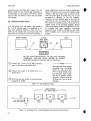
a. Connect the 461 A as shown in Figure 5~2.
and above for the Model 461A.
b. Set the 461A GAIN (DB) switch to 40.
Page 6-15/5·16. On the schematic diagram change the
followlnq capacitor values:
c. Set the 654A frequency to 500 kHz and
minimum OUTPUT AMPLlTUOE.
d. Set the 331 A -to measure RMS VOLTS using
the 1 VOLT METER RANGE. Adjust the 654A
OUTPUT for a 0.5 volt Indication on the 331A
Ref. Deslq.
From
To
CB. Cl0
C21. C27. C32
2.2 pF
22pF
6.8 pF
2.2 pF
Meter.
TEST OSCILLATOR
hp 654A
i
,
00
o@@
e
$
@
CIlIIJ@
AMPLIFIER
hp 461A 500 FEEO- THRU
TERMINATION
hp 1I048C
@
n
-s-
on
Q ATTENUATOR. OPTION
DISTORTION ANALYZER
hp 331A
~ I<,~'I
~©
@
@0(O'
~ o~@
@
40
t~ 1KNOWN ACCURACY)
hp 8491A
Figure 5-2.
3 August 1977
Supplement A for 00461:90006
Page 2
Model 461A/462A
Page 6·3. Table 6·1. Change the following part numbers:
Ref.Oesig.
From
To
C9, Cl0
C21, C27; C32
0180.Q155
0160·0170
0180·1701
0160·0128
CHANGE NO.9 applies to Serial Numbers 0946A06021
and greater for the Model 461A, and Serial Numbers
0947 A01786 and greater for the Model 462A.
Page 6-4. Change the part numbers of L 15, 16 to 91400179 (Coil: 22UHI Otv 2. Add to Misc. Parts -hp- Part
Number 0360·1668 (Term Strip for L15, L161 Otv 1.
CHANGE NO.7 For All Serial Numbers.
Page 1·1, Table 1-1. Change the Frequency Response
Specification to: Frequency Response: ± 1 dB. 1 kHl to
CHANGE NO. 10 Applies to all Serial Numbers.
150 MHz when operating Into a 50 n resistive load.
Page 6·4. Change the part number of the "Insulator For
01" from 0340·0580 to 0340.Q583, Reference Change
No.4.
Page 5·2. Change Paragraph 5-8 as follows:
5·8, 50 kHz Gain Check (461A and
Output Voltage Check (461Al.
b.
462AI;
Set the oscillator to 50 kHz and oscillator
amplitude to read 0 dB on the . 10 dB range of the
ae voltmeter.
Page 5-3. Change Paragraph 5·9{b) and (e) as follows:
b. Set the oscillator frequency to 50 kHz and
adjust its amplitude to read 0 dB on the . 10 dB
range of the ae voltmeter.
e. Record the error at 2 MHz for use in Paragraph 5-12. The reference for high frequency
response must be 50 kHz.
Page 54. Change Paragraph 5-12Ic) and
(f)
as follows:
c. Increase the amplitude of the signal generator to read 0 dB on the 0 dB range of the RF Voltmeter. (Include the variation from the 50 kHz
reference as recorded in Paragraph 5-9, Step e.)
f. Connect as in position B. The ac voltmeter
must read the reference at 50 kHz (0 dB on the
o dB ranqel ± 1 dB or less.
ERRATA
Page 5·8, Paragraph 5·22. Steps d. e and f are printed
twice. Delete the second set on top right column.
Page 5-8. Paragraph 5·23(b). Change Step b to read: Connect the ac voltmeter to position "A" and adjust the output of the oscillator for a reading on the ac voltmeter of
·10 d8 at 50 kHz.
CHANGE NO.8 applies to serial numbers 0946A05836
and greater for the Model 461A, and serial numbers
0947A01786 and greater for the Model 462A,
Page 6·4, Table 6-1. Change the part number for XFl
from 1400·0084 to 2110·0170-Post and 2110·0465Cap. Add the following parts as associated hardware:
2110·0467
1400·0090
2190·0054
Hex Nut
Washer
Washer
orv 1
Otv 1
OW 1
Table of Contents
Models 461A/462A
TABLE OF CONTENTS
Page
Section
I
GENERALINFORMATION
5-3. Test Equipment Required
5-5. Performance Checks
5·8. 500 kHz Gain Check
(461A and 462A); Output
Voltage Check (46IA)
5-9. Low Frequency Response
Check (46IA)
5·10. Distortion Check (461A)
5-11. Noise Check (461A and 462A)
5·12. High Frequency Response
Check (46IA)
5-13. Pulse Response Check (462A)
5·14. Pulse Delay Time
Check (462A)
5·15. Maximum Output Check (462A)
5·16. Pulse Duration Check (462A)
5-17. Overload Recovery
Check (461A and 462A)
5-18. Panel Removal and Replacement
5-20. Calibration Procedure
5-22. Power Supply (461A and 462A)
5·23. Gain Calibration
(461A and 462A)
5-24. Frequency Response
Calibration (461A)
5-25. Preliminary Frequency
Response Alignment
5·26. Pulse Response Calibration
5-27. Etched Circuit Boards
5·31. Troubleshooting Procedure
I-I
I-I. General Information
I-I
14. Accessories Available. . . . . . . . . . . .. I-I
1-6. Instrument Identification
1-2
Section
II
Page
INSTALLATION
2-1.
2-3.
2-5.
2-7.
2-10.
2-12.
2-14.
2-16.
Introduction...................
Initial Inspection. . . . . . . . . . . . . . ..
Power Requirements
Grounding Requirements
Installation
Bench Mounting
Rack Mounting
Repackagingfor Shipment
OPERATINGINSTRUCTIONS
3-1
3-1.
3·3.
3·5.
3-7.
3-9.
3-1
3-1
3·1
3-1
3-2
Introduction
Front and Rear Panel Description
Operating Instructions. . . . . . . . . . . .
Impedance Matching
Cascading Amplifiers
Section
IV
Page
THEORY OF OPERATION
4-1
4-1. General Description
4-4. Amplifier Circuits
4-7. Power Supply
4-1
4·1
4-1
Section
V
2-1
2·1
2-1
2-1
2-1
2-1
2-1
2·1
Page
Section
III
2-1
Page
MAINTENANCE
5-]
5-], Introduction
5-1
Section
VI
REPLACEABLE PARTS
6·1. Introduction
6-3. Ordering Information
6-5. Non-listed Parts
5-1
5-1
5-2
5-3
5-3
54
54
, 54
5·5
5-6
5·6
5-7
5·8
5·8
5-8
5-8
5-8
5·9
5-10
.5-12
5-12
Page
6-]
6-1
6·]
, 6·1
Appendix
A
B
C
CODE LIST OF MANUFACTURES
SALES AND SERVICE OFFICES
MANUAL BACKDATING CHANGES
LIST OF TABLES
Number
I-I. Specifications
5-], Test Equipment Required
ii
Page
,. 1-]/1-2
5-D/5-1/5-2
Number
Page
5-2. Troubleshooting Tips
6-1. Replaceable Parts
5-13
6-2
------
•
-------Table of Contents
Models 461A/462A
LIST OF ILLUSTRATIONS
Nnmber
1·1. Model 461A/462A Wideband
Amplifiers
3·1. Front and Rear Panel
Description .~-;3-2. Operating Instructions
3·3. Cascading 461A or 462A Amplifiers
with InputProtective Circuit
4·1. Simplified-Block Diagram
5·1. Gain Check Setnp
5·2. Distortion Check Setup
5·3. High Freqnency Response
Check
5-4. Pulse Response Check Setup
Page
1·0
3-1
3·2
3-2
.4·1
5·3
5·3
5-4
5·5
Number
Pulse Delay Check Setup
Pulse Duration Check Setup
Panel Removal and Replacement
Preliminary Frequency Response
Calibration Setup
5·9. Input and Output Pulses
of462A
5-1O.BottomView
5.II.TopView
5·12. Schematic Diagram of
Model 461A/462A
6-1. Exploded View of
Al Attenuator
Page
5·5.
5-6.
5-7.
5-8.
5-6
5·6
5·7
5·9
.-.-
5·10
5·11
5·11
5-15/5·16
6·2
ce
iii
Models 461A/462A
Section I
•
\
}
Model 461A
Wide Band Amplifier
•
Model 462A
Wide Band Amplifier
u
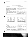
Figure I-I. Hewlett-Packard Model 46lA/462A
Wideband Amplifier
1-0
•
Section I
•
SECTION !
GENERAL INFORMATION
1-1. GENERAL INFORMATION.
J-2. The -hp- Model 461A Wide Band Amplifier is
used primarily where flatness is important. The -hpModel 462A Wide Band Amplifier is used primarily
where rise time is important. The Model 461 }''frequency response is II dB from 1 kHz to 150 Mliz.
The Model 462A rise and fall times are less than .:;.
nanoseconds. Either 40 dB or 20 dB gain can be
selected with the front panel GAIN (DB switch). The
Models 46JA and 462A are shown in Figure J-L The
specifications for both instruments are given in Table
J.l.
1-3. Since the Models 461 A and 462A are nearly
identical, this manual will discuss the instruments in
terms of the Model 46J A. The Model 462A will be
mentioned only when its operation differs from that
of the Model 461 A.
1-4. ACCESSORIES AVAILABLE.
J -5. The .hp- 1l048C 50-ohm feedthrough
termination is an available accessory that is connected
at the output of the Model 461A. The feed through
termination should be used to ensure that the Model
461A is operating into its rated impedance in the
event the instrument is connected to a device with an
impedance greater than 50 ohms.
Table 1-1. Specifications.
•
l
MODEL 462A
MODEL46U
Frequency Range : 1 kHz to 150 MHz.
Frequency Response:
dB. 1 kHz to 150 MHz
when operating into a 50 ohm resistive load (SOC
kHz reference).
Gain at 500 kHz: 40 dB -cl-O.S dB: or 20 dB +;-1.0
dB, selected by front panel switch (inverting).
Pulse Overload Recovery: Less than
times overload.
Pulse Duration
Input Impedance: Nominal 50 ohms.
I
Pulse Response:
Leading Edge and Trailing Edge
Rise Time: Less than 4 nanosecono:
Overshoot: Less than 5Cj(
fOI
J.O% Droop:
~,C
I
us for -101I
'is.
Maximum Input: 1 volt nns or 2. volts pop pulse.":
Equivalent Input Noise Level- Less than 40 uv in
40 dB position when Laded with 50 ohms.
Maximum de InpUT'
)npu , Impedance: Nominal 50 ohms
; volt rms t: :? volts pop pulse."
Maximum Output
resistive ioac.
rated .oac
resistive loao
•
Overload Recover'
times overics c
Lc~~ ::i-!,ii~
-nicroseconc ic:
~:~
i:
Section I
Models 461A/462A
Table I-I. Specifications (Cont'd)
GENERAL
Power Supply: 115 or 230 V +/.10%, 48 to 440 Hz,
5 watts.
Dimensions: 5 1/8 in. (13 em) wide, 3 in. (7,6 em)
high, II in. (27,9 cm) deep.
Weight:
Net: 4lbs (l,8 kg).
Shipping: SIbs (2,3 kg.).
Accessory Furnished: Detachable power cord.
Accessory Available: -hp- 1l048C,
feedthrough termination.
1-6. INSTRUMENT IDENTIFICATION.
1-7. Hewlett-Packard uses a two-section serial
number. The first section (prefix) identifies a
series of instruments. The last section (suffix)
identifies a particular instrument within the series.
If a letter is included with the serial number, it
identifies the country in which the instrument was
1-2
50
ohm
manufactured. If the serial prefix of your instrument differs from the one on the title page of this
manual, a change sheet will be supplied to make
this manual compatable with newer instruments or
the backdating information in Appendix C will
adapt this manual to earlier instruments. All
corresponcence with Hewlett-Packard should include the complete serial number.
•
Models 461A/462A
Section 11
SECTION II
INSTAllATION
2·1. INTRODUCTION.
2·10. INSTALLATION.
2·2, This section contains information and
instructions necessary for the installation and
shipping of the Model 461A Amplifier. Included are
initial inspection procedures, power and grounding
requirements, installation information, and
instructions for repackaging for shipment.
2·11. The Model 46lA is fully transistorized;
therefore, no special cooling is required. However, the
instrument should not be operated where the ambient
temperature exceeds 55° C (131 0 F) or the relative
humidity exceeds 95%.
2·3. INITIAL INSPECTION.
•
24. This instrument was carefully inspected both
mechanically and electrically before shipment. It
should be free of mars and scratches and in perfect
electrical order upon receipt. To confirm this, the
instrument should be inspected for physical damage
in transit. Also check for supplied accessories, and
test the electrical performance of the instrument
using the procedure outlined in Paragraph 5-5. If
there is damage or deficiency, see the warranty on the
inside front cover of this manual.
2·5. POWER REQUIREMENTS.
2·6. The Model 461A can be operated from any
source of 115 or 230 volts (+/·10%), at 4810440
Hertz. With the instrument disconnected from the ac
power source, move the 115/230 V slide switch on
the rear panel until the desired line voltage appears.
Power dissipation is 5 watts maximum.
2·7. GROUNDING REQUIREMENTS.
2-8. To protect operating personnel, the National
Electrical Manufacturers' Association (NEMA)
recommends that the instrument panel and cabinet be
grounded. All Hewlett-Packard instruments are
equipped with a three-conductor power cable which,
when plugged into an appropriate receptacle, grounds
the instrument. The offset pin on the power cable
three-prong connector is the ground wire.
•
2-9. To preserve the protection feature when
operating the instrument from a two-contact outlet,
use a three-prong to two-prong adapter and connect
the green pigtail on the adapter to ground.
2·12. BENCH MOUNTING.
2·13. The Model 46lA is shipped with plastic feet
and tilt stand in place, ready for use as a bench
instrument.
2·14. RACK MOUNTING.
2·15. The Model 461A may be rack mounted by
using an adapter frame (·hp· Part No. 5060.(797).
The adapter frame is a rack frame that accepts any
combination of submodular units. It can be rack
mounted only. For additional information, address
inquiries to your -hp- Sales and Service Office. (See
Appendix B for office locations.)
2·16. REPACKAGING FOR SHIPMENT.
2-]7. The following paragraphs contain a general
guide for repackaging of the isntrument for shipment.
Refer to Paragraph 2-18 if the original container is to
be used; 2-19 if it is not. If you have any questions,
contact your local -hp- Sales and Service Office. (See
Appendix B for office locations.)
----NOTE---If the instrument is to be shipped
to Hewlett-Packard for service or
repair, attach a tag to the
instrument identifying the owner
and indicating the service or repair
to be accomplished; Include the
model number and full serial
number of the instrument. In any
correspondence, identify the
instrument by model number, serial
number, and serial number prefix.
2-1
Section II
Models 461A/462A
2·18. If original container is to be used, proceed as
follows:
a. Wrap instrument in heavy paper or plastic
before placing in an inner container.
a. Place instrument in original container if
available. If it is not available, a suitable
container can be purchased from your
nearest -hp- Sales and Service Office.
b. Place packing material around all sides of
instrument and protect panel face with
cardboard strips.
b. Ensure that container is well sealed with
strong tape or metal bands.
c. Place instrument and inner container in a
heavy carton or wooden box and seal with
strong tape or metal bands.
2-19. If original container is not to be used, proceed
as follows:
d. Mark shipping container with "DELICATE
INSTRUMENT," "FRAGILE" etc.
2-2
•
•
Section 1II
Models 461A/462A
SECTION III
OPERATING INSTRUCTIONS
3·1. INTROOUCTION.
3·5. OPERATING INSTRUCTIONS.
3·2. The Model 461A can be used to faithfully
amplify signals in the I KHz to 150 MHz range. Gai~
settings of 20 dB or 40 dB may be selected with the
front panel GAIN (DB) switch. The Model 461A will
operate within specifications only when its output is
terminated in 50 ohms.
3-6. Figure 3-2 contains the operating instructions
for the Model 461A. Each instruction is keyed to a
drawing of the front panel.
3·3. FRONT ANO REAR PANEL OESCRIPTION.
34. Figure 3·1 describes the function of all the
controls and indicators on both the front and rear
panel.
•
3·7. IMPEOANCE MATCHING.
3-8. Both the input impedance and the output
impedance of the Model 461 A arc 50 ohms. The
Model 461 A out put must be connected to a 50 ohm
load if it is to operate within specifications. If the
input impedance of the load is not 50 ohms, a
terminating impedance of 50 ohms must be
d;;;.,
o,q:J
461A AMPLIFIER
,q:"LETT
PM~A~~,
GAIN !OBI
OFF 20 40
>on
INPUT
~
~
IKC-150MC
o
,,5/<30 fIO<.-"
<E-o<O'\.-
FUS[
'OA
OUTPUT
~
Ie
' " 0,"
·,oln~,·.
e
<50~'
8-
5£Ul TOR
U !ill:] U
0] I
~ U [9
o
-
1\ I
-
a
JJJ
46IA-B-1828A
CD GAIN (DB) switch: Applies primary power and
selects gain.
050
OHM INPUT connector: Connects input
signal to the instrument. DO NOT APPLY
MORE THAN I VAC OR 2 VDC TO INPUT.
CD 50
•
OUTPUT MUST NOT EXCEED ·6 VOLTS DC
OR +0.6 VOLTS DC.
CD AC
POWER connector:
power to the instrument.
Connects primary
CD LINE VOLTAGE: Selects either J 15 volls ac or
230 volts ac primary power.
OHM OUTPUT connector: Connects
amplified output to load. Output must be
terminated in 50 ohm. VOLTAGE LEVEL AT
CD Fuseholder: Contains a 1/4
ampere fast-blow
fuse for both liS and 230 volt operation.
Figure 3·1. Front and Rear Panel Description
3·J
Section III
Models461A/462A
connected across the Model 461A output. The -hpModel II048C· 50 ohm Feedthrough Termination is
recommended for this purpose. The Model II048C
may be easily connected in series with the Model
461A output.
3-9. CASCADING AMPLIFIERS.
3-10. The Model 461A will amplify small signals in
the 5 to 50 millivolt range to an amplitude of 0.5
volts with minimum distortion. Three 651A's or
652A's can be cascaded with a minimum input of 40
microvolts. For protection of the first instrument, a
diode voltage limiter with two diodes in parallel (see
Figure 3-3) can be used. To protect the diodes at high
voltages a 500 ohm resistor must be placed in series
with the input signal. In doing this a ten to one
attenuation is obtained for the first amplifier.
Therefore the first amplifier must be set to 40 dB
gain while the other two should be set to 20 dB gain.
The second two amplifier inputs are protected by the
clipped output of the preceding amplifier. Should
larger output signals be desired, the Model 461A's can
be cascaded with other amplifiers. Concerning
frequencies from 10 MHz to 150 MHz, the -hp- 230A
Power Amplifier can be used in the fourth cascade
position.
hp 461A
WIDE BAND
AMPLIFIER
SIGNAL SOURCE
LOAD
3
2
DO NOT APPLY MORE THAN 1 VAC OR 2 VDC TO INPUT
TERMINALS. VOLTAGE LEVEL APPLIED TO OUTPUT
MUSTNOT EXCEED -6 VOLTS DC OR +0.6 VOLTS DC.
CD Connect
---NOTE---
the 1 KHz to 150 MHz frequency
source to the input of the Model 461A.
CD Connect the
The maximum output voltage
obtainable from the Model
461A is 0.5 volts rms (l Volt
pop for Model 462A). Thus
the maximum input voltage
that can be applied, without
distortion, is 50 mv on the 20
dB range, and 5 mvon the 40
dB range.
output of the Model 461A to a
50·ohm load.
Q) Set Power and Gain Switch to the desired gain
setting (20 or 40 dB).
Figure 3-2. Operating Instructions
AMPLIFIERS
461A/462A
f
~
5000
IW
SILICON DIODES
(FAST SWITCHING)
,
:
\
hp
@ o
~
<!l
II
II
GAIN
+40DB
lie
@
II
GAIN
+20DB
o
<!l
~
II
~ e@
)I
o
\!l
~
II
GAIN
+20DB
Figure 3-3. Cascading 461A or 462A Amplifiers with Input Protective Circuit
3-2
6.
~
•
Section IV
Models 461A/462A
SECTION IV
THEORY OF OPERATION
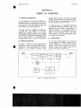
4·1. GENERAL DESCRIPTION.
through A3Q8 constitute a live stage, RC coupled,
cascaded amplifier. Each stage has a gain of 8.4 dB. 2
dB is lost in the input and output emitter followers,
giving the amplifier a total gain of 40 dB.
4-2. The Models 461A and 462A Amplifiers are
essentially identical. In the Model 462A some of the
component values are changed slightly to improve its
pulse response. In this section both instruments will
be presented in terms of the Model 461A.
4-6. Each stage has an an LR feedback circuit with
an adjustable inductor. The feedback circuit in each
stage controls the overall gain of the amplifier at a
different frequency l so the amplifier must be
stagger-tuned, There is some interaction between the
stages at certain frequencies. A3Q9 is the output
emitter follower, and it matches the amplifier output
to a 50 ohm output impedance.
4·3. Figure 4-1 shows a simplified block diagram of
the Model 461A. The amplifier is a five stage,
stagger-tuned, cascaded amplifier with emitter
follower input and output stages. The gain is switched
from 40 dB to 20 dB by attenuating the input by 20
dB. The power supply is a conventional series
regulated supply with +15 volt and -IS volt outputs.
4-7. POWER SUPPl Y.
4·4. AMPLIFIER CIRCUITS.
•
4-8. The power supply generates +15 volts and -IS
volts bias supply to the amplifiers. Breakdown diode
A2CR3 establishes a IS volt reference. Control
transistor A2Q2 detects differences between the
reference voltage and the supply output, and its
output controls the series regulator Ql.
4-5. Figure 5-12 shows the schematic diagram of the
Model 461A. A3Q3 is the input emitter follower,
matching the 50 ohm input impedance to the input
impedance of the amplifier. Transistors A3Q4
IINPUTI
,
,
ATTENUATOR
->
FOLLOWER
AI
~
EMITTER
03
--->
AMPLIFIERS
04-08
--..-.
IOUTPUT I
,
EMITTER
~
FOLLOWER
09
I
~
I
I
PRIMAR)'
I
o,
POWER 8 GAIN
SWITCH
51,53
\
\
\
SERIES
PRIMARY
REGULATED
POWER
POWER SUPPLY
OJ -02-
!
.'_L.",'''"
I
Figure 4-1. Simplified Block Diagram
•
4-1
Models 461 A/462A
Section V
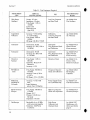
Table 5-1. Test Equipment Required
INSTRUMENT
TYPE
USE
RECOMMENDED
MODEL
Wide Range
Oscillator
Output: 0.5 volts
Impedance: 50 ohms
Freq. Range: I kHz to
10 MHz
Level: 0.5%
Distortion: less
than 0.5%
Low Freq. Response
and Gain Check
-hp- Model 654A
Test Oscillator
Logarithmic
Voltmeter
Accuracy: +/-1% reading
to +/-5% reading
Freq. Range: I kHz to
10 MHz
DB range: -80 dB to +50 dB
Calibration,
Low Freq. Response
and Gain Check
-hp- Model 400EL
AC Voltmeter
Attenuator
Attenuation: 20 dB
Accuracy: 0.1 dB (l kHz to
150 MHz)
Gain Check
Freq. Response Check
and Calibration
-hp- Model 8491A
Attenuation: 40 dB
Accuracy: 0.1 dB (I kHz
to ISO MHz
Gain Check
Freq. Response Check
and Calibration
Distortion
Analyzer
Freq. Range: I kHz to
500 kHz
Sensitivity: Measure 5%
Distortion
Accuracy: +/-3%
Distortion Check
-hp- Model 33 I A,
333A or 334A
Distortion Analyzer
RF Millivolt-
Freq. Range: 500 kHz to
150 MHz
Accuracy: from +/-3% to
+/-5% f.s,
DB Range: -50 to +20 dBm
Frequency Response
Check and Calibration
-hp- Model 340GA
Multimeter
including DC
Voltmeter
Accuracy: +/-1% of full
scale
Input Resistance
greater than 10 Megohm
Power Supply Checks
and Troubleshooting
-hp- Model 412A
Volt-Ohm-Ammeter
Signal Generator
Sweeper
Freq. Range: 100 kHz to
110 MHz
Output: 0.5 V
Flatness: 0.20 dB over
full range
Impedance: 50 ohms
High Freq. Response
Check and Adjustment
-hp- Model 860 I A
Oscilloscope
Bandwidth: de to 50 MHz
with horizontal magnifier
Sensitivity: 0.005V/cm
to 20V/cm
Pulse Droop
Calibra tion and
Overload Check
-hp- Model 180C
Oscilloscope with
1801A and 1820A
plug-ins
Attenuator
meter
5-0
CRITICAL
SPECIFICATIONS
Option 20 with
known accuracy
-hp- Model 8491 A
Opiton 40 with
known accuracy
RF Sampling
Voltmeter
Generator/Sweeper
.).
~;'