1
NSA-03
RTA SUBMITTAL - SPECIFICATIONS
for
NSA/CSS FIRE PUMP REPLACEMENT, BUILDING 9
KUNIA TUNNEL, OAHU, HAWAII
US Army Corps of Engineers
Honolulu District
Submitted by:
Mechanical Enterprises, Inc.
501 Sumner St., Suite 503
Honolulu, Hawaii, 96819
AUGUST 2012
NSA-03
NAS/CSS FIRE PUMP REPLACEMENT, BUILDING 9, KUNIA TUNNEL, OAHU, HI
PROJECT TABLE OF CONTENTS
DIVISION 00 - PROCUREMENT AND CONTRACTING REQUIREMENTS
00 01 00
BID SCHEDULES
DIVISION 01 - GENERAL REQUIREMENTS
SEE MATOC DOCUMENTS
DIVISION 02 - EXISTING CONDITIONS
02 41 00
02 83 13.00 20
DEMOLITION
LEAD IN CONSTRUCTION
DIVISION 03 - CONCRETE
03 30 00
CAST-IN-PLACE CONCRETE
DIVISION 04 - MASONRY
04 20 00
MASONRY
DIVISION 06 - WOOD, PLASTICS, AND COMPOSITES
06 10 00
ROUGH CARPENTRY
DIVISION 07 - THERMAL AND MOISTURE PROTECTION
07
07
07
07
07
07
22
52
60
72
84
92
00
25
00
00
00
00
ROOF AND DECK INSULATION
ELASTOMERIC SHEET ROOFING
FLASHING AND SHEET METAL
ROOF VENTILATORS, GRAVITY-TYPE
FIRESTOPPING
JOINT SEALANTS
DIVISION 08 - OPENINGS
08 11 13
08 71 00
08 91 00
STEEL DOORS AND FRAMES
DOOR HARDWARE
METAL WALL LOUVERS
DIVISION 09 - FINISHES
09 90 00
PAINTS AND COATINGS
DIVISION 10 - SPECIALTIES
10 14 01
EXTERIOR SIGNAGE
DIVISION 13 - SPECIAL CONSTRUCTION
13 48 00.00 10
SEISMIC PROTECTION FOR MECHANICAL EQUIPMENT
DIVISION 21 - FIRE SUPPRESSION
21 13 13.00 10
21 30 00
WET PIPE SPRINKLER SYSTEM, FIRE PROTECTION
FIRE PUMPS
PROJECT TABLE OF CONTENTS Page 1
RJ000081J
NSA-03
NAS/CSS FIRE PUMP REPLACEMENT, BUILDING 9, KUNIA TUNNEL, OAHU, HI
DIVISION 22 - PLUMBING
22 00 00
PLUMBING, GENERAL PURPOSE
DIVISION 26 - ELECTRICAL
26 05 48.00 10
26 20 00
SEISMIC PROTECTION FOR ELECTRICAL EQUIPMENT
INTERIOR DISTRIBUTION SYSTEM
DIVISION 28 - ELECTRONIC SAFETY AND SECURITY
28 31 64.00 10
FIRE DETECTION AND ALARM SYSTEM, ADDRESSABLE
DIVISION 31 - EARTHWORK
31 11 00
31 23 00.00 20
CLEARING AND GRUBBING
EXCAVATION AND FILL
DIVISION 33 - UTILITIES
33 11 00
33 52 10
33 70 02.00 10
WATER DISTRIBUTION
SERVICE PIPING, FUEL SYSTEMS
ELECTRICAL DISTRIBUTION SYSTEM, UNDERGROUND
-- End of Project Table of Contents --
PROJECT TABLE OF CONTENTS Page 2
RJ000081J
NSA-03
NAS/CSS FIRE PUMP REPLACEMENT, BUILDING 9, KUNIA TUNNEL, OAHU, HI
SECTION TABLE OF CONTENTS
DIVISION 00 - PROCUREMENT AND CONTRACTING REQUIREMENTS
DOCUMENT 00 01 00
BID SCHEDULES
PART 1
GENERAL
-- End of Section Table of Contents --
DOCUMENT 00 01 00
Page 1
RJ000081J
NSA-03
FIRE PUMP REPLACEMENT, BUILDING 9. KUNIA , OAHU, HAWAII
RJ0008IJ
BIDDING SCHEDULE
FIRE PUMP REPLACEMENT, BUILDING 9
KUNIA, OAHU, HAWAII
ITEM
NO.
DESCRIPTION
AMOUNT
0001
NEW CONSTRUCTION
The fire pump building, equipment
and site work that is not part of the
existing system..
LS
0002
REPAIR WORK
The fire pumps, associated piping, and
electrical work for the pumps.
LS
TOTAL BID SCHEDULE
$___________
$___________
$___________
NSA-03
FIRE PUMP REPLACEMENT, BUILDING 9. KUNIA , OAHU, HAWAII
RJ0008IJ
MEASUREMENT AND PAYMENTS
Compensation for all work to be performed under this contract will be made under the payment
item(s) listed herein. Prices(s) and payment(s) for the item(s) shall cover all work, complete and
finished in accordance with the specifications, schedules, and drawings, and shall be full
compensation for all work in connection therewith, including quality control and cost
performance-and payment-bond premiums as specified in the CONTRACT CLAUSES. Price(s)
and payment(s) shall constitute full and final compensation for furnishing all materials,
equipment, management, supervision, labor, transportation, fuel, power, water, and all
incidental items necessary to complete the work, except as otherwise specified to be furnished
by the Government. For the purpose of CONTRACT CLAUSE entitled "PROMPT PAYMENT
FOR CONSTRUCTION CONTRACTS", the term "designated billing office" and "designated
payment office" are as follows:
a. Billing Office
U.S. Army Engineer District, Honolulu
Fort Shafter Resident Office, Bldg 230
Fort Shafter, HI, 96858-5440
b. Payment Office
USACE Finance Center
Attn: CEFC-FP
5722 Integrity Drive
Millington, TN 38054-5005
Item numbers mentioned hereinafter correspond to the item numbers in the BID SCHEDULE.
a. Item No. 0001: New Work: The pump house, equipment and site work that is not part of the
existing system, will be paid for at the contract price, complete in place and ready for use,
including earthwork, cast-in-place concrete, concrete masonry unit walls, elastomeric sheet
roofing rigid roof insulation, flashing and sheet metal, steel doors and frames, metal wall
louvers, painting, exterior signage, wet pipe sprinkler system, plumbing, electrical work, fire
detection and alarm system, underground electrical distribution system, water distribution,
testing, final connections, cleanup, and all incidental items necessary to complete the work.
b. Item No. 0002: Repair Work: The fire pumps, associated piping, and electrical work for the
pumps, will be paid for at the contract price, complete in place and ready for use, including
earthwork, fire pumps, associated piping, electrical work for the fire pumps, testing, final
connections, cleanup, and all incidental items necessary to complete the work.
CONTRACT NO.
SUBMITTAL REGISTER
TITLE AND LOCATION
W9128A-12-D-0001
NSA-03
CONTRACTOR
NAS/CSS FIRE PUMP REPLACEMENT, BUILDING 9, KUNIA TUNNEL, OAHU, HI
A
C
T
I
V
I
T
Y
T
R
A
N
S
M
I
T
T
A
L
N
O
(a)
S
P
E
C
N
O
S
E
C
T
ITEM SUBMITTED
P
A
R
A
G#
R
A
P
H
(b)
(c)
(d)
(e)
DESCRIPTION
SD-01 Preconstruction Submittals
Existing Conditions
SD-07 Certificates
Demolition Plan
02 83 13.00 20 SD-01 Preconstruction Submittals
Occupational and Environmental
Assessment Data Report
Lead Compliance Plan
Competent Person
Training Certification
lead waste management plan
written evidence
Medical Examinations
SD-06 Test Reports
sampling results
Occupational and Environmental
Assessment Data Report
SD-07 Certificates
Testing laboratory
Third party consultant
qualifications
Clearance Certification
SD-11 Closeout Submittals
hazardous waste manifest
turn-in documents or weight
tickets
CONTRACTOR:
SCHEDULE DATES
G
O
V
T
C
L
A
S
S
I
F
I
C
A
T
I
O
N
CONTRACTOR
ACTION
O
R
A
C
T
I
O
N
A
/
E
R
E
V
W
R
(f)
SUBMIT
(g)
APPROVAL MATERIAL
NEEDED
NEEDED
BY
BY
(h)
(i)
APPROVING AUTHORITY
A
C
T
I
O
N
DATE FWD
TO APPR
AUTH/
C
O
D
E
DATE
OF
ACTION
(j)
(k)
DATE RCD DATE FWD DATE RCD
FROM
TO OTHER FROM OTH
CONTR REVIEWER REVIEWER
(l)
(m)
(n)
MAILED
TO
CONTR/
C
O
D
E
DATE
OF
ACTION
DATE RCD
FRM APPR
AUTH
REMARKS
(o)
(p)
(q)
(r)
02 41 00
SUBMITTAL FORM,Jan 96
1.8
1.2.1
1.5.2.3
G
1.5.2.2
1.5.1.1
1.5.1.2
1.5.2.8
3.5.2.1
1.5.2.4
G
G
G
G
G
G
1.5.2.3
1.5.2.3
G
G
1.5.1.3
1.5.1.4
G
G
3.5.1.1
G
3.5.2.1
3.5.2.1
G
G
PREVIOUS EDITION IS OBSOLETE
PAGE 1 OF 16 PAGES
CONTRACT NO.
SUBMITTAL REGISTER
TITLE AND LOCATION
W9128A-12-D-0001
NSA-03
CONTRACTOR
NAS/CSS FIRE PUMP REPLACEMENT, BUILDING 9, KUNIA TUNNEL, OAHU, HI
A
C
T
I
V
I
T
Y
T
R
A
N
S
M
I
T
T
A
L
N
O
(a)
S
P
E
C
N
O
S
E
C
T
ITEM SUBMITTED
P
A
R
A
G#
R
A
P
H
(b)
(c)
(d)
(e)
03 30 00
SUBMITTAL FORM,Jan 96
DESCRIPTION
SD-02 Shop Drawings
Fabrication Drawings
Special Construction
Reinforcing steel
SD-03 Product Data
Materials for curing concrete
Joint sealants
Joint filler
Cement
Portland Cement
Ready-Mix Concrete
Vapor retarder
Vapor retarder
Bonding Materials
Floor Finish Materials
Concrete Curing Materials
Reinforcement
Reinforcement Materials
Liquid Chemical Floor Hardener
Latex bonding compound
Wood Forms
SD-05 Design Data
mix design
Calculations
SD-06 Test Reports
Concrete mix design
CONTRACTOR:
SCHEDULE DATES
G
O
V
T
C
L
A
S
S
I
F
I
C
A
T
I
O
N
CONTRACTOR
ACTION
O
R
A
C
T
I
O
N
A
/
E
R
E
V
W
R
(f)
SUBMIT
(g)
APPROVAL MATERIAL
NEEDED
NEEDED
BY
BY
(h)
(i)
APPROVING AUTHORITY
A
C
T
I
O
N
DATE FWD
TO APPR
AUTH/
C
O
D
E
DATE
OF
ACTION
(j)
(k)
DATE RCD DATE FWD DATE RCD
FROM
TO OTHER FROM OTH
CONTR REVIEWER REVIEWER
(l)
(m)
(n)
MAILED
TO
CONTR/
C
O
D
E
DATE
OF
ACTION
DATE RCD
FRM APPR
AUTH
REMARKS
(o)
(p)
(q)
(r)
1.6.2.1
1.6.2.1
1.6.2.2
2.4.7
2.4.10
2.4.9
2.4.1
2.4.1.3
2.3.2
2.4.6
2.4.6
2.6
2.7
2.3.3
2.5
1.6.2.1
2.7.1
2.4.11
2.1.1
2.3.1
1.6.1.1
1.6.4.1
G
PREVIOUS EDITION IS OBSOLETE
PAGE 2 OF 16 PAGES
CONTRACT NO.
SUBMITTAL REGISTER
TITLE AND LOCATION
W9128A-12-D-0001
NSA-03
CONTRACTOR
NAS/CSS FIRE PUMP REPLACEMENT, BUILDING 9, KUNIA TUNNEL, OAHU, HI
A
C
T
I
V
I
T
Y
T
R
A
N
S
M
I
T
T
A
L
N
O
(a)
S
P
E
C
N
O
S
E
C
T
ITEM SUBMITTED
P
A
R
A
G#
R
A
P
H
(b)
(c)
(d)
(e)
03 30 00
04 20 00
SUBMITTAL FORM,Jan 96
DESCRIPTION
Fly ash
Pozzolan
Ground granulated blast-furnace
slag
Aggregates
Compressive strength tests
Slump
SD-07 Certificates
Curing concrete elements
Pumping concrete
Form removal schedule
VOC Content for form release
agents, curing compounds, and
concrete penetrating sealers
Material Safety Data Sheets
SD-08 Manufacturer’s Instructions
Fly ash
Ground granulated blast-furnace
slag
Welding Procedures
Welding Procedures
Steel Bar
Welder Qualifications
SD-02 Shop Drawings
Detail Drawings
SD-03 Product Data
CONTRACTOR:
SCHEDULE DATES
G
O
V
T
C
L
A
S
S
I
F
I
C
A
T
I
O
N
CONTRACTOR
ACTION
O
R
A
C
T
I
O
N
A
/
E
R
E
V
W
R
(f)
SUBMIT
(g)
APPROVAL MATERIAL
NEEDED
NEEDED
BY
BY
(h)
(i)
APPROVING AUTHORITY
A
C
T
I
O
N
DATE FWD
TO APPR
AUTH/
C
O
D
E
DATE
OF
ACTION
(j)
(k)
DATE RCD DATE FWD DATE RCD
FROM
TO OTHER FROM OTH
CONTR REVIEWER REVIEWER
(l)
(m)
(n)
MAILED
TO
CONTR/
C
O
D
E
DATE
OF
ACTION
DATE RCD
FRM APPR
AUTH
REMARKS
(o)
(p)
(q)
(r)
1.6.4.2
1.6.4.2
1.6.4.3
1.6.4.4
3.11.2.3
2.8.4
1.6.3.1
1.6.3.2
1.6.3.3
1.6.3.4
1.6.3.5
1.6.4.2
1.6.4.3
1.9
1.9
2.5.4
1.9
1.4.2
PREVIOUS EDITION IS OBSOLETE
PAGE 3 OF 16 PAGES
CONTRACT NO.
SUBMITTAL REGISTER
TITLE AND LOCATION
W9128A-12-D-0001
NSA-03
CONTRACTOR
NAS/CSS FIRE PUMP REPLACEMENT, BUILDING 9, KUNIA TUNNEL, OAHU, HI
A
C
T
I
V
I
T
Y
T
R
A
N
S
M
I
T
T
A
L
N
O
(a)
S
P
E
C
N
O
S
E
C
T
ITEM SUBMITTED
P
A
R
A
G#
R
A
P
H
(b)
(c)
(d)
(e)
04 20 00
06 10 00
SUBMITTAL FORM,Jan 96
DESCRIPTION
Concrete Masonry Units (CMU)
Cement
SD-04 Samples
Concrete Masonry Units (CMU)
Anchors, Ties, and Bar
Positioners
Joint Reinforcement
SD-05 Design Data
Unit Strength Method
SD-06 Test Reports
Efflorescence Test
Field Testing of Mortar
Field Testing of Grout
Masonry Cement
Masonry Inspector Qualifications
SD-07 Certificates
Concrete Masonry Units (CMU)
Anchors, Ties, and Bar
Positioners
Joint Reinforcement
Masonry Cement
SD-08 Manufacturer’s Instructions
Masonry Cement
SD-06 Test Reports
Preservative-treated
SD-07 Certificates
CONTRACTOR:
SCHEDULE DATES
G
O
V
T
C
L
A
S
S
I
F
I
C
A
T
I
O
N
CONTRACTOR
ACTION
O
R
A
C
T
I
O
N
A
/
E
R
E
V
W
R
(f)
SUBMIT
(g)
APPROVAL MATERIAL
NEEDED
NEEDED
BY
BY
(h)
(i)
APPROVING AUTHORITY
A
C
T
I
O
N
DATE FWD
TO APPR
AUTH/
C
O
D
E
DATE
OF
ACTION
(j)
(k)
DATE RCD DATE FWD DATE RCD
FROM
TO OTHER FROM OTH
CONTR REVIEWER REVIEWER
(l)
(m)
(n)
MAILED
TO
CONTR/
C
O
D
E
DATE
OF
ACTION
DATE RCD
FRM APPR
AUTH
REMARKS
(o)
(p)
(q)
(r)
2.2
2.4.2
2.2
2.6
2.7
1.2.1.1
3.12.3
3.12.1
3.12.2
2.4.2
1.4.1
2.2
2.6
2.7
2.4.2
2.4.2
1.4.2
PREVIOUS EDITION IS OBSOLETE
PAGE 4 OF 16 PAGES
CONTRACT NO.
SUBMITTAL REGISTER
TITLE AND LOCATION
W9128A-12-D-0001
NSA-03
CONTRACTOR
NAS/CSS FIRE PUMP REPLACEMENT, BUILDING 9, KUNIA TUNNEL, OAHU, HI
A
C
T
I
V
I
T
Y
T
R
A
N
S
M
I
T
T
A
L
N
O
(a)
S
P
E
C
N
O
S
E
C
T
ITEM SUBMITTED
P
A
R
A
G#
R
A
P
H
(b)
(c)
(d)
(e)
06 10 00
07 22 00
07 52 25
SUBMITTAL FORM,Jan 96
DESCRIPTION
Certificates of grade
Preservative treatment
SD-02 Shop Drawings
Insulation Types
SD-03 Product Data
Insulation
Insulation Adhesive
SD-06 Test Reports
Flame spread and smoke
developed ratings
SD-07 Certificates
qualifications
SD-08 Manufacturer’s Instructions
Insulation Adhesive
insulation
SD-03 Product Data
Heat Weldable Thermoplastic
Polyolefin (TPO) Membrane
SD-04 Samples
Heat Weldable Thermoplastic
Polyolefin (TPO) Membrane
SD-07 Certificates
Heat Weldable Thermoplastic
Polyolefin (TPO) Membrane
SD-08 Manufacturer’s Instructions
CONTRACTOR:
SCHEDULE DATES
G
O
V
T
C
L
A
S
S
I
F
I
C
A
T
I
O
N
CONTRACTOR
ACTION
O
R
A
C
T
I
O
N
A
/
E
R
E
V
W
R
(f)
SUBMIT
(g)
APPROVAL MATERIAL
NEEDED
NEEDED
BY
BY
(h)
(i)
APPROVING AUTHORITY
A
C
T
I
O
N
DATE FWD
TO APPR
AUTH/
C
O
D
E
DATE
OF
ACTION
(j)
(k)
DATE RCD DATE FWD DATE RCD
FROM
TO OTHER FROM OTH
CONTR REVIEWER REVIEWER
(l)
(m)
(n)
MAILED
TO
CONTR/
C
O
D
E
DATE
OF
ACTION
DATE RCD
FRM APPR
AUTH
REMARKS
(o)
(p)
(q)
(r)
1.8.1
1.7
2.1.1
2.1
3.2.1
1.4.1
1.3
3.2.1
2.1
2.1.1
2.1.1
2.1.1
PREVIOUS EDITION IS OBSOLETE
PAGE 5 OF 16 PAGES
CONTRACT NO.
SUBMITTAL REGISTER
TITLE AND LOCATION
W9128A-12-D-0001
NSA-03
CONTRACTOR
NAS/CSS FIRE PUMP REPLACEMENT, BUILDING 9, KUNIA TUNNEL, OAHU, HI
A
C
T
I
V
I
T
Y
T
R
A
N
S
M
I
T
T
A
L
N
O
(a)
S
P
E
C
N
O
S
E
C
T
ITEM SUBMITTED
P
A
R
A
G#
R
A
P
H
(b)
(c)
(d)
(e)
07 52 25
07 60 00
07 72 00
07 84 00
07 92 00
SUBMITTAL FORM,Jan 96
DESCRIPTION
Heat Weldable Thermoplastic
Polyolefin (TPO) Membrane
SD-11 Closeout Submittals
Warranty
Information Card
SD-02 Shop Drawings
Roof edge flashing
SD-02 Shop Drawings
Roof Ventilators
SD-02 Shop Drawings
Firestopping Materials
SD-04 Samples
Firestopping Materials
SD-07 Certificates
Manufacturer's Technical
Representative
Firestopping Materials
Firestopping Materials
Installer Qualifications
Inspection
SD-03 Product Data
Sealants
Primers
Bond breakers
Backstops
SD-07 Certificates
CONTRACTOR:
SCHEDULE DATES
G
O
V
T
C
L
A
S
S
I
F
I
C
A
T
I
O
N
CONTRACTOR
ACTION
O
R
A
C
T
I
O
N
A
/
E
R
E
V
W
R
(f)
SUBMIT
(g)
APPROVAL MATERIAL
NEEDED
NEEDED
BY
BY
(h)
(i)
APPROVING AUTHORITY
A
C
T
I
O
N
DATE FWD
TO APPR
AUTH/
C
O
D
E
DATE
OF
ACTION
(j)
(k)
DATE RCD DATE FWD DATE RCD
FROM
TO OTHER FROM OTH
CONTR REVIEWER REVIEWER
(l)
(m)
(n)
MAILED
TO
CONTR/
C
O
D
E
DATE
OF
ACTION
DATE RCD
FRM APPR
AUTH
REMARKS
(o)
(p)
(q)
(r)
2.1.1
1.9
3.7
3.1.9
3.1
G
2.1
2.1
G
1.4.2
2.1
2.1
1.4.1
3.3
2.1
2.2
2.3
2.4
PREVIOUS EDITION IS OBSOLETE
PAGE 6 OF 16 PAGES
CONTRACT NO.
SUBMITTAL REGISTER
TITLE AND LOCATION
W9128A-12-D-0001
NSA-03
CONTRACTOR
NAS/CSS FIRE PUMP REPLACEMENT, BUILDING 9, KUNIA TUNNEL, OAHU, HI
A
C
T
I
V
I
T
Y
T
R
A
N
S
M
I
T
T
A
L
N
O
(a)
S
P
E
C
N
O
S
E
C
T
ITEM SUBMITTED
P
A
R
A
G#
R
A
P
H
(b)
(c)
(d)
(e)
07 92 00
08 11 13
08 71 00
08 91 00
SUBMITTAL FORM,Jan 96
DESCRIPTION
Sealant
SD-02 Shop Drawings
Doors
Doors
Frames
Frames
Accessories
Weatherstripping
SD-03 Product Data
Doors
Frames
Accessories
Weatherstripping
SD-02 Shop Drawings
Hardware schedule
SD-03 Product Data
Hardware items
SD-08 Manufacturer’s Instructions
Installation
SD-02 Shop Drawings
Wall louvers
Wall louvers
SD-03 Product Data
Metal Wall Louvers
SD-04 Samples
Wall louvers
CONTRACTOR:
SCHEDULE DATES
G
O
V
T
C
L
A
S
S
I
F
I
C
A
T
I
O
N
CONTRACTOR
ACTION
O
R
A
C
T
I
O
N
A
/
E
R
E
V
W
R
(f)
SUBMIT
(g)
APPROVAL MATERIAL
NEEDED
NEEDED
BY
BY
(h)
(i)
APPROVING AUTHORITY
A
C
T
I
O
N
DATE FWD
TO APPR
AUTH/
C
O
D
E
DATE
OF
ACTION
(j)
(k)
DATE RCD DATE FWD DATE RCD
FROM
TO OTHER FROM OTH
CONTR REVIEWER REVIEWER
(l)
(m)
(n)
MAILED
TO
CONTR/
C
O
D
E
DATE
OF
ACTION
DATE RCD
FRM APPR
AUTH
REMARKS
(o)
(p)
(q)
(r)
3.3.6
2.1
2.1
2.4
2.4
2.2
2.5
2.1
2.4
2.2
2.5
1.3
2.2
3.1
1.4
1.5
2.2
1.4
PREVIOUS EDITION IS OBSOLETE
PAGE 7 OF 16 PAGES
CONTRACT NO.
SUBMITTAL REGISTER
TITLE AND LOCATION
W9128A-12-D-0001
NSA-03
CONTRACTOR
NAS/CSS FIRE PUMP REPLACEMENT, BUILDING 9, KUNIA TUNNEL, OAHU, HI
A
C
T
I
V
I
T
Y
T
R
A
N
S
M
I
T
T
A
L
N
O
(a)
S
P
E
C
N
O
S
E
C
T
ITEM SUBMITTED
P
A
R
A
G#
R
A
P
H
(b)
(c)
(d)
(e)
08 91 00
09 90 00
DESCRIPTION
Wall louvers
SD-03 Product Data
Coating
Manufacturer's Technical Data
Sheets
SD-04 Samples
Color
SD-07 Certificates
Applicator's qualifications
Qualification Testing
SD-08 Manufacturer’s Instructions
Mixing
Manufacturer's Material Safety
Data Sheets
10 14 01
SD-03 Product Data
Installation
13 48 00.00 10 SD-02 Shop Drawings
Coupling and Bracing
Flexible Couplings or Joints
Equipment Requirements
Contractor Designed Bracing
SD-03 Product Data
Coupling and Bracing
Equipment Requirements
Contractor Designed Bracing
SD-07 Certificates
SUBMITTAL FORM,Jan 96
CONTRACTOR:
SCHEDULE DATES
G
O
V
T
C
L
A
S
S
I
F
I
C
A
T
I
O
N
CONTRACTOR
ACTION
O
R
A
C
T
I
O
N
A
/
E
R
E
V
W
R
(f)
SUBMIT
(g)
APPROVAL MATERIAL
NEEDED
NEEDED
BY
BY
(h)
(i)
APPROVING AUTHORITY
A
C
T
I
O
N
DATE FWD
TO APPR
AUTH/
C
O
D
E
DATE
OF
ACTION
(j)
(k)
DATE RCD DATE FWD DATE RCD
FROM
TO OTHER FROM OTH
CONTR REVIEWER REVIEWER
(l)
(m)
(n)
MAILED
TO
CONTR/
C
O
D
E
DATE
OF
ACTION
DATE RCD
FRM APPR
AUTH
REMARKS
(o)
(p)
(q)
(r)
1.5
2.1
2.1
1.10
1.3
1.4.1.2
3.5.2
1.7.2
3.1
3.1
3.3
1.3
1.2.4
G
3.1
1.3
1.2.4
G
G
G
PREVIOUS EDITION IS OBSOLETE
PAGE 8 OF 16 PAGES
CONTRACT NO.
SUBMITTAL REGISTER
TITLE AND LOCATION
W9128A-12-D-0001
NSA-03
CONTRACTOR
NAS/CSS FIRE PUMP REPLACEMENT, BUILDING 9, KUNIA TUNNEL, OAHU, HI
A
C
T
I
V
I
T
Y
T
R
A
N
S
M
I
T
T
A
L
N
O
(a)
S
P
E
C
N
O
S
E
C
T
ITEM SUBMITTED
P
A
R
A
G#
R
A
P
H
(b)
(c)
(d)
(e)
DESCRIPTION
13 48 00.00 10 Flexible Ball Joints
21 13 13.00 10 SD-02 Shop Drawings
Shop Drawings
As-Built Drawings
SD-03 Product Data
Fire Protection Related
Submittals
Materials and Equipment
Spare Parts
Preliminary Tests
Final Acceptance Test
Onsite Training
Fire Protection Specialist
Sprinkler System Installer
Detailed test procedures
SD-05 Design Data
Sway Bracing
Hydraulic Calculations
SD-06 Test Reports
Preliminary Test Report
Final Acceptance Test Report
SD-07 Certificates
Inspection by Fire Protection
Specialist
SD-10 Operation and Maintenance
Data
SUBMITTAL FORM,Jan 96
CONTRACTOR:
SCHEDULE DATES
G
O
V
T
C
L
A
S
S
I
F
I
C
A
T
I
O
N
CONTRACTOR
ACTION
O
R
A
C
T
I
O
N
A
/
E
R
E
V
W
R
(f)
SUBMIT
(g)
APPROVAL MATERIAL
NEEDED
NEEDED
BY
BY
(h)
(i)
APPROVING AUTHORITY
A
C
T
I
O
N
DATE FWD
TO APPR
AUTH/
C
O
D
E
DATE
OF
ACTION
(j)
(k)
DATE RCD DATE FWD DATE RCD
FROM
TO OTHER FROM OTH
CONTR REVIEWER REVIEWER
(l)
(m)
(n)
MAILED
TO
CONTR/
C
O
D
E
DATE
OF
ACTION
DATE RCD
FRM APPR
AUTH
REMARKS
(o)
(p)
(q)
(r)
2.2
1.4.3
3.11
G
1.4.1
2.3
1.6
3.10
3.11
3.12
1.4.1
1.4.2
3.10
G
1.4.3
1.2.1.3
G
G
3.10
3.11
G
G
3.3
G
G
G
G
G
G
PREVIOUS EDITION IS OBSOLETE
PAGE 9 OF 16 PAGES
CONTRACT NO.
SUBMITTAL REGISTER
TITLE AND LOCATION
W9128A-12-D-0001
NSA-03
CONTRACTOR
NAS/CSS FIRE PUMP REPLACEMENT, BUILDING 9, KUNIA TUNNEL, OAHU, HI
A
C
T
I
V
I
T
Y
T
R
A
N
S
M
I
T
T
A
L
N
O
(a)
S
P
E
C
N
O
S
E
C
T
ITEM SUBMITTED
P
A
R
A
G#
R
A
P
H
(b)
(c)
(d)
(e)
DESCRIPTION
21 13 13.00 10 Operating and Maintenance
Manuals
21 30 00
SD-02 Shop Drawings
Installation Drawings
As-Built Drawings
Piping Layout
Pump Room
SD-03 Product Data
Fire Pump Installation Related
Submittals
Catalog Data
Spare Parts
Preliminary Tests
Field Tests
Fire Protection Specialist
Manufacturer's Representative
Field Training
SD-06 Test Reports
Preliminary Tests
Army Final Acceptance Test
SD-07 Certificates
Fire Protection Specialist
Qualifications of Welders
Qualifications of Installer
Preliminary Test Certification
SUBMITTAL FORM,Jan 96
CONTRACTOR:
SCHEDULE DATES
G
O
V
T
C
L
A
S
S
I
F
I
C
A
T
I
O
N
CONTRACTOR
ACTION
O
R
A
C
T
I
O
N
A
/
E
R
E
V
W
R
(f)
SUBMIT
(g)
APPROVAL MATERIAL
NEEDED
NEEDED
BY
BY
(h)
(i)
APPROVING AUTHORITY
A
C
T
I
O
N
DATE FWD
TO APPR
AUTH/
C
O
D
E
DATE
OF
ACTION
(j)
(k)
DATE RCD DATE FWD DATE RCD
FROM
TO OTHER FROM OTH
CONTR REVIEWER REVIEWER
(l)
(m)
(n)
MAILED
TO
CONTR/
C
O
D
E
DATE
OF
ACTION
DATE RCD
FRM APPR
AUTH
REMARKS
(o)
(p)
(q)
(r)
3.12
1.2
3.9.5
1.2
1.2
G
G
G
G
3.2
2.1
1.7
3.9.2
3.9
1.4.1
1.4.5
3.11
G
G
G
G
3.9.2
3.9.3
1.4.1
1.4.2
1.4.3
1.4.4
G
PREVIOUS EDITION IS OBSOLETE
PAGE 10 OF 16 PAGES
CONTRACT NO.
SUBMITTAL REGISTER
TITLE AND LOCATION
W9128A-12-D-0001
NSA-03
CONTRACTOR
NAS/CSS FIRE PUMP REPLACEMENT, BUILDING 9, KUNIA TUNNEL, OAHU, HI
A
C
T
I
V
I
T
Y
T
R
A
N
S
M
I
T
T
A
L
N
O
(a)
S
P
E
C
N
O
S
E
C
T
ITEM SUBMITTED
P
A
R
A
G#
R
A
P
H
(b)
(c)
(d)
(e)
DESCRIPTION
SD-10 Operation and Maintenance
Data
Operating and Maintenance
Instructions
Flow Meter
22 00 00
SD-02 Shop Drawings
Plumbing System
SD-03 Product Data
Welding
Plumbing System
SD-06 Test Reports
Tests, Flushing and Disinfection
SD-07 Certificates
Materials and Equipment
Bolts
SD-10 Operation and Maintenance
Data
Plumbing System
26 05 48.00 10 SD-02 Shop Drawings
Lighting Fixtures in Buildings
Equipment Requirements
SD-03 Product Data
Lighting Fixtures in Buildings
Equipment Requirements
26 20 00
SD-02 Shop Drawings
Panelboards
CONTRACTOR:
SCHEDULE DATES
G
O
V
T
C
L
A
S
S
I
F
I
C
A
T
I
O
N
CONTRACTOR
ACTION
O
R
A
C
T
I
O
N
A
/
E
R
E
V
W
R
(f)
SUBMIT
(g)
APPROVAL MATERIAL
NEEDED
NEEDED
BY
BY
(h)
(i)
APPROVING AUTHORITY
A
C
T
I
O
N
DATE FWD
TO APPR
AUTH/
C
O
D
E
DATE
OF
ACTION
(j)
(k)
DATE RCD DATE FWD DATE RCD
FROM
TO OTHER FROM OTH
CONTR REVIEWER REVIEWER
(l)
(m)
(n)
MAILED
TO
CONTR/
C
O
D
E
DATE
OF
ACTION
DATE RCD
FRM APPR
AUTH
REMARKS
(o)
(p)
(q)
(r)
21 30 00
SUBMITTAL FORM,Jan 96
3.11
2.16
3.2.1
G
1.5.1
3.2.1
3.2
1.3
2.1.1
3.2.1
G
3.1
1.3
3.1
1.3
2.10
G
PREVIOUS EDITION IS OBSOLETE
PAGE 11 OF 16 PAGES
CONTRACT NO.
SUBMITTAL REGISTER
TITLE AND LOCATION
W9128A-12-D-0001
NSA-03
CONTRACTOR
NAS/CSS FIRE PUMP REPLACEMENT, BUILDING 9, KUNIA TUNNEL, OAHU, HI
A
C
T
I
V
I
T
Y
T
R
A
N
S
M
I
T
T
A
L
N
O
(a)
S
P
E
C
N
O
S
E
C
T
ITEM SUBMITTED
P
A
R
A
G#
R
A
P
H
(b)
(c)
(d)
(e)
26 20 00
DESCRIPTION
Marking strips
SD-03 Product Data
Receptacles
Circuit breakers
Switches
Enclosed circuit breakers
Manual motor starters
SD-06 Test Reports
600-volt wiring test
Grounding system test
Ground-fault receptacle test
28 31 64.00 10 SD-02 Shop Drawings
Detail Drawings
SD-03 Product Data
Storage Batteries
Low Battery Voltage
Special Tools and Spare Parts
Testing
Detailed Test Procedures
Tank Water Level Monitoring
System
SD-06 Test Reports
Testing
SD-07 Certificates
Equipment
Qualifications
SUBMITTAL FORM,Jan 96
C
L
A
S
S
I
F
I
C
A
T
I
O
N
G
2.9
2.10.3
2.8
2.11
2.12
G
G
G
G
G
3.5.2
3.5.4
3.5.3
G
G
G
1.4.2
G
2.4
1.2.2
1.7
3.6
3.6.1
2.10
G
G
G
G
G
3.6
G
1.2.6
1.4.1
G
G
CONTRACTOR
ACTION
O
R
A
C
T
I
O
N
A
/
E
R
E
V
W
R
(f)
3.1.6.1
CONTRACTOR:
SCHEDULE DATES
G
O
V
T
SUBMIT
(g)
APPROVAL MATERIAL
NEEDED
NEEDED
BY
BY
(h)
(i)
PREVIOUS EDITION IS OBSOLETE
APPROVING AUTHORITY
A
C
T
I
O
N
DATE FWD
TO APPR
AUTH/
C
O
D
E
DATE
OF
ACTION
(j)
(k)
DATE RCD DATE FWD DATE RCD
FROM
TO OTHER FROM OTH
CONTR REVIEWER REVIEWER
(l)
(m)
(n)
MAILED
TO
CONTR/
C
O
D
E
DATE
OF
ACTION
DATE RCD
FRM APPR
AUTH
REMARKS
(o)
(p)
(q)
(r)
PAGE 12 OF 16 PAGES
CONTRACT NO.
SUBMITTAL REGISTER
TITLE AND LOCATION
W9128A-12-D-0001
NSA-03
CONTRACTOR
NAS/CSS FIRE PUMP REPLACEMENT, BUILDING 9, KUNIA TUNNEL, OAHU, HI
A
C
T
I
V
I
T
Y
T
R
A
N
S
M
I
T
T
A
L
N
O
(a)
S
P
E
C
N
O
S
E
C
T
ITEM SUBMITTED
P
A
R
A
G#
R
A
P
H
(b)
(c)
(d)
(e)
DESCRIPTION
28 31 64.00 10 SD-10 Operation and Maintenance
Data
Operating and Maintenance
Instructions
31 23 00.00 20 SD-01 Preconstruction Submittals
Shoring and Sheeting Plan
Dewatering work plan
SD-06 Test Reports
Fill and backfill
Select material
Density tests
33 11 00
SD-03 Product Data
Piping Materials
Water distribution main
Indicator posts
Valve boxes
SD-06 Test Reports
Disinfection
SD-07 Certificates
Water distribution main
Water service line
Lining
SD-08 Manufacturer’s Instructions
Delivery, storage, and handling
Installation
33 52 10
SD-02 Shop Drawings
SUBMITTAL FORM,Jan 96
CONTRACTOR:
SCHEDULE DATES
G
O
V
T
C
L
A
S
S
I
F
I
C
A
T
I
O
N
CONTRACTOR
ACTION
O
R
A
C
T
I
O
N
A
/
E
R
E
V
W
R
(f)
SUBMIT
(g)
APPROVAL MATERIAL
NEEDED
NEEDED
BY
BY
(h)
(i)
APPROVING AUTHORITY
A
C
T
I
O
N
DATE FWD
TO APPR
AUTH/
C
O
D
E
DATE
OF
ACTION
(j)
(k)
DATE RCD DATE FWD DATE RCD
FROM
TO OTHER FROM OTH
CONTR REVIEWER REVIEWER
(l)
(m)
(n)
MAILED
TO
CONTR/
C
O
D
E
DATE
OF
ACTION
DATE RCD
FRM APPR
AUTH
REMARKS
(o)
(p)
(q)
(r)
3.5
1.6.1
1.6.2
3.10.2.1
3.10.2.2
3.10.2.3
2.1.1
2.1
2.1.2.4
2.1.2.5
2.2.1.1
2.1
2.2
2.1.1.1
1.4
3.1.1
PREVIOUS EDITION IS OBSOLETE
PAGE 13 OF 16 PAGES
CONTRACT NO.
SUBMITTAL REGISTER
TITLE AND LOCATION
W9128A-12-D-0001
NSA-03
CONTRACTOR
NAS/CSS FIRE PUMP REPLACEMENT, BUILDING 9, KUNIA TUNNEL, OAHU, HI
A
C
T
I
V
I
T
Y
T
R
A
N
S
M
I
T
T
A
L
N
O
(a)
S
P
E
C
N
O
S
E
C
T
ITEM SUBMITTED
P
A
R
A
G#
R
A
P
H
(b)
(c)
(d)
(e)
33 52 10
SUBMITTAL FORM,Jan 96
DESCRIPTION
Pipe Hangers and Supports
SD-03 Product Data
Carbon Steel Pipe
Stainless Steel Pipe
Fiberglass Reinforced Plastic
(FRP) Pipe
Exterior Containment Piping
System
Pressure Gauge
Flexible Ball Joint
Bellows Expansion Joint
Swing Type Check Valve
Wafer Type Check Valve
Ball Valve
Plug Valve (PTFE Sleeved
Tapered Type)
Plug Valve (Double Block and
Bleed Type)
Globe Valve
Pressure Relief Valve
Pressure\Vacuum Relief Valve
Foot Valve
Tank Overfill Prevention Valve
FRP Containment Sump
SD-06 Test Reports
Exterior Coating Holiday Test
CONTRACTOR:
SCHEDULE DATES
G
O
V
T
C
L
A
S
S
I
F
I
C
A
T
I
O
N
CONTRACTOR
ACTION
O
R
A
C
T
I
O
N
A
/
E
R
E
V
W
R
(f)
SUBMIT
(g)
APPROVAL MATERIAL
NEEDED
NEEDED
BY
BY
(h)
(i)
APPROVING AUTHORITY
A
C
T
I
O
N
DATE FWD
TO APPR
AUTH/
C
O
D
E
DATE
OF
ACTION
(j)
(k)
DATE RCD DATE FWD DATE RCD
FROM
TO OTHER FROM OTH
CONTR REVIEWER REVIEWER
(l)
(m)
(n)
MAILED
TO
CONTR/
C
O
D
E
DATE
OF
ACTION
DATE RCD
FRM APPR
AUTH
REMARKS
(o)
(p)
(q)
(r)
2.4.9
2.3.1
2.3.2
2.3.3
2.3.4
2.4.8
2.4.11
2.4.12
2.5.1
2.5.2
2.5.3
2.5.5
2.5.6
2.5.4
2.5.7
2.5.8
2.5.9
2.5.10
2.6
3.3.1.1
PREVIOUS EDITION IS OBSOLETE
PAGE 14 OF 16 PAGES
CONTRACT NO.
SUBMITTAL REGISTER
TITLE AND LOCATION
W9128A-12-D-0001
NSA-03
CONTRACTOR
NAS/CSS FIRE PUMP REPLACEMENT, BUILDING 9, KUNIA TUNNEL, OAHU, HI
A
C
T
I
V
I
T
Y
T
R
A
N
S
M
I
T
T
A
L
N
O
(a)
S
P
E
C
N
O
S
E
C
T
ITEM SUBMITTED
P
A
R
A
G#
R
A
P
H
(b)
(c)
(d)
(e)
33 52 10
SUBMITTAL FORM,Jan 96
DESCRIPTION
Preliminary Pneumatic Test
Final Pneumatic Test
Hydrostatic Test
Exterior Containment Piping
Tests
SD-07 Certificates
Contractor Qualifications
Licensed Personnel
Demonstrations
SD-08 Manufacturer’s Instructions
Flexible Ball Joint
Bellows Expansion Joint
SD-10 Operation and Maintenance
Data
Flexible Ball Joint
Bellows Expansion Joint
Swing Type Check Valve
Wafer Type Check Valve
Ball Valve
Plug Valve (PTFE Sleeved
Tapered Type)
Plug Valve (Double Block and
Bleed Type)
Globe Valve
Pressure Relief Valve
Pressure\Vacuum Relief Valve
CONTRACTOR:
SCHEDULE DATES
G
O
V
T
C
L
A
S
S
I
F
I
C
A
T
I
O
N
CONTRACTOR
ACTION
O
R
A
C
T
I
O
N
A
/
E
R
E
V
W
R
(f)
SUBMIT
(g)
APPROVAL MATERIAL
NEEDED
NEEDED
BY
BY
(h)
(i)
APPROVING AUTHORITY
A
C
T
I
O
N
DATE FWD
TO APPR
AUTH/
C
O
D
E
DATE
OF
ACTION
(j)
(k)
DATE RCD DATE FWD DATE RCD
FROM
TO OTHER FROM OTH
CONTR REVIEWER REVIEWER
(l)
(m)
(n)
MAILED
TO
CONTR/
C
O
D
E
DATE
OF
ACTION
DATE RCD
FRM APPR
AUTH
REMARKS
(o)
(p)
(q)
(r)
3.3.1.2
3.3.1.3
3.3.1.4
3.3.1.5
1.4.1
1.4.2.1
3.5
G
2.4.11
2.4.12
2.4.11
2.4.12
2.5.1
2.5.2
2.5.3
2.5.5
2.5.6
2.5.4
2.5.7
2.5.8
PREVIOUS EDITION IS OBSOLETE
PAGE 15 OF 16 PAGES
CONTRACT NO.
SUBMITTAL REGISTER
TITLE AND LOCATION
W9128A-12-D-0001
NSA-03
CONTRACTOR
NAS/CSS FIRE PUMP REPLACEMENT, BUILDING 9, KUNIA TUNNEL, OAHU, HI
A
C
T
I
V
I
T
Y
T
R
A
N
S
M
I
T
T
A
L
N
O
(a)
S
P
E
C
N
O
S
E
C
T
ITEM SUBMITTED
P
A
R
A
G#
R
A
P
H
(b)
(c)
(d)
(e)
33 52 10
DESCRIPTION
Foot Valve
Tank Overfill Prevention Valve
33 70 02.00 10 SD-02 Shop Drawings
As-Built Drawings
SD-03 Product Data
Nameplates
Material and Equipment
Installation Requirements
SD-06 Test Reports
Field Testing
Cable Installation
SD-07 Certificates
Material and Equipment
SUBMITTAL FORM,Jan 96
CONTRACTOR:
SCHEDULE DATES
G
O
V
T
C
L
A
S
S
I
F
I
C
A
T
I
O
N
CONTRACTOR
ACTION
O
R
A
C
T
I
O
N
A
/
E
R
E
V
W
R
(f)
SUBMIT
(g)
APPROVAL MATERIAL
NEEDED
NEEDED
BY
BY
(h)
(i)
APPROVING AUTHORITY
A
C
T
I
O
N
DATE FWD
TO APPR
AUTH/
C
O
D
E
DATE
OF
ACTION
(j)
(k)
DATE RCD DATE FWD DATE RCD
FROM
TO OTHER FROM OTH
CONTR REVIEWER REVIEWER
(l)
(m)
(n)
MAILED
TO
CONTR/
C
O
D
E
DATE
OF
ACTION
DATE RCD
FRM APPR
AUTH
REMARKS
(o)
(p)
(q)
(r)
2.5.9
2.5.10
1.4.1
G
2.2
2.1
3.2
G
G
G
3.7
3.3.1.4
2.1
PREVIOUS EDITION IS OBSOLETE
PAGE 16 OF 16 PAGES
NSA-03
NAS/CSS FIRE PUMP REPLACEMENT, BUILDING 9, KUNIA TUNNEL, OAHU, HI
SECTION TABLE OF CONTENTS
DIVISION 02 - EXISTING CONDITIONS
SECTION 02 41 00
DEMOLITION
PART 1
GENERAL
1.1
REFERENCES
1.2
PROJECT DESCRIPTION
1.2.1
Demolition Plan
1.2.2
General Requirements
1.3
ITEMS TO REMAIN IN PLACE
1.3.1
Existing Construction Limits and Protection
1.3.2
Weather Protection
1.3.3
Utility Service
1.3.4
Facilities
1.4
BURNING
1.5
SUBMITTALS
1.6
QUALITY ASSURANCE
1.6.1
Dust Control
1.7
RELOCATIONS
1.8
EXISTING CONDITIONS
PART 2
PRODUCTS
PART 3
EXECUTION
3.1
EXISTING FACILITIES TO BE REMOVED
3.1.1
Structures
3.1.2
Utilities and Related Equipment
3.1.2.1
General Requirements
3.1.3
Restoration of Turf Areas
3.1.4
Paving and Slabs
3.2
DISPOSITION OF MATERIAL
3.2.1
Title to Materials
3.2.2
Unsalvageable and Non-Recyclable Material
3.3
CLEANUP
-- End of Section Table of Contents --
SECTION 02 41 00
Page 1
RJ000081J
NSA-03
NAS/CSS FIRE PUMP REPLACEMENT, BUILDING 9, KUNIA TUNNEL, OAHU, HI
RJ000081J
SECTION 02 41 00
DEMOLITION
PART 1
1.1
GENERAL
REFERENCES
The publications listed below form a part of this specification to the
extent referenced. The publications are referred to within the text by the
basic designation only.
U.S. ARMY CORPS OF ENGINEERS (USACE)
EM 385-1-1
1.2
1.2.1
(2008; Errata 1-2010; Changes 1-3 2010;
Changes 4-6 2011) Safety and Health
Requirements Manual
PROJECT DESCRIPTION
Demolition Plan
Prepare a Demolition Plan and submit proposed demolition, and removal
procedures for approval before work is started. Include in the plan
procedures for careful removal and disposition of materials specified to be
salvaged, coordination with other work in progress, a disconnection
schedule of utility services, a detailed description of methods and
equipment to be used for each operation and of the sequence of operations.
Identify components and materials to be salvaged for reuse or recycling
with reference to paragraph Existing Facilities to be Removed. Append
tracking forms for all removed materials indicating type, quantities,
condition, destination, and end use. Coordinate with Waste Management
Plan. Provide procedures for safe conduct of the work in accordance with
EM 385-1-1. Plan shall be approved by Contracting Officer prior to work
beginning.
1.2.2
General Requirements
Do not begin demolition until authorization is received from the
Contracting Officer. The work of this section is to be performed in a
manner that maximizes salvage and recycling of materials. Remove rubbish
and debris from the project site; do not allow accumulations inside or
outside the building. In the interest of occupational safety and health,
perform the work in accordance with EM 385-1-1, Section 23, Demolition, and
other applicable Sections.
1.3
ITEMS TO REMAIN IN PLACE
Take necessary precautions to avoid damage to existing items to remain in
place, to be reused, or to remain the property of the Government. Repair
or replace damaged items as approved by the Contracting Officer.
Coordinate the work of this section with all other work indicated.
SECTION 02 41 00
Page 2
NSA-03
NAS/CSS FIRE PUMP REPLACEMENT, BUILDING 9, KUNIA TUNNEL, OAHU, HI
1.3.1
RJ000081J
Existing Construction Limits and Protection
Do not disturb existing construction beyond the extent indicated or
necessary for installation of new construction.
1.3.2
Weather Protection
For portions of the building to remain, protect building interior and
materials and equipment from the weather at all times.
1.3.3
Utility Service
Maintain existing utilities indicated to stay in service and protect
against damage during demolition operations.
1.3.4
Facilities
Protect electrical and mechanical services and utilities. Where removal of
existing utilities and pavement is specified or indicated, provide approved
barricades, temporary covering of exposed areas, and temporary services or
connections for electrical and mechanical utilities.
1.4
BURNING
The use of burning at the project site for the disposal of refuse and
debris will not be permitted.
1.5
SUBMITTALS
Government approval is required for submittals with a "G" designation;
submittals not having a "G" designation are for information only. When
used, a designation following the "G" designation identifies the office
that will review the submittal for the Government. Submit the following in
accordance with Section 01 33 00 SUBMITTAL PROCEDURES:
SD-01 Preconstruction Submittals
Existing Conditions
SD-07 Certificates
Demolition Plan
1.6
1.6.1
QUALITY ASSURANCE
Dust Control
Prevent the spread of dust and avoid the creation of a nuisance in the
surrounding area. Do not use water if it results in hazardous or
objectionable conditions such as, but not limited to, flooding, or
pollution.
1.7
RELOCATIONS
Perform the removal and reinstallation of relocated items as indicated with
workmen skilled in the trades involved. Repair or replace items to be
relocated which are damaged by the Contractor with new undamaged items as
approved by the Contracting Officer.
SECTION 02 41 00
Page 3
NSA-03
NAS/CSS FIRE PUMP REPLACEMENT, BUILDING 9, KUNIA TUNNEL, OAHU, HI
1.8
RJ000081J
EXISTING CONDITIONS
Before beginning any demolition work, survey the site and examine the
drawings and specifications to determine the extent of the work. Record
existing conditions in the presence of the Contracting Officer showing the
condition of structures and other facilities adjacent to areas of
alteration or removal. Photographs sized 4 inch will be acceptable as a
record of existing conditions. Include in the record the elevation of the
top of foundation walls, finish floor elevations, possible conflicting
electrical conduits, plumbing lines, the location and extent of existing
cracks and other damage and description of surface conditions that exist
prior to before starting work. It is the Contractor's responsibility to
verify and document all required outages which will be required during the
course of work, and to note these outages on the record document. Submit
survey results.
PART 2
PRODUCTS
Not used.
PART 3
3.1
EXECUTION
EXISTING FACILITIES TO BE REMOVED
3.1.1
a.
Structures
Remove existing CMU structure indicated completely, including concrete
foundation.
3.1.2
3.1.2.1
Utilities and Related Equipment
General Requirements
Do not interrupt existing utilities serving occupied or used facilities,
except when authorized in writing by the Contracting Officer. Do not
interrupt existing utilities serving facilities occupied and used by the
Government except when approved in writing and then only after temporary
utility services have been approved and provided. Do not begin demolition
work until all utility disconnections have been made. Shut off and cap
utilities for future use, as indicated.
3.1.3
Restoration of Turf Areas
Remove sod from trench excavation, protect sod under shade, water sod
occasionally to prevent drying, and replant sod after completion of utility
work. Provide topsoil and fertilizer to promote growth. Thoroughly
moisten areas to be sodded immediately prior to placing sod. After
completing sodding, blend edges of sodded area smoothly into surrounding
area, Water sod areas on Mondays, Wednesdays and Fridays for one month.
Start watering immediately after completing each day's sodding. Apply
water at a rate sufficient to ensure thorough wetting of the soil to
minimum depth of 4 inches.
3.1.4
Paving and Slabs
Sawcut concrete as indicated. Provide neat sawcuts at limits of pavement
removal as indicated. Pavement and slabs not to be used in this project
shall be removed from the Installation at Contractor's expense.
SECTION 02 41 00
Page 4
NSA-03
NAS/CSS FIRE PUMP REPLACEMENT, BUILDING 9, KUNIA TUNNEL, OAHU, HI
3.2
3.2.1
RJ000081J
DISPOSITION OF MATERIAL
Title to Materials
Except for salvaged items specified in related Sections, and for materials
or equipment scheduled for salvage, all materials and equipment removed and
not reused or salvaged, shall become the property of the Contractor and
shall be removed from Government property. Title to materials resulting
from demolition, and materials and equipment to be removed, is vested in
the Contractor upon approval by the Contracting Officer of the Contractor's
demolition, deconstruction, and removal procedures, and authorization by
the Contracting Officer to begin demolition and deconstruction. The
Government will not be responsible for the condition or loss of, or damage
to, such property after contract award. Showing for sale or selling
materials and equipment on site is prohibited.
3.2.2
Unsalvageable and Non-Recyclable Material
Dispose of unsalvageable and non-recyclable combustible material in the
sanitary fill area located off the site.
3.3
CLEANUP
Remove and transport the debris in a manner that prevents spillage on
streets or adjacent areas. Apply local regulations regarding hauling and
disposal.
-- End of Section --
SECTION 02 41 00
Page 5
NSA-03
NAS/CSS FIRE PUMP REPLACEMENT, BUILDING 9, KUNIA TUNNEL, OAHU, HI
RJ000081J
SECTION TABLE OF CONTENTS
DIVISION 02 - EXISTING CONDITIONS
SECTION 02 83 13.00 20
LEAD IN CONSTRUCTION
PART 1
GENERAL
1.1
REFERENCES
1.2
DEFINITIONS
1.2.1
Action Level
1.2.2
Area Sampling
1.2.3
Competent Person (CP)
1.2.4
Contaminated Room
1.2.5
Decontamination Shower Facility
1.2.6
High Efficiency Particulate Arrestor (HEPA) Filter Equipment
1.2.7
Lead
1.2.8
Lead Control Area
1.2.9
Lead Permissible Exposure Limit (PEL)
1.2.10
Material Containing Lead/Paint with Lead (MCL/PWL)
1.2.11
Personal Sampling
1.2.12
Physical Boundary
1.3
DESCRIPTION
1.3.1
Description of Work
1.3.2
Coordination with Other Work
1.4
SUBMITTALS
1.5
QUALITY ASSURANCE
1.5.1
Qualifications
1.5.1.1
Competent Person (CP)
1.5.1.2
Training Certification
1.5.1.3
Testing Laboratory
1.5.1.4
Third Party Consultant Qualifications
1.5.2
Requirements
1.5.2.1
Competent Person (CP) Responsibilities
1.5.2.2
Lead Compliance Plan
1.5.2.3
Occupational and Environmental Assessment Data Report
1.5.2.4
Medical Examinations
1.5.2.5
Training
1.5.2.6
Respiratory Protection Program
1.5.2.7
Hazard Communication Program
1.5.2.8
Lead Waste Management
1.5.2.9
Environmental, Safety and Health Compliance
1.5.3
Pre-Construction Conference
1.6
EQUIPMENT
1.6.1
Respirators
1.6.2
Special Protective Clothing
1.6.3
Rental Equipment Notification
1.6.4
Vacuum Filters
1.6.5
Equipment for Government Personnel
1.7
PROJECT/SITE CONDITIONS
1.7.1
Protection of Existing Work to Remain
SECTION 02 83 13.00 20
Page 1
NSA-03
NAS/CSS FIRE PUMP REPLACEMENT, BUILDING 9, KUNIA TUNNEL, OAHU, HI
PART 2
PRODUCTS
PART 3
EXECUTION
RJ000081J
3.1
PREPARATION
3.1.1
Protection
3.1.1.1
Notification
3.1.1.2
Lead Control Area
3.1.1.3
Furnishings
3.1.1.4
Heating, Ventilating and Air Conditioning (HVAC) Systems
3.1.1.5
Decontamination Shower Facility
3.1.1.6
Eye Wash Station
3.1.1.7
Mechanical Ventilation System
3.1.1.8
Personnel Protection
3.2
ERECTION
3.2.1
Lead Control Area Requirements
3.3
APPLICATION
3.3.1
Lead Work
3.3.2
Paint with Lead or Material Containing Lead Removal
3.3.2.1
Paint with Lead or Material Containing Lead - Indoor Removal
3.3.2.2
Paint with Lead or Material Containing Lead - Outdoor
Removal
3.3.3
Personnel Exiting Procedures
3.4
FIELD QUALITY CONTROL
3.4.1
Tests
3.4.1.1
Air and Wipe Sampling
3.4.1.2
Sampling After Removal
3.4.1.3
Testing of Material Containing Lead Residue
3.5
CLEANING AND DISPOSAL
3.5.1
Cleanup
3.5.1.1
Clearance Certification
3.5.2
Disposal
3.5.2.1
Disposal Documentation
3.5.2.2
Payment for Hazardous Waste
-- End of Section Table of Contents --
SECTION 02 83 13.00 20
Page 2
NSA-03
NAS/CSS FIRE PUMP REPLACEMENT, BUILDING 9, KUNIA TUNNEL, OAHU, HI
RJ000081J
SECTION 02 83 13.00 20
LEAD IN CONSTRUCTION
PART 1
1.1
GENERAL
REFERENCES
The publications listed below form a part of this specification to the
extent referenced. The publications are referred to within the text by the
basic designation only.
AMERICAN INDUSTRIAL HYGIENE ASSOCIATION (AIHA)
AIHA Z88.6
(2006) Respiratory Protection - Respirator
Use-Physical Qualifications for Personnel
U.S. DEPARTMENT OF HOUSING AND URBAN DEVELOPMENT (HUD)
HUD 6780
(1995; Errata Aug 1996;Rev Ch. 7 - 1997)
Guidelines for the Evaluation and Control
of Lead-Based Paint Hazards in Housing
U.S. NATIONAL ARCHIVES AND RECORDS ADMINISTRATION (NARA)
29 CFR 1926.103
Respiratory Protection
29 CFR 1926.21
Safety Training and Education
29 CFR 1926.33
Access to Employee Exposure and Medical
Records
29 CFR 1926.55
Gases, Vapors, Fumes, Dusts, and Mists
29 CFR 1926.59
Hazard Communication
29 CFR 1926.62
Lead
29 CFR 1926.65
Hazardous Waste Operations and Emergency
Response
40 CFR 260
Hazardous Waste Management System:
40 CFR 261
Identification and Listing of Hazardous
Waste
40 CFR 262
Standards Applicable to Generators of
Hazardous Waste
40 CFR 263
Standards Applicable to Transporters of
Hazardous Waste
40 CFR 264
Standards for Owners and Operators of
Hazardous Waste Treatment, Storage, and
Disposal Facilities
SECTION 02 83 13.00 20
Page 3
General
NSA-03
NAS/CSS FIRE PUMP REPLACEMENT, BUILDING 9, KUNIA TUNNEL, OAHU, HI
RJ000081J
40 CFR 265
Interim Status Standards for Owners and
Operators of Hazardous Waste Treatment,
Storage, and Disposal Facilities
40 CFR 268
Land Disposal Restrictions
49 CFR 172
Hazardous Materials Table, Special
Provisions, Hazardous Materials
Communications, Emergency Response
Information, and Training Requirements
49 CFR 178
Specifications for Packagings
UNDERWRITERS LABORATORIES (UL)
UL 586
1.2
1.2.1
(2009) Standard for High-Efficiency
Particulate, Air Filter Units
DEFINITIONS
Action Level
Employee exposure, without regard to use of respirators, to an airborne
concentration of lead of 30 micrograms per cubic meter of air averaged over
an 8 hour period.
1.2.2
Area Sampling
Sampling of lead concentrations within the lead control area and inside the
physical boundaries which is representative of the airborne lead
concentrations but is not collected in the breathing zone of personnel
(approximately 5 to 6 feet above the floor).
1.2.3
Competent Person (CP)
As used in this section, refers to a person employed by the Contractor who
is trained in the recognition and control of lead hazards in accordance
with current federal, State, and local regulations and has the authority to
take prompt corrective actions to control the lead hazard.
1.2.4
Contaminated Room
Refers to a room for removal of contaminated personal protective equipment
(PPE).
1.2.5
Decontamination Shower Facility
That facility that encompasses a clean clothing storage room, and a
contaminated clothing storage and disposal rooms, with a shower facility in
between.
1.2.6
High Efficiency Particulate Arrestor (HEPA) Filter Equipment
HEPA filtered vacuuming equipment with a UL 586 filter system capable of
collecting and retaining lead-contaminated particulate. A high efficiency
particulate filter demonstrates at least 99.97 percent efficiency against
0.3 micron or larger size particles.
SECTION 02 83 13.00 20
Page 4
NSA-03
NAS/CSS FIRE PUMP REPLACEMENT, BUILDING 9, KUNIA TUNNEL, OAHU, HI
1.2.7
RJ000081J
Lead
Metallic lead, inorganic lead compounds, and organic lead soaps. Excludes
other forms of organic lead compounds.
1.2.8
Lead Control Area
A system of control methods to prevent the spread of lead dust, paint chips
or debris to adjacent areas that may include temporary containment, floor
or ground cover protection, physical boundaries, and warning signs to
prevent unauthorized entry of personnel. HEPA filtered local exhaust
equipment may be used as engineering controls to further reduce personnel
exposures or building/outdoor environmental contamination.
1.2.9
Lead Permissible Exposure Limit (PEL)
Fifty micrograms per cubic meter of air as an 8 hour time weighted average
as determined by 29 CFR 1926.62. If an employee is exposed for more than
eight hours in a work day, the PEL shall be determined by the following
formula:
PEL (micrograms/cubic meter of air) = 400/No. hrs worked per day
1.2.10
Material Containing Lead/Paint with Lead (MCL/PWL)
Any material, including paint, which contains lead as determined by the
testing laboratory using a valid test method. The requirements of this
section does not apply if no detectable levels of lead are found using a
quantitative method for analyzing paint or MCL using laboratory instruments
with specified limits of detection (usually 0.01 percent). An X-Ray
Fluorescence (XRF) instrument is not considered a valid test method.
1.2.11
Personal Sampling
Sampling of airborne lead concentrations within the breathing zone of an
employee to determine the 8 hour time weighted average concentration in
accordance with 29 CFR 1926.62. Samples shall be representative of the
employees' work tasks. Breathing zone shall be considered an area within a
hemisphere, forward of the shoulders, with a radius of 6 to 9 inches and
centered at the nose or mouth of an employee.
1.2.12
Physical Boundary
Area physically roped or partitioned off around lead control area to limit
unauthorized entry of personnel.
1.3
1.3.1
DESCRIPTION
Description of Work
Construction activities impacting PWL or material containing lead which are
covered by this specification include the demolition and/or removal of
material containing lead.
1.3.2
Coordination with Other Work
The contractor shall coordinate with work being performed in adjacent
areas. Coordination procedures shall be explained in the Plan and shall
describe how the Contractor will prevent lead exposure to other contractors
SECTION 02 83 13.00 20
Page 5
NSA-03
NAS/CSS FIRE PUMP REPLACEMENT, BUILDING 9, KUNIA TUNNEL, OAHU, HI
RJ000081J
and/or Government personnel performing work unrelated to lead activities.
1.4
SUBMITTALS
Government approval is required for submittals with a "G" designation;
submittals not having a "G" designation are for Contractor Quality Control
approval. The following shall be submitted in accordance with Section
01 33 00 SUBMITTAL PROCEDURES:
SD-01 Preconstruction Submittals
Occupational and Environmental Assessment Data Report (if
objective data is used to justify excluding the initial
occupational exposure assessment); G
Lead Compliance Plan including CP approval
(signature, date, and certification number); G
Competent Person qualifications; G
Training Certification of workers and supervisors; G
lead waste management plan; G
written evidence that TSD is approved for lead disposal; G
Certification of Medical Examinations; G
SD-06 Test Reports
sampling results; G
Occupational and Environmental Assessment Data Report; G
SD-07 Certificates
Testing laboratory qualifications; G
Third party consultant qualifications; G
Clearance Certification; G
SD-11 Closeout Submittals
Completed and signed hazardous waste manifest from treatment or
disposal facility; G
Waste turn-in documents or weight tickets for non-hazardous wastes
that are disposed of at sanitary or construction and demolition
landfills; G
1.5
QUALITY ASSURANCE
1.5.1
1.5.1.1
Qualifications
Competent Person (CP)
Submit name, address, and telephone number of the CP selected to perform
SECTION 02 83 13.00 20
Page 6
NSA-03
NAS/CSS FIRE PUMP REPLACEMENT, BUILDING 9, KUNIA TUNNEL, OAHU, HI
RJ000081J
responsibilities specified in paragraph entitled "Competent Person (CP)
Responsibilities." Provide documented construction project-related
experience with implementation of OSHA's Lead in Construction standard (
29 CFR 1926.62) which shows ability to assess occupational and
environmental exposure to lead, experience with the use of respirators,
personal protective equipment and other exposure reduction methods to
protect employee health. Submit proper documentation that the CP is
trained and licensed in accordance with federal, State and local laws. .
1.5.1.2
Training Certification
Submit a certificate for each worker and supervisor, signed and dated by
the accredited training provider, stating that the employee has received
the required lead training specified in 29 CFR 1926.62(l)and is certified
to perform or supervise deleading, lead removal or demolition activities
in the state of Hawaii.
1.5.1.3
Testing Laboratory
Submit the name, address, and telephone number of the testing laboratory
selected to perform the air and wipe analysis, testing, and reporting of
airborne concentrations of lead. Use a laboratory participating in the EPA
National Lead Laboratory Accreditation Program (NLLAP) by being accredited
by either the American Association for Laboratory Accreditation (A2LA) or
the American Industrial Hygiene Association (AIHA) and that is successfully
participating in the Environmental Lead Proficiency Analytical Testing
(ELPAT) program to perform sample analysis. Laboratories selected to
perform blood lead analysis shall be OSHA approved.
1.5.1.4
Third Party Consultant Qualifications
Submit the name, address and telephone number of the third party consultant
selected to perform the wipe sampling for determining concentrations of
lead in dust. Submit proper documentation that the consultant is trained
and certified as an inspector technician or inspector/risk assessor by the
USEPA authorized State (or local) certification and accreditation program.
1.5.2
1.5.2.1
Requirements
Competent Person (CP) Responsibilities
a. Verify training meets all federal, State, and local requirements.
b. Review and approve Lead Compliance Plan for conformance to the
applicable referenced standards.
c. Continuously inspect PWL or MCL work for conformance with the approved
plan.
d. Perform (or oversee performance of) air sampling. Recommend upgrades or
downgrades (whichever is appropriate based on exposure) on the use of
PPE (respirators included) and engineering controls.
e. Ensure work is performed in strict accordance with specifications at all
times.
f. Control work to prevent hazardous exposure to human beings and to the
environment at all times.
SECTION 02 83 13.00 20
Page 7
NSA-03
NAS/CSS FIRE PUMP REPLACEMENT, BUILDING 9, KUNIA TUNNEL, OAHU, HI
RJ000081J
g. Supervise final cleaning of the lead control area, review clearance
sample results and make recommendations for further cleaning.
h. Certify the conditions of the work as called for elsewhere in this
specification.
1.5.2.2
Lead Compliance Plan
Submit a detailed job-specific plan of the work procedures to be used in
the disturbance of PWL or MCL. The plan shall include a sketch showing the
location, size, and details of lead control areas, critical barriers,
physical boundaries, location and details of decontamination facilities,
viewing ports, and mechanical ventilation system. Include a description of
equipment and materials, work practices, controls and job responsibilities
for each activity from which lead is emitted. Include in the plan, eating,
drinking, smoking, hygiene facilities and sanitary procedures, interface of
trades, sequencing of lead related work, collected waste water and dust
containing lead and debris, air sampling, respirators, personal protective
equipment, and a detailed description of the method of containment of the
operation to ensure that lead is not released outside of the lead control
area. Include site preparation, cleanup and clearance procedures. Include
occupational and environmental sampling, training and strategy, sampling
and analysis strategy and methodology, frequency of sampling, duration of
sampling, and qualifications of sampling personnel in the air sampling
portion of the plan. Include a description of arrangements made among
contractors on multicontractor worksites to inform affected employees and
to clarify responsibilities to control exposures.
In occupied buildings, the plan shall also include an occupant protection
program that describes the measures that will be taken during the work to
notify and protect the building occupants.
1.5.2.3
Occupational and Environmental Assessment Data Report
If initial monitoring is necessary, submit occupational and environmental
sampling results to the Contracting Officer within three working days of
collection, signed by the testing laboratory employee performing the
analysis, the employee that performed the sampling, and the CP.
In order to reduce the full implementation of 29 CFR 1926.62, the
Contractor shall provide documentation. Submit a report that supports the
determination to reduce full implementation of the requirements of
29 CFR 1926.62 and supporting the Lead Compliance Plan.
a.
The initial monitoring shall represent each job classification, or if
working conditions are similar to previous jobs by the same employer,
provide previously collected exposure data that can be used to estimate
worker exposures per 29 CFR 1926.62. The data shall represent the
worker's regular daily exposure to lead for stated work.
b. Submit worker exposure data gathered during the task based trigger
operations of 29 CFR 1926.62 with a complete process description. This
includes manual demolition, manual scraping, manual sanding, heat gun,
power tool cleaning, rivet busting, cleanup of dry expendable
abrasives, abrasive blast enclosure removal, abrasive blasting,
welding, cutting and torch burning where lead containing coatings are
SECTION 02 83 13.00 20
Page 8
NSA-03
NAS/CSS FIRE PUMP REPLACEMENT, BUILDING 9, KUNIA TUNNEL, OAHU, HI
RJ000081J
present.
c. The initial assessment shall determine the requirement for further
monitoring and the need to fully implement the control and protective
requirements including the lead compliance plan per 29 CFR 1926.62.
1.5.2.4
Medical Examinations
Initial medical surveillance as required by 29 CFR 1926.62 shall be made
available to all employees exposed to lead at any time (1 day) above the
action level. Full medical surveillance shall be made available to all
employees on an annual basis who are or may be exposed to lead in excess of
the action level for more than 30 days a year or as required by 29 CFR
1926.62. Adequate records shall show that employees meet the medical
surveillance requirements of 29 CFR 1926.33, 29 CFR 1926.62 and 29 CFR
1926.103. Provide medical surveillance to all personnel exposed to lead as
indicated in 29 CFR 1926.62. Maintain complete and accurate medical
records of employees for the duration of employment plus 30 years.
1.5.2.5
Training
Train each employee performing work that disturbs lead, who performs
MCL/PWL disposal, and air sampling operations prior to the time of initial
job assignment and annually thereafter, in accordance with 29 CFR 1926.21,
29 CFR 1926.62, and State and local regulations where appropriate.
1.5.2.6
Respiratory Protection Program
a. Provide each employee required to wear a respirator a respirator fit
test at the time of initial fitting and at least annually thereafter as
required by 29 CFR 1926.62.
b. Establish and implement a respiratory protection program as required by
AIHA Z88.6, 29 CFR 1926.103, 29 CFR 1926.62, and 29 CFR 1926.55.
1.5.2.7
Hazard Communication Program
Establish and implement a Hazard Communication Program as required by 29
CFR 1926.59.
1.5.2.8
Lead Waste Management
The Lead Waste Management Plan shall comply with applicable requirements of
federal, State, and local hazardous waste regulations. and address:
a. Identification and classification of wastes associated with the work.
b. Estimated quantities of wastes to be generated and disposed of.
c. Names and qualifications of each contractor that will be transporting,
storing, treating, and disposing of the wastes. Include the facility
location and operator and a 24-hour point of contact. Furnish two
copies of USEPA, State and local hazardous waste permit applications,
permits, manifests, and USEPA Identification numbers.
d. Names and qualifications (experience and training) of personnel who will
be working on-site with hazardous wastes.
SECTION 02 83 13.00 20
Page 9
NSA-03
NAS/CSS FIRE PUMP REPLACEMENT, BUILDING 9, KUNIA TUNNEL, OAHU, HI
RJ000081J
e. List of waste handling equipment to be used in performing the work, to
include cleaning, volume reduction, and transport equipment.
f. Spill prevention, containment, and cleanup contingency measures
including a health and safety plan to be implemented in accordance with
29 CFR 1926.65.
g. Work plan and schedule for waste containment, removal and disposal.
Proper containment of the waste includes using acceptable waste
containers (e.g., 55-gallon drums) as well as proper marking/labeling
of the containers. Wastes shall be cleaned up and containerized daily.
h. Include any process that may alter or treat waste rendering a hazardous
waste non hazardous.
i. Unit cost for hazardous waste disposal according to this plan.
1.5.2.9
Environmental, Safety and Health Compliance
In addition to the detailed requirements of this specification, comply with
laws, ordinances, rules, and regulations of federal, State, and local
authorities regarding lead. Comply with the applicable requirements of the
current issue of 29 CFR 1926.62. Submit matters regarding interpretation of
standards to the Contracting Officer for resolution before starting work.
Where specification requirements and the referenced documents vary, the
most stringent requirement shall apply.
1.5.3
Pre-Construction Conference
Along with the CP, meet with the Contracting Officer to discuss in detail
the Lead Waste Management Plan and the Lead Compliance Plan, including
procedures and precautions for the work.
1.6
1.6.1
EQUIPMENT
Respirators
Furnish appropriate respirators approved by the National Institute for
Occupational Safety and Health (NIOSH), Department of Health and Human
Services, for use in atmospheres containing lead dust, fume and mist.
Respirators shall comply with the requirements of 29 CFR 1926.62.
1.6.2
Special Protective Clothing
Furnish personnel who will be exposed to lead-contaminated dust with proper
disposable protective whole body clothing, head covering, gloves, eye, and
foot coverings as required by 29 CFR 1926.62. Furnish proper disposable
plastic or rubber gloves to protect hands. Reduce the level of protection
only after obtaining approval from the CP.
1.6.3
Rental Equipment Notification
If rental equipment is to be used during PWL or MCL handling and disposal,
SECTION 02 83 13.00 20
Page 10
NSA-03
NAS/CSS FIRE PUMP REPLACEMENT, BUILDING 9, KUNIA TUNNEL, OAHU, HI
RJ000081J
notify the rental agency in writing concerning the intended use of the
equipment.
1.6.4
Vacuum Filters
UL 586 labeled HEPA filters.
1.6.5
Equipment for Government Personnel
Furnish the Contracting Officer with two complete sets of
personal protective equipment (PPE) daily, as required herein, for entry
into and inspection of the lead removal work within the lead controlled
area. Personal protective equipment shall include disposable whole body
covering, including appropriate foot, head, eye, and hand protection. PPE
shall remain the property of the Contractor. The Government will provide
respiratory protection for the Contracting Officer.
1.7
PROJECT/SITE CONDITIONS
1.7.1
Protection of Existing Work to Remain
Perform work without damage or contamination of adjacent areas. Where
existing work is damaged or contaminated, restore work to its original
condition or better as determined by the Contracting Officer.
PART 2
PRODUCTS
Not used.
PART 3
3.1
EXECUTION
PREPARATION
3.1.1
3.1.1.1
Protection
Notification
a. Notify the Contracting Officer 10 days prior to the start of any lead
work.
3.1.1.2
Lead Control Area
a. Physical Boundary - Provide physical boundaries around the lead control
area by roping off the area designated in the work plan or providing
curtains, portable partitions or other enclosures to ensure that lead
will not escape outside of the lead control area.
b. Warning Signs - Provide warning signs at approaches to lead control
areas. Locate signs at such a distance that personnel may read the sign
and take the necessary precautions before entering the area. Signs
shall comply with the requirements of 29 CFR 1926.62.
SECTION 02 83 13.00 20
Page 11
NSA-03
NAS/CSS FIRE PUMP REPLACEMENT, BUILDING 9, KUNIA TUNNEL, OAHU, HI
3.1.1.3
RJ000081J
Furnishings
The Government will remove furniture and equipment from the building before
lead work begins.
3.1.1.4
Heating, Ventilating and Air Conditioning (HVAC) Systems
Shut down, lock out, and isolate HVAC systems that supply, exhaust, or pass
through the lead control areas. Seal intake and exhaust vents in the lead
control area with 6 mil plastic sheet and tape. Seal seams in HVAC
components that pass through the lead control area.
3.1.1.5
Decontamination Shower Facility
Provide clean and contaminated change rooms and shower facilities in
accordance with this specification and 29 CFR 1926.62.
3.1.1.6
Eye Wash Station
Where eyes may be exposed to injurious corrosive materials, suitable
facilities for quick drenching or flushing of the eyes shall be provided
within the work area.
3.1.1.7
Mechanical Ventilation System
a. To the extent feasible, use local exhaust ventilation or other
collection systems, approved by the CP. Local exhaust ventilation
systems shall be evaluated and maintained in accordance with
29 CFR 1926.62.
b. Vent local exhaust outside the building and away from building
ventilation intakes or ensure system is connected to HEPA filters.
c. Use locally exhausted, power actuated tools or manual hand tools.
3.1.1.8
Personnel Protection
Personnel shall wear and use protective clothing and equipment as specified
herein. Eating, smoking, or drinking or application of cosmetics is not
permitted in the lead control area. No one will be permitted in the lead
control area unless they have been appropriately trained and provided with
protective equipment.
3.2
3.2.1
ERECTION
Lead Control Area Requirements
Establish a lead control area by completely establishing barriers and
physical boundaries around the area or structure where PWL or MCL removal
operations will be performed.
SECTION 02 83 13.00 20
Page 12
NSA-03
NAS/CSS FIRE PUMP REPLACEMENT, BUILDING 9, KUNIA TUNNEL, OAHU, HI
3.3
RJ000081J
APPLICATION
3.3.1
Lead Work
Perform lead work in accordance with approved Lead Compliance Plan. Use
procedures and equipment required to limit occupational exposure and
environmental contamination with lead when the work is performed in
accordance with 29 CFR 1926.62 , and as specified herein. Dispose of all
PWL or MCL and associated waste in compliance with federal, State, and
local requirements.
3.3.2
Paint with Lead or Material Containing Lead Removal
Manual or power sanding or grinding of lead surfaces or materials is not
permitted unless tools are equipped with HEPA attachments or wet methods.
The dry sanding or grinding of surfaces that contain lead is prohibited.
Provide methodology for removing lead in the Lead Compliance Plan. Select
lead removal processes to minimize contamination of work areas outside the
control area with lead-contaminated dust or other lead-contaminated debris
or waste and to ensure that unprotected personnel are not exposed to
hazardous concentrations of lead. Describe this removal process in the Lead
Compliance Plan.
3.3.2.1
Paint with Lead or Material Containing Lead - Indoor Removal
Perform manual removal in the lead control areas using enclosures, barriers
or containments . Collect residue debris for disposal in accordance with
federal, State, and local requirements.
3.3.2.2
Paint with Lead or Material Containing Lead - Outdoor Removal
Perform outdoor removal as indicated in federal, State, and local
regulations and in the Lead Compliance Plan. The worksite preparation
(barriers or containments) shall be job dependent and presented in the Lead
Compliance Plan.
3.3.3
Personnel Exiting Procedures
Whenever personnel exit the lead-controlled area, they shall perform the
following procedures and shall not leave the work place wearing any
clothing or equipment worn in the control area:
a. Vacuum all clothing before entering the contaminated change room.
b. Remove protective clothing in the contaminated change room, and place
them in an approved impermeable disposal bag.
c. Wash hands and face at the site
3.4
FIELD QUALITY CONTROL
3.4.1
3.4.1.1
Tests
Air and Wipe Sampling
Conduct sampling for lead in accordance with 29 CFR 1926.62 and as
specified herein. Air and wipe sampling shall be directed or performed by
SECTION 02 83 13.00 20
Page 13
NSA-03
NAS/CSS FIRE PUMP REPLACEMENT, BUILDING 9, KUNIA TUNNEL, OAHU, HI
RJ000081J
the CP.
a. The CP shall be on the job site directing the air and wipe sampling and
inspecting the PWL or MCL removal work to ensure that the requirements
of the contract have been satisfied during the entire PWL or MCL
operation.
b. Collect personal air samples on employees who are anticipated to have
the greatest risk of exposure as determined by the CP. In addition,
collect air samples on at least twenty-five percent of the work crew or
a minimum of two employees, whichever is greater, during each work
shift.
c. Submit results of air samples, signed by the CP, within 72 hours after
the air samples are taken.
d. Conduct area air sampling daily, on each shift in which lead-based paint
removal operations are performed, in areas immediately adjacent to the
lead control area. Sufficient area monitoring shall be conducted to
ensure unprotected personnel are not exposed at or above 30 micrograms
per cubic meter of air. If 30 micrograms per cubic meter of air is
reached or exceeded, stop work, correct the conditions(s) causing the
increased levels. Notify the Contracting Officer immediately. Determine
if condition(s) require any further change in work methods. Removal
work shall resume only after the CP and the Contracting Officer give
approval.
e. Before any work begins, a third party consultant shall collect and
analyze baseline wipe and soil samples in accordance with methods
defined by federal, State, and local standards inside and outside of
the physical boundary to assess the degree of dust contamination in the
facility prior to lead disturbance or removal.
f. Surface Wipe Samples - Collect surface wipe samples on floors at a
location no greater than 10 feet outside the lead control area at a
frequency of once per day while lead removal work is conducted in
occupied buildings. Surface wipe results shall meet criteria in
paragraph "Clearance Certification.
3.4.1.2
Sampling After Removal
After the visual inspection, conduct soil sampling if bare soil is present
during external removal operations and collect wipe and soil samples
according to the HUD protocol contained in HUD 6780 to determine the lead
content of settled dust in micrograms per square meter foot of surface area
and parts per million (ppm) for soil.
3.4.1.3
Testing of Material Containing Lead Residue
Test residue in accordance with 40 CFR 261 for hazardous waste.
3.5
3.5.1
CLEANING AND DISPOSAL
Cleanup
Maintain surfaces of the lead control area free of accumulations of dust
and debris. Restrict the spread of dust and debris; keep waste from being
distributed over the work area. Do not dry sweep or use pressurized air to
clean up the area. At the end of each shift and when the lead operation has
SECTION 02 83 13.00 20
Page 14
NSA-03
NAS/CSS FIRE PUMP REPLACEMENT, BUILDING 9, KUNIA TUNNEL, OAHU, HI
RJ000081J
been completed, clean the controlled area of visible contamination by
vacuuming with a HEPA filtered vacuum cleaner, wet mopping the area and wet
wiping the area as indicated by the Lead Compliance Plan. Reclean areas
showing dust or debris. After visible dust and debris is removed, wet wipe
and HEPA vacuum all surfaces in the controlled area. If adjacent areas
become contaminated at any time during the work, clean, visually inspect,
and then wipe sample all contaminated areas. The CP shall then certify in
writing that the area has been cleaned of lead contamination before
clearance testing.
3.5.1.1
Clearance Certification
The CP shall certify in writing that air samples collected outside the lead
control area during paint removal operations are less than 30 micrograms
per cubic meter of air; the respiratory protection used for the employees
was adequate; the work procedures were performed in accordance with
29 CFR 1926.62; and that there were no visible accumulations of material
and dust containing lead left in the work site. Do not remove the lead
control area or roped off boundary and warning signs prior to the
Contracting Officer's acknowledgement of receipt of the CP certification.
The third party consultant shall certify surface wipe sample results
collected inside and outside the work area are less than 40 micrograms per
square foot on floors, less than 250 micrograms per square foot on interior
window sills and less than 400 micrograms per square foot on window troughs
not significantly greater than the initial surface loading determined prior
to work.
The third party consultant shall certify surface wipe sample results
collected inside and outside the work area are less than 200 micrograms per
square foot on floors or horizontal surfaces.
Certify surface wipe samples are not significantly greater than the initial
surface loading determined prior to work.
Clear the lead control area in industrial facilities of all visible dust
and debris.
For exterior work, soil samples taken at the exterior of the work site
shall be used to determine if soil lead levels had increased at a
statistically significant level (significant at the 95 percent confidence
limit) from the soil lead levels prior to the operation. If soil lead
levels either show a statistically significant increase above soil lead
levels prior to work or soil lead levels above any applicable federal or
state standard for lead in soil, the soil shall be remediated.
3.5.2
Disposal
a. All material, whether hazardous or non-hazardous shall be disposed in
accordance with all laws and provisions and all federal, State or local
regulations. Ensure all waste is properly characterized. The result of
each waste characterization (TCLP for RCRA materials) will dictate
disposal requirements.
b. Contractor is responsible for segregation of waste. Collect
lead-contaminated waste, scrap, debris, bags, containers, equipment,
and lead-contaminated clothing that may produce airborne concentrations
of lead particles. Label the containers in accordance with
29 CFR 1926.62 and 40 CFR 261.
SECTION 02 83 13.00 20
Page 15
NSA-03
NAS/CSS FIRE PUMP REPLACEMENT, BUILDING 9, KUNIA TUNNEL, OAHU, HI
RJ000081J
c. Dispose of hazardous waste at an EPA approved hazardous waste
treatment, storage, or disposal facility off Government property.
d. Store hazardous waste in U.S. Department of Transportation (49 CFR 178)
approved 55 gallon drums. Properly label each drum to identify the type
of waste (49 CFR 172) and the date the drum was filled. For hazardous
waste, the collection drum requires marking/labeling in accordance with
40 CFR 262 during the accumulation/collection timeframe. The
Contracting Officer or an authorized representative will assign an area
for interim storage of waste-containing drums. Do not store hazardous
waste drums in interim storage longer than 90 calendar days from the
date affixed to each drum.
e. Handle, store, transport, and dispose lead or lead-contaminated waste in
accordance with 40 CFR 260, 40 CFR 261, 40 CFR 262, 40 CFR 263,
40 CFR 264, and 40 CFR 265. Comply with land disposal restriction
notification requirements as required by 40 CFR 268.
3.5.2.1
Disposal Documentation
Submit written evidence to demonstrate the hazardous waste treatment,
storage, or disposal facility (TSD) is approved for lead disposal by the
EPA, State or local regulatory agencies. Submit one copy of the completed
hazardous waste manifest, signed and dated by the initial transporter in
accordance with 40 CFR 262. Contractor shall provide a certificate that
the waste was accepted by the disposal facility. Provide turn-in documents
or weight tickets for non-hazardous waste disposal.
3.5.2.2
Payment for Hazardous Waste
Payment for disposal of hazardous and non-hazardous waste will not be made
until a signed copy of the manifest from the treatment or disposal facility
certifying the amount of lead-containing materials or non-hazardous waste
delivered is returned and a copy is furnished to the Government.
-- End of Section --
SECTION 02 83 13.00 20
Page 16
NSA-03
NAS/CSS FIRE PUMP REPLACEMENT, BUILDING 9, KUNIA TUNNEL, OAHU, HI
RJ000081J
SECTION TABLE OF CONTENTS
DIVISION 03 - CONCRETE
SECTION 03 30 00
CAST-IN-PLACE CONCRETE
PART 1
GENERAL
1.1
REFERENCES
1.2
DEFINITIONS
1.3
SUBMITTALS
1.4
MODIFICATION OF REFERENCES
1.5
DELIVERY, STORAGE, AND HANDLING
1.5.1
Reinforcement
1.6
QUALITY ASSURANCE
1.6.1
Design Data
1.6.1.1
Formwork Calculations
1.6.2
Drawings
1.6.2.1
Shop Drawings
1.6.2.2
Reinforcing Steel
1.6.3
Control Submittals
1.6.3.1
Curing Concrete Elements
1.6.3.2
Pumping Concrete
1.6.3.3
Form Removal Schedule
1.6.3.4
VOC Content for form release agents, curing compounds, and
concrete penetrating sealers
1.6.3.5
Material Safety Data Sheets
1.6.4
Test Reports
1.6.4.1
Concrete Mix Design
1.6.4.2
Fly Ash and Pozzolan
1.6.4.3
Ground Granulated Blast-Furnace Slag
1.6.4.4
Aggregates
1.6.5
Special Finisher Qualifications
1.7
ENVIRONMENTAL REQUIREMENTS
1.7.1
Submittals for Environmental Performance
1.8
QUALIFICATIONS FOR CONCRETE TESTING SERVICE
1.9
QUALIFICATIONS FOR WELDING WORK
1.10
CONCRETE SAMPLING AND TESTING
PART 2
PRODUCTS
2.1
MATERIALS FOR FORMS
2.1.1
Wood Forms
2.1.1.1
Concrete Form Plywood (Standard Rough)
2.1.1.2
Overlaid Concrete Form Plywood (Standard Smooth)
2.1.2
Steel Forms
2.2
FORM TIES AND ACCESSORIES
2.3
CONCRETE
2.3.1
Contractor-Furnished Mix Design
2.3.1.1
Mix Proportions for Normal Weight Concrete
2.3.1.2
Required Average Strength of Mix Design
2.3.2
Ready-Mix Concrete
SECTION 03 30 00
Page 1
NSA-03
NAS/CSS FIRE PUMP REPLACEMENT, BUILDING 9, KUNIA TUNNEL, OAHU, HI
2.3.3
Concrete Curing Materials
2.3.3.1
Absorptive Cover
2.3.3.2
Moisture-Retaining Cover
2.3.3.3
Membrane-Forming Curing Compound
2.4
MATERIALS
2.4.1
Cement
2.4.1.1
Fly Ash and Pozzolan
2.4.1.2
Ground Granulated Blast-Furnace Slag
2.4.1.3
Portland Cement
2.4.2
Water
2.4.3
Aggregates
2.4.4
Nonshrink Grout
2.4.5
Admixtures
2.4.5.1
Pozzolan
2.4.6
Vapor Retarder
2.4.7
Materials for Curing Concrete
2.4.7.1
Impervious Sheeting
2.4.7.2
Pervious Sheeting
2.4.7.3
Liquid Membrane-Forming Compound
2.4.8
Liquid Chemical Sealer-Hardener Compound
2.4.9
Expansion/Contraction Joint Filler
2.4.9.1
Preformed Joint Filler Strips
2.4.10
Joint Sealants
2.4.10.1
Horizontal Surfaces, 3 Percent Slope, Maximum
2.4.10.2
Vertical Surfaces Greater Than 3 Percent Slope
2.4.10.3
Joint Sealant Compound
2.4.11
Latex Bonding Compound
2.5
REINFORCEMENT
2.5.1
Reinforcing Bars
2.5.1.1
Weldable Reinforcing Bars
2.5.2
Wire
2.5.2.1
Welded Wire Fabric
2.5.2.2
Steel Wire
2.5.3
Reinforcing Bar Supports
2.5.4
Supports for Reinforcement
2.6
BONDING MATERIALS
2.6.1
Latex Bonding Agent
2.7
FLOOR FINISH MATERIALS
2.7.1
Liquid Chemical Floor Hardener
2.8
CLASSIFICATION AND QUALITY OF CONCRETE
2.8.1
Concrete Classes and Usage
2.8.2
Limits for Concrete Proportions
2.8.3
Maximum Size of Aggregate
2.8.4
Slump
PART 3
EXECUTION
3.1
EXAMINATION
3.2
PREPARATION
3.2.1
General
3.2.2
Subgrade Under Foundations and Footings
3.2.3
Subgrade Under Slabs on Ground
3.2.4
Formwork
3.2.5
Edge Forms and Screed Strips for Slabs
3.2.6
Reinforcement and Other Embedded Items
3.3
FORMS
3.3.1
General
3.3.2
Design and Construction of Formwork
3.3.3
Coating
SECTION 03 30 00
Page 2
RJ000081J
NSA-03
NAS/CSS FIRE PUMP REPLACEMENT, BUILDING 9, KUNIA TUNNEL, OAHU, HI
3.3.4
Reshoring
3.3.5
Reuse
3.3.6
Forms for Standard Rough Form Finish
3.3.7
Forms for Standard Smooth Form Finish
3.3.8
Form Ties
3.3.9
Tolerances for Form Construction
3.3.10
Removal of Forms and Supports
3.3.10.1
Special Requirements for Reduced Time Period
3.4
FORMED SURFACES
3.4.1
Preparation of Form Surfaces
3.4.2
Tolerances
3.4.3
As-Cast Form
3.5
PLACING REINFORCEMENT AND MISCELLANEOUS MATERIALS
3.5.1
General
3.5.2
Vapor Retarder
3.5.3
Reinforcement Supports
3.5.4
Cover
3.5.5
Setting Miscellaneous Material
3.5.6
Construction Joints
3.5.7
Expansion Joints and Contraction Joints
3.5.8
Fabrication
3.5.9
Placing Reinforcement
3.5.10
Spacing of Reinforcing Bars
3.5.11
Concrete Protection for Reinforcement
3.5.12
Welding
3.6
BATCHING, MEASURING, MIXING, AND TRANSPORTING CONCRETE
3.6.1
Measuring
3.6.2
Mixing
3.6.3
Transporting
3.7
PLACING CONCRETE
3.7.1
General Placing Requirements
3.7.2
Footing Placement
3.7.3
Vibration
3.7.4
Application of Latex Bonding Compound
3.7.5
Pumping
3.7.6
Hot Weather
3.7.7
Follow-up
3.7.8
Placing Concrete in Forms
3.7.9
Placing Concrete Slabs
3.7.10
Bonding
3.8
SURFACE FINISHES EXCEPT FLOOR, SLAB, AND PAVEMENT FINISHES
3.8.1
Defects
3.8.2
Not Against Forms (Top of Walls)
3.8.3
Formed Surfaces
3.8.3.1
Tolerances
3.8.3.2
As-Cast Rough Form
3.8.3.3
Standard Smooth Finish
3.9
FLOOR, SLAB, AND MISCELLANEOUS CONSTRUCTION
3.9.1
Finish
3.9.1.1
Scratched
3.9.1.2
Floated
3.9.1.3
Steel Troweled
3.9.1.4
Broomed
3.10
CURING AND PROTECTION
3.10.1
General
3.10.2
Moist Curing
3.10.2.1
Ponding or Immersion
3.10.2.2
Fog Spraying or Sprinkling
3.10.2.3
Pervious Sheeting
SECTION 03 30 00
Page 3
RJ000081J
NSA-03
NAS/CSS FIRE PUMP REPLACEMENT, BUILDING 9, KUNIA TUNNEL, OAHU, HI
RJ000081J
3.10.2.4
Impervious Sheeting
3.10.3
Liquid Membrane-Forming Curing Compound
3.10.3.1
Application
3.10.3.2
Protection of Treated Surfaces
3.10.4
Liquid Chemical Sealer-Hardener
3.10.5
Requirements for Type III, High-Early-Strength Portland Cement
3.10.6
Curing Periods
3.10.7
Curing Methods
3.10.8
Curing Formed Surfaces
3.10.9
Curing Unformed Surfaces
3.10.10
Protection from Mechanical Injury
3.10.11
Protection After Curing
3.11
FIELD QUALITY CONTROL
3.11.1
Sampling
3.11.2
Testing
3.11.2.1
Slump Tests
3.11.2.2
Temperature Tests
3.11.2.3
Compressive Strength Tests
3.11.2.4
Strength of Concrete Structure
3.11.2.5
Testing Concrete Structure for Strength
3.12
JOINTS
3.12.1
Construction Joints
3.12.2
Isolation Joints in Slabs on Ground
3.12.3
Control Joints in Slabs on Ground
3.12.4
Sealing Joints in Slabs on Ground
3.13
INSTALLATION OF ANCHORAGE DEVICES
3.13.1
General
3.13.2
Placing Anchorage Devices
3.14
CONCRETE CONVEYING
3.14.1
Transfer of Concrete At Project Site
3.14.2
Mechanical Equipment for Conveying Concrete
-- End of Section Table of Contents --
SECTION 03 30 00
Page 4
NSA-03
NAS/CSS FIRE PUMP REPLACEMENT, BUILDING 9, KUNIA TUNNEL, OAHU, HI
RJ000081J
SECTION 03 30 00
CAST-IN-PLACE CONCRETE
PART 1
1.1
GENERAL
REFERENCES
The publications listed below form a part of this specification to the
extent referenced. The publications are referred to within the text by the
basic designation only.
AMERICAN ASSOCIATION OF STATE HIGHWAY AND TRANSPORTATION OFFICIALS
(AASHTO)
AASHTO M 182
(2005; R 2009) Standard Specification for
Burlap Cloth Made from Jute or Kenaf and
Cotton Mats
AMERICAN CONCRETE INSTITUTE INTERNATIONAL (ACI)
ACI/MCP-1
(2012) Manual of Concrete Practice Part 1
ACI/MCP-2
(2012) Manual of Concrete Practice Part 2
ACI/MCP-3
(2012) Manual of Concrete Practice Part 3
ACI/MCP-4
(2012) Manual of Concrete Practice Part 4
AMERICAN HARDBOARD ASSOCIATION (AHA)
AHA A135.4
(1995; R 2004) Basic Hardboard
AMERICAN WELDING SOCIETY (AWS)
AWS D1.4/D1.4M
(2011) Structural Welding Code Reinforcing Steel
ASTM INTERNATIONAL (ASTM)
ASTM A185/A185M
(2007) Standard Specification for Steel
Welded Wire Reinforcement, Plain, for
Concrete
ASTM A496/A496M
(2007) Standard Specification for Steel
Wire, Deformed, for Concrete Reinforcement
ASTM A497/A497M
(2007) Standard Specification for Steel
Welded Wire Reinforcement, Deformed, for
Concrete
ASTM A615/A615M
(2009b) Standard Specification for
Deformed and Plain Carbon-Steel Bars for
Concrete Reinforcement
ASTM A706/A706M
(2009b) Standard Specification for
SECTION 03 30 00
Page 5
NSA-03
NAS/CSS FIRE PUMP REPLACEMENT, BUILDING 9, KUNIA TUNNEL, OAHU, HI
RJ000081J
Low-Alloy Steel Deformed and Plain Bars
for Concrete Reinforcement
ASTM A82/A82M
(2007) Standard Specification for Steel
Wire, Plain, for Concrete Reinforcement
ASTM C1107/C1107M
(2011) Standard Specification for Packaged
Dry, Hydraulic-Cement Grout (Nonshrink)
ASTM C1260
(2007) Standard Test Method for Potential
Alkali Reactivity of Aggregates
(Mortar-Bar Method)
ASTM C1293
(2001) Test Method for Concrete Aggregates
by Determination of Length Change of
Concrete Due Alkali-Silica Reaction
ASTM C143/C143M
(2010a) Standard Test Method for Slump of
Hydraulic-Cement Concrete
ASTM C150/C150M
(2011) Standard Specification for Portland
Cement
ASTM C156
(2011) Standard Test Method for Water
Retention by Concrete Curing Materials
ASTM C171
(2007) Standard Specification for Sheet
Materials for Curing Concrete
ASTM C172/C172M
(2010) Standard Practice for Sampling
Freshly Mixed Concrete
ASTM C192/C192M
(2007) Standard Practice for Making and
Curing Concrete Test Specimens in the
Laboratory
ASTM C233/C233M
(2011) Standard Test Method for
Air-Entraining Admixtures for Concrete
ASTM C295/C295M
(2011) Petrographic Examination of
Aggregates for Concrete
ASTM C309
(2011) Standard Specification for Liquid
Membrane-Forming Compounds for Curing
Concrete
ASTM C31/C31M
(2010) Standard Practice for Making and
Curing Concrete Test Specimens in the Field
ASTM C311
(2011b) Sampling and Testing Fly Ash or
Natural Pozzolans for Use as a Mineral
Admixture in Portland-Cement Concrete
ASTM C33/C33M
(2011a) Standard Specification for
Concrete Aggregates
ASTM C39/C39M
(2011) Standard Test Method for
Compressive Strength of Cylindrical
Concrete Specimens
SECTION 03 30 00
Page 6
NSA-03
NAS/CSS FIRE PUMP REPLACEMENT, BUILDING 9, KUNIA TUNNEL, OAHU, HI
RJ000081J
ASTM C42/C42M
(2011) Standard Test Method for Obtaining
and Testing Drilled Cores and Sawed Beams
of Concrete
ASTM C494/C494M
(2011) Standard Specification for Chemical
Admixtures for Concrete
ASTM C595/C595M
(2011) Standard Specification for Blended
Hydraulic Cements
ASTM C618
(2008a) Standard Specification for Coal
Fly Ash and Raw or Calcined Natural
Pozzolan for Use in Concrete
ASTM C920
(2011) Standard Specification for
Elastomeric Joint Sealants
ASTM C94/C94M
(2011b) Standard Specification for
Ready-Mixed Concrete
ASTM C989/C989M
(2011) Standard Specification for Slag
Cement for Use in Concrete and Mortars
ASTM D1557
(2009) Standard Test Methods for
Laboratory Compaction Characteristics of
Soil Using Modified Effort (56,000
ft-lbf/ft3) (2700 kN-m/m3)
ASTM D1751
(2004; R 2008) Standard Specification for
Preformed Expansion Joint Filler for
Concrete Paving and Structural
Construction (Nonextruding and Resilient
Bituminous Types)
ASTM D1752
(2004a; R 2008) Standard Specification for
Preformed Sponge Rubber Cork and Recycled
PVC Expansion
ASTM D5759
(1995; R 2005) Characterization of Coal
Fly Ash and Clean Coal Combustion Fly Ash
for Potential Uses
ASTM D6690
(2007) Standard Specification for Joint
and Crack Sealants, Hot Applied, for
Concrete and Asphalt Pavements
ASTM E1745
(2011) Standard Specification for Water
Vapor Retarders Used in Contact with Soil
or Granular Fill under Concrete Slabs
ASTM E329
(2011c) Standard Specification for
Agencies Engaged in the Testing and/or
Inspection of Materials Used in
Construction
CONCRETE REINFORCING STEEL INSTITUTE (CRSI)
CRSI 10MSP
(2009; 28th Ed) Manual of Standard Practice
SECTION 03 30 00
Page 7
NSA-03
NAS/CSS FIRE PUMP REPLACEMENT, BUILDING 9, KUNIA TUNNEL, OAHU, HI
RJ000081J
NATIONAL INSTITUTE OF STANDARDS AND TECHNOLOGY (NIST)
NIST PS 1
(2009) DOC Voluntary Product Standard PS
1-07, Structural Plywood
U.S. DEPARTMENT OF COMMERCE (DOC)
DOC/NIST PS1
(1995) Construction and Industrial Plywood
with Typical APA Trademarks
U.S. GENERAL SERVICES ADMINISTRATION (GSA)
FS SS-S-200
1.2
(Rev E; Am 1; Notice 1) Sealant, Joint,
Two-Component, Jet-Blast-Resistant,
Cold-Applied, for Portland Cement Concrete
Pavement
DEFINITIONS
a.
"Cementitious material" as used herein must include all portland
cement, pozzolan, fly ash, and ground granulated blast-furnace slag.
b.
"Exposed to public view" means situated so that it can be seen from eye
level from a public location after completion of the building. A
public location is accessible to persons not responsible for operation
or maintenance of the building.
c.
"Chemical admixtures" are materials in the form of powder or fluids
that are added to the concrete to give it certain characteristics not
obtainable with plain concrete mixes.
d.
"Workability (or consistence)" is the ability of a fresh (plastic)
concrete mix to fill the form/mould properly with the desired work
(vibration) and without reducing the concrete's quality. Workability
depends on water content, chemical admixtures, aggregate (shape and
size distribution), cementitious content and age (level of hydration).
1.3
SUBMITTALS
Government approval is required for submittals with a "G" designation;
submittals not having a "G" designation are for information only. When
used, a designation following the "G" designation identifies the office
that will review the submittal for the Government. Submit the following in
accordance with Section 01 33 00 SUBMITTAL PROCEDURES:
SD-02 Shop Drawings
Fabrication Drawings for concrete formwork must be submitted by
the Contractor in accordance with paragraph entitled, "Shop
Drawings," of this section, to include the following:
Special Construction
Reinforcing steel
Reproductions of contract drawings are unacceptable.
Provide erection drawings for concrete that show placement of
SECTION 03 30 00
Page 8
NSA-03
NAS/CSS FIRE PUMP REPLACEMENT, BUILDING 9, KUNIA TUNNEL, OAHU, HI
RJ000081J
reinforcement and accessories, with reference to the contract
drawings.
SD-03 Product Data
Materials for curing concrete
Joint sealants
Submit manufacturer's product data, indicating VOC content.
Manufacturer's catalog data for the following items must include
printed instructions for admixtures, bonding agents, epoxy-resin
adhesive binders, waterstops, and liquid chemical floor hardeners.
Joint filler
Cement
Portland Cement
Ready-Mix Concrete
Vapor retarder
Bonding Materials
Floor Finish Materials
Concrete Curing Materials
Reinforcement
Reinforcement Materials
Liquid Chemical Floor Hardener
Submit documentation indicating percentage of post-industrial
and post-consumer recycled content per unit of product. Indicate
relative dollar value of recycled content products to total dollar
value of products included in project.
Vapor retarder
Latex bonding compound
Wood Forms
SD-05 Design Data
Concrete mix design
Thirty days minimum prior to concrete placement, submit a mix
design for each strength and type of concrete. Submit a complete
list of materials including type; brand; source and amount of
cement, fly ash, pozzolans, ground slag, and admixtures; and
applicable reference specifications. Provide mix proportion data
using at least three different water-cement ratios for each type
of mixture, which produce a range of strength encompassing those
required for each class and type of concrete required. If source
material changes, resubmit mix proportion data using revised
source material. Provide only materials that have been proven by
trial mix studies to meet the requirements of this specification,
unless otherwise approved in writing by the Contracting Officer.
Indicate clearly in the submittal where each mix design is used
when more than one mix design is submitted. Submit additional
data regarding concrete aggregates if the source of aggregate
changes. Submit copies of the fly ash, and pozzolan test results,
in addition. The approval of fly ash, and pozzolan test results
must be within 6 months of submittal date. Obtain acknowledgement
of receipt prior to concrete placement.
SECTION 03 30 00
Page 9
NSA-03
NAS/CSS FIRE PUMP REPLACEMENT, BUILDING 9, KUNIA TUNNEL, OAHU, HI
RJ000081J
Calculations
SD-06 Test Reports
Concrete mix design; G
Fly ash
Pozzolan
Ground granulated blast-furnace slag
Aggregates
Compressive strength tests
Slump
SD-07 Certificates
Curing concrete elements
Pumping concrete
Form removal schedule
VOC Content for form release agents, curing compounds, and
concrete penetrating sealers
Material Safety Data Sheets
SD-08 Manufacturer's Instructions
Fly ash
Ground granulated blast-furnace slag
Welding Procedures must be in accordance with AWS D1.4/D1.4M.
Submit mill certificates for Steel Bar according to the
paragraph entitled, "Fabrication," of this section.
Provide certificates for concrete that are in accordance with
the paragraph entitled, "Classification and Quality of Concrete,"
of this section. Provide certificates that contain project name
and number, date, name of Contractor, name of concrete testing
service, source of concrete aggregates, material manufacturer,
brand name of manufactured materials, material name, values as
specified for each material, and test results. Provide
certificates for Welder Qualifications that are in accordance with
the paragraph entitled, "Qualifications for Welding Work," of this
section.
Welding Procedures
1.4
MODIFICATION OF REFERENCES
Accomplish work in accordance with ACI publications except as modified
SECTION 03 30 00
Page 10
NSA-03
NAS/CSS FIRE PUMP REPLACEMENT, BUILDING 9, KUNIA TUNNEL, OAHU, HI
RJ000081J
herein. Consider the advisory or recommended provisions to be mandatory.
Interpret reference to the "Building Official," the "Structural Engineer,"
and the "Architect/Engineer" to mean the Contracting Officer.
1.5
DELIVERY, STORAGE, AND HANDLING
Do not deliver concrete until vapor retarder, forms, reinforcement,
embedded items, and chamfer strips are in place and ready for concrete
placement. ACI/MCP-2 for job site storage of materials. Protect materials
from contaminants such as grease, oil, and dirt. Ensure materials can be
accurately identified after bundles are broken and tags removed. Do not
store concrete curing compounds or sealers with materials that have a high
capacity to adsorb volatile organic compound (VOC) emissions. Do not store
concrete curing compounds or sealers in occupied spaces.
1.5.1
Reinforcement
Store reinforcement of different sizes and shapes in separate piles or
racks raised above the ground to avoid excessive rusting. Protect from
contaminants such as grease, oil, and dirt. Ensure bar sizes can be
accurately identified after bundles are broken and tags removed.
1.6
QUALITY ASSURANCE
1.6.1
1.6.1.1
Design Data
Formwork Calculations
ACI/MCP-4. Include design calculations indicating arrangement of forms,
sizes and grades of supports (lumber), panels, and related components.
Furnish drawings and calculations of shoring and re-shoring methods
proposed for floor and roof slabs, spandrel beams, and other horizontal
concrete members.
1.6.2
1.6.2.1
Drawings
Shop Drawings
Fabrication Drawings for concrete formwork for Reinforcement Materials,
and for
Special Construction must indicate concrete pressure calculations with both
live and dead loads, along with material types. Provide all design
calculations in accordance with ACI/MCP-2 and ACI/MCP-3.
1.6.2.2
Reinforcing Steel
ACI/MCP-4. Indicate bending diagrams, assembly diagrams, splicing and laps
of bars, shapes, dimensions, and details of bar reinforcing, accessories,
and concrete cover. Do not scale dimensions from structural drawings to
determine lengths of reinforcing bars.
1.6.3
1.6.3.1
Control Submittals
Curing Concrete Elements
Submit proposed materials and methods for curing concrete elements.
SECTION 03 30 00
Page 11
NSA-03
NAS/CSS FIRE PUMP REPLACEMENT, BUILDING 9, KUNIA TUNNEL, OAHU, HI
1.6.3.2
RJ000081J
Pumping Concrete
Submit proposed materials and methods for pumping concrete. Submittal must
include mix designs, pumping equipment including type of pump and size and
material for pipe, and maximum length and height concrete is to be pumped.
1.6.3.3
Form Removal Schedule
Submit schedule for form removal indicating element and minimum length of
time for form removal.
1.6.3.4
VOC Content for form release agents, curing compounds, and concrete
penetrating sealers
Submit certification for the form release agent, curing compounds, and
concrete penetrating sealers that indicate the VOC content of each product.
1.6.3.5
Material Safety Data Sheets
Submit Material Safety Data Sheets (MSDS) for all materials that are
regulated for hazardous health effects. Prominently post the MSDS at the
construction site.
1.6.4
1.6.4.1
Test Reports
Concrete Mix Design
Submit copies of laboratory test reports showing that the mix has been
successfully tested to produce concrete with the properties specified and
that mix must be suitable for the job conditions. Include mill test and
all other test for cement, aggregates, and admixtures in the laboratory
test reports. Provide maximum nominal aggregate size, gradation analysis,
percentage retained and passing sieve, and a graph of percentage retained
verses sieve size. Submit test reports along with the concrete mix
design. Obtain approval before concrete placement.
1.6.4.2
Fly Ash and Pozzolan
Submit test results in accordance with ASTM C618 for fly ash and pozzolan.
Submit test results performed within 6 months of submittal date. Submit
manufacturer's policy statement on fly ash use in concrete.
1.6.4.3
Ground Granulated Blast-Furnace Slag
Submit test results in accordance with ASTM C989/C989M for ground
granulated blast-furnace slag. Submit test results performed within 6
months of submittal date. Submit manufacturer's policy statement on slag
use in concrete.
1.6.4.4
Aggregates
ASTM C1260 for potential alkali-silica reactions, ASTM C295/C295M for
petrographic analysis.
1.6.5
Special Finisher Qualifications
For 35 percent or more fly ash content as a percentage of cementitious
materials, finisher must have a minimum of 3 years' experience finishing
high-volume fly ash concrete.
SECTION 03 30 00
Page 12
NSA-03
NAS/CSS FIRE PUMP REPLACEMENT, BUILDING 9, KUNIA TUNNEL, OAHU, HI
1.7
RJ000081J
ENVIRONMENTAL REQUIREMENTS
Provide space ventilation according to manufacturer recommendations, at a
minimum, during and following installation of concrete curing compound and
sealer. Maintain one of the following ventilation conditions during the
curing compound/sealer curing period or for 72 hours after installation:
a. Supply 100 percent outside air 24 hours a day.
b. Supply airflow at a rate of 6 air changes per hour, when outside
temperatures are between 60 degrees F and 84 degrees F and humidity is
between 30 percent and 60 percent.
c. Supply airflow at a rate of 1.5 air changes per hour, when outside air
conditions are not within the range stipulated above.
1.7.1
Submittals for Environmental Performance
a. Provide data indication the percentage of post-industrial pozzolan (fly
ash, blast furnace slag) cement substitution as a percentage of the
full product composite by weight.
b. Provide data indicating the percentage of post-industrial and
post-consumer recycled content aggregate.
c. Provide product data indicating the percentage of post-consumer recycled
steel content in each type of steel reinforcement as a percentage of
the full product composite by weight.
d. Provide product data stating the location where all products were
manufactured
e. For projects using FSC certified formwork, provide chain-of-custody
documentation for all certified wood products.
f. For projects using reusable formwork, provide data showing how formwork
is reused.
g. Provide MSDS product information data showing that form release agents
meet any environmental performance goals such as using vegetable and
soy based products.
h. Provide MSDS product information data showing that concrete adhesives
meet any environmental performance goals including low emitting, low
volatile organic compound products.
1.8
QUALIFICATIONS FOR CONCRETE TESTING SERVICE
Perform concrete testing by an approved laboratory and inspection service
experienced in sampling and testing concrete. Testing agency must meet the
requirements of ASTM E329.
1.9
QUALIFICATIONS FOR WELDING WORK
Welding procedures must be in accordance with AWS D1.4/D1.4M.
Verify that Welder qualifications are in accordance with AWS D1.4/D1.4M or
under an equivalent qualification test approved in advance. Welders are
SECTION 03 30 00
Page 13
NSA-03
NAS/CSS FIRE PUMP REPLACEMENT, BUILDING 9, KUNIA TUNNEL, OAHU, HI
RJ000081J
permitted to do only the type of welding for which each is specifically
qualified.
1.10
CONCRETE SAMPLING AND TESTING
Testing by the Contractor must include sampling and testing concrete
materials proposed for use in the work and testing the design mix for each
class of concrete. Perform quality control testing during construction.
Sample and test concrete aggregate materials proposed for use in the work
in accordance with ASTM C33/C33M.
Sample and test portland cement in accordance with ASTM C150/C150M.
Sample and test air-entraining admixtures in accordance with ASTM C233/C233M.
Testing must be performed by a Grade I Testing Technician.
PART 2
2.1
PRODUCTS
MATERIALS FOR FORMS
Provide wood, plywood, plastic, carton, or steel.
forms where a smooth form finish is required.
2.1.1
Use plywood or steel
Wood Forms
Use lumber as specified in Section 06 10 00 ROUGH CARPENTRY and as
follows. Provide lumber that is square edged or tongue-and-groove boards,
free of raised grain, knotholes, or other surface defects. Provide plywood
that complies with DOC/NIST PS1, B-B concrete form panels or better or
AHA A135.4, hardboard for smooth form lining.
2.1.1.1
Concrete Form Plywood (Standard Rough)
Provide plywood that conforms to NIST PS 1, B-B, concrete form, not less
than 5/8-inch thick.
2.1.1.2
Overlaid Concrete Form Plywood (Standard Smooth)
Provide plywood that conforms to NIST PS 1, B-B, high density form overlay,
not less than 5/8-inch thick.
2.1.2
Steel Forms
Provide steel form surfaces that do not contain irregularities, dents, or
sags.
2.2
FORM TIES AND ACCESSORIES
The use of wire alone is prohibited. Provide form ties and accessories
that do not reduce the effective cover of the reinforcement.
2.3
2.3.1
CONCRETE
Contractor-Furnished Mix Design
ACI/MCP-1, ACI/MCP-2, ACI/MCP-3 and ACI/MCP-1 except as otherwise
specified. Indicate the compressive strength (f'c) of the concrete for
SECTION 03 30 00
Page 14
NSA-03
NAS/CSS FIRE PUMP REPLACEMENT, BUILDING 9, KUNIA TUNNEL, OAHU, HI
RJ000081J
each portion of the structure(s) and as specified below.
Location
f'c (Min.
ASTM C33/C33M
28-Day Comp.
Maximum Nominal
Strength (psi) Aggregate (Size
No.)
Range of
Maximum
Slump (inches) Water-Cement
Ratio (by
weight)
Footings,
Slab-on-grade
3,000
67
2-3
0.45
Roof Slab
4,000
67
2-3
0.45
Maximum slump shown above may be increased 1 inch for methods of
consolidation other than vibration. Slump may be increased to 8 inches
when superplasticizers are used. The water soluble chloride ion
concentrations in hardened concrete at ages from 28 to 42 days must not
exceed 0.15. Note (a): Entrapped air must be 3 percent or less.
Proportion concrete mixes for strength at 28 days.
2.3.1.1
Mix Proportions for Normal Weight Concrete
Trial design batches, mixture proportioning studies, and testing
requirements for various classes and types of concrete specified are the
responsibility of the Contractor. Base mixture proportions on compressive
strength as determined by test specimens fabricated in accordance with
ASTM C192/C192M and tested in accordance with ASTM C39/C39M. Samples of
all materials used in mixture proportioning studies must be representative
of those proposed for use in the project and must be accompanied by the
manufacturer's or producer's test report indicating compliance with these
specifications. Base trial mixtures having proportions, consistencies, and
suitable for the work on methodology described in ACI/MCP-1. In the trial
mixture, use at least three different water-cement ratios for each type of
mixture, which must produce a range of strength encompassing those required
for each class and type of concrete required on the project. The maximum
water-cement ratio required must be based on equivalent water-cement ratio
calculations as determined by the conversion from the weight ratio of water
to cement plus pozzolan, and ground granulated blast-furnace slag by weight
equivalency method. Design laboratory trial mixture for maximum permitted
slump and air content. Each combination of material proposed for use must
have separate trial mixture, except for accelerator or retarder use can be
provided without separate trial mixture. Report the temperature of
concrete in each trial batch. For each water-cement ratio, at least three
test cylinders for each test age must be made and cured in accordance with
ASTM C192/C192M and tested in accordance with ASTM C39/C39M for 7 and 28
days. From these results, plot a curve showing the relationship between
water-cement ratio and strength for each set of trial mix studies. In
addition, plot a curve showing the relationship between 7 and 28 day
strengths.
2.3.1.2
Required Average Strength of Mix Design
The selected mixture must produce an average compressive strength exceeding
the specified strength by the amount indicated in ACI/MCP-2. When a
concrete production facility has a record of at least 15 consecutive tests,
the standard deviation must be calculated and the required average
compressive strength must be determined in accordance with ACI/MCP-2. When
SECTION 03 30 00
Page 15
NSA-03
NAS/CSS FIRE PUMP REPLACEMENT, BUILDING 9, KUNIA TUNNEL, OAHU, HI
RJ000081J
a concrete production facility does not have a suitable record of tests to
establish a standard deviation, the required average strength must follow
ACI/MCP-2 requirements.
2.3.2
Ready-Mix Concrete
Provide concrete that meets the requirements of ASTM C94/C94M.
Ready-mixed concrete manufacturer must provide duplicate delivery tickets
with each load of concrete delivered. Provide delivery tickets with the
following information in addition to that required by ASTM C94/C94M:
Type and brand cement
Cement content in 94-pound bags per cubic yard of concrete
Maximum size of aggregate
Amount and brand name of admixtures
Total water content expressed by water/cement ratio
2.3.3
Concrete Curing Materials
2.3.3.1
Absorptive Cover
Provide burlap, cotton mats, and other absorbent materials for curing
concrete, as described in ACI 308R.
2.3.3.2
Moisture-Retaining Cover
Provide waterproof paper cover for curing concrete conforming to ASTM C171,
regular or white, or polyethylene sheeting conforming to ASTM C171, or
polyethylene-coated burlap consisting of a laminate of burlap and a white
opaque polyethylene film permanently bonded to the burlap; burlap must
conform to ASTM C171, Class 3, and polyethylene film must conform to
ASTM C171. When tested for water retention in accordance with ASTM C156,
weight of water lost 72 hours after application of moisture retaining
covering material must not exceed 0.039 gram per square centimeter of the
mortar specimen surface.
2.3.3.3
Membrane-Forming Curing Compound
Provide liquid type compound conforming to ASTM C309, Type 1, clear, Type
1D with fugitive dye for interior work and Type 2, white, pigmented for
exterior work.
2.4
2.4.1
MATERIALS
Cement
ASTM C150/C150M, Type I or II or ASTM C595/C595M, Type IP(MS) or IS(MS)
blended cement except as modified herein. Provide blended cement that
consists of a mixture of ASTM C150/C150M, Type II, cement and one of the
following materials: ASTM C618 pozzolan or fly ash, ASTM C989/C989M ground
granulated blast-furnace slag. For portland cement manufactured in a kiln
fueled by hazardous waste, maintain a record of source for each batch.
Supplier must certify that no hazardous waste is used in the fuel mix or
raw materials. Supplier must certify that the hazardous waste is
SECTION 03 30 00
Page 16
NSA-03
NAS/CSS FIRE PUMP REPLACEMENT, BUILDING 9, KUNIA TUNNEL, OAHU, HI
RJ000081J
neutralized by the manufacturing process and that no additional pollutants
are discharged. For exposed concrete, use one manufacturer for each type
of cement, ground slag, fly ash, and pozzolan.
2.4.1.1
Fly Ash and Pozzolan
ASTM C618, Type N, F, or C, except that the maximum allowable loss on
ignition must be 6 percent for Types N and F. Add with cement. Fly ash
content must be a minimum of 15 percent by weight of cementitious material,
provided the fly ash does not reduce the amount of cement in the concrete
mix below the minimum requirements of local building codes. Where the use
of fly ash cannot meet the minimum level, provide the maximum amount of fly
ash permittable that meets the code requirements for cement content.
Report the chemical analysis of the fly ash in accordance with ASTM C311.
Evaluate and classify fly ash in accordance with ASTM D5759.
High contents of supplementary cementitious materials can have some
detrimental effects on the concrete properties, such as slowing excessively
the strength gain rate, and delaying and increasing the difficulty of
finishing. The recommended maximum content (by weight of the total
cementitious material) for these materials are:
1.
For GGBF slag: 50 percent
2. For fly ash or natural pozzolan: 40 percent (25 percent in cold
climates)
2.4.1.2
Ground Granulated Blast-Furnace Slag
ASTM C989/C989M, Grade 80. Slag content must be a minimum of 25 percent by
weight of cementitious material.
2.4.1.3
Portland Cement
Provide cement that conforms to ASTM C150/C150M, Type I, IA, II, or IIA.
Use one brand and type of cement for formed concrete having exposed-to-view
finished surfaces.
2.4.2
Water
Minimize the amount of water in the mix. The amount of water must not
exceed 45 percent by weight of cementitious materials (cement plus
pozzolans), and in general, improve workability by adjusting the grading
rather than by adding water. Water must be fresh, clean, and potable; free
from injurious amounts of oils, acids, alkalis, salts, organic materials,
or other substances deleterious to concrete.
2.4.3
Aggregates
ASR mitigation is not required for this project. The Contractor shall fund
both short term (ASTM C1260) and long term (ASTM C1293) testing required
for this contract. The concrete supplier shall not be responsible to fund
for these tests. No previous test data will be accepted. Test each
aggregate (3C, 3F, pea gravel and sand) used in the concrete mix design.
Include both 14-day and 28-day readings for ASTM C1260 test. For ASTM C1293,
report readings at 28 and 56 days and on a quarterly basis for 1 year.
Provide specific gravity and absorption tests for each aggregate. Provide a
copy of both short term and long term testing to the Honolulu District
SECTION 03 30 00
Page 17
NSA-03
NAS/CSS FIRE PUMP REPLACEMENT, BUILDING 9, KUNIA TUNNEL, OAHU, HI
RJ000081J
Regional Tech Center. All data submitted become the property of the
Government and subject to public dissemination to the Hawaii ASR Working
Group, DOD ASR Working Group, consultants, or other organizations.
2.4.4
Nonshrink Grout
ASTM C1107/C1107M.
2.4.5
Admixtures
ASTM C494/C494M: Type A, water reducing; Type B, retarding; Type C,
accelerating; Type D, water-reducing and retarding; and Type E,
water-reducing and accelerating admixture. Do not use calcium chloride
admixtures.
2.4.5.1
Pozzolan
Provide fly ash or other pozzolans used as admixtures that conform to
ASTM C618.
2.4.6
Vapor Retarder
ASTM E1745, Class A, minimum 15 mils thickness, polyolefin geomembrane.
2.4.7
Materials for Curing Concrete
Use water-based curing compounds, sealers, and coatings with low (maximum
160 grams/liter, less water and less exempt compounds) zero VOC content.
Consider the use of water based or vegetable or soy based curing agents in
lieu of petroleum based products. Consider agents that are not toxic and
emit low or no Volatile Organic Compounds (VOC). Consider the use of
admixtures that offer high performance to increase durability of the finish
product but also have low toxicity and are made from bio-based materials
such as soy, and emit low levels of Volatile Organic Compounds (VOC).
2.4.7.1
Impervious Sheeting
ASTM C171; waterproof paper, clear or white polyethylene sheeting, or
polyethylene-coated burlap.
2.4.7.2
Pervious Sheeting
AASHTO M 182.
2.4.7.3
Liquid Membrane-Forming Compound
ASTM C309, white-pigmented, Type 2, Class B.
2.4.8
Liquid Chemical Sealer-Hardener Compound
Provide surface treatments containing certain chemicals, including sodium
silicate and the fluosilicates of magnesium and zinc. Provide compound that
does not reduce the adhesion of resilient flooring, tile, paint, roofing,
waterproofing, or other material applied to concrete.
2.4.9
Expansion/Contraction Joint Filler
ASTM D1751 or ASTM D1752.
otherwise indicated.
Material must be 1/2 inch thick, unless
SECTION 03 30 00
Page 18
NSA-03
NAS/CSS FIRE PUMP REPLACEMENT, BUILDING 9, KUNIA TUNNEL, OAHU, HI
2.4.9.1
RJ000081J
Preformed Joint Filler Strips
Provide nonextruding and resilient bituminous type filler strips conforming
to ASTM D1751.
2.4.10
Joint Sealants
Use concrete penetrating sealers with a low (maximum 100 grams/liter, less
water and less exempt compounds) VOC content.
2.4.10.1
Horizontal Surfaces, 3 Percent Slope, Maximum
ASTM D6690 or ASTM C920, Type M, Class 25, Use T.
2.4.10.2
Vertical Surfaces Greater Than 3 Percent Slope
ASTM C920, Type M, Grade NS, Class 25, Use T.
2.4.10.3
Joint Sealant Compound
Provide cold-applied, two-component, elastomeric polymer type compound
conforming to FS SS-S-200.
2.4.11
Latex Bonding Compound
ASTM C1059, Type II.
2.5
REINFORCEMENT
Fabrics, connectors, and chairs.
2.5.1
Reinforcing Bars
ACI/MCP-2 unless otherwise specified. Use deformed steel.
with the bars marked A, S, W, Grade 60.
2.5.1.1
ASTM A615/A615M
Weldable Reinforcing Bars
Provide weldable reinforcing bars that conform to ASTM A706/A706M and
ASTM A615/A615M and Supplement S1, Grade 60, except that the maximum carbon
content must be 0.55 percent.
2.5.2
Wire
ASTM A82/A82M or ASTM A496/A496M.
2.5.2.1
Welded Wire Fabric
ASTM A185/A185M or ASTM A497/A497M.
2.5.2.2
Steel Wire
Wire must conform to ASTM A82/A82M.
2.5.3
Reinforcing Bar Supports
Provide bar ties and supports of coated or non corrodible material.
SECTION 03 30 00
Page 19
NSA-03
NAS/CSS FIRE PUMP REPLACEMENT, BUILDING 9, KUNIA TUNNEL, OAHU, HI
2.5.4
RJ000081J
Supports for Reinforcement
Supports include bolsters, chairs, spacers, and other devices necessary for
proper spacing, supporting, and fastening reinforcing bars and wire fabric
in place.
Provide wire bar type supports conforming to ACI/MCP-3, ACI/MCP-4 and
CRSI 10MSP.
Legs of supports in contact with formwork must be hot-dip galvanized, or
plastic coated after fabrication, or stainless-steel bar supports.
2.6
BONDING MATERIALS
2.6.1
Latex Bonding Agent
Latex bonding compound conforming to ASTM C1059/C1059M, Type II.
2.7
FLOOR FINISH MATERIALS
2.7.1
Liquid Chemical Floor Hardener
Hardener must be a colorless aqueous solution containing a blend of
magnesium fluorosilicate and zinc fluorosilicate combined with a wetting
agent. Solution must contain not less than 1/2 pounds of fluorosilicates
per gallon. An approved proprietary chemical hardener may be used provided
hardener is delivered ready for use in manufacturer's original containers,
with low VOC content.
2.8
CLASSIFICATION AND QUALITY OF CONCRETE
2.8.1
Concrete Classes and Usage
Provide concrete classes, compressive strength and usage as follows:
CONCRETE
CLASS
3N
MIN. 28-DAY
COMPRESSIVE
STRENGTH
POUNDS PER
SQ. IN.
3000
REQUIREMENT FOR
AIR ENTRAINMENT
USAGE
Nonair-entrained
For foundation concrete work not
exposed to freezing and thawing or
subjected to hydraulic pressure, such
as footings, pile caps, foundation
mats. For interior slabs on ground to
be covered with resilient flooring
SECTION 03 30 00
Page 20
NSA-03
NAS/CSS FIRE PUMP REPLACEMENT, BUILDING 9, KUNIA TUNNEL, OAHU, HI
CONCRETE
CLASS
MIN. 28-DAY
COMPRESSIVE
STRENGTH
POUNDS PER
SQ. IN.
REQUIREMENT FOR
AIR ENTRAINMENT
USAGE
RJ000081J
4N
4000
Nonair-entrained
For structural concrete work not
exposed to freezing and thawing such
as interior columns, beams, supported
slabs and other structural members for
interior slabs on ground subjected to
foot traffic
2.5N
2500
Nonair-entrained
For concrete not reinforced and not
exposed to freezing and thawing
2.8.2
Limits for Concrete Proportions
Provide limits for maximum water/cement ratio and minimum cement content
for each concrete class as follows:
CONCRETE
CLASS
MAX. WATER/CEMENT
RATIO BY WEIGHT
MIN. CEMENT FOR 3- TO 4-INCH SLUMP,
(NO. OF 94-POUND SACKS) PER CU. YD.
2.5N
0.50
4.75
3N
0.45
5.25
4N
0.45
6.0
* Weight of water to weight of cement in pounds in one cubic yard
of concrete.
2.8.3
Maximum Size of Aggregate
Size of aggregate, designated by the sieve size on which maximum amount of
retained coarse aggregate is 5 to 10 percent by weight, must be as follows:
MAXIMUM SIZE OF AGGREGATE
ASTM C33/C33M SIZE NUMBER
SECTION 03 30 00
TYPE OF CONSTRUCTION
Page 21
NSA-03
NAS/CSS FIRE PUMP REPLACEMENT, BUILDING 9, KUNIA TUNNEL, OAHU, HI
RJ000081J
2 inches
357
Nonreinforced footings
and other flat work
having a depth of not
less than 6 inches, and
nonreinforced walls and
other formed sections
having a dimension
between forms of not less
than 10 inches
1-1/2 inches
467
Monolithic slabs on
ground, concrete fill,
and other flatwork having
a depth of not less than
5 inches and a clear
distance between
reinforcing bars of not
less than 2 inches
3/4 inch
67
Reinforced walls,
columns, girders, beams,
and other formed sections
having a dimension
between forms of not less
than 6 inches and clear
distance between
reinforcing bars or
reinforcing bar and face
of form of not less than
1 inch
3/4 inch
67
Monolithic concrete slabs
and other flatwork having
a depth of not less than
2-1/2 inches and a clear
distance between
reinforcing bars of not
less than 1 inch
1/2 inch
7
Concrete joist
construction, beams,
reinforced walls, and
other formed work having
a clear distance between
reinforcing bars and face
of form of less than 1
inch
3/8 inch
8
Nonreinforced slabs and
other flatwork having a
depth of less than 2-1/2
inches
Maximum size of aggregate may be that required for most critical type of
SECTION 03 30 00
Page 22
NSA-03
NAS/CSS FIRE PUMP REPLACEMENT, BUILDING 9, KUNIA TUNNEL, OAHU, HI
RJ000081J
construction using that concrete class.
Specify gradation of aggregates for separate floor topping.
2.8.4
Slump
Provide slump for concrete at time and in location of placement as follows:
TYPE OF CONSTRUCTION
SLUMP
Footings, unreinforced walls
Not less than 1 inch nor more than 3
inches
Beams, monolithic slabs
Not less than 1 inch nor more than 4
inches
Ramps and other sloping surfaces
0 nor more than 3 inches
PART 3
3.1
EXECUTION
EXAMINATION
Do not begin installation until substrates have been properly constructed;
verify that substrates are plumb and true.
If substrate preparation is the responsibility of another installer, notify
Architect/Engineer of unsatisfactory preparation before processing.
Check field dimensions before beginning installation. If dimensions vary
too much from design dimensions for proper installation, notify
Architect/Engineer and wait for instructions before beginning installation.
3.2
PREPARATION
Determine quantity of concrete needed and minimize the production of excess
concrete. Designate locations or uses for potential excess concrete before
the concrete is poured.
3.2.1
General
Surfaces against which concrete is to be placed must be free of debris,
loose material, standing water, snow, ice, and other deleterious substances
before start of concrete placing.
Remove standing water without washing over freshly deposited concrete.
Divert flow of water through side drains provided for such purpose.
3.2.2
Subgrade Under Foundations and Footings
When subgrade material is semiporous and dry, sprinkle subgrade surface
with water as required to eliminate suction at the time concrete is
deposited. When subgrade material is porous, seal subgrade surface by
covering surface with specified vapor retarder; this may also be used over
semiporous, dry subgrade material instead of water sprinkling.
3.2.3
Subgrade Under Slabs on Ground
Before construction of slabs on ground, have underground work on pipes and
SECTION 03 30 00
Page 23
NSA-03
NAS/CSS FIRE PUMP REPLACEMENT, BUILDING 9, KUNIA TUNNEL, OAHU, HI
RJ000081J
conduits completed and approved.
Previously constructed subgrade or fill must be cleaned of foreign
materials and inspected by the Contractor for adequate compaction and
surface tolerances as specified.
Actual density of top 12 inches of subgrade soil material-in-place must not
be less than the following percentages of maximum density of same soil
material compacted at optimum moisture content in accordance with ASTM D1557.
SOIL MATERIAL
PERCENT MAXIMUM
DENSITY
Cohesionless soil material
100
Cohesive soil material
95
Finish surface of capillary water barrier under interior slabs on ground
must not show deviation in excess of 1/4 inch when tested with a 10-foot
straightedge parallel with and at right angles to building lines.
Finished surface of subgrade or fill under exterior slabs on ground must
not be more than 0.02-foot above or 0.10-foot below elevation indicated.
3.2.4
Formwork
Complete and approve formwork. Remove debris and foreign material from
interior of forms before start of concrete placing.
3.2.5
Edge Forms and Screed Strips for Slabs
Set edge forms or bulkheads and intermediate screed strips for slabs to
obtain indicated elevations and contours in finished slab surface and must
be strong enough to support vibrating bridge screeds or roller pipe screeds
if nature of specified slab finish requires use of such equipment. Align
concrete surface to elevation of screed strips by use of strike-off
templates or approved compacting-type screeds.
3.2.6
Reinforcement and Other Embedded Items
Secure reinforcement, joint materials, and other embedded materials in
position, inspected, and approved before start of concrete placing.
3.3
FORMS
ACI/MCP-2. Provide forms, shoring, and scaffolding for concrete
placement. Set forms mortar-tight and true to line and grade. Chamfer
above grade exposed joints, edges, and external corners of concrete 0.75
inch unless otherwise indicated. Provide formwork with clean-out openings
to permit inspection and removal of debris.
3.3.1
General
Construct forms to conform, within the tolerances specified, to shapes
dimensions, lines, elevations, and positions of cast-in-place concrete
members as indicated. Forms must be supported, braced, and maintained
SECTION 03 30 00
Page 24
NSA-03
NAS/CSS FIRE PUMP REPLACEMENT, BUILDING 9, KUNIA TUNNEL, OAHU, HI
RJ000081J
sufficiently rigid to prevent deformation under load.
3.3.2
Design and Construction of Formwork
Provide formwork design and construction that conforms to ACI/MCP-2,
Chapter 4.
Provide forms that are tight to prevent leakage of cement paste during
concrete placing.
Support form facing materials by structural members spaced close to prevent
deflection of form facing material. Fit forms placed in successive units
for continuous surfaces to accurate alignment to ensure a smooth completed
surface within the tolerances specified. Where necessary to maintain the
tolerances specified, such as long spans where immediate supports are not
possible, camber formwork for anticipated deflections in formwork due to
weight and pressure of fresh concrete and to construction loads.
Chamfer exposed joints, edges, and external corners a minimum of 3/4 inch
by moldings placed in corners of column, beam, and wall forms.
Provide shores and struts with a positive means of adjustment capable of
taking up formwork settlement during concrete placing operations. Obtain
adjustment with wedges or jacks or a combination thereof. When adequate
foundations for shores and struts cannot be secured, provide trussed
supports.
Provide temporary openings in wall forms, column forms, and at other points
where necessary to permit inspection and to facilitate cleaning.
Provide forms that are readily removable without impact, shock, or damage
to concrete.
3.3.3
Coating
Before concrete placement, coat the contact surfaces of forms with a
nonstaining mineral oil, nonstaining form coating compound, or two coats of
nitrocellulose lacquer. Do not use mineral oil on forms for surfaces to
which adhesive, paint, or other finish material is to be applied.
3.3.4
Reshoring
Reshore concrete elements where forms are removed prior to the specified
time period. Do not permit elements to deflect or accept loads during form
stripping or reshoring. Forms on columns, walls, or other load-bearing
members may be stripped after 2 days if loads are not applied to the
members. After forms are removed, reshore slabs and beams over 10 feet in
span and cantilevers over 4 feet for the remainder of the specified time
period in accordance with paragraph entitled "Removal of Forms." Perform
reshoring operations to prevent subjecting concrete members to overloads,
eccentric loading, or reverse bending. Provide reshoring elements with the
same load-carrying capabilities as original shoring and spaced similar to
original shoring. Firmly secure and brace reshoring elements to provide
solid bearing and support.
3.3.5
Reuse
Reuse forms providing the structural integrity of concrete and the
aesthetics of exposed concrete are not compromised.
SECTION 03 30 00
Page 25
NSA-03
NAS/CSS FIRE PUMP REPLACEMENT, BUILDING 9, KUNIA TUNNEL, OAHU, HI
3.3.6
RJ000081J
Forms for Standard Rough Form Finish
Give rough form finish concrete formed surfaces that are to be concealed by
other construction, unless otherwise specified.
Form facing material for standard rough form finish must be the specified
concrete form plywood or other approved form facing material that produces
concrete surfaces equivalent in smoothness and appearance to that produced
by new concrete form plywood panels.
For concrete surfaces exposed only to the ground, undressed, square-edge,
1-inch nominal thickness lumber may be used. Provide horizontal joints
that are level and vertical joints that are plumb.
3.3.7
Forms for Standard Smooth Form Finish
Give smooth form finish concrete formed surfaces that are to be exposed to
view or that are to be covered with coating material applied directly to
concrete or with covering material bonded to concrete, such as
waterproofing, dampproofing, painting, or other similar coating system.
Form facing material for standard smooth finish must be the specified
overlaid concrete form plywood or other approved form facing material that
is nonreactive with concrete and that produce concrete surfaces equivalent
in smoothness and appearance to that produced by new overlaid concrete form
plywood panels.
Maximum deflection of form facing material between supports and maximum
deflection of form supports such as studs and wales must not exceed 0.0025
times the span.
Provide arrangement of form facing sheets that are orderly and symmetrical,
and sheets that are in sizes as large as practical.
Arrange panels to make a symmetrical pattern of joints. Horizontal and
vertical joints must be solidly backed and butted tight to prevent leakage
and fins.
3.3.8
Form Ties
Provide ties that are factory fabricated metal, adjustable in length,
removable or snap-off type that do allow form deflection or do not spall
concrete upon removal. Portion of form ties remaining within concrete
after removal of exterior parts must be at least 1-1/2 inches back from
concrete surface. Provide form ties that are free of devices that leave a
hole larger than 7/8 inch or less than 1/2 inch in diameter in concrete
surface. Form ties fabricated at the project site or wire ties of any type
are not acceptable.
3.3.9
Tolerances for Form Construction
Construct formwork to ensure that after removal of forms and prior to
patching and finishing of formed surfaces, provide concrete surfaces in
accordance with tolerances specified in ACI/MCP-1 and ACI/MCP-2.
3.3.10
Removal of Forms and Supports
After placing concrete, forms must remain in place for the time periods
SECTION 03 30 00
Page 26
NSA-03
NAS/CSS FIRE PUMP REPLACEMENT, BUILDING 9, KUNIA TUNNEL, OAHU, HI
specified in
for slabs on
concrete has
superimposed
following:
RJ000081J
ACI/MCP-4. Do not remove forms and shores (except those used
grade and slip forms) until the client determines that the
gained sufficient strength to support its weight and
loads. Base such determination on compliance with one of the
a.
The plans and specifications stipulate conditions for removal of forms
and shores, and such conditions have been followed, or
b.
The concrete has been properly tested with an appropriate ASTM standard
test method designed to indicate the concrete compressive strength, and
the test results indicate that the concrete has gained sufficient
strength to support its weight and superimposed loads.
Prevent concrete damage during form removal.
after removal.
3.3.10.1
Clean all forms immediately
Special Requirements for Reduced Time Period
Forms may be removed earlier than specified if ASTM C39/C39M test results
of field-cured samples from a representative portion of the structure
indicate that the concrete has reached a minimum of 85 percent of the
design strength.
3.4
3.4.1
FORMED SURFACES
Preparation of Form Surfaces
Coat contact surfaces of forms with form-coating compound before
reinforcement is placed. Provide a commercial formulation form-coating
compound that does not bond with, stain, nor adversely affect concrete
surfaces and impair subsequent treatment of concrete surfaces that entails
bonding or adhesion nor impede wetting of surfaces to be cured with water
or curing compounds. Do not allow excess form-coating compound to stand in
puddles in the forms nor to come in contact with concrete against which
fresh concrete is placed. Make thinning of form-coating compound with
thinning agent of the type, in the amount, and under the conditions
recommended by form-coating compound manufacturer's printed or written
directions.
3.4.2
Tolerances
ACI/MCP-4 and as indicated.
3.4.3
As-Cast Form
Provide form facing material producing a smooth, hard, uniform texture on
the concrete. Arrange facing material in an orderly and symmetrical manner
and keep seams to a practical minimum. Support forms as necessary to meet
required tolerances. Do not use material with raised grain, torn surfaces,
worn edges, patches, dents, or other defects which can impair the texture
of the concrete surface.
3.5
PLACING REINFORCEMENT AND MISCELLANEOUS MATERIALS
ACI/MCP-2. Provide bars, wire fabric, wire ties, supports, and other
devices necessary to install and secure reinforcement. Reinforcement must
not have rust, scale, oil, grease, clay, or foreign substances that would
reduce the bond. Rusting of reinforcement is a basis of rejection if the
SECTION 03 30 00
Page 27
NSA-03
NAS/CSS FIRE PUMP REPLACEMENT, BUILDING 9, KUNIA TUNNEL, OAHU, HI
RJ000081J
effective cross-sectional area or the nominal weight per unit length has
been reduced. Remove loose rust prior to placing steel. Tack welding is
prohibited.
3.5.1
General
Provide details of reinforcement that are in accordance with ACI/MCP-3 and
ACI/MCP-4 and as specified.
3.5.2
Vapor Retarder
Provide beneath the on-grade concrete floor slab. Use the greatest widths
and lengths practicable to eliminate joints wherever possible. Lap joints
a minimum of 12 inches. Remove torn, punctured, or damaged vapor retarder
material and provide with new vapor retarder prior to placing concrete.
Concrete placement must not damage vapor retarder.
3.5.3
Reinforcement Supports
Place reinforcement and secure with galvanized or non corrodible chairs,
spacers, or metal hangers. For supporting reinforcement on the ground, use
concrete or other non corrodible material, having a compressive strength
equal to or greater than the concrete being placed.
3.5.4
Cover
ACI/MCP-2 for minimum coverage, unless otherwise indicated.
3.5.5
Setting Miscellaneous Material
Place and secure anchors and bolts, pipe sleeves, conduits, and other such
items in position before concrete placement. Plumb anchor bolts and check
location and elevation. Temporarily fill voids in sleeves with readily
removable material to prevent the entry of concrete.
3.5.6
Construction Joints
Locate joints to least impair strength.
joints unless otherwise indicated.
3.5.7
Continue reinforcement across
Expansion Joints and Contraction Joints
Provide expansion joint at edges of interior floor slabs on grade abutting
vertical surfaces, and as indicated. Make expansion joints 1/2 inch wide
unless indicated otherwise. Fill expansion joints not exposed to weather
with preformed joint filler material. Completely fill joints exposed to
weather with joint filler material and joint sealant. Do not extend
reinforcement or other embedded metal items bonded to the concrete through
any expansion joint unless an expansion sleeve is used. Provide
contraction joints, either formed or saw cut or cut with a jointing tool,
to the indicated depth after the surface has been finished. Complete saw
joints within 4 to 12 hours after concrete placement. Protect joints from
intrusion of foreign matter.
3.5.8
Fabrication
Shop fabricate reinforcing bars to conform to shapes and dimensions
indicated for reinforcement, and as follows:
SECTION 03 30 00
Page 28
NSA-03
NAS/CSS FIRE PUMP REPLACEMENT, BUILDING 9, KUNIA TUNNEL, OAHU, HI
RJ000081J
Provide fabrication tolerances that are in accordance with ACI/MCP-1,
ACI/MCP-2 and ACI/MCP-3.
Provide hooks and bends that are in accordance with ACI/MCP-3 and
ACI/MCP-4.
Reinforcement must be bent cold to shapes as indicated. Bending must be
done in the shop. Rebending of a reinforcing bar that has been bent
incorrectly is not be permitted. Bending must be in accordance with
standard approved practice and by approved machine methods.
Tolerance on nominally square-cut, reinforcing bar ends must be in
accordance with ACI/MCP-3.
Deliver reinforcing bars bundled, tagged, and marked. Tags must be metal
with bar size, length, mark, and other information pressed in by machine.
Marks must correspond with those used on the placing drawings.
Do not use reinforcement that has any of the following defects:
a. Bar lengths, depths, and bends beyond specified fabrication
tolerances
b. Bends or kinks not indicated on drawings or approved shop drawings
c. Bars with reduced cross-section due to rusting or other cause
Replace defective reinforcement with new reinforcement having required
shape, form, and cross-section area.
3.5.9
Placing Reinforcement
Place reinforcement in accordance with ACI/MCP-3 and ACI/MCP-4.
For slabs on grade (over earth or over capillary water barrier) and for
footing reinforcement, support bars or welded wire fabric on precast
concrete blocks, spaced at intervals required by size of reinforcement, to
keep reinforcement the minimum height specified above the underside of slab
or footing.
For slabs other than on grade, supports for which any portion is less than
1 inch from concrete surfaces that are exposed to view or to be painted
must be of precast concrete units, plastic-coated steel, or stainless steel
protected bar supports. Precast concrete units must be wedge shaped, not
larger than 3-1/2 by 3-1/2 inches, and of thickness equal to that indicated
for concrete protection of reinforcement. Provide precast units that have
cast-in galvanized tie wire hooked for anchorage and blend with concrete
surfaces after finishing is completed.
Contractor must cooperate with other trades in setting of anchor bolts,
inserts, and other embedded items. Where conflicts occur between locating
reinforcing and embedded items, the Contractor must notify the Contracting
Officer so that conflicts may be reconciled before placing concrete.
Anchors and embedded items must be positioned and supported with
appropriate accessories.
Provide reinforcement that is supported and secured together to prevent
displacement by construction loads or by placing of wet concrete, and as
follows:
SECTION 03 30 00
Page 29
NSA-03
NAS/CSS FIRE PUMP REPLACEMENT, BUILDING 9, KUNIA TUNNEL, OAHU, HI
RJ000081J
Provide supports for reinforcing bars that are sufficient in number and
sufficiently heavy to carry the reinforcement they support, and in
accordance with ACI/MCP-3, ACI/MCP-4 and CRSI 10MSP. Do not use supports
to support runways for concrete conveying equipment and similar
construction loads.
Equip supports on ground and similar surfaces with sand-plates.
Support welded wire fabric as required for reinforcing bars.
Secure reinforcements to supports by means of tie wire. Wire must be
black, soft iron wire, not less than 16 gage.
With the exception of temperature reinforcement, tied to main steel
approximately 24 inches on center, reinforcement must be accurately
placed, securely tied at intersections with 18-gage annealed wire, and
held in position during placing of concrete by spacers, chairs, or
other approved supports. Point wire-tie ends away from the form.
Unless otherwise indicated, numbers, type, and spacing of supports must
conform to ACI/MCP-3.
Bending of reinforcing bars partially embedded in concrete is permitted
only as specified in ACI/MCP-3 and ACI/MCP-4.
3.5.10
Spacing of Reinforcing Bars
Spacing must be as indicated. If not indicated, spacing must be in
accordance with the ACI/MCP-3 and ACI/MCP-4.
Reinforcing bars may be relocated to avoid interference with other
reinforcement, or with conduit, pipe, or other embedded items. If any
reinforcing bar is moved a distance exceeding one bar diameter or specified
placing tolerance, resulting rearrangement of reinforcement is subject to
approval.
3.5.11
Concrete Protection for Reinforcement
Concrete protection must be in accordance with the ACI/MCP-3 and ACI/MCP-4.
3.5.12
Welding
Welding must be in accordance with AWS D1.4/D1.4M.
3.6
BATCHING, MEASURING, MIXING, AND TRANSPORTING CONCRETE
ASTM C94/C94M, and ACI/MCP-2, except as modified herein. Batching
equipment must be such that the concrete ingredients are consistently
measured within the following tolerances: 1 percent for cement and water, 2
percent for aggregate, and 3 percent for admixtures. Furnish mandatory
batch ticket information for each load of ready mix concrete.
3.6.1
Measuring
Make measurements at intervals as specified in paragraphs entitled
"Sampling" and "Testing."
SECTION 03 30 00
Page 30
NSA-03
NAS/CSS FIRE PUMP REPLACEMENT, BUILDING 9, KUNIA TUNNEL, OAHU, HI
3.6.2
RJ000081J
Mixing
ASTM C94/C94M and ACI/MCP-2. Machine mix concrete. Begin mixing within 30
minutes after the cement has been added to the aggregates. Place concrete
within 90 minutes of either addition of mixing water to cement and
aggregates or addition of cement to aggregates if the air temperature is
less than 84 degrees F. Reduce mixing time and place concrete within 60
minutes if the air temperature is greater than 84 degrees F except as
follows: if set retarding admixture is used and slump requirements can be
met, limit for placing concrete may remain at 90 minutes. Additional water
may be added, provided that both the specified maximum slump and
water-cement ratio are not exceeded. When additional water is added, an
additional 30 revolutions of the mixer at mixing speed is required.
Dissolve admixtures in the mixing water and mix in the drum to uniformly
distribute the admixture throughout the batch.
3.6.3
Transporting
Transport concrete from the mixer to the forms as rapidly as practicable.
Prevent segregation or loss of ingredients. Clean transporting equipment
thoroughly before each batch. Do not use aluminum pipe or chutes. Remove
concrete which has segregated in transporting and dispose of as directed.
3.7
PLACING CONCRETE
Place concrete as soon as practicable after the forms and the reinforcement
have been inspected and approved. Do not place concrete when weather
conditions prevent proper placement and consolidation; in uncovered areas
during periods of precipitation; or in standing water. Prior to placing
concrete, remove dirt, construction debris, water, snow, and ice from
within the forms. Deposit concrete as close as practicable to the final
position in the forms. Do not exceed a free vertical drop of 3 feet from
the point of discharge. Place concrete in one continuous operation from
one end of the structure towards the other. Position grade stakes on 10
foot centers maximum in each direction when pouring interior slabs and on
20 foot centers maximum for exterior slabs.
3.7.1
General Placing Requirements
Deposit concrete continuously or in layers of such thickness that no
concrete is placed on concrete which has hardened sufficiently to cause
formation of seams or planes of weakness within the section. If a section
cannot be placed continuously, provide construction joints as specified.
Perform concrete placing at such a rate that concrete which is being
integrated with fresh concrete is still plastic. Deposit concrete as
nearly as practical in its final position to avoid segregation due to
rehandling or flowing. Do not subject concrete to procedures which cause
segregation.
Concrete to receive other construction must be screeded to proper level to
avoid excessive skimming or grouting.
Do not use concrete which becomes nonplastic and unworkable or does not
meet quality control limits as specified or has been contaminated by
foreign materials. Use of retempered concrete is permitted. Remove
rejected concrete from the site.
SECTION 03 30 00
Page 31
NSA-03
NAS/CSS FIRE PUMP REPLACEMENT, BUILDING 9, KUNIA TUNNEL, OAHU, HI
3.7.2
RJ000081J
Footing Placement
Concrete for footings may be placed in excavations without forms upon
inspection and approval by the Contracting Officer. Excavation width must
be a minimum of 4 inches greater than indicated.
3.7.3
Vibration
ACI/MCP-2. Furnish a spare, working, vibrator on the job site whenever
concrete is placed. Consolidate concrete slabs greater than 4 inches in
depth with high frequency mechanical vibrating equipment supplemented by
hand spading and tamping. Consolidate concrete slabs 4 inches or less in
depth by wood tampers, spading, and settling with a heavy leveling
straightedge. Operate internal vibrators with vibratory element submerged
in the concrete, with a minimum frequency of not less than 6000 impulses
per minute when submerged. Do not use vibrators to transport the concrete
in the forms. Penetrate the previously placed lift with the vibrator when
more than one lift is required. Use external vibrators on the exterior
surface of the forms when internal vibrators do not provide adequate
consolidation of the concrete.
3.7.4
Application of Latex Bonding Compound
Apply a thin coat of compound to dry, clean surfaces. Scrub compound into
the surface with a stiff-bristle brush. Place concrete while compound is
stringy. Do not permit compound to harden prior to concrete placement.
Follow manufacturer's instructions regarding safety and health precautions
when working with latex binder.
3.7.5
Pumping
ACI/MCP-2. Pumping must not result in separation or loss of materials nor
cause interruptions sufficient to permit loss of plasticity between
successive increments. Loss of slump in pumping equipment must not exceed
2 inches. Do not convey concrete through pipe made of aluminum or aluminum
alloy. Avoid rapid changes in pipe sizes. Limit maximum size of course
aggregate to 33 percent of the diameter of the pipe. Limit maximum size of
well rounded aggregate to 40 percent of the pipe diameter. Take samples
for testing at both the point of delivery to the pump and at the discharge
end.
3.7.6
Hot Weather
Maintain required concrete temperature using Figure 2.1.5 in ACI/MCP-2 to
prevent the evaporation rate from exceeding 0.2 pound of water per square
foot of exposed concrete per hour. Cool ingredients before mixing or use
other suitable means to control concrete temperature and prevent rapid
drying of newly placed concrete. Shade the fresh concrete as soon as
possible after placing. Start curing when the surface of the fresh
concrete is sufficiently hard to permit curing without damage. Provide
water hoses, pipes, spraying equipment, and water hauling equipment, where
job site is remote to water source, to maintain a moist concrete surface
throughout the curing period. Provide burlap cover or other suitable,
permeable material with fog spray or continuous wetting of the concrete
when weather conditions prevent the use of either liquid membrane curing
compound or impervious sheets. For vertical surfaces, protect forms from
direct sunlight and add water to top of structure once concrete is set.
SECTION 03 30 00
Page 32
NSA-03
NAS/CSS FIRE PUMP REPLACEMENT, BUILDING 9, KUNIA TUNNEL, OAHU, HI
3.7.7
RJ000081J
Follow-up
Check concrete within 24 hours of placement for flatness, levelness, and
other specified tolerances. Adjust formwork and placement techniques on
subsequent pours to achieve specified tolerances.
3.7.8
Placing Concrete in Forms
Deposit concrete placed in forms in horizontal layers not exceeding 24
inches.
Remove temporary spreaders in forms when concrete placing has reached
elevation of spreaders.
Consolidate concrete placed in forms by mechanical vibrating equipment
supplemented by hand spading, rodding, or tamping. Provide vibrating
equipment adequate in number of units and power of each unit to properly
consolidate concrete. Do not use vibrators to transport concrete inside
forms. Insert and withdraw vibrators vertically at uniformly spaced points
not farther apart than visible effectiveness of machine. Do not insert
vibrator into lower courses of concrete that have begun to set. At each
insertion, limit duration of vibration to time necessary to consolidate
concrete and complete embedment of reinforcement and other embedded items
without causing segregation of concrete mix.
Do not start placing of concrete in supporting elements until concrete
previously placed in columns and walls is no longer plastic and has been in
place a minimum of 2 hours.
3.7.9
Placing Concrete Slabs
Place and consolidate concrete for slabs in a continuous operation, within
the limits of approved construction joints until placing of panel or
section is completed.
During concrete placing operations, consolidate concrete by mechanical
vibrating equipment so that concrete is worked around reinforcement and
other embedded items and into corners. Consolidate concrete placed in
beams and girders of supported slabs and against bulkheads of slabs on
ground by mechanical vibrators as specified. Consolidate concrete in
remainder of slabs by vibrating bridge screeds, roller pipe screeds, or
other approved method. Limit consolidation operations to time necessary to
obtain consolidation of concrete without bringing an excess of fine
aggregate to the surface. Concrete to be consolidated must be as dry as
practical and surfaces thereof must not be manipulated prior to finishing
operations. Bring concrete correct level with a straightedge and
struck-off. Use bull floats or darbies to smooth surface, leaving it free
of humps or hollows. Sprinkling of water on plastic surface is not
permitted.
Provide finish of slabs as specified.
3.7.10
Bonding
Surfaces of set concrete at joints, except where bonding is obtained by use
of concrete bonding agent, must be roughened and cleaned of laitance,
coatings, loose particles, and foreign matter. Roughen surfaces in a
manner that exposes the aggregate uniformly and does not leave laitance,
loosened particles of aggregate, nor damaged concrete at the surface.
SECTION 03 30 00
Page 33
NSA-03
NAS/CSS FIRE PUMP REPLACEMENT, BUILDING 9, KUNIA TUNNEL, OAHU, HI
RJ000081J
Obtain bonding of fresh concrete that has set as follows:
At joints between footings and walls or columns, between walls or
columns and the beams or slabs they support, and elsewhere unless
otherwise specified; roughened and cleaned surface of set concrete must
be dampened, but not saturated, immediately prior to placing of fresh
concrete.
At joints in exposed-to-view work; at vertical joints in walls; at
joints near midpoint of span in girders, beams, supported slabs, other
structural members; in work designed to contain liquids; the roughened
and cleaned surface of set concrete must be dampened but not saturated
and covered with a cement grout coating.
Provide cement grout that consists of equal parts of portland cement
and fine aggregate by weight with not more than 6 gallons of water per
sack of cement. Apply cement grout with a stiff broom or brush to a
minimum thickness of 1/16 inch. Deposit fresh concrete before cement
grout has attained its initial set.
Bonding of fresh concrete to concrete that has set may be obtained by
use of a concrete bonding agent. Apply such bonding material to
cleaned concrete surface in accordance with approved printed
instructions of bonding material manufacturer.
3.8
SURFACE FINISHES EXCEPT FLOOR, SLAB, AND PAVEMENT FINISHES
3.8.1
Defects
Repair formed surfaces by removing minor honeycombs, pits greater than 1
square inch surface area or 0.25 inch maximum depth, or otherwise defective
areas. Provide edges perpendicular to the surface and patch with nonshrink
grout. Patch tie holes and defects when the forms are removed. Concrete
with extensive honeycomb including exposed steel reinforcement, cold
joints, entrapped debris, separated aggregate, or other defects which
affect the serviceability or structural strength will be rejected, unless
correction of defects is approved. Obtain approval of corrective action
prior to repair. The surface of the concrete must not vary more than the
allowable tolerances of ACI/MCP-4. Exposed surfaces must be uniform in
appearance and finished to a smooth form finish unless otherwise specified.
3.8.2
Not Against Forms (Top of Walls)
Surfaces not otherwise specified must be finished with wood floats to even
surfaces. Finish must match adjacent finishes.
3.8.3
3.8.3.1
Formed Surfaces
Tolerances
ACI/MCP-1 and as indicated.
3.8.3.2
As-Cast Rough Form
Provide for surfaces not exposed to public view. Patch these holes and
defects and level abrupt irregularities. Remove or rub off fins and other
projections exceeding 0.25 inch in height.
SECTION 03 30 00
Page 34
NSA-03
NAS/CSS FIRE PUMP REPLACEMENT, BUILDING 9, KUNIA TUNNEL, OAHU, HI
3.8.3.3
RJ000081J
Standard Smooth Finish
Finish must be as-cast concrete surface as obtained with form facing
material for standard smooth finish. Repair and patch defective areas as
specified; and all fins and remove other projections on surface.
3.9
FLOOR, SLAB, AND MISCELLANEOUS CONSTRUCTION
ACI/MCP-2, unless otherwise specified. Slope floors uniformly to drains
where drains are provided. Where straightedge measurements are specified,
Contractor must provide straightedge.
3.9.1
Finish
Place, consolidate, and immediately strike off concrete to obtain proper
contour, grade, and elevation before bleedwater appears. Permit concrete
to attain a set sufficient for floating and supporting the weight of the
finisher and equipment. If bleedwater is present prior to floating the
surface, drag the excess water off or remove by absorption with porous
materials. Do not use dry cement to absorb bleedwater.
3.9.1.1
Scratched
Use for surfaces intended to receive bonded applied cementitious
applications. After the concrete has been placed, consolidated, struck
off, and leveled to a Class C tolerance as defined below,roughen the
surface with stiff brushes of rakes before final set.
3.9.1.2
Floated
Use for surfaces to receive roofing, and exterior slabs where not otherwise
specified. After the concrete has been placed, consolidated, struck off,
and leveled, do not work the concrete further, until ready for floating.
Whether floating with a wood, magnesium, or composite hand float, with a
bladed power trowel equipped with float shoes, or with a powered disc,
float must begin when the surface has stiffened sufficiently to permit the
operation. During or after the first floating, check surface with a 10 foot
straightedge applied at no less than two different angles, one of which is
perpendicular to the direction of strike off. Cut down high spots and fill
low spots during this procedure to produce a surface level within 1/4 inch
in 10 feet.
3.9.1.3
Steel Troweled
Use for floors intended as walking surfaces. First, provide a floated
finish. Next, the finish must be power troweled two times, and finally
hand troweled. The first troweling after floating needs to produce a
smooth surface which is relatively free of defects but which may still show
some trowel marks. Perform additional trowelings done by hand after the
surface has hardened sufficiently. The final troweling is done when a
ringing sound is produced as the trowel is moved over the surface.
Thoroughly consolidate the surface by the hand troweling operations. The
finished surface must be essentially free of trowel marks and uniform in
texture and appearance. The finished surface must produce a surface level
to within 1/4 inch in 10 feet. On surfaces intended to support floor
coverings, remove any defects of sufficient magnitude to show through the
floor covering by grinding.
SECTION 03 30 00
Page 35
NSA-03
NAS/CSS FIRE PUMP REPLACEMENT, BUILDING 9, KUNIA TUNNEL, OAHU, HI
3.9.1.4
RJ000081J
Broomed
Use on surfaces of exterior walks, unless otherwise indicated. Perform a
floated finish, then draw a broom or burlap belt across the surface to
produce a coarse scored texture. Permit surface to harden sufficiently to
retain the scoring or ridges. Broom transverse to traffic or at right
angles to the slope of the slab.
3.10
CURING AND PROTECTION
ACI/MCP-2 unless otherwise specified. Begin curing immediately following
form removal. Avoid damage to concrete from vibration created by blasting,
pile driving, movement of equipment in the vicinity, disturbance of
formwork or protruding reinforcement, and any other activity resulting in
ground vibrations. Protect concrete from injurious action by sun, rain,
flowing water, frost, mechanical injury, tire marks, and oil stains. Do
not allow concrete to dry out from time of placement until the expiration
of the specified curing period. Do not use membrane-forming compound on
surfaces where appearance would be objectionable, on any surface to be
painted, where coverings are to be bonded to the concrete, or on concrete
to which other concrete is to be bonded. If forms are removed prior to the
expiration of the curing period, provide another curing procedure specified
herein for the remaining portion of the curing period. Provide moist
curing for those areas receiving liquid chemical sealer-hardener or epoxy
coating. Allow curing compound/sealer installations to cure prior to the
installation of materials that adsorb VOCs.
3.10.1
General
Protect freshly placed concrete from premature drying and cold or hot
temperature and maintain without drying at a relatively constant
temperature for the period of time necessary for hydration of cement and
proper hardening of concrete.
Start initial curing as soon as free water has disappeared from surface of
concrete after placing and finishing. Keep concrete moist for minimum 72
hours.
Final curing must immediately follow initial curing and before concrete has
dried. Continue final curing until cumulative number of hours or fraction
thereof (not necessarily consecutive) during which temperature of air in
contact with the concrete is above 50 degrees F has totaled 168 hours.
Alternatively, if tests are made of cylinders kept adjacent to the
structure and cured by the same methods, final curing may be terminated
when the average compressive strength has reached 70 percent of the 28-day
design compressive strength. Prevent rapid drying at end of final curing
period.
3.10.2
Moist Curing
Remove water without erosion or damage to the structure.
run-off.
3.10.2.1
Prevent water
Ponding or Immersion
Continually immerse the concrete throughout the curing period.
SECTION 03 30 00
Page 36
NSA-03
NAS/CSS FIRE PUMP REPLACEMENT, BUILDING 9, KUNIA TUNNEL, OAHU, HI
3.10.2.2
RJ000081J
Fog Spraying or Sprinkling
Apply water uniformly and continuously throughout the curing period. For
temperatures between 40 and 50 degrees F, increase the curing period by 50
percent.
3.10.2.3
Pervious Sheeting
Completely cover surface and edges of the concrete with two thicknesses of
wet sheeting. Overlap sheeting 6 inches over adjacent sheeting. Provide
sheeting that is at least as long as the width of the surface to be cured.
During application, do not drag the sheeting over the finished concrete nor
over sheeting already placed. Wet sheeting thoroughly and keep
continuously wet throughout the curing period.
3.10.2.4
Impervious Sheeting
Wet the entire exposed surface of the concrete thoroughly with a fine spray
of water and cover with impervious sheeting throughout the curing period.
Lay sheeting directly on the concrete surface and overlap edges 12 inches
minimum. Provide sheeting not less than 18 inches wider than the concrete
surface to be cured. Secure edges and transverse laps to form closed
joints. Repair torn or damaged sheeting or provide new sheeting. Cover or
wrap columns, walls, and other vertical structural elements from the top
down with impervious sheeting; overlap and continuously tape sheeting
joints; and introduce sufficient water to soak the entire surface prior to
completely enclosing.
3.10.3
Liquid Membrane-Forming Curing Compound
Seal or cover joint openings prior to application of curing compound.
Prevent curing compound from entering the joint. Apply in accordance with
the recommendations of the manufacturer immediately after any water sheen
which may develop after finishing has disappeared from the concrete
surface. Provide and maintain compound on the concrete surface throughout
the curing period. Do not use this method of curing where the use of
Figure 2.1.5 in ACI/MCP-2 indicates that hot weather conditions cause an
evaporation rate exceeding 0.2 pound of water per square foot per hour.
3.10.3.1
Application
Unless the manufacturer recommends otherwise, apply compound immediately
after the surface loses its water sheen and has a dull appearance, and
before joints are sawed. Mechanically agitate curing compound thoroughly
during use. Use approved power-spraying equipment to uniformly apply two
coats of compound in a continuous operation. The total coverage for the
two coats must be 200 square feet maximum per gallon of undiluted compound
unless otherwise recommended by the manufacturer's written instructions.
The compound must form a uniform, continuous, coherent film that does not
check, crack, or peel. Immediately apply an additional coat of compound to
areas where the film is defective. Re-spray concrete surfaces subjected to
rainfall within 3 hours after the curing compound application.
3.10.3.2
Protection of Treated Surfaces
Prohibit pedestrian and vehicular traffic and other sources of abrasion at
least 72 hours after compound application. Maintain continuity of the
coating for the entire curing period and immediately repair any damage.
SECTION 03 30 00
Page 37
NSA-03
NAS/CSS FIRE PUMP REPLACEMENT, BUILDING 9, KUNIA TUNNEL, OAHU, HI
3.10.4
RJ000081J
Liquid Chemical Sealer-Hardener
Apply sealer-hardener, with low VOC content, to interior floors not
receiving floor covering and floors located under access flooring. Apply
the sealer-hardener in accordance with manufacturer's recommendations.
Seal or cover joints and openings in which joint sealant is to be applied
as required by the joint sealant manufacturer. Do not apply the sealer
hardener until the concrete has been moist cured and has aged for a minimum
of 30 days. Apply a minimum of two coats of sealer-hardener.
3.10.5
Requirements for Type III, High-Early-Strength Portland Cement
The curing periods are required to be not less than one-fourth of those
specified for portland cement, but in no case less than 72 hours.
3.10.6
Curing Periods
ACI/MCP-2 except 10 days for retaining walls, pavement or chimneys, 21 days
for concrete that is in full-time or intermittent contact with seawater,
salt spray, alkali soil or waters. Begin curing immediately after
placement. Protect concrete from premature drying, excessively hot
temperatures, and mechanical injury; and maintain minimal moisture loss at
a relatively constant temperature for the period necessary for hydration of
the cement and hardening of the concrete. The materials and methods of
curing are subject to approval by the Contracting Officer.
3.10.7
Curing Methods
Accomplish curing by moist curing, by moisture-retaining cover curing, by
membrane curing, and by combinations thereof, as specified.
Moist curing:
Accomplish moisture curing by any of the following methods:
Keeping surface of concrete wet by covering with water
Continuous water spraying
Covering concrete surface with specified absorptive cover for
curing concrete saturated with water and keeping absorptive cover
wet by water spraying or intermittent hosing. Place absorptive
cover to provide coverage of concrete surfaces and edges with a
slight overlap over adjacent absorptive covers.
Moisture-cover curing:
Accomplish moisture-retaining cover curing by covering concrete surfaces
with specified moisture-retaining cover for curing concrete. Place
cover directly on concrete in widest practical width, with sides and
ends lapped at least 3 inches. Weight cover to prevent displacement;
immediately repair tears or holes appearing during curing period by
patching with pressure-sensitive, waterproof tape or other approved
method.
Membrane curing:
Accomplish membrane curing by applying specified membrane-forming curing
compound to damp concrete surfaces as soon as moisture film has
SECTION 03 30 00
Page 38
NSA-03
NAS/CSS FIRE PUMP REPLACEMENT, BUILDING 9, KUNIA TUNNEL, OAHU, HI
RJ000081J
disappeared. Apply curing compound uniformly in a two-coat operation
by power-spraying equipment using a spray nozzle equipped with a wind
guard. Apply second coat in a direction at right angles to direction
of first coat. Total coverage for two coats must be not more than 200
square feet per gallon of curing compound. Respray concrete surfaces
which are subjected to heavy rainfall within 3 hours after curing
compound has been applied by method and at rate specified. Maintain
continuity of coating for entire curing period and immediately repair
damage to coating during this period.
Membrane-curing compounds must not be used on surfaces that are to be
covered with coating material applied directly to concrete or with a
covering material bonded to concrete, such as other concrete, liquid
floor hardener, waterproofing, dampproofing, membrane roofing,
painting, and other coatings and finish materials.
3.10.8
Curing Formed Surfaces
Accomplish curing of formed surfaces, including undersurfaces of girders,
beams, supported slabs, and other similar surfaces by moist curing with
forms in place for full curing period or until forms are removed. If forms
are removed before end of curing period, accomplish final curing of formed
surfaces by any of the curing methods specified above, as applicable.
3.10.9
Curing Unformed Surfaces
Accomplish initial curing of unformed surfaces, such as monolithic slabs,
floor topping, and other flat surfaces, by membrane curing.
Unless otherwise specified, accomplish final curing of unformed surfaces by
any of curing methods specified above, as applicable.
Accomplish final curing of concrete surfaces to receive liquid floor
hardener of finish flooring by moisture-retaining cover curing.
3.10.10
Protection from Mechanical Injury
During curing period, protect concrete from damaging mechanical
disturbances, particularly load stresses, heavy shock, and excessive
vibration and from damage caused by rain or running water.
3.10.11
Protection After Curing
Protect finished concrete surfaces from damage by construction operations.
3.11
FIELD QUALITY CONTROL
3.11.1
Sampling
ASTM C172/C172M. Collect samples of fresh concrete to perform tests
specified. ASTM C31/C31M for making test specimens.
3.11.2
3.11.2.1
Testing
Slump Tests
ASTM C143/C143M. Take concrete samples during concrete placement. The
maximum slump may be increased as specified with the addition of an
approved admixture provided that the water-cement ratio is not exceeded.
SECTION 03 30 00
Page 39
NSA-03
NAS/CSS FIRE PUMP REPLACEMENT, BUILDING 9, KUNIA TUNNEL, OAHU, HI
RJ000081J
Perform tests at commencement of concrete placement, when test cylinders
are made, and for each batch (minimum) or every 20 cubic yards (maximum) of
concrete.
3.11.2.2
Temperature Tests
Test the concrete delivered and the concrete in the forms. Perform tests
in hot or cold weather conditions (below 60 degrees F and above 90 degrees F
) for each batch (minimum) or every 20 cubic yards (maximum) of concrete,
until the specified temperature is obtained, and whenever test cylinders
and slump tests are made.
3.11.2.3
Compressive Strength Tests
ASTM C39/C39M. Make five test cylinders for each set of tests in
accordance with ASTM C31/C31M. Take precautions to prevent evaporation and
loss of water from the specimen. Test two cylinders at 7 days, two
cylinders at 28 days, and hold one cylinder in reserve. Take samples for
strength tests of each mix design of concrete placed each day not less than
once a day, nor less than once for each 160 cubic yards of concrete, nor
less than once for each 5400 square feet of surface area for slabs or
walls. For the entire project, take no less than five sets of samples and
perform strength tests for each mix design of concrete placed. Each
strength test result must be the average of two cylinders from the same
concrete sample tested at 28 days. If the average of any three consecutive
strength test results is less than f'c or if any strength test result falls
below f'c by more than 450 psi, take a minimum of three ASTM C42/C42M core
samples from the in-place work represented by the low test cylinder results
and test. Concrete represented by core test is considered structurally
adequate if the average of three cores is equal to at least 85 percent of
f'c and if no single core is less than 75 percent of f'c. Retest locations
represented by erratic core strengths. Remove concrete not meeting
strength criteria and provide new acceptable concrete. Repair core holes
with nonshrink grout. Match color and finish of adjacent concrete.
3.11.2.4
Strength of Concrete Structure
Compliance with the following is considered deficient if it fails to meet
the requirements which control strength of structure in place, including
following conditions:
Failure to meet compressive strength tests as evaluated
Reinforcement not conforming to requirements specified
Concrete which differs from required dimensions or location in such a
manner as to reduce strength
Concrete curing and protection of concrete against extremes of
temperature during curing, not conforming to requirements specified
Concrete subjected to damaging mechanical disturbances, particularly
load stresses, heavy shock, and excessive vibration
Poor workmanship likely to result in deficient strength
3.11.2.5
Testing Concrete Structure for Strength
When there is evidence that strength of concrete structure in place does
SECTION 03 30 00
Page 40
NSA-03
NAS/CSS FIRE PUMP REPLACEMENT, BUILDING 9, KUNIA TUNNEL, OAHU, HI
RJ000081J
not meet specification requirements, make cores drilled from hardened
concrete for compressive strength determination in accordance with
ASTM C42/C42M, and as follows:
Take at least three representative cores from each member or area of
concrete-in-place that is considered potentially deficient. Location
of cores will be determined by the Contracting Officer.
Test cores after moisture conditioning in accordance with ASTM C42/C42M
if concrete they represent is more than superficially wet under service.
Air dry cores, (60 to 80 degrees F with relative humidity less than 60
percent) for 7 days before test and test dry if concrete they represent
is dry under service conditions.
Strength of cores from each member or area are considered satisfactory
if their average is equal to or greater than 85 percent of the 28-day
design compressive strength of the class of concrete.
Core specimens will be taken and tested by the Government. If the
results of core-boring tests indicate that the concrete as placed does
not conform to the drawings and specification, the cost of such tests
and restoration required must be borne by the Contractor.
Fill core holes solid with patching mortar and finished to match adjacent
concrete surfaces.
Correct concrete work that is found inadequate by core tests in a manner
approved by the Contracting Officer.
3.12
3.12.1
JOINTS
Construction Joints
Make and locate joints not indicated so as not to impair strength and
appearance of the structure, as approved. Locate construction joints as
follows:
a. In slabs on ground, so as to divide slab into areas not in excess of
1,200 square feet
Provide keyways at least 1-1/2-inches deep in construction joints in walls
and slabs and between walls and footings; approved bulkheads may be used
for slabs.
Joints must be perpendicular to main reinforcement.
continued across construction joints.
3.12.2
Reinforcement must be
Isolation Joints in Slabs on Ground
Provide joints at points of contact between slabs on ground and vertical
surfaces, such as column pedestals, foundation walls, grade beams, and
elsewhere as indicated.
Fill joints with premolded joint filler strips 1/2 inch thick, extending
full slab depth. Install filler strips at proper level below finish floor
elevation with a slightly tapered, dress-and-oiled wood strip temporarily
secured to top of filler strip to form a groove not less than 3/4 inch in
depth where joint is sealed with sealing compound and not less than 1/4 inch
SECTION 03 30 00
Page 41
NSA-03
NAS/CSS FIRE PUMP REPLACEMENT, BUILDING 9, KUNIA TUNNEL, OAHU, HI
RJ000081J
in depth where joint sealing is not required. Remove wood strip after
concrete has set. Contractor must clean groove of foreign matter and loose
particles after surface has dried.
3.12.3
Control Joints in Slabs on Ground
Provide joints to form panels as indicated.
Under and on exact line of each control joint, cut 50 percent of welded
wire fabric reinforcement before placing concrete.
Joints must be 1/8-inch wide by 1/5 to 1/4 of slab depth and formed by
inserting hand-pressed fiberboard strip into fresh concrete until top
surface of strip is flush with slab surface or by cutting the concrete with
a saw after the concrete has set. After concrete has cured for at least 7
days, the Contractor must remove inserts and clean groove of foreign matter
and loose particles.
In Hawaii, sawcutting will be limited to within 12 hours after set and at
1/4 slab depth.
3.12.4
Sealing Joints in Slabs on Ground
Isolation and control joints which are to receive finish flooring material
must be sealed with joint sealing compound after concrete curing period.
Slightly underfill groove with joint sealing compound to prevent extrusion
of compound. Remove excess material as soon after sealing as possible.
Sealing is not required for isolation and control joints to be covered with
finish flooring material. Groove must be left ready to receive filling
material that is provided as part of finish floor covering work.
3.13
3.13.1
INSTALLATION OF ANCHORAGE DEVICES
General
Anchorage devices and embedded items required for other work that is
attached to, or supported by, set and build in cast-in-place concrete as
part of the work of this section, using setting drawings, instructions, and
directions for work to be attached thereto.
3.13.2
Placing Anchorage Devices
Anchorage devices and embedded items must be positioned accurately and
supported against displacement. Fill openings in anchorage devices such as
slots and threaded holes with an approved, removable material to prevent
entry of concrete into openings.
3.14
3.14.1
CONCRETE CONVEYING
Transfer of Concrete At Project Site
Handle concrete from point of delivery and transfer to concrete conveying
equipment and to locations of final deposit as rapidly as practical by
methods which prevent segregation and loss of concrete mix materials.
3.14.2
Mechanical Equipment for Conveying Concrete
Equipment must ensure a continuous flow of concrete at delivery end, as
SECTION 03 30 00
Page 42
NSA-03
NAS/CSS FIRE PUMP REPLACEMENT, BUILDING 9, KUNIA TUNNEL, OAHU, HI
RJ000081J
approved. Provide runways for wheeled concrete-conveying equipment from
concrete delivery point to locations of final deposit. Interior surfaces
of concrete conveying equipment must be free of hardened concrete, debris,
water, and other deleterious substances.
-- End of Section --
SECTION 03 30 00
Page 43
NSA-03
NAS/CSS FIRE PUMP REPLACEMENT, BUILDING 9, KUNIA TUNNEL, OAHU, HI
SECTION TABLE OF CONTENTS
DIVISION 04 - MASONRY
SECTION 04 20 00
MASONRY
PART 1
GENERAL
1.1
REFERENCES
1.2
SYSTEM DESCRIPTION
1.2.1
Design Requirements
1.2.1.1
Unit Strength Method
1.2.1.2
Seismic Requirement
1.2.1.3
Masonry Strength
1.2.2
Additional Requirements
1.3
SUBMITTALS
1.4
QUALITY ASSURANCE
1.4.1
Masonry Inspector Qualifications
1.4.2
Detail Drawings
1.5
DELIVERY, STORAGE, AND HANDLING
1.5.1
Masonry Units
1.5.2
Reinforcement, Anchors, and Ties
1.5.3
Cementitious Materials, Sand and Aggregates
1.6
PROJECT/SITE CONDITIONS
1.6.1
Hot Weather Installation
PART 2
PRODUCTS
2.1
GENERAL REQUIREMENTS
2.2
CONCRETE MASONRY UNITS (CMU)
2.2.1
Kinds and Shapes
2.3
MORTAR FOR STRUCTURAL MASONRY
2.4
MASONRY MORTAR
2.4.1
Hydrated Lime and Alternates
2.4.2
Cement
2.4.3
Sand and Water
2.5
GROUT AND READY-MIXED GROUT
2.6
ANCHORS, TIES, AND BAR POSITIONERS
2.6.1
Wire Mesh Ties
2.6.2
Wall Ties
2.6.3
Bar Positioners
2.7
JOINT REINFORCEMENT
2.8
REINFORCING STEEL BARS AND RODS
2.9
CONTROL JOINT KEYS
PART 3
EXECUTION
3.1
PREPARATION
3.1.1
Stains
3.1.2
Loads
3.1.3
Surfaces
3.2
LAYING MASONRY UNITS
SECTION 04 20 00
Page 1
RJ000081J
NSA-03
NAS/CSS FIRE PUMP REPLACEMENT, BUILDING 9, KUNIA TUNNEL, OAHU, HI
3.2.1
Forms and Shores
3.2.2
Reinforced Concrete Masonry Units Walls
3.2.3
Concrete Masonry Units
3.2.4
Tolerances
3.2.5
Cutting and Fitting
3.2.6
Jointing
3.2.6.1
Tooled Joints
3.2.7
Joint Widths
3.2.7.1
Concrete Masonry Units
3.2.8
Embedded Items
3.2.9
Unfinished Work
3.2.10
Masonry Wall Intersections
3.2.11
Partitions
3.3
MORTAR MIX
3.4
REINFORCING STEEL
3.4.1
Positioning Bars
3.4.2
Splices
3.5
JOINT REINFORCEMENT INSTALLATION
3.6
PLACING GROUT
3.6.1
Vertical Grout Barriers for Fully Grouted Walls
3.6.2
Horizontal Grout Barriers
3.6.3
Grout Holes and Cleanouts
3.6.3.1
Grout Holes
3.6.3.2
Cleanouts for Hollow Unit Masonry Construction
3.6.4
Grouting Equipment
3.6.4.1
Grout Pumps
3.6.4.2
Vibrators
3.6.5
Grout Placement
3.6.5.1
Low-Lift Method
3.6.5.2
High-Lift Method
3.7
BOND BEAMS
3.8
CONTROL JOINTS
3.9
SPLASH BLOCKS
3.10
POINTING AND CLEANING
3.10.1
Dry-Brushing
3.11
PROTECTION
3.12
TEST REPORTS
3.12.1
Field Testing of Mortar
3.12.2
Field Testing of Grout
3.12.3
Efflorescence Test
-- End of Section Table of Contents --
SECTION 04 20 00
Page 2
RJ000081J
NSA-03
NAS/CSS FIRE PUMP REPLACEMENT, BUILDING 9, KUNIA TUNNEL, OAHU, HI
RJ000081J
SECTION 04 20 00
MASONRY
PART 1
1.1
GENERAL
REFERENCES
The publications listed below form a part of this specification to the
extent referenced. The publications are referred to within the text by the
basic designation only.
AMERICAN CONCRETE INSTITUTE INTERNATIONAL (ACI)
ACI 530/530.1
(2011; Errata 2011) Building Code
Requirements and Specification for Masonry
Structures and Related Commentaries
ACI SP-66
(2004) ACI Detailing Manual
ASTM INTERNATIONAL (ASTM)
ASTM A153/A153M
(2009) Standard Specification for Zinc
Coating (Hot-Dip) on Iron and Steel
Hardware
ASTM A615/A615M
(2009b) Standard Specification for
Deformed and Plain Carbon-Steel Bars for
Concrete Reinforcement
ASTM A641/A641M
(2009a) Standard Specification for
Zinc-Coated (Galvanized) Carbon Steel Wire
ASTM A82/A82M
(2007) Standard Specification for Steel
Wire, Plain, for Concrete Reinforcement
ASTM C1019
(2011) Standard Test Method for Sampling
and Testing Grout
ASTM C129
(2011) Standard Specification for
Nonloadbearing Concrete Masonry Units
ASTM C144
(2011) Standard Specification for
Aggregate for Masonry Mortar
ASTM C150/C150M
(2011) Standard Specification for Portland
Cement
ASTM C207
(2006; R 2011) Standard Specification for
Hydrated Lime for Masonry Purposes
ASTM C270
(2012) Standard Specification for Mortar
for Unit Masonry
ASTM C476
(2010) Standard Specification for Grout
SECTION 04 20 00
Page 3
NSA-03
NAS/CSS FIRE PUMP REPLACEMENT, BUILDING 9, KUNIA TUNNEL, OAHU, HI
RJ000081J
for Masonry
ASTM C593
(2006; R 2011) Fly Ash and Other Pozzolans
for Use with Lime for Soil Stabilization
ASTM C67
(2011) Standard Test Methods for Sampling
and Testing Brick and Structural Clay Tile
ASTM C780
(2011) Preconstruction and Construction
Evaluation of Mortars for Plain and
Reinforced Unit Masonry
ASTM C90
(2011b) Loadbearing Concrete Masonry Units
ASTM C91
(2005) Masonry Cement
ASTM C94/C94M
(2011b) Standard Specification for
Ready-Mixed Concrete
ASTM D2000
(2012) Standard Classification System for
Rubber Products in Automotive Applications
ASTM D2240
(2005; R 2010) Standard Test Method for
Rubber Property - Durometer Hardness
ASTM D2287
(2011) Nonrigid Vinyl Chloride Polymer and
Copolymer Molding and Extrusion Compounds
INTERNATIONAL CODE COUNCIL (ICC)
ICC IBC
(2009; Errata First Printing)
International Building Code
U.S. DEPARTMENT OF DEFENSE (DOD)
UFC 3-310-04
1.2
(2007; Change 1) Seismic Design for
Buildings
SYSTEM DESCRIPTION
1.2.1
1.2.1.1
Design Requirements
Unit Strength Method
Compute compressive strength of masonry system "Unit Strength Method",
ACI 530/530.1. Submit calculations and certifications of unit and mortar
strength.
1.2.1.2
Seismic Requirement
In addition to design requirements of ICC IBC, provide additional seismic
reinforcement in accordance with UFC 3-310-04. The total minimum
reinforcing percentage for structural walls shall be 0.20 percent and
non-structural walls shall be 0.15 percent. The maximum spacing of
reinforcing bars shall be as follows:
SECTION 04 20 00
Page 4
NSA-03
NAS/CSS FIRE PUMP REPLACEMENT, BUILDING 9, KUNIA TUNNEL, OAHU, HI
Wall Type
Vertical
Horizontal
Structural
16 inches
16 inches
Non-structural
16 inches
16 inches
RJ000081J
Bond beams are required at the top of footings, at the bottom and top of
openings at roof and floor levels, and at the top of parapet walls.
1.2.1.3
Masonry Strength
Determine masonry strength in accordance with ACI 530/530.1; submit test
reports on three prisms as specified in ACI 530/530.1. The cost of testing
shall be paid by the Contractor.
1.2.2
a.
1.3
Additional Requirements
Provide bracing and scaffolding necessary for masonry work.
bracing to resist wind pressure as required by local code.
Design
SUBMITTALS
Government approval is required for submittals with a "G" designation;
submittals not having a "G" designation are for information only. When
used, a designation following the "G" designation identifies the office
that will review the submittal for the Government. Submit the following in
accordance with Section 01 33 00 SUBMITTAL PROCEDURES:
SD-02 Shop Drawings
Detail Drawings
SD-03 Product Data
Concrete Masonry Units (CMU)
Cement
SD-04 Samples
Concrete Masonry Units (CMU)
Anchors, Ties, and Bar Positioners
Joint Reinforcement
SD-05 Design Data
Unit Strength Method
SD-06 Test Reports
Efflorescence Test
Field Testing of Mortar
Field Testing of Grout
Masonry Cement
Masonry Inspector Qualifications
SD-07 Certificates
Concrete Masonry Units (CMU)
SECTION 04 20 00
Page 5
NSA-03
NAS/CSS FIRE PUMP REPLACEMENT, BUILDING 9, KUNIA TUNNEL, OAHU, HI
RJ000081J
Anchors, Ties, and Bar Positioners
Joint Reinforcement
Masonry Cement
SD-08 Manufacturer's Instructions
Masonry Cement
1.4
1.4.1
QUALITY ASSURANCE
Masonry Inspector Qualifications
A qualified masonry inspector approved by the Contracting Officer shall
perform inspection of the masonry work. Minimum qualifications for the
masonry inspector shall be 5 years of reinforced masonry inspection
experience or acceptance by a State, municipality, or other governmental
body having a program of examining and certifying inspectors for reinforced
masonry construction. The masonry inspector shall be present during
sampling and placing of masonry units, placement of reinforcement
(including placement of dowels in footings and foundation walls),
inspection of grout space, immediately prior to closing of cleanouts, and
during grouting operations. The masonry inspector shall assure compliance
with the drawings and specifications. The masonry inspector shall keep a
complete record of all inspections and shall submit daily written reports
to the Quality Control Supervisory Representative reporting the quality of
masonry construction. Submit copies of masonry inspector reports.
1.4.2
Detail Drawings
Submit detail drawings showing bar splice locations. . Bent bars shall be
identified on a bending diagram and shall be referenced and located on the
drawings. Wall dimensions, bar clearances, and wall openings greater than
one masonry unit in area shall be shown. No approval will be given to the
shop drawings until the Contractor certifies that all openings, including
those for mechanical and electrical service, are shown. If, during
construction, additional masonry openings are required, the approved shop
drawings shall be resubmitted with the additional openings shown along with
the proposed changes. Location of these additional openings shall be
clearly highlighted. The minimum scale for wall elevations shall be 1/4
inch per foot. Reinforcement bending details shall conform to the
requirements of ACI SP-66. Submit drawings including plans, elevations,
and details of wall reinforcement; details of reinforcing bars at corners
and wall intersections; offsets; tops, bottoms, and ends of walls; control
and expansion joints; lintels; and wall openings.
1.5
DELIVERY, STORAGE, AND HANDLING
Materials shall be delivered, stored, handled, and protected to avoid
chipping, breakage, and contact with soil or contaminating material. Store
and prepare materials in already disturbed areas to minimize project site
disturbance and size of project site.
1.5.1
Masonry Units
Cover and protect moisture-controlled concrete masonry units and
cementitious materials from precipitation. Conform to all handling and
storage requirements of ASTM C90. Mark prefabricated lintels on top sides
to show either the lintel schedule number or the number and size of top and
SECTION 04 20 00
Page 6
NSA-03
NAS/CSS FIRE PUMP REPLACEMENT, BUILDING 9, KUNIA TUNNEL, OAHU, HI
RJ000081J
bottom bars.
1.5.2
Reinforcement, Anchors, and Ties
Steel reinforcing bars, coated anchors, ties, and joint reinforcement shall
be stored above the ground. Steel reinforcing bars and uncoated ties shall
be free of loose mill scale and rust.
1.5.3
Cementitious Materials, Sand and Aggregates
Cementitious and other packaged materials shall be delivered in unopened
containers, plainly marked and labeled with manufacturers' names and
brands. Cementitious material shall be stored in dry, weathertight
enclosures or be completely covered. Cement shall be handled in a manner
that will prevent the inclusion of foreign materials and damage by water or
dampness. Store sand and aggregates in a manner to prevent contamination
or segregation.
1.6
PROJECT/SITE CONDITIONS
Conform to ACI 530/530.1 for hot weather masonry erection.
1.6.1
Hot Weather Installation
Take the following precautions if masonry is erected when the ambient air
temperature is more than 99 degrees F in the shade and the relative
humidity is less than 50 percent or the ambient air temperature exceeds 90
degrees F and the wind velocity is more than 8 mph. All masonry materials
shall be shaded from direct sunlight; mortar beds shall be spread no more
than 4 feet ahead of masonry; masonry units shall be set within one minute
of spreading mortar; and after erection, masonry shall be protected from
direct exposure to wind and sun for 48 hours.
PART 2
2.1
PRODUCTS
GENERAL REQUIREMENTS
The source of materials which will affect the appearance of the finished
work shall not be changed after the work has started except with
Contracting Officer's approval. Submit sample of colored mortar with
applicable masonry unit and color samples of three stretcher units and one
unit for each type of special shape. Units shall show the full range of
color and texture. Submit test reports from an approved independent
laboratory. Test reports on a previously tested material shall be
certified as the same as that proposed for use in this project. Submit
certificates of compliance stating that the materials meet the specified
requirements.
2.2
CONCRETE MASONRY UNITS (CMU)
Submit samples and certificates as specified. Cement shall have a low
alkali content and be of one brand. Units shall be of modular dimensions
and air, water, or steam cured.
a.
Hollow Load-Bearing Units: ASTM C90, made with normal weight
aggregate. Provide load-bearing units for exterior walls.
b.
Hollow Non-Load-Bearing Units: ASTM C129, made with normal weight
aggregate. Load-bearing units shall be provided.
SECTION 04 20 00
Page 7
NSA-03
NAS/CSS FIRE PUMP REPLACEMENT, BUILDING 9, KUNIA TUNNEL, OAHU, HI
2.2.1
RJ000081J
Kinds and Shapes
Units shall be modular in size and shall include closer, jamb, header,
lintel, and bond beam units and special shapes and sizes to complete the
work as indicated. In exposed interior masonry surfaces, units having a
bullnose shall be used for vertical external corners except at door jambs.
Radius of the bullnose shall be 1 inch. Units used in exposed masonry
surfaces in any one building shall have a uniform fine to medium texture
and a uniform color.
2.3
MORTAR FOR STRUCTURAL MASONRY
ASTM C270, Type S. Strength (f'm) as indicated. Test in accordance with
ASTM C780. Use Masonry cement. Do not use admixtures containing
chlorides. When structural reinforcement is incorporated, maximum
air-content shall be 12 percent in cement-lime mortar and 18 percent in
masonry cement mortar. Use up to 40 percent Class F fly ash with type IP
cement in cement-lime mortar. Fly ash shall comply with ASTM C593.
2.4
MASONRY MORTAR
Type S mortar shall conform to ASTM C270. Cement shall have a low alkali
content and be of one brand. Aggregates shall be from one source.
2.4.1
Hydrated Lime and Alternates
Hydrated lime shall conform to ASTM C207, Type S.
2.4.2
Cement
Portland cement shall conform to ASTM C150/C150M, Type I or II,. Masonry
cement shall conform to ASTM C91, Type S. Containers shall bear complete
instructions for proportioning and mixing to obtain the required types of
mortar. Incorporate to the maximum extent, without conflicting with other
requirements of this section, up to 40 percent fly ash, up to 70 percent
slag, up to 10 percent cenospheres.
2.4.3
Sand and Water
Sand shall conform to ASTM C144. Water shall be clean, potable, and free
from substances which could adversely affect the mortar.
2.5
GROUT AND READY-MIXED GROUT
Grout shall conform to ASTM C476, fine. Cement used in grout shall have a
low alkali content. Grout slump shall be between 8 and 10 inches. Minimum
grout strength shall be 2000 psi in 28 days, as tested by ASTM C1019. Use
grout subject to the limitations of Table III. Do not change proportions
and do not use materials with different physical or chemical
characteristics in grout for the work unless additional evidence is
furnished that the grout meets the specified requirements. Ready-Mixed
grout shall conform to ASTM C94/C94M.
2.6
ANCHORS, TIES, AND BAR POSITIONERS
Anchors and ties shall be fabricated without drips or crimps and shall be
zinc-coated in accordance with ASTM A153/A153M, Class B-2. Steel wire used
for anchors and ties shall be fabricated from steel wire conforming to
SECTION 04 20 00
Page 8
NSA-03
NAS/CSS FIRE PUMP REPLACEMENT, BUILDING 9, KUNIA TUNNEL, OAHU, HI
RJ000081J
ASTM A82/A82M. Wire ties or anchors in exterior walls shall conform to
ASTM A641/A641M. Joint reinforcement in interior walls, and in exterior or
interior walls exposed to moist environment shall conform to ASTM A641/A641M;
coordinate with paragraph JOINT REINFORCEMENT below. Anchors and ties
shall be sized to provide a minimum of 5/8 inch mortar cover from either
face. Submit two anchors, ties and bar positioners of each type used, as
samples.
2.6.1
Wire Mesh Ties
Wire mesh for tying 4 inch thick concrete masonry unit partitions to other
intersecting masonry partitions shall be 1/2 inch mesh of minimum 16 gauge
steel wire. Minimum lengths shall be not less than 12 inches.
2.6.2
Wall Ties
Provide wall ties rectangular-shaped or Z-shaped fabricated of 3/16 inch
diameter zinc-coated steel wire. Rectangular wall ties shall be no less
than 4 inches wide. Wall ties may also be of a continuous type conforming
to paragraph JOINT REINFORCEMENT. Adjustable type wall ties, if approved
for use, shall consist of two essentially U-shaped elements fabricated of
3/16 inch diameter zinc-coated steel wire. Adjustable ties shall be of the
double pintle to eye type and shall allow a maximum of 1/2 inch
eccentricity between each element of the tie. Play between pintle and eye
opening shall be not more than 1/16 inch. The pintle and eye elements
shall be formed so that both can be in the same plane.
2.6.3
Bar Positioners
Bar positioners, used to prevent displacement of reinforcing bars during
the course of construction, shall be factory fabricated from 9 gauge steel
wire or equivalent, and coated with a hot-dip galvanized finish. Not more
than one wire shall cross the cell.
2.7
JOINT REINFORCEMENT
Joint reinforcement shall be factory fabricated from steel wire conforming
to ASTM A82/A82M, welded construction. Tack welding will not be acceptable
in reinforcement used for wall ties. Wire shall have zinc coating
conforming to ASTM A153/A153M, Class B-2. All wires shall be a minimum of 9
gauge. Reinforcement shall be ladder type design, having one longitudinal
wire in the mortar bed of each face shell for hollow units and one wire for
solid units. Joint reinforcement shall be placed a minimum of 5/8 inch
cover from either face. The distance between crosswires shall not exceed
16 inches. Joint reinforcement for straight runs shall be furnished in
flat sections not less than 10 feet long. Joint reinforcement shall be
provided with factory formed corners and intersections. If approved for
use, joint reinforcement may be furnished with adjustable wall tie
features. Submit one piece of each type used, including corner and wall
intersection pieces, showing at least two cross wires.
2.8
REINFORCING STEEL BARS AND RODS
Reinforcing steel bars and rods shall conform to ASTM A615/A615M, Grade 60.
2.9
CONTROL JOINT KEYS
Control joint keys shall be a factory fabricated solid section of natural
or synthetic rubber (or combination thereof) conforming to ASTM D2000or
SECTION 04 20 00
Page 9
NSA-03
NAS/CSS FIRE PUMP REPLACEMENT, BUILDING 9, KUNIA TUNNEL, OAHU, HI
RJ000081J
polyvinyl chloride conforming to ASTM D2287. The material shall be
resistant to oils and solvents. The control joint key shall be provided
with a solid shear section not less than 5/8 inch thick and 3/8 inch thick
flanges, with a tolerance of plus or minus 1/16 inch. The control joint
key shall fit neatly, but without forcing, in masonry unit jamb sash
grooves. The control joint key shall be flexible at a temperature of minus
30 degrees F after five hours exposure, and shall have a durometer hardness
of not less than 70 when tested in accordance with ASTM D2240.
PART 3
3.1
EXECUTION
PREPARATION
Prior to start of work, masonry inspector shall verify the applicable
conditions as set forth in ACI 530/530.1, inspection.
3.1.1
Stains
Protect exposed surfaces from mortar and other stains. When mortar joints
are tooled, remove mortar from exposed surfaces with fiber brushes and
wooden paddles. Protect base of walls from splash stains by covering
adjacent ground with sand, sawdust, or polyethylene.
3.1.2
Loads
Do not apply uniform loads for at least 12 hours or concentrated loads for
at least 72 hours after masonry is constructed. Provide temporary bracing
as required.
3.1.3
Surfaces
Clean surfaces on which masonry is to be placed of laitance, dust, dirt,
oil, organic matter, or other foreign materials and slightly roughen to
provide a surface texture with a depth of at least 1/8 inch. Sandblast, if
necessary, to remove laitance from pores and to expose the aggregate.
3.2
LAYING MASONRY UNITS
a.
Coordinate masonry work with the work of other trades to accommodate
built-in items and to avoid cutting and patching. Masonry units shall
be laid in running bond pattern. Facing courses shall be level with
back-up courses, unless the use of adjustable ties has been approved in
which case the tolerances shall be plus or minus 1/2 inch. Each unit
shall be adjusted to its final position while mortar is still soft and
plastic.
b.
Units that have been disturbed after the mortar has stiffened shall be
removed, cleaned, and relaid with fresh mortar. Air spaces, cavities,
chases, expansion joints, and spaces to be grouted shall be kept free
from mortar and other debris. Units used in exposed masonry surfaces
shall be selected from those having the least amount of chipped edges
or other imperfections detracting from the appearance of the finished
work. Vertical joints shall be kept plumb.
c.
Units being laid and surfaces to receive units shall be free of water
film. Solid units shall be laid in a nonfurrowed full bed of mortar.
Units shall be shoved into place so that the vertical joints are
tight. Vertical joints of face shells of concrete masonry units,
except where indicated at control, expansion, and isolation joints,
SECTION 04 20 00
Page 10
NSA-03
NAS/CSS FIRE PUMP REPLACEMENT, BUILDING 9, KUNIA TUNNEL, OAHU, HI
RJ000081J
shall be completely filled with mortar. Mortar will be permitted to
protrude up to 1/2 inch into the space or cells to be grouted. Means
shall be provided to prevent mortar from dropping into the space below.
3.2.1
Forms and Shores
Provide bracing and scaffolding as required. Design bracing to resist wind
pressure as required by local codes. Forms and shores shall be
sufficiently rigid to prevent deflections which may result in cracking or
other damage to supported masonry and sufficiently tight to prevent leakage
of mortar and grout. Supporting forms and shores shall not be removed in
less than 10 days.
3.2.2
Reinforced Concrete Masonry Units Walls
Where vertical reinforcement occurs, fill cores solid with grout. Lay
units in such a manner as to preserve the unobstructed vertical continuity
of cores to be filled. Embed the adjacent webs in mortar to prevent
leakage of grout. Remove mortar fins protruding from joints before placing
grout. Minimum clear dimensions of vertical cores shall be 2 by 3 inches.
Position reinforcing accurately as indicated before placing grout. As
masonry work progresses, secure vertical reinforcing in place at vertical
intervals not to exceed 160 bar diameters. Use puddling rod or vibrator to
consolidate the grout. Minimum clear distance between masonry and vertical
reinforcement shall be not less than 1/2 inch. Unless indicated or
specified otherwise, form splices by lapping bars not less than 40 bar
diameters and wire tying them together.
3.2.3
Concrete Masonry Units
Units in piers, pilasters, columns, starting courses on footings, solid
foundation walls, lintels, and beams, and where cells are to be filled with
grout shall be full bedded in mortar under both face shells and webs.
Other units shall be full bedded under both face shells. Head joints shall
be filled solidly with mortar for a distance in from the face of the unit
not less than the thickness of the face shell. Foundation walls below
grade shall be grouted solid. Jamb units shall be of the shapes and sizes
to conform with wall units. Solid units may be incorporated in the masonry
work where necessary to fill out at corners, gable slopes, and elsewhere as
approved. Double walls shall be stiffened at wall-mounted plumbing
fixtures by use of strap anchors, two above each fixture and two below each
fixture, located to avoid pipe runs, and extending from center to center of
the double wall. Walls and partitions shall be adequately reinforced for
support of wall-hung plumbing fixtures when chair carriers are not
specified.
3.2.4
Tolerances
Lay masonry plumb, true to line, with courses level. Keep bond pattern
plumb throughout. Square corners unless noted otherwise. Except for walls
constructed of prefaced concrete masonry units, lay masonry within the
following tolerances (plus or minus unless otherwise noted):
TABLE II TOLERANCES
Variation from the plumb in the lines and surfaces of columns, walls and
arises
SECTION 04 20 00
Page 11
NSA-03
NAS/CSS FIRE PUMP REPLACEMENT, BUILDING 9, KUNIA TUNNEL, OAHU, HI
RJ000081J
TABLE II TOLERANCES
In adjacent masonry units
1/8 inch
In 10 feet
1/4 inch
In 20 feet
3/8 inch
Variations from the plumb for external corners, expansion joints, and other
conspicuous lines
In 20 feet
1/4 inch
Variations from the level for exposed lintels, sills, parapets, horizontal
grooves, and other conspicuous lines
In 20 feet
1/4 inch
Variation from level for bed joints and top surfaces of bearing walls
In 10 feet
1/4 inch
Variations from horizontal lines
In 10 feet
1/4 inch
In 20 feet
3/8 inch
Variations in cross sectional dimensions of columns and in thickness of walls
Minus
1/4 inch
Plus
1/2 inch
3.2.5
Cutting and Fitting
Full units of the proper size shall be used wherever possible, in lieu of
cut units. Cutting and fitting, including that required to accommodate the
work of others, shall be done by masonry mechanics using power masonry
saws. Concrete masonry units may be wet or dry cut. Wet cut units, before
being placed in the work, shall be dried to the same surface-dry appearance
as uncut units being laid in the wall. Cut edges shall be clean, true and
sharp. Openings in the masonry shall be made carefully so that wall
plates, cover plates or escutcheons required by the installation will
completely conceal the openings and will have bottoms parallel with the
masonry bed joints. Reinforced masonry lintels shall be provided above
openings over 12 inches wide for pipes, ducts, cable trays, and other wall
penetrations, unless steel sleeves are used.
SECTION 04 20 00
Page 12
NSA-03
NAS/CSS FIRE PUMP REPLACEMENT, BUILDING 9, KUNIA TUNNEL, OAHU, HI
3.2.6
RJ000081J
Jointing
Joints shall be tooled when the mortar is thumbprint hard. Horizontal
joints shall be tooled last. Joints shall be brushed to remove all loose
and excess mortar. Mortar joints shall be finished as follows:
3.2.6.1
Tooled Joints
Joints in exposed exterior and interior masonry surfaces shall be tooled
slightly concave. Joints shall be tooled with a jointer slightly larger
than the joint width so that complete contact is made along the edges of
the unit. Tooling shall be performed so that the mortar is compressed and
the joint surface is sealed. Jointer of sufficient length shall be used to
obtain a straight and true mortar joint.
3.2.7
Joint Widths
Joint widths shall be as follows:
3.2.7.1
Concrete Masonry Units
Concrete masonry units shall have 3/8 inch joints, except for prefaced
concrete masonry units.
3.2.8
Embedded Items
Fill spaces around built-in items with mortar. Point openings around
flush-mount electrical outlet boxes in wet locations with mortar. Embed
anchors, ties, wall plugs, accessories, flashing, pipe sleeves and other
items required to be built-in as the masonry work progresses. Fully embed
anchors, ties and joint reinforcement in the mortar. Fill cells receiving
anchor bolts and cells of the first course below bearing plates with grout.
3.2.9
Unfinished Work
Step back unfinished work for joining with new work. Toothing may be
resorted to only when specifically approved. Remove loose mortar and
thoroughly clean the exposed joints before laying new work.
3.2.10
Masonry Wall Intersections
Masonry bond each course at corners and elsewhere as shown. Masonry walls
shall be anchored or tied together at corners and intersections with bond
beam reinforcement and prefabricated corner or tee pieces of joint
reinforcement as shown.
3.2.11
Partitions
Partitions shall be continuous from floor to underside of floor or roof
deck where shown. Openings in firewalls around joists or other structural
members shall be filled as indicated or approved. Where suspended ceilings
on both sides of partitions are indicated, the partitions other than those
shown to be continuous may be stopped approximately 4 inches above the
ceiling level. An isolation joint shall be placed in the intersection
between partitions and structural or exterior walls as shown. Interior
partitions having 4 inch nominal thick units shall be tied to intersecting
partitions of 4 inch units, 5 inches into partitions of 6 inch units, and
7 inches into partitions of 8 inch or thicker units. Cells within vertical
SECTION 04 20 00
Page 13
NSA-03
NAS/CSS FIRE PUMP REPLACEMENT, BUILDING 9, KUNIA TUNNEL, OAHU, HI
RJ000081J
plane of ties shall be filled solid with grout for full height of partition
or solid masonry units may be used. Interior partitions having masonry
walls over 4 inches thick shall be tied together with joint reinforcement.
Partitions containing joint reinforcement shall be provided with
prefabricated pieces at corners and intersections or partitions.
3.3
MORTAR MIX
Mix mortar in a mechanically operated mortar mixer for at least 3 minutes,
but not more than 5 minutes. Measure ingredients for mortar by volume.
Ingredients not in containers, such as sand, shall be accurately measured
by the use of measuring boxes. Mix water with the dry ingredients in
sufficient amount to provide a workable mixture which will adhere to the
vertical surfaces of masonry units. Retemper mortar that has stiffened
because of loss of water through evaporation by adding water to restore the
proper consistency and workability. Discard mortar that has reached its
initial set or that has not been used within 2.5 hours after mixing.
3.4
REINFORCING STEEL
Clean reinforcement of loose, flaky rust, scale, grease, mortar, grout, or
other coating which might destroy or reduce its bond prior to placing
grout. Bars with kinks or bends not shown on the drawings shall not be
used. Reinforcement shall be placed prior to grouting. Unless otherwise
indicated, vertical wall reinforcement shall extend to within 2 inches of
tops of walls.
3.4.1
Positioning Bars
Vertical bars shall be accurately placed within the cells at the positions
indicated on the drawings. A minimum clearance of 1/2 inch shall be
maintained between the bars and masonry units. Minimum clearance between
parallel bars shall be one diameter of the reinforcement. Vertical
reinforcing may be held in place using bar positioners located near the
ends of each bar and at intermediate intervals of not more than 154
diameters of the reinforcement. Column and pilaster ties shall be wired in
position around the vertical steel. Ties shall be in contact with the
vertical reinforcement and shall not be placed in horizontal bed joints.
3.4.2
Splices
Bars shall be lapped a minimum of 48 diameters of the reinforcement.
Welded or mechanical connections shall develop at least 125 percent of the
specified yield strength of the reinforcement.
3.5
JOINT REINFORCEMENT INSTALLATION
Joint reinforcement shall be installed at 16 inches on center or as
indicated. Reinforcement shall be lapped not less than 6 inches.
Prefabricated sections shall be installed at corners and wall
intersections. The longitudinal wires of joint reinforcement shall be
placed to provide not less than 5/8 inch cover to either face of the unit.
3.6
PLACING GROUT
Fill cells containing reinforcing bars with grout. Hollow masonry units in
walls or partitions supporting plumbing, heating, or other mechanical
fixtures, voids at door and window jambs, and other indicated spaces shall
be filled solid with grout. Cells under lintel bearings on each side of
SECTION 04 20 00
Page 14
NSA-03
NAS/CSS FIRE PUMP REPLACEMENT, BUILDING 9, KUNIA TUNNEL, OAHU, HI
RJ000081J
openings shall be filled solid with grout for full height of openings.
Walls below grade, lintels, and bond beams shall be filled solid with
grout. Units other than open end units may require grouting each course to
preclude voids in the units. Grout not in place within 1-1/2 hours after
water is first added to the batch shall be discarded. Sufficient time shall
be allowed between grout lifts to preclude displacement or cracking of face
shells of masonry units. If blowouts, flowouts, misalignment, or cracking
of face shells should occur during construction, the wall shall be torn
down and rebuilt.
3.6.1
Vertical Grout Barriers for Fully Grouted Walls
Provide grout barriers not more than 30 feet apart, or as required, to
limit the horizontal flow of grout for each pour.
3.6.2
Horizontal Grout Barriers
Embed grout barriers in mortar below cells of hollow units receiving grout.
3.6.3
3.6.3.1
Grout Holes and Cleanouts
Grout Holes
Provide grouting holes in slabs, spandrel beams, and other in-place
overhead construction. Locate holes over vertical reinforcing bars or as
required to facilitate grout fill in bond beams. Provide additional
openings spaced not more than 16 inches on centers where grouting of all
hollow unit masonry is indicated. Openings shall not be less than 4 inches
in diameter or 3 by 4 inches in horizontal dimensions. Upon completion of
grouting operations, plug and finish grouting holes to match surrounding
surfaces.
3.6.3.2
Cleanouts for Hollow Unit Masonry Construction
Provide cleanout holes at the bottom of every pour in cores containing
vertical reinforcement when the height of the grout pour exceeds 5 feet.
Where all cells are to be grouted, construct cleanout courses using bond
beam units in an inverted position to permit cleaning of all cells.
Provide cleanout holes at a maximum spacing of 32 inches where all cells
are to be filled with grout. Establish a new series of cleanouts if
grouting operations are stopped for more than 4 hours. Cleanouts shall not
be less than 3 by 4 inch openings cut from one face shell. Manufacturer's
standard cutout units may be used at the Contractor's option. Cleanout
holes shall not be closed until masonry work, reinforcement, and final
cleaning of the grout spaces have been completed and inspected. For walls
which will be exposed to view, close cleanout holes in an approved manner
to match surrounding masonry.
3.6.4
3.6.4.1
Grouting Equipment
Grout Pumps
Pumping through aluminum tubes will not be permitted. Operate pumps to
produce a continuous stream of grout without air pockets, segregation, or
contamination. Upon completion of each day's pumping, remove waste
materials and debris from the equipment, and dispose of outside the masonry.
SECTION 04 20 00
Page 15
NSA-03
NAS/CSS FIRE PUMP REPLACEMENT, BUILDING 9, KUNIA TUNNEL, OAHU, HI
3.6.4.2
RJ000081J
Vibrators
Internal vibrators shall maintain a speed of not less than 5,000 impulses
per minute when submerged in the grout. Maintain at least one spare
vibrator at the site at all times. Apply vibrators at uniformly spaced
points not further apart than the visible effectiveness of the machine.
Limit duration of vibration to time necessary to produce satisfactory
consolidation without causing segregation.
3.6.5
Grout Placement
Lay masonry to the top of a pour before placing grout. Grout shall not be
placed in hollow unit masonry until mortar joints have set for at least 24
hours. Grout shall be placed using a hand bucket, concrete hopper, or
grout pump to completely fill the grout spaces without segregation of the
aggregates. Vibrators shall not be inserted into lower pours that are in a
semi-solidified state. The height of grout pours and type of grout used
shall be limited by the dimensions of grout spaces as indicated in Table
III. Low-lift grout methods may be used on pours up to and including 5 feet
in height. High-lift grout methods shall be used on pours exceeding 5 feet
in height.
3.6.5.1
Low-Lift Method
Grout shall be placed at a rate that will not cause displacement of the
masonry due to hydrostatic pressure of the grout. Mortar protruding more
than 1/2 inch into the grout space shall be removed before beginning the
grouting operation. Grout pours 12 inches or less in height shall be
consolidated by mechanical vibration or by puddling. Grout pours over 12
inches in height shall be consolidated by mechanical vibration and
reconsolidated by mechanical vibration after initial water loss and
settlement has occurred. Vibrators shall not be inserted into lower pours
that are in a semi-solidified state. Low-lift grout shall be used subject
to the limitations of Table III.
3.6.5.2
High-Lift Method
Mortar droppings shall be cleaned from the bottom of the grout space and
from reinforcing steel. Mortar protruding more than 1/4 inch into the
grout space shall be removed by dislodging the projections with a rod or
stick as the work progresses. Reinforcing, bolts, and embedded connections
shall be rigidly held in position before grouting is started. CMU units
shall not be pre-wetted. Grout, from the mixer to the point of deposit in
the grout space shall be placed as rapidly as practical by pumping and
placing methods which will prevent segregation of the mix and cause a
minimum of grout splatter on reinforcing and masonry surfaces not being
immediately encased in the grout lift. The individual lifts of grout shall
be limited to 4 feet in height. The first lift of grout shall be placed to
a uniform height within the pour section and vibrated thoroughly to fill
all voids. This first vibration shall follow immediately behind the
pouring of the grout using an approved mechanical vibrator. After a
waiting period sufficient to permit the grout to become plastic, but before
it has taken any set, the succeeding lift shall be poured and vibrated 12
to 18 inches into the preceding lift. If the placing of the succeeding
lift is going to be delayed beyond the period of workability of the
preceding, each lift shall be reconsolidated by reworking with a second
vibrator as soon as the grout has taken its settlement shrinkage. The
waiting, pouring, and reconsolidation steps shall be repeated until the top
of the pour is reached. The top lift shall be reconsolidated after the
SECTION 04 20 00
Page 16
NSA-03
NAS/CSS FIRE PUMP REPLACEMENT, BUILDING 9, KUNIA TUNNEL, OAHU, HI
RJ000081J
required waiting period. The high-lift grouting of any section of wall
between vertical grout barriers shall be completed to the top of a pour in
one working day unless a new series of cleanout holes is established and
the resulting horizontal construction joint cleaned. High-lift grout shall
be used subject to the limitations in Table III.
TABLE III
POUR HEIGHT AND TYPE OF GROUT FOR VARIOUS GROUT SPACE DIMENSIONS
Maximum Grout
Pour Height feet
(4)
Grout
Type
Grouting
Procedure
Hollow-unit Masonry
1
Fine
Low Lift
1-1/2 x 2
5
Fine
Low Lift
2 x 3
8
Fine
High Lift
2 x 3
12
Fine
High Lift
2-1/2 x 3
24
Fine
High Lift
3 x 3
1
Coarse
Low Lift
1-1/2 x 3
5
Coarse
Low Lift
2-1/2 x 3
8
Coarse
High Lift
3 x 3
12
Coarse
High Lift
3 x 3
24
Coarse
High Lift
3 x 4
Notes:
(1) The actual grout space or cell dimension shall be larger than the
sum of the following items:
(a) The required minimum dimensions of total clear areas given in
the table above;
(b) The width of any mortar projections within the space;
(c) The horizontal projections of the diameters of the horizontal
reinforcing bars within a cross section of the grout space or cell.
(2) The minimum dimensions of the total clear areas shall be made up of
one or more open areas, with at least one area being 3/4 inch or
greater in width.
(3) Where only cells of hollow masonry units containing reinforcement
are grouted, the maximum height of the pour shall not exceed the
distance between horizontal bond beams.
SECTION 04 20 00
Page 17
NSA-03
NAS/CSS FIRE PUMP REPLACEMENT, BUILDING 9, KUNIA TUNNEL, OAHU, HI
3.7
RJ000081J
BOND BEAMS
Bond beams shall be filled with grout and reinforced as indicated on the
drawings. Grout barriers shall be installed under bond beam units to
retain the grout as required. Reinforcement shall be continuous, including
around corners, except through control joints or expansion joints, unless
otherwise indicated on the drawings. Where splices are required for
continuity, reinforcement shall be lapped 48 bar diameters. A minimum
clearance of 1/2 inch shall be maintained between reinforcement and
interior faces of units.
3.8
CONTROL JOINTS
Control joints shall be provided as indicated and shall be constructed by
using mortar to fill the head joint in accordance with the details shown on
the drawings. Sash jamb units shall have a 3/4 by 3/4 inch groove near the
center at end of each unit. The vertical mortar joint at control joint
locations shall be continuous, including through all bond beams. This
shall be accomplished by utilizing half blocks in alternating courses on
each side of the joint. The control joint key shall be interrupted in
courses containing continuous bond beam steel. In single wythe exterior
masonry walls, the exterior control joints shall be raked to a depth of 3/4
inch; backer rod and sealant shall be installed in accordance with Section
07 92 00 JOINT SEALANTS. Exposed interior control joints shall be raked to
a depth of 1/4 inch. Concealed control joints shall be flush cut.
3.9
SPLASH BLOCKS
Locate splash blocks as indicated.
3.10
POINTING AND CLEANING
After mortar joints have attained their initial set, but prior to
hardening, completely remove mortar and grout daubs or splashings from
masonry-unit surfaces that will be exposed or painted. Before completion
of the work, defects in joints of masonry to be exposed or painted shall be
raked out as necessary, filled with mortar, and tooled to match existing
joints. Immediately after grout work is completed, scum and stains which
have percolated through the masonry work shall be removed using a high
pressure stream of water and a stiff bristled brush. Masonry surfaces
shall not be cleaned, other than removing excess surface mortar, until
mortar in joints has hardened. Masonry surfaces shall be left clean, free
of mortar daubs, dirt, stain, and discoloration, including scum from
cleaning operations, and with tight mortar joints throughout. Metal tools
and metal brushes shall not be used for cleaning.
3.10.1
a.
3.11
Dry-Brushing
Exposed concrete masonry unit
PROTECTION
Protect facing materials against staining. Cover top of walls with
nonstaining waterproof covering or membrane when work is not in progress.
Covering of the top of the unfinished walls shall continue until the wall
is waterproofed with a complete roof or parapet system. Covering shall
extend a minimum of 2 feet down on each side of the wall and shall be held
securely in place. Before starting or resuming, top surface of masonry in
SECTION 04 20 00
Page 18
NSA-03
NAS/CSS FIRE PUMP REPLACEMENT, BUILDING 9, KUNIA TUNNEL, OAHU, HI
RJ000081J
place shall be cleaned of loose mortar and foreign material.
3.12
3.12.1
TEST REPORTS
Field Testing of Mortar
Take at least three specimens of mortar each day. Spread a layer of mortar
1/2 to 5/8 inch thick on the masonry units and allowed to stand for one
minute. Prepare and test the specimens for compressive strength in
accordance with ASTM C780. Submit test results.
3.12.2
Field Testing of Grout
Field sampling and testing of grout shall be in accordance with the
applicable provisions of ASTM C1019. A minimum of three specimens of grout
per day shall be sampled and tested. Each specimen shall have a minimum
ultimate compressive strength of 2500 psi at 28 days. Submit test results.
3.12.3
Efflorescence Test
Test brick, which will be exposed to weathering, for efflorescence.
Schedule tests far enough in advance of starting masonry work to permit
retesting if necessary. Sampling and testing shall conform to the
applicable provisions of ASTM C67. Units meeting the definition of
"effloresced" will be subject to rejection. Submit test results.
-- End of Section --
SECTION 04 20 00
Page 19
NSA-03
NAS/CSS FIRE PUMP REPLACEMENT, BUILDING 9, KUNIA TUNNEL, OAHU, HI
RJ000081J
SECTION TABLE OF CONTENTS
DIVISION 06 - WOOD, PLASTICS, AND COMPOSITES
SECTION 06 10 00
ROUGH CARPENTRY
PART 1
GENERAL
1.1
REFERENCES
1.2
SUBMITTALS
1.3
DELIVERY AND STORAGE
1.4
GRADING AND MARKING
1.4.1
Lumber
1.4.2
Preservative-Treated Lumber
1.5
SIZES AND SURFACING
1.6
MOISTURE CONTENT
1.7
PRESERVATIVE TREATMENT
1.7.1
New Construction
1.8
QUALITY ASSURANCE
1.8.1
Certificates of Grade
PART 2
PRODUCTS
2.1
MATERIALS
2.2
OTHER MATERIALS
2.2.1
Miscellaneous Wood Members
2.2.1.1
Nonstress Graded Members
2.2.1.2
Blocking
2.3
ROUGH HARDWARE
2.3.1
Bolts, Nuts, and Studs
2.3.2
Anchor Bolts
2.3.3
Expansion Shields
2.3.4
Nails
PART 3
EXECUTION
3.1
INSTALLATION
3.2
MISCELLANEOUS
3.2.1
Wood Roof Nailers, Edge Strips, Crickets, Curbs, and Cants
3.2.1.1
Roof Edge Strips
3.2.2
Wood Blocking
3.3
ERECTION TOLERANCES
-- End of Section Table of Contents --
SECTION 06 10 00
Page 1
NSA-03
NAS/CSS FIRE PUMP REPLACEMENT, BUILDING 9, KUNIA TUNNEL, OAHU, HI
RJ000081J
SECTION 06 10 00
ROUGH CARPENTRY
PART 1
1.1
GENERAL
REFERENCES
The publications listed below form a part of this specification to the
extent referenced. The publications are referred to within the text by the
basic designation only.
AMERICAN FOREST & PAPER ASSOCIATION (AF&PA)
AF&PA T10
(2001) Wood Frame Construction Manual for
One- and Two-Family Dwellings
AMERICAN LUMBER STANDARDS COMMITTEE (ALSC)
ALSC PS 20
(2010) American Softwood Lumber Standard
AMERICAN WOOD PROTECTION ASSOCIATION (AWPA)
AWPA BOOK
(2009) AWPA Book of Standards
AWPA M2
(2007) Standard for Inspection of Treated
Wood Products
AWPA M6
(2007) Brands Used on Forest Products
AWPA P18
(2007) Nonpressure Preservatives
AWPA P5
(2009) Standard for Waterborne
Preservatives
ASME INTERNATIONAL (ASME)
ASME B18.2.1
(2010) Square and Hex Bolts and Screws
(Inch Series)
ASME B18.2.2
(2010) Standard for Square and Hex Nuts
ASME B18.5.2.1M
(2006; R 2011) Metric Round Head Short
Square Neck Bolts
ASME B18.5.2.2M
(1982; R 2010) Metric Round Head Square
Neck Bolts
ASTM INTERNATIONAL (ASTM)
ASTM A153/A153M
(2009) Standard Specification for Zinc
Coating (Hot-Dip) on Iron and Steel
Hardware
ASTM A307
(2010) Standard Specification for Carbon
Steel Bolts and Studs, 60 000 PSI Tensile
SECTION 06 10 00
Page 2
NSA-03
NAS/CSS FIRE PUMP REPLACEMENT, BUILDING 9, KUNIA TUNNEL, OAHU, HI
RJ000081J
Strength
ASTM F547
(2006) Nails for Use with Wood and
Wood-Base Materials
FM GLOBAL (FM)
FM 4435
(2004) Roof Perimeter Flashing
INTERNATIONAL CODE COUNCIL (ICC)
ICC IBC
(2009; Errata First Printing)
International Building Code
U.S. GENERAL SERVICES ADMINISTRATION (GSA)
CID A-A-1924
1.2
(Rev A; Notice 2) Shield, Expansion (Self
Drilling Tubular Expansion Shell Bolt
Anchors
SUBMITTALS
Government approval is required for submittals with a "G" designation;
submittals not having a "G" designation are for information only. When
used, a designation following the "G" designation identifies the office
that will review the submittal for the Government. The following shall be
submitted in accordance with Section 01 33 00 SUBMITTAL PROCEDURES:
SD-06 Test Reports
Preservative-treated lumber and plywood
SD-07 Certificates
Certificates of grade
Preservative treatment
1.3
DELIVERY AND STORAGE
Deliver materials to the site in an undamaged condition. Store, protect,
handle, and install prefabricated structural elements in accordance with
manufacturer's instructions and as specified. Store materials off the
ground to provide proper ventilation, with drainage to avoid standing
water, and protection against ground moisture and dampness. Store
materials with a moisture barrier at both the ground level and as a cover
forming a well ventilated enclosure. Store wood I-beams and glue-laminated
beams and joists on edge.
1.4
1.4.1
GRADING AND MARKING
Lumber
Mark each piece of framing and board lumber or each bundle of small pieces
of lumber with the grade mark of a recognized association or independent
inspection agency. Such association or agency shall be certified by the
Board of Review, American Lumber Standards Committee, to grade the species
used. Surfaces that are to be exposed to view shall not bear grademarks,
SECTION 06 10 00
Page 3
NSA-03
NAS/CSS FIRE PUMP REPLACEMENT, BUILDING 9, KUNIA TUNNEL, OAHU, HI
RJ000081J
stamps, or any type of identifying mark. Hammer marking will be permitted
on timbers when all surfaces will be exposed to view.
1.4.2
Preservative-Treated Lumber
The Contractor shall be responsible for the quality of treated wood
products. Each treated piece shall be inspected in accordance with AWPA M2
and permanently marked or branded, by the producer, in accordance with
AWPA M6. The Contractor shall provide Contracting Officer's Representative
(COR) with the inspection report of an approved independent inspection
agency that offered products comply with applicable AWPA Standards. The
appropriate Quality Mark on each piece will be accepted, in lieu of
inspection reports, as evidence of compliance with applicable AWPA
treatment standards.
1.5
SIZES AND SURFACING
ALSC PS 20 for dressed sizes of yard and structural lumber. Lumber shall
be surfaced four sides. Size references, unless otherwise specified, are
nominal sizes, and actual sizes shall be within manufacturing tolerances
allowed by the standard under which the product is produced. Other
measurements are IP or SI standard.
1.6
MOISTURE CONTENT
Air-dry or kiln-dry lumber. Kiln-dry treated lumber after treatment.
Maximum moisture content of wood products shall be as follows at the time
of delivery to the job site:
a.
Framing lumber, 19 percent maximum
b.
Materials other than lumber; moisture content shall be in accordance
with standard under which the product is produced
1.7
PRESERVATIVE TREATMENT
Treat wood products with waterborne wood preservatives conforming to AWPA P5.
Pressure treatment of wood products shall conform to the requirements of
AWPA BOOK Use Category System Standards U1 and T1. Pressure-treated wood
products shall not contain arsenic, chromium, or other agents classified as
carcinogenic, probably carcinogenic, or possibly carcinogenic to humans
(compounds in Groups 1, 2A, or 2B) by the International Agency for Research
on Cancer (IARC), Lyon, France. Pressure-treated wood products shall not
exceed the limits of the U.S. EPA's Toxic Characteristic Leaching Procedure
(TCLP), and shall not be classified as hazardous waste. Submit
certification from treating plant stating chemicals and process used and
net amount of preservatives retained are in conformance with specified
standards.
a.
1.7.1
0.25 pcf intended for above ground use.
New Construction
Use a boron-based preservative conforming to AWPA P18, sodium silicate wood
mineralization process, or Ammoniacal Copper Quaternary Compound to treat
wood. Use boron-based preservatives for above-ground applications only.
SECTION 06 10 00
Page 4
NSA-03
NAS/CSS FIRE PUMP REPLACEMENT, BUILDING 9, KUNIA TUNNEL, OAHU, HI
1.8
RJ000081J
QUALITY ASSURANCE
1.8.1
Certificates of Grade
Submit certificates attesting that products meet the grade requirements
specified in lieu of grade markings where appearance is important and grade
marks will deface material.
PART 2
PRODUCTS
2.1
MATERIALS
2.2
OTHER MATERIALS
2.2.1
Miscellaneous Wood Members
2.2.1.1
Nonstress Graded Members
Members shall be douglas fir, S45, standard light framing, graded in
accordance with WCLIB 17, Standard Grading Rules.
2.2.1.2
Blocking
Blocking shall be standard or number 2 grade.
2.3
ROUGH HARDWARE
Unless otherwise indicated or specified, rough hardware shall be of the
type and size necessary for the project requirements. Sizes, types, and
spacing of fastenings of manufactured building materials shall be as
recommended by the product manufacturer unless otherwise indicated or
specified. Rough hardware shall be hot-dip zinc-coated in accordance with
ASTM A153/A153M.
2.3.1
Bolts, Nuts, and Studs
ASME B18.2.1, ASME B18.5.2.1M, ASME B18.5.2.2M and ASME B18.2.2.
2.3.2
Anchor Bolts
ASTM A307, size as indicated, complete with nuts and washers.
2.3.3
Expansion Shields
CID A-A-1924.
3/8 inch.
2.3.4
Except as shown otherwise, maximum size of devices shall be
Nails
ASTM F547, size and type best suited for purpose.
PART 3
3.1
EXECUTION
INSTALLATION
Conform to AF&PA T10 and install in accordance with the National
Association of Home Builders (NAHB) Advanced Framing Techniques: Optimum
Value Engineering, unless otherwise indicated or specified. Select lumber
sizes to minimize waste. Fit framing lumber and other rough carpentry, set
SECTION 06 10 00
Page 5
NSA-03
NAS/CSS FIRE PUMP REPLACEMENT, BUILDING 9, KUNIA TUNNEL, OAHU, HI
RJ000081J
accurately to the required lines and levels, and secure in place in a rigid
manner. Spiking and nailing not indicated or specified otherwise shall be
in accordance with the Nailing Schedule contained in ICC IBC; perform
bolting in an approved manner. Spikes, nails, and bolts shall be drawn up
tight.
3.2
MISCELLANEOUS
3.2.1
Wood Roof Nailers, Edge Strips, Crickets, Curbs, and Cants
3.2.1.1
Roof Edge Strips
Provide at perimeter of roof, around openings through roof, and where roofs
abut vertical surfaces. Except where indicated otherwise, nailers shall be
6 inches wide and the same thickness as the insulation. Anchor nailers
securely to underlying construction. Anchor perimeter nailers in
accordance with FM 4435.
3.2.2
Wood Blocking
Provide proper sizes and shapes at proper locations for the installation
and attachment of wood and other finish materials, fixtures, equipment, and
items indicated or specified.
3.3
a.
b.
ERECTION TOLERANCES
Framing members which will be covered by finishes such as wallboard,
plaster, or ceramic tile set in a mortar setting bed, shall be within
the following limits:
(1)
Layout of walls and partitions:
(2)
Plates and runners:
(3)
Studs:
(4)
Face of framing members:
1/4 inch from intended position;
1/4 inch in 8 feet from a straight line;
1/4 inch in 8 feet out of plumb, not cumulative; and
1/4 inch in 8 feet from a true plane.
Framing members which will be covered by ceramic tile set in dry-set
mortar, latex-portland cement mortar, or organic adhesive shall be
within the following limits:
(1)
Layout of walls and partitions:
(2)
Plates and runners:
(3)
Studs:
(4)
Face of framing members:
1/4 inch from intended position;
1/8 inch in 8 feet from a straight line;
1/8 inch in 8 feet out of plumb, not cumulative; and
1/8 in 8 feet from a true plane.
-- End of Section --
SECTION 06 10 00
Page 6
NSA-03
NAS/CSS FIRE PUMP REPLACEMENT, BUILDING 9, KUNIA TUNNEL, OAHU, HI
SECTION TABLE OF CONTENTS
DIVISION 07 - THERMAL AND MOISTURE PROTECTION
SECTION 07 22 00
ROOF AND DECK INSULATION
PART 1
GENERAL
1.1
REFERENCES
1.2
SUBMITTALS
1.3
MANUFACTURER'S CERTIFICATE
1.4
QUALITY ASSURANCE
1.4.1
Insulation on Concrete Decks
1.4.2
Insulation for Cool Roofing
1.5
DELIVERY, STORAGE, AND HANDLING
1.5.1
Delivery
1.5.2
Storage and Handling
1.6
ENVIRONMENTAL CONDITIONS
1.7
PROTECTION OF PROPERTY
1.7.1
Special Protection
PART 2
PRODUCTS
2.1
INSULATION
2.1.1
Insulation Types
2.1.2
Insulation Thickness
2.2
PROTECTION BOARD
2.3
ROOF INSULATION ADHESIVE
PART 3
EXECUTION
3.1
EXAMINATION AND PREPARATION
3.1.1
Surface Inspection
3.1.2
Surface Preparation
3.2
INSULATION INSTALLATION
3.2.1
Installation Using Insulation Adhesive
3.2.2
Special Precautions for Installation of Foam Insulation
3.2.2.1
Polyisocyanurate Insulation
3.3
PROTECTION
3.3.1
Protection of Applied Insulation
3.3.2
Damaged Work and Materials
3.4
INSPECTION
-- End of Section Table of Contents --
SECTION 07 22 00
Page 1
RJ000081J
NSA-03
NAS/CSS FIRE PUMP REPLACEMENT, BUILDING 9, KUNIA TUNNEL, OAHU, HI
RJ000081J
SECTION 07 22 00
ROOF AND DECK INSULATION
PART 1
1.1
GENERAL
REFERENCES
The publications listed below form a part of this specification to the
extent referenced. The publications are referred to within the text by the
basic designation only.
ASTM INTERNATIONAL (ASTM)
ASTM C1289
(2011a) Standard Specification for Faced
Rigid Cellular Polyisocyanurate Thermal
Insulation Board
ASTM C208
(2008a) Cellulosic Fiber Insulating Board
ASTM C552
(2007) Standard Specification for Cellular
Glass Thermal Insulation
ASTM E84
(2012) Standard Test Method for Surface
Burning Characteristics of Building
Materials
FM GLOBAL (FM)
FM APP GUIDE
(updated on-line) Approval Guide
http://www.approvalguide.com/
FM P9513
(2002) Specialist Data Book Set for
Roofing Contractors; contains 1-22 (2001),
1-28 (2002), 1-29 (2002), 1-28R/1-29R
(1998), 1-30 (2000), 1-31 (2000), 1-32
(2000), 1-33 (2000), 1-34 (2001), 1-49
(2000), 1-52 (2000), 1-54 (2001)
UNDERWRITERS LABORATORIES (UL)
UL Bld Mat Dir
(2012) Building Materials Directory
UL 1897
(2000) Insulation Adhesive for Roofing
Systems
1.2
SUBMITTALS
Government approval is required for submittals with a "G" designation;
submittals not having a "G" designation are for information only. When
used, a designation following the "G" designation identifies the office
that will review the submittal for the Government. The following shall be
submitted in accordance with Section 01 33 00 SUBMITTAL PROCEDURES:
SD-02 Shop Drawings
SECTION 07 22 00
Page 2
NSA-03
NAS/CSS FIRE PUMP REPLACEMENT, BUILDING 9, KUNIA TUNNEL, OAHU, HI
RJ000081J
Insulation Types
Show a complete description of the procedures for the installation
of each phase of the system indicating the type of materials,
thicknesses, identity codes, and sequence of laying insulation.
The drawings shall be based on field measurements.
SD-03 Product Data
Insulation
Insulation Adhesive
SD-06 Test Reports
Flame spread and smoke developed ratings
Submit in accordance with ASTM E84.
SD-07 Certificates
Installer qualifications
SD-08 Manufacturer's Instructions
Insulation Adhesive
Roof insulation, including field of roof and perimeter attachment
requirements.
1.3
MANUFACTURER'S CERTIFICATE
Submit certificate from the insulation manufacturer attesting that the
installer has the proper qualifications for installing tapered roof
insulation systems.
Certificate attesting that the expanded perlite or polyisocyanurate
insulation contains recovered material and showing estimated percent of
recovered material. Certificates of compliance for felt materials.
1.4
1.4.1
QUALITY ASSURANCE
Insulation on Concrete Decks
Roof insulation shall have a flame spread rating not greater than 75 and a
smoke developed rating not greater than 150, exclusive of covering, when
tested in accordance with ASTM E84. Insulation bearing the UL label and
listed in the UL Bld Mat Dir as meeting the flame spread and smoke
developed ratings will be accepted in lieu of copies of test reports.
Compliance with flame spread and smoke developed ratings will not be
required when insulation has been tested as part of a roof construction
assembly of the type used for this project and the construction is listed
as fire-classified in the UL Bld Mat Dir or listed as Class I roof deck
construction in the FM APP GUIDE. Insulation tested as part of a roof
construction assembly shall bear UL or FM labels attesting to the ratings
specified herein.
1.4.2
Insulation for Cool Roofing
Provide thermal insulation above the roof deck with an R value of 15 or
SECTION 07 22 00
Page 3
NSA-03
NAS/CSS FIRE PUMP REPLACEMENT, BUILDING 9, KUNIA TUNNEL, OAHU, HI
RJ000081J
greater.
1.5
DELIVERY, STORAGE, AND HANDLING
1.5.1
Delivery
Deliver materials to site in manufacturer's unopened and undamaged standard
commercial containers bearing the following legible information:
a.
Name of manufacturer;
b.
Brand designation;
c.
Specification number, type, and class, as applicable, where materials
are covered by a referenced specification; and
Deliver materials in sufficient quantity to allow continuity of the work.
1.5.2
Storage and Handling
Store and handle materials in a manner to protect from damage, exposure to
open flame or other ignition sources, and from wetting, condensation or
moisture absorption. Store in an enclosed building or trailer that
provides a dry, adequately ventilated environment. Replace damaged
material with new material.
1.6
ENVIRONMENTAL CONDITIONS
Do not install roof insulation during inclement weather or when air
temperature is below 60 degrees F and interior humidity is 45 percent or
greater, or when there is visible ice, frost, or moisture on the roof deck.
1.7
PROTECTION OF PROPERTY
1.7.1
Special Protection
Provide special protection approved by the insulation manufacturer, or
avoid heavy traffic on completed work when ambient temperature is above 80
degrees F.
PART 2
2.1
2.1.1
PRODUCTS
INSULATION
Insulation Types
Roof insulation shall be one or an assembly of a maximum of three of the
following materials and compatible with attachment methods for the
specified insulation and roof membrane:
a.
Polyisocyanurate Board: ASTM C1289 Type I -- foil faced both sides or
Type II, fibrous felt or glass mat membrane both sides, except minimum
compressive strength shall be 20 pounds per square inch (psi).
b.
Composite Boards: ASTM C1289, Type III, perlite insulation board faced
one side, fibrous felt or glass fiber mat membrane on other side.
c.
Cellular Glass Boards:
ASTM C552, Type IV.
SECTION 07 22 00
Page 4
NSA-03
NAS/CSS FIRE PUMP REPLACEMENT, BUILDING 9, KUNIA TUNNEL, OAHU, HI
RJ000081J
ASTM C208 Type II, Grade 1 or 2, roof insulating board, treated with
sizing, wax or bituminous impregnation. Bituminous impregnation shall be
limited to 4 percent by weight when used over steel decks. Maximum board
size: 4 feet by 4 feet.
2.1.2
Insulation Thickness
As necessary to provide a thermal resistance (R value) of 15 or more.
Thickness shall be based on the "R" value for aged insulation.
2.2
PROTECTION BOARD
For use as a protection board for adhesively-applied roofing membrane over
roof insulation.
2.3
ROOF INSULATION ADHESIVE
Adhesive shall be asbestos free, solvent-free, waterproof
(non-emulsifying), single component polyurethane type, compatible with the
insulation and substrate as recommended by the adhesive and roof insulation
manufacturer, specifically designed for adhering insulation boards to the
specified substrate and conforming to the wind uplift and fire rating
requirements of Underwriters Laboratories (UL 1897) or Factory Mutual (FM
1-90, minimum).
PART 3
3.1
3.1.1
EXECUTION
EXAMINATION AND PREPARATION
Surface Inspection
Surfaces shall be clean, smooth, and dry.
3.1.2
Surface Preparation
Correct defects and inaccuracies in roof deck surface to eliminate poor
drainage and hollow or low spots and perform the following:
a.
3.2
Install wood nailers the same thickness as insulation at edges, for
securing flashing flanges.
INSULATION INSTALLATION
Apply insulation in two layers with staggered joints when total required
thickness of insulation exceeds 1/2 inch. Lay insulation so that
continuous longitudinal joints are perpendicular to direction of roofing,
and end joints of each course are staggered with those of adjoining
courses. When using multiple layers of insulation, joints of each
succeeding layer shall be parallel and offset in both directions with
respect to layer below. Keep insulation 1/2 inch clear of vertical
surfaces penetrating and projecting from roof surface.
3.2.1
Installation Using Insulation Adhesive
Apply insulation in accordance with manufacturer's printed instructions.
SECTION 07 22 00
Page 5
NSA-03
NAS/CSS FIRE PUMP REPLACEMENT, BUILDING 9, KUNIA TUNNEL, OAHU, HI
3.2.2
RJ000081J
Special Precautions for Installation of Foam Insulation
3.2.2.1
Polyisocyanurate Insulation
Where polyisocyanurate foam board insulation is provided, install 5/8 inch
thick glass mat gypsum roof board, or 3/4 inch thick expanded perlite board
insulation over top surface of foam board insulation. Stagger joints of
insulation with respect to foam board insulation below.
3.3
3.3.1
PROTECTION
Protection of Applied Insulation
Completely cover each day's installation of insulation with the finished
roofing specified in 07 52 25 ELASTOMERIC SHEET ROOFING on same day. Do
not permit phased construction. Do not permit storing, walking, wheeling,
or trucking directly on insulation or on roofed surfaces. Provide smooth,
clean board or plank walkways, runways, and platforms near supports, as
necessary, to distribute weight to conform to indicated live load limits of
roof construction. Exposed edges of the insulation shall be protected by
cutoffs at the end of each work day or whenever precipitation is imminent.
3.3.2
Damaged Work and Materials
Restore work and materials that become damaged during construction to
original condition or replace with new materials.
3.4
INSPECTION
The Contractor shall establish and maintain an inspection procedure to
assure compliance of the installed roof insulation with the contract
requirements. Any work found not to be in compliance with the contract
shall be promptly removed and replaced or corrected in an approved manner.
Quality control shall include, but not be limited to, the following:
a.
Observation of environmental conditions; number and skill level of
insulation workers; start and end time of work.
b.
Verification of certification, listing or label compliance with FM P9513.
c.
Verification of proper storage and handling of insulation materials
before, during, and after installation.
d.
Coordination with other materials and nailing strips.
e.
Inspection of insulation joint orientation and laps between layers,
joint width and bearing of edges of insulation on deck.
f.
g.
Installation of cutoffs and proper joining of work on subsequent days.
Continuation of complete roofing system installation to cover
insulation installed same day.
-- End of Section --
SECTION 07 22 00
Page 6
NSA-03
NAS/CSS FIRE PUMP REPLACEMENT, BUILDING 9, KUNIA TUNNEL, OAHU, HI
SECTION TABLE OF CONTENTS
DIVISION 07 - THERMAL AND MOISTURE PROTECTION
SECTION 07 52 25
ELASTOMERIC SHEET ROOFING
PART 1
GENERAL
1.1
REFERENCES
1.2
SUBMITTALS
1.3
QUALITY ASSURANCE
1.3.1
Qualification of Manufacturer
1.3.2
Qualification of Applicator
1.3.3
Qualification of Engineer of Record
1.3.4
Fire Resistance
1.3.5
Wind Uplift Resistance
1.3.6
Preroofing Conference
1.4
DELIVERY
1.5
ENVIRONMENTAL CONDITIONS
1.6
PRODUCT HANDLING
1.6.1
Delivery of Materials
1.6.2
Storage of Materials at Job Site
1.7
PROTECTION AND CLEANING
1.7.1
Protection
1.7.2
Cleaning
1.8
CAUTIONS AND WARNINGS
1.9
WARRANTY
1.9.1
Roof Membrane Manufacturer Warranty
1.9.2
Roofing System Installer Warranty
1.9.3
Continuance of Warranty
1.9.4
Contractor's Surety
PART 2
PRODUCTS
2.1
MATERIALS
2.1.1
Heat Weldable Thermoplastic Polyolefin (TPO) Membrane
2.1.2
Energy Performance
2.1.3
Membrane Adhesives
2.1.4
Thinner and Cleaner
2.1.5
Water Cutoff Mastic, Lap Cleaner, and Sealant
2.1.6
Flashing and Flashing Accessories
2.1.7
Fire Safety
2.1.8
Protection Board
PART 3
3.1
3.2
3.3
3.4
3.5
3.6
EXECUTION
PREPARATION
SPECIAL PRECAUTIONS
APPLICATION
INSTALLATION OF ADJOINING WORK
CLEANING
PROTECTION
SECTION 07 52 25
Page 1
RJ000081J
NSA-03
NAS/CSS FIRE PUMP REPLACEMENT, BUILDING 9, KUNIA TUNNEL, OAHU, HI
3.7
ROOFING INFORMATION CARD
-- End of Section Table of Contents --
SECTION 07 52 25
Page 2
RJ000081J
NSA-03
NAS/CSS FIRE PUMP REPLACEMENT, BUILDING 9, KUNIA TUNNEL, OAHU, HI
RJ000081J
SECTION 07 52 25
ELASTOMERIC SHEET ROOFING
PART 1
1.1
GENERAL
REFERENCES
The publications listed below form a part of this specification to the
extent referenced. The publications are referred to within the text by the
basic designation only.
AMERICAN SOCIETY OF CIVIL ENGINEERS (ASCE)
ASCE 7-10
(2010; Change 2010; Change 2011; Errata
2011; Change 2011) Minimum Design Loads
for Buildings and Other Structures
ASTM INTERNATIONAL (ASTM)
ASTM C1177/C1177M
(2008) Standard Specification for Glass
Mat Gypsum Substrate for Use as Sheathing
ASTM C1289
(2011a) Standard Specification for Faced
Rigid Cellular Polyisocyanurate Thermal
Insulation Board
ASTM D1149
(2007) Standard Test Method for Rubber
Deterioration - Surface Ozone Cracking in
a Chamber
ASTM D2137
(1994, 2000) Rubber Property - Brittleness
Point of Flexible Polymers and Coated
Fabrics
ASTM D412
(2006ae2) Standard Test Methods for
Vulcanized Rubber and Thermoplastic
Elastomers - Tension
ASTM D570
(1998; R 2010e1) Standard Test Method for
Water Absorption of Plastics
ASTM D751
(2006; R 2011) Coated Fabrics
ASTM E108
(2011) Fire Tests of Roof Coverings
ASTM E84
(2012) Standard Test Method for Surface
Burning Characteristics of Building
Materials
UNDERWRITERS LABORATORIES (UL)
UL 790
(2004; Reprint Oct 2008) Standard Test
Methods for Fire Tests of Roof Coverings
UL RMSD
(2011) Roofing Materials and Systems
SECTION 07 52 25
Page 3
NSA-03
NAS/CSS FIRE PUMP REPLACEMENT, BUILDING 9, KUNIA TUNNEL, OAHU, HI
RJ000081J
Directory
1.2
SUBMITTALS
Government approval is required for submittals with a "G" designation;
submittals not having a "G" designation are for information only. When
used, a designation following the "G" designation identifies the office
that will review the submittal for the Government. Submit the following in
accordance with Section 01 33 00 SUBMITTAL PROCEDURES:
SD-03 Product Data
Heat Weldable Thermoplastic Polyolefin (TPO) Membrane
Submit catalog cuts, technical data sheets, include material
description and physical properties, application details, and
recommendations regarding shelf life, application procedures, and
precautions on flammability and toxicity.
SD-04 Samples
Heat Weldable Thermoplastic Polyolefin (TPO) Membrane
Submit two samples from the manufacturer's standard line to be
used in selecting or approving colors for the project.
SD-07 Certificates
Heat Weldable Thermoplastic Polyolefin (TPO) Membrane
Manufacturer's certification of elastomeric sheet roofing.
Materials not certified are not permitted in the work area.
SD-08 Manufacturer's Instructions
Heat Weldable Thermoplastic Polyolefin (TPO) Membrane
Submit manufacturer's instruction for installation of
elastomeric sheet roofing.
SD-11 Closeout Submittals
Warranty
Information Card
Furnish a typewritten information card for facility records
and a card laminated in plastic, attached to the underside of the
roof or location as directed by the Contracting Officer. Cards
shall be 8-1/2 inches x 11 inches. See Roofing Information Card
at end of section.
Include copies of Material Safety Data Sheets for
maintenance/repair materials.
Submit 20 year "No-dollar-limit" warranty labor and materials.
SECTION 07 52 25
Page 4
NSA-03
NAS/CSS FIRE PUMP REPLACEMENT, BUILDING 9, KUNIA TUNNEL, OAHU, HI
1.3
1.3.1
RJ000081J
QUALITY ASSURANCE
Qualification of Manufacturer
Elastomeric sheet roofing manufacturer shall have a minimum of 5 years
experience in the manufacturing of elastomeric sheet roofing.
1.3.2
Qualification of Applicator
Roofing system applicator shall be approved, authorized, or licensed in
writing by the elastomeric sheet roofing manufacturer and have a minimum
of 5 years experience as an approved, authorized, or licensed applicator
with that manufacturer and be approved at a level of providing the
specified warranty. The applicator shall supply similar size, and scope
that the applicator has constructed using the manufacturer's roofing
products submitted for this project within the previous three years.
1.3.3
Qualification of Engineer of Record
Engineer shall be currently licensed within the jurisdiction of the
project. The Engineer of Record shall provide engineering calculation for:
1.3.4
a.
Wind uplift requirements in accordance with Local and State codes.
b.
ASCE 7-10, in accordance with International Building Code.
Fire Resistance
Complete roof covering assembly shall:
a.
Be Class A rated in accordance with ASTM E108, or UL 790. and
b. Be listed as part of Fire-Classified roof deck construction in
UL RMSD.
FM or UL approved components of
appropriate FM or UL label.
1.3.5
the roof assembly shall bear the
Wind Uplift Resistance
Complete roof covering assembly, including insulation shall be capable of
withstanding an uplift pressure of 60 psf. Base all Wind uplift
calculation on a design wind speed of 105 mph in accordance with ASCE 7-10;
or applicable building code requirements.
1.3.6
Preroofing Conference
After approval of submittals and before performing roofing and insulation
system installation work, hold a preroofing conference to review the
following:
a.
Roof system components installation.
b. Procedure for the roof manufacturer's technical representative's
onsite inspection and acceptance of the roof structure and roofing
substrate, the name of the manufacturer's technical representative,
the frequency of the onsite visits, distribution of copies of the
inspection report s from the manufacturer' technical representative to
roof manufacturer.
SECTION 07 52 25
Page 5
NSA-03
NAS/CSS FIRE PUMP REPLACEMENT, BUILDING 9, KUNIA TUNNEL, OAHU, HI
RJ000081J
c. Contractor's plan for coordination of the work of the various
trades involved in providing the roofing system and other components
secured to the roof.
1.4
d.
Quality control plan for the roof system installation.
e.
Safety Requirements
DELIVERY
Deliver materials in manufacturers' original unopened containers with
manufacturer's labels intact and legible. Where materials are covered by a
referenced specification, the container shall bear the specification
number, type, and class, as applicable. Deliver materials in sufficient
quantity to allow continuity of work.
1.5
ENVIRONMENTAL CONDITIONS
Application will not be permitted during inclement weather.
1.6
1.6.1
PRODUCT
HANDLING
Delivery of Materials
All roofing materials shall be delivered to the site in the original
unbroken manufacturer's wrapping material and containers with the original
labels thereon intact.
1.6.2
Storage of Materials at Job Site
a. Materials delivered and stored at the jobsite shall be protected
from dirt, moisture, oil, high temperatures and physical damage.
b. Insulation and any other materials which either absorb or are
adversely affected by moisture shall be kept dry. Wet materials and/or
materials which appear to have been deteriorated after getting wet
shall not be permitted to be used on the job and shall be removed
promptly.
c. Materials containing solvents shall be stored in a dry, cool area
with proper fire and safety precautions.
d. If stored on other than the ground, all materials shall be
distributed so that their resultant weight does not exceed the design
live load on the deck (normally 20 lbs. per square foot on roofs and 40
lbs. per square foot on floors).
1.7
1.7.1
PROTECTION AND CLEANING
Protection
a. Any work or materials damaged during roofing operations shall be
restored to their original (undamaged) condition or replaced.
b. Protective coverings shall be installed at all pavement and exposed
building walls as necessary to prevent the marring of existing
surfaces.
SECTION 07 52 25
Page 6
NSA-03
NAS/CSS FIRE PUMP REPLACEMENT, BUILDING 9, KUNIA TUNNEL, OAHU, HI
RJ000081J
c. Protection shall remain in place for the duration of the roofing
work.
1.7.2
Cleaning
a. Debris from roofing work shall be removed from the premises and
disposed of upon completion and the roof left in good, clean condition.
b. Any adhesives and cements splashed onto adjacent surfaces shall be
removed completely, especially from flashings to which sealants must be
bonded and/or metal flashings which are to be painted.
c. Gutters, downspouts, roof drains, etc. shall be cleaned out and all
blockages shall be removed prior to acceptance of the project.
1.8
a.
CAUTIONS AND WARNINGS
Asphalt roofing cement shall not be used.
b. Oil, grease, mineral solvents or live steam may be deleterious to
certain membrane materials. The Contractor shall apprise the Contracting
Officer of and seek the advice of the roofing system manufacturer if such
conditions are noted on the site.
c. Vapors from bonding adhesives and lap cements may be harmful if
breathed in. They may also be flammable. The Contractor should consult
container labels and material safety data sheets for specific information
on the products being used.
1.9
WARRANTY
Provide roof system material and workmanship warranties meeting specified
requirements. Provide revisions or amendment to standard membrane
manufacturer warranty as required to comply with the specified
requirements.
1.9.1
Roof Membrane Manufacturer Warranty
Furnish the roof membrane manufacturer's 25-year no dollar limit roof
system material and installation workmanship warranty, including flashing,
insulation in compliance with ASTM C1289, and accessories necessary for a
watertight roof system construction. Provide warranty directly to the
Government and commence warranty effective date at time of Government's
acceptance of the roof work. The warrant must state that:
a.
If within the warranty period the roof system, as installed for
its intended use in the normal climate and environmental conditions of
the facility, becomes non-watertight, shows evidence of moisture
intrusion within the assembly, blisters, splits, tears, delaminates,
separates at the seams, or shows evidence of excessive weathering due
to defective materials or installation workmanship, the repair or
replacement of the defective and damaged materials of the roof system
assembly and correction of defective workmanship are the
responsibility of the roof membrane manufacturer. All costs associated
with the repair or replacement work are the responsibility of the roof
membrane manufacturer.
b.
When the manufacturer or his approved applicator fail to perform
the repairs within 72 hours of notification, emergency temporary
SECTION 07 52 25
Page 7
NSA-03
NAS/CSS FIRE PUMP REPLACEMENT, BUILDING 9, KUNIA TUNNEL, OAHU, HI
RJ000081J
repairs performed by others does not void the warranty.
c.
Damage to the roofing system caused by sustained wind having a
velocity of 105 mph or less is covered by the warranty.
d.
Upon completion of installation, and acceptance by the Contracting
Officer and Roofing System Engineer of Record, the manufacturer shall
supply the appropriate warranty to the Government.
e.
Installer shall submit a minimum two year warranty to the membrane
manufacturer from the date of acceptance, with a copy to the
Contracting Officer, and Roofing System Engineer of Record.
1.9.2
Roofing System Installer Warranty
The roof system installer shall warranty for period of not less than two
years that the roof system, as installed, is free from defects in
installation workmanship, to include the roof membrane, flashing,
insulation, accessories, attachments, and sheet metal installation integral
to a complete watertight roof system assembly. Make warranty directly to
the Government. Correction of defective workmanship replacement of damaged
or affective
materials are the responsibility of the roof system
installer. All cost associated the repair or replacement work are the
responsibility of the installer.
1.9.3
Continuance of Warranty
Repair or replacement work that becomes necessary within the warranty
period must be approved, as required, and accomplished in a manner so as to
restore the integrity of the roof system assembly and validity of the roof
membrane manufacturer warranty for the remainder of the manufacturer
warranty period.
1.9.4
Contractor's Surety
The Contractor's Surety shall not be liable damages 2 years after the
Project Acceptance Date.
PART 2
2.1
2.1.1
PRODUCTS
MATERIALS
Heat Weldable Thermoplastic Polyolefin (TPO) Membrane
1. Composition and Material: Fused, thermoplastic, fiber-reinforced
olefin membrane, plasticizer-free ethylene propylene rubber (EPR). Two
layers of TPO are fused with an inner layer of fiber reinforcement during
the manufacturing process.
2.
Color:
White.
3. Size: Factory fabricated rolls, 75 inches wide by 100 feet long, 60
mils thick.
4.
Weight:
5.
Physical Properties
a.
60 mil membrane - 32 psf.
Thickness, ASTM D751, 0.060 inch minimum.
SECTION 07 52 25
Page 8
NSA-03
NAS/CSS FIRE PUMP REPLACEMENT, BUILDING 9, KUNIA TUNNEL, OAHU, HI
2.1.2
b.
Breaking Strength, ASTM D751, 290 plf.
c.
Elongation, Ultimate, ASTM D412, 700 % minimum.
d.
Tearing Strength, ASTM D2137, 150 plf minimum.
e.
Brittleness Point, ASTM D2137, -40OF maximum
f.
Ozone Resistance, no cracks, ASTM D1149, Pass.
g.
Water Absorption, ASTM D570, +0.05% maximum.
RJ000081J
Energy Performance
Provide roofing system with Solar Reflectance Index (SRI) not less than 78
for roof with slopes of 2:12 or less and covering at least 75% of the roof
surfaces.
2.1.3
Membrane Adhesives
One or two component spray urethane adhesive, type as recommended by
roofing membrane manufacturer.
2.1.4
Thinner and Cleaner
Type as recommended by adhesive manufacturer, compatible with roofing sheet
membrane.
2.1.5
Water Cutoff Mastic, Lap Cleaner, and Sealant
As recommended by the elastomeric sheet manufacturer's printed data.
2.1.6
Flashing and Flashing Accessories
Flashing, including perimeter flashing, flashing around roof penetrations,
and prefabricated pipe seals, shall be 0.06 inch minimum thick
non-reinforced uncured elastomeric sheet, as recommended by the elastomeric
sheet manufacturer's printed data.
2.1.7
Fire Safety
The complete roof covering assembly shall have UL 790 Class A
classification, be listed as fire-classified in the UL Building Materials
Directory, or listed as Class I roof deck construction in the FM Approval
Guide.
2.1.8
Protection Board
ASTM C1177/C1177M, 5/8 inch thick, 4 feet by 4 feet size. Fire resistance
shall be zero flame spread and zero smoke development when tested in
accordance with ASTM E84.
PART 3
3.1
EXECUTION
PREPARATION
a.
Coordinate work with that of other trades to ensure that components
which are to be incorporated into the roofing system are available to
SECTION 07 52 25
Page 9
NSA-03
NAS/CSS FIRE PUMP REPLACEMENT, BUILDING 9, KUNIA TUNNEL, OAHU, HI
RJ000081J
prevent delays or interruptions as the work progresses. Verify roof
openings, curbs, pipes, sleeves, ducts, and vents through roof are solidly
set, and cant strips are in place, where indicated.
b.
Examine substrates to which the roofing materials are to be applied to
ensure that their condition is satisfactory for its application. Do not
permit voids greater than 1/4 inch wide in the substrate. Patch spalls and
cracks in accordance with the roofing system manufacturer's
recommendations. Substrates for roofing materials shall be dry and free of
oil, dirt, grease, sharp edges, and debris. Inspect substrates, and
correct defects before application of elastomeric sheets.
3.2
SPECIAL PRECAUTIONS
a.
No roofing shall be started in the absence of the Contracting
Officer. The Contractor shall call the Contracting Officer to give at
least one day (24 hours minimum) advance notice of the starting of roofing
operations.
b.
Arrange work to prevent use of newly constructed roofing for storage,
walking surface, or equipment movement. If access is necessary, provide
temporary walkways, platforms, or runways to protect new roofing surfaces
and flashings from mechanical damage.
c.
Do not dilute coatings or sealants unless specifically recommended by
the materials manufacturer's printed application instructions. Do not thin
liquid materials with cleaners used for cleaning elastomeric sheet.
d.
Keep all liquids in airtight containers, and keep containers closed
except when removing materials.
e.
Use liquid components, including adhesives, within their shelf life
period. Store adhesives at 60 to 80 degrees F for at least 24 hours prior
to use. Avoid excessive adhesive application and adhesive spills, as they
can be destructive to some elastomeric sheets and insulations; follow
adhesive manufacturer's printed application instructions.
f.
Do not allow contact between various materials through mixing of
remains, dual use of mixing, transporting, or application equipment. Do
not use equipment containing the remains of previous materials.
g.
Require workmen and others who walk on the membrane to wear clean,
soft-soled shoes to avoid damage to roofing materials.
h.
Do not use equipment with sharp edges which could puncture the
elastomeric sheet.
3.3
APPLICATION
a. Workmanship: The Roofer shall have a responsible foreman on the job
during roofing operations who shall ensure that all work is done in
accordance with the plans and specifications.
b. No roofing shall be installed during precipitation and shall not be
started in the event there is a possibility of precipitation during
application.
c. No roofing shall be started in the absence of the Contracting Officer
or his representative. The Contractor shall call the Contracting Officer
SECTION 07 52 25
Page 10
NSA-03
NAS/CSS FIRE PUMP REPLACEMENT, BUILDING 9, KUNIA TUNNEL, OAHU, HI
RJ000081J
to give at least one day (24 hours minimum) advance notice of the starting
of roofing operations.
d. The application of roofing shall be as specified or as shown in the
plans.
e. Absolutely no roofing shall be applied before the deck and the work in
connection therewith have met the following conditions:
1. Adjoining work, such as metal edge flashings, and sheet metal work
shall either be in place, ready for the Roofer to work in, or shall be
available for installation by others, as applicable. This work shall
be oordinated so that the total roofing system will be watertight.
f. Phased construction (roofing purposely interrupted for a period to
permit other work and trafficking over the membrane) shall not be permitted.
1. At the end of the day's work, all incomplete roofing shall be
protected using a water cut-off.
2. Water cut-off shall be removed before continuing installation of
the roofing system.
g.
Protection Board Installation
1. Install protection board with adhesive in accordance with system
manufacturer's instructions.
2. Vertically stagger the joints of the protection board and offset
from joints in the insulation by minimum of 6 inches.
3. Butt the protection board together with ¼ inch maximum space
between adjoining boards. Fit protection boards around penetrations and
perimeter with ¼ inch maximum space between board and penetration.
4.
Minimum installed board size shall not be less than 2 feet square.
5. Do allow protection board to become wet. Discard wet, warped or
buckled boards. Do not install boards that are broken, cracked, crushed
or otherwise damaged unless the damaged area is first removed and
discarded.
6. Install no more protection board than can be properly covered by
the end of each day with roofing membrane.
h.
Single Ply Membrane Roofing Installation
1. Place membrane so that wrinkles and buckles are not formed. Remove
wrinkles or buckles from the sheet prior to permanent attachment.
2. Fully adhere roof membrane immediately after it is rolled out,
followed by welding to adjacent sheets.
3. Overlap roof membrane a minimum of 3 inches for side laps and
inches for end laps.
3
4. Install membrane so that the side laps run across the roof slope
lapped towards drainage points.
SECTION 07 52 25
Page 11
NSA-03
NAS/CSS FIRE PUMP REPLACEMENT, BUILDING 9, KUNIA TUNNEL, OAHU, HI
RJ000081J
5.
Round exposed sheet corners a minimum of 1 inch radius.
6.
Use full width rolls in the field and perimeter region of roof.
7. Use appropriate bonding adhesive for substrate surface, applied
with a solvent resistant roller, brush or squeegee.
8. Fully adhere membrane sheets with bonding adhesive at the rate
recommended by manufacturer. Apply bonding adhesive to both the
underside of the membrane and the substrate surface. A greater quantity
of bonding adhesive may be required based upon the substrate surface
conditions.
9. Prevent seam contamination by keeping the adhesive application a
few inches back from the seam area.
10. Adhere approximately one half of the membrane sheet at a time. One
half of the sheet's length shall be folded back in turn to allow for
adhesive application. Lay membrane into adhesive once the bonding
adhesive is tacky to the touch.
11. Roll membrane with a water-filled lawn roller to ensure complete
bonding between adhesive and membrane.
12. Heat-weld membrane laps together. Welds shall be continuous,
without voids or partial welds. Welds shall be free of burns and
scorch marks.
13. Weld width shall be a minimum of 1-1/2 inch in width for
automatic machine welding. Weld width shall be a minimum 2 inches in
width for hand welding.
14. Cut edges of reinforced membrane shall be sealed with cut edge
sealant.
15. Provide supplemental membrane attachment at the base of all walls
and curbs, and at locations of deck angle changes in excess of five
angle degrees (1 inch in 12 inches).
16. Temporary Work: Install temporary cutoffs around incomplete edges
of roofing assembly at the end of each day's work and when work must be
postponed due to inclement weather. Temporary cutoffs provide
protection against moisture infiltration and absorption. Remove the
temporary seals completely when work resumes. Provide temporary
ballast on the roofing as necessary to prevent wind damage to the
elastomeric sheet.
17. Phased construction (roofing purposely interrupted for a period to
permit other work and trafficking over the membrane) shall not be
permitted.
a. At the end of the day's work, all incomplete roofing shall be
protected using a water cut-off. Embed edge of membrane in water
cutoff mastic. Provide compression at this point.
b. Water cut-off shall be removed before continuing installation
of the roofing system.
i.
Flashing:
Install flashing as roofing sheets are installed in
SECTION 07 52 25
Page 12
NSA-03
NAS/CSS FIRE PUMP REPLACEMENT, BUILDING 9, KUNIA TUNNEL, OAHU, HI
RJ000081J
accordance with printed instructions of the elastomeric sheet
manufacturer. Extend base flashing not less than 8 inches above roofing
surface. Completely adhere flashing sheets in place. Use prefabricated
pipe seals at pipe penetrations where possible.
3.4
INSTALLATION OF ADJOINING WORK
Unless otherwise shown on the plans, all adjoining work shall be done in
accordance with the specifications and details of the manufacturer of the
roofing assembly being used. The Contractor shall coordinate the Roofer's
installation, and any work that requires tying-in with the roofing, so that
the combined installation is leak proof.
3.5
CLEANING
In areas where finished surface are soiled by the Contractor's operations,
consult manufacturer of surfaces for cleaning advice and conform to
manufacturer's cleaning recommendations. Repair or replace defaced or
disfigured finishes.
3.6
PROTECTION
Protect building surfaces against damage from the roofing work.Where
traffic must continue over finished roof membrane, protect surfaces.
3.7
ROOFING INFORMATION CARD
ROOFING INFORMATION CARD
FACILITY
Building Name _________________________________
Bldg. No. _____________________________________
Job. No. ______________________________________
ROOF
Type of Roof System ____________________________
Type of Deck __________________________________
MEMBRANE
Type of Membrane_______________________________
No. of Plies ____________________________________
APPLICATON
Method of Application _____________________________________________
(nailed, heat applied, self-adhered,
etc.)
INSULATION
Type of Insulation________________________________ Thickness______________
Cover Board ____________________________________ Thickness _____________
INSTALLER (Roofing Contractor)
Company ________________________________________________________
Contact person ___________________________________________________
Contact No. ______________________________________________________
MANUFACTURER
Company_________________________________________________________
Representative_____________________________________________________
SECTION 07 52 25
Page 13
NSA-03
NAS/CSS FIRE PUMP REPLACEMENT, BUILDING 9, KUNIA TUNNEL, OAHU, HI
RJ000081J
Contact No. _______________________________________________________
COMPLETION DATE _______________________________________________
DATE INSTALLER'S WARRANTY EXPIRES _____________________________
DATE MANUFACTURER'S WARRANTY EXPIRES ________________________
Warranty Reference No. _____________________________________________
Warranty Contact person_____________________________________________
Contact No. _______________________________________________________
-- End of Section --
SECTION 07 52 25
Page 14
NSA-03
NAS/CSS FIRE PUMP REPLACEMENT, BUILDING 9, KUNIA TUNNEL, OAHU, HI
SECTION TABLE OF CONTENTS
DIVISION 07 - THERMAL AND MOISTURE PROTECTION
SECTION 07 60 00
FLASHING AND SHEET METAL
PART 1
1.1
1.2
1.3
1.4
PART 2
GENERAL
REFERENCES
GENERAL REQUIREMENTS
SUBMITTALS
DELIVERY, HANDLING, AND STORAGE
PRODUCTS
2.1
MATERIALS
2.1.1
Exposed Sheet Metal Items
2.1.2
Stainless Steel
2.1.3
Solder
PART 3
EXECUTION
3.1
INSTALLATION
3.1.1
Workmanship
3.1.2
Nailing
3.1.3
Cleats
3.1.4
Bolts, Rivets, and Screws
3.1.5
Seams
3.1.5.1
Flat-lock Seams
3.1.5.2
Lap Seams
3.1.5.3
Loose-Lock Expansion Seams
3.1.5.4
Flat Seams
3.1.6
Soldering
3.1.6.1
Edges
3.1.7
Protection from Contact with Dissimilar Materials
3.1.7.1
Metal Surfaces
3.1.7.2
Wood or Other Absorptive Materials
3.1.8
Expansion and Contraction
3.1.9
Roof Edge Flashing
3.1.9.1
Edge Strip
3.2
PAINTING
3.3
CLEANING
3.4
REPAIRS TO FINISH
-- End of Section Table of Contents --
SECTION 07 60 00
Page 1
RJ000081J
NSA-03
NAS/CSS FIRE PUMP REPLACEMENT, BUILDING 9, KUNIA TUNNEL, OAHU, HI
RJ000081J
SECTION 07 60 00
FLASHING AND SHEET METAL
PART 1
1.1
GENERAL
REFERENCES
The publications listed below form a part of this specification to the
extent referenced. The publications are referred to within the text by the
basic designation only.
ASTM INTERNATIONAL (ASTM)
ASTM A167
(2011) Standard Specification for
Stainless and Heat-Resisting
Chromium-Nickel Steel Plate, Sheet, and
Strip
ASTM B32
(2008) Standard Specification for Solder
Metal
SHEET METAL AND AIR CONDITIONING CONTRACTORS' NATIONAL ASSOCIATION
(SMACNA)
SMACNA 1793
1.2
(2003) Architectural Sheet Metal Manual,
6th Edition
GENERAL REQUIREMENTS
Finished sheet metalwork will form a weathertight construction without
waves, warps, buckles, fastening stresses or distortion, which allows for
expansion and contraction. Sheet metal mechanic is responsible for
cutting, fitting, drilling, and other operations in connection with sheet
metal required to accommodate the work of other trades. Coordinate
installation of sheet metal items used in conjunction with roofing with
roofing work to permit continuous roofing operations.
1.3
SUBMITTALS
Government approval is required for submittals with a "G" designation;
submittals not having a "G" designation are for information only. When
used, a designation following the "G" designation identifies the office
that will review the submittal for the Government. Submit the following in
accordance with Section 01 33 00 SUBMITTAL PROCEDURES:
SD-02 Shop Drawings
Roof edge flashing
Indicate thicknesses, dimensions, fastenings and anchoring
methods, expansion joints, and other provisions necessary for
thermal expansion and contraction. Scaled manufacturer's catalog
data may be submitted for factory fabricated items.
SECTION 07 60 00
Page 2
NSA-03
NAS/CSS FIRE PUMP REPLACEMENT, BUILDING 9, KUNIA TUNNEL, OAHU, HI
1.4
RJ000081J
DELIVERY, HANDLING, AND STORAGE
Package and protect materials during shipment. Uncrate and inspect
materials for damage, dampness, and wet-storage stains upon delivery to the
job site. Remove from the site and replace damaged materials that cannot
be restored to like-new condition. Handle sheet metal items to avoid
damage to surfaces, edges, and ends. Store materials in dry,
weather-tight, ventilated areas until immediately before installation.
PART 2
2.1
PRODUCTS
MATERIALS
Conform to the requirements specified and to the thicknesses and
configurations established in SMACNA Arch. Manual for the materials.
Different items need not be of the same metal, except that if copper is
selected for any exposed item, all exposed items must be copper.
Furnish sheet metal items in 8 to 10 foot lengths. Single pieces less than
8 feet long may be used to connect to factory-fabricated inside and outside
corners, and at ends of runs. Factory fabricate corner pieces with minimum
12 inch legs. Provide accessories and other items essential to complete
the sheet metal installation. Provide accessories made of the same or
compatible materials as the items to which they are applied. Fabricate
sheet metal items of the materials specified below and to the gage,
thickness, or weight shown in Table I at the end of this section. Provide
sheet metal items with mill finish unless specified otherwise. Where more
than one material is listed for a particular item in Table I, each is
acceptable and may be used except as follows:
2.1.1
Exposed Sheet Metal Items
Must be of the same material. Consider the following as exposed sheet
metal: gutters, including hangers; downspouts; roof edge flashings and
related accessories.
2.1.2
Stainless Steel
ASTM A167, Type 302 or 304, 2D Finish, fully annealed, dead-soft temper.
2.1.3
Solder
ASTM B32, 95-5 tin-antimony.
PART 3
3.1
3.1.1
EXECUTION
INSTALLATION
Workmanship
Make lines and angles sharp and true. Free exposed surfaces from visible
wave, warp, buckle, and tool marks. Fold back exposed edges neatly to form
a 1/2 inch hem on the concealed side. Make sheet metal exposed to the
weather watertight with provisions for expansion and contraction.
Make surfaces to receive sheet metal plumb and true, clean, even, smooth,
dry, and free of defects and projections. For installation of items not
shown in detail or not covered by specifications conform to the applicable
requirements of SMACNA 1793, Architectural Sheet Metal Manual. Provide
SECTION 07 60 00
Page 3
NSA-03
NAS/CSS FIRE PUMP REPLACEMENT, BUILDING 9, KUNIA TUNNEL, OAHU, HI
RJ000081J
sheet metal flashing in the angles formed where roof decks abut walls,
curbs, ventilators, pipes, or other vertical surfaces and wherever
indicated and necessary to make the work watertight. Join sheet metal
items together as shown in Table II.
3.1.2
Nailing
Confine nailing of sheet metal generally to sheet metal having a maximum
width of 18 inch. Confine nailing of flashing to one edge only. Space
nails evenly not over 3 inch on center and approximately 1/2 inch from edge
unless otherwise specified or indicated. Face nailing will not be
permitted. Where sheet metal is applied to other than wood surfaces,
include in shop drawings, the locations for sleepers and nailing strips
required to secure the work.
3.1.3
Cleats
Provide cleats for sheet metal 18 inch and over in width. Space cleats
evenly not over 12 inch on center unless otherwise specified or indicated.
Unless otherwise specified, provide cleats of 2 inch wide by 3 inch long
and of the same material and thickness as the sheet metal being installed.
Secure one end of the cleat with two nails and the cleat folded back over
the nailheads. Lock the other end into the seam. Where the fastening is
to be made to concrete or masonry, use screws and drive in expansion
shields set in concrete or masonry. Pretin cleats for soldered seams.
3.1.4
Bolts, Rivets, and Screws
Install bolts, rivets, and screws where indicated or required. Provide
compatible washers where required to protect surface of sheet metal and to
provide a watertight connection. Provide mechanically formed joints in
aluminum sheets 0.040 inch or less in thickness.
3.1.5
Seams
Straight and uniform in width and height with no solder showing on the face.
3.1.5.1
Flat-lock Seams
Finish not less than 3/4 inch wide.
3.1.5.2
Lap Seams
Finish soldered seams not less than one inch wide.
soldered, not less than 3 inch.
3.1.5.3
Overlap seams not
Loose-Lock Expansion Seams
Not less than 3 inch wide; provide minimum one inch movement within the
joint. Completely fill the joints with the specified sealant, applied at
not less than 1/8 inch thick bed.
3.1.5.4
Flat Seams
Make seams in the direction of the flow.
3.1.6
Soldering
Where soldering is specified, apply to stainless steel items.
SECTION 07 60 00
Page 4
Pretin edges
NSA-03
NAS/CSS FIRE PUMP REPLACEMENT, BUILDING 9, KUNIA TUNNEL, OAHU, HI
RJ000081J
of sheet metal before soldering is begun.
3.1.6.1
Edges
Scrape or wire-brush the edges of lead-coated material to be soldered to
produce a bright surface. Flux brush the seams in before soldering. Treat
with soldering acid flux the edges of stainless steel to be pretinned.
Seal the joints in aluminum sheets of 0.040 inch or less in thickness with
specified sealants. Do not solder aluminum.
3.1.7
Protection from Contact with Dissimilar Materials
3.1.7.1
Metal Surfaces
Paint surfaces in contact with mortar, concrete, or other masonry materials
with alkali-resistant coatings such as heavy-bodied bituminous paint.
3.1.7.2
Wood or Other Absorptive Materials
Paint surfaces that may become repeatedly wet and in contact with metal
with two coats of aluminum paint or a coat of heavy-bodied bituminous paint.
3.1.8
Expansion and Contraction
Provide expansion and contraction joints at not more than 40 foot intervals
for other metals. Provide an additional joint where the distance between
the last expansion joint and the end of the continuous run is more than
half the required interval. Space joints evenly.
3.1.9
Roof Edge Flashing
Prefabricate in the shapes and sizes indicated and in lengths not less that
8 feet. Extend flange at least 4 inch onto roofing. Provide
prefabricated, mitered corners internal and external corners. Set flange
on roofing membrane. Nail flange securely to wood nailer with large-head,
barbed-shank roofing nails 1.5 inch long spaced not more than 3 inch on
center, in two staggered rows.
3.1.9.1
Edge Strip
Hook the lower edge of fascias at least 3/4 inch over a continuous strip of
the same material bent outward at an angle not more than 45 degrees to form
a drip. Nail hook strip to a wood nailer at 6 inchmaximum on center.
Where fastening is made to concrete or masonry, use screws spaced 12 inch
on center driven in expansion shields set in the concrete or masonry.
Where horizontal wood nailers are slotted to provide for insulation
venting, install strips to prevent obstruction of vent slots. Where
necessary, install strips over 1/16 inch thick compatible spacer or washers.
3.2
PAINTING
Field-paint stainless steel in accordance with Section 09 90 00 PAINTS AND
COATING.
3.3
CLEANING
Clean exposed sheet metal work at completion of installation. Remove
grease and oil films, handling marks, contamination from steel wool,
fittings and drilling debris, and scrub-clean. Free the exposed metal
SECTION 07 60 00
Page 5
NSA-03
NAS/CSS FIRE PUMP REPLACEMENT, BUILDING 9, KUNIA TUNNEL, OAHU, HI
RJ000081J
surfaces of dents, creases, waves, scratch marks, and solder or weld marks.
3.4
REPAIRS TO FINISH
Scratches, abrasions, and minor surface defects of finish may be repaired
in accordance with the manufacturer's printed instructions and as approved.
Repair damaged surfaces caused by scratches, blemishes, and variations of
color and surface texture. Replace items which cannot be repaired.
TABLE I.
SHEET METAL WEIGHTS, THICKNESSES, AND GAGES
Sheet Metal Items
Stainless
Steel, inch
Flashings:
Roof Edge
.024
-- End of Section --
SECTION 07 60 00
Page 6
NSA-03
NAS/CSS FIRE PUMP REPLACEMENT, BUILDING 9, KUNIA TUNNEL, OAHU, HI
SECTION TABLE OF CONTENTS
DIVISION 07 - THERMAL AND MOISTURE PROTECTION
SECTION 07 72 00
ROOF VENTILATORS, GRAVITY-TYPE
PART 1
1.1
1.2
1.3
1.4
1.5
PART 2
GENERAL
REFERENCES
DESIGN REQUIREMENTS
SUBMITTALS
QUALITY ASSURANCE
DELIVERY, STORAGE, AND HANDLING
PRODUCTS
2.1
MATERIALS
2.1.1
Aluminum Extrusions
2.1.2
Aluminum Sheets
2.1.3
Galvanized Steel Sheets
2.2
STATIONARY VENTILATORS
2.3
FABRICATION
2.4
CURB BASES
2.5
SCREENS
2.6
FINISH
2.6.1
Aluminum Finish
PART 3
EXECUTION
3.1
3.2
3.3
PREPARATION
INSTALLATION
PROTECTION
-- End of Section Table of Contents --
SECTION 07 72 00
Page 1
RJ000081J
NSA-03
NAS/CSS FIRE PUMP REPLACEMENT, BUILDING 9, KUNIA TUNNEL, OAHU, HI
RJ000081J
SECTION 07 72 00
ROOF VENTILATORS, GRAVITY-TYPE
PART 1
1.1
GENERAL
REFERENCES
The publications listed below form a part of this specification to the
extent referenced. The publications are referred to within the text by the
basic designation only.
AMERICAN SOCIETY OF CIVIL ENGINEERS (ASCE)
ASCE 7
(2010; Change 2010; Change 2011; Errata
2011; Change 2011) Minimum Design Loads
for Buildings and Other Structures
ASTM INTERNATIONAL (ASTM)
ASTM A653/A653M
(2011) Standard Specification for Steel
Sheet, Zinc-Coated (Galvanized) or
Zinc-Iron Alloy-Coated (Galvannealed) by
the Hot-Dip Process
ASTM B209
(2010) Standard Specification for Aluminum
and Aluminum-Alloy Sheet and Plate
ASTM B221
(2008) Standard Specification for Aluminum
and Aluminum-Alloy Extruded Bars, Rods,
Wire, Profiles, and Tubes
SHEET METAL AND AIR CONDITIONING CONTRACTORS' NATIONAL ASSOCIATION
(SMACNA)
SMACNA 1793
1.2
(2003) Architectural Sheet Metal Manual,
6th Edition
DESIGN REQUIREMENTS
Design ventilators for use with the specific type of project roofing
system, and to provide uniform and continuous air flow. Ventilator design
shall provide protection against rain and snow, and shall be provided with
a continuous weep along the bottom of both sides of wind band. Units shall
be self-cleaning by the action of the elements, and shall have provisions
for carrying water and normal wind-transported soil matter to the outside.
Design units for windspeeds of not less than 80 mph in accordance with
ASCE 7. Ventilators shall be free of internal obstructions or moving parts
which will require maintenance, and shall be complete with type of mounting
indicated on drawings.
1.3
SUBMITTALS
Government approval is required for submittals with a "G" designation;
submittals not having a "G" designation are for information only. When
SECTION 07 72 00
Page 2
NSA-03
NAS/CSS FIRE PUMP REPLACEMENT, BUILDING 9, KUNIA TUNNEL, OAHU, HI
RJ000081J
used, a designation following the "G" designation identifies the office
that will review the submittal for the Government. Submit the following in
accordance with Section 01 33 00 SUBMITTAL PROCEDURES:
SD-02 Shop Drawings
Roof Ventilators; G
1.4
QUALITY ASSURANCE
Manufacturer shall specialize in design and manufacture of the type of roof
ventilators specified in this section, and shall have a minimum of 2 years
of documented successful experience. Provide a ventilator installer
experienced in the installation of ventilator types specified.
1.5
DELIVERY, STORAGE, AND HANDLING
Roof ventilators shall be cartoned or crated prior to shipment. Protect
ventilators from moisture and damage. Remove damaged items from the site.
PART 2
2.1
2.1.1
PRODUCTS
MATERIALS
Aluminum Extrusions
Aluminum extrusions shall be alloy 6063, temper T5 in compliance with
ASTM B221.
2.1.2
Aluminum Sheets
Aluminum sheets shall be alloy 5005, temper H15 or alloy 3003, temper H14
in compliance with ASTM B209.
2.1.3
Galvanized Steel Sheets
Steel sheets shall be commercial quality, zinc-coated steel (hot-dip
galvanized) of quality established by ASTM A653/A653M, minimum G90 coating
thickness.
2.2
STATIONARY VENTILATORS
Provide stationary roof ventilators fabricated of aluminum with seamless
spun conical-shaped weathercap, and having straight-through drainage for
eliminating the possibility of air-borne debris collecting in the
ventilator openings. Insect and Bird screens shall be provided.
2.3
FABRICATION
Ventilators shall be fabricated in accordance with approved shop drawings.
Welds, soldered seams, rivets and fasteners shall be clean, secure,
watertight, and smooth. Edges shall be wired or beaded, where necessary,
to ensure rigidity. Joints between sections shall be watertight and shall
allow for expansion and contraction. Galvanic action between different
metals in direct contact shall be prevented by nonconductive separators.
2.4
CURB BASES
Ventilator bases for curb-mounted installations shall be of size indicated
SECTION 07 72 00
Page 3
NSA-03
NAS/CSS FIRE PUMP REPLACEMENT, BUILDING 9, KUNIA TUNNEL, OAHU, HI
RJ000081J
on drawings, and shall be designed specifically for the type of ventilator
and roofing system approved for this project. Curb bases shall be
factory-formed and flashed for a watertight installation. Curb bases shall
be fabricated of material and finish to match the ventilator.
2.5
SCREENS
Screens shall be furnished by ventilator manufacturer as part of ventilator
assembly. Screen (with frames) shall be manufactured of material to match
ventilators, and shall be designed to be easily removed for cleaning
purposes.
2.6
FINISH
2.6.1
Aluminum Finish
Aluminum roof ventilators shall be factory-finished to match metal roof
finish and color.
PART 3
3.1
EXECUTION
PREPARATION
Prepare rough openings and other roof conditions in accordance with
approved shop drawings and manufacturer's recommendations. Rough openings
shall be field-measured and recorded on shop drawings prior to fabrication
of roof ventilators. Before starting the ventilator work, protect
surrounding roof surfaces from damage. Coordinate fabrication with
construction schedule. Submit dimensioned drawings indicating location of
each type of ventilator including details of construction, gauges of metal,
and methods of operation of dampers and controls.
3.2
INSTALLATION
Coordinate roof ventilator installation with roofing work, and in
accordance with approved shop drawings, manufacturer's published
instructions, and chapter 8 of SMACNA 1793. The ventilator installation
shall be watertight and free of vibration noise. Protect aluminum surfaces
from direct contact with incompatible materials. Aluminum surfaces which
will be in contact with sealant shall not be coated with a protective
material. Aluminum shall not be used with copper or with water which flows
over copper surfaces. Clean roof ventilators in accordance with ventilator
manufacturer's recommendations.
3.3
PROTECTION
Protect exposed ventilator finish surfaces against the accumulation of
paint, grime, mastic, disfigurement, discoloration and damage for duration
of construction activities.
-- End of Section --
SECTION 07 72 00
Page 4
NSA-03
NAS/CSS FIRE PUMP REPLACEMENT, BUILDING 9, KUNIA TUNNEL, OAHU, HI
SECTION TABLE OF CONTENTS
DIVISION 07 - THERMAL AND MOISTURE PROTECTION
SECTION 07 84 00
FIRESTOPPING
PART 1
GENERAL
1.1
REFERENCES
1.2
SYSTEM DESCRIPTION
1.2.1
General
1.2.2
Sequencing
1.2.3
Submittals Requirements
1.3
SUBMITTALS
1.4
QUALITY ASSURANCE
1.4.1
Installer
1.4.2
Manufacturer's Technical Representative
1.5
DELIVERY, STORAGE, AND HANDLING
PART 2
PRODUCTS
2.1
FIRESTOPPING MATERIALS
2.1.1
Fire Hazard Classification
2.1.2
Toxicity
2.1.3
Fire Resistance Rating
2.1.3.1
Through-Penetrations
2.1.3.2
Construction Joints and Gaps
2.1.4
Material Performance
PART 3
EXECUTION
3.1
PREPARATION
3.2
INSTALLATION
3.3
INSPECTION
3.3.1
General Requirements
3.3.2
Inspection Standards
-- End of Section Table of Contents --
SECTION 07 84 00
Page 1
RJ000081J
NSA-03
NAS/CSS FIRE PUMP REPLACEMENT, BUILDING 9, KUNIA TUNNEL, OAHU, HI
RJ000081J
SECTION 07 84 00
FIRESTOPPING
PART 1
1.1
GENERAL
REFERENCES
The publications listed below form a part of this specification to the
extent referenced. The publications are referred to within the text by the
basic designation only.
ASTM INTERNATIONAL (ASTM)
ASTM E 119
(2011) Standard Test Methods for Fire
Tests of Building Construction and
Materials
ASTM E 1399
(1997; R 2009) Cyclic Movement and
Measuring the Minimum and Maximum Joint
Widths of Architectural Joint Systems
ASTM E 1966
(2007) Fire-Resistive Joint Systems
ASTM E 2174
(2010a) Standard Practice for On-Site
Inspection of Installed Fire Stops
ASTM E 2307
(2010) Standard Test Method for
Determining Fire Resistance of Perimeter
Fire Barrier Systems Using
Intermediate-Scale, Multi-story Test
Apparatus
ASTM E 2393
(2010a) Standard Practice for On-Site
Inspection of Installed Fire Resistive
Joint Systems and Perimeter Fire Barriers
ASTM E 814
(2011a) Standard Test Method for Fire
Tests of Through-Penetration Fire Stops
ASTM E 84
(2011a) Standard Test Method for Surface
Burning Characteristics of Building
Materials
FM GLOBAL (FM)
FM APP GUIDE
(updated on-line) Approval Guide
http://www.approvalguide.com/
FM AS 4991
(2001) Approval of Firestop Contractors
UNDERWRITERS LABORATORIES (UL)
UL 1479
(2003; Reprint Mar 2010) Fire Tests of
Through-Penetration Firestops
SECTION 07 84 00
Page 2
NSA-03
NAS/CSS FIRE PUMP REPLACEMENT, BUILDING 9, KUNIA TUNNEL, OAHU, HI
RJ000081J
UL 2079
(2004; Reprint Jun 2008) Tests for Fire
Resistance of Building Joint Systems
UL 723
(2008; Reprint Sep 2010) Test for Surface
Burning Characteristics of Building
Materials
UL Fire Resistance
(2011) Fire Resistance Directory
1.2
1.2.1
SYSTEM DESCRIPTION
General
Furnish and install tested and listed firestopping systems, combination of
materials, or devices to form an effective barrier against the spread of
flame, smoke and gases, and maintain the integrity of fire resistance rated
walls, partitions, floors, and ceiling-floor assemblies, including
through-penetrations and construction joints and gaps.
a. Through-penetrations include the annular space around pipes, tubes,
conduit, wires, cables and vents.
b. Construction joints include those used to accommodate expansion,
contraction, wind, or seismic movement; firestopping material shall not
interfere with the required movement of the joint.
c. Gaps requiring
and the floor slab
roof or floor deck
and adjoining fire
1.2.2
firestopping include gaps between the curtain wall
and between the top of the fire-rated walls and the
above and at the intersection of shaft assemblies
resistance rated assemblies.
Sequencing
Coordinate the specified work with other trades. Apply firestopping
materials, at penetrations of pipes and ducts, prior to insulating, unless
insulation meets requirements specified for firestopping. Apply
firestopping materials. at building joints and construction gaps, prior to
completion of enclosing walls or assemblies. Cast-in-place firestop
devices shall be located and installed in place before concrete placement.
Pipe, conduit or cable bundles shall be installed through cast-in-place
device after concrete placement but before area is concealed or made
inaccessible. Firestop material shall be inspected and approved prior to
final completion and enclosing of any assemblies that may conceal installed
firestop.
1.2.3
Submittals Requirements
a. Submit detail drawings including manufacturer's descriptive data,
typical details conforming to UL Fire Resistance or other details
certified by another nationally recognized testing laboratory,
installation instructions or UL listing details for a firestopping
assembly in lieu of fire-test data or report. For those firestop
applications for which no UL tested system is available through a
manufacturer, a manufacturer's engineering judgment, derived from
similar UL system designs or other tests, shall be submitted for review
and approval prior to installation. Submittal shall indicate the
firestopping material to be provided for each type of application.
When more than a total of 5 penetrations and/or construction joints are
SECTION 07 84 00
Page 3
NSA-03
NAS/CSS FIRE PUMP REPLACEMENT, BUILDING 9, KUNIA TUNNEL, OAHU, HI
RJ000081J
to receive firestopping, provide drawings that indicate location, "F"
"T" and "L" ratings, and type of application.
b. Submit certificates attesting that firestopping material complies
with the specified requirements. For all intumescent firestop
materials used in through penetration systems, manufacturer shall
provide certification from UL of passing the "Aging and Environmental
Exposure Testing " portion of UL 1479.
c.
Submit documentation of training and experience for Installer.
d. Submit manufacturer's representative certification stating that
firestopping work has been inspected and found to be applied according
to the manufacturer's recommendations and the specified requirements.
1.3
SUBMITTALS
Government approval is required for submittals with a "G" designation;
submittals not having a "G" designation are for information only. When
used, a designation following the "G" designation identifies the office
that will review the submittal for the Government. Submit the following in
accordance with Section 01 33 00 SUBMITTAL PROCEDURES:
SD-02 Shop Drawings
Firestopping Materials.
SD-04 Samples
Firestopping Materials; G
Obtain approval of color samples of firestopping materials from
the Contracting Officer for this historical building.
SD-07 Certificates
Manufacturer's Technical Representative
Firestopping Materials.
Installer Qualifications.
Inspection.
Firestopping Materials
1.4
1.4.1
QUALITY ASSURANCE
Installer
Engage an experienced Installer who is:
a.
FM Research approved in accordance with FM AS 4991, operating as a UL
Certified Firestop Contractor, or
b.
Certified, licensed, or otherwise qualified by the firestopping
manufacturer as having the necessary staff, training, and a minimum of
3 years experience in the installation of manufacturer's products in
accordance with specified requirements. A manufacturer's willingness
to sell its firestopping products to the Contractor or to an installer
engaged by the Contractor does not in itself confer installer
qualifications on the buyer. The Installer shall have been trained by
a direct representative of the manufacturer (not distributor or agent)
SECTION 07 84 00
Page 4
NSA-03
NAS/CSS FIRE PUMP REPLACEMENT, BUILDING 9, KUNIA TUNNEL, OAHU, HI
RJ000081J
in the proper selection and installation procedures. The installer
shall obtain from the manufacturer written certification of training,
and retain proof of certification for duration of firestop installation.
1.4.2
Manufacturer's Technical Representative
The manufacturer's technical representative shall be a direct
representative of the manufacturer (not a distributor or an agent).
Provide current documentation from the manufacturer that he or she is a
direct representative of the manufacturer and is qualified to preform the
specified inspections and certify the firestopping installation.
1.5
DELIVERY, STORAGE, AND HANDLING
Deliver materials in the original unopened packages or containers showing
name of the manufacturer and the brand name. Store materials off the
ground, protected from damage and exposure to elements. Remove damaged or
deteriorated materials from the site.
PART 2
2.1
PRODUCTS
FIRESTOPPING MATERIALS
Provide firestopping materials, supplied from a single domestic
manufacturer, consisting of commercially manufactured, asbestos-free,
nontoxic, water-based, noncombustible products FM APP GUIDE approved, or UL
listed, for use with applicable construction and penetrating items,
complying with the following minimum requirements:
2.1.1
Fire Hazard Classification
Material shall have a flame spread of 25 or less, and a smoke developed
rating of 50 or less, when tested in accordance with ASTM E 84 or UL 723.
Material shall be an approved firestopping material as listed in
UL Fire Resistance or by a nationally recognized testing laboratory.
2.1.2
Toxicity
Material shall be nontoxic and carcinogen free to humans at all stages of
application or during fire conditions and shall not contain hazardous
chemicals or require harmful chemicals to clean material or equipment.
Firestop material must be free from Ethylene Glycol, PCB, MEK, or other
types of hazardous chemicals.
2.1.3
Fire Resistance Rating
Firestop systems shall be UL Fire Resistance listed or FM APP GUIDE
approved with "F" rating at least equal to fire-rating of fire wall or
floor in which penetrated openings are to be protected. Where required,
firestop systems shall also have "T" rating at least equal to the
fire-rated floor in which the openings are to be protected.
2.1.3.1
Through-Penetrations
Firestopping materials for through-penetrations, as described in paragraph
SYSTEM DESCRIPTION, shall provide "F", "T" and "L" fire resistance ratings
in accordance with ASTM E 814 or UL 1479. Fire resistance ratings shall be
as follows:
SECTION 07 84 00
Page 5
NSA-03
NAS/CSS FIRE PUMP REPLACEMENT, BUILDING 9, KUNIA TUNNEL, OAHU, HI
a. Penetrations of Fire Resistance Rated Walls and Partitions:
Rating = 1 hour.
RJ000081J
F
b. Penetrations of Fire Resistance Rated Floors, Floor-Ceiling
Assemblies and the ceiling membrane of Roof-Ceiling Assemblies: F
Rating = 1 hour, T Rating = 1 hour. Where the penetrating item is
outside of a wall cavity the F rating and T rating must be equal to
the fire resistance rating of the floor penetrated.
c. Penetrations of Fire and Smoke Resistance Rated Walls, Floors,
Floor-Ceiling Assemblies, and the ceiling membrane of Roof-Ceiling
Assemblies: F Rating = 1 hour, T Rating = 1 hour and L Rating = <5
cfm/sf.
2.1.3.2
Construction Joints and Gaps
Fire resistance ratings of construction joints, as described in paragraph
SYSTEM DESCRIPTION, and gaps such as those between floor slabs or roof
decks and walls shall be the same as the construction in which they occur.
Construction joints and gaps shall be provided with firestopping materials
and systems that have been tested in accordance with ASTM E 119, ASTM E 1966
or UL 2079 to meet the required fire resistance rating. Curtain wall
joints shall be provided with firestopping materials and systems that have
been tested in accordance with ASTM E 2307 to meet the required fire
resistance rating. Systems installed at construction joints shall meet the
cycling requirements of ASTM E 1399 or UL 2079. All joints at the
intersection of the top of a fire resistance rated wall and the underside
of a fire-rated floor, floor ceiling, or roof ceiling assembly shall
provide a minimum class II movement capability.
2.1.4
Material Performance
All firestop materials are subject to these minimum standards of
performance.
a. Firestop material shall be capable of installation at temperatures of 35
to 120 degrees F.
b. Material must be able to be frozen, thawed and still maintain
manufacturer approval for installation.
c. Firestop material must convey a manufacturer's written warranty
guaranteeing the performance of the material for the sustainable lifetime of
the structure.
d. Material must maintain a shelf life of no less than 2 years form date of
manufacturing.
e. Acceptable firestop cast-in-place devices are factory assembled
intumescent lined round or oval plastic cylinders capable of protecting
plastic, metallic, cable, and blank openings through the cast-in-place device
equal to the fire-resistance rating of the floor.
PART 3
3.1
EXECUTION
PREPARATION
Areas to receive firestopping shall be free of dirt, grease, oil, or loose
materials which may affect the fitting or fire resistance of the
SECTION 07 84 00
Page 6
NSA-03
NAS/CSS FIRE PUMP REPLACEMENT, BUILDING 9, KUNIA TUNNEL, OAHU, HI
RJ000081J
firestopping system. For cast-in-place firestop devices, formwork or metal
deck to receive device prior to concrete placement shall be sound and
capable of supporting device. Prepare surfaces as recommended by the
manufacturer.
3.2
INSTALLATION
Completely fill void spaces with firestopping material regardless of
geometric configuration, subject to tolerance established by the
manufacturer. Firestopping systems for filling floor voids 4 inches or
more in any direction shall be capable of supporting the same load as the
floor is designed to support or shall be protected by a permanent barrier
to prevent loading or traffic in the firestopped area. Install
firestopping in accordance with manufacturer's written instructions.
Provide tested and listed firestop systems in the following locations,
except in floor slabs on grade:
a. Penetrations of duct, conduit, tubing, cable and pipe through
floors and through fire-resistance rated walls, partitions, and
ceiling-floor assemblies.
b. Penetrations of vertical shafts such as pipe chases and utility
chutes.
c. Gaps at the intersection of floor slabs and walls, including inside
of hollow walls at the floor slab.
d. Gaps at perimeter of fire-resistance rated walls and partitions,
such as between the top of the walls and the bottom of roof decks.
e.
Construction joints in floors and fire rated walls and partitions.
f. Other locations where required to maintain fire resistance rating
of the construction.
3.3
3.3.1
INSPECTION
General Requirements
The firestopped shall not be covered or enclosed until inspection is
complete and approved by the manufacturer's technical representative. The
manufacturer's representative shall inspect the applications initially to
ensure adequate preparations (clean surfaces suitable for application,
etc.) and periodically during the work to assure that the completed work
has been accomplished according to the manufacturer's written instructions
and the specified requirements. Submit written reports indicating
locations of and types of penetrations and types of firestopping used at
each location; type shall be recorded by UL listed printed numbers.
3.3.2
Inspection Standards
Inspect all firestopping in accordance to ASTM standards for firestop
inspection, and document inspection results to be submitted to GC,
Architect and Owner.
a.
ASTM E 2393
b.
ASTM E 2174
SECTION 07 84 00
Page 7
NSA-03
NAS/CSS FIRE PUMP REPLACEMENT, BUILDING 9, KUNIA TUNNEL, OAHU, HI
-- End of Section --
SECTION 07 84 00
Page 8
RJ000081J
NSA-03
NAS/CSS FIRE PUMP REPLACEMENT, BUILDING 9, KUNIA TUNNEL, OAHU, HI
SECTION TABLE OF CONTENTS
DIVISION 07 - THERMAL AND MOISTURE PROTECTION
SECTION 07 92 00
JOINT SEALANTS
PART 1
GENERAL
1.1
REFERENCES
1.2
SUBMITTALS
1.3
ENVIRONMENTAL CONDITIONS
1.4
DELIVERY AND STORAGE
1.5
QUALITY ASSURANCE
1.5.1
Compatibility with Substrate
1.5.2
Joint Tolerance
1.6
SPECIAL WARRANTY
PART 2
PRODUCTS
2.1
SEALANTS
2.1.1
Interior Sealant
2.1.2
Exterior Sealant
2.2
PRIMERS
2.3
BOND BREAKERS
2.4
BACKSTOPS
2.4.1
PVC
2.5
CLEANING SOLVENTS
PART 3
EXECUTION
3.1
SURFACE PREPARATION
3.2
SEALANT PREPARATION
3.3
APPLICATION
3.3.1
Joint Width-To-Depth Ratios
3.3.2
Masking Tape
3.3.3
Backstops
3.3.4
Primer
3.3.5
Bond Breaker
3.3.6
Sealants
3.4
PROTECTION AND CLEANING
3.4.1
Protection
3.4.2
Final Cleaning
-- End of Section Table of Contents --
SECTION 07 92 00
Page 1
RJ000081J
NSA-03
NAS/CSS FIRE PUMP REPLACEMENT, BUILDING 9, KUNIA TUNNEL, OAHU, HI
RJ000081J
SECTION 07 92 00
JOINT SEALANTS
PART 1
1.1
GENERAL
REFERENCES
The publications listed below form a part of this specification to the
extent referenced. The publications are referred to within the text by the
basic designation only.
ASTM INTERNATIONAL (ASTM)
ASTM C920
(2011) Standard Specification for
Elastomeric Joint Sealants
ASTM D1667
(2005; R 2011) Flexible Cellular Materials
- Poly (Vinyl Chloride) Foam (Closed-Cell)
1.2
SUBMITTALS
Government approval is required for submittals with a "G" designation;
submittals not having a "G" designation are for information only. When
used, a designation following the "G" designation identifies the office
that will review the submittal for the Government. Submit the following in
accordance with Section 01 33 00 SUBMITTAL PROCEDURES:
SD-03 Product Data
Sealants
Primers
Bond breakers
Backstops
Manufacturer's descriptive data including storage requirements,
shelf life, curing time, instructions for mixing and application,
and primer data (if required). Provide a copy of the Material
Safety Data Sheet for each solvent, primer or sealant material.
SD-07 Certificates
Sealant
Certificates of compliance stating that the materials conform to
the specified requirements.
1.3
ENVIRONMENTAL CONDITIONS
Apply sealant when the ambient temperature is between 40 and 90 degrees F.
SECTION 07 92 00
Page 2
NSA-03
NAS/CSS FIRE PUMP REPLACEMENT, BUILDING 9, KUNIA TUNNEL, OAHU, HI
1.4
RJ000081J
DELIVERY AND STORAGE
Deliver materials to the job site in unopened manufacturers' external
shipping containers, with brand names, date of manufacture, color, and
material designation clearly marked thereon. Label elastomeric sealant
containers to identify type, class, grade, and use. Carefully handle and
store materials to prevent inclusion of foreign materials or subjection to
sustained temperatures exceeding 90 degrees F or less than 60 degrees F.
1.5
QUALITY ASSURANCE
1.5.1
Compatibility with Substrate
Verify that each of the sealants are compatible for use with joint
substrates.
1.5.2
Joint Tolerance
Provide joint tolerances in accordance with manufacturer's printed
instructions.
1.6
SPECIAL WARRANTY
Guarantee sealant joint against failure of sealant and against water
penetration through each sealed joint for five years.
PART 2
2.1
PRODUCTS
SEALANTS
Provide sealant that has been tested and found suitable for the substrates
to which it will be applied.
2.1.1
Interior Sealant
Provide ASTM C920, Type S or M, Grade NS, Class 12.5, Use NT.
and color(s) of sealant for the following:
Location(s)
LOCATION
COLOR
a.
Small voids between walls, door frames, and similar items.
Match adjacent
surface color
b. Perimeter of frames at doors which adjoin exposed interior
concrete and masonry surfaces.
Match adjacent
surface color
c.
Match adjacent
surface color
Joints of interior masonry walls unless otherwise detailed.
d. Interior locations, not otherwise indicated or specified,
where small voids exist between materials specified to be
painted.
2.1.2
Match adjacent
surface color
Exterior Sealant
For joints in vertical surfaces, provide ASTM C920, Type S or M, Grade NS,
Class 25, Use NT. For joints in horizontal surfaces, provide ASTM C920,
SECTION 07 92 00
Page 3
NSA-03
NAS/CSS FIRE PUMP REPLACEMENT, BUILDING 9, KUNIA TUNNEL, OAHU, HI
Type S or M, Grade P, Class 25, Use T.
sealant as follows:
Provide location(s) and color(s) of
LOCATION
COLOR
a. Joints and recesses formed where frames
which adjoin masonry. Use sealant at both
exterior and interior surfaces of exterior
wall penetrations.
Match adjacent
surface color
b. Joints between new and existing
exterior masonry walls.
Match adjacent
surface color
c. Voids where items pass through exterior
walls.
Match adjacent
surface color
2.2
RJ000081J
PRIMERS
Provide a nonstaining, quick-drying type and consistency recommended by the
sealant manufacturer for the particular application.
2.3
BOND BREAKERS
Provide the type and consistency recommended by the sealant manufacturer to
prevent adhesion of the sealant to backing or to bottom of the joint.
2.4
BACKSTOPS
Provide glass fiber roving or neoprene, butyl, polyurethane, or
polyethylene foams free from oil or other staining elements as recommended
by sealant manufacturer. Provide 25 to 33 percent oversized backing for
closed cell and 40 to 50 percent oversized backing for open cell material,
unless otherwise indicated. Make backstop material compatible with
sealant. Do not use oakum and other types of absorptive materials as
backstops.
2.4.1
PVC
Conform to ASTM D1667, Grade VO 12, open-cell foam, round cross section for
Polyvinyl chloride (PVC) backing.
2.5
CLEANING SOLVENTS
Provide type(s) recommended by the sealant manufacturer.
PART 3
3.1
EXECUTION
SURFACE PREPARATION
Clean surfaces from dirt frost, moisture, grease, oil, wax, lacquer, paint,
or other foreign matter that would tend to destroy or impair adhesion.
Remove oil and grease with solvent. Surfaces must be wiped dry with clean
cloths. When resealing an existing joint, remove existing caulk or sealant
prior to applying new sealant.
SECTION 07 92 00
Page 4
NSA-03
NAS/CSS FIRE PUMP REPLACEMENT, BUILDING 9, KUNIA TUNNEL, OAHU, HI
3.2
RJ000081J
SEALANT PREPARATION
Do not add liquids, solvents, or powders to the sealant. Mix
multicomponent elastomeric sealants in accordance with manufacturer's
instructions.
3.3
3.3.1
a.
APPLICATION
Joint Width-To-Depth Ratios
Acceptable Ratios:
JOINT WIDTH
JOINT DEPTH
Minimum
Maximum
For metal or other nonporous surfaces:
1/4 inch (minimum)
1/4 inch
1/4 inch
over 1/4 inch
1/2 of width
Equal to width
1/4 inch (minimum)
1/4 inch
1/4 inch
over 1/4 inch to 1/2 inch
1/4 inch
Equal to width
For concrete or masonry:
b.
3.3.2
Unacceptable Ratios: Where joints of acceptable width-to-depth ratios
have not been provided, clean out joints to acceptable depths and grind
or cut to acceptable widths without damage to the adjoining work.
Grinding is not required on metal surfaces.
Masking Tape
Place masking tape on the finish surface on one or both sides of a joint
cavity to protect adjacent finish surfaces from primer or sealant smears.
Remove masking tape within 10 minutes after joint has been filled and
tooled.
3.3.3
Backstops
Install backstops dry and free of tears or holes. Tightly pack the back or
bottom of joint cavities with backstop material to provide a joint of the
depth specified.
3.3.4
Primer
Immediately prior to application of the sealant, clean out loose particles
from joints. Where recommended by sealant manufacturer, apply primer to
joints in concrete masonry units,and other porous surfaces in accordance
with sealant manufacturer's instructions. Do not apply primer to exposed
SECTION 07 92 00
Page 5
NSA-03
NAS/CSS FIRE PUMP REPLACEMENT, BUILDING 9, KUNIA TUNNEL, OAHU, HI
RJ000081J
finish surfaces.
3.3.5
Bond Breaker
Provide bond breakers to the back or bottom of joint cavities, as
recommended by the sealant manufacturer for each type of joint and sealant
used, to prevent sealant from adhering to these surfaces. Carefully apply
the bond breaker to avoid contamination of adjoining surfaces or breaking
bond with surfaces other than those covered by the bond breaker.
3.3.6
Sealants
Provide a sealant compatible with the material(s) to which it is applied.
Do not use a sealant that has exceeded shelf life or has jelled and can not
be discharged in a continuous flow from the gun. Apply the sealant in
accordance with the manufacturer's printed instructions with a gun having a
nozzle that fits the joint width. Force sealant into joints to fill the
joints solidly without air pockets. Tool sealant after application to
ensure adhesion. Make sealant uniformly smooth and free of wrinkles. Upon
completion of sealant application, roughen partially filled or unfilled
joints, apply sealant, and tool smooth as specified. Apply sealer over the
sealant when and as specified by the sealant manufacturer.
3.4
3.4.1
PROTECTION AND CLEANING
Protection
Protect areas adjacent to joints from sealant smears. Masking tape may be
used for this purpose if removed 5 to 10 minutes after the joint is filled.
3.4.2
Final Cleaning
Upon completion of sealant application, remove remaining smears and stains
and leave the work in a clean and neat condition.
-- End of Section --
SECTION 07 92 00
Page 6
NSA-03
NAS/CSS FIRE PUMP REPLACEMENT, BUILDING 9, KUNIA TUNNEL, OAHU, HI
SECTION TABLE OF CONTENTS
DIVISION 08 - OPENINGS
SECTION 08 11 13
STEEL DOORS AND FRAMES
PART 1
1.1
1.2
1.3
PART 2
GENERAL
REFERENCES
SUBMITTALS
DELIVERY, STORAGE, AND HANDLING
PRODUCTS
2.1
STANDARD STEEL DOORS
2.1.1
Classification - Level, Performance, Model
2.1.1.1
Heavy Duty Doors
2.2
ACCESSORIES
2.2.1
Louvers
2.2.1.1
Exterior Louvers
2.2.2
Astragals
2.2.3
Moldings
2.3
INSULATION CORES
2.4
STANDARD STEEL FRAMES
2.4.1
Welded Frames
2.4.2
Stops
2.4.3
Anchors
2.4.3.1
Wall Anchors
2.4.3.2
Floor Anchors
2.5
WEATHERSTRIPPING
2.6
HARDWARE PREPARATION
2.7
FINISHES
2.7.1
Hot-Dip Zinc-Coated and Factory-Primed Finish
2.8
FABRICATION AND WORKMANSHIP
PART 3
EXECUTION
3.1
INSTALLATION
3.1.1
Frames
3.1.2
Doors
3.2
PROTECTION
3.3
CLEANING
-- End of Section Table of Contents --
SECTION 08 11 13
Page 1
RJ000081J
NSA-03
NAS/CSS FIRE PUMP REPLACEMENT, BUILDING 9, KUNIA TUNNEL, OAHU, HI
RJ000081J
SECTION 08 11 13
STEEL DOORS AND FRAMES
PART 1
1.1
GENERAL
REFERENCES
The publications listed below form a part of this specification to the
extent referenced. The publications are referred to in the text by the
basic designation only.
AMERICAN WELDING SOCIETY (AWS)
AWS D1.1/D1.1M
(2010; Errata 2010) Structural Welding
Code - Steel
ASTM INTERNATIONAL (ASTM)
ASTM A653/A653M
(2011) Standard Specification for Steel
Sheet, Zinc-Coated (Galvanized) or
Zinc-Iron Alloy-Coated (Galvannealed) by
the Hot-Dip Process
ASTM A924/A924M
(2010a) Standard Specification for General
Requirements for Steel Sheet,
Metallic-Coated by the Hot-Dip Process
ASTM C578
(2011b) Standard Specification for Rigid,
Cellular Polystyrene Thermal Insulation
ASTM C591
(2011) Standard Specification for Unfaced
Preformed Rigid Cellular Polyisocyanurate
Thermal Insulation
ASTM C612
(2010) Mineral Fiber Block and Board
Thermal Insulation
ASTM D2863
(2010) Measuring the Minimum Oxygen
Concentration to Support Candle-Like
Combustion of Plastics (Oxygen Index)
BUILDERS HARDWARE MANUFACTURERS ASSOCIATION (BHMA)
ANSI/BHMA A156.115
(2006) Hardware Preparation in Steel Doors
and Steel Frames
STEEL DOOR INSTITUTE (SDI/DOOR)
SDI/DOOR 113
(2001; R2006) Standard Practice for
Determining the Steady State Thermal
Transmittance of Steel Door and Frame
Assemblies
SDI/DOOR A250.11
(2001) Recommended Erection Instructions
for Steel Frames
SECTION 08 11 13
Page 2
NSA-03
NAS/CSS FIRE PUMP REPLACEMENT, BUILDING 9, KUNIA TUNNEL, OAHU, HI
RJ000081J
SDI/DOOR A250.6
(2003; R2009) Recommended Practice for
Hardware Reinforcing on Standard Steel
Doors and Frames
SDI/DOOR A250.8
(2003; R2008) Recommended Specifications
for Standard Steel Doors and Frames
1.2
SUBMITTALS
Government approval is required for submittals with a "G" designation;
submittals not having a "G" designation are for information only. When
used, a designation following the "G" designation identifies the office
that will review the submittal for the Government. The following shall be
submitted in accordance with Section 01 33 00 SUBMITTAL PROCEDURES:
SD-02 Shop Drawings
Doors
Frames
Accessories
Weatherstripping
Show elevations, construction details, metal gages, hardware
provisions, method of glazing, and installation details.
Schedule of doors
Schedule of frames
Submit door and frame locations.
SD-03 Product Data
Doors
Frames
Accessories
Weatherstripping
Submit manufacturer's descriptive literature for doors, and frames.
Include data and details on door construction, panel (internal)
reinforcement, insulation, and door edge construction.
1.3
DELIVERY, STORAGE, AND HANDLING
Deliver doors and frames, undamaged and with protective wrappings or
packaging. Provide temporary steel spreaders securely fastened to the
bottom of each welded frame.Remove damp or wet packaging immediately and
wipe affected surfaces dry. Replace damaged materials with new.
SECTION 08 11 13
Page 3
NSA-03
NAS/CSS FIRE PUMP REPLACEMENT, BUILDING 9, KUNIA TUNNEL, OAHU, HI
PART 2
2.1
RJ000081J
PRODUCTS
STANDARD STEEL DOORS
SDI/DOOR A250.8, except as specified otherwise. Prepare doors to receive
door hardware as specified in Section 08 71 00. Undercut where indicated.
Exterior doors shall have top edge closed flush and sealed to prevent water
intrusion. Doors shall be 1-3/4 inch thick, unless otherwise indicated.
2.1.1
Classification - Level, Performance, Model
2.1.1.1
Heavy Duty Doors
SDI/DOOR A250.8, Level 2, physical performance Level B, Model 1, with core
construction as required by the manufacturer for exterior doors, of size(s)
and design(s) indicated. Where vertical stiffener cores are required, the
space between the stiffeners shall be filled with mineral board insulation.
2.2
ACCESSORIES
2.2.1
Louvers
2.2.1.1
Exterior Louvers
Louvers shall be inverted "Y" type with minimum of 35 percent net-free
opening. Weld or tenon louver blades to continuous channel frame and weld
assembly to door to form watertight assembly. Form louvers of hot-dip
galvanized steel of same gage as door facings. Louvers shall have
steel-framed insect and bird screens secured to room side and readily
removable. Provide aluminum wire cloth, 18 by 18 or 18 by 16 inch mesh,
for insect screens and stainless steel, 1/2 by 1/2 inch mesh hardware
cloth, for bird screens. Net-free louver area to be before screening.
2.2.2
Astragals
For pairs of exterior steel doors, astrangals shall be as specified in
Section 08 71 00 DOOR HARDWARE provide overlapping steel astragals with the
doors.
2.2.3
Moldings
Provide moldings around glass of interior and exterior doors and louvers of
interior doors. Provide nonremovable moldings on outside of exterior doors
and on corridor side of interior doors. Other moldings may be stationary
or removable. Secure inside moldings to stationary moldings, or provide
snap-on moldings. Muntins shall interlock at intersections and shall be
fitted and welded to stationary moldings.
2.3
INSULATION CORES
Insulated cores shall be of type specified, and provide an apparent
U-factor of .48 in accordance with SDI/DOOR 113 and shall conform to:
a.
Rigid Cellular Polyisocyanurate Foam: ASTM C591, Type I or II,
foamed-in-place or in board form, with oxygen index of not less
than 22 percent when tested in accordance with ASTM D2863; or
b.
Rigid Polystyrene Foam Board:
ASTM C578, Type I or II; or
SECTION 08 11 13
Page 4
NSA-03
NAS/CSS FIRE PUMP REPLACEMENT, BUILDING 9, KUNIA TUNNEL, OAHU, HI
c.
2.4
Mineral board:
RJ000081J
ASTM C612, Type I.
STANDARD STEEL FRAMES
SDI/DOOR A250.8, Level 2, except as otherwise specified. Form frames to
sizes and shapes indicated, with welded corners unless otherwise indicated.
2.4.1
Welded Frames
Continuously weld frame faces at corner joints. Mechanically interlock or
continuously weld stops and rabbets. Grind welds smooth.
Weld frames in accordance with the recommended practice of the Structural
Welding Code Sections 1 through 6, AWS D1.1/D1.1M and in accordance with
the practice specified by the producer of the metal being welded.
2.4.2
Stops
Form stops and beads from 20 gage steel. Space fasteners approximately 12
to 16 inch on center. Miter molded shapes at corners. Butt or miter
square or rectangular beads at corners.
2.4.3
Anchors
Provide anchors to secure the frame to adjoining construction. Provide
steel anchors, zinc-coated or painted with rust-inhibitive paint, not
lighter than 18 gage.
2.4.3.1
Wall Anchors
Provide at least three anchors for each jamb. For frames which are more
than 7.5 feet in height, provide one additional anchor for each jamb for
each additional 2.5 feet or fraction thereof.
a.
2.4.3.2
Masonry: Provide anchors of corrugated or perforated steel straps
or 3/16 inch diameter steel wire, adjustable or T-shaped;
Floor Anchors
Provide floor anchors drilled for 3/8 inch anchor bolts at bottom of each
jamb member.
2.5
WEATHERSTRIPPING
As specified in Section 08 71 00 DOOR HARDWARE.
2.6
HARDWARE PREPARATION
Provide minimum hardware reinforcing gages as specified in SDI/DOOR A250.6.
Drill and tap doors and frames to receive finish hardware. Prepare doors
and frames for hardware in accordance with the applicable requirements of
SDI/DOOR A250.8 and SDI/DOOR A250.6. For additional requirements refer to
ANSI/BHMA A156.115. Drill and tap for surface-applied hardware at the
project site. Build additional reinforcing for surface-applied hardware
into the door at the factory. Locate hardware in accordance with the
requirements of SDI/DOOR A250.8, as applicable. Punch door frames to
receive one silencer for each leaf at heads of double doors. Set lock
strikes out to provide clearance for silencers.
SECTION 08 11 13
Page 5
NSA-03
NAS/CSS FIRE PUMP REPLACEMENT, BUILDING 9, KUNIA TUNNEL, OAHU, HI
2.7
RJ000081J
FINISHES
2.7.1
Hot-Dip Zinc-Coated and Factory-Primed Finish
Fabricate exterior doors and frames from hot dipped zinc coated steel,
alloyed type, that complies with ASTM A924/A924Mand ASTM A653/A653M. The
coating weight shall meet or exceed the minimum requirements for coatings
having 0.4 ounces per square foot, total both sides, i.e., A40. Repair
damaged zinc-coated surfaces by the application of zinc dust paint.
Thoroughly clean and chemically treat to insure maximum paint adhesion.
Factory prime as specified in SDI/DOOR A250.8.
2.8
FABRICATION AND WORKMANSHIP
Finished doors and frames shall be strong and rigid, neat in appearance,
and free from defects, waves, scratches, cuts, dents, ridges, holes, warp,
and buckle. Molded members shall be clean cut, straight, and true, with
joints coped or mitered, well formed, and in true alignment. Dress exposed
welded and soldered joints smooth. Design door frame sections for use with
the wall construction indicated. Corner joints shall be well formed and in
true alignment. Conceal fastenings where practicable.
PART 3
3.1
3.1.1
EXECUTION
INSTALLATION
Frames
Set frames in accordance with SDI/DOOR A250.11. Plumb, align, and brace
securely until permanent anchors are set. Anchor bottoms of frames with
expansion bolts or powder-actuated fasteners. Build in or secure wall
anchors to adjoining construction.
3.1.2
Doors
Hang doors in accordance with clearances specified in SDI/DOOR A250.8.
After erection and glazing, clean and adjust hardware.
3.2
PROTECTION
Protect doors and frames from damage. Repair damaged doors and frames
prior to completion and acceptance of the project or replace with new, as
directed. Wire brush rusted frames until rust is removed. Clean
thoroughly. Apply an all-over coat of rust-inhibitive paint of the same
type used for shop coat.
3.3
CLEANING
Upon completion, clean exposed surfaces of doors and frames thoroughly.
Remove mastic smears and other unsightly marks.
-- End of Section --
SECTION 08 11 13
Page 6
NSA-03
NAS/CSS FIRE PUMP REPLACEMENT, BUILDING 9, KUNIA TUNNEL, OAHU, HI
SECTION TABLE OF CONTENTS
DIVISION 08 - OPENINGS
SECTION 08 71 00
DOOR HARDWARE
PART 1
GENERAL
1.1
REFERENCES
1.2
SUBMITTALS
1.3
HARDWARE SCHEDULE
1.4
QUALITY ASSURANCE
1.4.1
Hardware Manufacturers and Modifications
1.5
DELIVERY, STORAGE, AND HANDLING
1.6
FINISH HARDWARE CONSULTANT
1.7
HARDWARE LIST
PART 2
PRODUCTS
2.1
TEMPLATE HARDWARE
2.2
HARDWARE ITEMS
2.2.1
Hinges
2.2.2
Mechanical Cipher Locks
2.2.3
Cylinders and Cores
2.2.4
Mechanical Cipher Lock System
2.2.5
Lock Trim
2.2.5.1
Lever Handles
2.2.6
Door Bolts
2.2.7
Closers
2.2.7.1
Identification Marking
2.2.8
Door Stops and Silencers
2.2.9
Thresholds
2.2.10
Door Gasketing Sytem
2.2.11
Special Tools
2.3
FASTENERS
2.4
FINISHES
PART 3
EXECUTION
3.1
INSTALLATION
3.1.1
Threshold Installation
3.2
HARDWARE LOCATIONS
3.3
HARDWARE SETS
-- End of Section Table of Contents --
SECTION 08 71 00
Page 1
RJ000081J
NSA-03
NAS/CSS FIRE PUMP REPLACEMENT, BUILDING 9, KUNIA TUNNEL, OAHU, HI
RJ000081J
SECTION 08 71 00
DOOR HARDWARE
PART 1
1.1
GENERAL
REFERENCES
The publications listed below form a part of this specification to the
extent referenced. The publications are referred to in the text by the
basic designation only.
BUILDERS HARDWARE MANUFACTURERS ASSOCIATION (BHMA)
ANSI/BHMA A156.1
(2006) Butts and Hinges
ANSI/BHMA A156.13
(2005) Mortise Locks & Latches Series 1000
ANSI/BHMA A156.16
(2008) Auxiliary Hardware
ANSI/BHMA A156.18
(2006) Materials and Finishes
ANSI/BHMA A156.21
(2009) Thresholds
ANSI/BHMA A156.22
(2005) Door Gasketing and Edge Seal Systems
ANSI/BHMA A156.4
(2008) Door Controls - Closers
ANSI/BHMA A156.7
(2003; R 2009) Template Hinge Dimensions
STEEL DOOR INSTITUTE (SDI/DOOR)
SDI/DOOR A250.8
1.2
(2003; R2008) Recommended Specifications
for Standard Steel Doors and Frames
SUBMITTALS
Government approval is required for submittals with a "G" designation;
submittals not having a "G" designation are for information only. When
used, a designation following the "G" designation identifies the office
that will review the submittal for the Government. The following shall be
submitted in accordance with Section 01 33 00 SUBMITTAL PROCEDURES:
SD-02 Shop Drawings
Hardware schedule
SD-03 Product Data
Hardware items
SD-08 Manufacturer's Instructions
Installation
SECTION 08 71 00
Page 2
NSA-03
NAS/CSS FIRE PUMP REPLACEMENT, BUILDING 9, KUNIA TUNNEL, OAHU, HI
1.3
RJ000081J
HARDWARE SCHEDULE
Prepare and submit hardware schedule in the following form:
Hardware Quantity Size
Item
1.4
Reference Finish Mfr
Key
PubliName
Control
cation
and
Symbols
Type No.
Catalog
No.
UL
BHMA
Mark
Finish
(If
Desigfire
nation
rated
and
listed)
QUALITY ASSURANCE
1.4.1
Hardware Manufacturers and Modifications
Provide, as far as feasible, mechanical cipher locks, hinges, and closers
of one lock, hinge, or closer manufacturer's make. Modify hardware as
necessary to provide features indicated or specified.
1.5
DELIVERY, STORAGE, AND HANDLING
Deliver hardware in original individual containers, complete with necessary
appurtenances including fasteners and instructions. Mark each individual
container with item number as shown in hardware schedule.
1.6
FINISH HARDWARE CONSULTANT
Employ an Architectural Hardware Consultant (AHC), direct factory contract
supplier, to assist in the work of this Section. Architectural Hardware
Consultant shall verify site conditions, responsible for detailing,
scheduling and ordering of finish hardware, inspect complete installation,
verify specified hardware with door function and hardware finishes,
establish programmable electronic card access system, and certify that
hardware and installation has been furnished and installed in accordance
with manufacturer's instructions. Detailing implies that doors not listed
in the hardware schedule, items not compatible with manufacturer's
standards, shall be corrected in the AHC's submitted hardware schedule.
AHC's hardware schedule shall be complete for the intended function and
performance. of each door.
1.7
HARDWARE LIST
The hardware list specified has been made for the convenience of the
Contractor and covers in general the necessary hardware for doors, but all
other doors shown on the Drawings and not covered by the general
characterization shall be fitted with appropriate hardware of the same
standards as the hardware described throughout these specifications.
Contractor shall furnish hardware schedule as specified.
PART 2
2.1
PRODUCTS
TEMPLATE HARDWARE
Provide hardware to be applied to metal manufactured to template.
SECTION 08 71 00
Page 3
Promptly
NSA-03
NAS/CSS FIRE PUMP REPLACEMENT, BUILDING 9, KUNIA TUNNEL, OAHU, HI
RJ000081J
furnish template information or templates to door and frame manufacturers.
Conform to ANSI/BHMA A156.7 for template hinges. Coordinate hardware items
to prevent interference with other hardware.
2.2
HARDWARE ITEMS
Clearly and permanently mark with the manufacturer's name or trademark,
hinges, locks, bolts and closers where the identifying mark will be visible
after the item is installed. For closers with covers, the name or
trademark may be beneath the cover.
2.2.1
Hinges
ANSI/BHMA A156.1, 4-1/2 by 4-1/2 inch unless otherwise indicated.
Construct loose pin hinges for exterior doors and reverse-bevel interior
doors so that pins will be nonremovable when door is closed. Other
antifriction bearing hinges may be provided in lieu of ball-bearing hinges.
2.2.2
Mechanical Cipher Locks
Mechanical cipher locks offers a convenient way to control access, no keys
or cards to manage, no computers to program, no batteries to replace, and
combination can be changed in seconds without removing the lock from the
door.
2.2.3
Cylinders and Cores
Provide cylinders and cores, Schlage interchangeable cores, with six pin
tumblers, C key way, master keying system to the existing DPW system.
Provide cylinders from products of one manufacturer, and provide cores from
the products of one manufacturer. Stamp each interchangeable core with a
key control symbol in a concealed place on the core.
2.2.4
Mechanical Cipher Lock System
Proide mechanical cipher lock sytem, key override, and removable cores.
2.2.5
Lock Trim
Cast, forged, or heavy wrought construction and commercial plain design.
2.2.5.1
Lever Handles
Provide lever handles in lieu of knobs where indicated in paragraph
entitled "Hardware Schedule". Conform to the minimum requirements of
ANSI/BHMA A156.13 for mortise locks of lever handles for exit devices.
Provide lever handle locks with a breakaway feature (such as a weakened
spindle or a shear key) to prevent irreparable damage to the lock when
force in excess of that specified in ANSI/BHMA A156.13 is applied to the
lever handle. Provide lever handles return to within 1/2 inch of the door
face.
2.2.6
Door Bolts
ANSI/BHMA A156.16.
2.2.7
Closers
ANSI/BHMA A156.4, Series C02000, Grade 1, with PT 4C.
SECTION 08 71 00
Page 4
Provide with
NSA-03
NAS/CSS FIRE PUMP REPLACEMENT, BUILDING 9, KUNIA TUNNEL, OAHU, HI
RJ000081J
brackets, arms, mounting devices, fasteners, full size covers, except at
storefront mounting, and other features necessary for the particular
application. Size closers in accordance with manufacturer's
recommendations, or provide multi-size closers, Sizes 1 through 6, and list
sizes in the Hardware Schedule. Provide manufacturer's 10 year warranty.
2.2.7.1
Identification Marking
Engrave each closer with manufacturer's name or trademark, date of
manufacture, and manufacturer's size designation located to be visible
after installation.
2.2.8
Door Stops and Silencers
ANSI/BHMA A156.16.
2.2.9
Silencers Type L03011.
Provide two for each pair.
Thresholds
ANSI/BHMA A156.21.
2.2.10
Door Gasketing Sytem
ANSI/BHMA A156.22. Provide the type and function designation where
specified in paragraph entitled "Hardware Schedule".
2.2.11
Special Tools
Provide special tools, such as spanner and socket wrenches and dogging
keys, required to service and adjust hardware items.
2.3
FASTENERS
Provide fasteners of proper type, quality, size, quantity, and finish with
hardware. Provide stainless steel or nonferrous metal fasteners that are
exposed to weather. Provide fasteners of type necessary to accomplish a
permanent installation.
2.4
FINISHES
ANSI/BHMA A156.18. Provide hardware in BHMA 630 finish (satin stainless
steel), unless specified otherwise. Provide items not manufactured in
stainless steel in BHMA 626 finish (satin chromium plated) over brass or
bronze, except aluminum paint finish for surface door closers. Provide
hinges for exterior doors in stainless steel with BHMA 630 finish.
PART 3
3.1
EXECUTION
INSTALLATION
Install hardware in accordance with manufacturers' printed installation
instructions. Provide machine screws set in expansion shields for fastening
hardware to masonry surfaces. Provide through bolts where necessary for
satisfactory installation.
3.1.1
Threshold Installation
Extend thresholds the full width of the opening and notch end for jamb
stops. Set thresholds in a full bed of sealant and anchor to floor with
cadmium-plated, countersunk, steel screws in expansion sleeves.
SECTION 08 71 00
Page 5
NSA-03
NAS/CSS FIRE PUMP REPLACEMENT, BUILDING 9, KUNIA TUNNEL, OAHU, HI
3.2
RJ000081J
HARDWARE LOCATIONS
SDI/DOOR A250.8, unless indicated or specified otherwise.
3.3
HARDWARE SETS
Set 1 (Doors D-1 & D-2, each exterior double door)
3 pair butt hinges, A5112, BHMA 630, NRP
Mechanical Cipher Lockset
1 Kaba Ilco Simplex 5000 Cylindrical 50-31-XS-WL-626-41(with lever,
key override)
1 set dummy trim, lever handles, BHMA 630
2 door closers, C02021
2 lever extension flush bolts, L04081, 12 inches
1 threshold, J32130
1 set gaskets, ROY154
2 automatic door bottom, surface mounted, ROY334
2 door holders, L01381
2 meeting stiles astragals, ROY734
-- End of Section --
SECTION 08 71 00
Page 6
NSA-03
NAS/CSS FIRE PUMP REPLACEMENT, BUILDING 9, KUNIA TUNNEL, OAHU, HI
SECTION TABLE OF CONTENTS
DIVISION 08 - OPENINGS
SECTION 08 91 00
METAL WALL LOUVERS
PART 1
1.1
1.2
1.3
1.4
1.5
PART 2
GENERAL
REFERENCES
SUBMITTALS
DELIVERY, STORAGE, AND PROTECTION
DETAIL DRAWINGS
COLOR SAMPLES
PRODUCTS
2.1
MATERIALS
2.1.1
Aluminum Sheet
2.1.2
Extruded Aluminum
2.2
METAL WALL LOUVERS
2.2.1
Extruded Aluminum Louvers
2.2.2
Screens and Frames
2.3
FASTENERS AND ACCESSORIES
2.4
FINISHES
2.4.1
Aluminum
2.4.1.1
Anodic Coating
2.4.1.2
Organic Coating
PART 3
EXECUTION
3.1
INSTALLATION
3.1.1
Wall Louvers
3.1.2
Screens and Frames
3.2
PROTECTION FROM CONTACT OF DISSIMILAR MATERIALS
3.2.1
Aluminum
-- End of Section Table of Contents --
SECTION 08 91 00
Page 1
RJ000081J
NSA-03
NAS/CSS FIRE PUMP REPLACEMENT, BUILDING 9, KUNIA TUNNEL, OAHU, HI
RJ000081J
SECTION 08 91 00
METAL WALL LOUVERS
PART 1
1.1
GENERAL
REFERENCES
The publications listed below form a part of this specification to the
extent referenced. The publications are referred to within the text by the
basic designation only.
AIR MOVEMENT AND CONTROL ASSOCIATION INTERNATIONAL (AMCA)
AMCA 500-D
(2007) Laboratory Methods of Testing
Dampers for Rating
AMCA 511
(2010) Certified Ratings Program for Air
Control Devices
ALUMINUM ASSOCIATION (AA)
AA DAF45
(2003; Reaffirmed 2009) Designation System
for Aluminum Finishes
AMERICAN ARCHITECTURAL MANUFACTURERS ASSOCIATION (AAMA)
AAMA 2603
(2002) Voluntary Specification,
Performance Requirements and Test
Procedures for Pigmented Organic Coatings
on Aluminum Extrusions and Panels
AAMA 2605
(2005) Voluntary Specification,
Performance Requirements and Test
Procedures for Superior Performing Organic
Coatings on Aluminum Extrusions and Panels
AAMA 611
(1998; R 2004) Voluntary Specification for
Anodized Architectural Aluminum
ASTM INTERNATIONAL (ASTM)
ASTM B209
(2010) Standard Specification for Aluminum
and Aluminum-Alloy Sheet and Plate
ASTM B221
(2008) Standard Specification for Aluminum
and Aluminum-Alloy Extruded Bars, Rods,
Wire, Profiles, and Tubes
1.2
SUBMITTALS
Government approval is required for submittals with a "G" designation;
submittals not having a "G" designation are for information only. When
used, a designation following the "G" designation identifies the office
that will review the submittal for the Government. The following shall be
submitted in accordance with Section 01 33 00 SUBMITTAL PROCEDURES:
SECTION 08 91 00
Page 2
NSA-03
NAS/CSS FIRE PUMP REPLACEMENT, BUILDING 9, KUNIA TUNNEL, OAHU, HI
RJ000081J
SD-02 Shop Drawings
Wall louvers
SD-03 Product Data
Metal Wall Louvers
SD-04 Samples
Wall louvers
1.3
DELIVERY, STORAGE, AND PROTECTION
Deliver materials to the site in an undamaged condition. Carefully store
materials off the ground to provide proper ventilation, drainage, and
protection against dampness. Louvers shall be free from nicks, scratches,
and blemishes. Replace defective or damaged materials with new.
1.4
DETAIL DRAWINGS
Show all information necessary for fabrication and installation of wall
louvers. Indicate materials, sizes, thicknesses, fastenings, and profiles.
1.5
COLOR SAMPLES
Colors of finishes for wall louvers shall closely approximate colors
indicated. Where color is not indicated, submit the manufacturer's
standard colors to the Contracting Officer for selection.
PART 2
2.1
2.1.1
PRODUCTS
MATERIALS
Aluminum Sheet
ASTM B209, alloy 3003 or 5005 with temper as required for forming.
2.1.2
Extruded Aluminum
ASTM B221, alloy 6063-T5 or -T52.
2.2
METAL WALL LOUVERS
Weather resistant type, with bird screens and made to withstand a wind load
of not less than 30 pounds per square foot. Wall louvers shall bear the
AMCA certified ratings program seal for air performance and water
penetration in accordance with AMCA 500-D and AMCA 511. The rating shall
show a water penetration of 0.20 or less ounce per square foot of free area
at a free velocity of 800 feet per minute.
2.2.1
Extruded Aluminum Louvers
Fabricated of extruded 6063-T5 or -T52 aluminum with a wall thickness of
not less than 0.081 inch.
SECTION 08 91 00
Page 3
NSA-03
NAS/CSS FIRE PUMP REPLACEMENT, BUILDING 9, KUNIA TUNNEL, OAHU, HI
2.2.2
RJ000081J
Screens and Frames
For aluminum louvers, provide 1/2 inch square mesh, 14 or 16 gage stainless
steel or 1/4 inch square mesh, bird screening. Mount screens in removable,
rewirable frames of same material and finish as the louvers.
2.3
FASTENERS AND ACCESSORIES
Provide stainless steel screws and fasteners for aluminum louvers. Provide
other accessories as required for complete and proper installation.
2.4
FINISHES
2.4.1
Aluminum
Exposed aluminum surfaces shall be factory finished with an anodic coating
or organic coating. Color shall be as selected by the Contracting Officer.
2.4.1.1
Anodic Coating
Clean exposed aluminum surfaces and provide an anodized finish conforming
to AA DAF45 and AAMA 611. Finish shall be:
a.
Architectural Class I ( 0.7 mil or thicker), designation AA-M10-C22A42, integral color anodized.
2.4.1.2
Organic Coating
Clean and prime exposed aluminum surfaces. Provide a baked enamel finish
conforming to AAMA 2603, with total dry film thickness not less than 0.8 mil
high-performance finish in accordance with AAMA 2605 with total dry film
thickness of not less than 1.2 mil, color as selected by the Contracting
Officer.
PART 3
3.1
3.1.1
EXECUTION
INSTALLATION
Wall Louvers
Install using stops or moldings, flanges, strap anchors, or jamb fasteners
as appropriate for the wall construction and in accordance with
manufacturer's recommendations.
3.1.2
Screens and Frames
Attach frames to louvers with screws or bolts.
3.2
3.2.1
PROTECTION FROM CONTACT OF DISSIMILAR MATERIALS
Aluminum
Where aluminum contacts metal other than zinc, paint the dissimilar metal
with a primer and two coats of aluminum paint.
-- End of Section --
SECTION 08 91 00
Page 4
NSA-03
NAS/CSS FIRE PUMP REPLACEMENT, BUILDING 9, KUNIA TUNNEL, OAHU, HI
SECTION TABLE OF CONTENTS
DIVISION 09 - FINISHES
SECTION 09 90 00
PAINTS AND COATINGS
PART 1
GENERAL
1.1
REFERENCES
1.2
SUBMITTALS
1.3
APPLICATOR'S QUALIFICATIONS
1.3.1
Contractor Qualification
1.4
QUALITY ASSURANCE
1.4.1
Field Samples and Tests
1.4.1.1
Sampling Procedure
1.4.1.2
Testing Procedure
1.5
REGULATORY REQUIREMENTS
1.5.1
Lead Content
1.5.2
Chromate Content
1.5.3
Asbestos Content
1.5.4
Mercury Content
1.5.5
Silica
1.5.6
Human Carcinogens
1.6
PACKAGING, LABELING, AND STORAGE
1.7
SAFETY AND HEALTH
1.7.1
Safety Methods Used During Coating Application
1.7.2
Toxic Materials
1.8
ENVIRONMENTAL CONDITIONS
1.8.1
Coatings
1.8.2
Post-Application
1.9
SCHEDULING
1.10
COLOR SELECTION
1.11
LOCATION AND SURFACE TYPE TO BE PAINTED
1.11.1
Painting Included
1.11.1.1
Exterior Painting
1.11.1.2
Interior Painting
1.11.2
Painting Excluded
1.11.3
Mechanical and Electrical Painting
1.11.4
Definitions and Abbreviations
1.11.4.1
Qualification Testing
1.11.4.2
Batch Quality Conformance Testing
1.11.4.3
Coating
1.11.4.4
DFT or dft
1.11.4.5
DSD
1.11.4.6
EPP
1.11.4.7
EXT
1.11.4.8
INT
1.11.4.9
micron / microns
1.11.4.10
mil / mils
1.11.4.11
mm
1.11.4.12
MPI Gloss Levels
1.11.4.13
MPI System Number
SECTION 09 90 00
Page 1
RJ000081J
NSA-03
NAS/CSS FIRE PUMP REPLACEMENT, BUILDING 9, KUNIA TUNNEL, OAHU, HI
1.11.4.14
PART 2
PRODUCTS
2.1
MATERIALS
PART 3
Paint
EXECUTION
3.1
PROTECTION OF AREAS AND SPACES NOT TO BE PAINTED
3.2
SURFACE PREPARATION
3.3
PREPARATION OF METAL SURFACES
3.3.1
Existing and New Ferrous Surfaces
3.3.2
Final Ferrous Surface Condition:
3.3.3
Galvanized Surfaces
3.3.4
Non-Ferrous Metallic Surfaces
3.4
PREPARATION OF CONCRETE AND CEMENTITIOUS SURFACE
3.4.1
Concrete and Masonry
3.5
APPLICATION
3.5.1
Coating Application
3.5.2
Mixing and Thinning of Paints
3.5.3
Two-Component Systems
3.5.4
Coating Systems
3.6
COATING SYSTEMS FOR METAL
3.7
COATING SYSTEMS FOR CONCRETE AND CEMENTITIOUS SUBSTRATES
3.8
INSPECTION AND ACCEPTANCE
3.9
PAINT TABLES
3.9.1
EXTERIOR PAINT TABLES
3.9.2
INTERIOR PAINT TABLES
-- End of Section Table of Contents --
SECTION 09 90 00
Page 2
RJ000081J
NSA-03
NAS/CSS FIRE PUMP REPLACEMENT, BUILDING 9, KUNIA TUNNEL, OAHU, HI
RJ000081J
SECTION 09 90 00
PAINTS AND COATINGS
PART 1
1.1
GENERAL
REFERENCES
The publications listed below form a part of this specification to the
extent referenced. The publications are referred to within the text by the
basic designation only.
AMERICAN CONFERENCE OF GOVERNMENTAL INDUSTRIAL HYGIENISTS (ACGIH)
ACGIH 0100
(2001; Supplements 2002-2008)
Documentation of the Threshold Limit
Values and Biological Exposure Indices
ASTM INTERNATIONAL (ASTM)
ASTM D4263
(1983; R 2005) Indicating Moisture in
Concrete by the Plastic Sheet Method
ASTM D523
(2008) Standard Test Method for Specular
Gloss
ASTM D6386
(2010) Standard Practice for Preparation
of Zinc (Hot-Dip Galvanized) Coated Iron
and Steel Product and Hardware Surfaces
for Painting
ASTM F1869
(2011) Measuring Moisture Vapor Emission
Rate of Concrete Subfloor Using Anhydrous
Calcium Chloride
MASTER PAINTERS INSTITUTE (MPI)
MPI 101
(Oct 2009) Epoxy Anti-Corrosive Metal
Primer
MPI 107
(Oct 2009) Rust Inhibitive Primer
(Water-Based)
MPI 108
(Oct 2009) High Build Epoxy Coating, Low
Gloss
MPI 119
(Oct 2009) Exterior Latex, Gloss
MPI 4
(Oct 2009) Interior/Exterior Latex Block
Filler
MPI 72
(Oct 2009) Polyurethane, Two Component,
Pigmented, Gloss
MPI 77
(Oct 2009) Epoxy Gloss
SECTION 09 90 00
Page 3
NSA-03
NAS/CSS FIRE PUMP REPLACEMENT, BUILDING 9, KUNIA TUNNEL, OAHU, HI
RJ000081J
SCIENTIFIC CERTIFICATION SYSTEMS (SCS)
SCS SP-01
(2000) Environmentally Preferable Product
Specification for Architectural and
Anti-Corrosive Paints
THE SOCIETY FOR PROTECTIVE COATINGS (SSPC)
SSPC PA 1
(2000; E 2004) Shop, Field, and
Maintenance Painting of Steel
SSPC PA Guide 3
(1982; E 1995) A Guide to Safety in Paint
Application
SSPC SP 1
(1982; E 2004) Solvent Cleaning
SSPC SP 10/NACE No. 2
(2007) Near-White Blast Cleaning
SSPC SP 12/NACE No.5
(2002) Surface Preparation and Cleaning of
Metals by Waterjetting Prior to Recoating
SSPC SP 2
(1982; E 2004) Hand Tool Cleaning
SSPC SP 3
(1982; E 2004) Power Tool Cleaning
SSPC SP 6/NACE No.3
(2007) Commercial Blast Cleaning
SSPC SP 7/NACE No.4
(2007) Brush-Off Blast Cleaning
SSPC VIS 1
(2002; e 2004) Guide and Reference
Photographs for Steel Surfaces Prepared by
Dry Abrasive Blast Cleaning
SSPC VIS 3
(2004) Guide and Reference Photographs for
Steel Surfaces Prepared by Hand and Power
Tool Cleaning
U.S. GENERAL SERVICES ADMINISTRATION (GSA)
FED-STD-313
(Rev D; Notice 1) Material Safety Data,
Transportation Data and Disposal Data for
Hazardous Materials Furnished to
Government Activities
U.S. NATIONAL ARCHIVES AND RECORDS ADMINISTRATION (NARA)
29 CFR 1910.1000
1.2
Air Contaminants
SUBMITTALS
Government approval is required for submittals with a "G" designation;
submittals not having a "G" designation are for information only. When
used, a designation following the "G" designation identifies the office
that will review the submittal for the Government. The following shall be
submitted in accordance with Section 01 33 00 SUBMITTAL PROCEDURES:
The current MPI, "Approved Product List" which lists paint by brand, label,
product name and product code as of the date of contract award, will be
used to determine compliance with the submittal requirements of this
SECTION 09 90 00
Page 4
NSA-03
NAS/CSS FIRE PUMP REPLACEMENT, BUILDING 9, KUNIA TUNNEL, OAHU, HI
RJ000081J
specification. The Contractor may choose to use a subsequent MPI "Approved
Product List", however, only one list may be used for the entire contract
and each coating system is to be from a single manufacturer. All coats on
a particular substrate must be from a single manufacturer. No variation
from the MPI Approved Products List is acceptable.
Samples of specified materials may be taken and tested for compliance with
specification requirements.
In keeping with the intent of Executive Order 13101, "Greening the
Government through Waste Prevention, Recycling, and Federal Acquisition",
products certified by SCS as meeting SCS SP-01 shall be given preferential
consideration over registered products. Products that are registered shall
be given preferential consideration over products not carrying any EPP
designation.
SD-03 Product Data
Coating
Manufacturer's Technical Data Sheets
Indicate VOC content.
SD-04 Samples
Color
Submit manufacturer's samples of paint colors.
color samples to color scheme as indicated.
Cross reference
SD-07 Certificates
Applicator's qualifications
Qualification Testing laboratory for coatings
SD-08 Manufacturer's Instructions
Mixing
Detailed mixing instructions, minimum and maximum application
temperature and humidity, potlife, and curing and drying times
between coats.
Manufacturer's Material Safety Data Sheets
Submit manufacturer's Material Safety Data Sheets for coatings,
solvents, and other potentially hazardous materials, as defined in
FED-STD-313.
1.3
1.3.1
APPLICATOR'S QUALIFICATIONS
Contractor Qualification
Submit the name, address, telephone number, FAX number, and e-mail address
of the contractor that will be performing all surface preparation and
coating application. Submit evidence that key personnel have successfully
SECTION 09 90 00
Page 5
NSA-03
NAS/CSS FIRE PUMP REPLACEMENT, BUILDING 9, KUNIA TUNNEL, OAHU, HI
RJ000081J
performed surface preparation and application of coatings on a minimum of
three similar projects within the past three years. List information by
individual and include the following:
a.
Name of individual and proposed position for this work.
b.
Information about each previous assignment including:
Position or responsibility
Employer (if other than the Contractor)
Name of facility owner
Mailing address, telephone number, and telex number (if non-US) of
facility owner
Name of individual in facility owner's organization who can be
contacted as a reference
Location, size and description of structure
Dates work was carried out
Description of work carried out on structure
1.4
QUALITY ASSURANCE
1.4.1
Field Samples and Tests
The Contracting Officer may choose up to two coatings that have been
delivered to the site to be tested at no cost to the Government. Take
samples of each chosen product as specified in the paragraph "Sampling
Procedures." Test each chosen product as specified in the paragraph
"Testing Procedure." Products which do not conform, shall be removed from
the job site and replaced with new products that conform to the referenced
specification. Testing of replacement products that failed initial testing
shall be at no cost to the Government.
1.4.1.1
Sampling Procedure
The Contracting Officer will select paint at random from the products that
have been delivered to the job site for sample testing. The Contractor
shall provide one quart samples of the selected paint materials. The
samples shall be taken in the presence of the Contracting Officer, and
labeled, identifying each sample. Provide labels in accordance with the
paragraph "Packaging, Labeling, and Storage" of this specification.
1.4.1.2
Testing Procedure
Provide Batch Quality Conformance Testing for specified products, as
defined by and performed by MPI. As an alternative to Batch Quality
Conformance Testing, the Contractor may provide Qualification Testing for
specified products above to the appropriate MPI product specification,
using the third-party laboratory approved under the paragraph
"Qualification Testing" laboratory for coatings. The qualification testing
lab report shall include the backup data and summary of the test results.
The summary shall list all of the reference specification requirements and
the result of each test. The summary shall clearly indicate whether the
SECTION 09 90 00
Page 6
NSA-03
NAS/CSS FIRE PUMP REPLACEMENT, BUILDING 9, KUNIA TUNNEL, OAHU, HI
RJ000081J
tested paint meets each test requirement. Note that Qualification Testing
may take 4 to 6 weeks to perform, due to the extent of testing required.
Submit name, address, telephone number, FAX number, and e-mail address of
the independent third party laboratory selected to perform testing of
coating samples for compliance with specification requirements. Submit
documentation that laboratory is regularly engaged in testing of paint
samples for conformance with specifications, and that employees performing
testing are qualified. If the Contractor chooses MPI to perform the Batch
Quality Conformance testing, the above submittal information is not
required, only a letter is required from the Contractor stating that MPI
will perform the testing.
1.5
1.5.1
REGULATORY REQUIREMENTS
Lead Content
Do not use coatings having a lead content over 0.06 percent by weight of
nonvolatile content.
1.5.2
Chromate Content
Do not use coatings containing zinc-chromate or strontium-chromate.
1.5.3
Asbestos Content
Materials shall not contain asbestos.
1.5.4
Mercury Content
Materials shall not contain mercury or mercury compounds.
1.5.5
Silica
Abrasive blast media shall not contain free crystalline silica.
1.5.6
Human Carcinogens
Materials shall not contain ACGIH 0100 confirmed human carcinogens (A1) or
suspected human carcinogens (A2).
1.6
PACKAGING, LABELING, AND STORAGE
Paints shall be in sealed containers that legibly show the contract
specification number, designation name, formula or specification number,
batch number, color, quantity, date of manufacture, manufacturer's
formulation number, manufacturer's directions including any warnings and
special precautions, and name and address of manufacturer. Pigmented
paints shall be furnished in containers not larger than 5 gallons. Paints
and thinners shall be stored in accordance with the manufacturer's written
directions, and as a minimum, stored off the ground, under cover, with
sufficient ventilation to prevent the buildup of flammable vapors, and at
temperatures between 60 to 95 degrees F. Do not store paint, polyurethane,
varnish, products with materials that have a high capacity to adsorb VOC
emissions. Do not store paint, polyurethane, varnish, or wood stain
products in occupied spaces.
SECTION 09 90 00
Page 7
NSA-03
NAS/CSS FIRE PUMP REPLACEMENT, BUILDING 9, KUNIA TUNNEL, OAHU, HI
1.7
RJ000081J
SAFETY AND HEALTH
Apply coating materials using safety methods and equipment in accordance
with the following:
Work shall comply with applicable Federal, State, and local laws and
regulations, and with the ACCIDENT PREVENTION PLAN. The Activity Hazard
Analysis shall include analyses of the potential impact of painting
operations on painting personnel and on others involved in and adjacent to
the work zone.
1.7.1
Safety Methods Used During Coating Application
Comply with the requirements of SSPC PA Guide 3.
1.7.2
Toxic Materials
To protect personnel from overexposure to toxic materials, conform to the
most stringent guidance of:
a.
The applicable manufacturer's Material Safety Data Sheets (MSDS) or
local regulation.
b.
29 CFR 1910.1000.
c.
ACGIH 0100, threshold limit values.
1.8
ENVIRONMENTAL CONDITIONS
Comply, at minimum, with manufacturer recommendations for space ventilation
during and after installation.
1.8.1
Coatings
Do not apply coating when air or substrate conditions are:
a.
Less than 5 degrees F above dew point;
b.
Below 60 degrees F or over 95 degrees F, unless specifically
pre-approved by the Contracting Officer and the product manufacturer.
Under no circumstances shall application conditions exceed manufacturer
recommendations.
1.8.2
Post-Application
Vacate space for as long as possible after application. Wait a minimum of
48 hours before occupying freshly painted rooms. Maintain one of the
following ventilation conditions during the curing period, or for 72 hours
after application:
a.
Supply 100 percent outside air 24 hours a day.
b.
Supply airflow at a rate of 6 air changes per hour, when outside
temperatures are between 55 degrees F and 85 degrees F and humidity is
between 30 percent and 60 percent.
c.
Supply airflow at a rate of 1.5 air changes per hour, when outside air
conditions are not within the range stipulated above.
SECTION 09 90 00
Page 8
NSA-03
NAS/CSS FIRE PUMP REPLACEMENT, BUILDING 9, KUNIA TUNNEL, OAHU, HI
1.9
RJ000081J
SCHEDULING
Allow paint, polyurethane, and varnish installations to cure prior to the
installation of materials that adsorb VOCs.
1.10
COLOR SELECTION
Colors of finish coats shall be as indicated or specified. Where not
indicated or specified, colors shall be selected by the Contracting
Officer. Manufacturers' names and color identification are used for the
purpose of color identification only. Named products are acceptable for
use only if they conform to specified requirements. Products of other
manufacturers are acceptable if the colors approximate colors indicated and
the product conforms to specified requirements.
Tint each coat progressively darker to enable confirmation of the number of
coats.
1.11
LOCATION AND SURFACE TYPE TO BE PAINTED
1.11.1
Painting Included
Where a space or surface is indicated to be painted, include the following
unless indicated otherwise.
a.
Surfaces behind portable objects and surface mounted articles readily
detachable by removal of fasteners, such as screws and bolts.
b.
New factory finished surfaces that require identification or color
coding and factory finished surfaces that are damaged during
performance of the work.
c.
Existing coated surfaces that are damaged during performance of the
work.
1.11.1.1
Exterior Painting
Includes new surfaces of the building and appurtenances. Also included are
existing coated surfaces made bare by cleaning operations.
1.11.1.2
Interior Painting
Includes new surfaces of the building and appurtenances as indicated and
existing coated surfaces made bare by cleaning operations. Where a space
or surface is indicated to be painted.
1.11.2
Painting Excluded
Do not paint the following unless indicated otherwise.
a.
Surfaces concealed and made inaccessible by panelboards, fixed
ductwork, machinery, and equipment fixed in place.
b.
Surfaces in concealed spaces.
spaces and chases.
c.
Steel to be embedded in concrete.
d.
Copper, stainless steel, aluminum, brass, and lead except existing
Concealed spaces are defined as furred
SECTION 09 90 00
Page 9
NSA-03
NAS/CSS FIRE PUMP REPLACEMENT, BUILDING 9, KUNIA TUNNEL, OAHU, HI
RJ000081J
coated surfaces.
e.
Hardware, fittings, and other factory finished items.
1.11.3
Mechanical and Electrical Painting
Includes field coating of interior and exterior new surfaces.
a.
Where a space or surface is indicated to be painted, include the
following items unless indicated otherwise.
(1)
Exposed piping, conduit, and ductwork;
(2)
Supports and hangers;
(3)
Miscellaneous metalwork and insulation coverings.
1.11.4
1.11.4.1
Definitions and Abbreviations
Qualification Testing
Qualification testing is the performance of all test requirements listed in
the product specification. This testing is accomplished by MPI to qualify
each product for the MPI Approved Product List, and may also be
accomplished by Contractor's third party testing lab if an alternative to
Batch Quality Conformance Testing by MPI is desired.
1.11.4.2
Batch Quality Conformance Testing
Batch quality conformance testing determines that the product provided is
the same as the product qualified to the appropriate product
specification. This testing shall only be accomplished by MPI testing lab.
1.11.4.3
Coating
A film or thin layer applied to a base material called a substrate. A
coating may be a metal, alloy, paint, or solid/liquid suspensions on
various substrates (metals, plastics, wood, paper, leather, cloth, etc.).
They may be applied by electrolysis, vapor deposition, vacuum, or
mechanical means such as brushing, spraying, calendaring, and roller
coating. A coating may be applied for aesthetic or protective purposes or
both. The term "coating" as used herein includes emulsions, enamels,
stains, varnishes, sealers, epoxies, and other coatings, whether used as
primer, intermediate, or finish coat. The terms paint and coating are used
interchangeably.
1.11.4.4
DFT or dft
Dry film thickness, the film thickness of the fully cured, dry paint or
coating.
1.11.4.5
DSD
Degree of Surface Degradation, the MPI system of defining degree of surface
degradation. Five (5) levels are generically defined under the Assessment
sections in the MPI Maintenance Repainting Manual.
SECTION 09 90 00
Page 10
NSA-03
NAS/CSS FIRE PUMP REPLACEMENT, BUILDING 9, KUNIA TUNNEL, OAHU, HI
1.11.4.6
RJ000081J
EPP
Environmentally Preferred Products, a standard for determining
environmental preferability in support of Executive Order 13101.
1.11.4.7
EXT
MPI short term designation for an exterior coating system.
1.11.4.8
INT
MPI short term designation for an interior coating system.
1.11.4.9
micron / microns
The metric measurement for 0.001 mm or one/one-thousandth of a millimeter.
1.11.4.10
mil / mils
The English measurement for 0.001 in or one/one-thousandth of an inch,
equal to 25.4 microns or 0.0254 mm.
1.11.4.11
mm
The metric measurement for millimeter, 0.001 meter or one/one-thousandth of
a meter.
1.11.4.12
MPI Gloss Levels
MPI system of defining gloss. Seven (7) gloss levels (G1 to G7) are
generically defined under the Evaluation sections of the MPI Manuals.
Traditionally, Flat refers to G1/G2, Eggshell refers to G3, Semigloss
refers to G5, and Gloss refers to G6.
Gloss levels are defined by MPI as follows:
Gloss Level
Description
Units at 60
degrees
Units at 85
degrees
G1
Matte or Flat
0 to 5
10 max
G2
Velvet
0 to 10
10 to 35
G3
Eggshell
10 to 25
10 to 35
G4
Satin
20 to 35
35 min
G5
Semi-Gloss
35 to 70
G6
Gloss
70 to 85
G7
High Gloss
Gloss is tested in accordance with ASTM D523. Historically, the Government
has used Flat (G1 / G2), Eggshell (G3), Semi-Gloss (G5), and Gloss (G6).
SECTION 09 90 00
Page 11
NSA-03
NAS/CSS FIRE PUMP REPLACEMENT, BUILDING 9, KUNIA TUNNEL, OAHU, HI
1.11.4.13
RJ000081J
MPI System Number
The MPI coating system number in each Division found in either the MPI
Architectural Painting Specification Manual or the Maintenance Repainting
Manual and defined as an exterior (EXT/REX) or interior system (INT/RIN).
The Division number follows the CSI Master Format.
1.11.4.14
Paint
See Coating definition.
PART 2
2.1
PRODUCTS
MATERIALS
Conform to the coating specifications and standards referenced in PART 3.
Submit manufacturer's technical data sheets for specified coatings and
solvents. Comply with applicable regulations regarding toxic and hazardous
materials.
PART 3
3.1
EXECUTION
PROTECTION OF AREAS AND SPACES NOT TO BE PAINTED
Prior to surface preparation and coating applications, remove, mask, or
otherwise protect, hardware, hardware accessories, machined surfaces,
radiator covers, plates, lighting fixtures, public and private property,
and other such items not to be coated that are in contact with surfaces to
be coated. Following completion of painting, workmen skilled in the trades
involved shall reinstall removed items. Restore surfaces contaminated by
coating materials, to original condition and repair damaged items.
3.2
SURFACE PREPARATION
Remove dirt, splinters, loose particles, grease, oil, and other foreign
matter and substances deleterious to coating performance as specified for
each substrate before application of paint or surface treatments. Oil and
grease shall be removed prior to mechanical cleaning. Cleaning shall be
programmed so that dust and other contaminants will not fall on wet, newly
painted surfaces. Exposed ferrous metals such as nail heads on or in
contact with surfaces to be painted with water-thinned paints, shall be
spot-primed with a suitable corrosion-inhibitive primer capable of
preventing flash rusting and compatible with the coating specified for the
adjacent areas.
3.3
3.3.1
a.
PREPARATION OF METAL SURFACES
Existing and New Ferrous Surfaces
Ferrous Surfaces including Shop-coated Surfaces and Small Areas That
Contain Rust, Mill Scale and Other Foreign Substances: Solvent clean or
detergent wash in accordance with SSPC SP 1 to remove oil and grease.
Where shop coat is missing or damaged, clean according to SSPC SP 2,
SSPC SP 3, or SSPC SP 6/NACE No.3. Shop-coated ferrous surfaces shall
be protected from corrosion by treating and touching up corroded areas
immediately upon detection.
SECTION 09 90 00
Page 12
NSA-03
NAS/CSS FIRE PUMP REPLACEMENT, BUILDING 9, KUNIA TUNNEL, OAHU, HI
3.3.2
RJ000081J
Final Ferrous Surface Condition:
For tool cleaned surfaces, the requirements are stated in SSPC SP 2 and
SSPC SP 3. As a visual reference, cleaned surfaces shall be similar to
photographs in SSPC VIS 3.
For abrasive blast cleaned surfaces, the requirements are stated in
SSPC SP 7/NACE No.4, SSPC SP 6/NACE No.3, and SSPC SP 10/NACE No. 2. As a
visual reference, cleaned surfaces shall be similar to photographs in
SSPC VIS 1.
3.3.3
Galvanized Surfaces
a.
New or Existing Galvanized Surfaces With Only Dirt and Zinc Oxidation
Products: Clean with solvent, steam, or non-alkaline detergent
solution in accordance with SSPC SP 1. If the galvanized metal has
been passivated or stabilized, the coating shall be completely removed
by brush-off abrasive blast. New galvanized steel to be coated shall
not be "passivated" or "stabilized" If the absence of hexavalent stain
inhibitors is not documented, test as described in ASTM D6386, Appendix
X2, and remove by one of the methods described therein.
b.
Galvanized with Slight Coating Deterioration or with Little or No
Rusting: Water jetting to SSPC SP 12/NACE No.5 WJ3 to remove loose
coating from surfaces with less than 20 percent coating deterioration
and no blistering, peeling, or cracking. Use inhibitor as recommended
by the coating manufacturer to prevent rusting.
3.3.4
Non-Ferrous Metallic Surfaces
Aluminum and aluminum-alloy, lead, copper, and other nonferrous metal
surfaces.
Surface Cleaning: Solvent clean in accordance with SSPC SP 1 and wash with
mild non-alkaline detergent to remove dirt and water soluble contaminants.
3.4
3.4.1
PREPARATION OF CONCRETE AND CEMENTITIOUS SURFACE
Concrete and Masonry
a.
Curing: Concrete and masonry surfaces shall be allowed to cure at
least 30 days before painting, except concrete slab on grade, which
shall be allowed to cure 90 days before painting.
b.
Surface Cleaning:
(1)
Dirt, Grease, and Oil: Wash new surfaces with a solution
composed of 1/2 cup trisodium phosphate, 1/4 cuphousehold
detergent, and 4 quarts of warm water. Then rinse thoroughly
with fresh water.
(2)
Fungus and Mold: Wash new surfaces with a solution composed of
1/2 cup trisodium phosphate, 1/4 cup household detergent, 1 quart
5 percent sodium hypochlorite solution and 3 quarts of warm
water. Rinse thoroughly with fresh water.
(3)
c.
Remove the following deleterious substances.
Paint and Loose Particles:
Allowable Moisture Content:
Remove by wire brushing.
Latex coatings may be applied to damp
SECTION 09 90 00
Page 13
NSA-03
NAS/CSS FIRE PUMP REPLACEMENT, BUILDING 9, KUNIA TUNNEL, OAHU, HI
RJ000081J
surfaces, but not to surfaces with droplets of water. Do not apply
epoxies to damp vertical surfaces as determined by ASTM D4263 or
horizontal surfaces that exceed 3 lbs of moisture per 1000 square feet
in 24 hours as determined by ASTM F1869. In all cases follow
manufacturers recommendations. Allow surfaces to cure a minimum of 30
days before painting.
3.5
3.5.1
APPLICATION
Coating Application
Painting practices shall comply with applicable federal, state and local
laws enacted to insure compliance with Federal Clean Air Standards. Apply
coating materials in accordance with SSPC PA 1. SSPC PA 1 methods are
applicable to all substrates, except as modified herein.
At the time of application, paint shall show no signs of deterioration.
Uniform suspension of pigments shall be maintained during application.
Unless otherwise specified or recommended by the paint manufacturer, paint
may be applied by brush, roller, or spray. Use trigger operated spray
nozzles for water hoses. Rollers for applying paints and enamels shall be
of a type designed for the coating to be applied and the surface to be
coated. Wear protective clothing and respirators when applying oil-based
paints or using spray equipment with any paints.
Paints, except water-thinned types, shall be applied only to surfaces that
are completely free of moisture as determined by sight or touch.
Thoroughly work coating materials into joints, crevices, and open spaces.
Special attention shall be given to insure that all edges, corners,
crevices, welds, and rivets receive a film thickness equal to that of
adjacent painted surfaces.
Each coat of paint shall be applied so dry film shall be of uniform
thickness and free from runs, drops, ridges, waves, pinholes or other
voids, laps, brush marks, and variations in color, texture, and finish.
Hiding shall be complete.
Touch up damaged coatings before applying subsequent coats.
a.
Drying Time: Allow time between coats, as recommended by the coating
manufacturer, to permit thorough drying, but not to present topcoat
adhesion problems. Provide each coat in specified condition to receive
next coat.
b.
Primers, and Intermediate Coats: Do not allow primers or intermediate
coats to dry more than 30 days, or longer than recommended by
manufacturer, before applying subsequent coats. Follow manufacturer's
recommendations for surface preparation if primers or intermediate
coats are allowed to dry longer than recommended by manufacturers of
subsequent coatings. Each coat shall cover surface of preceding coat
or surface completely, and there shall be a visually perceptible
difference in shades of successive coats.
c.
Finished Surfaces: Provide finished surfaces free from runs, drops,
ridges, waves, laps, brush marks, and variations in colors.
d.
Thermosetting Paints:
Topcoats over thermosetting paints (epoxies and
SECTION 09 90 00
Page 14
NSA-03
NAS/CSS FIRE PUMP REPLACEMENT, BUILDING 9, KUNIA TUNNEL, OAHU, HI
RJ000081J
urethanes) should be applied within the overcoating window recommended
by the manufacturer.
3.5.2
Mixing and Thinning of Paints
Reduce paints to proper consistency by adding fresh paint, except when
thinning is mandatory to suit surface, temperature, weather conditions,
application methods, or for the type of paint being used. Obtain written
permission from the Contracting Officer to use thinners. The written
permission shall include quantities and types of thinners to use.
When thinning is allowed, paints shall be thinned immediately prior to
application with not more than 1 pint of suitable thinner per gallon. The
use of thinner shall not relieve the Contractor from obtaining complete
hiding, full film thickness, or required gloss. Thinning shall not cause
the paint to exceed limits on volatile organic compounds. Paints of
different manufacturers shall not be mixed.
3.5.3
Two-Component Systems
Two-component systems shall be mixed in accordance with manufacturer's
instructions. Any thinning of the first coat to ensure proper penetration
and sealing shall be as recommended by the manufacturer for each type of
substrate.
3.5.4
a.
Coating Systems
Systems by Substrates: Apply coatings that conform to the respective
specifications listed in the following Tables:
Table
EXTERIOR
Division 3.
Exterior Concrete Paint Table
Division 5.
Exterior Metal, Ferrous and Non-Ferrous Paint Table
INTERIOR
Division 5.
Interior Metal, Ferrous and Non-Ferrous Paint Table
b.
Minimum Dry Film Thickness (DFT): Apply paints, primers, varnishes,
enamels, undercoats, and other coatings to a minimum dry film thickness
of 1.5 mil each coat unless specified otherwise in the Tables. Coating
thickness where specified, refers to the minimum dry film thickness.
c.
Coatings for Surfaces Not Specified Otherwise: Coat surfaces which
have not been specified, the same as surfaces having similar conditions
of exposure.
d.
Existing Surfaces Damaged During Performance of the Work, Including New
Patches In Existing Surfaces: Coat surfaces with the following:
(1)
One coat of primer.
(2)
One coat of undercoat or intermediate coat.
SECTION 09 90 00
Page 15
NSA-03
NAS/CSS FIRE PUMP REPLACEMENT, BUILDING 9, KUNIA TUNNEL, OAHU, HI
(3)
3.6
RJ000081J
One topcoat to match adjacent surfaces.
COATING SYSTEMS FOR METAL
Apply coatings of Tables in Division 5 for Exterior and Interior.
a.
Apply specified ferrous metal primer on the same day that surface is
cleaned, to surfaces that meet all specified surface preparation
requirements at time of application.
b.
Inaccessible Surfaces: Prior to erection, use one coat of specified
primer on metal surfaces that will be inaccessible after erection.
c.
Shop-primed Surfaces: Touch up exposed substrates and damaged coatings
to protect from rusting prior to applying field primer.
d.
Surface Previously Coated with Epoxy or Urethane: Apply MPI 101, 1.5
mils DFT immediately prior to application of epoxy or urethane coatings.
e.
Pipes and Tubing: The semitransparent film applied to some pipes and
tubing at the mill is not to be considered a shop coat, but shall be
overcoated with the specified ferrous-metal primer prior to application
of finish coats.
f.
Exposed Nails, Screws, Fasteners, and Miscellaneous Ferrous Surfaces.
On surfaces to be coated with water thinned coatings, spot prime
exposed nails and other ferrous metal with latex primer MPI 107.
3.7
COATING SYSTEMS FOR CONCRETE AND CEMENTITIOUS SUBSTRATES
Apply coatings of Tables in Division 3, 4 and 9 for Exterior and Interior.
3.8
INSPECTION AND ACCEPTANCE
In addition to meeting previously specified requirements, demonstrate
mobility of moving components, including swinging doors, for inspection by
the Contracting Officer. Perform this demonstration after appropriate
curing and drying times of coatings have elapsed and prior to invoicing for
final payment.
3.9
PAINT TABLES
All DFT's are minimum values. Acceptable products are listed in the MPI
Green Approved Products List, available at
http://www.specifygreen.com/APL/ProductIdxByMPInum.asp.
3.9.1
EXTERIOR PAINT TABLES
DIVISION 3:
EXTERIOR CONCRETE PAINT TABLE
A. New and uncoated existing concrete;
vertical surfaces, including undersides of balconies and soffits but
excluding tops of slabs:
1. Latex
New; MPI EXT 3.1A-G6 (Gloss)
Primer:
Intermediate:
MPI 119
MPI 119
SECTION 09 90 00
Topcoat:
MPI 119
Page 16
NSA-03
NAS/CSS FIRE PUMP REPLACEMENT, BUILDING 9, KUNIA TUNNEL, OAHU, HI
RJ000081J
DIVISION 3: EXTERIOR CONCRETE PAINT TABLE
System DFT:
3.5 mils
Primer as recommended by manufacturer.
surfaces.
DIVISION 4:
A.
Topcoat:
Coating to match adjacent
EXTERIOR CONCRETE MASONRY UNITS PAINT TABLE
New concrete masonry on uncoated surface:
1. Latex
New; MPI EXT 4.2A-G6 (Gloss)
Block Filler:
Primer:
MPI 4
N/A
System DFT:
11 mils
Topcoat:
Intermediate:
MPI 119
Topcoat:
MPI 119
Coating to match adjacent surfaces.
DIVISION 5:
EXTERIOR METAL, FERROUS AND NON-FERROUS PAINT TABLE
STEEL / FERROUS SURFACES
A.
New Steel that has been hand or power tool cleaned to SSPC SP 2 or
SSPC SP 3
1. Pigmented Polyurethane
MPI EXT 5.1H-G6 (Gloss)
Spot Primer:
Intermediate:
MPI 101
MPI 108
System DFT:
8.5 mils
2. Stainless Steel Surfaces
MPI EXT 5.1H-G6 (Gloss)
Primer:
Intermediate:
MPI 101
MPI 108
System DFT:
8.5 mils
Topcoat:
MPI 72
Topcoat:
MPI 72
EXTERIOR GALVANIZED SURFACES
B.
New Galvanized surfaces:
1. Pigmented Polyurethane
MPI EXT 5.3L-G6 (Gloss)
Primer:
Intermediate:
MPI 101
N/A
System DFT:
5 mils
3.9.2
Topcoat:
MPI 72
INTERIOR PAINT TABLES
DIVISION 5:
INTERIOR METAL, FERROUS AND NON-FERROUS PAINT TABLE
INTERIOR STEEL / FERROUS SURFACES
A.
Metal, Mechanical, Electrical, including valves, conduit, hangers,
supports, Surfaces adjacent to painted surfaces (Match surrounding
SECTION 09 90 00
Page 17
NSA-03
NAS/CSS FIRE PUMP REPLACEMENT, BUILDING 9, KUNIA TUNNEL, OAHU, HI
INTERIOR STEEL / FERROUS SURFACES
finish), and miscellaneous metal items:
1. Epoxy
MPI INT 5.1L-G6 (Gloss)
Primer:
Intermediate:
MPI 101
MPI 77
System DFT:
5.25 mils
Topcoat:
MPI 77 (plus NSA)
-- End of Section --
SECTION 09 90 00
Page 18
RJ000081J
NSA-03
NAS/CSS FIRE PUMP REPLACEMENT, BUILDING 9, KUNIA TUNNEL, OAHU, HI
RJ000081J
SECTION TABLE OF CONTENTS
DIVISION 10 - SPECIALTIES
SECTION 10 14 01
EXTERIOR SIGNAGE
PART 1
1.1
1.2
1.3
PART 2
GENERAL
REFERENCES
SUBMITTALS
DELIVERY, STORAGE, AND HANDLING
PRODUCTS
2.1
STANDARD PRODUCTS
2.2
ROOM IDENTIFICATION SIGNAGE
2.2.1
Standard Room Signs
2.2.2
Type of Mounting For Signs
2.2.3
Graphics
2.2.4
Character Proportions and Heights
2.2.5
Raised and Braille Characters and Pictorial Symbol Signs
(Pictograms)
PART 3
EXECUTION
3.1
INSTALLATION
3.1.1
Anchorage
3.1.2
Protection and Cleaning
-- End of Section Table of Contents --
SECTION 10 14 01
Page 1
NSA-03
NAS/CSS FIRE PUMP REPLACEMENT, BUILDING 9, KUNIA TUNNEL, OAHU, HI
RJ000081J
SECTION 10 14 01
EXTERIOR SIGNAGE
PART 1
1.1
GENERAL
REFERENCES
The publications listed below form a part of this specification to the
extent referenced. The publications are referred to in the text by basic
designation only.
AMERICAN NATIONAL STANDARDS INSTITUTE (ANSI)
ANSI Z97.1
(2009; Errata 2010) Safety Glazing
Materials Used in Buildings - Safety
Performance Specifications and Methods of
Test
U.S. NATIONAL ARCHIVES AND RECORDS ADMINISTRATION (NARA)
36 CFR 1191
1.2
Americans with Disabilities Act (ADA)
Accessibility Guidelines for Buildings and
Facilities
SUBMITTALS
Government approval is required for submittals with a "G" designation;
submittals not having a "G" designation are for information only. When
used, a designation following the "G" designation identifies the office
that will review the submittal for the Government. Submit the following in
accordance with Section 01 33 00 SUBMITTAL PROCEDURES:
SD-03 Product Data
Installation
1.3
DELIVERY, STORAGE, AND HANDLING
Materials shall be packaged to prevent damage and deterioration during
shipment, handling, storage and installation. Product shall be delivered
to the jobsite in manufacturer's original packaging and stored in a clean,
dry area in accordance with manufacturer's instructions.
PART 2
2.1
PRODUCTS
STANDARD PRODUCTS
Signs shall be the standard product of a manufacturer regularly engaged in
the manufacture of such products that essentially duplicate signs that have
been in satisfactory use at least 2 years prior to bid opening.
SECTION 10 14 01
Page 2
NSA-03
NAS/CSS FIRE PUMP REPLACEMENT, BUILDING 9, KUNIA TUNNEL, OAHU, HI
2.2
RJ000081J
ROOM IDENTIFICATION SIGNAGE
2.2.1
Standard Room Signs
Signs shall consist of acrylic plastic 0.080 inch thickness minimum
conforming to ANSI Z97.1:
a.
Units shall be frameless.
radius.
2.2.2
Corners of signs shall be rounded to 3/8 inch
Type of Mounting For Signs
Surface mounted signs shall be mounted with countersunk mounting holes in
plaques and mounting, Type 316, stainless steel screws mounting surface.
2.2.3
Graphics
Signage graphics for modular signs shall conform to the following:
a.
Silkscreened First Surface Copy (non-tactile): Message shall be
applied to panel using the silkscreen process. Silkscreened images
shall be executed with photo screens prepared from original art.
Handcut screens will not be accepted. Original art is defined as
artwork that is a first generation reproduction of the specified art.
Edges and corners shall be clean.
2.2.4
Character Proportions and Heights
Letters and numbers on signs conform to 36 CFR 1191.
2.2.5
Raised and Braille Characters and Pictorial Symbol Signs (Pictograms)
Raised letters and numbers on signs shall conform to 36 CFR 1191.
PART 3
3.1
EXECUTION
INSTALLATION
Sign shall be installed plumb and true and in accordance with approved
manufacturer's instructions at location shown on the detail drawings.
3.1.1
Anchorage
Anchorage shall be in accordance with approved manufacturer's
instructions. Exposed anchor and fastener materials shall be compatible
with metal to which applied and shall have matching color and finish.
3.1.2
Protection and Cleaning
Protect the work against damage during construction. Hardware and
electrical equipment shall be adjusted for proper operation.
-- End of Section --
SECTION 10 14 01
Page 3
NSA-03
NSA-03
NSA-03
NAS/CSS FIRE PUMP REPLACEMENT, BUILDING 9, KUNIA TUNNEL, OAHU, HI
SECTION TABLE OF CONTENTS
DIVISION 13 - SPECIAL CONSTRUCTION
SECTION 13 48 00.00 10
SEISMIC PROTECTION FOR MECHANICAL EQUIPMENT
PART 1
GENERAL
1.1
REFERENCES
1.2
SYSTEM DESCRIPTION
1.2.1
General Requirements
1.2.2
Mechanical Equipment
1.2.3
Mechanical Systems
1.2.4
Contractor Designed Bracing
1.2.5
Items Not Covered By This Section
1.2.5.1
Items Requiring No Seismic Restraints
1.3
EQUIPMENT REQUIREMENTS
1.3.1
Rigidly Mounted Equipment
1.3.2
Nonrigid or Flexibly-Mounted Equipment
1.4
SUBMITTALS
PART 2
2.1
2.2
2.3
2.4
PART 3
PRODUCTS
FLEXIBLE COUPLINGS
FLEXIBLE BALL JOINTS
FLEXIBLE MECHANICAL JOINTS
MANUFACTURED BALL JOINTS
EXECUTION
3.1
COUPLING AND BRACING
3.2
BUILDING DRIFT
3.3
FLEXIBLE COUPLINGS OR JOINTS
3.3.1
Building Piping
3.3.2
Underground Piping
3.4
PIPE SLEEVES
3.5
SPREADERS
3.6
SWAY BRACES FOR PIPING
3.6.1
Transverse Sway Bracing
3.6.2
Longitudinal Sway Bracing
3.6.3
Vertical Runs
3.6.4
Clamps and Hangers
3.7
SWAY BRACES FOR DUCTS
3.7.1
Braced Ducts
3.7.2
Unbraced Ducts
-- End of Section Table of Contents --
SECTION 13 48 00.00 10
Page 1
RJ000081J
NSA-03
NAS/CSS FIRE PUMP REPLACEMENT, BUILDING 9, KUNIA TUNNEL, OAHU, HI
RJ000081J
SECTION 13 48 00.00 10
SEISMIC PROTECTION FOR MECHANICAL EQUIPMENT
PART 1
1.1
GENERAL
REFERENCES
The publications listed below form a part of this specification to the
extent referenced. The publications are referred to within the text by the
basic designation only.
AMERICAN INSTITUTE OF STEEL CONSTRUCTION (AISC)
AISC 325
(2011) Steel Construction Manual
SHEET METAL AND AIR CONDITIONING CONTRACTORS' NATIONAL ASSOCIATION
(SMACNA)
SMACNA 1981
(2008) Seismic Restraint Manual Guidelines
for Mechanical Systems, 3rd Edition
U.S. DEPARTMENT OF DEFENSE (DOD)
UFC 3-310-04
1.2
1.2.1
(2007; Change 1) Seismic Design for
Buildings
SYSTEM DESCRIPTION
General Requirements
Apply the requirements for seismic protection measures described in this
section to the mechanical equipment and systems listed below.
1.2.2
Mechanical Equipment
Mechanical equipment to be seismically protected shall include the
following items to the extent required on the drawings or in other sections
of these specifications:
Valves and Fittings for Piping
Exhaust Fans
1.2.3
Mechanical Systems
Install the following mechanical systems as required on the drawings and
other sections of these specifications and seismically protect them in
accordance with this specification:
a. All Piping Inside the Building Except as Specifically Stated Below
Under "Items Not Covered By This Section".
b.
Chilled Water Distribution Systems Outside of Buildings.
c.
Fuel Piping Outside of Buildings.
SECTION 13 48 00.00 10
Page 2
NSA-03
NAS/CSS FIRE PUMP REPLACEMENT, BUILDING 9, KUNIA TUNNEL, OAHU, HI
d.
All Water Supply Systems.
e.
Storm and Sanitary Sewer Systems.
f.
All Process Piping.
RJ000081J
g. Heat Distribution Systems (Supply, Return, and Condensate Return)
Outside of Buildings.
h.
Condenser Water Piping Outside the Building.
i.
Pneumatic Tube Distribution System.
j.
Cold Storage Refrigeration Systems
k.
Fuel Storage Tanks.
l.
Water Storage Tanks.
1.2.4
Contractor Designed Bracing
Submit copies of the design calculations with the drawings. Calculations
shall be approved, certified, stamped and signed by a registered
Professional Engineer. Calculations shall verify the capability of
structural members to which bracing is attached for carrying the load from
the brace. Design the bracing in accordance with UFC 3-310-04 and
additional data furnished by the Contracting Officer. Resistance to
lateral forces induced by earthquakes shall be accomplished without
consideration of friction resulting from gravity loads. UFC 3-310-04 uses
parameters for the building, not for the equipment in the building;
therefore, corresponding adjustments to the formulas shall be required.
Loadings determined using UFC 3-310-04 are based on strength design;
therefore, AISC 325 Specifications shall be used for the design. The
bracing for the following mechanical equipment and systems shall be
developed by the Contractor.
1.2.5
Items Not Covered By This Section
1.2.5.1
Items Requiring No Seismic Restraints
Seismic restraints are not required for the following items:
a.
Gas piping less than 1 inch inside diameter.
b. Piping in boiler and mechanical equipment rooms less than 1-1/4
inches inside diameter.
c.
All other piping less than 2-1/2inches inside diameter.
d. Rectangular air handling ducts less than 6 square feet in cross
sectional area.
e.
Round air handling ducts less than 28 inches in diameter.
f. Piping suspended by individual hangers 12 inches or less in length
from the top of pipe to the bottom of the supporting structural member
where the hanger is attached, except as noted below.
SECTION 13 48 00.00 10
Page 3
NSA-03
NAS/CSS FIRE PUMP REPLACEMENT, BUILDING 9, KUNIA TUNNEL, OAHU, HI
RJ000081J
g. Ducts suspended by hangers 12 inches or less in length from the top
of the duct to the bottom of the supporting structural member, except
as noted below.
In exemptions f. and g. all hangers shall meet the length requirements. If
the length requirement is exceeded by one hanger in the run, the entire run
shall be braced. Interior piping and ducts not listed above shall be
seismically protected in accordance with the provisions of this
specification.
1.3
EQUIPMENT REQUIREMENTS
Submit copies of the design calculations with the detail drawings.
Calculations shall be stamped by a registered engineer and shall verify the
capability of structural members to which bracing is attached for carrying
the load from the brace.
1.3.1
Rigidly Mounted Equipment
Each item of rigid equipment shall be entirely located and rigidly attached
on one side only of a building expansion joint. Piping, duct, electrical
conduit, etc., which cross the expansion joint shall be provided with
flexible joints that are capable of accommodating displacements equal to
the full width of the joint in both orthogonal directions.
1.3.2
Nonrigid or Flexibly-Mounted Equipment
The following specific items of equipment to be furnished: exhaust fan
shall be constructed and assembled to resist a horizontal lateral force of 2
times the operating weight of the equipment at the vertical center of
gravity of the equipment.
1.4
SUBMITTALS
Government approval is required for submittals with a "G" designation;
submittals not having a "G" designation are for Contractor Quality Control
approval. Submit the following in accordance with Section 01 33 00
SUBMITTAL PROCEDURES:
SD-02 Shop Drawings
Coupling and Bracing
Flexible Couplings or Joints
Equipment Requirements
Contractor Designed Bracing; G.
SD-03 Product Data
Coupling and Bracing; G.
Equipment Requirements; G.
Contractor Designed Bracing; G.
SD-07 Certificates
Flexible Ball Joints.
SECTION 13 48 00.00 10
Page 4
NSA-03
NAS/CSS FIRE PUMP REPLACEMENT, BUILDING 9, KUNIA TUNNEL, OAHU, HI
PART 2
2.1
RJ000081J
PRODUCTS
FLEXIBLE COUPLINGS
Flexible couplings shall have same pressure and temperature ratings as
adjoining pipe.
2.2
FLEXIBLE BALL JOINTS
Flexible ball joints shall have cast or wrought steel casing and ball parts
capable of 360-degree rotation with not less than 15-degree angular
movement. Flexible ball joints shall be certified to be suitable for the
service intended by the manufacturer. Information verifying experience at
not less than 3 locations of 2 years' satisfactory operation in a similar
application shall be submitted.
2.3
FLEXIBLE MECHANICAL JOINTS
a. Mechanical couplings for steel or cast iron pipe shall be of the
sleeve type and shall provide a tight flexible joint under all
reasonable conditions, such as pipe movement caused by expansion,
contraction, slight settling or shifting of the ground, minor
variations in trench gradients, and traffic vibrations. Where
permitted in other sections of these specifications, joints utilizing
split-half couplings with grooved or shouldered pipe ends may be used.
b. Sleeve-type couplings shall be used for joining plain-end pipe
sections. The coupling shall consist of one steel middle ring, two
steel followers, two gaskets, and necessary steel bolts and nuts to
compress the gaskets.
2.4
MANUFACTURED BALL JOINTS
Manufactured ball joints shall be as recommended by the manufacturer for
the intended use, and shall be approved by the Contracting Officer before
installation.
PART 3
3.1
EXECUTION
COUPLING AND BRACING
a. Submit detail drawings, as specified here and throughout this
specification, along with catalog cuts, templates, and erection and
installation details, as appropriate, for the items listed. Submittals
shall be complete in detail; shall indicate thickness, type, grade,
class of metal, and dimensions; and shall show construction details,
reinforcement, anchorage, and installation with relation to the
building construction.
b. Coupling installation shall conform to the details shown on the
drawings. Provisions of this paragraph apply to all piping within a 5
foot line around outside of building unless buried in the ground.
Piping grouped for support on trapeze-type hangers shall be braced at
the most frequent interval as determined by applying the requirements
of this specification to each piping run on the common support.
c. Bracing components shall be sized as required for the total load
carried by the common supports. Bracing rigidly attached to pipe
flanges, or similar, shall not be used where it would interfere with
SECTION 13 48 00.00 10
Page 5
NSA-03
NAS/CSS FIRE PUMP REPLACEMENT, BUILDING 9, KUNIA TUNNEL, OAHU, HI
RJ000081J
thermal expansion of piping.
3.2
BUILDING DRIFT
Joints capable of accommodating seismic displacements shall be provided for
vertical piping between floors of the building, where pipes pass through a
building seismic or expansion joint, or where rigidly supported pipes
connect to equipment with vibration isolators. Horizontal piping across
expansion joints shall accommodate the resultant of the drifts of each
building unit in each orthogonal direction. For threaded piping, swing
joints made of the same piping material shall be provided. For piping with
manufactured ball joints the seismic drift shall be 0.015 feet per foot of
height above the base where the seismic separation occurs; this drift value
shall be used in place of the expansion given in the manufacturer's
selection table.
3.3
3.3.1
FLEXIBLE COUPLINGS OR JOINTS
Building Piping
Flexible couplings or joints in building piping shall be provided at bottom
of all pipe risers for pipe larger than 3-1/2 inches in diameter. Flexible
couplings or joints shall be braced laterally without interfering with the
action of the flexible coupling or joint. Cast iron waste and vent piping
need only comply with these provisions when caulked joints are used.
Flexible bell and spigot pipe joints using rubber gaskets may be used at
each branch adjacent to tees and elbows for underground waste piping inside
of building to satisfy these requirements.
3.3.2
Underground Piping
Underground piping and 4 inch or larger conduit, except heat distribution
system, shall have flexible couplings installed where the piping enters the
building. The couplings shall accommodate 2 inches of relative movement
between the pipe and the building in any direction. Additional flexible
couplings shall be provided where shown on the drawings.
3.4
PIPE SLEEVES
Pipe sleeves in interior non-fire rated walls shall be sized as indicated
on the drawings to provide clearances that will permit differential
movement of piping without the piping striking the pipe sleeve.
3.5
SPREADERS
Spreaders shall be provided between adjacent piping runs to prevent contact
during seismic activity whenever pipe or insulated pipe surfaces are less
than 4 inches apart. Spreaders shall be applied at same interval as sway
braces at an equal distance between the sway braces. If rack type hangers
are used where the pipes are restrained from contact by mounting to the
rack, spreaders are not required for pipes mounted in the rack. Spreaders
shall be applied to surface of bare pipe and over insulation on insulated
pipes utilizing high-density inserts and pipe protection shields.
3.6
SWAY BRACES FOR PIPING
Sway braces shall be provided to prevent movement of the pipes under
seismic loading. Braces shall be provided in both the longitudinal and
transverse directions, relative to the axis of the pipe. The bracing shall
SECTION 13 48 00.00 10
Page 6
NSA-03
NAS/CSS FIRE PUMP REPLACEMENT, BUILDING 9, KUNIA TUNNEL, OAHU, HI
RJ000081J
not interfere with thermal expansion requirements for the pipes as
described in other sections of these specifications.
3.6.1
Transverse Sway Bracing
All runs (length of pipe between end joints) shall have a minimum of two
transverse braces. Transverse sway bracing for pipes of materials other
than steel and copper shall be provided at intervals not to exceed the
hanger spacing as specified in Section 22 00 00 PLUMBING, GENERAL PURPOSE.
3.6.2
Longitudinal Sway Bracing
Longitudinal sway bracing shall be provided at 40 foot intervals unless
otherwise indicated. All runs (length of pipe between end joints) shall
have one longitudinal brace minimum. Sway braces shall be constructed in
accordance with the drawings. Branch lines, walls, or floors shall not be
used as sway braces.
3.6.3
Vertical Runs
Run is defined as length of pipe between end joints. Vertical runs of
piping shall be braced at not more than 10 foot vertical intervals. Braces
for vertical runs shall be above the center of gravity of the segment being
braced. All sway braces shall be constructed in accordance with the
drawings. Sway braces shall attach to the structural system and shall not
be connected to branch lines, walls, or floors.
3.6.4
Clamps and Hangers
Clamps or hangers on uninsulated pipes shall be applied directly to pipe.
3.7
3.7.1
SWAY BRACES FOR DUCTS
Braced Ducts
Bracing details and spacing for rectangular and round ducts shall be in
accordance with UFC 3-310-04 procedures. However, the design seismic
loadings for these items shall not be less than loadings obtained using the
procedures in UFC 3-310-04.
3.7.2
Unbraced Ducts
Hangers for unbraced ducts shall be attached to the duct within 2 inches of
the top of the duct in accordance with SMACNA 1981. Unbraced ducts shall
be installed with a 6 inch minimum clearance to vertical ceiling hanger
wires.
-- End of Section --
SECTION 13 48 00.00 10
Page 7
NSA-03
NAS/CSS FIRE PUMP REPLACEMENT, BUILDING 9, KUNIA TUNNEL, OAHU, HI
SECTION TABLE OF CONTENTS
DIVISION 21 - FIRE SUPPRESSION
SECTION 21 13 13.00 10
WET PIPE SPRINKLER SYSTEM, FIRE PROTECTION
PART 1
GENERAL
1.1
REFERENCES
1.2
SYSTEM DESCRIPTION
1.2.1
Hydraulic Design
1.2.1.1
Hose Demand
1.2.1.2
Basis for Calculations
1.2.1.3
Hydraulic Calculations
1.2.2
Sprinkler Coverage
1.3
SUBMITTALS
1.4
QUALITY ASSURANCE
1.4.1
Fire Protection Specialist
1.4.2
Sprinkler System Installer
1.4.3
Shop Drawings
1.5
DELIVERY, STORAGE, AND HANDLING
1.6
EXTRA MATERIALS
PART 2
PRODUCTS
2.1
STANDARD PRODUCTS
2.2
NAMEPLATES
2.3
REQUIREMENTS FOR FIRE PROTECTION SERVICE
2.4
UNDERGROUND PIPING COMPONENTS
2.4.1
Pipe
2.4.2
Fittings and Gaskets
2.4.3
Gate Valve and Indicator Posts
2.5
ABOVEGROUND PIPING COMPONENTS
2.5.1
Steel Piping Components
2.5.1.1
Steel Pipe
2.5.1.2
Fittings for Non-Grooved Steel Pipe
2.5.1.3
Grooved Mechanical Joints and Fittings
2.5.1.4
Flanges
2.5.1.5
Bolts, Nut, and Washers
2.5.2
Pipe Hangers
2.5.3
Valves
2.5.3.1
Control Valve and Gate Valve
2.5.3.2
Check Valve
2.6
ALARM CHECK VALVE ASSEMBLY
2.7
WATERFLOW ALARM
2.8
ALARM INITIATING AND SUPERVISORY DEVICES
2.8.1
Sprinkler Pressure (Waterflow) Alarm Switch
2.8.2
Valve Supervisory (Tamper) Switch
2.9
FIRE DEPARTMENT CONNECTION
2.10
SPRINKLERS
2.10.1
Upright Sprinkler
2.10.2
Sidewall Sprinkler
SECTION 21 13 13.00 10
Page 1
RJ000081J
NSA-03
NAS/CSS FIRE PUMP REPLACEMENT, BUILDING 9, KUNIA TUNNEL, OAHU, HI
2.11
DISINFECTING MATERIALS
2.11.1
Liquid Chlorine
2.11.2
Hypochlorites
2.12
ACCESSORIES
2.12.1
Sprinkler Cabinet
2.12.2
Sprinkler Guard
2.12.3
Identification Sign
2.13
DOUBLE-CHECK VALVE BACKFLOW PREVENTION ASSEMBLY
PART 3
EXECUTION
3.1
FIELD MEASUREMENTS
3.2
INSTALLATION REQUIREMENTS
3.3
INSPECTION BY FIRE PROTECTION SPECIALIST
3.4
ABOVEGROUND PIPING INSTALLATION
3.4.1
Protection of Piping Against Earthquake Damage
3.4.2
Piping in Exposed Areas
3.4.3
Piping in Finished Areas
3.4.4
Upright Sprinklers
3.4.5
Pipe Joints
3.4.6
Reducers
3.4.7
Pipe Penetrations
3.4.8
Escutcheons
3.4.9
Inspector's Test Connection
3.4.10
Drains
3.4.11
Installation of Fire Department Connection
3.4.12
Identification Signs
3.5
UNDERGROUND PIPING INSTALLATION
3.6
EARTHWORK
3.7
ELECTRICAL WORK
3.8
DISINFECTION
3.9
PIPE COLOR CODE MARKING
3.10
PRELIMINARY TESTS
3.10.1
Underground Piping
3.10.1.1
Flushing
3.10.1.2
Hydrostatic Testing
3.10.2
Aboveground Piping
3.10.2.1
Hydrostatic Testing
3.10.3
Testing of Alarm Devices
3.10.4
Main Drain Flow Test
3.11
FINAL ACCEPTANCE TEST
3.12
ONSITE TRAINING
-- End of Section Table of Contents --
SECTION 21 13 13.00 10
Page 2
RJ000081J
NSA-03
NAS/CSS FIRE PUMP REPLACEMENT, BUILDING 9, KUNIA TUNNEL, OAHU, HI
RJ000081J
SECTION 21 13 13.00 10
WET PIPE SPRINKLER SYSTEM, FIRE PROTECTION
PART 1
1.1
GENERAL
REFERENCES
The publications listed below form a part of this specification to the
extent referenced. The publications are referred to within the text by the
basic designation only.
AMERICAN SOCIETY OF SANITARY ENGINEERING (ASSE)
ASSE 1015
(2009) Performance Requirements for Double
Check Backflow Prevention Assemblies and
Double Check Fire Protection Backflow
Prevention Assemblies - (ANSI approved
2010)
AMERICAN WATER WORKS ASSOCIATION (AWWA)
AWWA B300
(2010; Addenda 2011) Hypochlorites
AWWA B301
(2010) Liquid Chlorine
AWWA C104/A21.4
(2008; Errata 2010) Cement-Mortar Lining
for Ductile-Iron Pipe and Fittings for
Water
AWWA C110/A21.10
(2008) Ductile-Iron and Gray-Iron Fittings
for Water
AWWA C111/A21.11
(2007) Rubber-Gasket Joints for
Ductile-Iron Pressure Pipe and Fittings
AWWA C151/A21.51
(2009) Ductile-Iron Pipe, Centrifugally
Cast, for Water
AWWA C203
(2008) Coal-Tar Protective Coatings and
Linings for Steel Water Pipelines - Enamel
and Tape - Hot-Applied
AWWA C651
(2005; Errata 2005) Standard for
Disinfecting Water Mains
AWWA C652
(2011) Disinfection of Water-Storage
Facilities
ASME INTERNATIONAL (ASME)
ASME B16.1
(2010) Gray Iron Pipe Flanges and Flanged
Fittings Classes 25, 125, and 250
ASME B16.11
(2011) Forged Fittings, Socket-Welding and
SECTION 21 13 13.00 10
Page 3
NSA-03
NAS/CSS FIRE PUMP REPLACEMENT, BUILDING 9, KUNIA TUNNEL, OAHU, HI
RJ000081J
Threaded
ASME B16.21
(2011) Nonmetallic Flat Gaskets for Pipe
Flanges
ASME B16.3
(2011) Malleable Iron Threaded Fittings,
Classes 150 and 300
ASME B16.4
(2011) Standard for Gray Iron Threaded
Fittings; Classes 125 and 250
ASME B16.9
(2007) Standard for Factory-Made Wrought
Steel Buttwelding Fittings
ASME B18.2.2
(2010) Standard for Square and Hex Nuts
ASTM INTERNATIONAL (ASTM)
ASTM A135/A135M
(2009) Standard Specification for
Electric-Resistance-Welded Steel Pipe
ASTM A183
(2003; R 2009) Standard Specification for
Carbon Steel Track Bolts and Nuts
ASTM A449
(2010) Standard Specification for Hex Cap
Screws, Bolts, and Studs, Steel, Heat
Treated, 120/105/90 ksi Minimum Tensile
Strength, General Use
ASTM A47/A47M
(1999; R 2009) Standard Specification for
Ferritic Malleable Iron Castings
ASTM A53/A53M
(2010) Standard Specification for Pipe,
Steel, Black and Hot-Dipped, Zinc-Coated,
Welded and Seamless
ASTM A536
(1984; R 2009) Standard Specification for
Ductile Iron Castings
ASTM A795/A795M
(2008) Standard Specification for Black
and Hot-Dipped Zinc-Coated (Galvanized)
Welded and Seamless Steel Pipe for Fire
Protection Use
ASTM F436
(2011) Hardened Steel Washers
FM GLOBAL (FM)
FM APP GUIDE
(updated on-line) Approval Guide
http://www.approvalguide.com/
MANUFACTURERS STANDARDIZATION SOCIETY OF THE VALVE AND FITTINGS
INDUSTRY (MSS)
MSS SP-71
(2011) Gray Iron Swing Check Valves,
Flanged and Threaded Ends
SECTION 21 13 13.00 10
Page 4
NSA-03
NAS/CSS FIRE PUMP REPLACEMENT, BUILDING 9, KUNIA TUNNEL, OAHU, HI
RJ000081J
NATIONAL FIRE PROTECTION ASSOCIATION (NFPA)
NFPA 13
(2010; Errata 10-1; TIA 10-1; TIA 11-2)
Standard for the Installation of Sprinkler
Systems
NFPA 1963
(2009; Errata 09-1) Standard for Fire Hose
Connections
NFPA 24
(2010) Standard for the Installation of
Private Fire Service Mains and Their
Appurtenances
NATIONAL INSTITUTE FOR CERTIFICATION IN ENGINEERING TECHNOLOGIES
(NICET)
NICET 1014-7
(2003) Program Detail Manual for
Certification in the Field of Fire
Protection Engineering Technology (Field
Code 003) Subfield of Automatic Sprinkler
System Layout
UNDERWRITERS LABORATORIES (UL)
UL Bld Mat Dir
(2012) Building Materials Directory
UL Fire Prot Dir
(2012) Fire Protection Equipment Directory
1.2
SYSTEM DESCRIPTION
Provide wet pipe fire sprinkler system for the fire pump building. Furnish
piping offsets, fittings, and any other accessories as required to provide
a complete installation and to eliminate interference with other
construction. Install sprinkler system over and under ducts, piping and
platforms when such equipment can negatively effect or disrupt the
sprinkler discharge pattern and coverage. Provide wet pipe sprinkler
system in areas indicated on the drawings. Except as modified herein, the
system shall be designed and installed in accordance with NFPA 13. Pipe
sizes which are not indicated on drawings shall be determined by hydraulic
calculation. Design any portions of the sprinkler system that are not
indicated on the drawings including locating sprinklers, piping and
equipment, and size piping and equipment when this information is not
indicated on the drawings or is not specified herein. The design of the
sprinkler system shall be based on hydraulic calculations, and the other
provisions specified herein.
1.2.1
Hydraulic Design
Hydraulically design the system to discharge a minimum density of 0.2
gpm/square foot over the entire pump house area. The minimum pipe size for
branch lines in gridded systems shall be 1-1/4 inch. Hydraulic
calculations shall be in accordance with the Area/Density Method of NFPA 13.
Water velocity in the piping shall not exceed 20 ft/s.
1.2.1.1
Hose Demand
Add an allowance for exterior hose streams as shown on the drawings, to the
sprinkler system demand.
SECTION 21 13 13.00 10
Page 5
NSA-03
NAS/CSS FIRE PUMP REPLACEMENT, BUILDING 9, KUNIA TUNNEL, OAHU, HI
1.2.1.2
RJ000081J
Basis for Calculations
The design of the pump house fire sprinkler system shall be based upon the
fire pump capacity. Water supply shall be presumed available at the base
of the riser. Hydraulic calculations shall be based upon the
Hazen-Williams formula with a "C" value of 120 for steel piping, 150 for
copper tubing, 140 for new cement-lined ductile-iron piping, and 100 for
existing underground piping.
1.2.1.3
Hydraulic Calculations
Submit hydraulic calculations, including a drawing showing hydraulic
reference points and pipe segments and as outlined in NFPA 13, except that
calculations shall be performed by computer using software intended
specifically for fire protection system design using the design data shown
on the drawings. Software that uses k-factors for typical branch lines is
not acceptable. Calculations shall be based on the water supply data shown
on the drawings to substantiate that the design area used in the
calculations is the most demanding hydraulically. Water supply curves and
system requirements shall be plotted on semi-logarithmic graph paper so as
to present a summary of the complete hydraulic calculation. Provide a
summary sheet listing sprinklers in the design area and their respective
hydraulic reference points, elevations, actual discharge pressures and
actual flows. Elevations of hydraulic reference points (nodes) shall be
indicated. Documentation shall identify each pipe individually and the
nodes connected thereto. Indicate the diameter, length, flow, velocity,
friction loss, number and type fittings, total friction loss in the pipe,
equivalent pipe length and Hazen-Williams coefficient for each pipe. For
gridded systems, calculations shall show peaking of demand area friction
loss to verify that the hydraulically most demanding area is being used.
Also for gridded systems, a flow diagram indicating the quantity and
direction of flows shall be included. A drawing showing hydraulic
reference points (nodes) and pipe designations used in the calculations
shall be included and shall be independent of shop drawings.
1.2.2
Sprinkler Coverage
Sprinklers shall be uniformly spaced on branch lines. In buildings
protected by automatic sprinklers, sprinklers shall provide coverage
throughout 100 percent of the building. This includes, but is not limited
to, telephone rooms, electrical equipment rooms, boiler rooms, switchgear
rooms, transformer rooms, and other electrical and mechanical spaces.
Coverage per sprinkler shall be in accordance with NFPA 13, but shall not
exceed 100 square feet for extra hazard occupancies, 130 square feet for
ordinary hazard occupancies, and 225 square feet for light hazard
occupancies. Exceptions are as follows:
1.3
SUBMITTALS
Government approval is required for submittals with a "G" designation;
submittals not having a "G" designation are for information only. When a
submittal is marked as "G" the submittal requires review by the Corps of
Engineers District Fire protection engineer. All returned submittals
requiring resubmittal shall be resubmitted to the Government within 30 days
of reciept of government comments. No work shall be started or supplies
purchased prior to approval of shop submittals. :
SD-02 Shop Drawings
SECTION 21 13 13.00 10
Page 6
NSA-03
NAS/CSS FIRE PUMP REPLACEMENT, BUILDING 9, KUNIA TUNNEL, OAHU, HI
RJ000081J
Shop Drawings; G
As-Built Drawings
SD-03 Product Data
All equipment and material requiring UL listing shall be shown to
be listed by UL by providing UL Fire Prot Dir sheet and included
within the submittal manufacturer test procedures required by NFPA
codes shall also be submitted.
Fire Protection Related Submittals
Materials and Equipment; G
Spare Parts
Preliminary Tests; G
Final Acceptance Test; G
Onsite Training
Fire Protection Specialist; G
Sprinkler System Installer; G
Detailed test procedures; G
SD-05 Design Data
Sway Bracing; G
Hydraulic Calculations; G
SD-06 Test Reports
Preliminary Test Report; G
Final Acceptance Test Report; G
SD-07 Certificates
Inspection by Fire Protection Specialist; G
SD-10 Operation and Maintenance Data
Operating and Maintenance Manuals
1.4
QUALITY ASSURANCE
Compliance with referenced NFPA standards is mandatory. This includes
advisory provisions listed in the appendices of such standards, as though
the word "shall" had been substituted for the word "should" wherever it
appears. In the event of a conflict between specific provisions of this
specification and applicable NFPA standards, this specification shall
govern. Reference to "authority having jurisdiction" shall be interpreted
to mean NSAW OHESS (Mr. Walt Schmoeller).
1.4.1
Fire Protection Specialist
Perform work specified in this section under the supervision of and
certified by the Fire Protection Specialist who is an individual registered
professional engineer who has passed the fire protection engineering
written examination administered by the National Council of Examiners for
Engineering and Surveys (NCEES) or who is certified as a Level III
Technician by National Institute for Certification in Engineering
Technologies (NICET) in the Automatic Sprinkler System Layout subfield of
Fire Protection Engineering Technology in accordance with NICET 1014-7.
Submit the name and documentation of certification of the proposed Fire
SECTION 21 13 13.00 10
Page 7
NSA-03
NAS/CSS FIRE PUMP REPLACEMENT, BUILDING 9, KUNIA TUNNEL, OAHU, HI
RJ000081J
Protection Specialists, no later than 14 days after the Notice to Proceed
and prior to the submittal of the sprinkler system drawings and hydraulic
calculations. The Fire Protection Specialist shall prepare and submit a
list of the fire protection related submittals, no later than 7 days after
the approval of the Fire Protection Specialist, from the Contract Submittal
Register that relate to the successful installation of the sprinkler
systems(s). The submittals identified on this list shall be accompanied by
a letter of approval signed and dated by the Fire Protection Specialist
when submitted to the Government. The Fire Protection Specialist shall be
regularly engaged in the design and installation of the type and complexity
of system specified in the contract documents, and shall have served in a
similar capacity for at least three systems that have performed in the
manner intended for a period of not less than 6 months.
1.4.2
Sprinkler System Installer
Work specified in this section shall be performed by the Sprinkler System
Installer who is regularly engaged in the installation of the type and
complexity of system specified in the contract documents, and who has
served in a similar capacity for at least three systems that have performed
in the manner intended for a period of not less than 6 months. Submit the
name and documentation of certification of the proposed Sprinkler System
Installer, concurrent with submittal of the Fire Protection Specialist
Qualifications.
1.4.3
Shop Drawings
Shop Drawings shall conform to the requirements established for working
plans as prescribed in NFPA 13. Submit 3 copies of the Sprinkler System
shop drawings, no later than 21 days prior to the start of sprinkler system
installation. Drawings shall include plan and elevation views
demonstrating that the equipment will fit the allotted spaces with
clearance for installation and maintenance. Each set of drawings shall
include the following:
a.
Descriptive index of drawings in the submittal with drawings listed in
sequence by drawing number. A legend identifying device symbols,
nomenclature, and conventions used.
b.
Floor plans drawn to a scale not less than 1/8" = 1'-0" which clearly
show locations of sprinklers, risers, pipe hangers, seismic separation
assemblies, sway bracing, inspector's test connections, drains, and
other applicable details necessary to clearly describe the proposed
arrangement. Each type of fitting used and the locations of bushings,
reducing couplings, and welded joints shall be indicated.
c.
Actual center-to-center dimensions between sprinklers on branch lines
and between branch lines; from end sprinklers to adjacent walls; from
walls to branch lines; from sprinkler feed mains, cross-mains and
branch lines to finished floor and roof or ceiling. A detail shall
show the dimension from the sprinkler and sprinkler deflector to the
ceiling in finished areas.
d.
Longitudinal and transverse building sections showing typical branch
line and cross-main pipe routing as well as elevation of each typical
sprinkler above finished floor.
e.
Details of each type of riser assembly; pipe hanger; sway bracing for
earthquake protection, and restraint of underground water main at
SECTION 21 13 13.00 10
Page 8
NSA-03
NAS/CSS FIRE PUMP REPLACEMENT, BUILDING 9, KUNIA TUNNEL, OAHU, HI
RJ000081J
point-of-entry into the building, and electrical devices and
interconnecting wiring. Submit load calculations for sizing of sway
bracing, for systems that are required to be protected against damage
from earthquakes.
1.5
DELIVERY, STORAGE, AND HANDLING
All equipment delivered and placed in storage shall be housed in a manner
to preclude any damage from the weather, humidity and temperature
variations, dirt and dust, or other contaminants. Additionally, all pipes
shall either be capped or plugged until installed.
1.6
EXTRA MATERIALS
Submit spare parts data for each different item of material and equipment
specified. The data shall include a complete list of parts and supplies,
with current unit prices and source of supply, and a list of parts
recommended by the manufacturer to be replaced after 1 year and 3 years of
service. Include a list of special tools and test equipment required for
maintenance and testing of the products supplied.
PART 2
2.1
PRODUCTS
STANDARD PRODUCTS
Provide materials and equipment which are standard products of a
manufacturer regularly engaged in the manufacture of such products and that
essentially duplicate items that have been in satisfactory use for at least
2 years prior to bid opening.
2.2
NAMEPLATES
All equipment shall have a nameplate that identifies the manufacturer's
name, address, type or style, model or serial number, and catalog number.
2.3
REQUIREMENTS FOR FIRE PROTECTION SERVICE
Provide Materials and Equipment that have been tested by Underwriters
Laboratories, Inc. and are listed in UL Fire Prot Dir or approved by
Factory Mutual and listed in FM APP GUIDE. Where the terms "listed" or
"approved" appear in this specification, such shall mean listed in
UL Fire Prot Dir or FM APP GUIDE. Submit manufacturer's catalog data
included with the Sprinkler System Drawings for all items specified
herein. The data shall be highlighted to show model, size, options, etc.,
that are intended for consideration. Data shall be adequate to demonstrate
compliance with all contract requirements. In addition, provide a complete
equipment list that includes equipment description, model number and
quantity.
2.4
2.4.1
UNDERGROUND PIPING COMPONENTS
Pipe
Underground piping with 5' of the fire pump building and 5' of the Building
9 Tunnel entrance shall be ductile iron with a rated working pressure of
175 psi conforming to AWWA C151/A21.51, with cement mortar lining
conforming to AWWA C104/A21.4. Piping more than 5 feet outside the
building walls shall comply with Section 33 11 00 WATER DISTRIBUTION.
SECTION 21 13 13.00 10
Page 9
NSA-03
NAS/CSS FIRE PUMP REPLACEMENT, BUILDING 9, KUNIA TUNNEL, OAHU, HI
2.4.2
RJ000081J
Fittings and Gaskets
Fittings shall be ductile iron conforming to AWWA C110/A21.10. Gaskets
shall be suitable in design and size for the pipe with which such gaskets
are to be used. Gaskets for ductile iron pipe joints shall conform to
AWWA C111/A21.11.
2.4.3
Gate Valve and Indicator Posts
Gate valves for underground installation shall be of the inside screw type
with counter-clockwise rotation to open. Where indicating type valves are
shown or required, indicating valves shall be gate valves with an approved
indicator post of a length to permit the top of the post to be located 3
feet above finished grade. Gate valves and indicator posts shall be listed
in UL Fire Prot Dir or FM APP GUIDE.
2.5
ABOVEGROUND PIPING COMPONENTS
Aboveground piping shall be steel.
2.5.1
2.5.1.1
Steel Piping Components
Steel Pipe
Except as modified herein, steel pipe shall
and shall conform to applicable provisions
ASTM A53/A53M, or ASTM A135/A135M. Pipe in
cut or rolled formed shall be Schedule 40.
name of the manufacturer, kind of pipe, and
2.5.1.2
be black as permitted by NFPA 13
of ASTM A795/A795M,
which threads or grooves are
Pipe shall be marked with the
ASTM designation.
Fittings for Non-Grooved Steel Pipe
Fittings shall be cast iron conforming to ASME B16.4, steel conforming to
ASME B16.9 or ASME B16.11, or malleable iron conforming to ASME B16.3.
Galvanized fittings shall be used for piping systems or portions of piping
systems utilizing galvanized piping. Fittings into which sprinklers, drop
nipples or riser nipples (sprigs) are screwed shall be threaded type.
Plain-end fittings with mechanical couplings, fittings that use steel
gripping devices to bite into the pipe and segmented welded fittings shall
not be used.
2.5.1.3
Grooved Mechanical Joints and Fittings
Joints and fittings shall be designed for not less than 175 psi service and
shall be the product of the same manufacturer;segmented welded fittings
shall not be used. Fitting and coupling houses shall be malleable iron
conforming to ASTM A47/A47M, Grade 32510; ductile iron conforming to
ASTM A536, Grade 65-45-12. Gasket shall be the flush type that fills the
entire cavity between the fitting and the pipe. Nuts and bolts shall be
heat-treated steel conforming to ASTM A183 and shall be cadmium plated or
zinc electroplated.
2.5.1.4
Flanges
Flanges shall conform to NFPA 13 and ASME B16.1. Gaskets shall be
non-asbestos compressed material in accordance with ASME B16.21, 1/16 inch
thick, and full face or self-centering flat ring type.
SECTION 21 13 13.00 10
Page 10
NSA-03
NAS/CSS FIRE PUMP REPLACEMENT, BUILDING 9, KUNIA TUNNEL, OAHU, HI
2.5.1.5
RJ000081J
Bolts, Nut, and Washers
Bolts shall be conform to ASTM A449, Type 1 and shall extend no less than
three full threads beyond the nut with bolts tightened to the required
torque. Nuts shall be hexagon type conforming to ASME B18.2.2. Washers
shall meet the requirements of ASTM F436. Flat circular washers shall be
provided under all bolt heads and nuts.
2.5.2
Pipe Hangers
Hangers shall be listed in UL Fire Prot Dir or FM APP GUIDE and of the type
suitable for the application, construction, and pipe type and sized to be
supported.
2.5.3
Valves
2.5.3.1
Control Valve and Gate Valve
Manually operated sprinkler control valve and gate valve shall be outside
stem and yoke (OS&Y) type and shall be listed in UL Bld Mat Dir or
FM APP GUIDE.
2.5.3.2
Check Valve
Check valve 2 inches and larger shall be listed in UL Bld Mat Dir or
FM APP GUIDE. Check valves 4 inches and larger shall be of the swing type
with flanged cast iron body and flanged inspection plate, shall have a
clear waterway and shall meet the requirements of MSS SP-71, for Type 3 or
4.
2.6
ALARM CHECK VALVE ASSEMBLY
Assembly shall include an alarm check valve, standard trim piping, pressure
gauges, bypass, retarding chamber, testing valves, main drain, and other
components as required for a fully operational system.
2.7
WATERFLOW ALARM
Electrically operated, exterior-mounted, waterflow alarm bell shall be
provided and installed in accordance with NFPA 13. Waterflow alarm bell
shall be rated 24 VDC and shall be connected to the Fire Alarm Control
Panel(FACP) in accordance with Section 28 31 64.00 10 FIRE DETECTION AND
ALARM SYSTEM, ADDRESSABLE.
2.8
2.8.1
ALARM INITIATING AND SUPERVISORY DEVICES
Sprinkler Pressure (Waterflow) Alarm Switch
Pressure switch shall include a metal housing with a neoprene diaphragm,
SPDT snap action switches and a 1/2 inch NPT male pipe thread. The switch
shall have a maximum service pressure rating of 175 psi. There shall be
two SPDT (Form C) contacts factory adjusted to operate at 4 to 8 psi. The
switch shall be capable of being mounted in any position in the alarm line
trim piping of the alarm check valve.
2.8.2
Valve Supervisory (Tamper) Switch
Switch shall be suitable for mounting to the type of control valve to be
supervised open. The switch shall be tamper resistant and contain one set
SECTION 21 13 13.00 10
Page 11
NSA-03
NAS/CSS FIRE PUMP REPLACEMENT, BUILDING 9, KUNIA TUNNEL, OAHU, HI
RJ000081J
of SPDT (Form C) contacts arranged to transfer upon removal of the housing
cover or closure of the valve of more than two rotations of the valve stem.
2.9
FIRE DEPARTMENT CONNECTION
Fire department connection shall be projecting type with cast brass body,
matching wall escutcheon lettered "Auto Spkr" with a polished brass
finish. The connection shall have two inlets with individual self-closing
clappers, caps with drip drains and chains. Female inlets shall have 2-1/2
inch diameter American National Fire Hose Connection Screw Threads (NH) per
NFPA 1963.
2.10
SPRINKLERS
Sprinklers with internal O-rings shall not be used. Sprinklers shall be
used in accordance with their listed coverage limitations. Temperature
classification shall be ordinary. Sprinklers in high heat areas including
attic spaces or in close proximity to unit heaters shall have temperature
classification in accordance with NFPA 13. Extended coverage sprinklers
shall not be used.
2.10.1
Upright Sprinkler
Upright sprinkler shall be brass, quick-response type, and shall have a
nominal 1/2 inch or 17/32 inch orifice.
2.10.2
Sidewall Sprinkler
Sidewall sprinkler shall have a nominal 1/2 inch orifice. Sidewall
sprinkler shall have a brass finish. Sidewall sprinkler shall be the
quick-response type.
2.11
2.11.1
DISINFECTING MATERIALS
Liquid Chlorine
Liquid chlorine shall conform to AWWA B301.
2.11.2
Hypochlorites
Calcium hypochlorite and sodium hypochlorite shall conform to AWWA B300.
2.12
2.12.1
ACCESSORIES
Sprinkler Cabinet
Spare sprinklers shall be provided in accordance with NFPA 13 and shall be
packed in a suitable metal or plastic cabinet. Spare sprinklers shall be
representative of, and in proportion to, the number of each type and
temperature rating of the sprinklers installed. At least one wrench of
each type required shall be provided.
2.12.2
Sprinkler Guard
Guard shall be a steel wire cage designed to encase the sprinkler and
protect it from mechanical damage. Guards shall be provided on sprinklers
located as indicated.
SECTION 21 13 13.00 10
Page 12
NSA-03
NAS/CSS FIRE PUMP REPLACEMENT, BUILDING 9, KUNIA TUNNEL, OAHU, HI
2.12.3
RJ000081J
Identification Sign
Valve identification sign shall be minimum 6 inches wide by 2 inches high
with enamel baked finish on minimum 18 gauge steel or 0.024 inch aluminum
with red letters on a white background or white letters on red background.
Wording of sign shall include, but not be limited to "main drain,"
"auxiliary drain," "inspector's test," "alarm test," "alarm line," and
similar wording as required to identify operational components.
2.13
DOUBLE-CHECK VALVE BACKFLOW PREVENTION ASSEMBLY
Double-check backflow prevention assembly shall comply with ASSE 1015. The
assembly shall have a bronze, cast-iron or stainless steel body with
flanged ends. The assembly shall include pressure gauge test ports and
OS&Y shutoff valves on the inlet and outlet, 2-positive-seating check valve
for continuous pressure application, and four test cocks. Assemblies shall
be rated for working pressure of 175 psi The maximum pressure loss shall be
6 psi at a flow rate equal to the sprinkler water demand, at the location
of the assembly. A test port for a pressure gauge shall be provided both
upstream and downstream of the double check backflow prevention assembly
valves. Assembly shall be UL listed for horizontal or vertical
installations.
PART 3
3.1
EXECUTION
FIELD MEASUREMENTS
After becoming familiar with all details of the work, verify all dimensions
in the field, and advise the Contracting Officer of any discrepancy before
performing the work.
3.2
INSTALLATION REQUIREMENTS
The installation shall be in accordance with the applicable provisions of
NFPA 13, NFPA 24 and publications referenced therein. Installation of
in-rack sprinklers shall comply with applicable provisions of NFPA 13.
3.3
INSPECTION BY FIRE PROTECTION SPECIALIST
Prior to ceiling installation and concurrent with the Final Acceptance Test
Report, certification by the Fire Protection Specialist that the sprinkler
system is installed in accordance with the contract requirements, including
signed approval of the Preliminary and Final Acceptance Test Reports. The
Fire Protection Specialist shall: 1) inspect the sprinkler system
periodically during the installation to assure that the sprinkler system is
being provided and installed in accordance with the contract requirements,
2) witness the preliminary and final tests, and sign the test results, 3)
after completion of the system inspections and a successful final test,
certify in writing that the system has been installed in accordance with
the contract requirements. Any discrepancy shall be brought to the
attention of the Contracting Officer in writing, no later than three
working days after the discrepancy is discovered.
3.4
3.4.1
ABOVEGROUND PIPING INSTALLATION
Protection of Piping Against Earthquake Damage
Seismically protect the system piping against damage from earthquakes.
This requirement is not subject to determination under NFPA 13. Install
SECTION 21 13 13.00 10
Page 13
NSA-03
NAS/CSS FIRE PUMP REPLACEMENT, BUILDING 9, KUNIA TUNNEL, OAHU, HI
RJ000081J
the seismic protection of the system piping in accordance with NFPA 13 and
Annex A. Use CP value of CP = 0.42. Include the required features
identified therein that are applicable to the specific piping system.
3.4.2
Piping in Exposed Areas
Install exposed piping without diminishing exit access widths, corridors or
equipment access. Exposed horizontal piping, including drain piping, shall
be installed to provide maximum headroom.
3.4.3
Piping in Finished Areas
In areas with suspended or dropped ceilings and in areas with concealed
spaces above the ceiling, piping shall be concealed above ceilings. Piping
shall be inspected, tested and approved before being concealed. Risers and
similar vertical runs of piping in finished areas shall be concealed.
3.4.4
Upright Sprinklers
Riser nipples or "sprigs" to upright sprinklers shall contain no fittings
between the branch line tee and the reducing coupling at the sprinkler.
Riser nipples exceeding 30 inches in length shall be individually supported.
3.4.5
Pipe Joints
Pipe joints shall conform to NFPA 13, except as modified herein. Not more
than four threads shall show after joint is made up. Welded joints will be
permitted, only if welding operations are performed as required by NFPA 13
at the Contractor's fabrication shop, not at the project construction
site. Flanged joints shall be provided where indicated or required by
NFPA 13. Grooved pipe and fittings shall be prepared in accordance with
the manufacturer's latest published specification according to pipe
material, wall thickness and size. Grooved couplings, fittings and
grooving tools shall be products of the same manufacturer. For copper
tubing, pipe and groove dimensions shall comply with the tolerances
specified by the coupling manufacturer. The diameter of grooves made in
the field shall be measured using a "go/no-go" gauge, vernier or dial
caliper, narrow-land micrometer, or other method specifically approved by
the coupling manufacturer for the intended application. Groove width and
dimension of groove from end of pipe shall be measured and recorded for
each change in grooving tool setup to verify compliance with coupling
manufacturer's tolerances. Grooved joints shall not be used in concealed
locations, such as behind solid walls or ceilings, unless an access panel
is shown on the drawings for servicing or adjusting the joint.
3.4.6
Reducers
Reductions in pipe sizes shall be made with one-piece tapered reducing
fittings. The use of grooved-end or rubber-gasketed reducing couplings
will not be permitted. When standard fittings of the required size are not
manufactured, single bushings of the face type will be permitted. Where
used, face bushings shall be installed with the outer face flush with the
face of the fitting opening being reduced. Bushings shall not be used in
elbow fittings, in more than one outlet of a tee, in more than two outlets
of a cross, or where the reduction in size is less than 1/2 inch.
3.4.7
Pipe Penetrations
Cutting structural members for passage of pipes or for pipe-hanger
SECTION 21 13 13.00 10
Page 14
NSA-03
NAS/CSS FIRE PUMP REPLACEMENT, BUILDING 9, KUNIA TUNNEL, OAHU, HI
RJ000081J
fastenings will not be permitted. Pipes that must penetrate concrete or
masonry walls or concrete floors shall be core-drilled and provided with
pipe sleeves. Each sleeve shall be Schedule 40 galvanized steel, ductile
iron or cast iron pipe and shall extend through its respective wall or
floor and be cut flush with each wall surface. Sleeves shall provide
required clearance between the pipe and the sleeve per NFPA 13. The space
between the sleeve and the pipe shall be firmly packed with mineral wool
insulation. Where pipes penetrate fire walls, fire partitions, or floors,
pipes shall be fire stopped in accordance with Section 07 84 00
FIRESTOPPING. In penetrations that are not fire-rated or not a floor
penetration, the space between the sleeve and the pipe shall be sealed at
both ends with plastic waterproof cement that will dry to a firm but
pliable mass or with a mechanically adjustable segmented elastomer seal.
3.4.8
Escutcheons
Escutcheons shall be provided for pipe penetration of ceilings and walls.
Escutcheons shall be securely fastened to the pipe at surfaces through
which piping passes.
3.4.9
Inspector's Test Connection
Unless otherwise indicated, test connection shall consist of 1 inch pipe
connected at the riser as a combination test and drain valve; a test valve
located approximately 7 feet above the floor; a smooth bore brass outlet
equivalent to the smallest orifice sprinkler used in the system; and a
painted metal identification sign affixed to the valve with the words
"Inspector's Test." The discharge orifice shall be located outside the
building wall directed so as not to cause damage to adjacent construction
or landscaping during full flow discharge.
3.4.10
Drains
Main drain piping shall be provided to discharge at a safe point outside
the building. Auxiliary drains shall be provided as required by NFPA 13.
3.4.11
Installation of Fire Department Connection
Connection shall be mounted on the exterior wall approximately 3 feet above
finished grade. The piping between the connection and the check valve
shall be provided with an automatic drip in accordance with NFPA 13 and
arranged to drain to the outside.
3.4.12
Identification Signs
Signs shall be affixed to each control valve, inspector test valve, main
drain, auxiliary drain, test valve, and similar valves as appropriate or as
required by NFPA 13. Hydraulic design data nameplates shall be permanently
affixed to each sprinkler riser as specified in NFPA 13.
3.5
UNDERGROUND PIPING INSTALLATION
The fire protection water main shall be laid, and joints anchored, in
accordance with NFPA 24. Minimum depth of cover shall be 3 feet. The
supply line shall terminate inside the building with a flanged piece, the
bottom of which shall be set not less than 6 inches above the finished
floor. A blind flange shall be installed temporarily on top of the flanged
piece to prevent the entrance of foreign matter into the supply line. A
concrete thrust block shall be provided at the elbow where the pipe turns
SECTION 21 13 13.00 10
Page 15
NSA-03
NAS/CSS FIRE PUMP REPLACEMENT, BUILDING 9, KUNIA TUNNEL, OAHU, HI
RJ000081J
up toward the floor. In addition, joints shall be anchored in accordance
with NFPA 24 using pipe clamps and steel rods from the elbow to the flange
above the floor and from the elbow to a pipe clamp in the horizontal run of
pipe. Buried steel components shall be provided with a corrosion
protective coating in accordance with AWWA C203. Piping more than 5 feet
outside the building walls shall meet the requirements of Section 33 11 00
WATER DISTRIBUTION.
3.6
EARTHWORK
Earthwork shall be performed in accordance with applicable provisions of
Section 31 23 00.00 20 EXCAVATION AND FILL.
3.7
ELECTRICAL WORK
Except as modified herein, electric equipment and wiring shall be in
accordance with Section 26 20 00 INTERIOR DISTRIBUTION SYSTEM. Alarm
signal wiring connected to the building fire alarm control system shall be
in accordance with Section 28 31 64.00 10 FIRE DETECTION AND ALARM SYSTEM,
ADDRESSABLE. All wiring for supervisory and alarm circuits shall be #14
AWG solid copper installed in metallic tubing or conduit. Wiring color
code shall remain uniform throughout the system.
3.8
DISINFECTION
After all system components are installed and hydrostatic test(s) are
completed, the entire sprinkler system shall be disinfected. Flush all
sprinkler system piping with potable water until any entrained dirt and
other foreign materials have been removed before introducing chlorinating
material. Remove the flushing fitting of each cross main and of each grid
branch line and then back-flush through the sprinkler main drain.
a.
The water chlorination procedure shall be in accordance with AWWA C651
and AWWA C652. Feed either a hypochlorite solution (using a
hypochlorinator) or liquid chlorine (using a solution-fed chlorinator
and booster pump) into the system at a constant rate of 50 parts per
million (ppm) until the entire system is filled.
b.
Monitor the chlorine residual level in the water at six hour intervals
for a period of 24 hours. If the residual chlorine is below 25 ppm in
any interval sampled, flush all piping and repeat the chlorination
procedure. Open and close each valve in the system several times
during this 24 hour period to ensure its proper disinfection.
Following the 24-hour period, verify that no less than 25 ppm chlorine
residual remains in the system. After the chlorine residual level is
successfully maintained at or above 25 ppm for a 24 hour period, flush
the system with water from the distribution system until the residual
chlorine is reduced to less than one ppm.
c.
Take additional samples of water at locations specified by the
Contracting Officer in disinfected containers for bacterial
examination. Test these samples in an approved laboratory for total
coliform organisms (coliform bacteria, fecal coliform, streptococcal,
and other bacteria) in accordance with EPA Standard Method SM9223,
Total Coliforms-PA Test.
d.
Disinfection shall be repeated until tests indicate the absence of
coliform organisms (zero mean coliform density per 100 milliliters) in
two separate test samples taken 24 hours apart. The system will not be
SECTION 21 13 13.00 10
Page 16
NSA-03
NAS/CSS FIRE PUMP REPLACEMENT, BUILDING 9, KUNIA TUNNEL, OAHU, HI
RJ000081J
accepted until satisfactory bacteriological results have been obtained.
3.9
PIPE COLOR CODE MARKING
Color code marking of piping shall be as specified in Section 09 90 00
PAINTS AND COATINGS.
3.10
PRELIMINARY TESTS
The contractor shall submit detailed test procedures. Scheduling of
acceptance testing shall not take place until test procedures have been
submitted and approved. The system, including the underground water mains,
and the aboveground piping and system components, shall be tested to assure
that equipment and components function as intended. Submit proposed
procedures for Preliminary Tests, no later than 14 days prior to the
proposed start of the tests and proposed date and time to begin the
preliminary tests. The underground and aboveground interior piping systems
and attached appurtenances subjected to system working pressure shall be
tested in accordance with NFPA 13 and NFPA 24. Upon completion of
specified tests, submit 3 copies of the completed Preliminary Test Report,
no later than 7 days after the completion of the Tests. The Report shall
include both the Contractor's Material and Test Certificate for Underground
Piping and the Contractor's Material and Test Certificate for Aboveground
Piping. All items in the Preliminary Tests Report shall be signed by the
Fire Protection Specialist.
3.10.1
3.10.1.1
Underground Piping
Flushing
Underground piping shall be flushed in accordance with NFPA 24. This
includes the requirement to flush the lead-in connection to the fire
protection system at a flow rate not less that the calculated maximum water
demand rate of the system.
3.10.1.2
Hydrostatic Testing
New underground piping shall be hydrostatically tested in accordance with
NFPA 24. The allowable leakage shall be measured at the specified test
pressure by pumping from a calibrated container. The amount of leakage at
the joints shall not exceed 2 quarts per hour per 100 gaskets or joints,
regardless of pipe diameter.
3.10.2
3.10.2.1
Aboveground Piping
Hydrostatic Testing
Aboveground piping shall be hydrostatically tested in accordance with
NFPA 13 at not less than 200 psi or 50 psi in excess of maximum system
operating pressure and shall maintain that pressure without loss for 2
hours. There shall be no drop in gauge pressure or visible leakage when
the system is subjected to the hydrostatic test. The test pressure shall
be read from a gauge located at the low elevation point of the system or
portion being tested.
3.10.3
Testing of Alarm Devices
Each alarm switch shall be tested by flowing water through the inspector's
test connection. Each water-operated alarm devices shall be tested to
SECTION 21 13 13.00 10
Page 17
NSA-03
NAS/CSS FIRE PUMP REPLACEMENT, BUILDING 9, KUNIA TUNNEL, OAHU, HI
RJ000081J
verify proper operation.
3.10.4
Main Drain Flow Test
Following flushing of the underground piping, a main drain test shall be
made to verify the adequacy of the water supply. Static and residual
pressures shall be recorded on the certificate specified in paragraph
SUBMITTALS. In addition, a main drain test shall be conducted each time
after a main control valve is shut and opened.
3.11
FINAL ACCEPTANCE TEST
Begin the Final Acceptance Test only when the Preliminary Test Report has
been approved. Submit proposed procedures for Final Acceptance Test, no
later than 14 days prior to the proposed start of the tests, and proposed
date and time to begin the Test, submitted with the procedures.
Notification shall be provided at least 14 days prior to the proposed start
of the test. Notification shall include a copy of the Contractor's
Material & Test Certificates. The Fire Protection Specialist shall conduct
the Final Acceptance Test and shall provide a complete demonstration of the
operation of the system. This shall include operation of control valves
and flowing of inspector's test connections to verify operation of
associated waterflow alarm switches. After operation of control valves has
been completed, the main drain test shall be repeated to assure that
control valves are in the open position. Submit as-built shop drawings, at
least 14 days after completion of the Final Tests, updated to reflect
as-built conditions after all related work is completed. Drawings shall be
on reproducible full-size mylar film. In addition, the representative
shall have available copies of as-built drawings and certificates of tests
previously conducted. The installation shall not be considered accepted
until identified discrepancies have been corrected and test documentation
is properly completed and received. Submit 3 copies of the completed Final
Acceptance Test Report no later than 7 days after the completion of the
Final Acceptance Tests. All items in the Final Acceptance Report shall be
signed by the Fire Protection Specialist.as specified.
3.12
ONSITE TRAINING
The Fire Protection Specialist shall conduct a training course for
operating and maintenance personnel as designated by the Contracting
Officer. Submit proposed schedule, at least 14 days prior to the start of
related training. Training shall be provided for a period of 4 hours of
normal working time and shall start after the system is functionally
complete and after the Final Acceptance Test. Submit 6 Operating and
Maintenance Manuals listing step-by-step procedures required for system
startup, operation, shutdown, and routine maintenance, at least 14 days
prior to field training. The manuals shall include the manufacturer's
name, model number, parts list, list of parts and tools that should be kept
in stock by the owner for routine maintenance including the name of a local
supplier, simplified wiring and controls diagrams, troubleshooting guide,
and recommended service organization (including address and telephone
number) for each item of equipment. The Onsite Training shall cover all of
the items contained in the approved manuals.
-- End of Section --
SECTION 21 13 13.00 10
Page 18
NSA-03
NAS/CSS FIRE PUMP REPLACEMENT, BUILDING 9, KUNIA TUNNEL, OAHU, HI
SECTION TABLE OF CONTENTS
DIVISION 21 - FIRE SUPPRESSION
SECTION 21 30 00
FIRE PUMPS
PART 1
GENERAL
1.1
REFERENCES
1.2
SYSTEM DESCRIPTION
1.3
SUBMITTALS
1.4
QUALITY ASSURANCE
1.4.1
Fire Protection Specialist
1.4.2
Qualifications of Welders
1.4.3
Qualifications of Installer
1.4.4
Preliminary Test Certification
1.4.5
Manufacturer's Representative
1.5
DELIVERY, STORAGE, AND HANDLING
1.6
SEQUENCING
1.6.1
Primary Fire Pump
1.6.2
Standby Fire Pump
1.6.3
Pressure Maintenance Pump
1.7
EXTRA MATERIALS
PART 2
PRODUCTS
2.1
MATERIALS AND EQUIPMENT
2.2
FIRE PUMP
2.3
REQUIREMENTS FOR FIRE PROTECTION SERVICE
2.3.1
General Requirements
2.3.2
Alarms
2.4
UNDERGROUND PIPING COMPONENTS
2.4.1
Pipe and Fittings
2.4.2
Fittings and Gaskets
2.4.3
Valves and Valve Boxes
2.4.4
Gate Valve and Indicator Posts
2.4.5
Buried Utility Warning and Identification Tape
2.5
ABOVEGROUND PIPING COMPONENTS
2.5.1
Pipe Sizes 2.5 inches and Larger
2.5.1.1
Pipe
2.5.1.2
Grooved Mechanical Joints and Fittings
2.5.1.3
Flanges
2.5.1.4
Gaskets
2.5.1.5
Bolts
2.5.1.6
Nuts
2.5.1.7
Washers
2.5.2
Piping Sizes 2 inches and Smaller
2.5.2.1
Steel Pipe
2.5.2.2
Copper Tubing
2.5.3
Pipe Hangers and Supports
2.5.4
Valves
2.5.4.1
Gate Valves and Control Valves
SECTION 21 30 00
Page 1
RJ000081J
NSA-03
NAS/CSS FIRE PUMP REPLACEMENT, BUILDING 9, KUNIA TUNNEL, OAHU, HI
2.5.4.2
Tamper Switch
2.5.4.3
Check Valve
2.5.4.4
Relief Valve
2.5.4.5
Circulating Relief Valve
2.5.5
Pipe Sleeves
2.5.6
Escutcheon Plates
2.6
DISINFECTING MATERIALS
2.6.1
Liquid Chlorine
2.6.2
Hypochlorites
2.7
DIESEL ENGINE DRIVER
2.7.1
Engine Capacity
2.7.2
Exhaust System External to Engine
2.7.2.1
Steel Pipe and Fittings
2.7.2.2
Flanges
2.7.2.3
Piping Insulation
2.8
FIRE PUMP CONTROLLER
2.8.1
Controller for Diesel Engine Driven Fire Pump
2.9
BATTERIES
2.10
PRESSURE SENSING LINE
2.11
PRESSURE MAINTENANCE PUMP
2.11.1
General
2.11.2
Pressure Maintenance Pump Controller
2.12
DIESEL FUEL SYSTEM EXTERNAL TO ENGINE
2.12.1
Steel pipe
2.12.2
Copper Tubing
2.12.3
Diesel Fuel Tanks
2.12.4
Valves
2.13
JOINTS AND FITTINGS FOR COPPER TUBE
2.14
PUMP BASE PLATE AND PAD
2.15
HOSE VALVE MANIFOLD TEST HEADER
2.16
FLOW METER
PART 3
EXECUTION
3.1
EXAMINATION
3.2
FIRE PUMP INSTALLATION RELATED SUBMITTALS
3.3
INSPECTION BY FIRE PROTECTION SPECIALIST
3.4
INSTALLATION REQUIREMENTS
3.5
PIPE AND FITTINGS
3.5.1
Cleaning of Piping
3.5.2
Threaded Connections
3.5.3
Pipe Hangers and Supports
3.5.3.1
Vertical Piping
3.5.3.2
Horizontal Piping
3.5.4
Underground Piping
3.5.5
Grooved Mechanical Joint
3.6
ELECTRICAL WORK
3.7
PIPE COLOR CODE MARKING
3.8
FLUSHING
3.9
FIELD TESTS
3.9.1
Hydrostatic Test
3.9.2
Preliminary Tests
3.9.3
Army Final Acceptance Test
3.9.3.1
Flow Tests
3.9.3.2
Starting Tests
3.9.3.3
Battery Changeover
3.9.3.4
Alarms
3.9.3.5
Miscellaneous
3.9.3.6
Alternate Power Source
SECTION 21 30 00
Page 2
RJ000081J
NSA-03
NAS/CSS FIRE PUMP REPLACEMENT, BUILDING 9, KUNIA TUNNEL, OAHU, HI
3.9.3.7
Correction of Deficiencies
3.9.3.8
Test Documentation
3.9.4
Test Equipment
3.9.5
As-Built Drawings
3.10
DISINFECTION
3.10.1
Chlorination
3.10.2
Flushing
3.10.3
Sample Testing
3.11
FIELD TRAINING
-- End of Section Table of Contents --
SECTION 21 30 00
Page 3
RJ000081J
NSA-03
NAS/CSS FIRE PUMP REPLACEMENT, BUILDING 9, KUNIA TUNNEL, OAHU, HI
RJ000081J
SECTION 21 30 00
FIRE PUMPS
PART 1
1.1
GENERAL
REFERENCES
The publications listed below form a part of this specification to the
extent referenced. The publications are referred to within the text by the
basic designation only.
AMERICAN WATER WORKS ASSOCIATION (AWWA)
AWWA 10084
(2005) Standard Methods for the
Examination of Water and Wastewater
AWWA B300
(2010; Addenda 2011) Hypochlorites
AWWA B301
(2010) Liquid Chlorine
AWWA C110/A21.10
(2008) Ductile-Iron and Gray-Iron Fittings
for Water
AWWA C111/A21.11
(2007) Rubber-Gasket Joints for
Ductile-Iron Pressure Pipe and Fittings
AWWA C500
(2009) Metal-Seated Gate Valves for Water
Supply Service
AWWA C606
(2011) Grooved and Shouldered Joints
ASME INTERNATIONAL (ASME)
ASME B16.11
(2011) Forged Fittings, Socket-Welding and
Threaded
ASME B16.18
(2012) Cast Copper Alloy Solder Joint
Pressure Fittings
ASME B16.21
(2011) Nonmetallic Flat Gaskets for Pipe
Flanges
ASME B16.22
(2001; R 2010) Standard for Wrought Copper
and Copper Alloy Solder Joint Pressure
Fittings
ASME B16.26
(2011) Standard for Cast Copper Alloy
Fittings for Flared Copper Tubes
ASME B16.3
(2011) Malleable Iron Threaded Fittings,
Classes 150 and 300
ASME B16.39
(2009) Standard for Malleable Iron
Threaded Pipe Unions; Classes 150, 250,
SECTION 21 30 00
Page 4
NSA-03
NAS/CSS FIRE PUMP REPLACEMENT, BUILDING 9, KUNIA TUNNEL, OAHU, HI
RJ000081J
and 300
ASME B16.5
(2009) Pipe Flanges and Flanged Fittings:
NPS 1/2 Through NPS 24 Metric/Inch Standard
ASME B16.9
(2007) Standard for Factory-Made Wrought
Steel Buttwelding Fittings
ASTM INTERNATIONAL (ASTM)
ASTM A183
(2003; R 2009) Standard Specification for
Carbon Steel Track Bolts and Nuts
ASTM A193/A193M
(2011a) Standard Specification for
Alloy-Steel and Stainless Steel Bolting
Materials for High-Temperature Service and
Other Special Purpose Applications
ASTM A194/A194M
(2011) Standard Specification for Carbon
and Alloy Steel Nuts for Bolts for
High-Pressure or High-Temperature Service,
or Both
ASTM A449
(2010) Standard Specification for Hex Cap
Screws, Bolts, and Studs, Steel, Heat
Treated, 120/105/90 ksi Minimum Tensile
Strength, General Use
ASTM A47/A47M
(1999; R 2009) Standard Specification for
Ferritic Malleable Iron Castings
ASTM A53/A53M
(2010) Standard Specification for Pipe,
Steel, Black and Hot-Dipped, Zinc-Coated,
Welded and Seamless
ASTM A536
(1984; R 2009) Standard Specification for
Ductile Iron Castings
ASTM A795/A795M
(2008) Standard Specification for Black
and Hot-Dipped Zinc-Coated (Galvanized)
Welded and Seamless Steel Pipe for Fire
Protection Use
ASTM B135
(2010) Standard Specification for Seamless
Brass Tube
ASTM B42
(2010) Standard Specification for Seamless
Copper Pipe, Standard Sizes
ASTM B62
(2009) Standard Specification for
Composition Bronze or Ounce Metal Castings
ASTM B75
(2002; R 2010) Standard Specification for
Seamless Copper Tube
ASTM B88
(2009) Standard Specification for Seamless
Copper Water Tube
ASTM C533
(2011) Standard Specification for Calcium
SECTION 21 30 00
Page 5
NSA-03
NAS/CSS FIRE PUMP REPLACEMENT, BUILDING 9, KUNIA TUNNEL, OAHU, HI
RJ000081J
Silicate Block and Pipe Thermal Insulation
ASTM D2000
(2012) Standard Classification System for
Rubber Products in Automotive Applications
ASTM D3308
(2006) PTFE Resin Skived Tape
ASTM F436
(2011) Hardened Steel Washers
FM GLOBAL (FM)
FM APP GUIDE
(updated on-line) Approval Guide
http://www.approvalguide.com/
MANUFACTURERS STANDARDIZATION SOCIETY OF THE VALVE AND FITTINGS
INDUSTRY (MSS)
MSS SP-80
(2008) Bronze Gate, Globe, Angle and Check
Valves
NATIONAL FIRE PROTECTION ASSOCIATION (NFPA)
NFPA 1963
(2009; Errata 09-1) Standard for Fire Hose
Connections
NFPA 20
(2010; TIA 10-1; TIA 11-2) Standard for
the Installation of Stationary Pumps for
Fire Protection
NFPA 24
(2010) Standard for the Installation of
Private Fire Service Mains and Their
Appurtenances
NFPA 37
(2010; TIA 10-1) Standard for the
Installation and Use of Stationary
Combustion Engines and Gas Turbines
NFPA 70
(2011; Errata 2 2012) National Electrical
Code
NFPA 72
(2010; TIA 10-4) National Fire Alarm and
Signaling Code
NATIONAL INSTITUTE FOR CERTIFICATION IN ENGINEERING TECHNOLOGIES
(NICET)
NICET 1014-7
(2003) Program Detail Manual for
Certification in the Field of Fire
Protection Engineering Technology (Field
Code 003) Subfield of Automatic Sprinkler
System Layout
UNDERWRITERS LABORATORIES (UL)
UL 1247
(2007; Reprint Jun 2011) Diesel Engines
for Driving Stationary Fire Pumps
UL 262
(2004; Reprint Oct 2011) Gate Valves for
Fire-Protection Service
SECTION 21 30 00
Page 6
NSA-03
NAS/CSS FIRE PUMP REPLACEMENT, BUILDING 9, KUNIA TUNNEL, OAHU, HI
RJ000081J
UL 448
(2007; Reprint Jan 2011) Centrifugal
Stationary Pumps for Fire-Protection
Service
UL 80
(2007; Reprint Aug 2009) Standard for
Steel Tanks for Oil-Burner Fuels and Other
Combustible Liquids
UL Fire Prot Dir
(2012) Fire Protection Equipment Directory
1.2
SYSTEM DESCRIPTION
a. Conduct work as sequenced in the phasing notes in sheet FP001 The
existing Fire Pumps must be in operation until the new Fire Pumps are
operational, connected to the existing sprinkler system, and
satisfactorily tested. Once the new Fire Pumps are operational,
connected, and accepted by the AHJ, then the Existing Fire Pumps can be
removed. Except as modified in this Section or on the drawings,
install fire pumps in conformance with NFPA 20, NFPA 70, and NFPA 72,
including all recommendations and advisory portions, which shall be
considered mandatory; this includes advisory provisions listed in the
appendices of such standards, as though the word "shall" had been
substituted for the word "should" wherever it appears. In the event of
a conflict between specific provisions of this specification and
applicable NFPA standards, this specification governs. Devices and
equipment for fire protection service shall be UL Fire Prot Dir listed
or FM APP GUIDE approved. Interpret all reference to the authority
having jurisdiction to mean the NSAW OHESS (Mr. Walt Schmoeller).
b. Submit 3 copies of the Fire Pump Installation Drawings consisting
of a detailed plan view, detailed elevations and sections of the pump
room, equipment and piping, drawn to a scale of not less than 1/2 inch
= 1 foot. Drawings shall indicate equipment, piping, and associated
pump equipment to scale. All clearance, such as those between piping
and equipment; between equipment and walls, ceiling and floors; and for
electrical working distance clearance around all electrical equipment
shall be indicated. Drawings shall include a legend identifying all
symbols, nomenclatures, and abbreviations. Drawings shall indicate a
complete piping and equipment layout including elevations and/or
section views of the following:
1. Fire pumps, controllers, piping, valves, and associated
equipment.
2. Sensing line for each pump including the pressure maintenance
pump.
3.
Engine fuel system for diesel driven pumps.
4.
Engine cooling system for diesel driven pumps.
5. Pipe hangers and sway bracing including support for diesel
muffler and exhaust piping.
6. Restraint of underground water main at entry-and exit-points
to the building including details of pipe clamps, tie rods,
mechanical retainer glands, and thrust blocks.
SECTION 21 30 00
Page 7
NSA-03
NAS/CSS FIRE PUMP REPLACEMENT, BUILDING 9, KUNIA TUNNEL, OAHU, HI
RJ000081J
7. A one-line schematic diagram indicating layout and sizes of
all piping, devices, valves and fittings.
8. A complete point-to-point connection drawing of the pump
power, control and alarm systems, as well as interior wiring
schematics of each controller.
c. Tank supports, piping offsets, fittings, and any other accessories
required shall be furnished as specified to provide a complete
installation and to eliminate interference with other construction.
d. Show detail plan view of the pump room including elevations and
sections showing the fire pumps, associated equipment, and piping.
Submit working drawings on sheets not smaller than 24 by 36 inches;
include data for the proper installation of each system. Show piping
schematic of pumps, devices, valves, pipe, and fittings. Provide an
isometric drawing of the fire pump and all associated piping. Show
point to point electrical wiring diagrams. Show piping layout and
sensing piping arrangement. Show engine fuel and cooling system.
Include:
(1)
Pumps, drivers, and controllers
(2)
Hose valve manifold test header
(3)
Circuit diagrams for pumps
(4)
Wiring diagrams of each controller
e. Post operating instructions for pumps, drivers, controllers, and
flow meters.
f. Fully enclose or properly guard coupling, rotating parts, gears,
projecting equipment, etc. so as to prevent possible injury to persons
that come in close proximity of the equipment. Conduct testing of the
fire pumps in a safe manner and ensure that all equipment is safely
secured. Hoses and nozzles used to conduct flow tests shall be in
excellent condition and shall be safely anchored and secured to prevent
any misdirection of the hose streams.
1.3
SUBMITTALS
Government approval is required for submittals with a "G" designation;
submittals not having a "G" designation are for Contractor Quality Control
approval and information only. When a submittal is designated with "G" the
submittal requires review and approval from the US Army Corps of Engineers
District Fire Protection Engineer. Any submittal returned for resubmission
shall be resubmitted to the government within 30 days from the receipt of
government comments. No work shall be started or supplies be purchased
prior to approval of shop submittals by the Government. All equipment and
materials requiring UL listings shall be shown to be listed by UL by
providing the UL Fire Protection Equipment Directory Sheet and included in
the submittal. Manufacturer testing procedures required by NFPA 20 shall
also be submitted.
Submit the following in accordance with Section 01 33 00 SUBMITTAL
PROCEDURES:
SD-02 Shop Drawings
SECTION 21 30 00
Page 8
NSA-03
NAS/CSS FIRE PUMP REPLACEMENT, BUILDING 9, KUNIA TUNNEL, OAHU, HI
RJ000081J
Installation Drawings; G
As-Built Drawings; G
Piping Layout; G
Pump Room; G
SD-03 Product Data
Fire Pump Installation Related Submittals
Catalog Data; G
Spare Parts
Preliminary Tests
Field Tests; G
Fire Protection Specialist; G
Manufacturer's Representative; G
Field Training
SD-06 Test Reports
Preliminary Tests Report
Army Final Acceptance Test
SD-07 Certificates
Fire Protection Specialist; G
Qualifications of Welders
Qualifications of Installer
Preliminary Test Certification
SD-10 Operation and Maintenance Data
Operating and Maintenance Instructions
Flow Meter
1.4
1.4.1
QUALITY ASSURANCE
Fire Protection Specialist
Work specified in this section shall be performed under the supervision of
and certified by the Fire Protection Specialist. Submit the name and
documentation of certification of the proposed Fire Protection Specialists,
no later than 14 days after the Notice to Proceed and prior to the
submittal of the fire pump installation drawings. The Fire Protection
Specialist shall be an individual who is a registered professional engineer
and a Full Member of the Society of Fire Protection Engineers or who is
certified as a Level IV Technician by National Institute for Certification
in Engineering Technologies (NICET) in the Automatic Sprinkler System
Layout subfield of Fire Protection Engineering Technology in accordance
with NICET 1014-7. The Fire Protection Specialist shall be regularly
engaged in the design and installation of the type and complexity of system
specified in the Contract documents, and shall have served in a similar
capacity for at least three systems that have performed in the manner
intended for a period of not less than 6 months. Concurrent with the Final
Acceptance Test Report, submit certification by the Fire Protection
Specialist that the fire pump installation is in accordance with the
contract requirements, including signed approval of the Preliminary and
Final Acceptance Test Reports. Submit data for approval showing the name
and certification of all involved individuals with such qualifications at
or prior to submittal of drawings.
SECTION 21 30 00
Page 9
NSA-03
NAS/CSS FIRE PUMP REPLACEMENT, BUILDING 9, KUNIA TUNNEL, OAHU, HI
1.4.2
RJ000081J
Qualifications of Welders
Submit certificates of each welder's qualifications prior to site welding;
certifications shall not be more than one year old.
1.4.3
Qualifications of Installer
Prior to installation, submit data for approval showing that the Contractor
has successfully installed fire pumps and associated equipment of the same
type and design as specified herein, or that he has a firm contractual
agreement with a subcontractor having such required experience. The data
shall include the names and locations of at least two installations where
the Contractor, or the subcontractor referred to above, has installed such
systems. Indicate the type and design of each system and certify that each
system has performed satisfactorily in the manner intended for a period of
not less than 18 months.
1.4.4
Preliminary Test Certification
When preliminary tests have been completed and corrections made, submit a
signed and dated certificate with a request for a formal inspection and
tests.
1.4.5
Manufacturer's Representative
Work specified in this section shall be performed under the supervision of
and certified by a representative of the fire pump manufacturer. Submit
the name and documentation of certification of the proposed Manufacturer's
Representative, concurrent with submittal of the Fire Protection Specialist
Qualifications. The Manufacturer's Representative shall be regularly
engaged in the installation of the type and complexity of fire pump(s)
specified in the Contract documents, and shall have served in a similar
capacity for at least three systems that have performed in the manner
intended for a period of not less than 6 months.
1.5
DELIVERY, STORAGE, AND HANDLING
Protect all equipment delivered and placed in storage from the weather,
excessive humidity and temperature variations, dirt and dust, or other
contaminants. Additionally, all pipes shall be either capped or plugged
until installed.
1.6
1.6.1
SEQUENCING
Primary Fire Pump
Primary fire pump shall automatically operate when the pressure drops to 110
psi. Pump shall continue to run until shut down manually.
1.6.2
Standby Fire Pump
The standby fire pump shall operate if the pressure drops to 80 PSI
indicating failure of the primary pump.
1.6.3
Pressure Maintenance Pump
Pressure maintenance pump shall operate when the system pressure drops to
115 psi. Pump shall automatically stop when the system pressure reaches 125
SECTION 21 30 00
Page 10
NSA-03
NAS/CSS FIRE PUMP REPLACEMENT, BUILDING 9, KUNIA TUNNEL, OAHU, HI
RJ000081J
psi and after the pump has operated for the minimum pump run time
specified herein.
1.7
EXTRA MATERIALS
Submit Spare Parts data for each different item of equipment and material
specified. The data shall include a complete list of parts and supplies,
with current unit prices and source of supply, and a list of parts
recommended by the manufacturer to be replaced after 1 year and 3 years of
service. Include a list of special tools and test equipment required for
maintenance and testing of the products supplied by the Contractor.
PART 2
2.1
PRODUCTS
MATERIALS AND EQUIPMENT
a. Materials and equipment shall
manufacturer regularly engaged in
shall essentially duplicate items
for at least 2 years prior to bid
be standard products of a
the manufacture of such products and
that have been in satisfactory use
opening.
b. Submit manufacturer's catalog data included with the Fire Pump
Installation Drawings for each separate piece of equipment proposed for
use in the system. Catalog data shall indicate the name of the
manufacturer of each item of equipment, with data annotated to indicate
model to be provided. In addition, a complete equipment list that
includes equipment description, model number and quantity shall be
provided. Catalog data for material and equipment shall include, but
not be limited to, the following:
1. Fire pumps, drivers and controllers including manufacturer's
certified shop test characteristic curve for each pump. Shop test
curve may be submitted after approval of catalog data but shall be
submitted prior to the final tests.
2.
Pressure maintenance pump and controller.
3.
Piping components.
4.
Valves, including gate, check, globe and relief valves.
5.
Gauges.
6.
Hose valve manifold test header and hose valves.
7.
Flow meter.
8.
Restrictive orifice union.
9.
Associated devices and equipment.
c. All equipment shall have a nameplate that identifies the
manufacturer's name, address, type or style, model or serial number,
contract number and accepted date; capacity or size; system in which
installed and system which it controls and catalog number. Pumps and
motors shall have standard nameplates securely affixed in a conspicuous
place and easy to read. Fire pump shall have nameplates and markings
in accordance with UL 448. Diesel driver shall have nameplate and
markings in accordance with UL 1247. Electric motor nameplates shall
SECTION 21 30 00
Page 11
NSA-03
NAS/CSS FIRE PUMP REPLACEMENT, BUILDING 9, KUNIA TUNNEL, OAHU, HI
RJ000081J
provide the minimum information required by NFPA 70, Section 430-7.
2.2
FIRE PUMP
Fire pump shall be diesel engine driven. Entire pump assembly including
controller valves, manifolds, diesel tank, and related appurtenances shall
be completely packaged on a skid mount. All components on the skid shall
be UL listed and approved for fire protection service. Each pump capacity
shall be rated at 1500 gpm with a rated net pressure of 105 psi. Fire pump
shall furnish not less than 150 percent of rated flow capacity at not less
than 65 percent of rated net pressure. Pump shall be centrifugal
horizontal split case fire pump. Horizontal pump shall be equipped with
automatic air release devices. The maximum rated pump speed shall be 2100
rpm when driving the pump at rated capacity. Pump shall be automatic start
and manual stop. Pump shall conform to the requirements of UL 448. Fire
pump discharge and suction gauges shall be oil-filled type.
2.3
2.3.1
REQUIREMENTS FOR FIRE PROTECTION SERVICE
General Requirements
Materials and Equipment shall have been tested by Underwriters
Laboratories, Inc. and listed in UL Fire Prot Dir or approved by Factory
Mutual and listed in FM APP GUIDE. Where the terms "listed" or "approved"
appear in this specification, such shall mean listed in UL Fire Prot Dir or
FM APP GUIDE.
2.3.2
Alarms
Provide audible and visual alarms as required by NFPA 20 on the
controller. Provide remote supervision as required by NFPA 20, in
accordance with NFPA 72.
Alarm signal shall be activated upon the
following conditions as a minimum: engine drive controller has operated
into an engine running condition, engine drive controller main switch has
been turned to OFF or to MANUAL position, trouble on engine driven
controller or engine. Exterior alarm devices shall be weatherproof type.
Provide alarm silencing switch and red signal lamp, with signal lamp
arranged to come on when switch is placed in OFF position. Fire pump alarm
signals shall be annunciated locally at the local fire pump building fire
alarm panel and at the existing Building 9 fire alarm panel.
2.4
2.4.1
UNDERGROUND PIPING COMPONENTS
Pipe and Fittings
Provide outside-coated, cement mortar-lined, ductile-iron pipe (with a
rated working pressure of 175 psi) conforming to NFPA 24. Anchor the
joints in accordance with NFPA 24; provide concrete thrust block at the
elbow where the pipe turns up toward the floor, and restrain the pipe riser
with steel rods from the elbow to the flange above the floor. Minimum pipe
size shall be 6 inches. Minimum depth of cover shall be as required by
NFPA 24, but no less than 3 feet. Contractor shall flush and clean all new
piping prior to connections to existing piping. Piping shall be hydrotested
prior to final connections.
2.4.2
Fittings and Gaskets
Fittings shall be ductile iron conforming to AWWA C110/A21.10. Gaskets
shall be suitable in design and size for the pipe with which such gaskets
SECTION 21 30 00
Page 12
NSA-03
NAS/CSS FIRE PUMP REPLACEMENT, BUILDING 9, KUNIA TUNNEL, OAHU, HI
RJ000081J
are to be used. Gaskets for ductile iron pipe joints shall conform to
AWWA C111/A21.11.
2.4.3
Valves and Valve Boxes
Valves shall be gate valves conforming to AWWA C500 or UL 262. Valves
shall have cast-iron body and bronze trim. Valve shall open by
counterclockwise rotation. Except for post indicator valves, all
underground valves shall be provided with an adjustable cast-iron or
ductile iron valve box of a size suitable for the valve on which the box is
to be used, but not less than 5.25 inches in diameter. The box shall be
coated with bituminous coating. A cast-iron or ductile-iron cover with the
word "WATER" cast on the cover shall be provided for each box.
2.4.4
Gate Valve and Indicator Posts
Gate valves for underground installation shall be of the inside screw type
with counterclockwise rotation to open. Where indicating type valves are
shown or required, indicating valves shall be gate valves with an approved
indicator post of a length to permit the top of the post to be located 3
feet above finished grade. Gate valves and indicator posts shall be
provided with one coat of primer and two coats of red enamel paint and
shall be listed in UL Fire Prot Dir or FM APP GUIDE.
2.4.5
Buried Utility Warning and Identification Tape
Detectable aluminum foil plastic-backed tape or detectable magnetic plastic
tape manufactured specifically for warning and identification of buried
piping shall be provided for all buried piping. Tape shall be detectable
by an electronic detection instrument. Tape shall be provided in rolls, 3
inches minimum width, color-coded for the utility involved and imprinted in
bold black letters continuously and repeatedly over the entire tape
length. Warning and identification shall be "CAUTION BURIED WATER PIPING
BELOW" or similar wording. Code and lettering shall be permanent and
unaffected by moisture and other substances contained in the trench
backfill material. Tape shall be buried at a depth of 12 inches below the
top surface of earth or the top surface of the subgrade under pavement.
2.5
ABOVEGROUND PIPING COMPONENTS
2.5.1
2.5.1.1
Pipe Sizes 2.5 inches and Larger
Pipe
Piping shall be ASTM A53/A53M, Weight Class STD (Standard), Schedule 40
(except for Schedule 30 for pipe sizes 8 inchesand greater in diameter),
Type E or Type S, Grade A; black steel pipe. Steel pipe shall be joined by
means of flanges welded to the pipe or mechanical grooved joints only.
Piping shall not be jointed by welding or weld fittings. Suction piping
shall be galvanized on the inside in accordance with NFPA 20.
2.5.1.2
Grooved Mechanical Joints and Fittings
Joints and fittings shall be designed for not less than 175 psi service and
shall be the product of the same manufacturer. Fitting and coupling houses
shall be malleable iron conforming to ASTM A47/A47M, Grade 32510; ductile
iron conforming to ASTM A536, Grade 65-45-12. Gasket shall be the flush
type that fills the entire cavity between the fitting and the pipe. Nuts
and bolts shall be heat-treated steel conforming to ASTM A183 and shall be
SECTION 21 30 00
Page 13
NSA-03
NAS/CSS FIRE PUMP REPLACEMENT, BUILDING 9, KUNIA TUNNEL, OAHU, HI
RJ000081J
cadmium plated or zinc electroplated.
2.5.1.3
Flanges
Flanges shall be ASME B16.5, Class 150 flanges. Flanges shall be provided
at valves, connections to equipment, and where indicated.
2.5.1.4
Gaskets
Gaskets shall be AWWA C111/A21.11, cloth inserted red rubber gaskets.
2.5.1.5
Bolts
Bolts shall be ASTM A449, Type 1. Bolts shall extend no less than three
full threads beyond the nut with bolts tightened to the required torque.
2.5.1.6
Nuts
Nuts shall be ASTM A194/A194M, Grade 7.
2.5.1.7
Washers
Washers shall meet the requirements of ASTM F436.
shall be provided under all bolt heads and nuts.
2.5.2
2.5.2.1
Flat circular washers
Piping Sizes 2 inches and Smaller
Steel Pipe
Steel piping shall be ASTM A795/A795M, Weight Class STD (Standard),
Schedule 40, Type E or Type S, Grade A, zinc-coated steel pipe with
threaded end connections. Fittings shall be ASME B16.3, Class 150,
zinc-coated threaded fittings. Unions shall be ASME B16.39, Class 150,
zinc-coated unions. Welded Fittings are specifically prohibited.
2.5.2.2
Copper Tubing
Copper tubing shall be ASTM B88, Type L or K, soft annealed. Fittings
shall be ASME B16.26, flared joint fittings. Pipe nipples shall be ASTM B42
copper pipe with threaded end connections.
2.5.3
Pipe Hangers and Supports
Pipe hangers and support shall be UL listed UL Fire Prot Dir or FM approved
FM APP GUIDE and shall be the adjustable type. Finish of rods, nuts,
washers, hangers, and supports shall be zinc-plated after fabrication.
2.5.4
Valves
Valves shall be UL listed UL Fire Prot Dir or FM approved FM APP GUIDE for
fire protection service. Valves shall have flange or threaded end
connections.
2.5.4.1
Gate Valves and Control Valves
Gate valves and control valves shall be outside screw and yoke (O.S.&Y.)
type which open by counterclockwise rotation. Butterfly-type control
valves are not permitted.
SECTION 21 30 00
Page 14
NSA-03
NAS/CSS FIRE PUMP REPLACEMENT, BUILDING 9, KUNIA TUNNEL, OAHU, HI
2.5.4.2
RJ000081J
Tamper Switch
The suction control valves, the discharge control valves, valves to test
header and flow meter, and the by-pass control valves shall be equipped
with valve tamper switches for monitoring by the fire alarm system.
2.5.4.3
Check Valve
Check valve shall be clear open, swing type check valve with flange or
threaded inspection plate.
2.5.4.4
Relief Valve
Relief valve shall be pilot operated or spring operated type conforming to
NFPA 20. A means of detecting water motion in the relief lines shall be
provided where the discharge is not visible within the pump house.
2.5.4.5
Circulating Relief Valve
An adjustable circulating relief valve shall be provided for each fire pump
in accordance with NFPA 20.
2.5.5
Pipe Sleeves
A pipe sleeve shall be provided at each location where piping passes
entirely through walls, ceilings, roofs, and floors, including pipe
entering buildings from the exterior. Secure sleeves in position and
location during construction. Provide sleeves of sufficient length to pass
through entire thickness of walls, ceilings, and floors. Provide one inch
minimum clearance between exterior of piping or pipe insulation, and
interior of sleeve or core-drilled hole. Firmly pack space with mineral
wool insulation. Seal space at both ends of the sleeve or core-drilled
hole with plastic waterproof cement which will dry to a firm but pliable
mass, or provide a mechanically adjustable segmented elastomeric seal. In
fire walls and fire floors, a fire seal shall be provided between the pipe
and the sleeve in accordance with Section 07 84 00 FIRESTOPPING.
a. Sleeves in Masonry and Concrete Walls, Ceilings, Roofs, and Floors:
Provide hot-dip galvanized steel, ductile-iron, or cast-iron pipe
sleeves. Core drilling of masonry and concrete may be provided in lieu
of pipe sleeves provided that cavities in the core-drilled hole be
completely grouted smooth.
b. Sleeves in Other Than Masonry and Concrete Walls, Ceilings, Roofs,
and Floors: Provide galvanized steel sheet pipe not less than 0.90 psf.
2.5.6
Escutcheon Plates
Provide one-piece or split-hinge metal plates for piping entering floors,
walls, and ceilings in exposed areas. Provide polished stainless steel or
chromium-plated finish on copper alloy plates in finished spaces. Provide
paint finish on plates in unfinished spaces. Plates shall be secured in
place.
2.6
2.6.1
DISINFECTING MATERIALS
Liquid Chlorine
Liquid chlorine shall conform to AWWA B301.
SECTION 21 30 00
Page 15
NSA-03
NAS/CSS FIRE PUMP REPLACEMENT, BUILDING 9, KUNIA TUNNEL, OAHU, HI
2.6.2
RJ000081J
Hypochlorites
Calcium hypochlorite and sodium hypochlorite shall conform to AWWA B300.
2.7
DIESEL ENGINE DRIVER
Diesel engine driver shall conform to the requirements of UL 1247 and shall
be UL listed UL Fire Prot Dir or FM approved FM APP GUIDE for fire pump
service. Driver shall be of the make recommended by the pump
manufacturer. The engine shall be closed circuit, liquid-cooled with raw
water heat exchanger. Diesel engine shall be electric start type taking
current from 2 battery units. Engine shall be equipped with a fuel in-line
filter-water separator. Engine conditions shall be monitored with engine
instrumentation panel that has a tachometer, hour meter, fuel pressure
gauge, lubricating oil pressure gauge, water temperature gauge, and ammeter
gauge. Engine shall be connected to horizontal-shaft pump by flexible
couplings. For connections to vertical-shaft fire pumps, right-angle gear
drives and universal joints shall be used. An engine jacket water heater
shall be provided to maintain a temperature of 120 degrees F in accordance
with NFPA 20.
2.7.1
Engine Capacity
Engine shall have adequate horsepower to drive the pump at all conditions
of speed and load over the full range of the pump performance curve. The
horsepower rating of the engine driver shall be as recommended by the pump
manufacturer and shall be derated for temperature and elevation in
accordance with NFPA 20. Ambient temperature at the pump location shall be
85 degrees F. Site elevation shall be 860 feet above mean sea level (MSL).
2.7.2
Exhaust System External to Engine
Exhaust system shall comply with the requirements of NFPA 20 and NFPA 37.
An exhaust muffler shall be provided for each diesel engine driver to
reduce noise levels less than 85 dBA. A flexible connector with flange
connections shall be provided at the engine. Flexible sections shall be
stainless steel suitable for diesel-engines exhaust gas at 1000 degrees F.
2.7.2.1
Steel Pipe and Fittings
ASTM A53/A53M, Schedule 40, black steel, welding end connections.
ASME B16.9 or ASME B16.11 welding fittings shall be of the same material
and weight as the piping.
2.7.2.2
Flanges
ASME B16.5, Class 300. Flanges shall be provided at connections to diesel
engines, exhaust mufflers, and flexible connections. Gaskets shall be
ASME B16.21, composition ring, 0.0625 inch. ASTM A193/A193M, Grade B8
bolts and ASTM A194/A194M, Grade 8 nuts shall be provided.
2.7.2.3
Piping Insulation
Comply with EPA requirements in accordance with Section 01 62 35 RECYCLED /
RECOVERED MATERIALS. Products containing asbestos will not be permitted.
Exhaust piping system including the muffler shall be insulated with
ASTM C533 calcium silicate insulation, minimum of 3 inches. Insulation
shall be secured with not less than 0.375 inch width fibrous glass
SECTION 21 30 00
Page 16
NSA-03
NAS/CSS FIRE PUMP REPLACEMENT, BUILDING 9, KUNIA TUNNEL, OAHU, HI
RJ000081J
reinforced waterproof tape or Type 304 stainless steel bands spaced not
more than 8 inches on center. An aluminum jacket encasing the insulation
shall be provided. The aluminum jacket shall have a minimum thickness of
0.016 inches, a factory-applied polyethylene and kraft paper moisture
barrier on the inside surface. The jacket shall be secured with not less
than 0.5 inch wide stainless steel bands, spaced not less than 8 inches on
centers. Longitudinal and circumferential seams of the jacket shall be
lapped not less than 3 inches. Jackets on horizontal line shall be
installed so that the longitudinal seams are on the bottom side of the
pipe. The seams of the jacket for the vertical lines shall be placed on
the off-weather side of the pipe. On vertical lines, the circumferential
seams of the jacket shall overlap so the lower edge of each jacket overlaps
the upper edge of the jacket below.
2.8
FIRE PUMP CONTROLLER
Controller shall be the automatic type and UL listed UL Fire Prot Dir or FM
approved FM APP GUIDE for fire pump service. Pump shall be arranged for
automatic start and stop, and manual push-button stop. Automatic stopping
shall be accomplished only after all starting causes have returned to
normal and after a minimum pump run time has elapsed. Controllers shall be
completely terminally wired, ready for field connections, and mounted in a
NEMA Type 4 watertight and dust tight enclosure arranged so that controller
current carrying parts will not be less than 12 inches above the floor.
Controller shall be provided with voltage surge arresters installed in
accordance with NFPA 20. Controller shall be equipped with a bourdon tube
pressure switch or a solid state pressure switch with independent high and
low adjustments, automatic starting relay actuated from normally closed
contacts, visual alarm lamps and supervisory power light. Controller shall
be equipped with a thermostat switch with adjustable setting to monitor the
pump room temperature and to provide an alarm when temperatures falls below
40 degrees F.
2.8.1
Controller for Diesel Engine Driven Fire Pump
Controller shall require the pump to run for 30 minutes prior to automatic
shutdown. Controller shall be equipped with two battery chargers; two
ammeters; two voltmeters, one for each set of batteries. Controller shall
automatically alternate the battery sets for starting the pumps.
Controller shall be equipped with the following supervisory alarm functions:
a.
Engine Trouble (individually monitored)
(1) Engine overspeed
(2) Low Oil Pressure
(3) High Water Temperature
(4) Engine Failure to Start
(5) Battery
(6) Battery Charger/AC Power Failure
b.
Main Switch Mis-set
c.
Pump Running
SECTION 21 30 00
Page 17
NSA-03
NAS/CSS FIRE PUMP REPLACEMENT, BUILDING 9, KUNIA TUNNEL, OAHU, HI
d.
RJ000081J
Pump Room Trouble (individually monitored)
(1) Low Fuel
(2) Low Pump Room Temperature
(3) Low Reservoir Level
Alarms shall be individually displayed in front of panel by lighting of
visual lamps, except that individual lamps are not required for pump
running and main switch mis-set. Controller shall be equipped with a 7-day
electric pressure recorder with 24-hour back-up mounted inside the
controller. The pressure recorder shall provide a readout of the system
pressure from 0 to 300 psi, time, and date. The controller shall be
equipped with an audible alarm which will activate upon any engine trouble
or pump room trouble alarm condition and alarm silence switch. Controller
shall be equipped with terminals for field connection of a remote alarm for
main switch mis-set, pump running, engine trouble and pump room trouble;
and terminals for remote start. When engine emergency overspeed device
operates, the controller shall cause the engine to shut down without time
delay and lock out until manually reset.
2.9
BATTERIES
Batteries for diesel engine driver shall be sealed lead calcium batteries.
Batteries shall be mounted in a steel rack with non-corrosive,
non-conductive base, not less than 12 inches above the floor.
2.10
PRESSURE SENSING LINE
A completely separate pressure sensing line shall be provided for each fire
pump and for the jockey pump. The sensing line shall be arranged in
accordance with Figure A-7-5.2.1. of NFPA 20. The sensing line shall be
1/2 inchH58 brass tubing complying with ASTM B135. The sensing line shall
be equipped with two restrictive orifice unions each. Restricted orifice
unions shall be ground-face unions with brass restricted diaphragms drilled
for a 3/32 inch. Restricted orifice unions shall be mounted in the
horizontal position, not less than 5 feet apart on the sensing line. Two
test connections shall be provided for each sensing line. Test connections
shall consist of two brass 1/2 inch globe valves and 1/4 inch gauge
connection tee arranged in accordance with NFPA 20. One of the test
connections shall be equipped with a 0 to 300 psi water oil-filled gauge.
Sensing line shall be connected to the pump discharge piping between the
discharge piping control valve and the check valve.
2.11
PRESSURE MAINTENANCE PUMP
2.11.1
General
Pressure maintenance pump shall be electric motor driven, horizontal shaft
centrifugal type with a rated discharge of 10 gpm at 125 psig. Pump shall
draft from the suction supply side of the suction pipe gate valve of the
fire pump and shall discharge into the system at the downstream side of the
pump discharge gate valve. An approved indicating gate valve of the
outside screw and yoke (O.S.&Y.) type shall be provided in the maintenance
pump discharge and suction piping. Oil-filled water pressure gauge and
approved check valve in the maintenance pump discharge piping shall be
provided. Check valve shall be swing type with removable inspection plate.
SECTION 21 30 00
Page 18
NSA-03
NAS/CSS FIRE PUMP REPLACEMENT, BUILDING 9, KUNIA TUNNEL, OAHU, HI
2.11.2
RJ000081J
Pressure Maintenance Pump Controller
Pressure maintenance pump controller shall be arranged for automatic and
manual starting and stopping and equipped with a "manual-off-automatic"
switch. The controller shall be completely prewired, ready for field
connections, and wall-mounted in a NEMA Type 2 drip-proof enclosure. The
controller shall be equipped with a bourdon tube pressure switch or a solid
state pressure switch with independent high and low adjustments for
automatic starting and stopping. A sensing line shall be provided
connected to the pressure maintenance pump discharge piping between the
control valve and the check valve. The sensing line shall conform to
paragraph, PRESSURE SENSING LINE. The sensing line shall be completely
separate from the fire pump sensing lines. An adjustable run timer shall
be provided to prevent frequent starting and stopping of the pump motor.
The run timer shall be set for 2 minutes.
2.12
DIESEL FUEL SYSTEM EXTERNAL TO ENGINE
Entire fuel system shall be packaged on the fire pump skid. Fuel system
shall be provided that meets all requirements and advisory provisions of
NFPA 20 and NFPA 37. The fuel tank vent piping shall be equipped with
screened weatherproof vent cap. Vents shall be extended to the outside.
Each tank shall be equipped with a fuel level gauge. Flexible bronze or
stainless steel piping connectors with single braid shall be provided at
each piping connection to the diesel engine. Supply, return, and fill
piping shall be steel piping, except supply and return piping may be copper
tubing. Fuel lines shall be protected against mechanical damage. Fill
line shall be equipped with 16 mesh removable wire screen. Fill lines
shall be extended to the exterior. A weatherproof tank gauge shall be
mounted on the exterior wall near each fill line for each tank. The fill
cap shall be able to be locked by padlock. The engine supply (suction)
connection shall be located on the side of the fuel tank so that 5 percent
of the tank volume provides a sump volume not useable by the engine. The
elevation of the fuel tank shall be such that the inlet of the fuel supply
line is located so that its opening is no lower than the level of the
engine fuel transfer pump. The bottom of the tank shall be pitched 1/4
inch/foot to the side opposite the suction inlet connection, and to an
accessible 1 inchplugged globe drain valve.
2.12.1
Steel pipe
ASTM A53/A53M, hot-dipped zinc-coated, Schedule 40, threaded connections.
Fittings shall be ASME B16.3, zinc-coated, threaded malleable iron
fittings. Unions shall be ASME B16.39 zinc-coated, threaded unions.
2.12.2
Copper Tubing
ASTM B88, Type K, soft annealed, with ASME B16.26 flared fittings.
2.12.3
UL 80
2.12.4
Diesel Fuel Tanks
for aboveground tanks.
Valves
An indicating and lockable ball valve shall be provided
adjacent to the tank suction inlet connection. A check
provided in fuel return line. Valves shall be suitable
Valves shall have union end connections or threaded end
SECTION 21 30 00
Page 19
in the supply line
valve shall be
for oil service.
connections.
NSA-03
NAS/CSS FIRE PUMP REPLACEMENT, BUILDING 9, KUNIA TUNNEL, OAHU, HI
2.13
RJ000081J
a.
Globe valve: MSS SP-80 Class 125
b.
Check valve: MSS SP-80, Class 125, swing check
c.
Ball valve: Full port design, copper alloy body, 2-position lever
handle.
JOINTS AND FITTINGS FOR COPPER TUBE
Wrought copper and bronze solder-joint pressure fittings shall conform to
ASME B16.22 and ASTM B75. Cast copper alloy solder-joint pressure fittings
shall conform to ASME B16.18. Cast copper alloy fittings for flared copper
tube shall conform to ASME B16.26 and ASTM B62. Brass or bronze adapters
for brazed tubing may be used for connecting tubing to flanges and to
threaded ends of valves and equipment. Extracted brazed tee joints
produced with an acceptable tool and installed as recommended by the
manufacturer may be used. Grooved mechanical joints and fittings shall be
designed for not less than 125 psig service and shall be the product of the
same manufacturer. Grooved fitting and mechanical coupling housing shall
be ductile iron conforming to ASTM A536. Gaskets for use in grooved joints
shall be molded synthetic polymer of pressure responsive design and shall
conform to ASTM D2000 for circulating medium up to 239 degrees F. Grooved
joints shall conform to AWWA C606 Coupling nuts and bolts for use in
grooved joints shall be steel and shall conform to ASTM A183.
2.14
PUMP BASE PLATE AND PAD
A common base plate shall be provided for each horizontal-shaft fire pump
for mounting pump and driver unit. The base plate shall be constructed of
cast iron with raised lip tapped for drainage or welded steel shapes with
suitable drainage. Each base plate for the horizontal fire pumps shall be
provided with a 1 inchgalvanized steel drain line piped to the nearest
floor drain. Pump units and bases shall be mounted on a raised 4 inches
reinforced concrete pad that is an integral part of the reinforced concrete
floor.
2.15
HOSE VALVE MANIFOLD TEST HEADER
Hose valve test header shall be connected by ASME B16.5, Class 150 flange
inlet connection. Hose valves shall be UL listed UL Fire Prot Dir or FM
approved FM APP GUIDE bronze hose gate valves with 2.5 inches American
National Fire Hose Connection Screw Standard Threads (NH) in accordance
with NFPA 1963. The number of valves shall be in accordance with NFPA 20.
Each hose valve shall be equipped with a cap and chain, and located no more
than 3 feet and no less than 2 feet above grade.
2.16
FLOW METER
Meter shall be UL listed UL Fire Prot Dir or FM approved FM APP GUIDE as
flow meters for fire pump installation with direct flow readout device.
Flow meter shall be capable of metering any waterflow quantities between 50
percent and 150 percent of the rated flow of the pumps. Submit Data
Package 2 for flow meter and controllers. Arrange piping to permit flow
meter to discharge to pump suction and to discharge through test header.
The meter throttle valve and the meter control valves shall be O.S.&Y.
valves. Provide automatic air release if flow meter piping between pump
discharge and pump suction forms an inverted "U". Meter shall be of the
venturi type.
SECTION 21 30 00
Page 20
NSA-03
NAS/CSS FIRE PUMP REPLACEMENT, BUILDING 9, KUNIA TUNNEL, OAHU, HI
PART 3
3.1
RJ000081J
EXECUTION
EXAMINATION
After becoming familiar with all details of the work, verify all dimensions
in the field, and advise the Contracting Officer of any discrepancy before
performing the work.
3.2
FIRE PUMP INSTALLATION RELATED SUBMITTALS
The Fire Protection Specialist shall prepare a list of the submittals, from
the Contract Submittal Register, that relate to the successful installation
of the fire pump(s), no later than 7 days after the approval of the Fire
Protection Specialist and the Manufacturer's Representative. The
submittals identified on this list shall be accompanied by a letter of
approval signed and dated by the Fire Protection Specialist when submitted
to the Government.
3.3
INSPECTION BY FIRE PROTECTION SPECIALIST
The Fire Protection Specialist shall periodically perform a thorough
inspection of the fire pump installation, including visual observation of
the pump while running, to assure that the installation conforms to the
contract requirements. There shall be no excessive vibration, leaks (oil
or water), unusual noises, overheating, or other potential problems.
Inspection shall include piping and equipment clearance, access, supports,
and guards. Any discrepancy shall be brought to the attention of the
Contracting Officer in writing, no later than three working days after the
discrepancy is discovered. The Fire Protection Specialist shall witness
the preliminary and final acceptance tests and, after completion of the
inspections and a successful final acceptance test, shall sign test results
and certify in writing that the installation the fire pump installation is
in accordance with the contract requirements.
3.4
INSTALLATION REQUIREMENTS
Carefully remove materials so as not to damage material which is to
remain. Replace existing work damaged by the Contractor's operations with
new work of the same construction. Equipment, materials, workmanship,
fabrication, assembly, erection, installation, examination, inspection and
testing shall be in accordance NFPA 20, except as modified herein. In
addition, the fire pump and engine shall be installed in accordance with
the written instructions of the manufacturer.
3.5
PIPE AND FITTINGS
Piping shall be inspected, tested and approved before burying, covering, or
concealing. Fittings shall be provided for changes in direction of piping
and for all connections. Changes in piping sizes shall be made using
tapered reducing pipe fittings. Bushings shall not be used. Photograph
all piping prior to burying, covering, or concealing.
3.5.1
Cleaning of Piping
Interior and ends of piping shall be clean and free of any water or foreign
material. Piping shall be kept clean during installation by means of plugs
or other approved methods. When work is not in progress, open ends of the
piping shall be securely closed so that no water or foreign matter will
SECTION 21 30 00
Page 21
NSA-03
NAS/CSS FIRE PUMP REPLACEMENT, BUILDING 9, KUNIA TUNNEL, OAHU, HI
enter the pipes or fittings.
position.
3.5.2
RJ000081J
Piping shall be inspected before placing in
Threaded Connections
Jointing compound for pipe threads shall be polytetrafluoroethylene (PTFE)
pipe thread tape conforming to ASTM D3308 and shall be applied to male
threads only. Exposed ferrous pipe threads shall be provided with one coat
of zinc molybdate primer applied to a minimum of dry film thickness of 1 mil.
3.5.3
Pipe Hangers and Supports
Additional hangers and supports shall be provided for concentrated loads in
aboveground piping, such as for valves and risers.
3.5.3.1
Vertical Piping
Piping shall be supported at each floor, at not more than 10 foot intervals.
3.5.3.2
Horizontal Piping
Horizontal piping supports shall be spaced as follows:
MAXIMUM SPACING (FEET)
______________________________________________________________________
Nominal 1 and
1.25
1.5
2
2.5
3
3.5
4
5
6+
Pipe
Under
Size (inches)
______________________________________________________________________
Copper
Tube
6
7
8
Steel
Pipe
7
8
9
3.5.4
10
11
12
13
14
16
17
Underground Piping
Installation of underground piping and fittings shall conform to NFPA 24.
Joints shall be anchored in accordance with NFPA 24. Concrete thrust block
shall be provided at elbow where pipe turns up towards floor, and the pipe
riser shall be restrained with steel rods from the elbow to the flange
above the floor. After installation in accordance with NFPA 24, rods and
nuts shall be thoroughly cleaned and coated with asphalt or other
corrosion-retard material approved by the Contracting Officer. Minimum
depth of cover shall be 3 feet.
3.5.5
Grooved Mechanical Joint
Grooves shall be prepared according to the coupling manufacturer's
instructions. Grooved fittings, couplings, and grooving tools shall be
products of the same manufacturer. Pipe and groove dimensions shall comply
with the tolerances specified by the coupling manufacturer. The diameter
of grooves made in the field shall be measured using a "go/no-go" gauge,
vernier or dial caliper, narrow-land micrometer, or other method
specifically approved by the coupling manufacturer for the intended
application. Groove width and dimension of groove from end of pipe shall
be measured for each change in grooving tool setup to verify compliance
SECTION 21 30 00
Page 22
NSA-03
NAS/CSS FIRE PUMP REPLACEMENT, BUILDING 9, KUNIA TUNNEL, OAHU, HI
RJ000081J
with coupling manufacturer's tolerances. Grooved joints shall not be used
in concealed locations, such as behind solid walls or ceilings, unless an
access panel is shown on the drawings for servicing or adjusting the joint.
3.6
ELECTRICAL WORK
Electric motor and controls shall be in accordance with NFPA 20, NFPA 72
and NFPA 70, unless more stringent requirements are specified herein or are
indicated on the drawings. Electrical wiring and associated equipment
shall be provided in accordance with NFPA 20, Section 28 31 64.00 10 FIRE
DETECTION AND ALARM SYSTEM - ADDRESSABLE, and Section 26 20 00 INTERIOR
DISTRIBUTION SYSTEM. Provide wiring in rigid metal conduit or intermediate
metal conduit, except electrical metallic tubing conduit may be provided in
dry locations not enclosed in concrete or where not subject to mechanical
damage.
3.7
PIPE COLOR CODE MARKING
Color code marking of piping shall be as specified in Section 09 90 00
PAINTS AND COATINGS.
3.8
FLUSHING
The new piping and existing system from water source to sprinkler riser
shall be flushed without using the new fire pump. Flushing to provide a
minimum of 10ft/s or 150% of max design flow whichever is higher in
accordance with NFPA13 paragraph 10.10. minimun flush time shall be 20
minutes until water is clear. The fire pump suction and discharge piping
shall be flushed at 120 percent of rated capacity of each pump. Where the
pump installation consists of more than one pump, the flushing shall be the
total quantity of water flowing when all pumps are discharging at 120
percent of their rated capacities. The new pumps may be used to attain the
required flushing volume. No underground piping shall be flushed by using
the fire pumps. Flushing operations shall continue until water is clear,
but not less than 10 minutes. Submit a signed and dated flushing
certificate before requesting field testing.
3.9
FIELD TESTS
Submit, at least 2 weeks before starting field tests, system diagrams that
show the layout of equipment, piping, and storage units, and typed
condensed sequence of operation, wiring and control diagrams, and operation
manuals explaining preventative maintenance procedures, methods of checking
the system for normal, safe operation, and procedures for safely starting
and stopping the system shall be framed under glass or laminated plastic.
After approval, these items shall be posted where directed.Proposed
diagrams, at least 2 weeks prior to start of related testing.
3.9.1
Hydrostatic Test
Piping shall be hydrostatically tested at 225 psigfor a period of 2-hours,
or at least 50 psiin excess of the maximum pressure, when the maximum
pressure in the system is in excess of 175 psi in accordance with NFPA 20.
3.9.2
Preliminary Tests
Submit proposed procedures for Preliminary Tests, at least 14 days prior to
the proposed date and time to begin Preliminary Tests. The Fire Protection
Specialist shall take all readings and measurements. The Manufacturer's
SECTION 21 30 00
Page 23
NSA-03
NAS/CSS FIRE PUMP REPLACEMENT, BUILDING 9, KUNIA TUNNEL, OAHU, HI
RJ000081J
Representative, a representative of the fire pump controller manufacturer,
and a representative of the diesel engine manufacturer (when supplied)
shall witness the complete operational testing of the fire pump and
drivers. The fire pump controller manufacturer's representative and the
diesel engine manufacturer's representative shall each be an experienced
technician employed by the respective manufacturers and capable of
demonstrating operation of all features of respective components including
trouble alarms and operating features. Fire pumps, drivers and equipment
shall be thoroughly inspected and tested to insure that the system is
correct, complete, and ready for operation. Tests shall ensure that pumps
are operating at rated capacity, pressure and speed. Tests shall include
manual starting and running to ensure proper operation and to detect
leakage or other abnormal conditions, flow testing, automatic start
testing, testing of automatic settings, sequence of operation check, test
of required accessories; test of pump alarms devices and supervisory
signals, test of pump cooling, operational test of relief valves, and test
of automatic power transfer, if provided. Pumps shall run without abnormal
noise, vibration or heating. If any component or system was found to be
defective, inoperative, or not in compliance with the contract requirements
during the tests and inspection, the corrections shall be made and the
entire preliminary test shall be repeated. Submit 3 copies of the
completed Preliminary Tests Reports, no later that 7 days after the
completion of the Preliminary Tests. The Report shall include both the
Contractor's Material and Test Certificate for Underground Piping and the
Contractor's Material and Test Certificate for Aboveground Piping. All
items in the Report shall be signed by the Fire Protection Specialist and
the Manufacturer's Representative.
3.9.3
Army Final Acceptance Test
The Fire Protection Specialist shall take all readings and measurements.
The Manufacturer's Representative, the fire pump controller manufacturer's
representative, and the diesel engine manufacturer's representative (when
supplied) shall also witness for the final tests. Repair any damage caused
by hose streams or other aspects of the test. Submit proposed date and
time to begin Army Final Acceptance Test, with the Acceptance Procedures.
Notification shall be provided at least 14 days prior to the proposed start
of the test. Submit 3 copies of the completed Army Final Acceptance Test
Reports, no later that 7 days after the completion of the tests. All items
in the reports shall be signed by the Fire Protection Specialist and the
Manufacturer's Representative. Test reports in booklet form (each copy
furnished in a properly labeled three ring binder) showing all field tests
and measurements taken during the preliminary and final testing, and
documentation that proves compliance with the specified performance
criteria, upon completion of the installation and final testing of the
installed system. Each test report shall indicate the final position of
the controls and pressure switches. The test reports shall include the
description of the hydrostatic test conducted on the piping and flushing of
the suction and discharge piping. A copy of the manufacturer's certified
pump curve for each fire pump shall be included in the report.
Notification shall include a copy of the Contractor's Material & Test
Certificates. Include the following in the final acceptance test:
3.9.3.1
Flow Tests
Flow tests using the test header, hoses and playpipe nozzles shall be
conducted. Flow tests shall be performed at churn (no flow), 75, 100, 125
and 150 percent capacity for each pump and at full capacity of the pump
installation. Flow readings shall be taken from each nozzle by means of a
SECTION 21 30 00
Page 24
NSA-03
NAS/CSS FIRE PUMP REPLACEMENT, BUILDING 9, KUNIA TUNNEL, OAHU, HI
RJ000081J
calibrated pitot tube with gauge or other approved measuring equipment.
Rpm, suction pressure and discharge pressure reading shall be taken as part
of each flow test. Voltage and ampere readings shall taken on each phase
as part of each flow test for electric-motor driven pumps. Fire pump shall
be tested using the existing water storage tank water only.
3.9.3.2
Starting Tests
Pumps shall be tested for automatic starting and sequential starting.
Setting of the pressure switches shall be tested when pumps are operated by
pressure drop. Tests may be performed by operating the test connection on
the pressure sensing lines. As a minimum, each pump shall be started
automatically 10 times and manually 10 times, in accordance with NFPA 20.
Tests of engine-driven pumps shall be divided equally between both set of
batteries. The fire pumps shall be operated for a period of a least 10
minutes for each of the starts; except that electric motors over 200
horsepowershall be operated for at least 15 minutes and shall not be
started more than 2 times in 10 hours. Pressure settings that include
automatic starting and stopping of the fire pump(s) shall be indicated on
an etched plastic placard, attached to the corresponding pump controller.
3.9.3.3
Battery Changeover
Diesel driven fire pumps shall be tested for automatic battery changeover
in event of failure of initial battery units.
3.9.3.4
Alarms
All pump alarms, both local and remote, shall be tested. Supervisory
alarms for diesel drivers shall be electrically tested for low oil
pressure, high engine jacket coolant temperature, shutdown from overspeed,
battery failure and battery charger failure.
3.9.3.5
Miscellaneous
Valve tamper switches shall be tested. Pressure recorder operation relief
valve settings, valve operations, operation and accuracy of meters and
gauges, and other accessory devices shall be verified.
3.9.3.6
Alternate Power Source
On installations with an alternate source of power and an automatic
transfer switch, loss of primary power shall be simulated and transfer
shall occur while the pump is operating at peak load. Transfer from normal
to emergency source and retransfer from emergency to normal source shall
not cause opening of overcurrent devices in either line. At least half of
the manual and automatic starting operations listed shall be performed with
the fire pump connected to the alternate source.
3.9.3.7
Correction of Deficiencies
If equipment was found to be defective or non-compliant with contract
requirements, perform corrective actions and repeat the tests. Tests shall
be conducted and repeated if necessary until the system has been
demonstrated to comply with all contract requirements.
3.9.3.8
Test Documentation
The Manufacturer's Representative shall supply a copy of the manufacturer's
SECTION 21 30 00
Page 25
NSA-03
NAS/CSS FIRE PUMP REPLACEMENT, BUILDING 9, KUNIA TUNNEL, OAHU, HI
RJ000081J
certified curve for each fire pump at the time of the test. The Fire
Protection Specialist shall record all test results and plot curve of each
pump performance during the test. Complete pump acceptance test data of
each fire pump shall be recorded. The pump acceptance test data shall be
on forms that give the detail pump information such as that which is
indicated in Figure A-11-2.6.3(f) of NFPA 20. All test data records shall
be submitted in a three ring binder.
3.9.4
Test Equipment
Provide all equipment and instruments necessary to conduct a complete final
test, including 2.5 inch diameter hoses, playpipe nozzles, pitot tube
gauges, portable digital tachometer, voltage and ampere meters, and
calibrated oil-filled water pressure gauges. Provide all necessary
supports to safely secure hoses and nozzles during the test. The
Government will furnish water for the tests.
3.9.5
As-Built Drawings
Submit As-Built Drawings, no later than 14 days after completion of the
Final Tests. The Fire Pump Installation Drawings shall be updated to
reflect as-built conditions after all related work is completed and shall
be on reproducible full-size mylar film.
3.10
DISINFECTION
After all system components are installed including pumps, piping, and
other associated work, and all hydrostatic tests are successfully
completed, thoroughly flush the pumps and all piping to be disinfected with
potable water until there is no visible sign of dirt or other residue. and
hydrostatic test are successfully completed, each portion of the piping
specified in this Section system to be disinfected shall be thoroughly
flushed with potable water until all entrained dirt and other foreign
materials have been removed before introducing chlorinating material.
3.10.1
Chlorination
The chlorinating material shall be hypochlorites or liquid chlorine. The
chlorinating material shall be fed into the sprinkler piping at a constant
rate of 50 parts per million (ppm). A properly adjusted hypochlorite
solution injected into the system with a hypochlorinator, or liquid
chlorine injected into the system through a solution-fed chlorinator and
booster pump shall be used. Chlorination application shall continue until
the entire system if filled. The water shall remain in the system for a
minimum of 24 hours. Each valve in the system shall be opened and closed
several times to ensure its proper disinfection. Following the 24-hour
period, no less than 25 ppm chlorine residual shall remain in the system.
3.10.2
Flushing
The system shall then be flushed with clean water until the residual
chlorine is reduced to less than one part per million. Samples of water in
disinfected containers for bacterial examination will be taken from several
system locations which are approved by the Contracting Officer.
3.10.3
Sample Testing
Samples shall be tested for total coliform organisms (coliform bacteria,
fecal coliform, streptococcal, and other bacteria) in accordance with
SECTION 21 30 00
Page 26
NSA-03
NAS/CSS FIRE PUMP REPLACEMENT, BUILDING 9, KUNIA TUNNEL, OAHU, HI
RJ000081J
AWWA 10084. The testing method shall be either the multiple-tube
fermentation technique or the membrane-filter technique. The disinfection
shall be repeated until tests indicate the absence of coliform organisms
(zero mean coliform density per 100 milliliters) in the samples for at
least 2 full days. The system will not be accepted until satisfactory
bacteriological results have been obtained.
3.11
FIELD TRAINING
The Fire Protection Specialist and the Manufacturer's Representative shall
conduct a training course for operating and maintenance personnel as
designated by the Contracting Officer. Submit the proposed schedule for
field training at least 14 days prior to the start of related training.
Training shall be provided for a period of 8 hours of normal working time
and shall start after the fire pump installation is functionally complete
and after the Final Acceptance Test. The field instruction shall cover all
of the items contained in the approved Operating and Maintenance
Instructions. Submit 6 manuals listing step-by-step procedures required
for system startup, operation, shutdown, and routine maintenance, at least
14 days prior to field training. The manuals shall include the
manufacturer's name, model number, parts list, list of parts and tools that
should be kept in stock by the owner for routine maintenance including the
name of a local supplier, simplified wiring and controls diagrams,
troubleshooting guide, and recommended service organization (including
address and telephone number) for each item of equipment. Data Package 3
shall be submitted for fire pumps and drivers. Each service organization
submitted shall be capable of providing 4 hour onsite response to a service
call on an emergency basis.
-- End of Section --
SECTION 21 30 00
Page 27
NSA-03
NAS/CSS FIRE PUMP REPLACEMENT, BUILDING 9, KUNIA TUNNEL, OAHU, HI
SECTION TABLE OF CONTENTS
DIVISION 22 - PLUMBING
SECTION 22 00 00
PLUMBING, GENERAL PURPOSE
PART 1
GENERAL
1.1
REFERENCES
1.2
SUBMITTALS
1.3
STANDARD PRODUCTS
1.3.1
Alternative Qualifications
1.3.2
Service Support
1.3.3
Manufacturer's Nameplate
1.3.4
Modification of References
1.3.4.1
Definitions
1.3.4.2
Administrative Interpretations
1.4
DELIVERY, STORAGE, AND HANDLING
1.5
PERFORMANCE REQUIREMENTS
1.5.1
Welding
1.6
REGULATORY REQUIREMENTS
1.7
PROJECT/SITE CONDITIONS
1.8
INSTRUCTION TO GOVERNMENT PERSONNEL
1.9
ACCESSIBILITY OF EQUIPMENT
PART 2
PRODUCTS
2.1
Materials
2.1.1
Pipe Joint Materials
2.1.2
Miscellaneous Materials
2.2
PIPE HANGERS, INSERTS, AND SUPPORTS
2.3
VALVES
2.3.1
Wall Faucets
2.4
BACKFLOW PREVENTERS
2.5
DRAINS
2.5.1
Floor and Shower Drains
2.5.1.1
Metallic Shower Pan Drains
2.5.1.2
Drains and Backwater Valves
2.5.2
Area Drains
2.5.3
Emergency Eyewash and Shower
2.5.4
Emergency Eye and Face Wash
2.6
MISCELLANEOUS PIPING ITEMS
2.6.1
Escutcheon Plates
2.6.2
Pipe Sleeves
2.6.2.1
Sleeves in Masonry and Concrete
2.6.2.2
Sleeves Not in Masonry and Concrete
2.6.3
Pipe Hangers (Supports)
PART 3
EXECUTION
3.1
GENERAL INSTALLATION REQUIREMENTS
3.1.1
Water Pipe, Fittings, and Connections
SECTION 22 00 00
Page 1
RJ000081J
NSA-03
NAS/CSS FIRE PUMP REPLACEMENT, BUILDING 9, KUNIA TUNNEL, OAHU, HI
3.1.1.1
Utilities
3.1.1.2
Cutting and Repairing
3.1.1.3
Protection of Fixtures, Materials, and Equipment
3.1.1.4
Mains, Branches, and Runouts
3.1.1.5
Pipe Drains
3.1.1.6
Thrust Restraint
3.1.2
Joints
3.1.2.1
Threaded
3.1.2.2
Mechanical Couplings
3.1.2.3
Unions and Flanges
3.1.2.4
Grooved Mechanical Joints
3.1.2.5
Cast Iron Soil, Waste and Vent Pipe
3.1.2.6
Copper Tube and Pipe
3.1.2.7
Plastic Pipe
3.1.2.8
Polypropylene Pipe
3.1.2.9
Other Joint Methods
3.1.3
Dissimilar Pipe Materials
3.1.4
Pipe Sleeves and Flashing
3.1.4.1
Sleeve Requirements
3.1.4.2
Flashing Requirements
3.1.4.3
Optional Counterflashing
3.1.4.4
Pipe Penetrations of Slab on Grade Floors
3.1.4.5
Pipe Penetrations
3.1.5
Supports
3.1.5.1
General
3.1.5.2
Pipe Hangers, Inserts, and Supports
3.1.5.3
Structural Attachments
3.1.6
Welded Installation
3.1.7
Pipe Cleanouts
3.2
TESTS, FLUSHING AND DISINFECTION
3.2.1
Plumbing System
3.2.2
Defective Work
3.2.3
System Flushing
3.2.3.1
During Flushing
3.2.3.2
After Flushing
3.2.4
Operational Test
3.2.5
Disinfection
3.3
WASTE MANAGEMENT
3.4
POSTED INSTRUCTIONS
3.5
TABLES
-- End of Section Table of Contents --
SECTION 22 00 00
Page 2
RJ000081J
NSA-03
NAS/CSS FIRE PUMP REPLACEMENT, BUILDING 9, KUNIA TUNNEL, OAHU, HI
RJ000081J
SECTION 22 00 00
PLUMBING, GENERAL PURPOSE
PART 1
1.1
GENERAL
REFERENCES
The publications listed below form a part of this specification to the
extent referenced. The publications are referred to within the text by the
basic designation only.
AMERICAN NATIONAL STANDARDS INSTITUTE (ANSI)
ANSI Z21.10.3/CSA 4.3
(2011) Gas Water Heaters Vol.III, Storage
Water Heaters With Input Ratings Above
75,000 Btu Per Hour, Circulating and
Instantaneous
AMERICAN SOCIETY OF HEATING, REFRIGERATING AND AIR-CONDITIONING
ENGINEERS (ASHRAE)
ASHRAE 146
(2011) Method of Testing and Rating Pool
Heaters
ASHRAE 90.1 - IP
(2010; INT 1 2011; Errata 2011, Errata
2011; Errata 2011, INT 2-12 2011, Errata
2011; INT 13 2012) Energy Standard for
Buildings Except Low-Rise Residential
Buildings
AMERICAN SOCIETY OF SANITARY ENGINEERING (ASSE)
ASSE 1001
(2008) Performance Requirements for
Atmospheric Type Vacuum Breakers (ANSI
approved 2009)
ASSE 1011
(2004; Errata 2004) Performance
Requirements for Hose Connection Vacuum
Breakers (ANSI approved 2004)
ASSE 1012
(2009) Performance Requirements for
Backflow Preventer with an Intermediate
Atmospheric Vent - (ANSI approved 2009)
ASSE 1013
(2009) Performance Requirements for
Reduced Pressure Principle Backflow
Preventers and Reduced Pressure Fire
Protection Principle Backflow Preventers (ANSI approved 2010)
ASSE 1018
(2001) Performance Requirements for Trap
Seal Primer Valves - Potable Water
Supplied (ANSI Approved 2002
ASSE 1020
(2004; Errata 2004; Errata 2004)
SECTION 22 00 00
Page 3
NSA-03
NAS/CSS FIRE PUMP REPLACEMENT, BUILDING 9, KUNIA TUNNEL, OAHU, HI
RJ000081J
Performance Requirements for Pressure
Vacuum Breaker Assembly (ANSI Approved
2004)
AMERICAN WATER WORKS ASSOCIATION (AWWA)
AWWA B300
(2010; Addenda 2011) Hypochlorites
AWWA B301
(2010) Liquid Chlorine
AWWA C203
(2008) Coal-Tar Protective Coatings and
Linings for Steel Water Pipelines - Enamel
and Tape - Hot-Applied
AWWA C606
(2011) Grooved and Shouldered Joints
AWWA C651
(2005; Errata 2005) Standard for
Disinfecting Water Mains
AWWA C652
(2011) Disinfection of Water-Storage
Facilities
AMERICAN WELDING SOCIETY (AWS)
AWS A5.8/A5.8M
(2011) Specification for Filler Metals for
Brazing and Braze Welding
AWS B2.2/B2.2M
(2010) Specification for Brazing Procedure
and Performance Qualification
ASME INTERNATIONAL (ASME)
ASME A112.1.2
(2004) Standard for Air Gaps in Plumbing
Systems (For Plumbing Fixtures and
Water-Connected Receptors)
ASME A112.36.2M
(1991; R 2008) Cleanouts
ASME A112.6.1M
(1997; R 2008) Floor Affixed Supports for
Off-the-Floor Plumbing Fixtures for Public
Use
ASME A112.6.3
(2001; R 2007) Standard for Floor and
Trench Drains
ASME B1.20.1
(1983; R 2006) Pipe Threads, General
Purpose (Inch)
ASME B16.18
(2012) Cast Copper Alloy Solder Joint
Pressure Fittings
ASME B16.21
(2011) Nonmetallic Flat Gaskets for Pipe
Flanges
ASME B16.22
(2001; R 2010) Standard for Wrought Copper
and Copper Alloy Solder Joint Pressure
Fittings
ASME B16.5
(2009) Pipe Flanges and Flanged Fittings:
SECTION 22 00 00
Page 4
NSA-03
NAS/CSS FIRE PUMP REPLACEMENT, BUILDING 9, KUNIA TUNNEL, OAHU, HI
RJ000081J
NPS 1/2 Through NPS 24 Metric/Inch Standard
ASME B16.50
(2001; R 2008) Wrought Copper and Copper
Alloy Braze-Joint Pressure Fittings
ASME B31.1
(2010) Power Piping
ASME B31.5
(2010) Refrigeration Piping and Heat
Transfer Components
ASME B40.100
(2005; R 2010) Pressure Gauges and Gauge
Attachments
ASME BPVC SEC IX
(2010) BPVC Section IX-Welding and Brazing
Qualifications
ASTM INTERNATIONAL (ASTM)
ASTM A105/A105M
(2011a) Standard Specification for Carbon
Steel Forgings for Piping Applications
ASTM A183
(2003; R 2009) Standard Specification for
Carbon Steel Track Bolts and Nuts
ASTM A193/A193M
(2011a) Standard Specification for
Alloy-Steel and Stainless Steel Bolting
Materials for High-Temperature Service and
Other Special Purpose Applications
ASTM A515/A515M
(2010) Standard Specification for Pressure
Vessel Plates, Carbon Steel, for
Intermediate- and Higher-Temperature
Service
ASTM A516/A516M
(2010) Standard Specification for Pressure
Vessel Plates, Carbon Steel, for Moderateand Lower-Temperature Service
ASTM A74
(2009) Standard Specification for Cast
Iron Soil Pipe and Fittings
ASTM B32
(2008) Standard Specification for Solder
Metal
ASTM B370
(2011) Standard Specification for Copper
Sheet and Strip for Building Construction
ASTM B813
(2010) Standard Specification for Liquid
and Paste Fluxes for Soldering of Copper
and Copper Alloy Tube
ASTM B88
(2009) Standard Specification for Seamless
Copper Water Tube
ASTM C564
(2011) Standard Specification for Rubber
Gaskets for Cast Iron Soil Pipe and
Fittings
ASTM D1248
(2005) Standard Specification for
SECTION 22 00 00
Page 5
NSA-03
NAS/CSS FIRE PUMP REPLACEMENT, BUILDING 9, KUNIA TUNNEL, OAHU, HI
RJ000081J
Polyethylene Plastics Extrusion Materials
for Wire and Cable
ASTM D2000
(2012) Standard Classification System for
Rubber Products in Automotive Applications
ASTM D2235
(2004; R 2011) Standard Specification for
Solvent Cement for
Acrylonitrile-Butadiene-Styrene (ABS)
Plastic Pipe and Fittings
ASTM D2564
(2004; R 2009e1) Standard Specification
for Solvent Cements for Poly(Vinyl
Chloride) (PVC) Plastic Piping Systems
ASTM D2822/D2822M
(2005e1; R 2011) Asphalt Roof Cement
ASTM D2855
(1996; R 2010) Standard Practice for
Making Solvent-Cemented Joints with
Poly(Vinyl Chloride) (PVC) Pipe and
Fittings
ASTM D3122
(1995; R 2009) Solvent Cements for
Styrene-Rubber (SR) Plastic Pipe and
Fittings
ASTM D3138
(2004; R 2011) Solvent Cements for
Transition Joints Between
Acrylonitrile-Butadiene-Styrene (ABS) and
Poly(Vinyl Chloride) (PVC) Non-Pressure
Piping Components
ASTM D3139
(1998; R 2011) Joints for Plastic Pressure
Pipes Using Flexible Elastomeric Seals
ASTM D3212
(2007) Standard Specification for Joints
for Drain and Sewer Plastic Pipes Using
Flexible Elastomeric Seals
ASTM E1
(2007) Standard Specification for ASTM
Liquid-in-Glass Thermometers
ASTM F2389
(2010) Standard Specification for
Pressure-rated Polypropylene (PP) Piping
Systems
ASTM F477
(2010) Standard Specification for
Elastomeric Seals (Gaskets) for Joining
Plastic Pipe
ASTM F493
(2010) Solvent Cements for Chlorinated
Poly(Vinyl Chloride) (CPVC) Plastic Pipe
and Fittings
CAST IRON SOIL PIPE INSTITUTE (CISPI)
CISPI 310
(2011) Coupling for Use in Connection with
Hubless Cast Iron Soil Pipe and Fittings
for Sanitary and Storm Drain, Waste, and
SECTION 22 00 00
Page 6
NSA-03
NAS/CSS FIRE PUMP REPLACEMENT, BUILDING 9, KUNIA TUNNEL, OAHU, HI
RJ000081J
Vent Piping Applications
COPPER DEVELOPMENT ASSOCIATION (CDA)
CDA A4015
(1994; R 1995) Copper Tube Handbook
INTERNATIONAL ASSOCIATION OF PLUMBING AND MECHANICAL OFFICIALS
(IAPMO)
IAPMO PS 117
(2005b) Press Type Or Plain End Rub
Gasketed W/ Nail CU & CU Alloy Fittings 4
Install On CU Tubing
INTERNATIONAL CODE COUNCIL (ICC)
ICC IPC
(2009) International Plumbing Code
INTERNATIONAL SAFETY EQUIPMENT ASSOCIATION (ISEA)
ANSI/ISEA Z358.1
(2009) American National Standard for
Emergency Eyewash and Shower Equipment
MANUFACTURERS STANDARDIZATION SOCIETY OF THE VALVE AND FITTINGS
INDUSTRY (MSS)
MSS SP-25
(2008) Standard Marking System for Valves,
Fittings, Flanges and Unions
MSS SP-58
(2009) Pipe Hangers and Supports Materials, Design and Manufacture,
Selection, Application, and Installation
MSS SP-69
(2003) Pipe Hangers and Supports Selection and Application (ANSI Approved
American National Standard)
NATIONAL FIRE PROTECTION ASSOCIATION (NFPA)
NFPA 90A
(2012) Standard for the Installation of
Air Conditioning and Ventilating Systems
NSF INTERNATIONAL (NSF)
NSF/ANSI 14
(2011a) Plastics Piping System Components
and Related Materials
NSF/ANSI 61
(2011) Drinking Water System Components Health Effects
PLASTIC PIPE AND FITTINGS ASSOCIATION (PPFA)
PPFA Fire Man
(2010) Firestopping: Plastic Pipe in Fire
Resistive Construction
SOCIETY OF AUTOMOTIVE ENGINEERS INTERNATIONAL (SAE)
SAE J1508
(2009) Hose Clamp Specifications
SECTION 22 00 00
Page 7
NSA-03
NAS/CSS FIRE PUMP REPLACEMENT, BUILDING 9, KUNIA TUNNEL, OAHU, HI
RJ000081J
U.S. ENVIRONMENTAL PROTECTION AGENCY (EPA)
EPA SM 9223
(2004) Enzyme Substrate Coliform Test
PL 93-523
(1974; A 1999) Safe Drinking Water Act
U.S. NATIONAL ARCHIVES AND RECORDS ADMINISTRATION (NARA)
10 CFR 430
Energy Conservation Program for Consumer
Products
40 CFR 141.80
National Primary Drinking Water
Regulations; Control of Lead and Copper;
General Requirements
PL 109-58
Energy Policy Act of 2005 (EPAct05)
1.2
SUBMITTALS
Government approval is required for submittals with a "G" designation;
submittals not having a "G" designation are for Contractor Quality Control
approval. The following shall be submitted in accordance with Section
01 33 00 SUBMITTAL PROCEDURES:
SD-02 Shop Drawings
Plumbing System; G
Detail drawings consisting of schedules, performance charts,
instructions, diagrams, and other information to illustrate the
requirements and operations of systems that are not covered by the
Plumbing Code. Detail drawings for the complete plumbing system
including piping layouts and locations of connections; dimensions
for roughing-in, foundation, and support points; schematic
diagrams and wiring diagrams or connection and interconnection
diagrams. Detail drawings shall indicate clearances required for
maintenance and operation. Where piping and equipment are to be
supported other than as indicated, details shall include loadings
and proposed support methods. Mechanical drawing plans,
elevations, views, and details, shall be drawn to scale.
SD-03 Product Data
Welding
A copy of qualified procedures and a list of names and
identification symbols of qualified welders and welding operators.
Plumbing System
Diagrams, instructions, and other sheets proposed for posting.
Manufacturer's recommendations for the installation of bell and
spigot and hubless joints for cast iron soil pipe.
SD-06 Test Reports
Tests, Flushing and Disinfection
Test reports in booklet form showing all field tests performed
SECTION 22 00 00
Page 8
NSA-03
NAS/CSS FIRE PUMP REPLACEMENT, BUILDING 9, KUNIA TUNNEL, OAHU, HI
RJ000081J
to adjust each component and all field tests performed to prove
compliance with the specified performance criteria, completion and
testing of the installed system. Each test report shall indicate
the final position of controls.
SD-07 Certificates
Materials and Equipment
Where equipment is specified to conform to requirements of the
ASME Boiler and Pressure Vessel Code, the design, fabrication, and
installation shall conform to the code.
Bolts
Written certification by the bolt manufacturer that the bolts
furnished comply with the specified requirements.
SD-10 Operation and Maintenance Data
Plumbing System; G.
1.3
STANDARD PRODUCTS
Specified materials and equipment shall be standard products of a
manufacturer regularly engaged in the manufacture of such products.
Specified equipment shall essentially duplicate equipment that has
performed satisfactorily at least two years prior to bid opening. Standard
products shall have been in satisfactory commercial or industrial use for 2
years prior to bid opening. The 2-year use shall include applications of
equipment and materials under similar circumstances and of similar size.
The product shall have been for sale on the commercial market through
advertisements, manufacturers' catalogs, or brochures during the 2 year
period.
1.3.1
Alternative Qualifications
Products having less than a two-year field service record will be
acceptable if a certified record of satisfactory field operation for not
less than 6000 hours, exclusive of the manufacturer's factory or laboratory
tests, can be shown.
1.3.2
Service Support
The equipment items shall be supported by service organizations. Submit a
certified list of qualified permanent service organizations for support of
the equipment which includes their addresses and qualifications. These
service organizations shall be reasonably convenient to the equipment
installation and able to render satisfactory service to the equipment on a
regular and emergency basis during the warranty period of the contract.
1.3.3
Manufacturer's Nameplate
Each item of equipment shall have a nameplate bearing the manufacturer's
name, address, model number, and serial number securely affixed in a
conspicuous place; the nameplate of the distributing agent will not be
acceptable.
SECTION 22 00 00
Page 9
NSA-03
NAS/CSS FIRE PUMP REPLACEMENT, BUILDING 9, KUNIA TUNNEL, OAHU, HI
1.3.4
RJ000081J
Modification of References
In each of the publications referred to herein, consider the advisory
provisions to be mandatory, as though the word, "shall" had been
substituted for "should" wherever it appears. Interpret references in
these publications to the "authority having jurisdiction", or words of
similar meaning, to mean the Contracting Officer.
1.3.4.1
Definitions
For the International Code Council (ICC) Codes referenced in the contract
documents, advisory provisions shall be considered mandatory, the word
"should" shall be interpreted as "shall." Reference to the "code official"
shall be interpreted to mean the "Contracting Officer." For Navy owned
property, references to the "owner" shall be interpreted to mean the
"Contracting Officer." For leased facilities, references to the "owner"
shall be interpreted to mean the "lessor." References to the "permit
holder" shall be interpreted to mean the "Contractor."
1.3.4.2
Administrative Interpretations
For ICC Codes referenced in the contract documents, the provisions of
Chapter 1, "Administrator," do not apply. These administrative
requirements are covered by the applicable Federal Acquisition Regulations
(FAR) included in this contract and by the authority granted to the Officer
in Charge of Construction to administer the construction of this project.
References in the ICC Codes to sections of Chapter 1, shall be applied
appropriately by the Contracting Officer as authorized by his
administrative cognizance and the FAR.
1.4
DELIVERY, STORAGE, AND HANDLING
Handle, store, and protect equipment and materials to prevent damage before
and during installation in accordance with the manufacturer's
recommendations, and as approved by the Contracting Officer. Replace
damaged or defective items.
1.5
1.5.1
PERFORMANCE REQUIREMENTS
Welding
Piping shall be welded in accordance with qualified procedures using
performance-qualified welders and welding operators. Procedures and
welders shall be qualified in accordance with ASME BPVC SEC IX. Welding
procedures qualified by others, and welders and welding operators qualified
by another employer, may be accepted as permitted by ASME B31.1. The
Contracting Officer shall be notified 24 hours in advance of tests, and the
tests shall be performed at the work site if practicable. Welders or
welding operators shall apply their assigned symbols near each weld they
make as a permanent record.
1.6
REGULATORY REQUIREMENTS
Unless otherwise required herein, plumbing work shall be in accordance with
ICC IPC. Energy consuming products and systems shall be in accordance with
PL 109-58 and ASHRAE 90.1 - IP
SECTION 22 00 00
Page 10
NSA-03
NAS/CSS FIRE PUMP REPLACEMENT, BUILDING 9, KUNIA TUNNEL, OAHU, HI
1.7
RJ000081J
PROJECT/SITE CONDITIONS
The Contractor shall become familiar with details of the work, verify
dimensions in the field, and advise the Contracting Officer of any
discrepancy before performing any work.
1.8
INSTRUCTION TO GOVERNMENT PERSONNEL
When specified in other sections, furnish the services of competent
instructors to give full instruction to the designated Government personnel
in the adjustment, operation, and maintenance, including pertinent safety
requirements, of the specified equipment or system. Instructors shall be
thoroughly familiar with all parts of the installation and shall be trained
in operating theory as well as practical operation and maintenance work.
Instruction shall be given during the first regular work week after the
equipment or system has been accepted and turned over to the Government for
regular operation. The number of man-days (8 hours per day) of instruction
furnished shall be as specified in the individual section. When more than
4 man-days of instruction are specified, use approximately half of the time
for classroom instruction. Use other time for instruction with the
equipment or system.
When significant changes or modifications in the equipment or system are
made under the terms of the contract, provide additional instruction to
acquaint the operating personnel with the changes or modifications.
1.9
ACCESSIBILITY OF EQUIPMENT
Install all work so that parts requiring periodic inspection, operation,
maintenance, and repair are readily accessible. Install concealed valves,
expansion joints, controls, dampers, and equipment requiring access, in
locations freely accessible through access doors.
PART 2
2.1
PRODUCTS
Materials
Materials for various services shall be in accordance with TABLES I and II.
Steel pipe shall contain a minimum of 25 percent recycled content, with a
minimum of 16 percent post-consumer recycled content. Pipe schedules shall
be selected based on service requirements. Pipe fittings shall be
compatible with the applicable pipe materials. Plastic pipe, fittings, and
solvent cement shall meet NSF/ANSI 14 and shall be NSF listed for the
service intended. Plastic pipe, fittings, and solvent cement used for
potable hot and cold water service shall bear the NSF seal "NSF-PW."
Polypropylene pipe and fittings shall conform to dimensional requirements
of Schedule 40, Iron Pipe size and shall comply with NSF/ANSI 14,
NSF/ANSI 61 and ASTM F2389. Polypropylene piping that will be exposed to
UV light shall be provided with a Factory applied UV resistant coating.
Pipe threads (except dry seal) shall conform to ASME B1.20.1. Grooved pipe
couplings and fittings shall be from the same manufacturer. Material or
equipment containing lead shall not be used in any potable water system.
In line devices such as water meters, building valves, check valves, meter
stops, valves, fittings and back flow preventers shall comply with PL 93-523
and NSF/ANSI 61, Section 8. End point devices such as drinking water
fountains, lavatory faucets, kitchen and bar faucets, residential ice
makers, supply stops and end point control valves used to dispense water
for drinking must meet the requirements of NSF/ANSI 61, Section 9. Hubless
SECTION 22 00 00
Page 11
NSA-03
NAS/CSS FIRE PUMP REPLACEMENT, BUILDING 9, KUNIA TUNNEL, OAHU, HI
RJ000081J
cast-iron soil pipe shall not be installed underground, under concrete
floor slabs, or in crawl spaces below kitchen floors. Plastic pipe shall
not be installed in air plenums. Plastic pipe shall not be installed in a
pressure piping system in buildings greater than three stories including
any basement levels.
2.1.1
Pipe Joint Materials
Grooved pipe and hubless cast-iron soil pipe shall not be used under
ground. Solder containing lead shall not be used with copper pipe. Cast
iron soil pipe and fittings shall be marked with the collective trademark
of the Cast Iron Soil Institute. Joints and gasket materials shall conform
to the following:
a.
Coupling for Cast-Iron Pipe: for hub and spigot type ASTM A74,
AWWA C606. For hubless type: CISPI 310
b.
Coupling for Steel Pipe:
c.
Flange Gaskets: Gaskets shall be made of non-asbestos material in
accordance with ASME B16.21. Gaskets shall be flat, 1/16 inch thick,
and contain Aramid fibers bonded with Styrene Butadiene Rubber (SBR) or
Nitro Butadiene Rubber (NBR). Gaskets shall be the full face or self
centering flat ring type. Gaskets used for hydrocarbon service shall
be bonded with NBR.
d.
Brazing Material:
BCuP-5.
e.
Brazing Flux: Flux shall be in paste or liquid form appropriate for
use with brazing material. Flux shall be as follows: lead-free; have
a 100 percent flushable residue; contain slightly acidic reagents;
contain potassium borides; and contain fluorides.
f.
Solder Material:
g.
Solder Flux: Flux shall be liquid form, non-corrosive, and conform to
ASTM B813, Standard Test 1.
h.
PTFE Tape:
i.
Rubber Gaskets for Cast-Iron Soil-Pipe and Fittings (hub and spigot
type and hubless type): ASTM C564.
j.
Rubber Gaskets for Grooved Pipe:
degrees F.
k.
Flexible Elastomeric Seals:
l.
Bolts and Nuts for Grooved Pipe Couplings:
ASTM A183.
m.
Solvent Cement for Transition Joints between ABS and PVC Nonpressure
Piping Components: ASTM D3138.
n.
Plastic Solvent Cement for ABS Plastic Pipe:
AWWA C606.
Brazing material shall conform to AWS A5.8/A5.8M,
Solder metal shall conform to ASTM B32.
PTFE Tape, for use with Threaded Metal or Plastic Pipe.
ASTM D2000, maximum temperature 230
ASTM D3139, ASTM D3212 or ASTM F477.
SECTION 22 00 00
Heat-treated carbon steel,
Page 12
ASTM D2235.
NSA-03
NAS/CSS FIRE PUMP REPLACEMENT, BUILDING 9, KUNIA TUNNEL, OAHU, HI
RJ000081J
o.
Plastic Solvent Cement for PVC Plastic Pipe:
p.
Plastic Solvent Cement for CPVC Plastic Pipe:
q.
Flanged fittings including flanges, bolts, nuts, bolt patterns, etc.,
shall be in accordance with ASME B16.5 class 150 and shall have the
manufacturer's trademark affixed in accordance with MSS SP-25. Flange
material shall conform to ASTM A105/A105M. Blind flange material shall
conform to ASTM A516/A516M cold service and ASTM A515/A515M for hot
service. Bolts shall be high strength or intermediate strength with
material conforming to ASTM A193/A193M.
r.
Plastic Solvent Cement for Styrene Rubber Plastic Pipe:
s.
Press fittings for Copper Pipe and Tube: Copper press fittings
conform to the material and sizing requirements of ASME B16.18
ASME B16.22 and performance criteria of IAPMO PS 117. Sealing
for copper press fittings shall be EPDM, FKM or HNBR. Sealing
shall be factory installed or an alternative supplied fitting
manufacturer. Sealing element shall be selected based on
manufacturer's approved application guidelines.
t.
Copper tubing shall conform to ASTM B88, Type K, L or M.
u.
Heat-fusion joints for polypropylene piping:
2.1.2
ASTM D2564 and ASTM D2855.
ASTM F493.
ASTM D3122.
shall
or
elements
elements
ASTM F2389.
Miscellaneous Materials
Miscellaneous materials shall conform to the following:
a.
Copper, Sheet and Strip for Building Construction:
ASTM B370.
b.
Asphalt Roof Cement:
c.
Hose Clamps:
d.
Supports for Off-The-Floor Plumbing Fixtures:
e.
Metallic Cleanouts:
f.
Plumbing Fixture Setting Compound: A preformed flexible ring seal
molded from hydrocarbon wax material. The seal material shall be
nonvolatile nonasphaltic and contain germicide and provide watertight,
gastight, odorproof and verminproof properties.
g.
Coal-Tar Protective Coatings and Linings for Steel Water Pipelines:
AWWA C203.
h.
Hypochlorites:
i.
Liquid Chlorine:
j.
Gauges - Pressure and Vacuum Indicating Dial Type - Elastic Element:
ASME B40.100.
k.
Thermometers:
ASTM D2822/D2822M.
SAE J1508.
ASME A112.6.1M.
ASME A112.36.2M.
AWWA B300.
AWWA B301.
ASTM E1.
Mercury shall not be used in thermometers.
SECTION 22 00 00
Page 13
NSA-03
NAS/CSS FIRE PUMP REPLACEMENT, BUILDING 9, KUNIA TUNNEL, OAHU, HI
2.2
RJ000081J
PIPE HANGERS, INSERTS, AND SUPPORTS
Pipe hangers, inserts, and supports shall conform to MSS SP-58 and MSS SP-69.
2.3
VALVES
2.3.1
Wall Faucets
Wall faucets with vacuum-breaker backflow preventer shall be brass with 3/4
inch male inlet threads, hexagon shoulder, and 3/4 inch hose connection.
Faucet handle shall be securely attached to stem.
2.4
BACKFLOW PREVENTERS
Backflow prevention devices must be approved by the State or local
regulatory agencies. If there is no State or local regulatory agency
requirements, the backflow prevention devices must be listed by the
Foundation for Cross-Connection Control & Hydraulic Research, or any other
approved testing laboratory having equivalent capabilities for both
laboratory and field evaluation of backflow prevention devices and
assemblies.
Reduced pressure principle assemblies, double check valve assemblies,
atmospheric (nonpressure) type vacuum breakers, and pressure type vacuum
breakers shall be meet the above requirements.
Backflow preventers with intermediate atmospheric vent shall conform to
ASSE 1012. Reduced pressure principle backflow preventers shall conform to
ASSE 1013. Hose connection vacuum breakers shall conform to ASSE 1011.
Pipe applied atmospheric type vacuum breakers shall conform to ASSE 1001.
Pressure vacuum breaker assembly shall conform to ASSE 1020. Air gaps in
plumbing systems shall conform to ASME A112.1.2.
2.5
DRAINS
2.5.1
Floor and Shower Drains
Floor and shower drains shall consist of a galvanized body, integral
seepage pan, and adjustable perforated or slotted chromium-plated bronze,
nickel-bronze, or nickel-brass strainer, consisting of grate and threaded
collar. Floor drains shall be cast iron except where metallic
waterproofing membrane is installed. Drains shall be of double drainage
pattern for embedding in the floor construction. The seepage pan shall
have weep holes or channels for drainage to the drainpipe. The strainer
shall be adjustable to floor thickness. A clamping device for attaching
flashing or waterproofing membrane to the seepage pan without damaging the
flashing or waterproofing membrane shall be provided when required. Drains
shall be provided with threaded connection. Between the drain outlet and
waste pipe, a neoprene rubber gasket conforming to ASTM C564 may be
installed, provided that the drain is specifically designed for the rubber
gasket compression type joint. Floor and shower drains shall conform to
ASME A112.6.3. Provide drain with trap primer connection, trap primer, and
connection piping. Primer shall meet ASSE 1018.
2.5.1.1
Metallic Shower Pan Drains
Where metallic shower pan membrane is installed, polyethylene drain with
corrosion-resistant screws securing the clamping device shall be provided.
Polyethylene drains shall have fittings to adapt drain to waste piping.
SECTION 22 00 00
Page 14
NSA-03
NAS/CSS FIRE PUMP REPLACEMENT, BUILDING 9, KUNIA TUNNEL, OAHU, HI
RJ000081J
Polyethylene for floor drains shall conform to ASTM D1248. Drains shall
have separate cast-iron "P" trap, circular body, seepage pan, and strainer,
unless otherwise indicated.
2.5.1.2
Drains and Backwater Valves
Drains and backwater valves installed in connection with waterproofed
floors or shower pans shall be equipped with bolted-type device to securely
clamp flashing.
2.5.2
Area Drains
Area drains shall be plain pattern with polished stainless steel perforated
or slotted grate and bottom outlet. The drain shall be circular or square
with a 12 inch nominal overall width or diameter and 10 inch nominal
overall depth. Drains shall be cast iron with manufacturer's standard
coating. Grate shall be easily lifted out for cleaning. Outlet shall be
suitable for inside caulked connection to drain pipe. Drains shall conform
to ASME A112.6.3.
2.5.3
Emergency Eyewash and Shower
ANSI/ISEA Z358.1, floor supported free standing unit. Provide deluge
shower head, stay-open ball valve operated by pull rod and ring or
triangular handle. Provide eyewash and stay-open ball valve operated by
foot treadle or push handle.
2.5.4
Emergency Eye and Face Wash
ANSI/ISEA Z358.1, wall-mounted self-cleaning, nonclogging eye and face wash
with quick opening, full-flow valves, stainless steel eye and face wash
receptor. Unit shall deliver 3 gpm of aerated water at 30 psig flow
pressure, with eye and face wash nozzles 33 to 45 inches above finished
floor. Provide copper alloy control valves. Provide an air-gap with the
lowest potable eye and face wash water outlet located above the overflow
rim by not less than the International Plumbing Code minimum.
2.6
MISCELLANEOUS PIPING ITEMS
2.6.1
Escutcheon Plates
Provide one piece or split hinge metal plates for piping entering floors,
walls, and ceilings in exposed spaces. Provide chromium-plated on copper
alloy plates or polished stainless steel finish in finished spaces.
Provide paint finish on plates in unfinished spaces.
2.6.2
Pipe Sleeves
Provide where piping passes entirely through walls, ceilings, roofs, and
floors. Sleeves are not required where drain, waste, and vent (DWV) piping
passes through concrete floor slabs located on grade, except where
penetrating a membrane waterproof floor.
2.6.2.1
Sleeves in Masonry and Concrete
Provide steel pipe sleeves or schedule 40 PVC plastic pipe sleeves.
SECTION 22 00 00
Page 15
NSA-03
NAS/CSS FIRE PUMP REPLACEMENT, BUILDING 9, KUNIA TUNNEL, OAHU, HI
RJ000081J
Sleeves are not required where drain, waste, and vent (DWV) piping passes
through concrete floor slabs located on grade. Core drilling of masonry
and concrete may be provided in lieu of pipe sleeves when cavities in the
core-drilled hole are completely grouted smooth.
2.6.2.2
Sleeves Not in Masonry and Concrete
Provide 26 gage galvanized steel sheet or PVC plastic pipe sleeves.
2.6.3
Pipe Hangers (Supports)
Provide MSS SP-58 and MSS SP-69, Type 1 with adjustable type steel support
rods, except as specified or indicated otherwise. Attach to steel joists
with Type 19 or 23 clamps and retaining straps. Attach to Steel W or S
beams with Type 21, 28, 29, or 30 clamps. Attach to steel angles and
vertical web steel channels with Type 20 clamp with beam clamp channel
adapter. Attach to horizontal web steel channel and wood with drilled hole
on centerline and double nut and washer. Attach to concrete with Type 18
insert or drilled expansion anchor. Provide Type 40 insulation protection
shield for insulated piping.
PART 3
3.1
EXECUTION
GENERAL INSTALLATION REQUIREMENTS
Piping located in air plenums shall conform to NFPA 90A requirements.
Piping located in shafts that constitute air ducts or that enclose air
ducts shall be noncombustible in accordance with NFPA 90A. Installation of
plastic pipe where in compliance with NFPA may be installed in accordance
with PPFA Fire Man. The plumbing system shall be installed complete with
necessary fixtures, fittings, traps, valves, and accessories. Water and
drainage piping shall be extended 5 feet outside the building, unless
otherwise indicated. A ball valve and drain shall be installed on the
water service line inside the building approximately 6 inches above the
floor from point of entry. Piping shall be connected to the exterior
service lines or capped or plugged if the exterior service is not in
place. Sewer and water pipes shall be laid in separate trenches, except
when otherwise shown. Exterior underground utilities shall be at least 12
inches below the finish grade or as indicated on the drawings. If trenches
are closed or the pipes are otherwise covered before being connected to the
service lines, the location of the end of each plumbing utility shall be
marked with a stake or other acceptable means. Valves shall be installed
with control no lower than the valve body.
3.1.1
3.1.1.1
Water Pipe, Fittings, and Connections
Utilities
The piping shall be extended to fixtures, outlets, and equipment. The
hot-water and cold-water piping system shall be arranged and installed to
permit draining. The supply line to each item of equipment or fixture,
except faucets, flush valves, or other control valves which are supplied
with integral stops, shall be equipped with a shutoff valve to enable
isolation of the item for repair and maintenance without interfering with
operation of other equipment or fixtures. Supply piping to fixtures,
faucets, hydrants, shower heads, and flushing devices shall be anchored to
prevent movement.
SECTION 22 00 00
Page 16
NSA-03
NAS/CSS FIRE PUMP REPLACEMENT, BUILDING 9, KUNIA TUNNEL, OAHU, HI
3.1.1.2
RJ000081J
Cutting and Repairing
The work shall be carefully laid out in advance, and unnecessary cutting of
construction shall be avoided. Damage to building, piping, wiring, or
equipment as a result of cutting shall be repaired by mechanics skilled in
the trade involved.
3.1.1.3
Protection of Fixtures, Materials, and Equipment
Pipe openings shall be closed with caps or plugs during installation.
Fixtures and equipment shall be tightly covered and protected against dirt,
water, chemicals, and mechanical injury. Upon completion of the work, the
fixtures, materials, and equipment shall be thoroughly cleaned, adjusted,
and operated. Safety guards shall be provided for exposed rotating
equipment.
3.1.1.4
Mains, Branches, and Runouts
Piping shall be installed as indicated. Pipe shall be accurately cut and
worked into place without springing or forcing. Structural portions of the
building shall not be weakened. Aboveground piping shall run parallel with
the lines of the building, unless otherwise indicated. Branch pipes from
service lines may be taken from top, bottom, or side of main, using
crossover fittings required by structural or installation conditions.
Supply pipes, valves, and fittings shall be kept a sufficient distance from
other work and other services to permit not less than 1/2 inch between
finished covering on the different services. Bare and insulated water
lines shall not bear directly against building structural elements so as to
transmit sound to the structure or to prevent flexible movement of the
lines. Water pipe shall not be buried in or under floors unless
specifically indicated or approved. Changes in pipe sizes shall be made
with reducing fittings. Use of bushings will not be permitted except for
use in situations in which standard factory fabricated components are
furnished to accommodate specific accepted installation practice. Change
in direction shall be made with fittings, except that bending of pipe 4
inches and smaller will be permitted, provided a pipe bender is used and
wide sweep bends are formed. The center-line radius of bends shall be not
less than six diameters of the pipe. Bent pipe showing kinks, wrinkles,
flattening, or other malformations will not be acceptable.
3.1.1.5
Pipe Drains
Pipe drains indicated shall consist of 3/4 inch hose bibb with renewable
seat and ball valve ahead of hose bibb. At other low points, 3/4 inch
brass plugs or caps shall be provided. Disconnection of the supply piping
at the fixture is an acceptable drain.
3.1.1.6
Thrust Restraint
Plugs, caps, tees, valves and bends deflecting 11.25 degrees or more,
either vertically or horizontally, in waterlines 4 inches in diameter or
larger shall be provided with thrust blocks, where indicated, to prevent
movement. Thrust blocking shall be concrete of a mix not leaner than: 1
cement, 2-1/2 sand, 5 gravel; and having a compressive strength of not less
than 2000 psi after 28 days. Blocking shall be placed between solid ground
and the fitting to be anchored. Unless otherwise indicated or directed,
the base and thrust bearing sides of the thrust block shall be poured
against undisturbed earth. The side of the thrust block not subject to
thrust shall be poured against forms. The area of bearing will be as
SECTION 22 00 00
Page 17
NSA-03
NAS/CSS FIRE PUMP REPLACEMENT, BUILDING 9, KUNIA TUNNEL, OAHU, HI
RJ000081J
shown. Blocking shall be placed so that the joints of the fitting are
accessible for repair. Steel rods and clamps, protected by galvanizing or
by coating with bituminous paint, shall be used to anchor vertical down
bends into gravity thrust blocks.
3.1.2
Joints
Installation of pipe and fittings shall be made in accordance with the
manufacturer's recommendations. Mitering of joints for elbows and notching
of straight runs of pipe for tees will not be permitted. Joints shall be
made up with fittings of compatible material and made for the specific
purpose intended.
3.1.2.1
Threaded
Threaded joints shall have American Standard taper pipe threads conforming
to ASME B1.20.1. Only male pipe threads shall be coated with graphite or
with an approved graphite compound, or with an inert filler and oil, or
shall have a polytetrafluoroethylene tape applied.
3.1.2.2
Mechanical Couplings
Mechanical couplings may be used in conjunction with grooved pipe for
aboveground, ferrous or non-ferrous, domestic hot and cold water systems,
in lieu of unions, brazed, soldered, welded, flanged, or threaded joints.
Mechanical couplings are permitted in accessible locations including behind
access plates. Flexible grooved joints will not be permitted, except as
vibration isolators adjacent to mechanical equipment. Rigid grooved joints
shall incorporate an angle bolt pad design which maintains metal-to-metal
contact with equal amount of pad offset of housings upon installation to
ensure positive rigid clamping of the pipe.
Designs which can only clamp on the bottom of the groove or which utilize
gripping teeth or jaws, or which use misaligned housing bolt holes, or
which require a torque wrench or torque specifications will not be
permitted.
Rigid grooved pipe couplings shall be for use with grooved end pipes,
fittings, valves and strainers. Rigid couplings shall be designed for not
less than 125 psi service and appropriate for static head plus the pumping
head, and shall provide a watertight joint.
Grooved fittings and couplings, and grooving tools shall be provided from
the same manufacturer. Segmentally welded elbows shall not be used.
Grooves shall be prepared in accordance with the coupling manufacturer's
latest published standards. Grooving shall be performed by qualified
grooving operators having demonstrated proper grooving procedures in
accordance with the tool manufacturer's recommendations.
The Contracting Officer shall be notified 24 hours in advance of test to
demonstrate operator's capability, and the test shall be performed at the
work site, if practical, or at a site agreed upon. The operator shall
demonstrate the ability to properly adjust the grooving tool, groove the
pipe, and to verify the groove dimensions in accordance with the coupling
manufacturer's specifications.
SECTION 22 00 00
Page 18
NSA-03
NAS/CSS FIRE PUMP REPLACEMENT, BUILDING 9, KUNIA TUNNEL, OAHU, HI
3.1.2.3
RJ000081J
Unions and Flanges
Unions, flanges and mechanical couplings shall not be concealed in walls,
ceilings, or partitions. Unions shall be used on pipe sizes 2-1/2 inches
and smaller; flanges shall be used on pipe sizes 3 inches and larger.
3.1.2.4
Grooved Mechanical Joints
Grooves shall be prepared according to the coupling manufacturer's
instructions. Grooved fittings, couplings, and grooving tools shall be
products of the same manufacturer. Pipe and groove dimensions shall comply
with the tolerances specified by the coupling manufacturer. The diameter
of grooves made in the field shall be measured using a "go/no-go" gauge,
vernier or dial caliper, narrow-land micrometer, or other method
specifically approved by the coupling manufacturer for the intended
application. Groove width and dimension of groove from end of pipe shall
be measured and recorded for each change in grooving tool setup to verify
compliance with coupling manufacturer's tolerances. Grooved joints shall
not be used in concealed locations.
3.1.2.5
Cast Iron Soil, Waste and Vent Pipe
Bell and spigot compression and hubless gasketed clamp joints for soil,
waste and vent piping shall be installed per the manufacturer's
recommendations.
3.1.2.6
Copper Tube and Pipe
a.
Brazed. Brazed joints shall be made in conformance with AWS B2.2/B2.2M,
ASME B16.50, and CDA A4015 with flux and are acceptable for all pipe
sizes. Copper to copper joints shall include the use of
copper-phosphorus or copper-phosphorus-silver brazing metal without
flux. Brazing of dissimilar metals (copper to bronze or brass) shall
include the use of flux with either a copper-phosphorus,
copper-phosphorus-silver or a silver brazing filler metal.
b.
Soldered. Soldered joints shall be made with flux and are only
acceptable for piping 2 inches and smaller. Soldered joints shall
conform to ASME B31.5 and CDA A4015. Soldered joints shall not be used
in compressed air piping between the air compressor and the receiver.
c.
Copper Tube Extracted Joint. Mechanically extracted joints shall be
made in accordance with ICC IPC.
3.1.2.7
Plastic Pipe
Acrylonitrile-Butadiene-Styrene (ABS) pipe shall have joints made with
solvent cement. PVC and CPVC pipe shall have joints made with solvent
cement elastomeric, threading, (threading of Schedule 80 Pipe is allowed
only where required for disconnection and inspection; threading of Schedule
40 Pipe is not allowed), or mated flanged.
3.1.2.8
Polypropylene Pipe
Joints for polypropylene pipe and fittings shall be made by heat fusion
welding socket-type or butt-fusion type fittings and shall comply with
ASTM F2389.
SECTION 22 00 00
Page 19
NSA-03
NAS/CSS FIRE PUMP REPLACEMENT, BUILDING 9, KUNIA TUNNEL, OAHU, HI
3.1.2.9
3.1.3
RJ000081J
Other Joint Methods
Dissimilar Pipe Materials
Connections between ferrous and non-ferrous copper water pipe shall be made
with dielectric unions or flange waterways. Dielectric waterways shall
have temperature and pressure rating equal to or greater than that
specified for the connecting piping. Waterways shall have metal
connections on both ends suited to match connecting piping. Dielectric
waterways shall be internally lined with an insulator specifically designed
to prevent current flow between dissimilar metals. Dielectric flanges
shall meet the performance requirements described herein for dielectric
waterways. Connecting joints between plastic and metallic pipe shall be
made with transition fitting for the specific purpose.
3.1.4
Pipe Sleeves and Flashing
Pipe sleeves shall be furnished and set in their proper and permanent
location.
3.1.4.1
Sleeve Requirements
Unless indicated otherwise, provide pipe sleeves meeting the following
requirements:
Secure sleeves in position and location during construction.
Provide
sleeves of sufficient length to pass through entire thickness of walls,
ceilings, roofs, and floors.
A modular mechanical type sealing assembly may be installed in lieu of a
waterproofing clamping flange and caulking and sealing of annular space
between pipe and sleeve. The seals shall consist of interlocking synthetic
rubber links shaped to continuously fill the annular space between the pipe
and sleeve using galvanized steel bolts, nuts, and pressure plates. The
links shall be loosely assembled with bolts to form a continuous rubber
belt around the pipe with a pressure plate under each bolt head and each
nut. After the seal assembly is properly positioned in the sleeve,
tightening of the bolt shall cause the rubber sealing elements to expand
and provide a watertight seal between the pipe and the sleeve. Each seal
assembly shall be sized as recommended by the manufacturer to fit the pipe
and sleeve involved.
Sleeves shall not be installed in structural members, except where
indicated or approved. Rectangular and square openings shall be as
detailed. Each sleeve shall extend through its respective floor, or roof,
and shall be cut flush with each surface, except for special circumstances.
Pipe sleeves passing through floors in wet areas such as mechanical
equipment rooms, lavatories, kitchens, and other plumbing fixture areas
shall extend a minimum of 4 inches above the finished floor.
Unless otherwise indicated, sleeves shall be of a size to provide a
minimum of 1/4 inch clearance between bare pipe or insulation and inside
of sleeve or between insulation and inside of sleeve. Sleeves in bearing
walls and concrete slab on grade floors shall be steel pipe or cast-iron
pipe. Sleeves in nonbearing walls or ceilings may be steel pipe, cast-iron
pipe, galvanized sheet metal with lock-type longitudinal seam, or plastic.
SECTION 22 00 00
Page 20
NSA-03
NAS/CSS FIRE PUMP REPLACEMENT, BUILDING 9, KUNIA TUNNEL, OAHU, HI
3.1.4.2
RJ000081J
Flashing Requirements
Pipes passing through roof shall be installed through a 16 ounce copper
flashing, each within an integral skirt or flange. Flashing shall be
suitably formed, and the skirt or flange shall extend not less than 8 inches
from the pipe and shall be set over the roof or floor membrane in a solid
coating of bituminous cement. The flashing shall extend up the pipe a
minimum of 10 inches. For cleanouts, the flashing shall be turned down
into the hub and caulked after placing the ferrule. Pipes passing through
pitched roofs shall be flashed, using lead or copper flashing, with an
adjustable integral flange of adequate size to extend not less than 8 inches
from the pipe in all directions and lapped into the roofing to provide a
watertight seal. The annular space between the flashing and the bare pipe
or between the flashing and the metal-jacket-covered insulation shall be
sealed as indicated. Flashing for dry vents shall be turned down into the
pipe to form a waterproof joint. Pipes, up to and including 10 inches in
diameter, passing through roof or floor waterproofing membrane may be
installed through a cast-iron sleeve with caulking recess, anchor lugs,
flashing-clamp device, and pressure ring with brass bolts. Flashing shield
shall be fitted into the sleeve clamping device. Pipes passing through
wall waterproofing membrane shall be sleeved as described above. A
waterproofing clamping flange shall be installed.
3.1.4.3
Optional Counterflashing
Instead of turning the flashing down into a dry vent pipe, or caulking and
sealing the annular space between the pipe and flashing or
metal-jacket-covered insulation and flashing, counterflashing may be
accomplished by utilizing the following:
a.
A standard roof coupling for threaded pipe up to 6 inches in diameter.
b.
A tack-welded or banded-metal rain shield around the pipe.
3.1.4.4
Pipe Penetrations of Slab on Grade Floors
Where pipes, fixture drains, floor drains, cleanouts or similar items
penetrate slab on grade floors, except at penetrations of floors with
waterproofing membrane as specified in paragraphs Flashing Requirements and
Waterproofing, a groove 1/4 to 1/2 inch wide by 1/4 to 3/8 inch deep shall
be formed around the pipe, fitting or drain. The groove shall be filled
with a sealant.
3.1.4.5
Pipe Penetrations
Provide sealants for all pipe penetrations. All pipe penetrations shall be
sealed to prevent infiltration of air, insects, and vermin.
3.1.5
3.1.5.1
Supports
General
Hangers used to support piping 2 inches and larger shall be fabricated to
permit adequate adjustment after erection while still supporting the load.
Pipe guides and anchors shall be installed to keep pipes in accurate
alignment, to direct the expansion movement, and to prevent buckling,
swaying, and undue strain. Piping subjected to vertical movement when
operating temperatures exceed ambient temperatures shall be supported by
variable spring hangers and supports or by constant support hangers. In
SECTION 22 00 00
Page 21
NSA-03
NAS/CSS FIRE PUMP REPLACEMENT, BUILDING 9, KUNIA TUNNEL, OAHU, HI
RJ000081J
the support of multiple pipe runs on a common base member, a clip or clamp
shall be used where each pipe crosses the base support member. Spacing of
the base support members shall not exceed the hanger and support spacing
required for an individual pipe in the multiple pipe run. Threaded
sections of rods shall not be formed or bent.
3.1.5.2
Pipe Hangers, Inserts, and Supports
Installation of pipe hangers, inserts and supports shall conform to
MSS SP-58 and MSS SP-69, except as modified herein.
a.
Types 5, 12, and 26 shall not be used.
b.
Type 3 shall not be used on insulated pipe.
c.
Type 18 inserts shall be secured to concrete forms before concrete is
placed. Continuous inserts which allow more adjustment may be used if
they otherwise meet the requirements for type 18 inserts.
d.
Type 19 and 23 C-clamps shall be torqued per MSS SP-69 and shall have
both locknuts and retaining devices furnished by the manufacturer.
Field-fabricated C-clamp bodies or retaining devices are not acceptable.
e.
Type 20 attachments used on angles and channels shall be furnished with
an added malleable-iron heel plate or adapter.
f.
Type 24 may be used only on trapeze hanger systems or on fabricated
frames.
g.
Type 39 saddles shall be used on insulated pipe 4 inches and larger
when the temperature of the medium is 60 degrees F or higher. Type 39
saddles shall be welded to the pipe.
h.
Type 40 shields shall:
(1)
Be used on insulated pipe less than 4 inches.
(2) Be used on insulated pipe 4 inches and larger when the temperature
of the medium is 60 degrees F or less.
(3) Have a high density insert for all pipe sizes.
inserts shall have a density of 8 pcf or greater.
High density
i.
Horizontal pipe supports shall be spaced as specified in MSS SP-69 and
a support shall be installed not over 1 foot from the pipe fitting
joint at each change in direction of the piping. Pipe supports shall
be spaced not over 5 feet apart at valves. Operating temperatures in
determining hanger spacing for PVC or CPVC pipe shall be 120 degrees F
for PVC and 180 degrees F for CPVC. Horizontal pipe runs shall include
allowances for expansion and contraction.
j.
Vertical pipe shall be supported at each floor, except at
slab-on-grade, at intervals of not more than 15 feet nor more than 8
feet from end of risers, and at vent terminations. Vertical pipe
risers shall include allowances for expansion and contraction.
k.
Type 35 guides using steel, reinforced polytetrafluoroethylene (PTFE)
or graphite slides shall be provided to allow longitudinal pipe
movement. Slide materials shall be suitable for the system operating
SECTION 22 00 00
Page 22
NSA-03
NAS/CSS FIRE PUMP REPLACEMENT, BUILDING 9, KUNIA TUNNEL, OAHU, HI
RJ000081J
temperatures, atmospheric conditions, and bearing loads encountered.
Lateral restraints shall be provided as needed. Where steel slides do
not require provisions for lateral restraint the following may be used:
(1)
On pipe 4 inches and larger when the temperature of the medium is
60 degrees F or higher, a Type 39 saddle, welded to the pipe, may
freely rest on a steel plate.
(2)
On pipe less than 4 inches a Type 40 shield, attached to the pipe
or insulation, may freely rest on a steel plate.
(3)
On pipe 4 inches and larger carrying medium less that 60 degrees F
a Type 40 shield, attached to the pipe or insulation, may freely
rest on a steel plate.
l.
Pipe hangers on horizontal insulated pipe shall be the size of the
outside diameter of the insulation. The insulation shall be continuous
through the hanger on all pipe sizes and applications.
m.
Where there are high system temperatures and welding to piping is not
desirable, the type 35 guide shall include a pipe cradle, welded to the
guide structure and strapped securely to the pipe. The pipe shall be
separated from the slide material by at least 4 inches or by an amount
adequate for the insulation, whichever is greater.
n.
Hangers and supports for plastic pipe shall not compress, distort, cut
or abrade the piping, and shall allow free movement of pipe except
where otherwise required in the control of expansion/contraction.
3.1.5.3
Structural Attachments
Attachment to building structure concrete and masonry shall be by cast-in
concrete inserts, built-in anchors, or masonry anchor devices. Inserts and
anchors shall be applied with a safety factor not less than 5. Supports
shall not be attached to metal decking. Supports shall not be attached to
the underside of concrete filled floor or concrete roof decks unless
approved by the Contracting Officer. Masonry anchors for overhead
applications shall be constructed of ferrous materials only.
3.1.6
Welded Installation
Plumbing pipe weldments shall be as indicated. Changes in direction of
piping shall be made with welding fittings only; mitering or notching pipe
to form elbows and tees or other similar type construction will not be
permitted. Branch connection may be made with either welding tees or
forged branch outlet fittings. Branch outlet fittings shall be forged,
flared for improvement of flow where attached to the run, and reinforced
against external strains. Beveling, alignment, heat treatment, and
inspection of weld shall conform to ASME B31.1. Weld defects shall be
removed and repairs made to the weld, or the weld joints shall be entirely
removed and rewelded. After filler metal has been removed from its
original package, it shall be protected or stored so that its
characteristics or welding properties are not affected. Electrodes that
have been wetted or that have lost any of their coating shall not be used.
3.1.7
Pipe Cleanouts
Pipe cleanouts shall be the same size as the pipe except that cleanout
plugs larger than 4 inches will not be required. A cleanout installed in
SECTION 22 00 00
Page 23
NSA-03
NAS/CSS FIRE PUMP REPLACEMENT, BUILDING 9, KUNIA TUNNEL, OAHU, HI
RJ000081J
connection with cast-iron soil pipe shall consist of a long-sweep 1/4 bend
or one or two 1/8 bends extended to the place shown. An extra-heavy
cast-brass or cast-iron ferrule with countersunk cast-brass head screw plug
shall be caulked into the hub of the fitting and shall be flush with the
floor. Cleanouts in connection with other pipe, where indicated, shall be
T-pattern, 90-degree branch drainage fittings with cast-brass screw plugs,
except plastic plugs shall be installed in plastic pipe. Plugs shall be
the same size as the pipe up to and including 4 inches. Cleanout tee
branches with screw plug shall be installed at the foot of soil and waste
stacks, at the foot of interior downspouts, on each connection to building
storm drain where interior downspouts are indicated, and on each building
drain outside the building. Cleanout tee branches may be omitted on stacks
in single story buildings with slab-on-grade construction or where less than
18 inches of crawl space is provided under the floor. Cleanouts on pipe
concealed in partitions shall be provided with chromium plated bronze,
nickel bronze, nickel brass or stainless steel flush type access cover
plates. Round access covers shall be provided and secured to plugs with
securing screw. Square access covers may be provided with matching frames,
anchoring lugs and cover screws. Cleanouts in finished walls shall have
access covers and frames installed flush with the finished wall. Cleanouts
installed in finished floors subject to foot traffic shall be provided with
a chrome-plated cast brass, nickel brass, or nickel bronze cover secured to
the plug or cover frame and set flush with the finished floor. Heads of
fastening screws shall not project above the cover surface. Where
cleanouts are provided with adjustable heads, the heads shall be cast iron.
3.2
TESTS, FLUSHING AND DISINFECTION
3.2.1
Plumbing System
The following tests shall be performed on the plumbing system in accordance
with ICC IPC, except that the drainage and vent system final test shall
include the smoke test. The Contractor has the option to perform a
peppermint test in lieu of the smoke test. If a peppermint test is chosen,
the Contractor must submit a testing procedure to the Contracting Officer
for approval.
a.
Drainage and Vent Systems Test.
test.
b.
Building Sewers Tests.
c.
Water Supply Systems Tests.
3.2.2
The final test shall include a smoke
Defective Work
If inspection or test shows defects, such defective work or material shall
be replaced or repaired as necessary and inspection and tests shall be
repeated. Repairs to piping shall be made with new materials. Caulking of
screwed joints or holes will not be acceptable.
3.2.3
3.2.3.1
System Flushing
During Flushing
Before operational tests or disinfection, potable water piping system shall
be flushed with potable water. Sufficient water shall be used to produce a
water velocity that is capable of entraining and removing debris in all
portions of the piping system. This requires simultaneous operation of all
SECTION 22 00 00
Page 24
NSA-03
NAS/CSS FIRE PUMP REPLACEMENT, BUILDING 9, KUNIA TUNNEL, OAHU, HI
RJ000081J
fixtures on a common branch or main in order to produce a flushing velocity
of approximately 4 fps through all portions of the piping system. In the
event that this is impossible due to size of system, the Contracting
Officer (or the designated representative) shall specify the number of
fixtures to be operated during flushing. Contractor shall provide adequate
personnel to monitor the flushing operation and to ensure that drain lines
are unobstructed in order to prevent flooding of the facility. Contractor
shall be responsible for any flood damage resulting from flushing of the
system. Flushing shall be continued until entrained dirt and other foreign
materials have been removed and until discharge water shows no
discoloration. All faucets and drinking water fountains, to include any
device considered as an end point device by NSF/ANSI 61, Section 9, shall
be flushed a minimum of 0.25 gallons per 24 hour period, ten times over a
14 day period.
3.2.3.2
After Flushing
System shall be drained at low points. Strainer screens shall be removed,
cleaned, and replaced. After flushing and cleaning, systems shall be
prepared for testing by immediately filling water piping with clean, fresh
potable water. Any stoppage, discoloration, or other damage to the finish,
furnishings, or parts of the building due to the Contractor's failure to
properly clean the piping system shall be repaired by the Contractor. When
the system flushing is complete, the hot-water system shall be adjusted for
uniform circulation. Flushing devices and automatic control systems shall
be adjusted for proper operation according to manufacturer's instructions.
Comply with ASHRAE 90.1 - IP for minimum efficiency requirements. Unless
more stringent local requirements exist, lead levels shall not exceed
limits established by 40 CFR 141.80 (c)(1). The water supply to the
building shall be tested separately to ensure that any lead contamination
found during potable water system testing is due to work being performed
inside the building.
3.2.4
Operational Test
Upon completion of flushing and prior to disinfection procedures, the
Contractor shall subject the plumbing system to operating tests to
demonstrate satisfactory installation, connections, adjustments, and
functional and operational efficiency. Such operating tests shall cover a
period of not less than 8 hours for each system and shall include the
following information in a report with conclusion as to the adequacy of the
system:
a.
Time, date, and duration of test.
b.
Water pressures at the most remote and the highest fixtures.
c.
Operation of each fixture and fixture trim.
d.
Operation of each valve, hydrant, and faucet.
e.
Pump suction and discharge pressures.
f.
Temperature of each domestic hot-water supply.
g.
Operation of each floor and roof drain by flooding with water.
h.
Operation of each vacuum breaker and backflow preventer.
SECTION 22 00 00
Page 25
NSA-03
NAS/CSS FIRE PUMP REPLACEMENT, BUILDING 9, KUNIA TUNNEL, OAHU, HI
RJ000081J
i.
Complete operation of each water pressure booster system, including
pump start pressure and stop pressure.
j.
Compressed air readings at each compressor and at each outlet. Each
indicating instrument shall be read at 1/2 hour intervals. The report
of the test shall be submitted in quadruplicate. The Contractor shall
furnish instruments, equipment, and personnel required for the tests;
the Government will furnish the necessary water and electricity.
3.2.5
Disinfection
After all system components are provided and operational tests are
complete, the entire domestic hot- and cold-water distribution system shall
be disinfected. Before introducing disinfecting chlorination material,
entire system shall be flushed with potable water until any entrained dirt
and other foreign materials have been removed.
Water chlorination procedure shall be in accordance with AWWA C651 and
AWWA C652 as modified and supplemented by this specification. The
chlorinating material shall be hypochlorites or liquid chlorine. The
chlorinating material shall be fed into the water piping system at a
constant rate at a concentration of at least 50 parts per
million (ppm). Feed a properly adjusted hypochlorite solution injected
into the system with a hypochlorinator, or inject liquid chlorine into
the system through a solution-feed chlorinator and booster pump until
the entire system is completely filled.
Test the chlorine residual level in the water at 6 hour intervals for a
continuous period of 24 hours. If at the end of a 6 hour interval, the
chlorine residual has dropped to less than 25 ppm, flush the piping
including tanks with potable water, and repeat the above chlorination
procedures. During the chlorination period, each valve and faucet
shall be opened and closed several times.
After the second 24 hour period, verify that no less than 25 ppm
chlorine residual remains in the treated system. The 24 hour
chlorination procedure must be repeated until no less than 25 ppm
chlorine residual remains in the treated system.
Upon the specified verification, the system including tanks shall then be
flushed with potable water until the residual chlorine level is reduced
to less than one part per million. During the flushing period, each
valve and faucet shall be opened and closed several times.
Take addition samples of water in disinfected containers, for bacterial
examination, at locations specified by the Contracting Officer
Test these samples for total coliform organisms (coliform bacteria,
fecal coliform, streptococcal, and other bacteria) in accordance with
EPA SM 9223. The testing method used shall be EPA approved for
drinking water systems and shall comply with applicable local and state
requirements.
Disinfection shall be repeated until bacterial tests indicate the absence
of coliform organisms (zero mean coliform density per 100 milliliters)
in the samples for at least 2 full days. The system will not be
accepted until satisfactory bacteriological results have been obtained.
SECTION 22 00 00
Page 26
NSA-03
NAS/CSS FIRE PUMP REPLACEMENT, BUILDING 9, KUNIA TUNNEL, OAHU, HI
3.3
RJ000081J
WASTE MANAGEMENT
Place materials defined as hazardous or toxic waste in designated
containers. Return solvent and oil soaked rags for contaminant recovery
and laundering or for proper disposal. Close and seal tightly partly used
sealant and adhesive containers and store in protected, well-ventilated,
fire-safe area at moderate temperature. Place used sealant and adhesive
tubes and containers in areas designated for hazardous waste. Separate
copper and ferrous pipe waste in accordance with the Waste Management Plan
and place in designated areas for reuse.
3.4
POSTED INSTRUCTIONS
Framed instructions under glass or in laminated plastic, including wiring
and control diagrams showing the complete layout of the entire system,
shall be posted where directed. Condensed operating instructions
explaining preventive maintenance procedures, methods of checking the
system for normal safe operation, and procedures for safely starting and
stopping the system shall be prepared in typed form, framed as specified
above for the wiring and control diagrams and posted beside the diagrams.
The framed instructions shall be posted before acceptance testing of the
systems.
3.5
TABLES
SECTION 22 00 00
Page 27
NSA-03
NAS/CSS FIRE PUMP REPLACEMENT, BUILDING 9, KUNIA TUNNEL, OAHU, HI
RJ000081J
TABLE III
STANDARD RATING CONDITIONS AND MINIMUM PERFORMANCE RATINGS FOR WATER HEATING
EQUIPMENT
FUEL
A.
STORAGE
CAPACITY
GALLONS
INPUT RATING
TEST
PROCEDURE
REQUIRED PERFORMANCE
STORAGE WATER HEATERS
Elect.
60 max.
10 CFR 430
EF = 0.93
Elect.
60 min.
10 CFR 430
EF = 0.91
Elect.
20 min.
12 kW max.
10 CFR 430
EF = 0.93-0.00132V minimum
Elect.
20 min.
12 kW max.
ANSI Z21.10.3/ SL = 20+35x(V^^1/2)
(Addenda B)
maximum
24 Amps or
less and 250
Volts or less
10 CFR 430
EF = 0.93-0.00132V
10 CFR 430
EF = 0.62
EF = 0.62-0.0019V min.
Elect.
Heat Pump
Gas
50 max.
Gas
20 min.
75,000 Btu/h
max.
10 CFR 430
Gas
1,000
(Btu/h)/gal
max.
75,000 Btu/h
ANSI Z21.10.3/ ET = 80 percent min. SL =
1.3+38/V max.
Oil
20 min.
105,000 Btu/h
max.
10 CFR 430
Oil
4,000
(Btu/h)/gal
max
105,000 Btu/h
min.
ANSI Z21.10.3/ ET = 78 percent; SL =
1.3+38/V max.
B.
Unfired Hot Water Storage, R-12.5 min.
C.
Instantaneous Water Heater
EF = 0.80-0.0019V min.
Gas
4,000
(btu/h)/gal
and 2 gal
max.
50,000 Btu/h
min
200,000 Btu/h
max.
10 CFR 430
Gas
4,000
(btu/h)/gal
and 2 gal
max.
200,000 Btu/h
min.
ANSI Z21.10.3/ ET = 80 percent
SECTION 22 00 00
EF = 0.62-0.0019V
Page 28
NSA-03
NAS/CSS FIRE PUMP REPLACEMENT, BUILDING 9, KUNIA TUNNEL, OAHU, HI
RJ000081J
TABLE III
STANDARD RATING CONDITIONS AND MINIMUM PERFORMANCE RATINGS FOR WATER HEATING
EQUIPMENT
FUEL
STORAGE
CAPACITY
GALLONS
INPUT RATING
TEST
PROCEDURE
Gas
4,000
(btu/h)/gal
and 2 gal
max.
200,000 Btu/h
min.
ANSI Z21.10.3/ ET = 80 percent
SL = (Q/800+110x(V^^1/2))
Oil
4,000
(btu/h)/gal
and 2 gal
max.
50,000 Btu/h
min.
210,000 Btu/h
max.
10 CFR 430
Oil
4,000
(btu/h)/gal
and 10 gal
max.
210,000 Btu/h
min.
ANSI Z21.10.3/ ET = 80 percent
Oil
4,000
(btu/h)/gal
and 10 gal
max.
210,000 Btu/h
min.
ANSI Z21.10.3/ ET = 78 percent
SL = (Q/800+110x(V^^1/2))
max.
All
All
ASHRAE 146
ET = 78 percent
All
All
ASHRAE 146
COP = 4.0
D.
REQUIRED PERFORMANCE
EF = 0.59-0.0019V
SL = (Q/800+110x(V^^1/2))
Pool Heater
Gas or
Oil
Heat
Pump All
TERMS:
EF = Energy factor, minimum overall efficiency.
ET = Minimum thermal efficiency with 70 degrees F delta T.
SL = Standby loss is maximum Btu/h based on a 70 degree F temperature
difference between stored water and ambient requirements.
V = Rated storage volume in gallons
Q = Nameplate input rate in Btu/h
-- End of Section --
SECTION 22 00 00
Page 29
NSA-03
NAS/CSS FIRE PUMP REPLACEMENT, BUILDING 9, KUNIA TUNNEL, OAHU, HI
SECTION TABLE OF CONTENTS
DIVISION 26 - ELECTRICAL
SECTION 26 05 48.00 10
SEISMIC PROTECTION FOR ELECTRICAL EQUIPMENT
PART 1
GENERAL
1.1
REFERENCES
1.2
SYSTEM DESCRIPTION
1.2.1
General Requirements
1.2.2
Electrical Equipment
1.2.3
Electrical Systems
1.2.4
Conduits Requiring No Special Seismic Restraints
1.3
EQUIPMENT REQUIREMENTS
1.3.1
Rigidly Mounted Equipment
1.4
SUBMITTALS
PART 2
2.1
PART 3
PRODUCTS
LIGHTING FIXTURE SUPPORTS
EXECUTION
3.1
LIGHTING FIXTURES IN BUILDINGS
3.1.1
Ceiling Attached Fixtures
3.1.1.1
Surface-Mounted Fluorescent Fixtures
3.1.2
Assembly Mounted on Outlet Box
-- End of Section Table of Contents --
SECTION 26 05 48.00 10
Page 1
RJ000081J
NSA-03
NAS/CSS FIRE PUMP REPLACEMENT, BUILDING 9, KUNIA TUNNEL, OAHU, HI
RJ000081J
SECTION 26 05 48.00 10
SEISMIC PROTECTION FOR ELECTRICAL EQUIPMENT
PART 1
1.1
GENERAL
REFERENCES
The publications listed below form a part of this specification to the
extent referenced. The publications are referred to within the text by the
basic designation only.
ASTM INTERNATIONAL (ASTM)
ASTM E580/E580M
(2011b) Application of Ceiling Suspension
Systems for Acoustical Tile and Lay-In
Panels in Areas Requiring Moderate Seismic
Restraint
U.S. DEPARTMENT OF DEFENSE (DOD)
UFC 3-310-04
(2007; Change 1) Seismic Design for
Buildings
UNDERWRITERS LABORATORIES (UL)
UL 1598
1.2
1.2.1
(2008; Reprint Jan 2010) Luminaires
SYSTEM DESCRIPTION
General Requirements
The requirements for seismic protection measures described in this section
shall be applied to the electrical equipment and systems listed below.
1.2.2
Electrical Equipment
Electrical equipment shall include the following items to the extent
required on the drawings or in other sections of these specifications:
Control Panels
Pumps with Motors
Light Fixtures
1.2.3
Electrical Systems
All electrical systems shall be installed as required on the drawings and
other sections of these specifications and shall be seismically protected
in accordance with this specification.
1.2.4
Conduits Requiring No Special Seismic Restraints
Seismic restraints may be omitted from electrical conduit less than 2-1/2
inches trade size. All other interior conduit, shall be seismically
protected as specified.
SECTION 26 05 48.00 10
Page 2
NSA-03
NAS/CSS FIRE PUMP REPLACEMENT, BUILDING 9, KUNIA TUNNEL, OAHU, HI
1.3
RJ000081J
EQUIPMENT REQUIREMENTS
Submit detail drawings along with catalog cuts, templates, and erection and
installation details, as appropriate, for the items listed. Submittals
shall be complete in detail, indicating thickness, type, grade, class of
metal, and dimensions; and shall show construction details, reinforcement,
anchorage, and installation with relation to the building construction.
Submit copies of the design calculations with the detail drawings.
Calculations shall be stamped by a registered engineer and shall verify the
capability of structural members to which bracing is attached for carrying
the load from the brace.
1.3.1
Rigidly Mounted Equipment
The following specific items of equipment: control panels and pumps with
motors and light fixtures to be furnished under this contract shall be
constructed and assembled to withstand the seismic forces specified in
UFC 3-310-04. Each item of rigid electrical equipment shall be entirely
located and rigidly attached on one side only of a building expansion
joint. Piping, electrical conduit, etc., which cross the expansion joint
shall be provided with flexible joints that are capable of accommodating
displacements equal to the full width of the joint in both orthogonal
directions.
1.4
SUBMITTALS
Government approval is required for submittals with a "G" designation;
submittals not having a "G" designation are for information only. When
used, a designation following the "G" designation identifies the office
that will review the submittal for the Government. Submit the following in
accordance with Section 01 33 00 SUBMITTAL PROCEDURES:
SD-02 Shop Drawings
Lighting Fixtures in Buildings
Equipment Requirements
SD-03 Product Data
Lighting Fixtures in Buildings
Equipment Requirements
PART 2
2.1
PRODUCTS
LIGHTING FIXTURE SUPPORTS
Lighting fixtures and supports shall conform to UL 1598.
PART 3
3.1
EXECUTION
LIGHTING FIXTURES IN BUILDINGS
Lighting fixtures and supports shall conform to the following:
SECTION 26 05 48.00 10
Page 3
NSA-03
NAS/CSS FIRE PUMP REPLACEMENT, BUILDING 9, KUNIA TUNNEL, OAHU, HI
3.1.1
3.1.1.1
RJ000081J
Ceiling Attached Fixtures
Surface-Mounted Fluorescent Fixtures
Surface-mounted fluorescent individual or continuous-row fixtures shall be
attached to a seismic-resistant ceiling support system built in accordance
with ASTM E580/E580M. Seismic protection for the fixtures shall conform to
the requirements of UFC 3-310-04.
3.1.2
Assembly Mounted on Outlet Box
A supporting assembly, that is intended to be mounted on an outlet box,
shall be designed to accommodate mounting features on 4 inch boxes, plaster
rings, and fixture studs.
-- End of Section --
SECTION 26 05 48.00 10
Page 4
NSA-03
NAS/CSS FIRE PUMP REPLACEMENT, BUILDING 9, KUNIA TUNNEL, OAHU, HI
RJ000081J
SECTION TABLE OF CONTENTS
DIVISION 26 - ELECTRICAL
SECTION 26 20 00
INTERIOR DISTRIBUTION SYSTEM
PART 1
GENERAL
1.1
REFERENCES
1.2
DEFINITIONS
1.3
SUBMITTALS
1.4
QUALITY ASSURANCE
1.4.1
Fuses
1.4.2
Regulatory Requirements
1.4.3
Standard Products
1.4.3.1
Alternative Qualifications
1.4.3.2
Material and Equipment Manufacturing Date
1.5
WARRANTY
1.6
SEISMIC REQUIREMENTS
PART 2
PRODUCTS
2.1
MATERIALS AND EQUIPMENT
2.2
CONDUIT AND FITTINGS
2.2.1
Rigid Metallic Conduit
2.2.1.1
Rigid, Threaded Zinc-Coated Steel Conduit
2.2.2
Rigid Nonmetallic Conduit
2.2.3
Intermediate Metal Conduit (IMC)
2.2.4
Electrical, Zinc-Coated Steel Metallic Tubing (EMT)
2.2.5
Flexible Metal Conduit
2.2.5.1
Liquid-Tight Flexible Metal Conduit, Steel
2.2.6
Fittings for Metal Conduit, EMT, and Flexible Metal Conduit
2.2.6.1
Fittings for Rigid Metal Conduit and IMC
2.2.6.2
Fittings for EMT
2.2.7
Fittings for Rigid Nonmetallic Conduit
2.2.8
Liquid-Tight Flexible Nonmetallic Conduit
2.3
OUTLET BOXES AND COVERS
2.4
CABINETS, JUNCTION BOXES, AND PULL BOXES
2.5
WIRES AND CABLES
2.5.1
Conductors
2.5.1.1
Minimum Conductor Sizes
2.5.2
Color Coding
2.5.3
Insulation
2.5.4
Bonding Conductors
2.6
SPLICES AND TERMINATION COMPONENTS
2.7
DEVICE PLATES
2.8
SWITCHES
2.8.1
Toggle Switches
2.8.2
Disconnect Switches
2.9
RECEPTACLES
2.9.1
Weatherproof Receptacles
2.9.2
Ground-Fault Circuit Interrupter Receptacles
SECTION 26 20 00
Page 1
NSA-03
NAS/CSS FIRE PUMP REPLACEMENT, BUILDING 9, KUNIA TUNNEL, OAHU, HI
2.10
PANELBOARDS
2.10.1
Enclosure
2.10.2
Panelboard Buses
2.10.3
Circuit Breakers
2.10.3.1
Multipole Breakers
2.10.3.2
Circuit Breakers for HVAC Equipment
2.11
ENCLOSED CIRCUIT BREAKERS
2.12
MANUAL MOTOR STARTERS (MOTOR RATED SWITCHES)
2.13
GROUNDING AND BONDING EQUIPMENT
2.13.1
Ground Rods
2.14
HAZARDOUS LOCATIONS
2.15
MANUFACTURER'S NAMEPLATE
2.16
FIELD FABRICATED NAMEPLATES
2.17
WARNING SIGNS
2.18
FIRESTOPPING MATERIALS
2.19
FACTORY APPLIED FINISH
PART 3
EXECUTION
3.1
INSTALLATION
3.1.1
Hazardous Locations
3.1.2
Wiring Methods
3.1.2.1
Pull Wire
3.1.3
Conduit Installation
3.1.3.1
Restrictions Applicable to EMT
3.1.3.2
Restrictions Applicable to Nonmetallic Conduit
3.1.3.3
Restrictions Applicable to Flexible Conduit
3.1.3.4
Underground Conduit Other Than Service Entrance
3.1.3.5
Conduit Installed Under Floor Slabs
3.1.3.6
Conduit Through Floor Slabs
3.1.3.7
Stub-Ups
3.1.3.8
Conduit Support
3.1.3.9
Directional Changes in Conduit Runs
3.1.3.10
Locknuts and Bushings
3.1.3.11
Flexible Connections
3.1.4
Boxes, Outlets, and Supports
3.1.4.1
Boxes
3.1.4.2
Pull Boxes
3.1.5
Mounting Heights
3.1.6
Conductor Identification
3.1.6.1
Marking Strips
3.1.7
Splices
3.1.8
Covers and Device Plates
3.1.9
Electrical Penetrations
3.1.10
Grounding and Bonding
3.1.10.1
Ground Rods
3.1.10.2
Grounding Connections
3.1.10.3
Resistance
3.1.11
Equipment Connections
3.1.12
Repair of Existing Work
3.1.12.1
Workmanship
3.1.12.2
Existing Concealed Wiring to be Removed
3.1.12.3
Removal of Existing Electrical Distribution System
3.1.12.4
Continuation of Service
3.2
FIELD FABRICATED NAMEPLATE MOUNTING
3.3
WARNING SIGN MOUNTING
3.4
FIELD APPLIED PAINTING
3.5
FIELD QUALITY CONTROL
3.5.1
Devices Subject to Manual Operation
SECTION 26 20 00
Page 2
RJ000081J
NSA-03
NAS/CSS FIRE PUMP REPLACEMENT, BUILDING 9, KUNIA TUNNEL, OAHU, HI
3.5.2
3.5.3
3.5.4
600-Volt Wiring Test
Ground-Fault Receptacle Test
Grounding System Test
-- End of Section Table of Contents --
SECTION 26 20 00
Page 3
RJ000081J
NSA-03
NAS/CSS FIRE PUMP REPLACEMENT, BUILDING 9, KUNIA TUNNEL, OAHU, HI
RJ000081J
SECTION 26 20 00
INTERIOR DISTRIBUTION SYSTEM
PART 1
1.1
GENERAL
REFERENCES
The publications listed below form a part of this specification to the
extent referenced. The publications are referred to in the text by the
basic designation only.
ASTM INTERNATIONAL (ASTM)
ASTM B1
(2001; R 2007) Standard Specification for
Hard-Drawn Copper Wire
ASTM B8
(2011) Standard Specification for
Concentric-Lay-Stranded Copper Conductors,
Hard, Medium-Hard, or Soft
ASTM D709
(2001; R 2007) Laminated Thermosetting
Materials
INSTITUTE OF ELECTRICAL AND ELECTRONICS ENGINEERS (IEEE)
IEEE 100
(2000; Archived) The Authoritative
Dictionary of IEEE Standards Terms
IEEE 81
(1983) Guide for Measuring Earth
Resistivity, Ground Impedance, and Earth
Surface Potentials of a Ground System
IEEE C2
(2012) National Electrical Safety Code
NATIONAL ELECTRICAL MANUFACTURERS ASSOCIATION (NEMA)
ANSI C80.1
(2005) American National Standard for
Electrical Rigid Steel Conduit (ERSC)
ANSI C80.3
(2005) American National Standard for
Electrical Metallic Tubing (EMT)
NEMA 250
(2008) Enclosures for Electrical Equipment
(1000 Volts Maximum)
NEMA ICS 1
(2000; R 2005; R 2008) Standard for
Industrial Control and Systems: General
Requirements
NEMA ICS 6
(1993; R 2011) Enclosures
NEMA KS 1
(2001; R 2006) Enclosed and Miscellaneous
Distribution Equipment Switches (600 V
Maximum)
SECTION 26 20 00
Page 4
NSA-03
NAS/CSS FIRE PUMP REPLACEMENT, BUILDING 9, KUNIA TUNNEL, OAHU, HI
RJ000081J
NEMA TC 2
(2003) Standard for Electrical Polyvinyl
Chloride (PVC) Conduit
NEMA TC 3
(2004) Standard for Polyvinyl Chloride
(PVC) Fittings for Use With Rigid PVC
Conduit and Tubing
NEMA WD 1
(1999; R 2005; R 2010) Standard for
General Color Requirements for Wiring
Devices
NEMA WD 6
(2002; R 2008) Wiring Devices Dimensions
Specifications
NEMA Z535.4
(2011) American National Standard for
Product Safety Signs and Labels
NATIONAL FIRE PROTECTION ASSOCIATION (NFPA)
NFPA 70
(2011; Errata 2 2012) National Electrical
Code
NFPA 70E
(2012) Standard for Electrical Safety in
the Workplace
TELECOMMUNICATIONS INDUSTRY ASSOCIATION (TIA)
TIA J-STD-607
(2002a) Commercial Building Grounding
(Earthing) and Bonding Requirements for
Telecommunications
UNDERWRITERS LABORATORIES (UL)
UL 1
(2005; Reprint Jul 2007) Standard for
Flexible Metal Conduit
UL 1010
(2006) Receptacle-Plug Combinations for
Use in Hazardous (Classified) Locations
UL 1242
(2006; Reprint Jul 2007) Standard for
Electrical Intermediate Metal Conduit -Steel
UL 1660
(2004; Reprint Apr 2008) Liquid-Tight
Flexible Nonmetallic Conduit
UL 20
(2010) General-Use Snap Switches
UL 360
(2009; Reprint Jun 2009) Liquid-Tight
Flexible Steel Conduit
UL 44
(2010) Thermoset-Insulated Wires and Cables
UL 467
(2007) Grounding and Bonding Equipment
UL 486A-486B
(2003; Reprint Feb 2010) Wire Connectors
UL 486C
(2004; Reprint Feb 2010) Splicing Wire
Connectors
SECTION 26 20 00
Page 5
NSA-03
NAS/CSS FIRE PUMP REPLACEMENT, BUILDING 9, KUNIA TUNNEL, OAHU, HI
RJ000081J
UL 489
(2009; Reprint Jun 2011) Molded-Case
Circuit Breakers, Molded-Case Switches,
and Circuit-Breaker Enclosures
UL 498
(2001; Reprint Apr 2010) Attachment Plugs
and Receptacles
UL 50
(2007) Enclosures for Electrical
Equipment, Non-environmental Considerations
UL 510
(2005; Reprint Apr 2008) Polyvinyl
Chloride, Polyethylene and Rubber
Insulating Tape
UL 514A
(2004; Reprint Apr 2010) Metallic Outlet
Boxes
UL 514B
(2004; Reprint Nov 2009) Conduit, Tubing
and Cable Fittings
UL 514C
(1996; Reprint Novy 2011) Nonmetallic
Outlet Boxes, Flush-Device Boxes, and
Covers
UL 6
(2007; reprint Nov 2010) Electrical Rigid
Metal Conduit-Steel
UL 651
(2011) Standard for Schedule 40 and 80
Rigid PVC Conduit and Fittings
UL 67
(2009; Reprint Sep 2010) Standard for
Panelboards
UL 674
(2011) Electric Motors and Generators for
Use in Division 1 Hazardous (Classified)
Locations
UL 698
(2006) Industrial Control Equipment for
use in Hazardous (Classified) Locations
UL 797
(2007) Electrical Metallic Tubing -- Steel
UL 83
(2008) Thermoplastic-Insulated Wires and
Cables
UL 869A
(2006) Reference Standard for Service
Equipment
UL 877
(1993; Reprint Dec 2009) Standard for
Circuit Breakers and Circuit-Breaker
Enclosures for Use in Hazardous
(Classified) Locations
UL 886
(1994; Reprint Nov 2005) Standard for
Outlet Boxes and Fittings for Use in
Hazardous (Classified) Locations
UL 943
(2006; Reprint May 2010) Ground-Fault
SECTION 26 20 00
Page 6
NSA-03
NAS/CSS FIRE PUMP REPLACEMENT, BUILDING 9, KUNIA TUNNEL, OAHU, HI
RJ000081J
Circuit-Interrupters
1.2
DEFINITIONS
Unless otherwise specified or indicated, electrical and electronics terms
used in these specifications, and on the drawings, shall be as defined in
IEEE 100.
1.3
SUBMITTALS
Government approval is required for submittals with a "G" designation;
submittals not having a "G" designation are for information only. When
used, a designation following the "G" designation identifies the office
that will review the submittal for the Government. The following shall be
submitted in accordance with Section 01 33 00 SUBMITTAL PROCEDURES:
SD-02 Shop Drawings
Panelboards; G
Include wiring diagrams and installation details of equipment
indicating proposed location, layout and arrangement, control
panels, accessories, piping, ductwork, and other items that must
be shown to ensure a coordinated installation. Wiring diagrams
shall identify circuit terminals and indicate the internal wiring
for each item of equipment and the interconnection between each
item of equipment. Drawings shall indicate adequate clearance for
operation, maintenance, and replacement of operating equipment
devices.
Marking strips drawings; G
SD-03 Product Data
Receptacles; G
Circuit breakers; G
Switches; G
Enclosed circuit breakers; G
Manual motor starters; G
Submittals shall include performance and characteristic curves.
SD-06 Test Reports
600-volt wiring test; G
Grounding system test; G
Ground-fault receptacle test; G
1.4
1.4.1
QUALITY ASSURANCE
Fuses
Submit coordination data as specified in paragraph, FUSES of this section.
SECTION 26 20 00
Page 7
NSA-03
NAS/CSS FIRE PUMP REPLACEMENT, BUILDING 9, KUNIA TUNNEL, OAHU, HI
1.4.2
RJ000081J
Regulatory Requirements
In each of the publications referred to herein, consider the advisory
provisions to be mandatory, as though the word, "shall" had been
substituted for "should" wherever it appears. Interpret references in
these publications to the "authority having jurisdiction," or words of
similar meaning, to mean the Contracting Officer. Equipment, materials,
installation, and workmanship shall be in accordance with the mandatory and
advisory provisions of NFPA 70 unless more stringent requirements are
specified or indicated.
1.4.3
Standard Products
Provide materials and equipment that are products of manufacturers
regularly engaged in the production of such products which are of equal
material, design and workmanship. Products shall have been in satisfactory
commercial or industrial use for 2 years prior to bid opening. The 2-year
period shall include applications of equipment and materials under similar
circumstances and of similar size. The product shall have been on sale on
the commercial market through advertisements, manufacturers' catalogs, or
brochures during the 2-year period. Where two or more items of the same
class of equipment are required, these items shall be products of a single
manufacturer; however, the component parts of the item need not be the
products of the same manufacturer unless stated in this section.
1.4.3.1
Alternative Qualifications
Products having less than a 2-year field service record will be acceptable
if a certified record of satisfactory field operation for not less than
6000 hours, exclusive of the manufacturers' factory or laboratory tests, is
furnished.
1.4.3.2
Material and Equipment Manufacturing Date
Products manufactured more than 3 years prior to date of delivery to site
shall not be used, unless specified otherwise.
1.5
WARRANTY
The equipment items shall be supported by service organizations which are
reasonably convenient to the equipment installation in order to render
satisfactory service to the equipment on a regular and emergency basis
during the warranty period of the contract.
1.6
SEISMIC REQUIREMENTS
Seismic details shall conform to Section 26 05 48.00 10, SEISMIC PROTECTION
FOR ELECTRICAL EQUIPMENT.
PART 2
2.1
PRODUCTS
MATERIALS AND EQUIPMENT
Materials, equipment, and devices shall, as a minimum, meet requirements of
UL, where UL standards are established for those items, and requirements of
NFPA 70.
SECTION 26 20 00
Page 8
NSA-03
NAS/CSS FIRE PUMP REPLACEMENT, BUILDING 9, KUNIA TUNNEL, OAHU, HI
2.2
RJ000081J
CONDUIT AND FITTINGS
Shall conform to the following:
2.2.1
Rigid Metallic Conduit
2.2.1.1
Rigid, Threaded Zinc-Coated Steel Conduit
ANSI C80.1, UL 6.
2.2.2
Rigid Nonmetallic Conduit
PVC Type EPC-40 in accordance with NEMA TC 2, and UL 651.
2.2.3
Intermediate Metal Conduit (IMC)
UL 1242, zinc-coated steel only.
2.2.4
Electrical, Zinc-Coated Steel Metallic Tubing (EMT)
UL 797, ANSI C80.3.
2.2.5
Flexible Metal Conduit
UL 1.
2.2.5.1
Liquid-Tight Flexible Metal Conduit, Steel
UL 360.
2.2.6
Fittings for Metal Conduit, EMT, and Flexible Metal Conduit
UL 514B. Ferrous fittings shall be cadmium- or zinc-coated in accordance
with UL 514B.
2.2.6.1
Fittings for Rigid Metal Conduit and IMC
Threaded-type.
2.2.6.2
Split couplings unacceptable.
Fittings for EMT
Die cast compression type.
2.2.7
Fittings for Rigid Nonmetallic Conduit
NEMA TC 3 for PVC, and UL 514B.
2.2.8
Liquid-Tight Flexible Nonmetallic Conduit
UL 1660.
2.3
OUTLET BOXES AND COVERS
UL 514A, cadmium- or zinc-coated, if ferrous metal.
nonmetallic.
2.4
UL 514C, if
CABINETS, JUNCTION BOXES, AND PULL BOXES
Volume greater than 100 cubic inches, UL 50, hot-dip, zinc-coated, if sheet
SECTION 26 20 00
Page 9
NSA-03
NAS/CSS FIRE PUMP REPLACEMENT, BUILDING 9, KUNIA TUNNEL, OAHU, HI
RJ000081J
steel.
2.5
WIRES AND CABLES
Wires and cables shall meet applicable requirements of NFPA 70 and UL for
type of insulation, jacket, and conductor specified or indicated. Wires
and cables manufactured more than 12 months prior to date of delivery to
site shall not be used.
2.5.1
Conductors
Conductors No. 8 AWG and larger diameter shall be stranded. Conductors No.
10 AWG and smaller diameter shall be solid, except that conductors for
remote control, alarm, and signal circuits, classes 1, 2, and 3, shall be
stranded unless specifically indicated otherwise. Conductor sizes and
capacities shown are based on copper, unless indicated otherwise. All
conductors shall be copper.
2.5.1.1
Minimum Conductor Sizes
Minimum size for branch circuits shall be No. 12 AWG; for Class 1
remote-control and signal circuits, No. 14 AWG; for Class 2 low-energy,
remote-control and signal circuits, No. 16 AWG; and for Class 3 low-energy,
remote-control, alarm and signal circuits, No. 22 AWG.
2.5.2
Color Coding
Provide for service, feeder, branch, control, and signaling circuit
conductors. Color shall be green for grounding conductors and white for
neutrals; except where neutrals of more than one system are installed in
same raceway or box, other neutrals shall be white with a different colored
(not green) stripe for each. Color of ungrounded conductors in different
voltage systems shall be as follows:
a.
2.5.3
208/120 volt, three-phase
(1)
Phase A - black
(2)
Phase B - red
(3)
Phase C - blue
Insulation
Unless specified or indicated otherwise or required by NFPA 70, power
lighting wires shall be 600-volt, Type THWN/THHN conforming to UL 83
Type XHHW conforming to UL 44, except that grounding wire may be type
conforming to UL 83; remote-control and signal circuits shall be Type
TF, conforming to UL 83. Where lighting fixtures require 90-degree
Centigrade (C) conductors, provide only conductors with 90-degree C
insulation or better.
2.5.4
and
or
TW
TW or
Bonding Conductors
ASTM B1, solid bare copper wire for sizes No. 8 AWG and smaller diameter;
ASTM B8, Class B, stranded bare copper wire for sizes No. 6 AWG and larger
diameter.
SECTION 26 20 00
Page 10
NSA-03
NAS/CSS FIRE PUMP REPLACEMENT, BUILDING 9, KUNIA TUNNEL, OAHU, HI
2.6
RJ000081J
SPLICES AND TERMINATION COMPONENTS
UL 486A-486B for wire connectors and UL 510 for insulating tapes.
Connectors for No. 10 AWG and smaller diameter wires shall be insulated,
pressure-type in accordance with UL 486A-486B or UL 486C (twist-on splicing
connector). Provide solderless terminal lugs on stranded conductors.
2.7
DEVICE PLATES
Provide UL listed, one-piece device plates for outlets to suit the devices
installed. For metal outlet boxes, plates on unfinished walls shall be of
zinc-coated sheet steel or cast metal having round or beveled edges. For
nonmetallic boxes and fittings, other suitable plates may be provided.
Plates on finished walls shall be satin finish stainless steel or
brushed-finish aluminum, minimum 0.03 inch thick. Screws shall be
machine-type with countersunk heads in color to match finish of plate.
Sectional type device plates will not be permitted. Plates installed in
wet locations shall be gasketed and UL listed for "wet locations."
2.8
2.8.1
SWITCHES
Toggle Switches
NEMA WD 1, UL 20, single pole and three-way, totally enclosed with bodies
of thermoplastic or thermoset plastic and mounting strap with grounding
screw. Handles shall be brown thermoplastic. Wiring terminals shall be
screw-type, side-wired or of the solderless pressure type having suitable
conductor-release arrangement. Contacts shall be silver-cadmium and
contact arm shall be one-piece copper alloy. Switches shall be rated
quiet-type ac only, 120/277 volts, with current rating and number of poles
indicated.
2.8.2
Disconnect Switches
NEMA KS 1. Provide heavy duty-type switches where indicated, where
switches are rated higher than 240 volts, and for double-throw switches.
Fused switches shall utilize Class R fuseholders and fuses, unless
indicated otherwise. Switches serving as motor-disconnect means shall be
horsepower rated. Provide switches in NEMA 3R, enclosure per NEMA ICS 6.
2.9
RECEPTACLES
UL 498, hard use, heavy-duty, grounding-type. Ratings and configurations
shall be as indicated. Bodies shall be of brown as per NEMA WD 1. Face
and body shall be thermoplastic supported on a metal mounting strap.
Dimensional requirements shall be per NEMA WD 6. Provide screw-type,
side-wired wiring terminals or of the solderless pressure type having
suitable conductor-release arrangement. Connect grounding pole to mounting
strap. The receptacle shall contain triple-wipe power contacts and double
or triple-wipe ground contacts.
2.9.1
Weatherproof Receptacles
Provide in cast metal box with gasketed, weatherproof, cast-metal cover
plate and gasketed cap over each receptacle opening. Provide caps with a
spring-hinged flap. Receptacle shall be UL listed for use in "wet
locations with plug in use."
SECTION 26 20 00
Page 11
NSA-03
NAS/CSS FIRE PUMP REPLACEMENT, BUILDING 9, KUNIA TUNNEL, OAHU, HI
2.9.2
RJ000081J
Ground-Fault Circuit Interrupter Receptacles
UL 943, duplex type for mounting in standard outlet box. Device shall be
capable of detecting current leak of 6 milliamperes or greater and tripping
per requirements of UL 943 for Class A GFCI devices.
Provide screw-type,
side-wired wiring terminals or pre-wired (pigtail) leads.
2.10
PANELBOARDS
UL 67 and UL 50. Panelboards for use as service disconnecting means shall
additionally conform to UL 869A. Panelboards shall be circuit
breaker-equipped. Design shall be such that individual breakers can be
removed without disturbing adjacent units or without loosening or removing
supplemental insulation supplied as means of obtaining clearances as
required by UL. Where "space only" is indicated, make provisions for
future installation of breaker sized as indicated. Directories shall
indicate load served by each circuit of panelboard. Directories shall also
indicate source of service (upstream panel, switchboard, motor control
center, etc.) to panelboard. Type directories and mount in holder behind
transparent protective covering. Panelboard shall have nameplates in
accordance with paragraph FIELD FABRICATED NAMEPLATES.
2.10.1
Enclosure
Enclosures shall meet the requirements of UL 50. All cabinets shall be
fabricated from sheet steel of not less than No. 10 gauge if flush-mounted
or mounted outdoors, and not less than No. 12 gauge if surface-mounted
indoors, with full seam-welded box ends. Cabinets mounted outdoors or
flush-mounted shall be hot-dipped galvanized after fabrication. Cabinets
shall be painted in accordance with paragraph PAINTING. Outdoor cabinets
shall be of NEMA 3R raintight with a removable steel plate 1/4 inch thick
in the bottom for field drilling for conduit connections. Front edges of
cabinets shall be form-flanged or fitted with structural shapes welded or
riveted to the sheet steel, for supporting the panelboard front. All
cabinets shall be so fabricated that no part of any surface on the finished
cabinet shall deviate from a true plane by more than 1/8 inch. Holes shall
be provided in the back of indoor surface-mounted cabinets, with outside
spacers and inside stiffeners, for mounting the cabinets with a 1/2 inch
clear space between the back of the cabinet and the wall surface. Flush
doors shall be mounted on hinges that expose only the hinge roll to view
when the door is closed. Each door shall be fitted with a combined catch
and lock, except that doors over 24 inches long shall be provided with a
three-point latch having a knob with a T-handle, and a cylinder lock. Two
keys shall be provided with each lock, and all locks shall be keyed alike.
Finished-head cap screws shall be provided for mounting the panelboard
fronts on the cabinets.
2.10.2
Panelboard Buses
Support bus bars on bases independent of circuit breakers. Main buses and
back pans shall be designed so that breakers may be changed without
machining, drilling, or tapping. Provide isolated neutral bus in each
panel for connection of circuit neutral conductors. Provide separate
ground bus identified as equipment grounding bus per UL 67 for connecting
grounding conductors; bond to steel cabinet.
2.10.3
Circuit Breakers
UL 489, thermal magnetic-type having a minimum short-circuit current rating
SECTION 26 20 00
Page 12
NSA-03
NAS/CSS FIRE PUMP REPLACEMENT, BUILDING 9, KUNIA TUNNEL, OAHU, HI
RJ000081J
equal to the short-circuit current rating of the panelboard in which the
circuit breaker shall be mounted. Breaker terminals shall be UL listed as
suitable for type of conductor provided. Series rated circuit breakers and
plug-in circuit breakers without a self-contained bracket and not secured
by a positive locking device requiring mechanical release for removal are
unacceptable.
2.10.3.1
Multipole Breakers
Provide common trip-type with single operating handle. Breaker design
shall be such that overload in one pole automatically causes all poles to
open. Maintain phase sequence throughout each panel so that any three
adjacent breaker poles are connected to Phases A, B, and C, respectively.
2.10.3.2
Circuit Breakers for HVAC Equipment
Circuit breakers for HVAC equipment having motors (group or individual)
shall be marked for use with HACR type and UL listed as HACR type.
2.11
ENCLOSED CIRCUIT BREAKERS
UL 489. Individual molded case circuit breakers with voltage and
continuous current ratings, number of poles, overload trip setting, and
short circuit current interrupting rating as indicated. Enclosure type as
indicated. Provide solid neutral.
2.12
MANUAL MOTOR STARTERS (MOTOR RATED SWITCHES)
Three pole designed for surface mounting with overload protection.
2.13
2.13.1
GROUNDING AND BONDING EQUIPMENT
Ground Rods
UL 467. Ground rods shall be copper-clad steel, with minimum diameter of
3/4 inch and minimum length of 10 feet.
2.14
HAZARDOUS LOCATIONS
Electrical materials, equipment, and devices for installation in hazardous
locations, as defined by NFPA 70, shall be specifically approved by
Underwriters' Laboratories, Inc., or Factory Mutual for particular "Class,"
"Division," and "Group" of hazardous locations involved. Boundaries and
classifications of hazardous locations shall be as indicated. Equipment in
hazardous locations shall comply with UL 877 for circuit breakers, UL 886
for outlet boxes and fittings, UL 1010 for receptacles, UL 674 for motors,
and UL 698 for industrial controls.
2.15
MANUFACTURER'S NAMEPLATE
Each item of equipment shall have a nameplate bearing the manufacturer's
name, address, model number, and serial number securely affixed in a
conspicuous place; the nameplate of the distributing agent will not be
acceptable.
2.16
FIELD FABRICATED NAMEPLATES
ASTM D709. Provide laminated plastic nameplates for each equipment
enclosure, relay, switch, and device; as specified or as indicated on the
SECTION 26 20 00
Page 13
NSA-03
NAS/CSS FIRE PUMP REPLACEMENT, BUILDING 9, KUNIA TUNNEL, OAHU, HI
RJ000081J
drawings. Each nameplate inscription shall identify the function and, when
applicable, the position. Nameplates shall be melamine plastic, 0.125 inch
thick, white with black center core. Surface shall be matte finish.
Corners shall be square. Accurately align lettering and engrave into the
core. Minimum size of nameplates shall be one by 2.5 inches. Lettering
shall be a minimum of 0.25 inch high normal block style.
2.17
WARNING SIGNS
Provide warning signs for flash protection in accordance with NFPA 70E and
NEMA Z535.4 for switchboards, panelboards, industrial control panels, and
motor control centers that are in other than dwelling occupancies and are
likely to require examination, adjustment, servicing, or maintenance while
energized. Provide field installed signs to warn qualified persons of
potential electric arc flash hazards when warning signs are not provided by
the manufacturer. The marking shall be clearly visible to qualified
persons before examination, adjustment, servicing, or maintenance of the
equipment.
2.18
FIRESTOPPING MATERIALS
Provide firestopping around electrical penetrations in accordance with
Section 07 84 00, FIRESTOPPING .
2.19
FACTORY APPLIED FINISH
Electrical equipment shall have factory-applied painting systems which
shall, as a minimum, meet the requirements of NEMA 250 corrosion-resistance
test and the additional requirements as specified herein. Interior and
exterior steel surfaces of equipment enclosures shall be thoroughly cleaned
and then receive a rust-inhibitive phosphatizing or equivalent treatment
prior to painting. Exterior surfaces shall be free from holes, seams,
dents, weld marks, loose scale or other imperfections. Interior surfaces
shall receive not less than one coat of corrosion-resisting paint in
accordance with the manufacturer's standard practice. Exterior surfaces
shall be primed, filled where necessary, and given not less than two coats
baked enamel with semigloss finish. Equipment located indoors shall be
ANSI Light Gray, and equipment located outdoors shall be ANSI Light Gray.
Provide manufacturer's coatings for touch-up work and as specified in
paragraph FIELD APPLIED PAINTING.
PART 3
3.1
EXECUTION
INSTALLATION
Electrical installations, including weatherproof and hazardous locations
and ducts, plenums and other air-handling spaces, shall conform to
requirements of NFPA 70 and IEEE C2 and to requirements specified herein.
3.1.1
Hazardous Locations
Work in hazardous locations, as defined by NFPA 70, shall be performed in
strict accordance with NFPA 70 for particular "Class," "Division," and
"Group" of hazardous locations involved. Provide conduit and cable seals
where required by NFPA 70. Conduit shall have tapered threads.
3.1.2
Wiring Methods
Provide insulated conductors installed in rigid steel conduit, IMC, rigid
SECTION 26 20 00
Page 14
NSA-03
NAS/CSS FIRE PUMP REPLACEMENT, BUILDING 9, KUNIA TUNNEL, OAHU, HI
RJ000081J
nonmetallic conduit, or EMT, except where specifically indicated or
specified otherwise or required by NFPA 70 to be installed otherwise.
Grounding conductor shall be separate from electrical system neutral
conductor. Provide insulated green equipment grounding conductor for
circuit(s) installed in conduit and raceways. Minimum conduit size shall be
1/2 inch in diameter for low voltage lighting and power circuits.
Vertical distribution in multiple story buildings shall be made with metal
conduit in fire-rated shafts. Metal conduit shall extend through shafts
for minimum distance of 6 inches. Conduit which penetrates fire-rated
walls, fire-rated partitions, or fire-rated floors shall be firestopped in
accordance with Section 07 84 00, FIRESTOPPING.
3.1.2.1
Pull Wire
Install pull wires in empty conduits. Pull wire shall be plastic having
minimum 200-pound force tensile strength. Leave minimum 36 inches of slack
at each end of pull wire.
3.1.3
Conduit Installation
Unless indicated otherwise, conceal conduit under floor slabs and within
finished walls, ceilings, and floors. Keep conduit minimum 6 inches away
from parallel runs of flues and steam or hot water pipes. Install conduit
parallel with or at right angles to ceilings, walls, and structural members
where located above accessible ceilings and where conduit will be visible
after completion of project.
3.1.3.1
Restrictions Applicable to EMT
a.
Do not install underground.
b.
Do not encase in concrete, mortar, grout, or other cementitious
materials.
c.
Do not use in areas subject to severe physical damage including but not
limited to equipment rooms where moving or replacing equipment could
physically damage the EMT.
d.
Do not use in hazardous areas.
e.
Do not use outdoors.
f.
Do not use in fire pump rooms.
g.
Do not use when the enclosed conductors must be shielded from the
effects of High-altitude Electromagnetic Pulse (HEMP).
3.1.3.2
a.
Restrictions Applicable to Nonmetallic Conduit
PVC Schedule 40 and PVC Schedule 80
(1)
Do not use in areas where subject to severe physical damage,
including but not limited to, mechanical equipment rooms,
electrical equipment rooms, hospitals, power plants, missile
magazines, and other such areas.
(2)
Do not use in hazardous (classified) areas.
(3)
Do not use in fire pump rooms.
SECTION 26 20 00
Page 15
NSA-03
NAS/CSS FIRE PUMP REPLACEMENT, BUILDING 9, KUNIA TUNNEL, OAHU, HI
RJ000081J
(4)
Do not use in penetrating fire-rated walls or partitions, or
fire-rated floors.
(5)
Do not use above grade, except where allowed in this section for
rising through floor slab or indicated otherwise.
(6)
Do not use when the enclosed conductors must be shielded from the
effects of High-altitude Electromagnetic Pulse (HEMP).
3.1.3.3
Restrictions Applicable to Flexible Conduit
Use only as specified in paragraph FLEXIBLE CONNECTIONS. Do not use when
the enclosed conductors must be shielded from the effects of High-altitude
Electromagnetic Pulse (HEMP).
3.1.3.4
Underground Conduit Other Than Service Entrance
Plastic-coated rigid steel; plastic-coated steel IMC; PVC, Type EPC-40
Plastic coating shall extend minimum 6 inches above floor.
3.1.3.5
Conduit Installed Under Floor Slabs
Conduit run under floor slab shall be located a minimum of 12 inches below
the vapor barrier. Seal around conduits at penetrations thru vapor barrier.
3.1.3.6
Conduit Through Floor Slabs
Where conduits rise through floor slabs, curved portion of bends shall not
be visible above finished slab.
3.1.3.7
Stub-Ups
Provide conduits stubbed up through concrete floor for connection to
free-standing equipment with adjustable top or coupling threaded inside for
plugs, set flush with finished floor. Extend conductors to equipment in
rigid steel conduit, except that flexible metal conduit may be used 6 inches
above floor. Where no equipment connections are made, install
screwdriver-operated threaded flush plugs in conduit end.
3.1.3.8
Conduit Support
Support conduit by pipe straps, wall brackets, hangers, or ceiling trapeze.
Fasten by wood screws to wood; by toggle bolts on hollow masonry units; by
concrete inserts or expansion bolts on concrete or brick; and by machine
screws, welded threaded studs, or spring-tension clamps on steel work.
Threaded C-clamps may be used on rigid steel conduit only. Do not weld
conduits or pipe straps to steel structures. Load applied to fasteners
shall not exceed one-fourth proof test load. Fasteners attached to
concrete ceiling shall be vibration resistant and shock-resistant. Holes
cut to depth of more than 1 1/2 inches in reinforced concrete beams or to
depth of more than 3/4 inch in concrete joints shall not cut main
reinforcing bars. Fill unused holes. In partitions of light steel
construction, use sheet metal screws. In suspended-ceiling construction,
run conduit above ceiling. Do not support conduit by ceiling support
system. Conduit and box systems shall be supported independently of both
(a) tie wires supporting ceiling grid system, and (b) ceiling grid system
into which ceiling panels are placed. Supporting means shall not be shared
between electrical raceways and mechanical piping or ducts. Installation
SECTION 26 20 00
Page 16
NSA-03
NAS/CSS FIRE PUMP REPLACEMENT, BUILDING 9, KUNIA TUNNEL, OAHU, HI
RJ000081J
shall be coordinated with above-ceiling mechanical systems to assure
maximum accessibility to all systems. Spring-steel fasteners may be used
for lighting branch circuit conduit supports in suspended ceilings in dry
locations. Where conduit crosses building expansion joints, provide suitable
watertight expansion fitting that maintains conduit electrical continuity
by bonding jumpers or other means. For conduits greater than 2 1/2 inches
inside diameter, provide supports to resist forces of 0.5 times the
equipment weight in any direction and 1.5 times the equipment weight in the
downward direction.
3.1.3.9
Directional Changes in Conduit Runs
Make changes in direction of runs with symmetrical bends or cast-metal
fittings. Make field-made bends and offsets with hickey or conduit-bending
machine. Do not install crushed or deformed conduits. Avoid trapped
conduits. Prevent plaster, dirt, or trash from lodging in conduits, boxes,
fittings, and equipment during construction. Free clogged conduits of
obstructions.
3.1.3.10
Locknuts and Bushings
Fasten conduits to sheet metal boxes and cabinets with two locknuts where
required by NFPA 70, where insulated bushings are used, and where bushings
cannot be brought into firm contact with the box; otherwise, use at least
minimum single locknut and bushing. Locknuts shall have sharp edges for
digging into wall of metal enclosures. Install bushings on ends of
conduits, and provide insulating type where required by NFPA 70.
3.1.3.11
Flexible Connections
Provide flexible steel conduit between 3 and 6 feet in length for recessed
and semirecessed lighting fixtures; for equipment subject to vibration,
noise transmission, or movement; and for motors. Install flexible conduit
to allow 20 percent slack. Minimum flexible steel conduit size shall be
1/2 inch diameter. Provide liquidtight flexible nonmetallic conduit in wet
and damp locations and in fire pump rooms for equipment subject to
vibration, noise transmission, movement or motors. Provide separate ground
conductor across flexible connections.
3.1.4
Boxes, Outlets, and Supports
Provide boxes in wiring and raceway systems wherever required for pulling
of wires, making connections, and mounting of devices or fixtures. Boxes
for metallic raceways shall be cast-metal, hub-type when located in wet
locations, when surface mounted on outside of exterior surfaces, when
surface mounted on interior walls exposed up to 7 feet above floors and
walkways, or when installed in hazardous areas and when specifically
indicated. Boxes in other locations shall be sheet steel, except that
aluminum boxes may be used with aluminum conduit, and nonmetallic boxes may
be used with nonmetallic conduit system. Each box shall have volume
required by NFPA 70 for number of conductors enclosed in box. Boxes for
mounting lighting fixtures shall be minimum 4 inches square, or octagonal,
except that smaller boxes may be installed as required by fixture
configurations, as approved. Boxes for use in masonry-block or tile walls
shall be square-cornered, tile-type, or standard boxes having
square-cornered, tile-type covers. Provide gaskets for cast-metal boxes
installed in wet locations and boxes installed flush with outside of
exterior surfaces. Provide separate boxes for flush or recessed fixtures
when required by fixture terminal operating temperature; fixtures shall be
SECTION 26 20 00
Page 17
NSA-03
NAS/CSS FIRE PUMP REPLACEMENT, BUILDING 9, KUNIA TUNNEL, OAHU, HI
RJ000081J
readily removable for access to boxes unless ceiling access panels are
provided. Support boxes and pendants for surface-mounted fixtures on
suspended ceilings independently of ceiling supports. Fasten boxes and
supports with wood screws on wood, with bolts and expansion shields on
concrete or brick, with toggle bolts on hollow masonry units, and with
machine screws or welded studs on steel. In open overhead spaces, cast
boxes threaded to raceways need not be separately supported except where
used for fixture support; support sheet metal boxes directly from building
structure or by bar hangers. Where bar hangers are used, attach bar to
raceways on opposite sides of box, and support raceway with approved-type
fastener maximum 24 inches from box. When penetrating reinforced concrete
members, avoid cutting reinforcing steel.
3.1.4.1
Boxes
Boxes for use with raceway systems shall be minimum 1 1/2 inches deep,
except where shallower boxes required by structural conditions are
approved. Boxes for other than lighting fixture outlets shall be minimum 4
inches square, except that 4 by 2 inch boxes may be used where only one
raceway enters outlet. Mount outlet boxes flush in finished walls.
3.1.4.2
Pull Boxes
Construct of at least minimum size required by NFPA 70 of code-gauge
aluminum or galvanized sheet steel, except where cast-metal boxes are
required in locations specified herein. Provide boxes with screw-fastened
covers. Where several feeders pass through common pull box, tag feeders to
indicate clearly electrical characteristics, circuit number, and panel
designation.
3.1.5
Mounting Heights
Mount panelboards, enclosed circuit breakers, and disconnecting switches so
height of operating handle at its highest position is maximum 78 inches
above floor. Mount lighting switches 48 inches above finished floor.
Mount receptacles 18 inches above finished floor, unless otherwise indicated.
Mount other devices as indicated. Measure mounting heights of wiring
devices and outlets in non-hazardous areas to center of device or outlet.
Measure mounting heights of receptacle outlet boxes in the hazardous area
to the bottom of the outlet box.
3.1.6
Conductor Identification
Provide conductor identification within each enclosure where tap, splice,
or termination is made. For conductors No. 6 AWG and smaller diameter,
color coding shall be by factory-applied, color-impregnated insulation.
For conductors No. 4 AWG and larger diameter, color coding shall be by
plastic-coated, self-sticking markers; colored nylon cable ties and plates;
or heat shrink-type sleeves.
3.1.6.1
Marking Strips
White or other light-colored plastic marking strips, fastened by screws to
each terminal block, shall be provided for wire designations. The wire
numbers shall be made with permanent ink. The marking strips shall be
reversible to permit marking both sides, or two marking strips shall be
furnished with each block. Marking strips shall accommodate the two sets
of wire numbers. Each device to which a connection is made shall be
assigned a device designation in accordance with NEMA ICS 1 and each device
SECTION 26 20 00
Page 18
NSA-03
NAS/CSS FIRE PUMP REPLACEMENT, BUILDING 9, KUNIA TUNNEL, OAHU, HI
RJ000081J
terminal to which a connection is made shall be marked with a distinct
terminal marking corresponding to the wire designation used on the
Contractor's schematic and connection diagrams. The wire (terminal point)
designations used on the Contractor's wiring diagrams and printed on
terminal block marking strips may be according to the Contractor's standard
practice; however, additional wire and cable designations for
identification of remote (external) circuits shall be provided for the
Government's wire designations. Prints of the marking strips drawings
submitted for approval will be so marked and returned to the Contractor for
addition of the designations to the terminal strips and tracings, along
with any rearrangement of points required.
3.1.7
Splices
Make splices in accessible locations. Make splices in conductors No. 10
AWG and smaller diameter with insulated, pressure-type connector. Make
splices in conductors No. 8 AWG and larger diameter with solderless
connector, and cover with insulation material equivalent to conductor
insulation.
3.1.8
Covers and Device Plates
Install with edges in continuous contact with finished wall surfaces
without use of mats or similar devices. Plaster fillings are not
permitted. Install plates with alignment tolerance of 1/16 inch. Use of
sectional-type device plates are not permitted. Provide gasket for plates
installed in wet locations.
3.1.9
Electrical Penetrations
Seal openings around electrical penetrations through fire resistance-rated
walls, partitions, floors, or ceilings in accordance with Section 07 84 00
FIRESTOPPING.
3.1.10
Grounding and Bonding
Provide In accordance with NFPA 70. Ground exposed, non-current-carrying
metallic parts of electrical equipment, metallic raceway systems, grounding
conductor in metallic and nonmetallic raceways, and neutral conductor of
wiring systems. Make ground connection to driven ground rods on exterior
of building. In addition to the requirements specified herein, provide
telecommunications grounding in accordance with TIA J-STD-607. Where
ground fault protection is employed, ensure that connection of ground and
neutral does not interfere with correct operation of fault protection.
3.1.10.1
Ground Rods
Provide cone pointed ground rods. The resistance to ground shall be
measured using the fall-of-potential method described in IEEE 81. The
maximum resistance of a driven ground shall not exceed 25 ohms under
normally dry conditions. If this resistance cannot be obtained with a
single rod, additional rods not less than 6 feet on centers. If the
resultant resistance exceeds 25 ohms measured not less than 48 hours after
rainfall, notify the Contracting Officer who will decide on the number of
ground rods to add.
3.1.10.2
Grounding Connections
Make grounding connections which are buried or otherwise normally
SECTION 26 20 00
Page 19
NSA-03
NAS/CSS FIRE PUMP REPLACEMENT, BUILDING 9, KUNIA TUNNEL, OAHU, HI
RJ000081J
inaccessible, by exothermic weld or compression connector.
a.
Make exothermic welds strictly in accordance with the weld
manufacturer's written recommendations. Welds which are "puffed up" or
which show convex surfaces indicating improper cleaning are not
acceptable. Mechanical connectors are not required at exothermic welds.
b.
Make compression connections using a hydraulic compression tool to
provide the correct circumferential pressure. Tools and dies shall be
as recommended by the manufacturer. An embossing die code or other
standard method shall provide visible indication that a connector has
been adequately compressed on the ground wire.
3.1.10.3
Resistance
Maximum resistance-to-ground of grounding system shall not exceed 25 ohms
under dry conditions. Where resistance obtained exceeds 25 ohms, contact
Contracting Officer for further instructions.
3.1.11
Equipment Connections
Provide power wiring for the connection of motors and control equipment
under this section of the specification. Except as otherwise specifically
noted or specified, automatic control wiring, control devices, and
protective devices within the control circuitry are not included in this
section of the specifications but shall be provided under the section
specifying the associated equipment.
3.1.12
Repair of Existing Work
Repair of existing work, demolition, and modification of existing
electrical distribution systems shall be performed as follows:
3.1.12.1
Workmanship
Lay out work in advance. Exercise care where cutting, channeling, chasing,
or drilling of floors, walls, partitions, ceilings, or other surfaces is
necessary for proper installation, support, or anchorage of conduit,
raceways, or other electrical work. Repair damage to buildings, piping,
and equipment using skilled craftsmen of trades involved.
3.1.12.2
Existing Concealed Wiring to be Removed
Existing concealed wiring to be removed shall be disconnected from its
source. Remove conductors; cut conduit flush with floor, underside of
floor, and through walls; and seal openings.
3.1.12.3
Removal of Existing Electrical Distribution System
Removal of existing electrical distribution system equipment shall include
equipment's associated wiring, including conductors, cables, exposed
conduit, surface metal raceways, boxes, and fittings, back to equipment's
power source as indicated.
3.1.12.4
Continuation of Service
Maintain continuity of existing circuits of equipment to remain. Existing
circuits of equipment shall remain energized. Circuits which are to remain
but were disturbed during demolition shall have circuits wiring and power
SECTION 26 20 00
Page 20
NSA-03
NAS/CSS FIRE PUMP REPLACEMENT, BUILDING 9, KUNIA TUNNEL, OAHU, HI
RJ000081J
restored back to original condition.
3.2
FIELD FABRICATED NAMEPLATE MOUNTING
Provide number, location, and letter designation of nameplates as
indicated. Fasten nameplates to the device with a minimum of two
sheet-metal screws or two rivets.
3.3
WARNING SIGN MOUNTING
Provide the number of signs required to be readable from each accessible
side. Space the signs in accordance with NFPA 70E.
3.4
FIELD APPLIED PAINTING
Paint electrical equipment as required to match finish of adjacent surfaces
or to meet the indicated or specified safety criteria. Where field
painting of enclosures for panelboards, load centers or the like is
specified to match adjacent surfaces, to correct damage to the
manufacturer's factory applied coatings, or to meet the indicated or
specified safety criteria, provide manufacturer's recommended coatings and
apply in accordance to manufacturer's instructions.
3.5
FIELD QUALITY CONTROL
Furnish test equipment and personnel and submit written copies of test
results. Give Contracting Officer 5 working days notice prior to tests.
3.5.1
Devices Subject to Manual Operation
Each device subject to manual operation shall be operated at least five
times, demonstrating satisfactory operation each time.
3.5.2
600-Volt Wiring Test
Test wiring rated 600 volt and less to verify that no short circuits or
accidental grounds exist. Perform insulation resistance tests on wiring
No. 6 AWG and larger diameter using instrument which applies voltage of
approximately 500 volts to provide direct reading of resistance. Minimum
resistance shall be 250,000 ohms.
3.5.3
Ground-Fault Receptacle Test
Test ground-fault receptacles with a "load" (such as a plug in light) to
verify that the "line" and "load" leads are not reversed.
3.5.4
Grounding System Test
Test grounding system to ensure continuity, and that resistance to ground
is not excessive. Test each ground rod for resistance to ground before
making connections to rod; tie grounding system together and test for
resistance to ground. Make resistance measurements in dry weather, not
earlier than 48 hours after rainfall. Submit written results of each test
to Contracting Officer, and indicate location of rods as well as resistance
and soil conditions at time measurements were made.
-- End of Section --
SECTION 26 20 00
Page 21
NSA-03
NAS/CSS FIRE PUMP REPLACEMENT, BUILDING 9, KUNIA TUNNEL, OAHU, HI
SECTION TABLE OF CONTENTS
DIVISION 28 - ELECTRONIC SAFETY AND SECURITY
SECTION 28 31 64.00 10
FIRE DETECTION AND ALARM SYSTEM, ADDRESSABLE
PART 1
GENERAL
1.1
REFERENCES
1.2
SYSTEM DESCRIPTION
1.2.1
Operation
1.2.2
Operational Features
1.2.3
Alarm Functions
1.2.4
Primary Power
1.2.5
Battery Backup Power
1.2.6
Interface With Existing Fire Alarm Equipment
1.2.7
Interface With other Equipment
1.3
SUBMITTALS
1.4
QUALITY ASSURANCE
1.4.1
Qualifications
1.4.1.1
Engineer and Technician
1.4.1.2
Installer
1.4.1.3
Fire Protection Engineer
1.4.2
Detail Drawings
1.5
TECHNICAL DATA AND COMPUTER SOFTWARE
1.6
DELIVERY, STORAGE, AND HANDLING
1.7
SPECIAL TOOLS AND SPARE PARTS
PART 2
PRODUCTS
2.1
STANDARD PRODUCTS
2.2
NAMEPLATES
2.3
CONTROL PANEL
2.3.1
Remote System Audible/Visual Display
2.3.2
Circuit Connections
2.3.3
System Expansion and Modification Capabilities
2.3.4
Addressable Control Module
2.3.5
Addressable Initiating Device Circuits Module
2.4
STORAGE BATTERIES
2.5
BATTERY CHARGER
2.6
ADDRESSABLE MANUAL FIRE ALARM STATIONS
2.7
FIRE DETECTING DEVICES
2.7.1
Smoke Detectors
2.7.1.1
Photoelectric Detectors
2.8
NOTIFICATION APPLIANCES
2.8.1
Alarm Horns
2.8.2
Visual Notification Appliances
2.8.3
Combination Audible/Visual Notification Appliances
2.9
FIRE DETECTION AND ALARM SYSTEM PERIPHERAL EQUIPMENT
2.9.1
Conduit
2.9.2
Wiring
2.10
Tank Water Level Monitoring System
SECTION 28 31 64.00 10
Page 1
RJ000081J
NSA-03
NAS/CSS FIRE PUMP REPLACEMENT, BUILDING 9, KUNIA TUNNEL, OAHU, HI
PART 3
EXECUTION
3.1
EXAMINATION
3.2
INSTALLATION
3.2.1
Power Supply for the System
3.2.2
Wiring
3.2.3
Detectors
3.2.4
Notification Appliances
3.2.5
Annunciator Equipment
3.2.6
Addressable Initiating Device Circuits Module
3.3
OVERVOLTAGE AND SURGE PROTECTION
3.3.1
Power Line Surge Protection
3.3.2
Low Voltage DC Circuits Surge Protection
3.3.3
Signal Line Circuit Surge Protection
3.4
GROUNDING
3.5
TRAINING
3.6
TESTING
3.6.1
Preliminary Tests
3.6.2
Acceptance Test
-- End of Section Table of Contents --
SECTION 28 31 64.00 10
Page 2
RJ000081J
NSA-03
NAS/CSS FIRE PUMP REPLACEMENT, BUILDING 9, KUNIA TUNNEL, OAHU, HI
RJ000081J
SECTION 28 31 64.00 10
FIRE DETECTION AND ALARM SYSTEM, ADDRESSABLE
PART 1
1.1
GENERAL
REFERENCES
The publications listed below form a part of this specification to the
extent referenced. The publications are referred to within the text by the
basic designation only.
INSTITUTE OF ELECTRICAL AND ELECTRONICS ENGINEERS (IEEE)
IEEE C62.41.1
(2002; R 2008) Guide on the Surges
Environment in Low-Voltage (1000 V and
Less) AC Power Circuits
IEEE C62.41.2
(2002) Recommended Practice on
Characterization of Surges in Low-Voltage
(1000 V and Less) AC Power Circuits
NATIONAL FIRE PROTECTION ASSOCIATION (NFPA)
NFPA 70
(2011; Errata 2 2012) National Electrical
Code
NFPA 72
(2010; TIA 10-4) National Fire Alarm and
Signaling Code
NFPA 90A
(2012) Standard for the Installation of
Air Conditioning and Ventilating Systems
UNDERWRITERS LABORATORIES (UL)
UL 1242
(2006; Reprint Jul 2007) Standard for
Electrical Intermediate Metal Conduit -Steel
UL 1971
(2002; Reprint Oct 2008) Signaling Devices
for the Hearing Impaired
UL 268
(2009) Smoke Detectors for Fire Alarm
Systems
UL 268A
(2008; Reprint Sep 2009) Smoke Detectors
for Duct Application
UL 38
(2008; Reprint Dec 2008) Manual Signaling
Boxes for Fire Alarm Systems
UL 464
(2009; Reprint Jan 2011) Standard for
Audible Signal Appliances
UL 521
(1999; Reprint May 2010) Heat Detectors
SECTION 28 31 64.00 10
Page 3
NSA-03
NAS/CSS FIRE PUMP REPLACEMENT, BUILDING 9, KUNIA TUNNEL, OAHU, HI
RJ000081J
for Fire Protective Signaling Systems
UL 6
(2007; reprint Nov 2010) Electrical Rigid
Metal Conduit-Steel
UL 797
(2007) Electrical Metallic Tubing -- Steel
UL 864
(2003; Reprint Jan 20110) Standard for
Control Units and Accessories for Fire
Alarm Systems
UL Fire Prot Dir
(2012) Fire Protection Equipment Directory
1.2
SYSTEM DESCRIPTION
Provide a complete stand alone addressable fire alarm system for the new
fire pump building. The fire alarm system shall also supervise the new fire
pumping system and appurtances and shall be connected to the existing
Building 9 Fire Alarm System for monitoring and information purposes,
supervised fire alarm reporting system configured in accordance with NFPA 72;
exceptions are acceptable as directed by the Contracting Officer. Furnish
equipment compatible and UL listed, FM approved, or approved or listed by a
nationally recognized testing laboratory in accordance with the applicable
NFPA standards. Locks shall be keyed alike. Provide four keys for the
system. Furnish tags with stamped identification number for keys and locks.
1.2.1
Operation
Alarm and supervisory initiating devices shall be individually
addressable. Alarm initiating devices shall be connected to signal line
circuits (SLC), Classe A, in accordance with NFPA 72. Connect alarm
notification appliances to notification appliance circuits (NAC), Class A
in accordance with NFPA 72. Provide a looped conduit system so that if the
conduit and all conductors within are severed at any point, all IDC, NAC
and SLC will remain functional. The conduit loop requirement is not
applicable to the signal transmission link from the local panels (at the
protected premises) to the Supervising Station (fire station, fire alarm
central communication center). Textual, audible, and visual appliances and
systems shall comply with NFPA 72. Fire alarm system components requiring
power, except for the control panel power supply, shall operate on 24 Volts
dc. Addressable system shall be microcomputer (microprocessor or
microcontroller) based with a minimum word size of eight bits and shall
provide the following features:
a.
Sufficient memory to perform as specified and as shown for addressable
system.
b.
Individual identity of each addressable device for the following
conditions: alarm; trouble; open; short; and appliances missing/failed
remote detector - sensitivity adjustment from the panel for smoke
detectors.
c.
Capability of each addressable device being individually disabled or
enabled from the panel.
d.
Size each SLC to provide 40 percent addressable expansion without
hardware modifications to the panel.
SECTION 28 31 64.00 10
Page 4
NSA-03
NAS/CSS FIRE PUMP REPLACEMENT, BUILDING 9, KUNIA TUNNEL, OAHU, HI
1.2.2
RJ000081J
Operational Features
The system shall have the following operating features:
a.
Monitor electrical supervision of IDC, SLC, and NAC.
b.
Monitor electrical supervision of the primary power (ac) supply,
battery voltage, placement of alarm zone module (card, PC board) within
the control panel, and transmitter tripping circuit integrity.
c.
A trouble buzzer and trouble LED/LCD (light emitting diode/liquid
crystal diode) to activate upon a single break, open, or ground fault
condition which prevents the required normal operation of the system.
The trouble signal shall also operate upon loss of primary power (ac)
supply, low battery voltage, removal of alarm zone module (card, PC
board), and disconnection of the circuit used for transmitting alarm
signals off-premises. Submit Voltage drop calculations for
notification appliance circuits to indicate that sufficient voltage is
available for proper appliance operation. A trouble alarm silence
switch shall be provided which will silence the trouble buzzer, but
will not extinguish the trouble indicator LED/LCD. Subsequent trouble
and supervisory alarms shall sound the trouble signal until silenced.
After the system returns to normal operating conditions, the trouble
buzzer shall again sound until the silencing switch returns to normal
position, unless automatic trouble reset is provided.
d.
A one person test mode. Activating an initiating device in this mode
will activate an alarm for a short period of time, then automatically
reset the alarm, without activating the transmitter during the entire
process.
e.
A transmitter disconnect switch to allow testing and maintenance of the
system without activating the transmitter but providing a trouble
signal when disconnected and a restoration signal when reconnected.
f.
Evacuation alarm silencing switch which, when activated, will silence
alarm devices, but will not affect the zone indicating LED/LCD displays
on the control panel nor the operation of the transmitter. This switch
shall be over-ridden upon activation of a subsequent alarm from an
unalarmed device and the NAC devices will be activated.
g.
Electrical supervision for circuits used for supervisory signal
services (i.e., sprinkler systems, valves, etc.). Supervision shall
detect any open, short, or ground.
h.
The fire alarm control panel shall monitor the fire sprinkler system,
or other fire protection extinguishing system.
i.
The control panel and field panels shall be software reprogrammable to
enable expansion or modification of the system without replacement of
hardware or firmware. Examples of required changes are: adding or
deleting devices or zones; changing system responses to particular
input signals; programming certain input signals to activate auxiliary
devices.
j.
Zones for IDC shall be arranged as indicated on the contract drawings.
SECTION 28 31 64.00 10
Page 5
NSA-03
NAS/CSS FIRE PUMP REPLACEMENT, BUILDING 9, KUNIA TUNNEL, OAHU, HI
1.2.3
RJ000081J
Alarm Functions
An alarm condition on a circuit shall follow the sequence of operations
matrix shown on the drawings.
1.2.4
Primary Power
Operating power shall be provided as required by paragraph Power Supply for
the System. Transfer from normal to emergency power or restoration from
emergency to normal power shall be fully automatic and not cause
transmission of a false alarm. Loss of ac power shall not prevent
transmission of a signal via the fire reporting system upon operation of
any initiating circuit.
1.2.5
Battery Backup Power
Battery backup power shall be through use of rechargeable, sealed-type
storage batteries and battery charger.
1.2.6
Interface With Existing Fire Alarm Equipment
The equipment specified herein shall operate as a stand alone fire alarm
system and shall be connected to the existing Notifier system serving the
entire Building 9. Submit certified copies of current approvals or
listings issued by an independent test lab if not listed by UL, FM or other
nationally recognized testing laboratory, showing compliance with specified
NFPA standards. The new equipment shall be connected to an existing
control panel located on the 1st floor of Building 9. Existing equipment
shall be expanded, modified, or supplemented as necessary to extend the
existing functions to the new points or zones. New components shall be
capable of merging with the existing configuration without degrading the
performance of either system. The scope of the acceptance tests of
paragraph Testing shall include aspects of operation that involve combined
use of both new and existing portions of the final configuration.
1.2.7
Interface With other Equipment
Interfacing components shall be furnished as required to connect to
subsystems or devices which interact with the fire alarm system, such as
supervisory or alarm contacts in suppression systems, operating interfaces
for smoke control systems, door releases, etc.
1.3
SUBMITTALS
Government approval is required for submittals with a "G" designation;
submittals not having a "G" designation are for information only. When a
"G" designation is used, the submittal requires review and approval from
the U.S. Army Corps of Engineers District Fire Protection Engineer.
Submittals returned for resubmission shall be resubmitted for the
government within 30 days of receipt of Governement comments. No work shall
be allowed to start or material be purchased prior to the approval of the
shop equipment submittals. All materials and equipment shown to be UL
listed shall be shown to be listed by providing the UL Fire Prot Dir with
sheets included in the submittal. Manufacturer testing procedure required
by NFPA 72NFPA 72 are also required to be submitted. Submit the following
in accordance with Section 01 33 00 SUBMITTAL PROCEDURES:
SD-02 Shop Drawings
SECTION 28 31 64.00 10
Page 6
NSA-03
NAS/CSS FIRE PUMP REPLACEMENT, BUILDING 9, KUNIA TUNNEL, OAHU, HI
RJ000081J
Detail Drawings; G
SD-03 Product Data
Storage Batteries; G
Low Battery Voltage; G
Special Tools and Spare Parts; G
Testing; G
Detailed Test Procedures; G
Tank Water Level Monitoring System
SD-06 Test Reports
Testing; G
SD-07 Certificates
Equipment; G
Qualifications; G
SD-10 Operation and Maintenance Data
Operating and Maintenance Instructions
1.4
QUALITY ASSURANCE
1.4.1
Qualifications
Submit proof of qualifications for required personnel. The installer shall
submit proof of experience for the Professional Engineer, fire alarm
technician, and the installing company.
1.4.1.1
Engineer and Technician
a.
Registered Professional Engineer with verification of experience and at
least 4 years of current experience in the design of the fire
protection and detection systems.
b.
National Institute for Certification in Engineering Technologies
(NICET) qualifications as an engineering technician in fire alarm
systems program with verification of experience and current NICET
certificate.
c.
The Registered Professional Engineer may perform all required items
under this specification. The NICET Fire Alarm Technician shall
perform only the items allowed by the specific category of
certification held.
1.4.1.2
Installer
The installing Contractor shall provide the following: NICET Fire Alarm
Technicians to perform the installation of the system. A NICET Level 3
Fire Alarm Technician shall supervise the installation of the fire alarm
system. NICET Level 2 or higher Fire Alarm Technician shall install and
terminate fire alarm devices, cabinets and panels. An electrician or NICET
Level 1 Fire Alarm Technician shall install conduit for the fire alarm
system. The Fire Alarm technicians installing the equipment shall be
factory trained in the installation, adjustment, testing, and operation of
the equipment specified herein and on the drawings.
SECTION 28 31 64.00 10
Page 7
NSA-03
NAS/CSS FIRE PUMP REPLACEMENT, BUILDING 9, KUNIA TUNNEL, OAHU, HI
1.4.1.3
RJ000081J
Fire Protection Engineer
Installations needing designs or modifications of fire detection, fire
alarm, or fire suppression systems require the services and review of a
qualified fire protection engineer. For the purposes of meeting this
requirement, a qualified fire protection engineer is defined as an
individual meeting one of the following conditions:
a.
1.4.2
A registered professional engineer (P.E.) in fire protection engineering,
and having passed the NCEES FPE exam.
Detail Drawings
Submit detail drawings consisting of a complete list of equipment and
material, including manufacturer's descriptive and technical literature,
catalog cuts, and installation instructions. Note that the contract
drawings show layouts based on typical audible appliances. Check the
layout based on the actual audible devices to be installed and make any
necessary revisions in the detail drawings. The detail drawings shall also
contain complete wiring and schematic diagrams for the equipment furnished,
equipment layout, and any other details required to demonstrate that the
system has been coordinated and will properly function as a unit. Detail
drawings and detailed point-to-point wiring diagram shall be prepared and
signed by a Registered Professional Engineer or a NICET Level 3 Fire Alarm
Technician showing points of connection. Diagram shall include connections
between system devices, appliances, control panels, supervised devices, and
equipment that is activated or controlled by the panel.
1.5
TECHNICAL DATA AND COMPUTER SOFTWARE
Technical data and computer software (meaning technical data which relates
to computer software) which is specifically identified in this project, and
which may be defined/required in other specifications, shall be delivered,
strictly in accordance with the CONTRACT CLAUSES, and in accordance with
the Contract Data Requirements List, DD Form 1423. Data delivered shall be
identified by reference to the particular specification paragraph against
which it is furnished. Data to be submitted shall include complete system,
equipment, and software descriptions. Descriptions shall show how the
equipment will operate as a system to meet the performance requirements of
this contract. The data package shall also include the following:
a.
Identification of programmable portions of system equipment and
capabilities.
b.
Description of system revision and expansion capabilities and methods
of implementation detailing both equipment and software requirements.
c.
Provision of operational software data on all modes of programmable
portions of the fire alarm and detection system.
d.
Description of Fire Alarm Control Panel equipment operation.
e.
Description of auxiliary and remote equipment operations.
f.
Library of application software.
g.
Operation and maintenance manuals as specified in SD-19 of the
Submittals paragraph.
SECTION 28 31 64.00 10
Page 8
NSA-03
NAS/CSS FIRE PUMP REPLACEMENT, BUILDING 9, KUNIA TUNNEL, OAHU, HI
1.6
RJ000081J
DELIVERY, STORAGE, AND HANDLING
Protect equipment delivered and placed in storage from the weather,
humidity and temperature variation, dirt, dust, and any other contaminants.
1.7
SPECIAL TOOLS AND SPARE PARTS
Submit spare parts data for each different item of material and equipment
specified, not later than 3 months prior to the date of beneficial
occupancy. Data shall include a complete list of parts and supplies with
the current unit prices and source of supply and a list of the parts
recommended by the manufacturer to be replaced after 1 year of service.
Furnish software, connecting cables, proprietary equipment and two spare
fuses of each type and size required, necessary for the maintenance,
testing, and reprogramming of the equipment. Two percent of the total
number of each different type of detector, but no less than two each, shall
be furnished. Mount spare fuses in the fire alarm panel.
PART 2
2.1
PRODUCTS
STANDARD PRODUCTS
Provide material and equipment which are the standard products of a
manufacturer regularly engaged in the manufacture of the products for at
least 2 years prior to bid opening. Equipment shall be supported by a
service organization that can provide service within 24 hours of
notification.
2.2
NAMEPLATES
Major components of equipment shall have the manufacturer's name, address,
type or style, voltage and current rating, and catalog number on a
noncorrosive and nonheat-sensitive plate which is securely attached to the
equipment.
2.3
CONTROL PANEL
Control Panel shall be compatible with the existing Notifier Alarm system
serving Building 9 and shall comply with the applicable requirements of
UL 864. Panel shall be modular, installed in a surface mounted steel
cabinet with hinged door and cylinder lock. Control panel shall be a
clean, uncluttered, and orderly assembled panel containing components and
equipment required to provide the specified operating and supervisory
functions of the system. The panel shall have prominent rigid plastic,
phenolic or metal identification plates for LED/LCDs, zones, SLC, controls,
meters, fuses, and switches.
a.
Nameplates for fuses shall also include ampere rating. The LED/LCD
displays shall be located on the exterior of the cabinet door or be
visible through the cabinet door. Control panel switches shall be
within the locked cabinet. A suitable means (single operation) shall
be provided for testing the control panel visual indicating devices
(meters or LEDs/LCDs). Meters and LEDs shall be plainly visible when
the cabinet door is closed. Signals and LEDs/LCDs shall be provided to
indicate by zone any alarm, supervisory or trouble condition on the
system.
b.
Each IDC shall be powered and supervised so that a signal on one zone
SECTION 28 31 64.00 10
Page 9
NSA-03
NAS/CSS FIRE PUMP REPLACEMENT, BUILDING 9, KUNIA TUNNEL, OAHU, HI
RJ000081J
does not prevent the receipt of signals from other devices. Loss of
power, including batteries, shall not require the manual reloading of a
program. Upon restoration of power, startup shall be automatic, and
shall not require any manual operation. The loss of primary power or
the sequence of applying primary or emergency power shall not affect
the transmission of alarm, supervisory or trouble signals.
c.
2.3.1
Visual annunciation shall be provided for LED/LCD visual display as an
integral part of the control panel and shall identify with a word
description and id number each device. Cabinets shall be provided with
ample gutter space to allow proper clearance between the cabinet and
live parts of the panel equipment. If more than one modular unit is
required to form a control panel, the units shall be installed in a
single cabinet large enough to accommodate units. Cabinets shall be
painted red.
Remote System Audible/Visual Display
Audible appliance shall have a minimum sound level output rating of 85 dBA
at 10 feet and operate in conjunction with the panel integral display. The
audible device shall be silenced by a system silence switch on the remote
system. The audible device shall be silenced by the system silence switch
located at the remote location, but shall not extinguish the visual
indication. The remote LED/LCD visual display shall provide
identification, consisting of the word description and id number for each
device as displayed on the control panel. A rigid plastic, phenolic or
metal identification sign which reads "Fire Alarm System Remote Display"
shall be provided at the remote audible/visual display. The remote visual
appliance located with the audible appliance shall not be extinguished
until the trouble or alarm has been cleared.
2.3.2
Circuit Connections
Connect circuit conductors entering or leaving the panel to screw-type
terminals with each conductor and terminal marked for identification.
2.3.3
System Expansion and Modification Capabilities
Provide, as part of this contract, any equipment and software needed by
qualified technicians to implement future changes to the fire alarm system.
2.3.4
Addressable Control Module
The control module shall be capable of operating as a relay (dry contact
form C) for interfacing the control panel with other systems, and to
control door holders or initiate elevator fire service. The module shall
be UL listed as compatible with the control panel. The indicating device
or the external load being controlled shall be configured as a Class B
notification appliance circuits. The system shall be capable of
supervising, audible, visual and dry contact circuits. The control module
shall have both an input and output address. The supervision shall detect
a short on the supervised circuit and shall prevent power from being
applied to the circuit. The control model shall provide address setting
means compatible with the control panel's SLC supervision and store an
internal identifying code. The control module shall contain an integral
LED that flashes each time the control module is polled. Existing fire
alarm system notification appliance circuits shall be connected to a single
module to power and supervise the circuit.
SECTION 28 31 64.00 10
Page 10
NSA-03
NAS/CSS FIRE PUMP REPLACEMENT, BUILDING 9, KUNIA TUNNEL, OAHU, HI
2.3.5
RJ000081J
Addressable Initiating Device Circuits Module
Configure the initiating device being monitored as a Class A initiating
device circuits. The system shall be capable of defining any module as an
alarm module and report alarm trouble, loss of polling, or as a supervisory
module, and reporting supervisory short, supervisory open or loss of
polling. The module shall be UL listed as compatible with the control
panel. The monitor module shall provide address setting means compatible
with the control panel's SLC supervision and store an internal identifying
code. Monitor module shall contain an integral LED that flashes each time
the monitor module is polled. Pull stations with a monitor module in a
common backbox are not required to have an LED. Existing fire alarm system
initiating device circuits shall be connected to a single module to power
and supervise the circuit.
2.4
STORAGE BATTERIES
Submit substantiating battery calculations for supervisory and alarm power
requirements. Ampere-hour requirements for each system component and each
panel component, and the battery recharging period shall be included.
Provide storage batteries which are 24 Vdc sealed, lead-calcium type
requiring no additional water with ample capacity, with primary power
disconnected, to operate the fire alarm system for a period of 72 hours.
Following this period of battery operation, the batteries shall have ample
capacity to operate all components of the system, including all alarm
signaling devices in the total alarm mode for a minimum period of 15
minutes. Locate batteries at the bottom of the panel. Provide batteries
with overcurrent protection in accordance with NFPA 72.
2.5
BATTERY CHARGER
Battery charger shall be completely automatic, 24 Vdc with high/low
charging rate, capable of restoring the batteries from full discharge (18
Volts dc) to full charge within 48 hours. A pilot light indicating when
batteries are manually placed on a high rate of charge shall be provided as
part of the unit assembly, if a high rate switch is provided. Locate
charger in control panel cabinet or in a separate battery cabinet.
2.6
ADDRESSABLE MANUAL FIRE ALARM STATIONS
Addressable manual fire alarm stations shall conform to the applicable
requirements of UL 38. Manual stations shall be connected into signal line
circuits. Stations shall be installed on surface mounted outlet boxes.
Manual stations shall be mounted at 48 inches. Stations shall be single
action type. Stations shall be finished in red, with raised letter
operating instructions of contrasting color. Stations requiring the
breaking of glass or plastic panels for operation are not acceptable.
Stations employing glass rods are not acceptable. The use of a key or
wrench shall be required to reset the station. Gravity or mercury switches
are not acceptable. Switches and contacts shall be rated for the voltage
and current upon which they operate. Addressable pull stations shall be
capable of being field programmed, shall latch upon operation and remain
latched until manually reset. Stations shall have a separate screw
terminal for each conductor. Surface mounted boxes shall be matched and
painted the same color as the fire alarm manual stations.
2.7
FIRE DETECTING DEVICES
Fire detecting devices shall comply with the applicable requirements of
SECTION 28 31 64.00 10
Page 11
NSA-03
NAS/CSS FIRE PUMP REPLACEMENT, BUILDING 9, KUNIA TUNNEL, OAHU, HI
RJ000081J
NFPA 72, NFPA 90A, UL 268, UL 268A, and UL 521. The detectors shall be
provided as indicated. Detector base shall have screw terminals for making
connections. No solder connections will be allowed. Detectors located in
concealed locations (above ceiling, raised floors, etc.) shall have a
remote visible indicator LED/LCD. Addressable fire detecting devices,
except flame detectors, shall be dynamically supervised and uniquely
identified in the control panel. All fire alarm initiating devices shall
be individually addressable, except where indicated. Installed devices
shall conform to NFPA 70 hazard classification of the area where devices
are to be installed.
2.7.1
Smoke Detectors
Design smoke detectors for detection of abnormal smoke densities. Smoke
detectors shall be photoelectric type. Detectors shall contain a visible
indicator LED/LCD that shows when the unit is in alarm condition.
Detectors shall not be adversely affected by vibration or pressure.
Detectors shall be the plug-in type in which the detector base contains
terminals for making wiring connections. Detectors that are to be
installed in concealed (above false ceilings, etc.) locations shall be
provided with a remote indicator LED/LCD suitable for mounting in a
finished, visible location.
2.7.1.1
Photoelectric Detectors
Detectors shall operate on a light scattering concept using an LED light
source. Failure of the LED shall not cause an alarm condition. Detectors
shall be factory set for sensitivity and shall require no field adjustments
of any kind. Detectors shall have an obscuration rating in accordance with
UL 268. Addressable smoke detectors shall be capable of having the
sensitivity being remotely adjusted by the control panel.
2.8
NOTIFICATION APPLIANCES
Audible appliances shall conform to the applicable requirements of UL 464.
Devices shall be connected into notification appliance circuits. Devices
shall have a separate screw terminal for each conductor. Audible
appliances shall generate a unique audible sound from other devices
provided in the building and surrounding area. Surface mounted audible
appliances shall be painted red. Recessed audible appliances shall be
installed with a grill that is painted red.
2.8.1
Alarm Horns
Horns shall be surface mounted, with the matching mounting back box surface
mounted vibrating type suitable for use in an electrically supervised
circuit. Horns shall produce a sound rating of at least 85 dBA at 10 feet.
Horns used in exterior locations shall be specifically listed or approved
for outdoor use and be provided with metal housing and protective grilles.
2.8.2
Visual Notification Appliances
Visual notification appliances shall conform to the applicable requirements
of UL 1971 and the contract drawings. Appliances shall have clear high
intensity optic lens, xenon flash tubes, and output white light. Strobe
flash rate shall be between 1 to 3 flashes per second and a minimum of 15
candela. Strobe shall be surface mounted.
SECTION 28 31 64.00 10
Page 12
NSA-03
NAS/CSS FIRE PUMP REPLACEMENT, BUILDING 9, KUNIA TUNNEL, OAHU, HI
2.8.3
RJ000081J
Combination Audible/Visual Notification Appliances
Combination audible/visual notification appliances shall provide the same
requirements as individual units except they shall mount as a unit in
standard backboxes. Units shall be factory assembled. Any other audible
notification appliance employed in the fire alarm systems shall be approved
by the Contracting Officer.
2.9
2.9.1
FIRE DETECTION AND ALARM SYSTEM PERIPHERAL EQUIPMENT
Conduit
Conduit and fittings shall comply with NFPA 70, UL 6, UL 1242, and UL 797.
2.9.2
Wiring
Wiring shall conform to NFPA 70. Wiring for 120 Vac power shall be No. 12
AWG minimum. The SLC wiring shall be copper cable in accordance with the
manufacturers requirements. Wiring for fire alarm dc circuits shall be No.
16 AWG minimum. Voltages shall not be mixed in any junction box, housing,
or device, except those containing power supplies and control relays.
Wiring shall conform to NFPA 70. System field wiring shall be solid copper
and installed in metallic conduit or electrical metallic tubing, except
that rigid plastic conduit may be used under slab-on-grade. Conductors
shall be color coded. Conductors used for the same functions shall be
similarly color coded. Wiring code color shall remain uniform throughout
the circuit. Pigtail or T-tap connections to initiating device circuits,
supervisory alarm circuits, and notification appliance circuits are
prohibited. T-tapping using screw terminal blocks is allowed for style 5
addressable systems.
2.10
Tank Water Level Monitoring System
Provide a tank monitoring system to retrofit the existing water storage
tank as indicated on the drawings. The tank shall be provided with piping,
conduit, cabling, junction boxes and all accessories to monitor the level
and capacity in the existing water reservoir tank. The existing tank is an
Aquastore 210,000 gallon bolted steel tank with a 30' diameter and is 34'
high. The contractor shall confirm all final dimensions and capacities.
Any modifications, or attachments to the tank shall be approved and
coordinated with the tank manufacturer.
All exterior exposed conduit,
and boxes shall be sealed and weather proofed. Electrical Boxes shall be
NEMA 4X.
Provide a pressure transducer to indicate the level (capacity) of the
tank. A minimum of 70,000 gallons of water must be kept in the tank at all
times for fire protection purposes and shall maintain a minimum height of
9' above the bottom of the tank to maintain positive suction pressure on
the fire pump. The water tank level monitoring and alarm panel shall send
a signal to the fire alarm panel should the usable capacity of the tank
drop to below 70,000 gallons or the level in the tank drop to below 9'
above the finished floor of the tank.
Locate the water tank level alarm panel in the fire pump house and provide
required electrical connections to the panel. The fire alarm panel shall
be rated for the ambient conditions in the fire pump house.
The system shall be tested and validated during the fire pump testing
SECTION 28 31 64.00 10
Page 13
NSA-03
NAS/CSS FIRE PUMP REPLACEMENT, BUILDING 9, KUNIA TUNNEL, OAHU, HI
procedures.
1)
2)
3)
PART 3
3.1
RJ000081J
Testing shall include:
Calibration of tank levels.
Simulation of low level alarms
Verification of fire alarm signals to the fire pump building fire
alarm system.
EXECUTION
EXAMINATION
After becoming familiar with details of the work, verify dimensions in the
field and advise the Contracting Officer of any discrepancy before
performing the work.
3.2
INSTALLATION
Install all work as shown, in accordance with NFPA 70 and NFPA 72, and in
accordance with the manufacturer's diagrams and recommendations, unless
otherwise specified. Smoke detectors shall not be installed until
construction is essentially complete and the building has been thoroughly
cleaned.
3.2.1
Power Supply for the System
Provide a single dedicated circuit connection for supplying power from a
branch circuit to each building fire alarm system. The power shall be
supplied as shown on the drawings. The power supply shall be equipped with
a locking mechanism and marked in red with the words "FIRE ALARM CIRCUIT
CONTROL".
3.2.2
Wiring
Conduit size for wiring shall be in accordance with NFPA 70. Wiring for
the fire alarm system shall not be installed in conduits, junction boxes,
or outlet boxes with conductors of lighting and power systems. Not more
than two conductors shall be installed under any device screw terminal.
The wires under the screw terminal shall be straight when placed under the
terminal then clamped in place under the screw terminal. The wires shall
be broken and not twisted around the terminal. Circuit conductors entering
or leaving any mounting box, outlet box enclosure, or cabinet shall be
connected to screw terminals with each terminal and conductor marked in
accordance with the wiring diagram. Connections and splices shall be made
using screw terminal blocks. The use of wire nut type connectors in the
system is prohibited. Wiring within any control equipment shall be readily
accessible without removing any component parts. The fire alarm equipment
manufacturer's representative shall be present for the connection of wiring
to the control panel.
3.2.3
Detectors
Detectors shall be located and installed in accordance with NFPA 72.
Detectors shall be connected into signal line circuits or initiating device
circuits as indicated on the drawings. Detectors shall be at least 12
inches from any part of any lighting fixture. Detectors shall be located
at least 3 feet from diffusers of air handling systems. Each detector
shall be provided with appropriate mounting hardware as required by its
mounting location. Detectors which mount in open space shall be mounted
directly to the end of the stubbed down rigid conduit drop. Conduit drops
SECTION 28 31 64.00 10
Page 14
NSA-03
NAS/CSS FIRE PUMP REPLACEMENT, BUILDING 9, KUNIA TUNNEL, OAHU, HI
RJ000081J
shall be firmly secured to minimize detector sway. Where length of conduit
drop from ceiling or wall surface exceeds 3 feet, sway bracing shall be
provided. Detectors installed in concealed locations (above ceiling,
raised floors, etc.) shall have a remote visible indicator LED/LCD in a
finished, visible location.
3.2.4
Notification Appliances
Notification appliances shall be mounted 80 inches above the finished floor
or 6 inches below the ceiling, whichever is lower.
3.2.5
Annunciator Equipment
Annunciator equipment shall be mounted where indicated on the drawings.
3.2.6
Addressable Initiating Device Circuits Module
The initiating device circuits module shall be used to connect supervised
conventional initiating devices (water flow switches, water pressure
switches, manual fire alarm stations, high/low air pressure switches, and
tamper switches). The module shall mount in an electrical box adjacent to
or connected to the device it is monitoring and shall be capable of Style B
supervised wiring to the initiating device. In order to maintain proper
supervision, there shall be no T-taps allowed on style B lines.
Addressable initiating device circuits modules shall monitor only one
initiating device each. Contacts in suppression systems and other fire
protection subsystems shall be connected to the fire alarm system to
perform supervisory and alarm functions as specified in Section
21 13 13.00 10 WET PIPE SPRINKLER SYSTEM, FIRE PROTECTION, as indicated on
the drawings and as specified herein.
3.3
3.3.1
OVERVOLTAGE AND SURGE PROTECTION
Power Line Surge Protection
All equipment connected to alternating current circuits shall be protected
from surges in accordance with IEEE C62.41.1/IEEE C62.41.2 B3 combination
waveform and NFPA 70. Fuses shall not be used for surge protection. The
surge protector shall be rated for a maximum let thru voltage of 350 Volts
ac (line-to-neutral) and 350 Volt ac (neutral-to-ground).
3.3.2
Low Voltage DC Circuits Surge Protection
All IDC, NAC, and communication cables/conductors, except fiber optics,
shall have surge protection installed at each point where it exits or
enters a building. Equipment shall be protected from surges in accordance
with IEEE C62.41.1/IEEE C62.41.2 B3 combination waveform and NFPA 70. The
surge protector shall be rated to protect the 24 Volt dc equipment. The
maximum dc clamping voltages shall be 36 V (line-to-ground) and 72 Volt dc
(line-to-line).
3.3.3
Signal Line Circuit Surge Protection
All SLC cables/conductors, except fiber optics, shall have surge
protection/isolation circuits installed at each point where it exits or
enters a building. The circuit shall be protected from surges in
accordance with IEEE C62.41.1/IEEE C62.41.2 B3 combination waveform and
NFPA 70. The surge protector/isolator shall be rated to protect the
equipment.
SECTION 28 31 64.00 10
Page 15
NSA-03
NAS/CSS FIRE PUMP REPLACEMENT, BUILDING 9, KUNIA TUNNEL, OAHU, HI
3.4
RJ000081J
GROUNDING
Grounding shall be provided by connecting to building ground system.
3.5
TRAINING
Submit lesson plans, operating instructions, maintenance procedures, and
training data, furnished in manual format, for the training courses. The
operations training shall familiarize designated government personnel with
proper operation of the fire alarm system. Conduct the course in the
building where the system is installed or as designated by the Contracting
Officer.
a. The instructions shall cover items contained in the operating and
maintenance instructions. In addition, training shall be provided on
performance of expansions or modifications to the fire detection and
alarm system. The training period for system expansions and
modifications shall consist of at least 1 training days (8 hours per
day) and shall start after the system is functionally completed but
prior to final acceptance tests.
b. The maintenance training course shall provide the designated
government personnel adequate knowledge required to diagnose, repair,
maintain, and expand functions inherent to the system. Provide
training course for the maintenance staff. The training period for
systems maintenance shall consist of 1 training day (8 hours per day)
and shall start after the system is functionally completed but prior to
final acceptance tests. Six copies of maintenance manual listing
routine maintenance procedures, possible breakdowns and repairs, and
troubleshooting guide. The manuals shall include conduit layout,
equipment layout and simplified wiring, and control diagrams of the
system as installed. The manuals shall include complete procedures for
system revision and expansion, detailing both equipment and software
requirements. Original and backup copies of all software delivered for
this project shall be provided, on each type of media utilized.
Manuals shall be approved prior to training.
c. The training period for systems operation shall consist of 1
training day (8 hours per day) and shall start after the system is
functionally completed but prior to final acceptance tests. Six copies
of operating manual outlining step-by-step procedures required for
system startup, operation, and shutdown. The manual shall include the
manufacturer's name, model number, service manual, parts list, and
complete description of equipment and their basic operating features.
3.6
TESTING
Notify the Contracting Officer at least 10 days before the preliminary and
acceptance tests are to be conducted. Perform the tests in accordance with
the approved test procedures in the presence of the Contracting Officer.
The control panel manufacturer's representative shall be present to
supervise tests. Furnish instruments and personnel required for the tests.
a. Submit detailed test procedures, prepared and signed by a
Registered Professional Engineer or a NICET Level 3 Fire Alarm
Technician, for the fire detection and alarm system 60 days prior to
performing system tests.
SECTION 28 31 64.00 10
Page 16
NSA-03
NAS/CSS FIRE PUMP REPLACEMENT, BUILDING 9, KUNIA TUNNEL, OAHU, HI
RJ000081J
b. Submit test reports, in booklet form, showing field tests performed
to prove compliance with the specified performance criteria, upon
completion and testing of the installed system. Each test report shall
document readings, test results and indicate the final position of
controls. Include the NFPA 72 Certificate of Completion and NFPA 72
Inspection and Testing Form, with the appropriate test reports.
3.6.1
Preliminary Tests
Contractor shall submit detailed test procedures. Scheduling of testing
shall not be allowed until test procedures are approved. Upon completion of
the installation, subject the system to functional and operational
performance tests including tests of each installed initiating and
notification appliance, when required. Tests shall include the meggering
of system conductors to determine that the system is free from grounded,
shorted, or open circuits. Conduct the megger test prior to the
installation of fire alarm equipment. If deficiencies are found,
corrections shall be made and the system shall be retested to assure that
it is functional. After completing the preliminary testing complete and
submit the NFPA 72, Certificate of Completion and Testing Form.
3.6.2
Acceptance Test
Acceptance testing shall not be performed until the Contractor has
completed and submitted the Certificate of Completion. Conduct testing in
accordance with NFPA 72. The recommended tests in NFPA 72 are considered
mandatory and shall verify that previous deficiencies have been corrected.
The Fire alarm Technician supervising the installation of the fire alarm
system shall attend the testing of the system. The test shall include all
requirements of NFPA 72 and the following:
a.
Test of each circuit in both trouble and normal modes.
b.
Tests of each alarm initiating devices in both normal and trouble
conditions.
c.
Tests of each control circuit and device.
d.
Tests of each alarm notification appliance.
e.
Tests of the battery charger and batteries.
f.
Complete operational tests under emergency power supply.
g.
Visual inspection of wiring connections.
h.
Opening the circuit at each alarm initiating device and notification
appliance to test the wiring supervisory feature.
i.
Ground fault.
j.
Short circuit faults.
k.
Stray voltage.
l.
Loop resistance.
-- End of Section --
SECTION 28 31 64.00 10
Page 17
NSA-03
NAS/CSS FIRE PUMP REPLACEMENT, BUILDING 9, KUNIA TUNNEL, OAHU, HI
SECTION TABLE OF CONTENTS
DIVISION 31 - EARTHWORK
SECTION 31 11 00
CLEARING AND GRUBBING
PART 1
1.1
GENERAL
DELIVERY, STORAGE, AND HANDLING
PART 2
PRODUCTS
PART 3
EXECUTION
3.1
PROTECTION
3.1.1
Roads and Walks
3.1.2
Utility Lines
3.2
CLEARING
3.3
GRUBBING
3.4
DISPOSAL OF MATERIALS
3.4.1
Combustible and Non Combustible Materials
-- End of Section Table of Contents --
SECTION 31 11 00
Page 1
RJ000081J
NSA-03
NAS/CSS FIRE PUMP REPLACEMENT, BUILDING 9, KUNIA TUNNEL, OAHU, HI
RJ000081J
SECTION 31 11 00
CLEARING AND GRUBBING
PART 1
1.1
GENERAL
DELIVERY, STORAGE, AND HANDLING
Deliver materials to store at the site, and handle in a manner which will
maintain the materials in their original manufactured or fabricated
condition until ready for use.
PART 2
PRODUCTS
Not used.
PART 3
3.1
3.1.1
EXECUTION
PROTECTION
Roads and Walks
Keep roads and walks free of dirt and debris at all times.
3.1.2
Utility Lines
Protect existing utility lines that are indicated to remain from damage.
Notify the Contracting Officer immediately of damage to or an encounter
with an unknown existing utility line. The Contractor is responsible for
the repairs of damage to existing utility lines that are indicated or made
known to the Contractor prior to start of clearing and grubbing
operations. When utility lines which are to be removed are encountered
within the area of operations, notify the Contracting Officer in ample time
to minimize interruption of the service.
3.2
CLEARING
Clearing shall consist of the satisfactory disposal of vegetation
designated for removal, including brush and rubbish occurring within the
areas to be cleared. Clearing shall also include the removal and disposal
of structures that obtrude, encroach upon, or otherwise obstruct the work.
Brush and other vegetation in areas to be cleared shall be cut off flush
with or below the original ground surface.
3.3
GRUBBING
Grubbing shall consist of the removal and disposal of matted roots from the
designated grubbing areas. Material to be grubbed, together with organic
or metallic debris not suitable for foundation purposes, shall be removed
to a depth of not less than 18 inches below the original surface level of
the ground in areas indicated to be grubbed and in areas indicated as
construction areas under this contract, such as areas for buildings, and
areas to be paved. Depressions made by grubbing shall be filled with
suitable material and compacted to make the surface conform with the
original adjacent surface of the ground.
SECTION 31 11 00
Page 2
NSA-03
NAS/CSS FIRE PUMP REPLACEMENT, BUILDING 9, KUNIA TUNNEL, OAHU, HI
3.4
3.4.1
DISPOSAL OF MATERIALS
Combustible and Non Combustible Materials
Brush, rotten wood, and other refuse from the clearing and grubbing
operations, shall be disposed of outside the limits of
Government-controlled land at the Contractor's responsibility.
-- End of Section --
SECTION 31 11 00
Page 3
RJ000081J
NSA-03
NAS/CSS FIRE PUMP REPLACEMENT, BUILDING 9, KUNIA TUNNEL, OAHU, HI
SECTION TABLE OF CONTENTS
DIVISION 31 - EARTHWORK
SECTION 31 23 00.00 20
EXCAVATION AND FILL
PART 1
GENERAL
1.1
REFERENCES
1.2
DEFINITIONS
1.2.1
Degree of Compaction
1.2.2
Hard Materials
1.2.3
Rock
1.3
SUBMITTALS
1.4
DELIVERY, STORAGE, AND HANDLING
1.5
CRITERIA FOR BIDDING
1.6
QUALITY ASSURANCE
1.6.1
Shoring and Sheeting Plan
1.6.2
Dewatering Work Plan
1.6.3
Utilities
PART 2
PRODUCTS
2.1
SOIL MATERIALS
2.1.1
Satisfactory Materials
2.1.2
Unsatisfactory Materials
2.1.3
Cohesionless and Cohesive Materials
2.1.4
Common Fill
2.1.5
Backfill and Fill Material
2.1.6
Select Material
2.2
UTILITY BEDDING MATERIAL
2.2.1
Sand
2.2.2
Gravel
2.3
BURIED WARNING AND IDENTIFICATION TAPE
2.3.1
Warning Tape for Metallic Piping
2.3.2
Detectable Warning Tape for Non-Metallic Piping
2.4
DETECTION WIRE FOR NON-METALLIC PIPING
PART 3
EXECUTION
3.1
PROTECTION
3.1.1
Shoring and Sheeting
3.1.2
Drainage and Dewatering
3.1.2.1
Dewatering
3.1.3
Underground Utilities
3.2
EXCAVATION
3.2.1
Structures With Spread Footings
3.2.2
Pipe Trenches
3.2.3
Excavated Materials
3.2.4
Final Grade of Surfaces to Support Concrete
3.3
SUBGRADE PREPARATION
3.4
FILLING AND BACKFILLING
SECTION 31 23 00.00 20
Page 1
RJ000081J
NSA-03
NAS/CSS FIRE PUMP REPLACEMENT, BUILDING 9, KUNIA TUNNEL, OAHU, HI
3.4.1
Select Material Placement
3.4.2
Backfill and Fill Material Placement Over Pipes
3.4.3
Trench Backfilling
3.5
BURIED WARNING AND IDENTIFICATION TAPE
3.6
BURIED DETECTION WIRE
3.7
COMPACTION
3.7.1
Structures, Spread Footings, and Concrete Slabs
3.8
FINISH OPERATIONS
3.8.1
Grading
3.9
DISPOSITION OF SURPLUS MATERIAL
3.10
FIELD QUALITY CONTROL
3.10.1
Sampling
3.10.2
Testing
3.10.2.1
Fill and Backfill Material Testing
3.10.2.2
Select Material Testing
3.10.2.3
Density Tests
-- End of Section Table of Contents --
SECTION 31 23 00.00 20
Page 2
RJ000081J
NSA-03
NAS/CSS FIRE PUMP REPLACEMENT, BUILDING 9, KUNIA TUNNEL, OAHU, HI
RJ000081J
SECTION 31 23 00.00 20
EXCAVATION AND FILL
PART 1
1.1
GENERAL
REFERENCES
The publications listed below form a part of this specification to the
extent referenced. The publications are referred to in the text by the
basic designation only.
AMERICAN WATER WORKS ASSOCIATION (AWWA)
AWWA C600
(2010) Installation of Ductile-Iron Water
Mains and Their Appurtenances
ASTM INTERNATIONAL (ASTM)
ASTM C136
(2006) Standard Test Method for Sieve
Analysis of Fine and Coarse Aggregates
ASTM D1140
(2000; R 2006) Amount of Material in Soils
Finer than the No. 200 (75-micrometer)
Sieve
ASTM D1556
(2007) Density and Unit Weight of Soil in
Place by the Sand-Cone Method
ASTM D1557
(2009) Standard Test Methods for
Laboratory Compaction Characteristics of
Soil Using Modified Effort (56,000
ft-lbf/ft3) (2700 kN-m/m3)
ASTM D2321
(2011) Standard Practice for Underground
Installation of Thermoplastic Pipe for
Sewers and Other Gravity-Flow Applications
ASTM D2487
(2011) Soils for Engineering Purposes
(Unified Soil Classification System)
ASTM D4318
(2010) Liquid Limit, Plastic Limit, and
Plasticity Index of Soils
ASTM D6938
(2010) Standard Test Method for In-Place
Density and Water Content of Soil and
Soil-Aggregate by Nuclear Methods (Shallow
Depth)
ASTM D698
(2007e1) Laboratory Compaction
Characteristics of Soil Using Standard
Effort (12,400 ft-lbf/cu. ft. (600
kN-m/cu. m.))
SECTION 31 23 00.00 20
Page 3
NSA-03
NAS/CSS FIRE PUMP REPLACEMENT, BUILDING 9, KUNIA TUNNEL, OAHU, HI
RJ000081J
U.S. ARMY CORPS OF ENGINEERS (USACE)
EM 385-1-1
1.2
1.2.1
(2008; Errata 1-2010; Changes 1-3 2010;
Changes 4-6 2011) Safety and Health
Requirements Manual
DEFINITIONS
Degree of Compaction
Degree of compaction is expressed as a percentage of the maximum density
obtained by the test procedure presented in ASTM D1557, for general soil
types, abbreviated as percent laboratory maximum density.
1.2.2
Hard Materials
Weathered rock, dense consolidated deposits, or conglomerate materials
which are not included in the definition of "rock" but which usually
require the use of heavy excavation equipment, ripper teeth, or jack
hammers for removal.
1.2.3
Rock
Solid homogeneous interlocking crystalline material with firmly cemented,
laminated, or foliated masses or conglomerate deposits, neither of which
can be removed without systematic drilling and blasting, drilling and the
use of expansion jacks or feather wedges, or the use of backhoe-mounted
pneumatic hole punchers or rock breakers; also large boulders, buried
masonry, or concrete other than pavement exceeding 1/2 cubic yard in
volume. Removal of hard material will not be considered rock excavation
because of intermittent drilling and blasting that is performed merely to
increase production.
1.3
SUBMITTALS
Government approval is required for submittals with a "G" designation;
submittals not having a "G" designation are for information only. When
used, a designation following the "G" designation identifies the office
that will review the submittal for the Government. The following shall be
submitted in accordance with Section 01 33 00 SUBMITTAL PROCEDURES:
SD-01 Preconstruction Submittals
Shoring and Sheeting Plan
Dewatering work plan
Submit 15 days prior to starting work.
SD-06 Test Reports
Fill and backfill test
Select material test
Density tests
Copies of all laboratory and field test reports within 24 hours of the
completion of the test.
SECTION 31 23 00.00 20
Page 4
NSA-03
NAS/CSS FIRE PUMP REPLACEMENT, BUILDING 9, KUNIA TUNNEL, OAHU, HI
1.4
RJ000081J
DELIVERY, STORAGE, AND HANDLING
Perform in a manner to prevent contamination or segregation of materials.
1.5
CRITERIA FOR BIDDING
Base bids on the following criteria:
a.
Surface elevations are as indicated.
b.
Pipes or other artificial obstructions, except those indicated, will
not be encountered.
c.
Hard materials will not be encountered.
d.
Blasting will not be permitted.
1.6
Remove material in an approved manner.
QUALITY ASSURANCE
1.6.1
Shoring and Sheeting Plan
Submit drawings and calculations, certified by a registered professional
engineer, describing the methods for shoring and sheeting of excavations.
Drawings shall include material sizes and types, arrangement of members,
and the sequence and method of installation and removal. Calculations
shall include data and references used.
1.6.2
Dewatering Work Plan
Submit procedures for accomplishing dewatering work.
1.6.3
Utilities
Movement of construction machinery and equipment over pipes and utilities
during construction shall be at the Contractor's risk. Excavation made
with power-driven equipment is not permitted within two feet of known
Government-owned utility or subsurface construction. For work immediately
adjacent to or for excavations exposing a utility or other buried
obstruction, excavate by hand. Start hand excavation on each side of the
indicated obstruction and continue until the obstruction is uncovered or
until clearance for the new grade is assured. Support uncovered lines or
other existing work affected by the contract excavation until approval for
backfill is granted by the Contracting Officer. Report damage to utility
lines or subsurface construction immediately to the Contracting Officer.
PART 2
2.1
2.1.1
PRODUCTS
SOIL MATERIALS
Satisfactory Materials
Any materials classified by ASTM D2487 as GW, GP, GM, GP-GM, GW-GM, GC,
GP-GC, GM-GC, SW, or SP, free of debris, roots, wood, scrap material,
vegetation, refuse, soft unsound particles, and deleterious, or
objectionable materials. Unless specified otherwise, the maximum particle
diameter shall be one-half the lift thickness at the intended location.
SECTION 31 23 00.00 20
Page 5
NSA-03
NAS/CSS FIRE PUMP REPLACEMENT, BUILDING 9, KUNIA TUNNEL, OAHU, HI
2.1.2
RJ000081J
Unsatisfactory Materials
Materials which do not comply with the requirements for satisfactory
materials. Unsatisfactory materials also include man-made fills, trash,
refuse, or backfills from previous construction. Unsatisfactory material
also includes material classified as satisfactory which contains root and
other organic matter, frozen material, and stones larger than 2 inches.
The Contracting Officer shall be notified of any contaminated materials.
2.1.3
Cohesionless and Cohesive Materials
Cohesionless materials include materials classified in ASTM D2487 as GW,
GP, SW, and SP. Cohesive materials include materials classified as GC, SC,
ML, CL, MH, and CH. Materials classified as GM, GP-GM, GW-GM, SW-SM,
SP-SM, and SM shall be identified as cohesionless only when the fines are
nonplastic (plasticity index equals zero). Materials classified as GM and
SM will be identified as cohesive only when the fines have a plasticity
index greater than zero.
2.1.4
Common Fill
Approved, unclassified soil material with the characteristics required to
compact to the soil density specified for the intended location.
2.1.5
Backfill and Fill Material
ASTM D2487, classification GW, GP, GM, SW, SP, SM, with a maximum ASTM D4318
liquid limit of 35, maximum ASTM D4318 plasticity index of 12, and a
maximum of 25 percent by weight passing ASTM D1140, No. 200 sieve.
2.1.6
Select Material
Provide materials classified as GW, GP, SW, or SP by ASTM D2487 where
indicated. The liquid limit of such material shall not exceed 35 percent
when tested in accordance with ASTM D4318. The plasticity index shall not
be greater than 12 percent when tested in accordance with ASTM D4318, and
not more than 35 percent by weight shall be finer than No. 200 sieve when
tested in accordance with ASTM D1140.
2.2
UTILITY BEDDING MATERIAL
Except as specified otherwise in the individual piping section, provide
bedding for buried piping in accordance with AWWA C600, Type 4, except as
specified herein. Backfill to top of pipe shall be compacted to 95 percent
of ASTM D698 maximum density. Plastic piping shall have bedding to spring
line of pipe. Provide ASTM D2321 materials as follows:
a.
Class I: Angular, 0.25 to 1.5 inches, graded stone, including a number
of fill materials that have regional significance such as coral, slag,
cinders, crushed stone, and crushed shells.
b.
Class II: Coarse sands and gravels with maximum particle size of 1.5
inches, including various graded sands and gravels containing small
percentages of fines, generally granular and noncohesive, either wet or
dry. Soil Types GW, GP, SW, and SP are included in this class as
specified in ASTM D2487.
SECTION 31 23 00.00 20
Page 6
NSA-03
NAS/CSS FIRE PUMP REPLACEMENT, BUILDING 9, KUNIA TUNNEL, OAHU, HI
2.2.1
RJ000081J
Sand
Clean, coarse-grained sand classified as SW or SP by ASTM D2487 for bedding
and backfill.
2.2.2
Gravel
Clean, coarsely graded natural gravel, crushed stone or a combination
thereof of GW, GP in accordance with ASTM D2487 for bedding as indicated.
Maximum particle size shall not exceed 3 inches.
2.3
BURIED WARNING AND IDENTIFICATION TAPE
Polyethylene plastic and metallic core or metallic-faced, acid- and
alkali-resistant, polyethylene plastic warning tape manufactured
specifically for warning and identification of buried utility lines.
Provide tape on rolls, 3 inch minimum width, color coded as specified below
for the intended utility with warning and identification imprinted in bold
black letters continuously over the entire tape length.
Warning and
identification to read, "CAUTION, BURIED (intended service) LINE BELOW" or
similar wording. Color and printing shall be permanent, unaffected by
moisture or soil.
Warning Tape Color Codes
Yellow:
Electric
Orange:
Telephone and Other Communications
Blue:
Water Systems
2.3.1
Warning Tape for Metallic Piping
Acid and alkali-resistant polyethylene plastic tape conforming to the
width, color, and printing requirements specified above. Minimum thickness
of tape shall be 0.003 inch. Tape shall have a minimum strength of 1500 psi
lengthwise, and 1250 psi crosswise, with a maximum 350 percent elongation.
2.3.2
Detectable Warning Tape for Non-Metallic Piping
Polyethylene plastic tape conforming to the width, color, and printing
requirements specified above. Minimum thickness of the tape shall be 0.004
inch. Tape shall have a minimum strength of 1500 psi lengthwise and 1250
psi crosswise. Tape shall be manufactured with integral wires, foil
backing, or other means of enabling detection by a metal detector when tape
is buried up to 3 feet deep. Encase metallic element of the tape in a
protective jacket or provide with other means of corrosion protection.
2.4
DETECTION WIRE FOR NON-METALLIC PIPING
Detection wire shall be insulated single strand, solid copper with a
minimum of 12 AWG.
SECTION 31 23 00.00 20
Page 7
NSA-03
NAS/CSS FIRE PUMP REPLACEMENT, BUILDING 9, KUNIA TUNNEL, OAHU, HI
PART 3
3.1
RJ000081J
EXECUTION
PROTECTION
3.1.1
Shoring and Sheeting
Provide shoring bracing and sheeting for trench. In addition to Section 25
A and B of EM 385-1-1 and other requirements set forth in this contract,
include provisions in the shoring and sheeting plan that will accomplish
the following:
a.
Prevent undermining of pavements, foundations and slabs.
b.
Prevent slippage or movement in banks or slopes adjacent to the
excavation.
3.1.2
Drainage and Dewatering
Provide for the collection and disposal of surface and subsurface water
encountered during construction.
3.1.2.1
Dewatering
Groundwater flowing toward or into excavations shall be controlled to
prevent sloughing of excavation slopes and walls, boils, uplift and heave
in the excavation and to eliminate interference with orderly progress of
construction. French drains, sumps, ditches or trenches will not be
permitted within 3 feet of the foundation of any structure, except with
specific written approval, and after specific contractual provisions for
restoration of the foundation area have been made. Control measures shall
be taken by the time the excavation reaches the water level in order to
maintain the integrity of the in situ material. While the excavation is
open, the water level shall be maintained continuously, at least 2 feet
below the working level.
3.1.3
Underground Utilities
Location of the existing utilities indicated is approximate. The
Contractor shall physically verify the location and elevation of the
existing utilities indicated prior to starting construction. The
Contractor shall scan the construction site with electromagnetic and sonic
equipment and mark the surface of the ground where existing underground
utilities are discovered.
3.2
EXCAVATION
Excavate to contours, elevation, and dimensions indicated. Reuse excavated
materials that meet the specified requirements for the material type
required at the intended location. Keep excavations free from water.
Excavate soil disturbed or weakened by Contractor's operations, soils
softened or made unsuitable for subsequent construction due to exposure to
weather. Excavations below indicated depths will not be permitted except
to remove unsatisfactory material. Unsatisfactory material encountered
below the grades shown shall be removed as directed. Refill with select
material and compact to 95 percent of ASTM D1557 maximum density. Unless
specified otherwise, refill excavations cut below indicated depth with
select material and compact to 95 percent of ASTM D1557 maximum density.
Satisfactory material removed below the depths indicated, without specific
direction of the Contracting Officer, shall be replaced with satisfactory
SECTION 31 23 00.00 20
Page 8
NSA-03
NAS/CSS FIRE PUMP REPLACEMENT, BUILDING 9, KUNIA TUNNEL, OAHU, HI
RJ000081J
materials to the indicated excavation grade; except as specified for spread
footings. Determination of elevations and measurements of approved
overdepth excavation of unsatisfactory material below grades indicated
shall be done under the direction of the Contracting Officer.
3.2.1
Structures With Spread Footings
Ensure that footing subgrades have been inspected and approved by the
Contracting Officer prior to concrete placement. Fill over excavations
with concrete during foundation placement.
3.2.2
Pipe Trenches
Excavate to the dimension indicated. Grade bottom of trenches to provide
uniform support for each section of pipe after pipe bedding placement.
Tamp if necessary to provide a firm pipe bed. Recesses shall be excavated
to accommodate bells and joints so that pipe will be uniformly supported
for the entire length. Rock, where encountered, shall be excavated to a
depth of at least 6 inches below the bottom of the pipe.
3.2.3
Excavated Materials
Satisfactory excavated material required for fill or backfill shall be
placed in the proper section of the permanent work required or shall be
separately stockpiled if it cannot be readily placed. Satisfactory material
in excess of that required for the permanent work and all unsatisfactory
material shall be disposed of as specified in Paragraph "DISPOSITION OF
SURPLUS MATERIAL."
3.2.4
Final Grade of Surfaces to Support Concrete
Excavation to final grade shall not be made until just before concrete is
to be placed. Only excavation methods that will leave the foundation rock
in a solid and unshattered condition shall be used. Approximately level
surfaces shall be roughened, and sloped surfaces shall be cut as indicated
into rough steps or benches to provide a satisfactory bond. Shales shall
be protected from slaking and all surfaces shall be protected from erosion
resulting from ponding or flow of water.
3.3
SUBGRADE PREPARATION
Unsatisfactory material in surfaces to receive fill or in excavated areas
shall be removed and replaced with satisfactory materials as directed by
the Contracting Officer. The surface shall be scarified to a depth of 6
inches before the fill is started. When subgrades are less than the
specified density, the ground surface shall be broken up to a minimum depth
of 6 inches, pulverized, and compacted to the specified density. When the
subgrade is part fill and part excavation or natural ground, the excavated
or natural ground portion shall be scarified to a depth of 12 inches and
compacted as specified for the adjacent fill. Material shall not be placed
on surfaces that are muddy. Compaction shall be accomplished by sheepsfoot
rollers, pneumatic-tired rollers, steel-wheeled rollers, or other approved
equipment well suited to the soil being compacted. Material shall be
moistened or aerated as necessary to plus or minus 2 percent of optimum
moisture to provide the moisture content that will readily facilitate
obtaining the specified compaction with the equipment used. Minimum
subgrade density shall be as specified herein.
SECTION 31 23 00.00 20
Page 9
NSA-03
NAS/CSS FIRE PUMP REPLACEMENT, BUILDING 9, KUNIA TUNNEL, OAHU, HI
3.4
RJ000081J
FILLING AND BACKFILLING
Fill and backfill to contours, elevations, and dimensions indicated.
Compact each lift before placing overlaying lift.
3.4.1
Select Material Placement
Place in 6 inch lifts. Do not place over wet areas. Backfill adjacent to
structures shall be placed as structural elements are completed and
accepted. Backfill against concrete only when approved. Place and compact
material to avoid loading upon or against structure.
3.4.2
Backfill and Fill Material Placement Over Pipes
Backfilling shall not begin until construction below finish grade has been
approved, underground utilities systems have been inspected, tested and
approved, forms removed, and the excavation cleaned of trash and debris.
Backfill shall be brought to indicated finish grade. Where pipe is coated
or wrapped for protection against corrosion, the backfill material up to an
elevation 2 feet above sewer lines and 1 foot above other utility lines
shall be free from stones larger than 1 inch in any dimension. Backfill
shall be placed carefully around pipes to avoid damage to coatings,
wrappings.
3.4.3
Trench Backfilling
Backfill as rapidly as construction, testing, and acceptance of work
permits. Place and compact backfill under structures and paved areas in 6
inch lifts to top of trench and in 6 inch lifts to one foot over pipe
outside structures and paved areas.
3.5
BURIED WARNING AND IDENTIFICATION TAPE
Provide buried utility lines with utility identification tape. Bury tape
12 inches below finished grade; under pavements and slabs, bury tape 6
inches below top of subgrade.
3.6
BURIED DETECTION WIRE
Bury detection wire directly above non-metallic piping at a distance not to
exceed 12 inches above the top of pipe. The wire shall extend continuously
and unbroken, from manhole to manhole. The ends of the wire shall
terminate inside the manholes at each end of the pipe, with a minimum of 3
feet of wire, coiled, remaining accessible in each manhole. The wire shall
remain insulated over it's entire length.
The wire shall enter manholes
between the top of the corbel and the frame, and extend up through the
chimney seal between the frame and the chimney seal. For force mains, the
wire shall terminate in the valve pit at the pump station end of the pipe.
3.7
COMPACTION
Determine in-place density of existing subgrade; if required density
exists, no compaction of existing subgrade will be required.
3.7.1
Structures, Spread Footings, and Concrete Slabs
Compact top 12 inches of subgrades to 95 percent of ASTM D1557.
select material to 95 percent of ASTM D1557.
SECTION 31 23 00.00 20
Page 10
Compact
NSA-03
NAS/CSS FIRE PUMP REPLACEMENT, BUILDING 9, KUNIA TUNNEL, OAHU, HI
3.8
RJ000081J
FINISH OPERATIONS
3.8.1
Grading
Finish grades as indicated within one-tenth of one foot. Grade areas to
drain water away from structures. Maintain areas free of trash and
debris. For existing grades that will remain but which were disturbed by
Contractor's operations, grade as directed.
3.9
DISPOSITION OF SURPLUS MATERIAL
Remove from Government property surplus or other soil material not required
or suitable for filling or backfilling, and brush, and refuse.
3.10
FIELD QUALITY CONTROL
3.10.1
Sampling
Take the number and size of samples required to perform the following tests.
3.10.2
Testing
Perform one of each of the following tests for each material used. Provide
additional tests for each source change.
3.10.2.1
Fill and Backfill Material Testing
Test fill and backfill material in accordance with ASTM C136 for
conformance to ASTM D2487 gradation limits; ASTM D1140 for material finer
than the No. 200 sieve; ASTM D4318 for liquid limit and for plastic limit;
ASTM D1557 for moisture density relations, as applicable.
3.10.2.2
Select Material Testing
Test select material in accordance with ASTM C136 for conformance to
ASTM D2487 gradation limits; ASTM D1140 for material finer than the No. 200
sieve; ASTM D1557 for moisture density relations, as applicable.
3.10.2.3
Density Tests
Test density in accordance with ASTM D1556, or ASTM D6938. When ASTM D6938
density tests are used, verify density test results by performing an
ASTM D1556 density test at a location already ASTM D6938 tested as
specified herein. Perform an ASTM D1556 density test at the start of the
job, and for every 10 ASTM D6938 density tests thereafter. Test each lift
at randomly selected locations every 1000 square feet of existing grade in
fills for structures and concrete slabs. Include density test results in
daily report.
Bedding and backfill in trenches:
One test per 50 linear feet in each lift.
-- End of Section --
SECTION 31 23 00.00 20
Page 11
NSA-03
NAS/CSS FIRE PUMP REPLACEMENT, BUILDING 9, KUNIA TUNNEL, OAHU, HI
SECTION TABLE OF CONTENTS
DIVISION 33 - UTILITIES
SECTION 33 11 00
WATER DISTRIBUTION
PART 1
GENERAL
1.1
REFERENCES
1.2
DESIGN REQUIREMENTS
1.2.1
Water Distribution Mains
1.3
SUBMITTALS
1.4
DELIVERY, STORAGE, AND HANDLING
1.4.1
Delivery and Storage
1.4.2
Handling
PART 2
PRODUCTS
2.1
WATER DISTRIBUTION MAIN MATERIALS
2.1.1
Piping Materials
2.1.1.1
Ductile-Iron Piping
2.1.2
Valves and Other Water Main Accessories
2.1.2.1
Gate Valves on Buried Piping
2.1.2.2
Check Valves
2.1.2.3
Vacuum and Air Relief Valves
2.1.2.4
Indicator Posts
2.1.2.5
Valve Boxes
2.1.2.6
Sleeve-Type Mechanical Couplings
2.2
WATER SERVICE LINE MATERIALS
2.2.1
Water Service Line Appurtenances
2.2.1.1
Disinfection
2.3
ELECTRONIC MARKER SYSTEM (EMS) ID BALL MARKER
PART 3
EXECUTION
3.1
INSTALLATION OF PIPELINES
3.1.1
General Requirements for Installation of Pipelines
3.1.1.1
Location of Water Lines
3.1.1.2
Earthwork
3.1.1.3
Pipe Laying and Jointing
3.1.1.4
Installation of Tracer Wire
3.1.1.5
Connections to Existing Water Lines
3.1.2
Special Requirements for Installation of Water Mains
3.1.2.1
Installation of Ductile-Iron Piping
3.1.2.2
Installation of Valves
3.1.3
Disinfection
3.1.4
Installation of ID Ball Markers
3.2
FIELD QUALITY CONTROL
3.2.1
Field Tests and Inspections
3.2.2
Testing Procedure
3.2.3
Special Testing Requirements
3.3
CLEANUP
SECTION 33 11 00
Page 1
RJ000081J
NSA-03
NAS/CSS FIRE PUMP REPLACEMENT, BUILDING 9, KUNIA TUNNEL, OAHU, HI
-- End of Section Table of Contents --
SECTION 33 11 00
Page 2
RJ000081J
NSA-03
NAS/CSS FIRE PUMP REPLACEMENT, BUILDING 9, KUNIA TUNNEL, OAHU, HI
RJ000081J
SECTION 33 11 00
WATER DISTRIBUTION
PART 1
1.1
GENERAL
REFERENCES
The publications listed below form a part of this specification to the
extent referenced. The publications are referred to within the text by the
basic designation only.
AMERICAN WATER WORKS ASSOCIATION (AWWA)
AWWA B300
(2010; Addenda 2011) Hypochlorites
AWWA B301
(2010) Liquid Chlorine
AWWA C104/A21.4
(2008; Errata 2010) Cement-Mortar Lining
for Ductile-Iron Pipe and Fittings for
Water
AWWA C105/A21.5
(2010) Polyethylene Encasement for
Ductile-Iron Pipe Systems
AWWA C110/A21.10
(2008) Ductile-Iron and Gray-Iron Fittings
for Water
AWWA C111/A21.11
(2007) Rubber-Gasket Joints for
Ductile-Iron Pressure Pipe and Fittings
AWWA C151/A21.51
(2009) Ductile-Iron Pipe, Centrifugally
Cast, for Water
AWWA C153/A21.53
(2011) Ductile-Iron Compact Fittings for
Water Service
AWWA C508
(2009) Swing-Check Valves for Waterworks
Service, 2 In. (50 mm) Through 24 In. (600
mm) NPS
AWWA C509
(2009) Resilient-Seated Gate Valves for
Water Supply Service
AWWA C600
(2010) Installation of Ductile-Iron Water
Mains and Their Appurtenances
AWWA C651
(2005; Errata 2005) Standard for
Disinfecting Water Mains
ASME INTERNATIONAL (ASME)
ASME B18.2.2
(2010) Standard for Square and Hex Nuts
ASME B18.5.2.1M
(2006; R 2011) Metric Round Head Short
Square Neck Bolts
SECTION 33 11 00
Page 3
NSA-03
NAS/CSS FIRE PUMP REPLACEMENT, BUILDING 9, KUNIA TUNNEL, OAHU, HI
ASME B18.5.2.2M
RJ000081J
(1982; R 2010) Metric Round Head Square
Neck Bolts
ASTM INTERNATIONAL (ASTM)
ASTM A307
(2010) Standard Specification for Carbon
Steel Bolts and Studs, 60 000 PSI Tensile
Strength
ASTM A47/A47M
(1999; R 2009) Standard Specification for
Ferritic Malleable Iron Castings
ASTM A48/A48M
(2003; R 2008) Standard Specification for
Gray Iron Castings
ASTM A536
(1984; R 2009) Standard Specification for
Ductile Iron Castings
ASTM A563
(2007a) Standard Specification for Carbon
and Alloy Steel Nuts
NATIONAL FIRE PROTECTION ASSOCIATION (NFPA)
NFPA 24
(2010) Standard for the Installation of
Private Fire Service Mains and Their
Appurtenances
UNDERWRITERS LABORATORIES (UL)
UL 312
(2010) Check Valves for Fire-Protection
Service
UL 789
(2004; Reprint Aug 2008) Standard for
Indicator Posts for Fire-Protection Service
1.2
1.2.1
DESIGN REQUIREMENTS
Water Distribution Mains
Provide water distribution main of ductile-iron pipe. Provide water main
accessories, gate valves as specified and where indicated.
1.3
SUBMITTALS
Government approval is required for submittals with a "G" designation;
submittals not having a "G" designation are for information only. When
used, a designation following the "G" designation identifies the office
that will review the submittal for the Government. The following shall be
submitted in accordance with Section 01 33 00 SUBMITTAL PROCEDURES:
SD-03 Product Data
Piping Materials
Water distribution main piping, fittings, joints, valves, and
coupling
Indicator posts
SECTION 33 11 00
Page 4
NSA-03
NAS/CSS FIRE PUMP REPLACEMENT, BUILDING 9, KUNIA TUNNEL, OAHU, HI
RJ000081J
Valve boxes
Submit manufacturer's standard drawings or catalog cuts, except
submit both drawings and cuts for push-on and rubber-gasketed
bell-and-spigot joints. Include information concerning gaskets
with submittal for joints and couplings.
SD-06 Test Reports
Bacteriological Disinfection.
Test results from commercial laboratory verifying disinfection
SD-07 Certificates
Water distribution main piping, fittings, joints, valves, and
coupling
Water service line piping, fittings, joints, valves, and coupling
Lining
Certificates shall attest that tests set forth in each applicable
referenced publication have been performed, whether specified in
that publication to be mandatory or otherwise and that production
control tests have been performed at the intervals or frequency
specified in the publication. Other tests shall have been
performed within 3 years of the date of submittal of certificates
on the same type, class, grade, and size of material as is being
provided for the project.
SD-08 Manufacturer's Instructions
Delivery, storage, and handling
Installation procedures for water piping
1.4
1.4.1
DELIVERY, STORAGE, AND HANDLING
Delivery and Storage
Inspect materials delivered to site for damage. Unload and store with
minimum handling. Store materials on site in enclosures or under
protective covering. Store gaskets under cover out of direct sunlight.
not store materials directly on the ground. Keep inside of pipes,
fittings, and valves free of dirt and debris.
1.4.2
Do
Handling
Handle pipe, fittings, valves, and other accessories in a manner to ensure
delivery to the trench in sound undamaged condition. Take special care to
avoid injury to coatings and linings on pipe and fittings; make repairs if
coatings or linings are damaged. Do not place any other material or pipe
inside a pipe or fitting after the coating has been applied. Carry, do not
drag pipe to the trench. Use of pinch bars and tongs for aligning or
turning pipe will be permitted only on the bare ends of the pipe. The
interior of pipe and accessories shall be thoroughly cleaned of foreign
matter before being lowered into the trench and shall be kept clean during
SECTION 33 11 00
Page 5
NSA-03
NAS/CSS FIRE PUMP REPLACEMENT, BUILDING 9, KUNIA TUNNEL, OAHU, HI
RJ000081J
laying operations by plugging or other approved method. Before
installation, the pipe shall be inspected for defects. Material found to
be defective before or after laying shall be replaced with sound material
without additional expense to the Government.
Store rubber gaskets that
are not to be installed immediately, under cover out of direct sunlight.
PART 2
2.1
PRODUCTS
WATER DISTRIBUTION MAIN MATERIALS
2.1.1
Piping Materials
2.1.1.1
Ductile-Iron Piping
a.
Pipe and Fittings: Pipe, AWWA C151/A21.51, Thickness Class 52.
Fittings, AWWA C110/A21.10 or AWWA C153/A21.53; fittings with push-on
joint ends conforming to the same requirements as fittings with
mechanical-joint ends, except that the bell design shall be modified,
as approved, for push-on joint. Fittings shall have pressure rating at
least equivalent to that of the pipe. Ends of pipe and fittings shall
be suitable for the specified joints. Pipe and fittings shall have
cement-mortar lining, AWWA C104/A21.4, twice the standard thickness.
b.
Joints and Jointing Material:
(1)
Joints: Joints for pipe and fittings shall be push-on joints or
mechanical joints unless otherwise indicated. Provide mechanical
joints where indicated.
(2)
Push-On Joints: Shape of pipe ends and fitting ends, gaskets,
and lubricant for joint assembly, AWWA C111/A21.11.
(3)
Mechanical Joints: Dimensional and material requirements for
pipe ends, glands, bolts and nuts, and gaskets, AWWA C111/A21.11.
2.1.2
2.1.2.1
Valves and Other Water Main Accessories
Gate Valves on Buried Piping
AWWA C509. Unless otherwise specified, valves conforming to: (1) AWWA C509
shall be nonrising stem type with mechanical-joint ends or
resilient-seated gate valves 3 to 12 inches in size, inside-screw type with
operating nut, double-disc or split-wedge type gate, designed for a
hydraulic working pressure of 150 psi. Valves shall open by
counterclockwise rotation of the valve stem. Stuffing boxes shall have
0-ring stem seals, except for those valves for which gearing is specified,
in which case use conventional packing in place of 0-ring seal. Stuffing
boxes shall be bolted and constructed so as to permit easy removal of parts
for repair. Valve ends and gaskets for connection to cement piping or to
sleeve-type mechanical coupling shall conform to the applicable
requirements specified respectively for the joint or coupling.
2.1.2.2
Check Valves
Swing-check type, AWWA C508 or UL 312. Valves conforming to: (1) AWWA C508
shall have iron or steel body and cover and flanged ends, and (2) UL 312
shall have cast iron or steel body and cover, flanged ends, and designed
for a working pressure of 150 psi. Materials for UL 312 valves shall
SECTION 33 11 00
Page 6
NSA-03
NAS/CSS FIRE PUMP REPLACEMENT, BUILDING 9, KUNIA TUNNEL, OAHU, HI
RJ000081J
conform to the reference standards specified in AWWA C508. Valves shall
have clear port opening. Valves shall be spring-loaded. Flanges shall be
Class 125 conforming to ASME B16.1. Valves shall be of one manufacturer.
2.1.2.3
Vacuum and Air Relief Valves
Vacuum and air relief valves shall be of the size shown and shall be of a
type that will release air and prevent the formation of a vacuum. The
valves shall automatically release air when the lines are being filled with
water and shall admit air into the line when water is being withdrawn in
excess of the inflow. Valves shall be iron body with bronze trim and
stainless steel float.
2.1.2.4
UL 789.
2.1.2.5
Indicator Posts
Provide for gate valves where indicated.
Valve Boxes
Provide a valve box for each gate valve on buried pipin. Valve boxes shall
be of cast iron of a size suitable for the valve on which it is to be used
and shall be adjustable. Cast-iron boxes shall have a minimum cover and
wall thickness of 3/16 inch. Provide a round head. Cast the word "WATER"
on the lid. The least diameter of the shaft of the box shall be 5 1/4
inches. Cast-iron box shall have a heavy coat of bituminous paint.
2.1.2.6
Sleeve-Type Mechanical Couplings
Couplings shall be designed to couple plain-end piping by compression of a
ring gasket at each end of the adjoining pipe sections. The coupling shall
consist of one middle ring flared or beveled at each end to provide a
gasket seat; two follower rings; two resilient tapered rubber gaskets; and
bolts and nuts to draw the follower rings toward each other to compress the
gaskets. The middle ring and the follower rings shall be true circular
sections free from irregularities, flat spots, and surface defects; the
design shall provide for confinement and compression of the gaskets. For
ductile iron pipe, the middle ring shall be of cast-iron ; and the follower
rings shall be of malleable or ductile iron. Cast iron, ASTM A48/A48M not
less than Class 25. Malleable and ductile iron shall, conform to
ASTM A47/A47M and ASTM A536, respectively. Gaskets shall be designed for
resistance to set after installation and shall meet the applicable
requirements specified for gaskets for mechanical joint in AWWA C111/A21.11.
Bolts shall be track-head type, ASTM A307, Grade A, with nuts, ASTM A563,
Grade A; or round-head square-neck type bolts, ASME B18.5.2.1M and
ASME B18.5.2.2M with hex nuts, ASME B18.2.2. Bolts shall be 5/8 inch in
diameter. Bolt holes in follower rings shall be of a shape to hold fast
the necks of the bolts used. Mechanically coupled joints using a
sleeve-type mechanical coupling shall not be used as an optional method of
jointing except where pipeline is adequately anchored to resist tension
pull across the joint. Mechanical couplings shall provide a tight flexible
joint under all reasonable conditions, such as pipe movements caused by
expansion, contraction, slight setting or shifting in the ground, minor
variations in trench gradients, and traffic vibrations. Couplings shall be
of strength not less than the adjoining pipeline.
SECTION 33 11 00
Page 7
NSA-03
NAS/CSS FIRE PUMP REPLACEMENT, BUILDING 9, KUNIA TUNNEL, OAHU, HI
2.2
RJ000081J
WATER SERVICE LINE MATERIALS
2.2.1
Water Service Line Appurtenances
2.2.1.1
Disinfection
Chlorinating materials shall conform to the following:
Chlorine, Liquid:
AWWA B301.
Hypochlorite, Calcium and Sodium:
2.3
AWWA B300.
ELECTRONIC MARKER SYSTEM (EMS) ID BALL MARKER
A free floating, self-leveling design inside a watertight polyethylene
shell ensures the marker is always in an accurate horizontal position,
regardless of how it is placed in the ground. The markers contain a mixture
of propylene glycol and water, which is approved for use in harmaceuticals,
cosmetics and as s food additive. The mixture is readily biodegradable and
will not harm humans, wildlife or the environment. Physical properties
shall be not less than the following:
a.
b.
c.
d.
e.
f.
g.
h.
i.
i.
k.
PART 3
3.1
Color orange.
Memory size: 266 bits.
Typical compressed text length: 7 lines
Search mode range: 5 feet maximum.
Read mode range: 5 feet maximum.
Write mode range: 1 feet maximum.
Shell: High density, water tight polyethylene.
Contents: Mixture of propylene and water.
Operating temperature: -20OC to 50OC (22 OF to 112OF)
Storage temperature: -20OC to 70OC (22 OF to 183OF)
Size: 4 inch diameter, sphere.
EXECUTION
INSTALLATION OF PIPELINES
3.1.1
General Requirements for Installation of Pipelines
These requirements shall apply to all pipeline installation except where
specific exception is made in the "Special Requirements..." paragraphs.
Coordinate water system requirements with the Contracting Officer, DPW
Water System Manager for details not indicated or specified. City and
County of Honolulu (BWS), Water System Standards will apply for items not
shown or specified.
3.1.1.1
Location of Water Lines
Terminate the work covered by this section at a point approximately 5 feet
from the building, unless otherwise indicated.
3.1.1.2
Earthwork
Perform earthwork operations in accordance with Section 1 23 00.00 20
EXCAVATION AND FILL.
SECTION 33 11 00
Page 8
NSA-03
NAS/CSS FIRE PUMP REPLACEMENT, BUILDING 9, KUNIA TUNNEL, OAHU, HI
3.1.1.3
RJ000081J
Pipe Laying and Jointing
Remove fins and burrs from pipe and fittings. Before placing in position,
clean pipe, fittings, valves, and accessories, and maintain in a clean
condition. Provide proper facilities for lowering sections of pipe into
trenches. Do not under any circumstances drop or dump pipe, fittings,
valves, or any other water line material into trenches. Cut pipe in a neat
workmanlike manner accurately to length established at the site and work
into place without springing or forcing. Replace by one of the proper
length any pipe or fitting that does not allow sufficient space for proper
installation of jointing material. Blocking or wedging between bells and
spigots will not be permitted. Lay bell-and-spigot pipe with the bell end
pointing in the direction of laying. Grade the pipeline in straight lines;
avoid the formation of dips and low points. Support pipe at proper
elevation and grade. Secure firm, uniform support. Wood support blocking
will not be permitted. Lay pipe so that the full length of each section of
pipe and each fitting will rest solidly on the pipe bedding; excavate
recesses to accommodate bells, joints, and couplings. Provide anchors and
supports where necessary for fastening work into place. Make proper
provision for expansion and contraction of pipelines. Keep trenches free
of water until joints have been properly made. At the end of each work
day, close open ends of pipe temporarily with wood blocks or bulkheads. Do
not lay pipe when conditions of trench or weather prevent installation.
Depth of cover over top of pipe shall not be less than 2 1/2 feet.
3.1.1.4
Installation of Tracer Wire
Install a continuous length of tracer wire for the full length of each run
of nonmetallic pipe. Attach wire to top of pipe in such manner that it
will not be displaced during construction operations.
3.1.1.5
Connections to Existing Water Lines
Make connections to existing water lines after approval is obtained and
with a minimum interruption of service on the existing line. Make
connections to existing lines under pressure in accordance with the
recommended procedures of the manufacturer of the pipe being tapped.
3.1.2
Special Requirements for Installation of Water Mains
3.1.2.1
Installation of Ductile-Iron Piping
Unless otherwise specified, install pipe and fittings in accordance with
paragraph entitled "General Requirements for Installation of Pipelines" and
with the requirements of AWWA C600 for pipe installation, joint assembly,
valve-and-fitting installation, and thrust restraint.
a.
Jointing: Make push-on joints with the gaskets and lubricant specified
for this type joint; assemble in accordance with the applicable
requirements of AWWA C600 for joint assembly. Make mechanical joints
with the gaskets, glands, bolts, and nuts specified for this type
joint; assemble in accordance with the applicable requirements of
AWWA C600 for joint assembly and the recommendations of Appendix A to
AWWA C111/A21.11.
b.
Allowable Deflection: The maximum allowable deflection shall be as
given in AWWA C600. If the alignment requires deflection in excess of
the above limitations, special bends or a sufficient number of shorter
lengths of pipe shall be furnished to provide angular deflections
SECTION 33 11 00
Page 9
NSA-03
NAS/CSS FIRE PUMP REPLACEMENT, BUILDING 9, KUNIA TUNNEL, OAHU, HI
RJ000081J
within the limit set forth.
c.
Pipe Anchorage: Provide metal harness for pipe anchorage, as indicated.
Metal harness shall be in accordance with the requirements of AWWA C600
for thrust restraint, using tie rods and clamps as shown in NFPA 24,
except as otherwise indicated.
d.
Exterior Protection: Completely encase buried ductile iron pipelines
with polyethylene tube or sheet, using two layers of Class A
polyethylene film, in accordance with AWWA C105/A21.5.
3.1.2.2
a.
3.1.3
Installation of Valves
Installation of Valves: Install gate valves, AWWA C509, in accordance
with the requirements of AWWA C600 for valve-and-fitting installation
and with the recommendations of the Appendix ("Installation, Operation,
and Maintenance of Gate Valves") to AWWA C509.
Disinfection
Prior to disinfection, obtain Contracting Officer approval of the proposed
method for disposal of waste water from disinfection procedures. Disinfect
new water piping and existing water piping affected by Contractor's
operations in accordance with AWWA C651. Fill piping systems with solution
containing minimum of 50 parts per million of available chlorine and allow
solution to stand for minimum of 24 hours.
Flush solution from the
systems with domestic water until maximum residual chlorine content is
within the range of 0.2 and 0.5 parts per million, or the residual chlorine
content of domestic water supply. Obtain at least two consecutive
satisfactory bacteriological samples from new water piping, analyze by a
certified laboratory, and submit the results prior to the new water piping
being placed into service. Disinfection of systems supplying nonpotable
water is not required.
3.1.4
Installation of ID Ball Markers
Install ID ball markers to pipe directions, bends, depths of pipes, road
crossings, and other pertinent data of subsurface pipe systems.
3.2
3.2.1
FIELD QUALITY CONTROL
Field Tests and Inspections
Prior to hydrostatic testing, obtain Contracting Officer approval of the
proposed method for disposal of waste water from hydrostatic testing. The
Contracting Officer will conduct field inspections and witness field tests
specified in this section. The Contractor shall perform field tests, and
provide labor, equipment, and incidentals required for testing. The
Contractor shall produce evidence, when required, that any item of work has
been constructed in accordance with the drawings and specifications. Do
not begin testing on any section of a pipeline where concrete thrust blocks
have been provided until at least 5 days after placing of the concrete.
3.2.2
Testing Procedure
Test water mains and water service lines in accordance with the applicable
specified standard, except for the special testing requirements given in
paragraph entitled "Special Testing Requirements." Test ductile-iron water
main in accordance with the requirements of AWWA C600 for hydrostatic
SECTION 33 11 00
Page 10
NSA-03
NAS/CSS FIRE PUMP REPLACEMENT, BUILDING 9, KUNIA TUNNEL, OAHU, HI
RJ000081J
testing. The amount of leakage on ductile-iron pipelines with
mechanical-joints or push-on joints shall not exceed the amounts given in
AWWA C600; no leakage will be allowed at joints made by any other method.
Test water service lines in accordance with applicable requirements of
AWWA C600 for hydrostatic testing. No leakage will be allowed.
3.2.3
Special Testing Requirements
For pressure test, use a hydrostatic pressure 50 psi greater than the
maximum working pressure of the system, except that for those portions of
the system having pipe size larger than 2 inches in diameter, hydrostatic
test pressure shall be not less than 200 psi. Hold this pressure for not
less than 2 hours. Prior to the pressure test, fill that portion of the
pipeline being tested with water for a soaking period of not less than 24
hours. For leakage test, use a hydrostatic pressure not less than the
maximum working pressure of the system. Leakage test may be performed at
the same time and at the same test pressure as the pressure test.
3.3
CLEANUP
Upon completion of the installation of water lines, and appurtenances, all
debris and surplus materials resulting from the work shall be removed.
-- End of Section --
SECTION 33 11 00
Page 11
NSA-03
NAS/CSS FIRE PUMP REPLACEMENT, BUILDING 9, KUNIA TUNNEL, OAHU, HI
SECTION TABLE OF CONTENTS
DIVISION 33 - UTILITIES
SECTION 33 52 10
SERVICE PIPING, FUEL SYSTEMS
PART 1
GENERAL
1.1
SUMMARY
1.1.1
Related Sections
1.2
REFERENCES
1.3
SUBMITTALS
1.4
QUALITY ASSURANCE
1.4.1
Contractor Qualifications
1.4.2
Regulatory Requirements
1.4.2.1
Licensed Personnel
1.5
DELIVERY, STORAGE, AND HANDLING
1.6
PROJECT/SITE CONDITIONS
PART 2
PRODUCTS
2.1
MATERIALS AND EQUIPMENT
2.1.1
Standard Products
2.1.2
Nameplates
2.1.3
Gaskets
2.1.3.1
Nitrile Butadiene (Buna-N)
2.1.3.2
Acrylonitrile Butadiene Rubber (NBR)
2.2
FLANGED END CONNECTIONS
2.2.1
Flanges
2.2.1.1
Carbon Steel
2.2.1.2
Stainless Steel
2.2.1.3
Aluminum
2.2.2
Flange Gaskets, Non-Isolating
2.2.3
Flange Gaskets, Electrically Isolating
2.2.4
Flange Protectors
2.2.5
Flange Bolts, Nuts, and Washers
2.2.5.1
Stainless Steel Materials
2.2.5.2
Carbon Steel Materials
2.3
PIPE
2.3.1
Carbon Steel Pipe
2.3.2
Stainless Steel Pipe
2.3.2.1
Fittings 65 mm (2-1/2 in) and Larger
2.3.2.2
Fittings 50 mm (2 in) and Smaller
2.3.2.3
Control Piping
2.3.2.4
Control Piping Fittings
2.3.3
Fiberglass Reinforced Plastic (FRP) Pipe
2.3.4
Exterior Containment Piping System
2.4
PIPING COMPONENTS
2.4.1
Welded Nipples
2.4.2
Steel Couplings
2.4.3
Threaded Unions
2.4.4
Joint Compound
SECTION 33 52 10
Page 1
RJ000081J
NSA-03
NAS/CSS FIRE PUMP REPLACEMENT, BUILDING 9, KUNIA TUNNEL, OAHU, HI
2.4.5
Flexible Pipe Connector
2.4.6
Strainer
2.4.7
Thermometers
2.4.8
Pressure Gauge
2.4.9
Pipe Hangers and Supports
2.4.9.1
Pipe Protection Shields
2.4.9.2
Low Friction Supports
2.4.10
Escutcheon
2.4.11
Flexible Ball Joint
2.4.12
Bellows Expansion Joint
2.4.13
Sight Flow Indicator
2.4.14
Fuel Oil Meter
2.4.15
Vent Cap
2.5
GENERAL VALVES
2.5.1
Swing Type Check Valve
2.5.2
Wafer Type Check Valve
2.5.3
Ball Valve
2.5.4
Globe Valve
2.5.5
Plug Valve (PTFE Sleeved Tapered Type)
2.5.6
Plug Valve (Double Block and Bleed Type)
2.5.6.1
Valve Operation
2.5.6.2
Pressure Relief
2.5.6.3
Bleed Valve
2.5.7
Pressure Relief Valve
2.5.8
Pressure\Vacuum Relief Valve
2.5.9
Foot Valve
2.5.10
Tank Overfill Prevention Valve
2.6
FRP CONTAINMENT SUMP
2.7
ACCESSORIES
2.7.1
Concrete Anchor Bolts
2.7.2
Bolts and Studs
2.7.3
Nuts
2.7.4
Washers
2.7.5
Polytetrafluoroethylene (PTFE) Tape
2.7.6
Pipe Sleeves
2.7.7
Buried Utility Tape
2.8
FINISHES
2.8.1
Exterior Coating, Direct Buried Piping
2.8.1.1
Factory Coating
2.8.1.2
Girth Welds
2.8.1.3
Damaged Coatings
2.8.1.4
Rock Shield
2.8.2
Exterior Coating, Aboveground Piping
2.8.3
New Equipment and Components
2.8.3.1
Factory Coating
2.8.3.2
Field Painting
PART 3
EXECUTION
3.1
INSTALLATION
3.1.1
Piping
3.1.1.1
General
3.1.1.2
FRP Piping
3.1.1.3
Exterior Containment Piping System
3.1.1.4
Welded Connections
3.1.1.5
Threaded End Connections
3.1.1.6
Brazed Connections
3.1.1.7
Existing Piping Systems
3.1.2
Bolted Connections
SECTION 33 52 10
Page 2
RJ000081J
NSA-03
NAS/CSS FIRE PUMP REPLACEMENT, BUILDING 9, KUNIA TUNNEL, OAHU, HI
3.1.3
Flanges and Unions
3.1.4
Flange Protectors
3.1.5
Valves
3.1.6
Air Vents
3.1.7
Sight Flow Indicator
3.1.8
Drains
3.1.9
Flexible Pipe Connectors
3.1.10
Bellows Expansion Joints
3.1.11
Thermometers
3.1.12
Pipe Sleeves
3.1.13
Escutcheons
3.1.14
Buried Utility Tape
3.1.15
Framed Instructions
3.2
PIPE HANGERS AND SUPPORTS
3.2.1
Seismic Requirements
3.2.2
Structural Attachments
3.3
FIELD QUALITY CONTROLS
3.3.1
Tests
3.3.1.1
Exterior Coating Holiday Test
3.3.1.2
Preliminary Pneumatic Test
3.3.1.3
Final Pneumatic Test
3.3.1.4
Hydrostatic Test
3.3.1.5
Exterior Containment Piping Tests
3.4
SYSTEM PERFORMANCE TESTS
3.5
DEMONSTRATIONS
-- End of Section Table of Contents --
SECTION 33 52 10
Page 3
RJ000081J
NSA-03
NAS/CSS FIRE PUMP REPLACEMENT, BUILDING 9, KUNIA TUNNEL, OAHU, HI
RJ000081J
SECTION 33 52 10
SERVICE PIPING, FUEL SYSTEMS
PART 1
1.1
GENERAL
SUMMARY
This section defines the requirements for pipe, piping components, and
valves as related to fuel distribution systems (non-aviation type).
Provide the entire fuel distribution system as a complete and fully
operational system. Size, select, construct, and install equipment and
system components to operate together as a complete system. Substitutions
of functions specified herein will not be acceptable. Coordinate the work
of the system manufacturer's service personnel during construction,
testing, calibration, and acceptance of the system. Equipment and piping
specified herein shall be designed to handle a working pressure of 275 psig
at 100 deg F. Equipment specified herein shall be compatible with the fuel
to be handled.
1.1.1
1.2
Related Sections
REFERENCES
The publications listed below form a part of this specification to the
extent referenced. The publications are referred to within the text by the
basic designation only.
AMERICAN PETROLEUM INSTITUTE (API)
API RP 1110
(2007) Pressure Testing of Steel Pipelines
for the Transportation of Gas, Petroleum
Gas, Hazardous Liquids, Highly Volatile
Liquids or Carbon Dioxide
API Spec 5L
(2007; Errata 2009; Addenda 1 2009;
Addenda 2 2010; Addendum 2 2011; Addendum
3 2011; 44th Ed) Specification for Line
Pipe
API Spec 6D
(2008; Errata 1 2008; Errata 2 2008;
Errata 3 2009; Addendum 1 2009; Errata 4
2010; Errata 5 2010; Errata 6 2011;
Addendum 2 2011) Specification for
Pipeline Valves
API Std 594
(2010) Check Valves:
and Butt-Welding
Flanged, Lug, Wafer
AMERICAN WATER WORKS ASSOCIATION (AWWA)
AWWA C209
(2006) Cold-Applied Tape Coatings for the
Exterior of Special Sections, Connections
and Fitting for Steel Water Pipelines
SECTION 33 52 10
Page 4
NSA-03
NAS/CSS FIRE PUMP REPLACEMENT, BUILDING 9, KUNIA TUNNEL, OAHU, HI
RJ000081J
AWWA C215
(2010) Extruded Polyolefin Coatings for
the Exterior of Steel Water Pipelines
AWWA C216
(2007) Heat-Shrinkable Cross-Linked
Polyolefin Coatings for the Exterior of
Special Sections, Connections, and
Fittings for Steel Water Pipelines
AWWA C217
(2009) Petrolatum and Petroleum Wax Tape
Coatings for the Exterior of Connections
and Fittings for Steel Water Pipelines
AMERICAN WELDING SOCIETY (AWS)
AWS BRH
(2007; 5th Ed) Brazing Handbook
ASME INTERNATIONAL (ASME)
ASME B1.1
(2003; R 2008) Unified Inch Screw Threads
(UN and UNR Thread Form)
ASME B16.11
(2011) Forged Fittings, Socket-Welding and
Threaded
ASME B16.21
(2011) Nonmetallic Flat Gaskets for Pipe
Flanges
ASME B16.3
(2011) Malleable Iron Threaded Fittings,
Classes 150 and 300
ASME B16.34
(2009; Supp 2010) Valves - Flanged,
Threaded and Welding End
ASME B16.39
(2009) Standard for Malleable Iron
Threaded Pipe Unions; Classes 150, 250,
and 300
ASME B16.5
(2009) Pipe Flanges and Flanged Fittings:
NPS 1/2 Through NPS 24 Metric/Inch Standard
ASME B16.9
(2007) Standard for Factory-Made Wrought
Steel Buttwelding Fittings
ASME B18.2.1
(2010) Square and Hex Bolts and Screws
(Inch Series)
ASME B18.2.2
(2010) Standard for Square and Hex Nuts
ASME B31.3
(2010) Process Piping
ASME B40.100
(2005; R 2010) Pressure Gauges and Gauge
Attachments
ASME B40.200
(2008) Thermometers, Direct Reading and
Remote Reading
ASME BPVC SEC VIII D1
(2010) BPVC Section VIII-Rules for
Construction of Pressure Vessels Division 1
SECTION 33 52 10
Page 5
NSA-03
NAS/CSS FIRE PUMP REPLACEMENT, BUILDING 9, KUNIA TUNNEL, OAHU, HI
RJ000081J
ASTM INTERNATIONAL (ASTM)
ASTM A105/A105M
(2011a) Standard Specification for Carbon
Steel Forgings for Piping Applications
ASTM A182/A182M
(2011a) Standard Specification for Forged
or Rolled Alloy-Steel Pipe Flanges, Forged
Fittings, and Valves and Parts for
High-Temperature Service
ASTM A193/A193M
(2011a) Standard Specification for
Alloy-Steel and Stainless Steel Bolting
Materials for High-Temperature Service and
Other Special Purpose Applications
ASTM A194/A194M
(2011) Standard Specification for Carbon
and Alloy Steel Nuts for Bolts for
High-Pressure or High-Temperature Service,
or Both
ASTM A216/A216M
(2008) Standard Specification for Steel
Castings, Carbon, Suitable for Fusion
Welding, for High-Temperature Service
ASTM A234/A234M
(2011a) Standard Specification for Piping
Fittings of Wrought Carbon Steel and Alloy
Steel for Moderate and High Temperature
Service
ASTM A269
(2010) Standard Specification for Seamless
and Welded Austenitic Stainless Steel
Tubing for General Service
ASTM A307
(2010) Standard Specification for Carbon
Steel Bolts and Studs, 60 000 PSI Tensile
Strength
ASTM A312/A312M
(2011) Standard Specification for
Seamless, Welded, and Heavily Cold Worked
Austenitic Stainless Steel Pipes
ASTM A351/A351M
(2010) Standard Specification for
Castings, Austenitic, for
Pressure-Containing Parts
ASTM A358/A358M
(2008a) Standard Specification for
Electric-Fusion-Welded Austenitic
Chromium-Nickel Stainless Steel Pipe for
High-Temperature Service and General
Applications
ASTM A36/A36M
(2008) Standard Specification for Carbon
Structural Steel
ASTM A403/A403M
(2011) Standard Specification for Wrought
Austenitic Stainless Steel Piping Fittings
ASTM A53/A53M
(2010) Standard Specification for Pipe,
Steel, Black and Hot-Dipped, Zinc-Coated,
SECTION 33 52 10
Page 6
NSA-03
NAS/CSS FIRE PUMP REPLACEMENT, BUILDING 9, KUNIA TUNNEL, OAHU, HI
RJ000081J
Welded and Seamless
ASTM A563
(2007a) Standard Specification for Carbon
and Alloy Steel Nuts
ASTM A733
(2003; R 2009e1) Standard Specification
for Welded and Seamless Carbon Steel and
Austenitic Stainless Steel Pipe Nipples
ASTM A743/A743M
(2006; R 2010) Standard Specification for
Castings, Iron-Chromium,
Iron-Chromium-Nickel, Corrosion Resistant,
for General Application
ASTM B247
(2009) Standard Specification for Aluminum
and Aluminum-Alloy Die Forgings, Hand
Forgings, and Rolled Ring Forgings
ASTM B687
(1999; R 2005e1) Standard Specification
for Brass, Copper, and Chromium-Plated
Pipe Nipples
ASTM D229
(2009b) Rigid Sheet and Plate Materials
Used for Electrical Insulation
ASTM D3308
(2006) PTFE Resin Skived Tape
ASTM D5677
(2005; R 2010) Fiberglass
(Glass-Fiber-Reinforced
Thermosetting-Resin) Pipe and Pipe
Fittings, Adhesive Bonded Joint Type, for
Aviation Jet Turbine Fuel Lines
ASTM F1172
(1988; R 2010) Standard Specification for
Fuel Oil Meters of the Volumetric Positive
Displacement Type
ASTM F436
(2011) Hardened Steel Washers
ASTM F844
(2007a) Washers, Steel, Plain (Flat),
Unhardened for General Use
MANUFACTURERS STANDARDIZATION SOCIETY OF THE VALVE AND FITTINGS
INDUSTRY (MSS)
MSS SP-58
(2009) Pipe Hangers and Supports Materials, Design and Manufacture,
Selection, Application, and Installation
MSS SP-69
(2003) Pipe Hangers and Supports Selection and Application (ANSI Approved
American National Standard)
NACE INTERNATIONAL (NACE)
NACE SP0185
(2007) Extruded Polyolefin Resin Coating
Systems with Soft Adhesives for
Underground or Submerged Pipe
SECTION 33 52 10
Page 7
NSA-03
NAS/CSS FIRE PUMP REPLACEMENT, BUILDING 9, KUNIA TUNNEL, OAHU, HI
NACE SP0188
RJ000081J
(1999; R 2006) Discontinuity (Holiday)
Testing of New Protective Coatings on
Conductive Substrates
NATIONAL FIRE PROTECTION ASSOCIATION (NFPA)
NFPA 30
(2012; Errata 2011; Errata 2011) Flammable
and Combustible Liquids Code
SOCIETY OF AUTOMOTIVE ENGINEERS INTERNATIONAL (SAE)
SAE AMS3275
(2009; Rev C) Sheet, Acrylonitrile
Butadiene (NBR) Rubber and Non-Asbestos
Fiber Fuel and Oil Resistant
SAE J514
(2012) Hydraulic Tube Fittings
THE SOCIETY FOR PROTECTIVE COATINGS (SSPC)
SSPC PA 1
(2000; E 2004) Shop, Field, and
Maintenance Painting of Steel
UNDERWRITERS LABORATORIES (UL)
UL Gas&Oil Dir
1.3
(2011) Flammable and Combustible Liquids
and Gases Equipment Directory
SUBMITTALS
Government approval is required for submittals with a "G" designation;
submittals not having a "G" designation are for information only. When
used, a designation following the "G" designation identifies the office
that will review the submittal for the Government. Submit the following in
accordance with Section 01 33 00 SUBMITTAL PROCEDURES:
SD-02 Shop Drawings
Pipe Hangers and Supports
SD-03 Product Data
Carbon Steel Pipe
Stainless Steel Pipe
Fiberglass Reinforced Plastic (FRP) Pipe
Exterior Containment Piping System
Pressure Gauge
Flexible Ball Joint
Bellows Expansion Joint
Swing Type Check Valve
Wafer Type Check Valve
Ball Valve
Plug Valve (PTFE Sleeved Tapered Type)
Plug Valve (Double Block and Bleed Type)
Globe Valve
Pressure Relief Valve
Pressure\Vacuum Relief Valve
Foot Valve
Tank Overfill Prevention Valve
FRP Containment Sump
SECTION 33 52 10
Page 8
NSA-03
NAS/CSS FIRE PUMP REPLACEMENT, BUILDING 9, KUNIA TUNNEL, OAHU, HI
RJ000081J
SD-06 Test Reports
Exterior Coating Holiday Test
Preliminary Pneumatic Test
Final Pneumatic Test
Hydrostatic Test
Exterior Containment Piping Tests
SD-07 Certificates
Contractor Qualifications; G
Licensed Personnel
Demonstrations
SD-08 Manufacturer's Instructions
Flexible Ball Joint
Bellows Expansion Joint
SD-10 Operation and Maintenance Data
Flexible Ball Joint
Bellows Expansion Joint
Swing Type Check Valve
Wafer Type Check Valve
Ball Valve
Plug Valve (PTFE Sleeved Tapered Type)
Plug Valve (Double Block and Bleed Type)
Globe Valve
Pressure Relief Valve
Pressure\Vacuum Relief Valve
Foot Valve
Tank Overfill Prevention Valve
1.4
QUALITY ASSURANCE
1.4.1
Contractor Qualifications
Each installation Contractor shall have successfully completed at least 3
projects of the same scope and the same size, or larger, within the last 6
years; demonstrate specific installation experience in regard to the
specific system installation to be performed; have taken, if applicable,
manufacturer's training courses on the installation of piping; and meet the
licensing requirements in the state. For FRP pipe installation,
certification by the FRP manufacturer as a qualified installer of their
products is required. Submit a letter listing prior projects, the date of
construction, a point of contact for each prior project, the scope of work
of each prior project, and a detailed list of work performed providing in
the letter evidence of prior manufacturer's training and state licensing.
1.4.2
1.4.2.1
Regulatory Requirements
Licensed Personnel
Pipe installers shall be licensed/certified by the state when the state
requires licensed installers.
SECTION 33 52 10
Page 9
NSA-03
NAS/CSS FIRE PUMP REPLACEMENT, BUILDING 9, KUNIA TUNNEL, OAHU, HI
1.5
RJ000081J
DELIVERY, STORAGE, AND HANDLING
Handle, store, and protect equipment and materials to prevent damage before
and during installation in accordance with the manufacturer's
recommendations, and as approved by the Contracting Officer. Replace
damaged or defective items.
1.6
PROJECT/SITE CONDITIONS
Fuel required for the testing, flushing and cleaning efforts, as specified
in this section, will be provided and delivered by the Contracting
Officer. Do not flush, clean, or test any system with fuel or liquid not
intended for final system operation. Fuel used in the system will remain
the property of the Government. Fuel shortages not attributable to normal
handling losses shall be reimbursed to the Government.
PART 2
2.1
PRODUCTS
MATERIALS AND EQUIPMENT
Internal parts and components of equipment, piping, piping components, and
valves that could be exposed to fuel during system operation shall not be
constructed of zinc coated (galvanized) metal, brass, bronze, or other
copper bearing alloys. Do not install cast iron bodied valves in piping
systems that could be exposed to fuel during system operation.
2.1.1
Standard Products
Provide materials and equipment that are standard products of a
manufacturer regularly engaged in the manufacturing of such products; that
are of a similar material, design and workmanship; and that have been in
satisfactory commercial or industrial use for a minimum 2 years prior to
bid opening. The 2 year period shall include applications of the equipment
and materials under similar circumstances and of similar size. Materials
and equipment shall have been for sale on the commercial market through
advertisements, manufacturers' catalogs, or brochures during the 2 year
period.
2.1.2
Nameplates
Attach nameplates to all specified equipment, thermometers, gauges, and
valves defined herein. List on each nameplate the manufacturer's name,
address, acceptance date, component type or style, model or serial number,
catalog number, capacity or size, and the system that is controlled.
Construct plates of anodized aluminum. Install nameplates in prominent
locations with nonferrous screws, nonferrous bolts, or permanent adhesive.
Minimum size of nameplates shall be 1 by 2.5 inches. Lettering shall be
the normal block style with a minimum 0.25 inch height. Accurately align
all lettering on nameplates.
2.1.3
Gaskets
Provide gaskets that are factory cut from one piece of material.
2.1.3.1
Nitrile Butadiene (Buna-N)
Provide Buna-N material that conforms to SAE AMS3275.
SECTION 33 52 10
Page 10
NSA-03
NAS/CSS FIRE PUMP REPLACEMENT, BUILDING 9, KUNIA TUNNEL, OAHU, HI
2.1.3.2
RJ000081J
Acrylonitrile Butadiene Rubber (NBR)
Provide NBR material that conforms to SAE AMS3275.
2.2
FLANGED END CONNECTIONS
2.2.1
Flanges
Provide flanged end connections on equipment, fittings, piping, piping
components, adapters, couplers,and valves that conform to ASME B16.5, Class
150.
2.2.1.1
Carbon Steel
Carbon steel flanges shall conform to ASTM A105/A105M.
2.2.1.2
Stainless Steel
Stainless steel flanges shall conform to ASTM A182/A182M, Grade F304 or
F304L, forged type.
2.2.1.3
Aluminum
Aluminum flanges shall conform to ASTM B247, Alloy 6061-T6.
2.2.2
Flange Gaskets, Non-Isolating
Provide flange gaskets that are 1/8 inch thick and that conform to
ASME B16.21, raised-face type unless otherwise indicated. Gaskets shall be
constructed of Buna-N.
2.2.3
Flange Gaskets, Electrically Isolating
Flange gaskets shall conform to ASTM D229 and shall provide an electrical
insulating material of 1000 ohms minimum resistance. Provide gasket
material that is chemically compatible with the fuel to be handled.
Provide gaskets that are the full face type. Provide flanges that have a
full surface 0.03 inch thick, spiral-wound mylar insulating sleeves between
the bolts and the holes in the flanges. Bolts may have reduced shanks of a
diameter not less than the diameter at the root of the threads. Provide
high-strength 1/8 inch thick phenolic insulating washers next to the
flanges with flat circular stainless steel washers over the insulating
washers and under bolt heads and nuts. Provide bolts long enough to
compensate for the insulating gaskets and stainless steel washers.
2.2.4
Flange Protectors
Protectors shall protect the bolts, studs, nuts, and gaskets of a flanged
end connection from corrosion or damage due to exposure to the
environment. Protectors shall be weather and ultraviolet (UV) resistant.
Protectors shall allow for quick and easy removal and re-installation by
maintenance personnel.
2.2.5
Flange Bolts, Nuts, and Washers
Bolts and nuts for pipe flanges, flanged fittings, valves
shall conform to ASME B18.2.1 and ASME B18.2.2, except as
specified. Bolts shall be regular hexagonal type. Bolts
in accordance with ASME B1.1, Class 2A fit, Coarse Thread
SECTION 33 52 10
Page 11
and accessories
otherwise
shall be threaded
Series, for sizes
NSA-03
NAS/CSS FIRE PUMP REPLACEMENT, BUILDING 9, KUNIA TUNNEL, OAHU, HI
RJ000081J
1 inch and smaller and Eight-Pitch Thread Series for sizes larger than 1
inch. Nuts shall be the hexagonal, heavy series type. Nuts shall be
threaded in accordance with ASME B1.1, Class 2B fit, Coarse Thread Series
for sizes 1 inch and smaller and Eight-Pitch Thread Series for sizes
larger than 1 inch. Bolts shall be of sufficient length to obtain full
bearing on the nuts and shall project no more than two full threads beyond
the nuts with the bolts tightened to the required torque.
2.2.5.1
Stainless Steel Materials
Bolts shall conform to ASTM A193/A193M, Class 2, Grade 8. Nuts shall
conform ASTM A194/A194M, Grade 8. Washers shall conform to ASTM F436, flat
circular.
2.2.5.2
Carbon Steel Materials
Bolts shall conform to ASTM A307, Grade B, hot-dipped galvanized. Nuts
shall conform to ASTM A563, Grade A, hex style, hot-dipped galvanized.
Washers shall conform to ASTM F844, hot-dipped galvanized.
2.3
PIPE
Pipe shall meet the material, fabrication and operating requirements of
ASME B31.3, except as modified herein.
2.3.1
Carbon Steel Pipe
Provide carbon steel pipe that complies with one of the following:
a. Pipe shall conform to ASTM A53/A53M, Type E or S, Grade B, seamless
or electric welded. Pipe smaller than 2-1/2 inches shall be Schedule
80. Pipe 2-1/2 inches and larger shall be Schedule 40.
b. Pipe shall conform to API Spec 5L, Product Specification Level
(PSL) 1, Grade B, submerged-arc welded or gas metal-arc welded.
End connections for pipe or fittings smaller than 2-1/2 inches shall be
forged, socket weld type conforming to ASTM A182/A182M and ASME B16.11,
unless indicated otherwise. End connections for pipe or fittings 2-1/2
inches and larger shall be buttweld type conforming to ASTM A234/A234M,
Grade WPB and ASME B16.9 of the same wall thickness as the adjoining pipe.
Where threaded end connections are indicated, provide connections that
conform to ASME B16.3, Class 150 or ASME B16.11.
2.3.2
Stainless Steel Pipe
Provide stainless steel pipe that complies with one of the following:
a. Pipe shall conform to ASTM A312/A312M, Type TP304L, seamless only.
Pipe smaller than 8 inches shall be Schedule 40S. Pipe 8 inches or
larger shall be Schedule 10S.
b. Pipe shall conform to ASTM A358/A358M, Grade 304L, Class 1 or 3,
longitudinally welded. Radiographically inspect 100 percent of factory
longitudinal welds in accordance with ASME BPVC SEC VIII D1. Minimum
pipe wall thickness shall be 0.25 inch for pipe 12 inches and smaller;
0.312 inch for pipe larger than 12 inches.
SECTION 33 52 10
Page 12
NSA-03
NAS/CSS FIRE PUMP REPLACEMENT, BUILDING 9, KUNIA TUNNEL, OAHU, HI
2.3.2.1
RJ000081J
Fittings 65 mm (2-1/2 in) and Larger
Provide buttwelded type fittings that complies with one of the following:
a. Stainless steel conforming to ASTM A403/A403M, Class WP-S, Grade WP
304L, seamless only and ASME B16.9 of the same thickness as the
adjoining pipe.
b. Stainless steel conforming to ASTM A403/A403M, Class WP-XX, Grade
WP 304L, of wall thickness as indicated. Do not fabricate starting
material by the fusion welding process without addition of filler
metal. Forming will not be allowed using fusion welding process
without addition of filler metal. Radiographically inspect all factory
longitudinal welds in accordance with ASME BPVC SEC VIII D1.
2.3.2.2
Fittings 50 mm (2 in) and Smaller
Socket welded type fittings, unless indicated otherwise, shall conform to
ASME B16.11. Fitting materials shall be stainless steel that conforms to
ASTM A182/A182M, Type F304L.
2.3.2.3
Control Piping
Piping shall be seamless, fully annealed stainless steel tubing conforming
to ASTM A269, Grade TP316, with a hardness number not exceeding 80 HRB. For
1/2 inch tubing, provide a minimum 0.049 inch tubing wall thickness.
2.3.2.4
Control Piping Fittings
Fittings shall be the flareless, Type 316 stainless steel type conforming
to SAE J514.
2.3.3
Fiberglass Reinforced Plastic (FRP) Pipe
Pipe shall be listed in UL Gas&Oil Dir and be chemically compatible with
the fuel to be handled. Fittings, end connections and adhesives shall be
listed in UL Gas&Oil Dir and be chemically compatible with the fuel to be
handled. Use only adhesives that have not exceeded the manufacturer's
recommendations for shelf life and pot life.
2.3.4
Exterior Containment Piping System
a. Piping system shall be the factory fabricated, double-wall type
that conforms to ASME B31.3 and NFPA 30. Product pipe shall be as
indicated on the drawings and as specified herein. The exterior
containment pipe shall be fiberglass reinforced plastic (FRP) that
conforms to ASTM D5677 except as modified herein. Containment pipe
shall be chemically compatible with the type of fuel to be handled, be
non-corrosive, dielectric, non-biodegradable, and resistant to attack
from microbial growth. Containment piping shall be capable of
withstanding a minimum 5 psi air pressure. Containment piping and
supports shall be designed to allow for drainage of liquids.
Containment piping shall allow for complete inspection of the product
piping before the containment piping is sealed.
b. Containment piping shall be evenly separated from the product
piping with pipe supports that are designed based on pipe size, pipe
and fuel weight, and operating conditions. Pipe supports shall be
constructed of FRP. Design supports so that no point loading occurs on
SECTION 33 52 10
Page 13
NSA-03
NAS/CSS FIRE PUMP REPLACEMENT, BUILDING 9, KUNIA TUNNEL, OAHU, HI
RJ000081J
the primary or exterior pipe. Supports shall be permanently attached
to the product pipe either by tack welding or by an adhesive. Supports
shall be designed and installed to allow for pipe movement of both the
product piping and the exterior containment piping without causing
damage to either.
2.4
PIPING COMPONENTS
Provide piping components that meet the material, fabrication and operating
requirements of ASME B31.3, except as modified herein. Pressure design
class for piping components shall be Class 150 as defined in ASME B16.5.
2.4.1
Welded Nipples
Nipples shall conform to ASTM A733 or ASTM B687 and be constructed of the
same material as the connecting pipe.
2.4.2
Steel Couplings
Couplings shall conform to API Spec 5L, seamless, extra heavy, wrought
steel with recessed ends.
2.4.3
Threaded Unions
Unions shall conform to ASME B16.39, Class 150. Unions materials shall
conform to ASTM A312/A312M, Grade 304 or 316. Dielectric unions shall
conform to dimensional, strength, and pressure requirements of ASME B16.39,
Class 150. Steel parts shall be galvanized or plated. Union shall have a
water-impervious insulation barrier capable of limiting galvanic current to
one percent of the short-circuit current in a corresponding bimetallic
joint. When dry, union shall be able to withstand a 600-volt breakdown
test.
2.4.4
Joint Compound
Joint compounds shall be resistant to water and be suitable for use with
fuel containing 40 percent aromatics.
2.4.5
Flexible Pipe Connector
Connector shall be the flexible, close pitch, metal hose type that is
constructed with exterior annular corrugations and provided with a single
layer of braided wire sheath covering. Connectors shall be constructed
entirely of stainless steel and be rated for the system working pressure
and temperature. Connectors shall have flanged end connections.
2.4.6
Strainer
Strainer shall be the in-line, cleanable, duplex basket type configured in
either an "S" or "T" pattern. Strainer body shall be fabricated of cast
steel or brass. Provide strainer with a drain and with drain piping that
is inclusive of a flanged ball valve. Strainer shall be equipped with a
removable cover, flanged end connections, an air eliminator, ports for
connection of differential pressure sensor tube, and arrows clearly cast on
the strainer sides that indicate the direction of flow. Strainers shall
have a removable, 60 mesh, Type 316 stainless steel wire sediment screen.
The ratio of net effective strainer area to the area of the connecting pipe
shall be not less than 3 to 1.
SECTION 33 52 10
Page 14
NSA-03
NAS/CSS FIRE PUMP REPLACEMENT, BUILDING 9, KUNIA TUNNEL, OAHU, HI
2.4.7
RJ000081J
Thermometers
Thermometer shall be the analog, dial-type bimetallic actuated type that
conforms to ASME B40.200. Thermometer shall have a 5 inches diameter dial,
a hermetically sealed stainless steel case, a stainless steel stem, a
safety glass face, a fixed threaded connection, and a scale range as
indicated. Thermometer accuracy shall be within one percent of the scale
range.
2.4.8
Pressure Gauge
Gauge shall be the single style type that conform to ASME B40.100. Gauge
shall have a 4-1/2 inches dial, a stainless steel case and tube, a
stainless steel ball valve, pressure snubbers, and a scale range as
indicated. Gauge shall be liquid-filled with glycerin or silicone.
2.4.9
Pipe Hangers and Supports
Hangers and supports shall be the adjustable type conforming to MSS SP-58
and MSS SP-69, except as modified herein. Provide hot-dipped galvanized
finish on rods, nuts, bolts, washers, hangers, and supports. Provide
miscellaneous metal that conforms to ASTM A36/A36M, standard mill finished
structural steel shapes, hot-dipped galvanized.
2.4.9.1
Pipe Protection Shields
Shields shall conform to MSS SP-58 and MSS SP-69, Type 40, except material
shall be Type 316 stainless steel. Provide shields at each slide type pipe
hanger and support.
2.4.9.2
Low Friction Supports
Supports shall have self-lubricating anti-friction bearing elements
composed of 100 percent virgin tetrafluoroethylene polymer and reinforcing
aggregates, prebonded to appropriate backing steel members. The
coefficient of static friction between bearing elements shall be 0.06 from
initial installation for both vertical and horizontal loads and deformation
shall not exceed 0.002 inch under allowable static loads. Bonds between
material and steel shall be heat cured, high temperature epoxy. Design
pipe hangers and support elements for the loads applied. Provide
anti-friction material with a minimum of 0.09 inch thick. Provide
hot-dipped galvanized steel supports. Provide supports that are factory
designed and manufactured.
2.4.10
Escutcheon
Escutcheon shall be the chrome plated, stamped steel, hinged, split ring
type. Inside diameter shall closely fit pipe outside diameter. Outside
diameter shall completely cover the corresponding floor, wall, or ceiling
opening. Provided each escutcheon with necessary set screws.
2.4.11
Flexible Ball Joint
Joint shall be the carbon steel type with chromium plated steel balls
capable of 360 degree rotation plus 15 degree angular flex movement.
Provide joints with flanged end connections and pressure molded composition
gaskets designed for continuous operation at operating conditions.
SECTION 33 52 10
Page 15
NSA-03
NAS/CSS FIRE PUMP REPLACEMENT, BUILDING 9, KUNIA TUNNEL, OAHU, HI
2.4.12
RJ000081J
Bellows Expansion Joint
Joint shall be the bellows expansion type with internal sleeves, external
protective covers, and flanged end connections. Bellows shall be
corrugated, Type 304 stainless steel with reinforced rings. Joints shall
be provided with limit stops to limit total movement in both directions.
Joints shall be capable of withstanding 10,000 cycles over a period of 20
years.
2.4.13
Sight Flow Indicator
Indicator shall be constructed of stainless steel and be provided with
flanged end connections. Indicator shall include an internal rotating
propeller to provide visual flow indication. Indicator housing shall
include a tempered glass observation port for viewing the rotating
propeller. Indicator shall have Buna-N seals.
2.4.14
Fuel Oil Meter
Provide volumetric positive displacement type meter that conforms to
ASTM F1172, except as modified herein. Meter shall indicate the fuel oil
flow rate in gpm. Meter shall be provided with overspeed protection and a
water escape hole. If meter is not mounted in-line with the piping, then
an appropriate pedestal for mounting shall be provided. Install meter in
accordance with manufacturer's recommendations. Meter shall be capable of
providing a 4-20 mA analog output signal for the fuel flow rate.
2.4.15
Vent Cap
Provide atmospheric, updraft type cap. Cap shall be constructed of
aluminum or carbon steel. Cap shall have an internal brass or bronze
insect screen, minimum 40-mesh. Cap shall prevent rain, snow, or ice from
entering the vent piping.
2.5
GENERAL VALVES
Provide valves that meet the material, fabrication and operating
requirements of ASME B31.3, except as modified herein. Valves shall have
flanged end connections and conform to ASME B16.34, Class 150 except as
modified herein. Provide stainless steel stem and trim for each valve.
Valves shall have a weatherproof housing. Seats, body seals, and stem
seals shall be Viton or Buna-N.
a. Carbon Steel Piping. Provide valves with bodies, bonnets, and
covers constructed of cast steel conforming to ASTM A216/A216M.
b. Stainless Steel Piping. Provide valves with bodies, bonnets, and
covers constructed of stainless steel conforming to ASTM A743/A743M,
Type 304 or 316; or cast steel conforming to ASTM A216/A216M, Grade WCB
internally plated with nickel or internally electrodeless nickel plated.
2.5.1
Swing Type Check Valve
Valve shall be the full-opening, tilting disc, non-slam, swing type that
conforms to API Spec 6D. Discs and seating rings shall be renewable
without removing from the line. The disc shall be guided and controlled to
contact the entire seating surface.
SECTION 33 52 10
Page 16
NSA-03
NAS/CSS FIRE PUMP REPLACEMENT, BUILDING 9, KUNIA TUNNEL, OAHU, HI
2.5.2
RJ000081J
Wafer Type Check Valve
Valve shall be the dual-plate, double flanged, wafer type that conforms to
API Std 594. Wafer type check valves may be provided in lieu of swing
check valves in piping sizes larger than 4 inches. Valve disc shall be
constructed of ASTM A351/A351M, Grade CF8M stainless steel.
Valve spring,
hinge pin, stop pin, and radial-thrust bearing materials shall be
constructed of Type 316 stainless steel.
2.5.3
Ball Valve
Valve shall be the non-lubricated, double seated, ball type that conforms
to API Spec 6D. Valve shall operate from fully open to fully closed with
90 degree rotation of the ball. Valve shall be capable of 2-way shutoff.
Valve ball shall be constructed of stainless steel. For valves 2 inches
and larger, provide full bore type. Valves smaller than 2 inches shall
have one piece bodies and shall have a minimum bore not less than 55
percent of the internal cross sectional area of a pipe of the same nominal
diameter. Balls shall be provided with trunnion type support bearings for
valves 14 inches and larger. Provide valves with worm gear operators,
except valves 6 inches and smaller may be lever operated with a minimum 10
adjustable positions between fully opened and fully closed.
2.5.4
Globe Valve
Valve shall conform to ASME B16.34, Class 150.
2.5.5
Plug Valve (PTFE Sleeved Tapered Type)
Valve shall be the non-lubricated, PTFE sleeved tapered plug type that
conforms to API Spec 6D. Valve shall have 360 degree port defining lips to
retain the sleeve against deforming into the flow passages. Valve shall
provide abrasion protection and shall prevent fuel entry behind the
sleeve. Plug shall operate with a 90 degree turn for closure. For valves
installed in loop or distribution piping, provide valve body with a body
cavity drain connection.
2.5.6
Plug Valve (Double Block and Bleed Type)
Valve shall be the non-lubricated, resilient, double seated, trunnion
mounted type with a tapered lift plug capable of 2-way shutoff that
conforms to API Spec 6D. Valve shall have electroplated nickel interiors.
Valve plug shall be constructed of steel or ductile iron with electroplated
nickel that is supported on upper and lower trunnions. Valve sealing slips
shall be constructed of steel or ductile iron with Viton seals. Valve
design shall permit sealing slips to be replaced from the bottom with the
valve mounted in the piping. Minimum bore size shall be 65 percent of the
internal cross sectional area of a pipe of the same nominal diameter,
unless the manufacturer can show an equivalent or greater flow rate with a
lower percent internal cross sectional area. Valves 6 inches and larger
shall have removable lower and bonnet (upper) bushing. Valve shall have
weatherproof, worm gear operators with mechanical position indicators.
Indicator flag and shaft shall be made of steel.
2.5.6.1
Valve Operation
Valve shall operate from fully open to fully closed by rotation of the
handwheel to lift and turn the plug. Maximum number of turns from full
close to full open shall be eight. Rotation of the plug toward open shall
SECTION 33 52 10
Page 17
NSA-03
NAS/CSS FIRE PUMP REPLACEMENT, BUILDING 9, KUNIA TUNNEL, OAHU, HI
RJ000081J
lift the plug without wiping the seals and retract the sealing slips so
that clearance is maintained between sealing slips and valve body.
Rotation of the handwheel toward closed shall lower the plug after sealing
slips are aligned with the valve body and force the sealing slips against
the valve body for positive closure. When valve is closed, slips shall
form a secondary fire-safe metal to metal seat on both sides of the
resilient seal.
2.5.6.2
Pressure Relief
Provide plug valve with an automatic thermal relief valve(s) to relieve
pressure buildup in the internal body cavity when the plug valve is
closed. Relief valve shall open at a 25 psi differential pressure, and
discharge to the throat of and to the upstream side of the plug valve.
2.5.6.3
Bleed Valve
Provide a manually operated bleed valve for each plug valve in order to
verify that the plug valve is not leaking when in the closed position.
Provide discharge piping so that released liquid from each bleed valve can
be contained.
2.5.7
Pressure Relief Valve
Valve shall be the fully enclosed, spring loaded, angle pattern, ball
seated type with lift lever. Valve shall have corrosion-resistant valve
seats.
Valve stem shall be fully guided between the fully opened and
fully closed positions. Valve shall be factory set to open at the
indicated pressure (plus or minus ten percent deviation). Valve setpoint
shall be field adjustable within a minimum range of plus or minus 20
percent of the indicated setpoint.
2.5.8
Pressure\Vacuum Relief Valve
Valve shall be the pressure\vacuum vent relief type that conforms to NFPA 30.
Valve pressure and vacuum relief settings shall be set at the factory.
Pressure and vacuum relief shall be provided by a single valve. Valve body
shall be constructed of either cast steel or aluminum. Valve trim shall be
stainless steel. Inner valve pallet assemblies shall have a knife-edged
drip ring around the periphery of the pallet to preclude condensation
collection at the seats. Pallet seat inserts shall be of a material
compatible with the fuel specified to be stored. Valve intake shall be
covered with a 40 mesh stainless steel wire screen.
2.5.9
Foot Valve
Valve shall be the self-activating, double-poppet, shutoff type that
prevents fuel flow from reversing. Valve shall conform to NFPA 30. Valve
body shall be constructed of either cast steel or aluminum. Valve shall be
provided with a minimum 20 mesh stainless steel screen on the intake.
Valve seats shall be the replaceable type. Valve shall be capable of
passing through a 3 inches pipe or tank flange.
2.5.10
Tank Overfill Prevention Valve
Valve shall be the two-stage, float-activated, shutoff type that is an
integral part of the drop tube used for gravity filling. The first stage
shall restrict the flow of fuel into the tank to approximately 5 gpm when
the liquid level rises above 90 percent of tank capacity. The second stage
SECTION 33 52 10
Page 18
NSA-03
NAS/CSS FIRE PUMP REPLACEMENT, BUILDING 9, KUNIA TUNNEL, OAHU, HI
RJ000081J
shall completely stop the flow of fuel into the tank when the liquid level
rises above 95 percent of tank capacity. Valve shall be constructed of the
same material as the fill tube.
2.6
FRP CONTAINMENT SUMP
Sump shall be constructed of fiberglass reinforced plastic (FRP) that is
chemically compatible with the fuels to be handled. Do not connect sump in
any way to the manway cover or concrete above. Cap the top of each
containment sump with a watertight access cover. Construct cover of the
same material as the sump. Cover shall have a minimum diameter of 22 inches.
Cover shall be easily removable through the manway above.
a. Rainfall drainage shall not drain into a sump. Sump shall be
capable of withstanding underground burial loads to be encountered.
Container shall have a minimum 5 gal fuel storage capacity. Container
shall not contain any type of drain.
b. The sides of a containment sump shall allow the penetration of
carrier pipes, exterior containment pipes, conduits, and vapor pipes as
required. Boot or seal penetrations in the containment sump sides to
ensure that liquid will not escape from the sump in the event that the
liquid level within the sump rises above the pipe penetration. Provide
boots and seals that are chemically compatible with the fuel to be
handled and that are water resistant to the influx of ground water.
Boots and seals shall be designed and installed to accommodate the
anticipated amount of thermal expansion and contraction in the piping
system.
2.7
2.7.1
ACCESSORIES
Concrete Anchor Bolts
Concrete anchors shall conform to ASTM A307, Grade C, hot-dipped galvanized.
2.7.2
Bolts and Studs
Carbon steel bolts and studs shall conform to ASTM A307, Grade B,
hot-dipped galvanized. Stainless steel bolts and studs shall conform to
ASTM A193/A193M, Class 2, Grade 8.
2.7.3
Nuts
Carbon steel nuts shall conform to ASTM A563, Grade A, hex style,
hot-dipped galvanized. Stainless steel nuts shall conform to
ASTM A194/A194M, Grade 8.
2.7.4
Washers
Provide flat circular washers under each bolt head and each nut. Washer
materials shall be the same as the connecting bolt and nut. Carbon steel
washers shall conform to ASTM F844, hot-dipped galvanized. Stainless steel
washers shall conform to ASTM A194/A194M, Grade 8.
2.7.5
Polytetrafluoroethylene (PTFE) Tape
Tape shall conform to ASTM D3308.
SECTION 33 52 10
Page 19
NSA-03
NAS/CSS FIRE PUMP REPLACEMENT, BUILDING 9, KUNIA TUNNEL, OAHU, HI
2.7.6
RJ000081J
Pipe Sleeves
Provided sleeves constructed of hot-dipped galvanized steel, ductile iron,
or cast-iron pipe, Standard weight.
2.7.7
Buried Utility Tape
Provide detectable aluminum foil plastic-backed tape or detectable magnetic
plastic tape for warning and identification of buried piping. Tape shall
be detectable by an electronic detection instrument. Provide tape in
minimum 3 inches width rolls, color coded for the utility involved, with
warning identification imprinted in bold black letters continuously and
repeatedly over entire tape length. Warning identification shall be at
least 1 inch high and shall state as a minimum "FUEL PIPING BELOW".
Provide permanent code and letter coloring that is unaffected by moisture
and other substances contained in trench backfill material.
2.8
FINISHES
Ship, store, and handle coating materials as well as apply and cure
coatings in accordance with SSPC PA 1.
2.8.1
Exterior Coating, Direct Buried Piping
2.8.1.1
Factory Coating
Provide direct buried pipe and piping components with a factory-applied,
adhesive undercoat and continuously extruded plastic resin coating in
accordance with NACE SP0185 or AWWA C215; minimum thickness of plastic
resin shall be 36 mils for pipe sizes 6 inches and larger.
2.8.1.2
Girth Welds
Coat girth welds using one of the following processes.
a.
b.
c.
2.8.1.3
Heat shrink sleeves in accordance with AWWA C216
Wax tape coatings in accordance with AWWA C217
Cold applied tape coatings in accordance with AWWA C209
Damaged Coatings
Repair damaged coating areas using one of the following processes.
a.
b.
2.8.1.4
Wax tape coatings in accordance with AWWA C217
Cold applied tape coatings in with AWWA C209
Rock Shield
Provide a minimum 3/8 inch thick perforated rock shield around buried
piping. Rock shield shall consist of a polyethylene outer surface bonded
to a closed cell foam substrate with uniform perforations intended for use
with cathodic protection systems. Rock shield shall overlap on itself no
less than 6 inches. Secure rock shield tightly to the pipe using either
strapping tape or plastic ties. Air filled cell type rock shields are
prohibited.
2.8.2
Exterior Coating, Aboveground Piping
Coat the exterior of aboveground steel piping, flanges, fittings, nuts,
SECTION 33 52 10
Page 20
NSA-03
NAS/CSS FIRE PUMP REPLACEMENT, BUILDING 9, KUNIA TUNNEL, OAHU, HI
RJ000081J
bolts, washers, valves, and piping components, as defined in this
specification, in accordance with Painting.
2.8.3
New Equipment and Components
2.8.3.1
Factory Coating
Unless otherwise specified, provide equipment and components fabricated
from ferrous metal with the manufacturer's standard factory finish. For
equipment and component surfaces subject to temperatures above 120 degrees F,
the factory coating shall be appropriately designed for the temperature
service.
2.8.3.2
Field Painting
Painting required for surfaces not otherwise specified shall be field
painted as specified in Section 09 90 00 PAINTINGS AND COATINGS. Do not
paint stainless steel and aluminum surfaces. Do not coat equipment or
components provided with a complete factory coating. Prior to any field
painting, clean surfaces to remove dust, dirt, rust, oil, and grease.
PART 3
3.1
EXECUTION
INSTALLATION
Installation, workmanship, fabrication, assembly, erection, examination,
inspection, and testing shall be in accordance with ASME B31.3 and NFPA 30,
except as modified herein. Safety rules as specified in NFPA 30 shall be
strictly observed. Never direct bury threaded connections, socket welded
connections, unions, flanges, valves, air vents, or drains. Install all
work so that parts requiring periodic inspection, operation, maintenance,
and repair are readily accessible.
3.1.1
Piping
3.1.1.1
General
Thoroughly clean pipe of all scale and foreign matter before the piping is
assembled. Cut pipe accurately to measurements established at the jobsite,
and worked into place without springing or forcing. Cut pipe square and
have burrs removed by reaming. Install pipe to permit free expansion and
contraction without causing damage to the building structure, pipe, joints,
or hangers. Cutting or other weakening of the building structure to
facilitate piping installation will not be permitted without written
approval.
a. Use reducing fittings for changes in pipe sizes. Install equipment
and piping into space allotted and allow adequate acceptable clearances
for installation, replacement, entry, servicing, and maintenance.
Provide electric isolation fittings between dissimilar metals. Install
piping straight and true to bear evenly on supports. Piping shall be
free of traps, shall not be embedded in concrete pavement, and shall
drain as indicated. Make changes in direction with fittings, except
that bending of pipe 4 inches and smaller will be permitted, provided a
pipe bender is used and wide sweep bends are formed. Mitering or
notching pipe or other similar construction to form elbows or tees will
not be permitted.
b.
The centerline radius of bends shall not be less than 6 diameters
SECTION 33 52 10
Page 21
NSA-03
NAS/CSS FIRE PUMP REPLACEMENT, BUILDING 9, KUNIA TUNNEL, OAHU, HI
RJ000081J
of the pipe. Bent pipe showing kinks, wrinkles, flattening, or other
malformations will not be accepted. When work is not in progress,
securely close open ends of pipe and fittings with an expandable pipe
plug so that water, earth, or other substances cannot enter the pipe or
fittings. For belowground piping, the full length of each pipe shall
rest solidly on the underlying pipe bed.
3.1.1.2
FRP Piping
Install FRP pipe in accordance with manufacturer's instructions.
3.1.1.3
Exterior Containment Piping System
Install exterior containment piping in accordance with manufacturer's
instructions. Do not assemble joints in an exterior containment piping
system until the successful completion of the tests defined in paragraph
FIELD QUALITY CONTROLS.
3.1.1.4
Welded Connections
Unless otherwise indicated on the drawings, pipe joints shall be welded.
Construct branch connections with welding tees or forged welding branch
outlets. Do not weld stainless steel pipe to carbon steel pipe.
3.1.1.5
Threaded End Connections
Provide threaded end connections only on piping 2 inches in nominal size or
smaller and only where indicated on the drawings. Provide threaded
connections with PTFE tape or equivalent thread-joint compound applied to
the male threads only. Not more than three threads shall show after the
joint is tighten.
3.1.1.6
Brazed Connections
Provide brazing in accordance with AWS BRH, except as modified herein.
During brazing, fill pipe and fittings with a pressure regulated inert gas,
such as nitrogen, to prevent the formation of scale. Before brazing copper
joints, clean both the outside of the tube and the inside of the fitting
with a wire fitting brush until the entire joint surface is bright and
clean. Do not use brazing flux. Remove surplus brazing material at all
joints. Support piping prior to brazing and do not be spring or force
piping.
3.1.1.7
Existing Piping Systems
No interruptions or isolation of an existing fuel handling service or
system shall be performed unless the actions are approved by the
Contracting Officer. Perform initial cutting of existing fuel pipe with a
multiwheel pipe cutter, using a nonflammable lubricant. After cut is made,
seal interior of piping with a gas barrier plug. Purge interior of piping
with carbon dioxide or nitrogen prior to performing any welding process.
3.1.2
Bolted Connections
For each bolted connection of stainless steel components (e.g., pipes,
piping components, valves, and equipment) use stainless steel bolts or
studs, nuts, and washers. For each bolted connection of carbon steel
components, use carbon steel bolts or studs, nuts, and washers. Extend
bolts, or studs, no less than two full threads beyond their corresponding
SECTION 33 52 10
Page 22
NSA-03
NAS/CSS FIRE PUMP REPLACEMENT, BUILDING 9, KUNIA TUNNEL, OAHU, HI
RJ000081J
nut when tightened to the required torque. Prior to installing nuts, apply
a compatible anti-seize compound to the male threads.
3.1.3
Flanges and Unions
Except where threaded end connections and/or unions are indicated, provide
flanged joints in each line immediately preceding the connection to a piece
of equipment or material requiring maintenance such as pumps, general
valves, control valves, strainers, and other similar items and as
indicated. Assemble flanged joints square and tight with matched flanges,
gaskets, and bolts. For flanges, provide washers under each bolt head and
nut. Torque wrenches shall be used to tighten all flange bolts to the
torque recommended by the gasket manufacturer. Tightening pattern shall be
as recommended by the gasket manufacturer. Use anti-seize compound on
threads for stainless steel bolts.
3.1.4
Flange Protectors
Provide flange protectors on each flanged end connection, including valves
and equipment.
3.1.5
Valves
Install isolation plug or ball valves on each side of each piece of
equipment, at the midpoint of looped mains, and at any other points
indicated or required for draining, isolating, or sectionalizing purpose.
Install valves with stems vertically up unless otherwise indicated.
Provide individual supports and anchors for each valve.
3.1.6
Air Vents
Provide 2 inches air vents at all high points and where indicated to
ensure adequate venting of the piping system.
3.1.7
Sight Flow Indicator
Mount indicator rolled one bolt hole to prevent freeze damage from
rainwater accumulation on viewing window. Install a sight flow indicator
downstream of each relief valve.
3.1.8
Drains
Provide 1-1/2 inches drains at all low points and where indicated to
ensure complete drainage of the piping. Drains shall be accessible, and
shall consist of nipples and caps or plugged tees unless otherwise
indicated.
3.1.9
Flexible Pipe Connectors
Attach connectors to components in strict accordance with the latest
printed instructions of the manufacturer to ensure a vapor tight joint.
Hangers, when required to suspend the connectors, shall be of the type
recommended by the flexible pipe connector manufacturer and shall be
provided at the intervals recommended.
3.1.10
Bellows Expansion Joints
Cold set joints to compensate for the temperature at the time of
installation. Provide initial alignment guides on the connecting piping no
SECTION 33 52 10
Page 23
NSA-03
NAS/CSS FIRE PUMP REPLACEMENT, BUILDING 9, KUNIA TUNNEL, OAHU, HI
RJ000081J
more than 4 pipe diameters from the expansion joint. Provide additional
alignment guides on the connecting piping no more than 14 pipe diameters
from the first guide.
3.1.11
Thermometers
Provide thermometers with separable sockets. Install separable sockets in
pipe lines in such a manner to sense the temperature of flowing fluid and
minimize obstruction to flow.
3.1.12
Pipe Sleeves
Provide a pipe sleeve around any pipe that penetrates a wall, floor, or
crosses under a roadway. Do not install sleeves in structural members
except where indicated or approved. Install pipe sleeves in masonry
structures at the time of the masonry construction. Sleeves shall be of
such size as to provide a minimum of 1/2 inch all-around clearance between
bare pipe and the sleeve. Align sleeve and piping such that the pipe is
accurately centered within the sleeve by a nonconductive centering
element. Securely anchor the sleeve to prevent dislocation. Closure of
the space between the pipe and the pipe sleeve shall be by means of a
mechanically adjustable segmented elastomeric seal. The seal shall be
installed so as to be flush. For wall or floor penetrations, extend each
sleeve through its respective wall or floor and cut flush with each
surface. For roadway crossings, pipe sleeves shall be continuous for the
entire crossing as well as extend a minimum of 6 inches beyond both sides
of the crossing. Seal around sleeves that penetrate through valve or fuel
related pits with a Buna-N casing seal. Seal around sleeves that penetrate
through non-fire-rated walls and floors in accordance with Section 07 92 00
JOINT SEALANTS. Seal around sleeves that penetrate through fire-rated
walls and floors as specified in Section 07 84 00 FIRESTOPPING.
3.1.13
Escutcheons
Except for utility or equipment rooms, provide finished surfaces where
exposed piping pass through floors, walls, or ceilings with escutcheons.
Secure escutcheon to pipe or pipe covering.
3.1.14
Buried Utility Tape
Bury tape with the printed side up at a depth of 12 inches below the top
surface of earth or the top surface of the subgrade under pavements.
3.1.15
Framed Instructions
Framed instructions shall include equipment layout, wiring and control
diagrams, piping, valves, control sequences, and typed condensed operation
instructions. The condensed operation instructions shall include
preventative maintenance procedures, methods of checking the system for
normal and safe operation, and procedures for safely starting and stopping
the system. Frame under glass or laminated plastic the framed instructions
and post where directed by the Contracting Officer. Post the framed
instructions before the system performance tests.
3.2
PIPE HANGERS AND SUPPORTS
Install hangers with a maximum spacing as defined in Table 1 below, except
where indicated otherwise. In addition to meeting the requirements of
Table 1, provide additional hangers and supports where concentrated piping
SECTION 33 52 10
Page 24
NSA-03
NAS/CSS FIRE PUMP REPLACEMENT, BUILDING 9, KUNIA TUNNEL, OAHU, HI
RJ000081J
loads exist (e.g., valves).
Table 1.
Maximum Hanger Spacing
Nominal Pipe
One and
Size (Inches)
Under
1.5
2
3
4
6
8
10
12
------------------------------------------------------------------------Maximum Hanger
Spacing (ft)
7
9
10
12
14
17
19
22
23
3.2.1
Seismic Requirements
Support and brace piping and attach valves to resist seismic loads as
specified under 13 48 00.00 10 SEISMIC PROTECTION FOR MECHANICAL EQUIPMENT
and as shown on the drawings. Structural steel required for reinforcement
to properly support piping, headers, and equipment but not shown shall be
provided under this section.
3.2.2
Structural Attachments
Provide attachments to building structure concrete and masonry by cast-in
concrete inserts, built-in anchors, or masonry anchor devices. Apply
inserts and anchors with a safety factor not less than 5. Do not attach
supports to metal decking. Construct masonry anchors for overhead
applications of ferrous materials only. Structural steel brackets required
to support piping, headers, and equipment, but not shown, shall be provided
under this section.
3.3
FIELD QUALITY CONTROLS
3.3.1
Tests
Furnish labor, materials, equipment, electricity, repairs, and retesting
necessary for any of the tests required herein. Perform piping test in
accordance with the applicable requirements of ASME B31.3 except as
modified herein. To facilitate the tests, various sections of the piping
system may be isolated and tested separately. Where piping sections
terminate at flanged valve points, close the line by means of blind flanges
in lieu of relying on the valve. Provide tapped flanges to allow a direct
connection between the piping and the air compressor and/or pressurizing
pump. Use tapped flanges for gauge connections. Taps in the permanent
line will not be permitted. Gauges will be subject to testing and
approval. Provide provisions to prevent displacement of the piping during
testing. Keep personnel clear of the piping during pneumatic testing.
Only authorized personnel shall be permitted in the area during pneumatic
and hydrostatic testing. Isolate equipment such as pumps, tanks and meters
from the piping system during the testing. Do not exceed the pressure
rating of any component in the piping system during the testing. Following
satisfactory completion of each test, relieve the test pressure and seal
the pipe immediately. Piping to be installed underground shall not receive
field applied exterior coatings at the joints or be covered by backfill
until the piping has passed the final pneumatic tests described herein.
3.3.1.1
Exterior Coating Holiday Test
Following installation, test the exterior coating of direct buried piping
for holidays using high-voltage spark testing in accordance with NACE SP0188.
Repair holidays and retest to confirm holiday-free coating. Text shall
SECTION 33 52 10
Page 25
NSA-03
NAS/CSS FIRE PUMP REPLACEMENT, BUILDING 9, KUNIA TUNNEL, OAHU, HI
RJ000081J
include all existing underground piping exposed for this project.
3.3.1.2
Preliminary Pneumatic Test
Apply a 25 psig pneumatic test to product piping. Maintain the pressure
while soapsuds or equivalent materials are applied to the exterior of the
piping. While applying the soapsuds, visually inspect the entire run of
piping, including the bottom surfaces, for leaks (bubble formations). If
leaks are discovered, repair the leaks accordingly and retest.
3.3.1.3
Final Pneumatic Test
Following the preliminary pneumatic test, apply a 50 psig pneumatic test to
all product piping and hold for a period not less than 2 hours. During the
test period, there shall be no drop in pressure in the pipe greater than
that allowed for thermal expansion and contraction. Disconnect the
pressure source during the final test period. If leaks are discovered,
repair the leaks accordingly and retest.
3.3.1.4
Hydrostatic Test
Hydrostatically test product piping with the fuel to be handled to the
lesser of 1-1/2 times operating pressure or 275 psig in accordance with
API RP 1110. Maintain the pressure within the piping for 4 hours with no
leakage or reduction in gauge pressure. If leaks are discovered, repair
the leaks accordingly and retest.
3.3.1.5
Exterior Containment Piping Tests
Apply a minimum pneumatic pressure of 5 psig to the exterior containment
piping. Maintain the pressure for at least 1 hour while soapsuds or
equivalent materials are applied to the exterior of the piping. While
applying the soapsuds, visually inspect the entire run of piping, including
the bottom surfaces, for leaks (bubble formations). Repair leaks
discovered in accordance with manufacturer's instructions and retest.
Perform testing in compliance with the manufacturer's published
installation instructions.
3.4
SYSTEM PERFORMANCE TESTS
Tests shall be as required by manufacturer.
3.5
DEMONSTRATIONS
Conduct a training session for designated Government personnel in the
operation and maintenance procedures related to the equipment/systems
specified herein. Include pertinent safety operational procedures in the
session as well as physical demonstrations of the routine maintenance
operations. Furnish instructors who are familiar with the
installation/equipment/systems, both operational and practical theories,
and associated routine maintenance procedures. The training session shall
consist of a total of 7 hours of normal working time and shall start after
the system is functionally completed, but prior to final system
acceptance. Submit a letter, at least 14 working days prior to the
proposed training date, scheduling a proposed date for conducting the
onsite training.
-- End of Section --
SECTION 33 52 10
Page 26
NSA-03
NAS/CSS FIRE PUMP REPLACEMENT, BUILDING 9, KUNIA TUNNEL, OAHU, HI
SECTION TABLE OF CONTENTS
DIVISION 33 - UTILITIES
SECTION 33 70 02.00 10
ELECTRICAL DISTRIBUTION SYSTEM, UNDERGROUND
PART 1
GENERAL
1.1
REFERENCES
1.2
SYSTEM DESCRIPTION
1.3
SUBMITTALS
1.4
QUALITY ASSURANCE
1.4.1
As-Built Drawings
1.5
DELIVERY, STORAGE, AND HANDLING
1.6
EXTRA MATERIALS
PART 2
PRODUCTS
2.1
STANDARD PRODUCT
2.2
NAMEPLATES
2.2.1
General
2.3
CORROSION PROTECTION
2.3.1
Aluminum Materials
2.3.2
Ferrous Metal Materials
2.3.2.1
Hardware
2.3.2.2
Equipment
2.3.3
Finishing
2.4
CABLES
2.4.1
Low-Voltage Cables
2.4.1.1
Conductor Material
2.4.1.2
Insulation
2.4.1.3
Jackets
2.4.1.4
Direct Buried
2.4.1.5
In Duct
2.5
CABLE JOINTS, TERMINATIONS, AND CONNECTORS
2.5.1
Low-Voltage Cable Splices
2.6
CONDUIT AND DUCTS
2.6.1
Metallic Conduit
2.6.2
Nonmetallic Ducts
2.6.2.1
Concrete Encased Ducts
2.6.3
Conduit Sealing Compound
2.7
METERING AND PROTECTIVE DEVICES
2.8
SURGE ARRESTERS
2.9
GROUNDING AND BONDING
2.9.1
Driven Ground Rods
2.9.2
Grounding Conductors
2.10
CONCRETE AND REINFORCEMENT
2.11
PADLOCKS
PART 3
EXECUTION
3.1
EXAMINATION
SECTION 33 70 02.00 10
Page 1
RJ000081J
NSA-03
NAS/CSS FIRE PUMP REPLACEMENT, BUILDING 9, KUNIA TUNNEL, OAHU, HI
3.2
INSTALLATION REQUIREMENTS
3.2.1
Conformance to Codes
3.2.2
Disposal of Liquid Dielectrics
3.3
CABLE INSTALLATION
3.3.1
Cable Installation Plan and Procedure
3.3.1.1
Cable Inspection
3.3.1.2
Duct Cleaning
3.3.1.3
Duct Lubrication
3.3.1.4
Cable Installation
3.3.1.5
Cable Installation Plan
3.3.2
Duct Line
3.4
DUCT LINES
3.4.1
Requirements
3.4.2
Treatment
3.4.3
Concrete Encasement
3.4.4
Nonencased Direct-Burial
3.4.5
Installation of Couplings
3.4.5.1
Plastic Duct
3.4.6
Duct Line Markers
3.5
CONNECTIONS TO BUILDINGS
3.6
GROUNDING
3.6.1
Grounding Electrodes
3.6.2
Grounding and Bonding Connections
3.6.3
Grounding and Bonding Conductors
3.7
FIELD TESTING
3.7.1
General
3.7.2
Safety
3.7.3
Ground-Resistance Tests
3.7.4
Low-Voltage Cable Test
3.8
ACCEPTANCE
-- End of Section Table of Contents --
SECTION 33 70 02.00 10
Page 2
RJ000081J
NSA-03
NAS/CSS FIRE PUMP REPLACEMENT, BUILDING 9, KUNIA TUNNEL, OAHU, HI
RJ000081J
SECTION 33 70 02.00 10
ELECTRICAL DISTRIBUTION SYSTEM, UNDERGROUND
PART 1
1.1
GENERAL
REFERENCES
The publications listed below form a part of this specification to the
extent referenced. The publications are referred to within the text by the
basic designation only.
ALLIANCE FOR TELECOMMUNICATIONS INDUSTRY SOLUTIONS (ATIS)
ATIS ANSI O5.1
(2008) Wood Poles -- Specifications &
Dimensions
ASTM INTERNATIONAL (ASTM)
ASTM A123/A123M
(2009) Standard Specification for Zinc
(Hot-Dip Galvanized) Coatings on Iron and
Steel Products
ASTM A153/A153M
(2009) Standard Specification for Zinc
Coating (Hot-Dip) on Iron and Steel
Hardware
ASTM B117
(2011) Standard Practice for Operating
Salt Spray (Fog) Apparatus
ASTM B3
(2001; R 2007) Standard Specification for
Soft or Annealed Copper Wire
ASTM B8
(2011) Standard Specification for
Concentric-Lay-Stranded Copper Conductors,
Hard, Medium-Hard, or Soft
ASTM D1654
(2008) Evaluation of Painted or Coated
Specimens Subjected to Corrosive
Environments
INSTITUTE OF ELECTRICAL AND ELECTRONICS ENGINEERS (IEEE)
IEEE 81
(1983) Guide for Measuring Earth
Resistivity, Ground Impedance, and Earth
Surface Potentials of a Ground System
IEEE C2
(2012) National Electrical Safety Code
IEEE C62.11
(2005; Amd 1 2008) Standard for
Metal-Oxide Surge Arresters for
Alternating Current Power Circuits (>1kV)
SECTION 33 70 02.00 10
Page 3
NSA-03
NAS/CSS FIRE PUMP REPLACEMENT, BUILDING 9, KUNIA TUNNEL, OAHU, HI
RJ000081J
NATIONAL ELECTRICAL MANUFACTURERS ASSOCIATION (NEMA)
ANSI C119.1
(2011) Electric Connectors - Sealed
Insulated Underground Connector Systems
Rated 600 Volts
ANSI C80.1
(2005) American National Standard for
Electrical Rigid Steel Conduit (ERSC)
NEMA FB 1
(2012) Standard for Fittings, Cast Metal
Boxes, and Conduit Bodies for Conduit,
Electrical Metallic Tubing, and Cable
NEMA LA 1
(2009) Standard for Surge Arresters
NEMA TC 6 & 8
(2003) Standard for Polyvinyl Chloride
(PVC) Plastic Utilities Duct for
Underground Installations
NATIONAL FIRE PROTECTION ASSOCIATION (NFPA)
NFPA 70
(2011; Errata 2 2012) National Electrical
Code
U.S. DEPARTMENT OF DEFENSE (DOD)
UFC 3-310-04
(2007; Change 1) Seismic Design for
Buildings
UNDERWRITERS LABORATORIES (UL)
UL 1242
(2006; Reprint Jul 2007) Standard for
Electrical Intermediate Metal Conduit -Steel
UL 467
(2007) Grounding and Bonding Equipment
UL 486A-486B
(2003; Reprint Feb 2010) Wire Connectors
UL 514A
(2004; Reprint Apr 2010) Metallic Outlet
Boxes
UL 6
(2007; reprint Nov 2010) Electrical Rigid
Metal Conduit-Steel
UL 651
(2011) Standard for Schedule 40 and 80
Rigid PVC Conduit and Fittings
UL 854
(2004; Reprint Sep 2011) Standard for
Service-Entrance Cables
1.2
SYSTEM DESCRIPTION
Items provided under this section shall be specifically suitable for the
following service conditions. Seismic details shall conform to UFC 3-310-04
and 26 05 48.00 10 SEISMIC PROTECTION FOR ELECTRICAL EQUIPMENT.
a.
Fungus Control
SECTION 33 70 02.00 10
Page 4
NSA-03
NAS/CSS FIRE PUMP REPLACEMENT, BUILDING 9, KUNIA TUNNEL, OAHU, HI
b.
Altitude 883 feet.
c.
Ambient Temperature 89 degrees F.
d.
Frequency 60 Hz
e.
Ventilation
f.
Seismic Parameters
g.
Humidity Control
h.
Corrosive Areas
1.3
RJ000081J
SUBMITTALS
Government approval is required for submittals with a "G" designation;
submittals not having a "G" designation are for information only. When
used, a designation following the "G" designation identifies the office
that will review the submittal for the Government. Submit the following in
accordance with Section 01 33 00 SUBMITTAL PROCEDURES:
SD-02 Shop Drawings
As-Built Drawings; G
SD-03 Product Data
Nameplates; G
Material and Equipment; G
Installation Requirements; G
SD-06 Test Reports
Field Testing
Cable Installation
SD-07 Certificates
Material and Equipment
1.4
1.4.1
QUALITY ASSURANCE
As-Built Drawings
The as-built drawings shall be a record of the construction as installed.
The drawings shall include the information shown on the contract drawings
as well as deviations, modifications, and changes from the contract
drawings, however minor. The as-built drawings shall be a full sized set
of prints marked to reflect deviations, modifications, and changes. The
as-built drawings shall be complete and show the location, size,
dimensions, part identification, and other information. Additional sheets
may be added. The as-built drawings shall be jointly inspected for
accuracy and completeness by the Contractor's quality control
representative and by the Contracting Officer prior to the submission of
each monthly pay estimate. Upon completion of the work, provide three full
sized sets of the marked prints to the Contracting Officer for approval.
If upon review, the as-built drawings are found to contain errors and/or
omissions, they will be returned to the Contractor for correction. Correct
SECTION 33 70 02.00 10
Page 5
NSA-03
NAS/CSS FIRE PUMP REPLACEMENT, BUILDING 9, KUNIA TUNNEL, OAHU, HI
RJ000081J
and return the as-built drawings to the Contracting Officer for approval
within 10 calendar days from the time the drawings are returned to the
Contractor.
1.5
DELIVERY, STORAGE, AND HANDLING
Visually inspect devices and equipment when received and prior to
acceptance from conveyance. Protect stored items from the environment in
accordance with the manufacturer's published instructions. Damaged items
shall be replaced. Store oil filled transformers and switches in
accordance with the manufacturer's requirements. Wood poles held in
storage for more than 2 weeks shall be stored in accordance with
ATIS ANSI O5.1. Handle wood poles in accordance with ATIS ANSI O5.1,
except that pointed tools capable of producing indentations more than 1 inch
in depth shall not be used. Metal poles shall be handled and stored in
accordance with the manufacturer's instructions.
1.6
EXTRA MATERIALS
One additional spare fuse or fuse element for each furnished fuse or fuse
element shall be delivered to the contracting officer when the electrical
system is accepted. Two complete sets of all special tools required for
maintenance shall be provided, complete with a suitable tool box. Special
tools are those that only the manufacturer provides, for special purposes
(to access compartments, or operate, adjust, or maintain special parts).
PART 2
2.1
PRODUCTS
STANDARD PRODUCT
Provide material and equipment which are the standard product of a
manufacturer regularly engaged in the manufacture of the product and that
essentially duplicate items that have been in satisfactory use for at least
2 years prior to bid opening. Items of the same classification shall be
identical including equipment, assemblies, parts, and components.
a. Submit a
proposed for
item number,
manufacturer
complete itemized listing of equipment and materials
incorporation into the work. Each entry shall include an
the quantity of items proposed, and the name of the
of each such item.
b. Where materials or equipment are specified to conform to the
standards of the Underwriters Laboratories (UL) or to be constructed or
tested, or both, in accordance with the standards of the American
National Standards Institute (ANSI), the Institute of Electrical and
Electronics Engineers (IEEE), or the National Electrical Manufacturers
Association (NEMA), submit proof that the items provided conform to
such requirements. The label of, or listing by, UL will be acceptable
as evidence that the items conform. Either a certification or a
published catalog specification data statement, to the effect that the
item is in accordance with the referenced ANSI or IEEE standard, will
be acceptable as evidence that the item conforms. A similar
certification or published catalog specification data statement to the
effect that the item is in accordance with the referenced NEMA
standard, by a company listed as a member company of NEMA, will be
acceptable as evidence that the item conforms.
c. In lieu of such certification or published data, the Contractor may
submit a certificate from a recognized testing agency equipped and
SECTION 33 70 02.00 10
Page 6
NSA-03
NAS/CSS FIRE PUMP REPLACEMENT, BUILDING 9, KUNIA TUNNEL, OAHU, HI
RJ000081J
competent to perform such services, stating that the items have been
tested and that they conform to the requirements listed, including
methods of testing of the specified agencies. Compliance with
above-named requirements does not relieve the Contractor from
compliance with any other requirements of the specifications.
2.2
NAMEPLATES
Submit catalog cuts, brochures, circulars, specifications, product data,
and printed information in sufficient detail and scope to verify compliance
with the requirements of the contract documents.
2.2.1
General
Each major component of this specification shall have the manufacturer's
name, address, type or style, model or serial number, and catalog number on
a nameplate securely attached to the equipment. Nameplates shall be made
of noncorrosive metal. Equipment containing liquid dielectrics shall have
the type of dielectric on the nameplate. Sectionalizer switch nameplates
shall have a schematic with all switch positions shown and labeled. As a
minimum, nameplates shall be provided for transformers, circuit breakers,
meters, switches, and switchgear.
2.3
CORROSION PROTECTION
2.3.1
Aluminum Materials
Aluminum shall not be used.
2.3.2
Ferrous Metal Materials
2.3.2.1
Hardware
Ferrous metal hardware shall be hot-dip galvanized in accordance with
ASTM A153/A153M and ASTM A123/A123M.
2.3.2.2
Equipment
Equipment and component items, including but not limited to transformer
stations and ferrous metal luminaries not hot-dip galvanized or porcelain
enamel finished, shall be provided with corrosion-resistant finishes which
shall withstand 480 hours of exposure to the salt spray test specified in
ASTM B117 without loss of paint or release of adhesion of the paint primer
coat to the metal surface in excess of 1/16 inch from the test mark. The
scribed test mark and test evaluation shall be in accordance with ASTM D1654
with a rating of not less than 7 in accordance with TABLE 1, (procedure
A). Cut edges or otherwise damaged surfaces of hot-dip galvanized sheet
steel or mill galvanized sheet steel shall be coated with a zinc rich paint
conforming to the manufacturer's standard.
2.3.3
Finishing
Painting required for surfaces not otherwise specified and finish painting
of items only primed at the factory shall be as specified in Section
09 90 00 PAINTS AND COATINGS.
2.4
CABLES
Cables shall be single conductor type unless otherwise indicated.
SECTION 33 70 02.00 10
Page 7
NSA-03
NAS/CSS FIRE PUMP REPLACEMENT, BUILDING 9, KUNIA TUNNEL, OAHU, HI
2.4.1
RJ000081J
Low-Voltage Cables
Cables shall be rated 600 volts and shall conform to the requirements of
NFPA 70, and must be UL listed for the application or meet the applicable
section of either ICEA or NEMA standards.
2.4.1.1
Conductor Material
Underground cables shall be annealed copper complying with ASTM B3 and
ASTM B8. Intermixing of copper and aluminum conductors is not permitted.
2.4.1.2
Insulation
Insulation must be in accordance with NFPA 70, and must be UL listed for
the application or meet the applicable sections of either ICEA, or NEMA
standards.
2.4.1.3
Jackets
Multiconductor cables shall have an overall PVC outer jacket.
2.4.1.4
Direct Buried
Single and multi-conductor cables shall of a type identified for direct
burial. Service entrance cables shall conform to UL 854 for Type USE
service entrance cable.
2.4.1.5
In Duct
Cables shall be single-conductor cable, in accordance with NFPA 70.
2.5
2.5.1
CABLE JOINTS, TERMINATIONS, AND CONNECTORS
Low-Voltage Cable Splices
Low-voltage cable splices and terminations shall be rated at not less than
600 Volts. Splices in conductors No. 10 AWG and smaller shall be made with
an insulated, solderless, pressure type connector, conforming to the
applicable requirements of UL 486A-486B. Splices in conductors No. 8 AWG
and larger shall be made with noninsulated, solderless, pressure type
connector, conforming to the applicable requirements of UL 486A-486B.
Splices shall then be covered with an insulation and jacket material
equivalent to the conductor insulation and jacket. Splices below grade or
in wet locations shall be sealed type conforming to ANSI C119.1 or shall be
waterproofed by a sealant-filled, thick wall, heat shrinkable,
thermosetting tubing or by pouring a thermosetting resin into a mold that
surrounds the joined conductors.
2.6
CONDUIT AND DUCTS
Ducts shall be single, round-bore type, with wall thickness and fittings
suitable for the application. Duct lines shall be concrete-encased,
thin-wall type.
2.6.1
Metallic Conduit
Intermediate metal conduit shall comply with UL 1242. Rigid galvanized
steel conduit shall comply with UL 6 and ANSI C80.1. Metallic conduit
SECTION 33 70 02.00 10
Page 8
NSA-03
NAS/CSS FIRE PUMP REPLACEMENT, BUILDING 9, KUNIA TUNNEL, OAHU, HI
RJ000081J
fittings and outlets shall comply with UL 514A and NEMA FB 1.
2.6.2
Nonmetallic Ducts
2.6.2.1
Concrete Encased Ducts
UL 651 Schedule 40 or NEMA TC 6 & 8 Type EB.
2.6.3
Conduit Sealing Compound
Compounds for sealing ducts and conduit shall have a putty-like consistency
workable with the hands at temperatures as low as 35 degrees F, shall
neither slump at a temperature of 300 degrees F, nor harden materially when
exposed to the air. Compounds shall adhere to clean surfaces of fiber or
plastic ducts; metallic conduits or conduit coatings; concrete, masonry, or
lead; any cable sheaths, jackets, covers, or insulation materials; and the
common metals. Compounds shall form a seal without dissolving, noticeably
changing characteristics, or removing any of the ingredients. Compounds
shall have no injurious effect upon the hands of workmen or upon materials.
2.7
METERING AND PROTECTIVE DEVICES
2.8
SURGE ARRESTERS
Surge arresters shall comply with NEMA LA 1, and IEEE C62.11 and shall be
provided where indicated. Arresters shall be distribution class, rated as
shown. Arresters for use at elevations in excess of 6000 feet above mean
sea level shall be specifically rated for that purpose. Arresters shall be
equipped with mounting brackets suitable for the indicated installations.
Arresters shall be of the metal-oxide varistor type.
2.9
2.9.1
GROUNDING AND BONDING
Driven Ground Rods
Ground rods shall be copper-clad steel conforming to UL 467 not less than
3/4 inch in diameter by 10 feet in length. Sectional type rods may be
used.
2.9.2
Grounding Conductors
Grounding conductors shall be bare, except where installed in conduit with
associated phase conductors. Insulated conductors shall be of the same
material as phase conductors and green color-coded, except that conductors
shall be rated no more than 600 volts. Bare conductors shall be ASTM B8
soft-drawn unless otherwise indicated. Aluminum is not acceptable.
2.10
CONCRETE AND REINFORCEMENT
Concrete work shall have minimum 3000 psi compressive strength and conform
to the requirements of Section 03 30 00 CAST-IN-PLACE CONCRETE.
2.11
PADLOCKS
Padlocks shall comply with Section 08 71 00 DOOR HARDWARE.
SECTION 33 70 02.00 10
Page 9
NSA-03
NAS/CSS FIRE PUMP REPLACEMENT, BUILDING 9, KUNIA TUNNEL, OAHU, HI
PART 3
3.1
RJ000081J
EXECUTION
EXAMINATION
After becoming familiar with details of the work, verify dimensions in the
field, and advise the Contracting Officer of any discrepancy before
performing any work.
3.2
INSTALLATION REQUIREMENTS
As a minimum, submit installation procedures for transformers, substations,
switchgear, and splices. Procedures shall include cable pulling plans,
diagrams, instructions, and precautions required to install, adjust,
calibrate, and test the devices and equipment. Equipment and devices shall
be installed and energized in accordance with the manufacturer's published
instructions. Steel conduits installed underground shall be installed and
protected from corrosion in conformance with the requirements of Section
26 20 00 INTERIOR DISTRIBUTION SYSTEM. Except as covered herein,
excavation, trenching, and backfilling shall conform to the requirements of
Division 31 - EARTHWORK. Concrete work shall have minimum 3000 psi
compressive strength and conform to the requirements of Section 03 30 00
CAST-IN-PLACE CONCRETE.
3.2.1
Conformance to Codes
The installation shall comply with the requirements and recommendations of
NFPA 70 and IEEE C2 as applicable.
3.2.2
Disposal of Liquid Dielectrics
PCB-contaminated dielectrics must be marked as PCB and transported to and
incinerated by an approved EPA waste disposal facility. Furnish
certification of proper disposal. Contaminated dielectrics shall not be
diluted to lower the contamination level.
3.3
CABLE INSTALLATION
Obtain from the manufacturer an installation manual or set of instructions
which addresses such aspects as cable construction, insulation type, cable
diameter, bending radius, cable temperature, lubricants, coefficient of
friction, conduit cleaning, storage procedures, moisture seals, testing for
and purging moisture, etc. And then prepare a checklist of significant
requirements which shall be submitted along with the manufacturers
instructions in accordance with SUBMITTALS.
3.3.1
Cable Installation Plan and Procedure
Cable shall be installed strictly in accordance with the cable
manufacturer's recommendations. Each circuit shall be identified by means
of a fiber, laminated plastic, or non-ferrous metal tags, or approved
equal, in each manhole, handhole, junction box, and each terminal. Each
tag shall contain the following information; cable type, conductor size,
circuit number, circuit voltage, cable destination and phase identification.
3.3.1.1
Cable Inspection
The cable reel shall be inspected for correct storage positions, signs of
physical damage, and broken end seals. If end seal is broken, moisture
shall be removed from cable in accordance with the cable manufacturer's
SECTION 33 70 02.00 10
Page 10
NSA-03
NAS/CSS FIRE PUMP REPLACEMENT, BUILDING 9, KUNIA TUNNEL, OAHU, HI
RJ000081J
recommendations.
3.3.1.2
Duct Cleaning
Duct shall be cleaned with an assembly that consists of a flexible mandrel
(manufacturers standard product in lengths recommended for the specific
size and type of duct) that is 1/4 inch less than inside diameter of duct,
2 wire brushes, and a rag. The cleaning assembly shall be pulled through
conduit a minimum of 2 times or until less than a volume of 8 cubic inches
of debris is expelled from the duct.
3.3.1.3
Duct Lubrication
The cable lubricant shall be compatible with the cable jacket for cable
that is being installed. Application of lubricant shall be in accordance
with lubricant manufacturer's recommendations.
3.3.1.4
Cable Installation
Provide a cable feeding truck and a cable pulling winch as required.
Provide a pulling grip or pulling eye in accordance with cable
manufacturer's recommendations. The pulling grip or pulling eye apparatus
shall be attached to polypropylene or manila rope followed by lubricant
front end packs and then by power cables. A dynamometer shall be used to
monitor pulling tension. Pulling tension shall not exceed cable
manufacturer's recommendations. Do not allow cables to cross over while
cables are being fed into duct. For cable installation in cold weather,
cables shall be kept at 50 degrees F temperature for at least 24 hours
before installation. Submit 6 copies of the information described below in
8-1/2 by 11 inch binders having a minimum of three rings from which
material may readily be removed and replaced, including a separate section
for each cable pull. Sections shall be separated by heavy plastic dividers
with tabs, with all data sheets signed and dated by the person supervising
the pull.
a.
Site layout drawing with cable pulls numerically identified.
b. A list of equipment used, with calibration certifications. The
manufacturer and quantity of lubricant used on pull.
c.
The cable manufacturer and type of cable.
d.
The dates of cable pulls, time of day, and ambient temperature.
e.
The length of cable pull and calculated cable pulling tensions.
f.
The actual cable pulling tensions encountered during pull.
3.3.1.5
Cable Installation Plan
Submit a cable installation plan for all cable pulls in accordance with the
detail drawings portion of paragraph SUBMITTALS. Cable installation plan
shall include:
a.
Site layout drawing with cable pulls identified in numeric order of
expected pulling sequence and direction of cable pull.
b.
List of cable installation equipment.
SECTION 33 70 02.00 10
Page 11
NSA-03
NAS/CSS FIRE PUMP REPLACEMENT, BUILDING 9, KUNIA TUNNEL, OAHU, HI
RJ000081J
c.
Lubricant manufacturer's application instructions.
d.
Procedure for resealing cable ends to prevent moisture from entering
cable.
e.
Cable pulling tension calculations of all cable pulls.
f.
Cable percentage conduit fill.
g.
Cable sidewall thrust pressure.
h.
Cable minimum bend radius and minimum diameter of pulling wheels used.
i.
Cable jam ratio.
j.
Maximum allowable pulling tension on each different type and size of
conductor.
k.
Maximum allowable pulling tension on pulling device.
3.3.2
Duct Line
Cables shall be installed in duct lines where indicated. Neutral and
grounding conductors shall be installed in the same duct with their
associated phase conductors.
3.4
3.4.1
DUCT LINES
Requirements
Numbers and sizes of ducts shall be as indicated. Duct lines shall be laid
with a minimum slope of 4 inches per 100 feet. Depending on the contour of
the finished grade, the high-point may be at a terminal, a manhole, a
handhole, or between manholes or handholes. Short-radius manufactured
90-degree duct bends may be used only for pole or equipment risers, unless
specifically indicated as acceptable. The minimum manufactured bend radius
shall be 18 inches for ducts of less than 3 inch diameter, and 36 inches
for ducts 3 inches or greater in diameter. Otherwise, long sweep bends
having a minimum radius of 25 feet shall be used for a change of direction
of more than 5 degrees, either horizontally or vertically. Both curved and
straight sections may be used to form long sweep bends, but the maximum
curve used shall be 30 degrees and manufactured bends shall be used. Ducts
shall be provided with end bells whenever duct lines terminate in manholes
or handholes.
3.4.2
Treatment
Ducts shall be kept clean of concrete, dirt, or foreign substances during
construction. Field cuts requiring tapers shall be made with proper tools
and match factory tapers. A coupling recommended by the duct manufacturer
shall be used whenever an existing duct is connected to a duct of different
material or shape. Ducts shall be stored to avoid warping and
deterioration with ends sufficiently plugged to prevent entry of any water
or solid substances. Ducts shall be thoroughly cleaned before being laid.
Plastic ducts shall be stored on a flat surface and protected from the
direct rays of the sun.
SECTION 33 70 02.00 10
Page 12
NSA-03
NAS/CSS FIRE PUMP REPLACEMENT, BUILDING 9, KUNIA TUNNEL, OAHU, HI
3.4.3
RJ000081J
Concrete Encasement
Ducts requiring concrete encasements shall comply with NFPA 70, except that
electrical duct bank configurations for ducts 6 inches in diameter shall be
determined by calculation and as shown on the drawings. The separation
between adjacent electric power and communication ducts shall conform to
IEEE C2. Duct line encasements shall be monolithic construction. Where a
connection is made to a previously poured encasement, the new encasement
shall be well bonded or doweled to the existing encasement. Submit
proposed bonding method for approval in accordance with the detail drawing
portion of paragraph SUBMITTALS. At any point, except railroad and
airfield crossings, tops of concrete encasements shall be not less than the
cover requirements listed in NFPA 70. At railroad and airfield crossings,
duct lines shall be encased with concrete and reinforced as indicated to
withstand specified surface loadings. Tops of concrete encasements shall
be not less than 5 feet below tops of rails or airfield paving unless
otherwise indicated. Where ducts are jacked under existing pavement, rigid
steel conduit will be installed because of its strength. To protect the
corrosion-resistant conduit coating, predrilling or installing conduit
inside a larger iron pipe sleeve (jack-and-sleeve) is required. For
crossings of existing railroads and airfield pavements greater than 50 feet
in length, the predrilling method or the jack-and-sleeve method will be
used. Separators or spacing blocks shall be made of steel, concrete,
plastic, or a combination of these materials placed not farther apart than
4 feet on centers. Ducts shall be securely anchored to prevent movement
during the placement of concrete and joints shall be staggered at least 6
inches vertically.
3.4.4
Nonencased Direct-Burial
Top of duct lines shall be not less than 24 inches below finished grade and
shall be installed with a minimum of 3 inches of earth around each duct,
except that between adjacent electric power and communication ducts, 12
inches of earth is required. Bottoms of trenches shall be graded toward
manholes or handholes and shall be smooth and free of stones, soft spots,
and sharp objects. Where bottoms of trenches comprise materials other than
sand, a 3 inch layer of sand shall be laid first and compacted to
approximate densities of surrounding firm soil before installing ducts.
Joints in adjacent tiers of duct shall be vertically staggered at least 6
inches. The first 6 inch layer of backfill cover shall be sand compacted
as previously specified. The rest of the excavation shall be backfilled
and compacted in 3 to 6 inch layers. Duct banks may be held in alignment
with earth. However, high-tiered banks shall use a wooden frame or
equivalent form to hold ducts in alignment prior to backfilling.
3.4.5
Installation of Couplings
Joints in each type of duct shall be made up in accordance with the
manufacturer's recommendations for the particular type of duct and coupling
selected and as approved.
3.4.5.1
Plastic Duct
Duct joints shall be made by brushing a plastic solvent cement on insides
of plastic coupling fittings and on outsides of duct ends. Each duct and
fitting shall then be slipped together with a quick 1/4-turn twist to set
the joint tightly.
SECTION 33 70 02.00 10
Page 13
NSA-03
NAS/CSS FIRE PUMP REPLACEMENT, BUILDING 9, KUNIA TUNNEL, OAHU, HI
3.4.6
RJ000081J
Duct Line Markers
Duct line markers shall be provided as indicated. In addition to markers, a
5 mil brightly colored plastic tape, not less than 3 inches in width and
suitably inscribed at not more than 10 feet on centers with a continuous
metallic backing and a corrosion-resistant 1 mil metallic foil core to
permit easy location of the duct line, shall be placed approximately 12
inches below finished grade levels of such lines.
3.5
CONNECTIONS TO BUILDINGS
Cables shall be extended into the various buildings as indicated, and shall
be connected to the first applicable termination point in each building.
Interfacing with building interior conduit systems shall be at conduit
stubouts terminating 5 feet outside of a building and 2 feet below finished
grade as specified and provided under Section 26 20 00 INTERIOR
DISTRIBUTION SYSTEM. After installation of cables, conduits shall be
sealed with caulking compound to prevent entrance of moisture or gases into
buildings.
3.6
GROUNDING
A ground ring consisting of the indicated configuration of bare copper
conductors and driven ground rods shall be installed around pad-mounted
equipment as shown. Equipment frames of metal-enclosed equipment, and
other noncurrent-carrying metal parts, such as cable shields, cable sheaths
and armor, and metallic conduit shall be grounded. At least 2 connections
shall be provided from a transformer, to the ground ring. Metallic frames
and covers of handholes and pull boxes shall be grounded by use of a
braided, copper ground strap with equivalent ampacity of No. 6 AWG.
3.6.1
Grounding Electrodes
Grounding electrodes shall be installed as shown on the drawings and as
follows:
a.
Driven rod electrodes - Unless otherwise indicated, ground rods shall
be driven into the earth until the tops of the rods are approximately 1
foot below finished grade.
b.
Additional electrodes - When the required ground resistance is not met,
additional electrodes shall be provided interconnected with grounding
conductors to achieve the specified ground resistance. The additional
electrodes will be up to three, 10 feet rods spaced a minimum of 10
feet apart, a single extension-type rod, 3/4 inch diameter, up to 30
feet long. In high ground resistance, UL listed chemically charged
ground rods may be used. If the resultant resistance exceeds 25 ohms
measured not less than 48 hours after rainfall, the Contracting Officer
shall be notified immediately.
3.6.2
Grounding and Bonding Connections
Connections above grade shall be made by the fusion-welding process or with
bolted solderless connectors, in compliance with UL 467, and those below
grade shall be made by a fusion-welding process. Where grounding
conductors are connected to aluminum-composition conductors, specially
treated or lined copper-to-aluminum connectors suitable for this purpose
shall be used.
SECTION 33 70 02.00 10
Page 14
NSA-03
NAS/CSS FIRE PUMP REPLACEMENT, BUILDING 9, KUNIA TUNNEL, OAHU, HI
3.6.3
RJ000081J
Grounding and Bonding Conductors
Grounding and bonding conductors include conductors used to bond
transformer enclosures and equipment frames to the grounding electrode
system. Grounding and bonding conductors shall be sized as shown, and
located to provide maximum physical protection. Bends greater than 45
degrees in ground conductors are not permitted. Routing of ground
conductors through concrete shall be avoided. When concrete penetration is
necessary, nonmetallic conduit shall be cast flush with the points of
concrete entrance and exit so as to provide an opening for the ground
conductor, and the opening shall be sealed with a suitable compound after
installation.
3.7
FIELD TESTING
Submit a
system.
The test
tests to
3.7.1
proposed field test plan, 30 days prior to testing the installed
No field test shall be performed until the test plan is approved.
plan shall consist of complete field test procedures including
be performed, test equipment required, and tolerance limits.
General
Field testing shall be performed in the presence of the Contracting
Officer. Notify the Contracting Officer 7 days prior to conducting tests.
Furnish all materials, labor, and equipment necessary to conduct field
tests. Perform all tests and inspections recommended by the manufacturer
unless specifically waived by the Contracting Officer. Maintain a written
record of all tests which includes date, test performed, personnel
involved, devices tested, serial number and name of test equipment, and
test results. Field test reports shall be signed and dated by the
Contractor.
3.7.2
Safety
Provide and use safety devices such as rubber gloves, protective barriers,
and danger signs to protect and warn personnel in the test vicinity.
Replace any devices or equipment which are damaged due to improper test
procedures or handling.
3.7.3
Ground-Resistance Tests
The resistance of each grounding electrode and the ground ring shall be
measured using the fall-of-potential method defined in IEEE 81. Ground
resistance measurements shall be made before the electrical distribution
system is energized and shall be made in normally dry conditions not less
than 48 hours after the last rainfall. Resistance measurements of separate
grounding electrode systems shall be made before the systems are bonded
together below grade. The combined resistance of separate systems may be
used to meet the required resistance, but the specified number of
electrodes must still be provided.
a.
Single rod electrode - 25 ohms.
b.
Ground ring - 5 ohms.
3.7.4
Low-Voltage Cable Test
Low-voltage cable, complete with splices, shall be tested for insulation
resistance after the cables are installed, in their final configuration,
SECTION 33 70 02.00 10
Page 15
NSA-03
NAS/CSS FIRE PUMP REPLACEMENT, BUILDING 9, KUNIA TUNNEL, OAHU, HI
RJ000081J
ready for connection to the equipment, and prior to energization. The test
voltage shall be 500 volts dc, applied for one minute between each
conductor and ground and between all possible combinations conductors in
the same trench, duct, or cable, with all other conductors in the same
trench, duct, or conduit. The minimum value of insulation shall be:
R in megohms = (rated voltage in kV + 1) x 1000/(length of cable in feet
Each cable failing this test shall be repaired or replaced. The repaired
cable shall be retested until failures have been eliminated.
3.8
ACCEPTANCE
Final acceptance of the facility will not be given until the Contractor has
successfully completed all tests and after all defects in installation,
material or operation have been corrected.
-- End of Section --
SECTION 33 70 02.00 10
Page 16
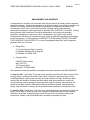

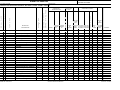


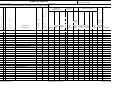


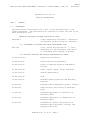


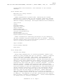

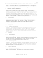
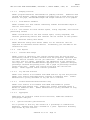

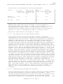
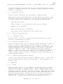

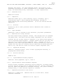


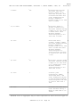

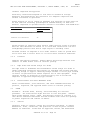


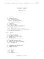
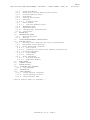


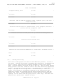

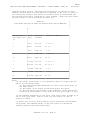


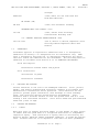


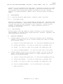


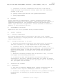

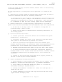

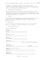


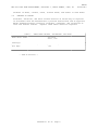


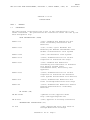

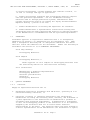
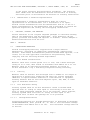

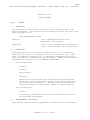


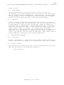
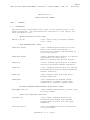

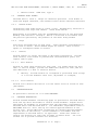


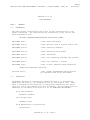

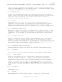


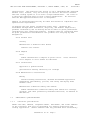
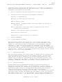


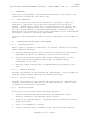


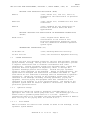


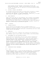

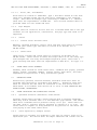
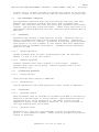

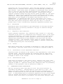
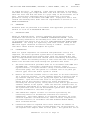
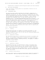

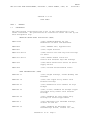


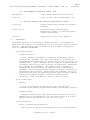
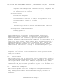

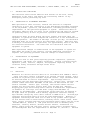


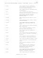


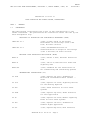

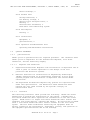


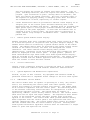
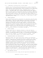


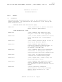


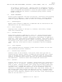


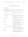

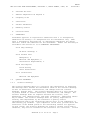


![010003E - [PROJECT.TOC] - TMG Construction Corporation](http://vs1.manualzilla.com/store/data/006000704_1-51daa2ac67e6ebfb9337b1b072f623df-150x150.png)
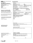


![1127117 - [PROJECT.TOC] - Performance Heating & Plumbing](http://vs1.manualzilla.com/store/data/005895106_1-55e9d6c83dbc31a8ba61d6bb401245cf-150x150.png)