1
MAC ® 1200
resting ECG analysis system
Operator's Manual
Version 1.2
227 492 04 USA
Revision F
Trademarks — Revision History
The information contained in this manual describes version 1.2 of the MAC® 1200 resting ECG analysis system and
reflects software version 5.21.
Copyright 2001 GE Medical Systems Information Technologies, Inc. All rights reserved.
Trademarked names appear throughout this document. Rather than list the names and entities that own the trademarks or
insert a trademark symbol with each mention of the trademarked name, the publisher states that it is using the names only
for editorial purposes and to the benefit of the trademark owner with no intention of improperly using the trademark.
900 SC, ACCUSKETCH, AccuVision, APEX , AQUA-KNOT, ARCHIVIST, Autoseq, BABY MAC, C Qwik Connect,
CardioServ, CardioSmart, CardioSys, CardioWindow, CASE, CD TELEMETRY, CENTRA, CHART GUARD, CINE
35, COROLAN, CORO, COROMETRICS, Corometrics Sensor Tip, CRG PLUS, DASH, Digistore, Digital DATAQ, E
for M, EAGLE, Event-Link, FMS 101B, FMS 111, HELLIGE, IMAGE STORE, INTELLIMOTION, IQA, LASER SXP,
MAC, MAC-LAB, MACTRODE, MARQUETTE, MARQUETTE MAC, MARQUETTE MEDICAL SYSTEMS,
MARQUETTE UNITY NETWORK, MARS, MAX, MEDITEL, MEI, MEI in the circle logo, MEMOPORT,
MEMOPORT C, MINISTORE, MINNOWS, Monarch 8000, MULTI-LINK, MULTISCRIPTOR, MUSE, MUSE CV,
Neo-Trak, NEUROSCRIPT, OnlineABG, OXYMONITOR, Pres-R-Cuff, PRESSURE-SCRIBE, QMI, QS, Quantitative
Medicine, Quantitative Sentinel, RAC, RAMS, RSVP, SAM, SEER, SILVERTRACE, SOLAR, SOLARVIEW, Spectra
400, Spectra-Overview, Spectra-Tel, ST GUARD, TRAM, TRAM-NET, TRAM-RAC, TRAMSCOPE, TRIM KNOB,
Trimline, UNION, STATION, UNITY logo, UNITY NETWORK, Vari-X, Vari-X Cardiomatic, VariCath, VARIDEX,
VAS, and Vision Care Filter are trademarks of GE Medical Systems Information Technologies, Inc., registered in the
United States Patent and Trademark Office.
12SL, 15SL, Access, AccuSpeak, ADVANTAGE, BAM, BODYTRODE, Cardiomatic, CardioSpeak, CD
TELEMETRY®-LAN, CENTRALSCOPE, Corolation, Dash Port Docking Station, Dash Responder, EK-Pro, EDIC,
Event-Link Cumulus, Event-Link Cirrus, Event-Link Nimbus, HI-RES, ICMMS, IMAGE VAULT, IMPACT.wf, INTERLEAD, LIFEWATCH, Managed Use, MARQUETTE PRISM, MARQUETTE® RESPONDER, MENTOR, MicroSmart,
MMS, MRT, MUSE CardioWindow, NST PRO, NAUTILUS, OCTANET, O2 SENSOR, OMRS, PHi-Res, Premium,
Prism, QUIK CONNECT V. QUICK CONNECT, QT Guard, SMARTLOOK, SMART-PAC, Spiral Lok, Sweetheart,
UNITY, Universal, Waterfall, and Walkmom are trademarks of GE Medical Systems Information Technologies, Inc.
Revision History
This manual is subject to the GE Medical Systems Information Technologies change order service. The revision letter
which follows the document part number, changes with every update of the manual.
Part No./ Revision
Date
Comment
227 492 04-A
1999-01
Initial Release
227 492 04-B
1999-03
ECO 061 952
227 492 04-C
1999-05
ECO 062 136
227 492 04-D
1999-10
ECO 062 920
227 492 04-E
2001-02
ECO 064 323
227 492 04-F
2001-10
ECO 068 399
2
MAC® 1200
227 492 04-F
MAC 1200 Option Codes
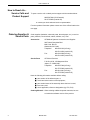
MAC 1200 Option Codes
In addition to the software supplied with the unit, optional programs may be purchased to upgrade the MAC
1200 performance features. In order to use a new option, you need to activate it by entering the option code
number (refer to section 9.8 for details). The option codes are entered into the MAC 1200 prior to shipping.
Software package
Functionality
Option Code
MEAS
measurement (measurement of the
10-second resting ECG)
____________
DIAG
interpretation (interpretation of the
10-second resting ECG)
____________
MEMO
memory (storage of a maximum of 40
10-second resting ECGs)
____________
C100
activates the three options MEAS, DIAG,
MEMO for a maximum of 100 ECGs
____________
C500
activates the three options MEAS, DIAG,
MEMO for a maximum of 500 ECGs
____________
EVAL
activates the three options MEAS, DIAG,
MEMO for a maximum of 4 weeks
____________
Serial No:
227 492 04-F
_________
MAC® 1200
3
How to Reach Us
How to Reach Us...
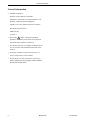
Service Calls and
Product Support
To open a service call or obtain product support call the numbers below:
800.558.7044 (US & Canada)
561.575.5000 (outside US)
or contact your local sales and service representative.
For other product information please contact one of the offices listed on the
next page.
Ordering Supplies &
Service Parts
Order supplies (leadwires, electrode paste, thermal paper, etc.) or service
parts (manuals, circuit boards, cables, software, etc.) from:
Accessories
GE Medical Systems Accessories and Supplies
2607 North Grandview Blvd.
Mail Code: SN-471
Waukesha, WI 53188
Telephone:
800.558.5102 (US only)
262.521.6856 (outside US)
Fax:
800.232.2599 (US only)
262.521.6855 (outside US)
Service Parts
GE Clinical Services
P.O. Box 9100, 100 Marquette Drive
Jupiter, FL 33468-9100
Telephone:
800.558.7044 (US only)
561.575.5000 (outside US)
Fax:
800.421.6841 (US only)
561.575.5050 (outside US)
Have the following information available before calling:
■
part number of the defective part, or
■
model and serial number of the equipment,
■
part number/name of the assembly where the item is used,
■
item name, and
■
where applicable, reference designation (eg. R13, S12)
Ordering Manuals When ordering additional operator manuals, be sure
to include the software version of the product.
4
MAC® 1200
227 492 04-F
How to Reach Us
Other Questions or
Problems
For additional information contact one of the offices listed below or see our
website at www.gemedicalsystems.com
Headquarters
GE Medical Systems Information Technologies
8200 West Tower Avenue
Milwaukee, Wisconsin 53223, USA
Telephone:
414.355.5000 or 800.558.5120 (US only)
Fax
414.355.3790
Europe
GE Medical Systems Information Technologies
Postfach 60 02 65
D-79032 Freiburg Germany
Telephone:
+49.761.4543.0
Fax:
+49.761.4543.233
Australia
GE Medical Systems (Australia) Pty Ltd.
13 South Street
Rydalmere NSW 2116
Australia
Telephone:
+61.2.9975.5501
Fax:
+61.2.9975.5503
Japan
GE Medical Systems, Japan
67-4 Takakura-cho
Hachiojii-shi, Tokyo 192-003, Japan
Telephone:
+81.42.648.2944
+0120-055-919 (toll free inside Japan only)
Fax:
+81.42.648.2902
Hong Kong
GE Medical Systems Hong Kong Limited
th
11 Floor, The Lee Gardens
33 Hysan Avenue
Causeway Bay, Hong Kong
Telephone:
+852.2100.6300
Fax:
+852.2100.6292
Southeast Asia
GE Pacific
298 Tion Bahru Road #15-01/06
Central Plaza, Singapore 168730
Telephone:
+65.277.7620
Fax:
+65.277.7600
227 492 04-F
MAC® 1200
5
General Information
General Information
• Standards compliance:
European Council Directive 93/42/EEC
IEC60601-1-2/EN 60601-1-2 "Electromagnetic Compatibility - Medical Electrical Equipment"
CISPR11 / EN 55011 "Radio interference emission"
IEC 60601, protection class I
MDD class IIa
UL 2601-1
• The symbol
means: Consult accompanying
documents. It indicates points which are of particular
importance in the operation of the device.
• The warranty does not cover damage resulting from the
use of accessories and consumables from other manufacturers.
• On request GE Medical Systems Information Technologies will provide a service manual.
• The GE Medical Systems Information Technologies
quality management system complies with the standards
EN ISO 9001 and EN 46001.
6
MAC® 1200
227 492 04-F
Contents
1
INTENDED USE AND FUNCTIONAL DESCRIPTION .....................................................................9
2
CONTROLS AND INDICATORS ........................................................................................................10
3
PUTTING THE DEVICE INTO OPERATION AND PERFORMANCE TEST .............................12
3.1
3.2
3.3
3.4
3.5
3.6
4
PREPARATIONS FOR ECG RECORDING.......................................................................................20
4.1
4.2
4.3
4.4
5
SOME BASIC FACTS ...........................................................................................................................43
RECORDING .......................................................................................................................................44
BRIEF OPERATING INSTRUCTIONS - ARRHYTHMIA MODE ...............................................................46
ECGS OF PACEMAKER PATIENTS / ECG RECORDING DURING DEFIBRILLATION.......47
8.1
8.2
9
SOME BASIC FACTS ...........................................................................................................................40
RECORDING .......................................................................................................................................40
BRIEF OPERATING INSTRUCTIONS - 6 LEAD MODE ..........................................................................42
ARRHYTHMIA MODE.........................................................................................................................43
7.1
7.2
7.3
8
SOME BASIC FACTS ...........................................................................................................................26
RECORDING .......................................................................................................................................27
THE STORAGE PROGRAM ...................................................................................................................29
THE REPORT FORMATS ......................................................................................................................31
ECG TRANSMISSION .........................................................................................................................32
BRIEF OPERATING INSTRUCTIONS - 12 LEAD MODE .........................................................................39
RECORDING IN 6 LEAD MODE ........................................................................................................40
6.1
6.2
6.3
7
CONNECTING THE PATIENT CABLE....................................................................................................20
APPLYING THE ELECTRODES .............................................................................................................21
ARTIFACT DUE TO POOR ELECTRODE APPLICATION.........................................................................23
ENTERING PATIENT DATA .................................................................................................................24
RECORDING IN 12 LEAD MODE ......................................................................................................26
5.1
5.2
5.3
5.4
5.5
5.6
6
SAFETY INFORMATION.......................................................................................................................12
POWER SUPPLY ..................................................................................................................................16
INSTALLATION AND MAINS CONNECTION .........................................................................................17
PERFORMANCE CHECK ......................................................................................................................17
SYSTEM SETUP ..................................................................................................................................18
CONNECTING EXTERNAL DEVICES ....................................................................................................19
RECORDING ECGS OF PACEMAKER PATIENTS ..................................................................................47
ECG RECORDING DURING DEFIBRILLATION.....................................................................................47
SYSTEM SETUP.....................................................................................................................................48
9.1
9.2
9.3
9.4
9.5
9.6
9.7
9.8
SOME BASIC FACTS ...........................................................................................................................48
12 LEAD MODE ..................................................................................................................................48
6 LEAD MODE ....................................................................................................................................50
ARRHYTHMIA MODE .........................................................................................................................51
SYSTEM SETUP PARAMETERS ............................................................................................................52
COMMUNICATION ..............................................................................................................................53
CONFIGURATION OF PATIENT DATA MENU .......................................................................................54
OPTION CODE ....................................................................................................................................55
227 492 04-F
MAC® 1200
7
Contents
9.9
9.10
ECG TRANSMISSION VIA MODEM .....................................................................................................55
DIRECT ECG TRANSMISSION ............................................................................................................56
10
LOADING CHART PAPER ...............................................................................................................57
11
CLEANING, DISINFECTION AND MAINTENANCE .................................................................59
11.1
11.2
11.3
11.4
CLEANING AND DISINFECTING THE RECORDER HOUSING .................................................................59
CLEANING AND DISINFECTING THE PATIENT CABLE .........................................................................59
CLEANING AND DISINFECTING THE ELECTRODES .............................................................................59
MAINTENANCE...................................................................................................................................60
12
TROUBLESHOOTING......................................................................................................................61
13
TECHNICAL SPECIFICATIONS....................................................................................................63
APPENDIX
ENTERING SPECIAL CHARACTERS
INDEX
8
68
69
MAC® 1200
227 492 04-F
Intended Use and Functional Description
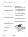
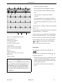
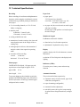
1 Intended Use and Functional Description
The MAC 1200 is an ECG acquisition and recording
system designed and manufactured by GE Medical
Systems Information Technologies.
− It is intended to be used for resting ECG recording and realtime ECG recording with or
without arrhythmia detection.
− It is not intended for use as a vital signs physiological monitor.
− The arrhythmia detection portion of the MAC
1200 is provided to the customer for the convenience of automatic documentation. It is not designed to provide alarms for arrhythmia detection.
− The MAC 1200 offers no diagnostic opinion to
the user. Instead it provides analytical statements
when configured with the appropriate options.
− It is intended to be used by trained operators
under direct physician supervision when ECG records are required.
− It is not suitable for intracardiac application.
− It is designed for continuous operation.
− It is not intended for home use.
− The MAC 1200 is designed as a portable device
and can easily be moved from one patient to another or to different locations. It is not intended
to be used during patient transport.
Resting ECGs can be transferred to the MUSE CV
Information System via the RS232 interface.
The device operates from both AC and DC (rechargeable batteries) power sources.
The unit's performance features can be upgraded
with the following optional programs:
− MEAS - measurement (measurement of the 10second resting ECG)
− DIAG - interpretation (interpretation of the 10second resting ECG)
− MEMO - memory (storage of a maximum of 40
10-second resting ECGs)
- C100 - activates the three options MEAS, DIAG,
MEMO for a maximum of 100 ECGs
- C500 - activates the three options MEAS, DIAG,
MEMO for a maximum of 500 ECGs
- EVAL - activates the three options MEAS,
DIAG, MEMO for a period of 4 weeks
The MAC 1200 resting ECG analysis system has a
setup menu to customize the system parameters.
Patient and user data can be entered for reliable and
safe archiving of patient records. The patient name is
annotated on each printed report page. All other data
is printed on request.
Equipped with the standard software, the MAC 1200
supports the following operating modes:
12
− 12 Lead Mode (acquisition of 12 leads of ECG
for a period of 10 seconds),
− 6 Lead Mode (real-time recording of 6 ECG
leads), and
− Arrhythmia Mode (continuous ECG analysis for
arrhythmias).
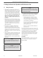
y
6
cop
t/
formaed
spe
d
I
5
4
3
2
1
Q
W
!
A
on f
of
MAC
E
?
S
;
Z
R
=
D
:
X
T
-
F
/
C
U
Y
*
+
G
,
V
H
.
B
%
J
rt
sta
p
sto
pat
info
X
)
L
(
7
6
arr
re/
sto ieve
retr
gain
P
9
O
8
hy
lea
e
scl
mufilter
up
set
0
K
>
<
M
ery
N
low
batt
dby
stan
alt
1200
The graphics display shows 3 leads at a time.
Figure 1-1. MAC 1200
227 492 04-F
MAC® 1200
9
Controls and Indicators
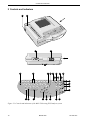
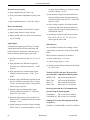
2 Controls and Indicators
1
2
12
copy
t/
d
forma
spee
9
I
6
5
T
4
3
R
E
2
W
1
Q
/
C
:
X
;
Z
on f
of
-
F
=
D
?
S
!
A
*
+
G
,
V
H
.
B
)
L
(
%
J
stop
pat o
inf
X
K
>
<
M
tery
N
low
bat
y
ndb
sta
alt
MAC
1200
3
5
U
Y
4
6
7 8
9
11
13 15
10 12
1
Q
on
stdby
W
!
2
3
E
=
?
A
S
Z;
R
D
X:
C/
4
5
T
Y
+
-
,
V
6
B
.
8
7
J
N
<
O
I
U
H*
G
F
t
star
P
O
8
y
arrh
re/
sto rieve
ret
gain
0
7
6
d
lea
scle
mufilter
setup
%
K
(
9
P
L
0
)
setup
X
>
M
14
12
format/
speed
copy
muscle
filter
lead
gain
store/
retrieve
6
arrhy
16
17
18
start
alt
19
pat
info
stop
standby
27 26
25
24 23
battery low
22
21 20
Figure 2-1. Controls and indicators of the MAC 1200 resting ECG analysis system
10
MAC® 1200
227 492 04-F
Controls and Indicators
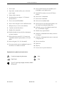
1
Power input
2
Paper door, windows allows you to check the
paper supply
3
Patient cable connector
4
Serial interface (see chapter 13 "Technical
Specifications")
14 Selects the ECG lead in 6 Lead Mode (in 12
Lead Mode, on the display only)
15 Sends ECG to memory/retrieves ECG from
memory
16 Selects the 12 Lead Mode
17 Selects the 6 Lead Mode
5
Power switch (ON/STANDBY)
18 Selects the Arrhythmia Mode
6
Keys to select a higher or lower HR alarm limit
7
Backspace key (to correct entered data)
19 Starts/stops the selected operating mode, exits
the setup menu and patient data entry
8
Confirms entered data (Enter)
9
Displays the setup menu
20 Indicators, green: selected mode started, amber: selected mode stopped
21 Enables entry of patient data
10 Enables/disables the muscle filter (elimination
of muscle artifact)
11 Selects the writer speed (25, 50, 5 mm/s) in 6
Lead Mode and the report formats in 12 Lead
Mode
22 Indicator is illuminated when battery needs to
be charged
23 Indicator is illuminated when unit is connected
to the power line
24 Cursor control keys
12 Selects the gain (5, 10, 20, 40 mm/mV)
13 Press to print the report or additional copies of
the ECG, or to send/receive ECGs
25 Space bar
26 Shift key
27 Press to access special characters
Explanation of symbols used on the device
Consult accompanying documents
Start
Signal input
Stop
Type CF signal input, highly insulated, defibrillation-proof
227 492 04-F
MAC® 1200
11
Putting the Device into Operation and Performance Test
3 Putting the Device into Operation and Performance Test
3.1
Safety Information
• This manual is an integral part of the device. It
should always be kept near the device. Close observance of the information given in the manual
is a prerequisite for proper device performance
and correct operation and ensures patient and operator safety. Please note that information pertinent to several chapters is given only once.
Therefore, carefully read the manual once in
its entirety.
Caution
indicates a potentially hazardous situation which, if
not avoided, may result in minor or moderate injury
or product/property damage.
• GE Medical Systems Information Technologies is
responsible for the effects on safety, reliability,
and performance of the device, only if
− assembly operations, extensions, readjustments, modifications, or repairs are carried
out by persons authorized by GE Medical Systems Information Technologies,
• Patient safety, the specified measuring accuracy,
and interference-free operation can be guaranteed
only if original GE Medical Systems Information
Technologies components are used. The user is
responsible for application of accessories from
other manufacturers.
• This manual is in conformity with the device
specifications and standards on safety of electromedical equipment valid at the time of printing.
All rights are reserved for devices, circuits, techniques, software programs, and names appearing in
this manual.
• The terms danger, warning, and caution are used
throughout this manual to point out hazards and
to designate a degree or level of seriousness.
Hazard is defined as a source of potential injury
to a person.
Danger
indicates an imminently hazardous situation which,
− the electrical installation of the relevant room
complies with the requirements of the appropriate regulations, and
− the device is used in accordance with the instructions for use.
The safety statements presented in this chapter refer
to the equipment in general and, in most cases, apply
to all aspects of the device. There are additional
safety statements in the other chapters that are
specific to the topic described. The order in which
safety statements are presented in no way implies
order of importance.
DANGERS
EXPLOSION HAZARD — Do not use this equipment in the presence of flammable anesthetics,
vapors or liquids.
if not avoided WILL result in death or serious injury.
Warning
indicates a potentially hazardous situation which, if
not avoided, COULD result in death or serious injury.
12
MAC® 1200
227 492 04-F
Putting the Device into Operation and Performance Test
WARNINGS
ACCESSORIES (SUPPLIES) — Use only the
original GE Medical Systems Information Technologies cables. Do not connect other signal sources to
the cables. The user is responsible for the use of
accessories from other manufacturers.
ACCIDENTAL SPILLS — To avoid electric shock
or device malfunction liquids must not be allowed to
enter the device. If liquids have entered a device,
take it out of service and have it checked by a service technician before it is used again.
BEFORE USE — Before putting the system into
operation visually inspect all connecting cables for
signs of damage. Damaged cables and connectors
must be replaced immediately.
BEFORE USE — Before using the device, the
operator must verify that it is in correct working
order and operating condition. For instructions, refer
to section 3.4 “Performance Check” in this chapter.
CONDUCTIVE CONNECTIONS — Do not allow
electrodes to come into contact with conductive
parts. The neutral electrode, in particular, must not
be connected to earth.
MPSO—The use of a multiple portable socket outlet
(MPSO) for a system will result in an enclosure
leakage current equal to the sum of all individual
earth leakage currents of the system if there is an
interruption of the MPSO protective earth conductor. Do not use an additional extension cable with
the MPSO as it will increase the chance of the single
protective earth conductor interruption.
OPERATOR — The user must have received adequate training in the use of the MAC 1200 and must
be capable of applying it properly.
POWER SUPPLY — The device must be connected
to a properly installed power outlet with protective
earth contacts only. If the installation does not
provide for a protective earth conductor, disconnect
the device from the power line and operate it on
battery power, if possible.
If the installation of this equipment in the USA will
use 240V rather than 120V, the source must be a
center-tapped, 240V, single phase circuit.
DISCONNECTION FROM MAINS — When disconnecting the system from the power line, remove
the plug from the wall outlet first. Then you may
disconnect the power cord from the device.
EMERGENCY APPLICATION If the MAC
1200 is used as an emergency device, a second ECG
recorder must be available.
MOISTURE CONDENSATION — Devices intended for emergency application must not be stored
or transported at temperatures which cause moisture
condensation at the application site. Wait until all
moisture condensation has evaporated before using
the device.
227 492 04-F
MAC® 1200
13
Putting the Device into Operation and Performance Test
CAUTIONS
DEFIBRILLATOR PRECAUTIONS — Patient
signal inputs labeled with the CF and BF symbols
with paddles are protected against damage resulting
from defibrillation voltages To ensure proper defibrillator protection, use only the recommended
cables and leadwires. Proper placement of defibrillator paddles in relation to the electrodes is required to
ensure successful defibrillation.
DISPOSAL — Dispose of the packaging material,
observing the applicable waste control regulations
and keeping it out of children’s reach.
ELECTROCAUTERY PRECAUTIONS — To
prevent unwanted skin burns, apply electrocautery
electrodes as far as possible from all other electrodes, a distance of at least 15 cm/ 6 in. is recommended.
EMC — Magnetic and electrical fields are capable
of interfering with the proper performance of the
device. For this reason make sure that all external
devices operated in the vicinity of the MAC 1200
comply with the relevant EMC requirements. X-ray
equipment or MRI devices are a possible source of
interference as they may emit higher levels of electromagnetic radiation.
MAINTENANCE — Regular preventive maintenance should be carried out annually, inspections of
equipment with measuring functions should be done
every two years (refer to chapter 11 “Cleaning,
Disinfection and Maintenance”).
PERFORMANCE CHECKS — Check the device
performance once a month, strictly following the
instructions outlined in section 3.4 “Performance
Check”.
POWER REQUIREMENTS — Before connecting
the device to the power line, check that the voltage
and frequency ratings of the power line are the same
as those indicated on the unit’s label. If this is not
the case, do not connect the system to the power line
until you adjust the unit to match the power source.
RESTRICTED SALE — U.S. Federal law restricts
this device to sale by or on the order of a physician.
VENTILATION REQUIREMENTS — Set up the
device in a location which affords sufficient ventilation. The ventilation openings of the device must not
be obstructed. The ambient conditions specified in
the technical specifications must be ensured at all
times.
INTERFACING OTHER EQUIPMENT — Devices
may only be interconnected with each other or to
parts of the system when it has been determined by
qualified biomedical engineering personnel that
there is no danger to the patient, the operator, or the
environment as a result. In those instances where
there is any element of doubt concerning the safety
of connected devices, the user must contact the
manufacturers concerned (or other informed experts)
for proper use. In all cases, safe and proper operation
should be verified with the applicable manufacturer’s instructions for use, and system standards
IEC 60601-1-1/EN 60601-1-1 must be complied
with.
14
MAC® 1200
227 492 04-F
Putting the Device into Operation and Performance Test
NOTES
Literature
- The MAC 1200 is designed to comply with IEC
60601/ EN 60601 requirements. It is Class I
equipment/equipment with a built-in rechargeable
electrical power source. The device is not suitable for intracardiac use. The device is suitable
for continuous operation.
- Choose a location which affords an unobstructed
view of the display screen and easy access to the
operating controls.
- The MAC 1200 has no additional protection
against ingress of water.
- Medical technical equipment such as the MAC
1200 must only be used by persons who have received adequate training in the use of such
equipment and who are capable of applying it
properly.
- At the end of its service life; the MAC 1200 and
its accessories must be disposed of in compliance
with the special waste control regulations for
electronic parts. If you have any questions in this
matter, please contact GE Medical Systems Information Technologies.
227 492 04-F
Medical Device Directive 93/42/EEC
EN 60601-1/1990 + A1: 1993 + A2: 1995: Medical
electrical equipment. General requirements for
safety
EN 60601-1-1/9.1994 + A1 12.95: General requirements for safety. Requirements for the safety of
medical electrical systems. Requirements for the
safety of medical electrical systems.
EN 60601-2-25/1993: Medical electrical equipment.
Part 2: Special requirements for the safety of electrocardiographs.
IEC Publication 513/1994: Fundamental aspects of
safety standards for medical equipment.
MAC® 1200
15
Putting the Device into Operation and Performance Test
3.2
format/
speed
pat
info
standby
23
battery low
22
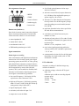
Figure 3-1. Indicators
store/
retrieve
Power Supply
The units are powered from the power line or from
the rechargeable battery.
The battery charges automatically when the unit is
connected to the power line. It is not necessary to
turn on the device for charging. As soon as the
device is connected to the power line, the standby
indicator 23 lights up (Figure 3-3). To ensure that
the battery is always fully charged, leave the MAC
1200 resting ECG analysis system connected to the
power line whenever possible. After 4 hours the
battery has regained its full capacity.
The battery low indicator 22 is illuminated when
battery needs to be charged. The unit can also be set
up to emit an additional audio signal when the
battery requires charging.
With a full battery, about 50 ECGs (1 page) can be
recorded in 12 Lead Mode. When its capacity drops
to about 25 recordings, the battery is used up and
must be replaced by a service specialist.
Note
To prolong the battery life, discharge the battery at
least once per month (by operating the resting ECG
analysis system on battery power).
Note
In standby mode, a fully charged battery is drained
within approx. 4 hours. Therefore, when operating
the device on battery power, be sure to turn it off
when it is not in use.
16
MAC® 1200
227 492 04-F
Putting the Device into Operation and Performance Test
3.3
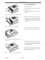
Installation and Mains Connection
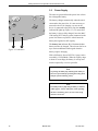
Figure 3-2 shows a practical arrangement of patient
and recorder. For interference-free operation, it is
important that the patient cable and the power cord
do not run parallel.
•
Figure 3-2. Arranging device and couch
Using the power cord, connect the device to the
power line (Figure –3-1). Use only the original
power cord or an equivalent cable.
The standby indicator 23 will illuminate.
•
Check the paper supply (the window in the paper
door allows you to look inside the compartment).
If it is necessary to insert a new paper pad, refer
to chapter 10 for instructions.
3.4
•
Figure 3-3. AC power input
1
Q
on
stdby
W
A!
2
Z;
4
E
5
R
D
X:
Press the power switch to switch on the device
(Figure 3-4).
The amber stop indicator
3
S?
Performance Check
=
C/
F
T
-
Y
G
,
V
+
6
H*
.
B
<
N
20 will illuminate.
After power-up, the resting ECG analysis system
runs an automatic self-test. When no problem is
detected, it defaults to the 12 Lead Mode. If a malfunction is identified, the display will show an error
message “Error...”. In this situation, notify service to
check and repair the device.
The self-test can be aborted with the
alt
R
4
button. In
this case, the device immediately activates the 12
Lead Mode.
Contrast Adjustment
Figure 3-4. Power switch
•
Note
– When turning off the MAC 1200 (standby mode),
be sure to press the power switch long enough.
alt
To adjust the contrast, simultaneously press
and the appropriate cursor key:
for more contrast,
for less contrast.
– The backlighting of the display switches off
automatically when no key is activated for 5
minutes (adjustable).
– Run the full self-test at least once a day to ensure
that the device is functioning properly.
227 492 04-F
MAC® 1200
17
Putting the Device into Operation and Performance Test
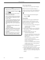
3.5
Parameter
System Defaults Options
Ordering Physician
No
selection from a list
of 10 names
Referring Physician
No
selection from a list
of 10 names
Technician
No
selection from a list
of 10 names
Institution Name
empty text box text box (40 chrs)
Cart #
1
1 to 9999
Site # (for CSI
protocol only)
1
1 to 255
Location #
blank
1 to 600
Date
(dd.mm.yyyy)
current date
Time (hh:mm)
current time
Lead Fail Beep
No
Yes
High HR Beep
No
Yes
Lead Labels
AAMI
IEC
Pace EnhanceYes
ment
Baseline roll filter 0.08 Hz
Date
mm/dd/yyyy
0.04 Hz, 0.16 Hz
dd.mm.yyyy
Time
12
24
Units
in, lb
cm, kg
Mains
60 Hz
50 Hz
LCD light off
after
5 min
1 to 99 minutes
Low battery beep
0 (Off)
Default mode
12 Lead
5 s to 60 s (5 s =
beep at 5-s interval)
6 Lead,
Arrhythmia
Language
English
English, French,
Spanish
Enable password
No
Yes
Test DATA
No
Yes
Restore defaults
No
Yes
Print setup lists
No
Yes
18
System Setup
The table at left shows the system setup parameters
that can be modified and the system defaults.
For instructions on changing the device setup, refer
to section 9.5 "System Setup".
No
MAC® 1200
227 492 04-F
Putting the Device into Operation and Performance Test
3.6
Warning
Shock Hazard — Strictly observe the following
warnings. Failure to do so may endanger the lives of
the patient, the user and bystanders.
− Connecting peripheral devices to the RS232 interface of the resting ECG analysis system creates a medical system. This system must meet the
requirements of IEC 60601-1-1.
− Use only the original GE Medical Systems Information Technologies connection cables.
− All non-medical devices of a system must be
connected to the same electric circuit. Devices
which are not connected to the same circuit must
be electrically isolated (use isolated RS232 interface as per IEC 60601-1).
Connecting External Devices
Via the serial interface, the resting ECG analysis
system can be connected to a MUSE CV Information System. These external devices can be connected directly or via a modem. Please contact GE
Medical Systems Information Technologies Application Support for details. Resting ECGs acquired in
the 12 Lead Mode as well as the corresponding data
can be transferred to these external devices (see
section 5.5 "ECG Transmission").
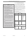
The table below shows the system defaults and all
possible adjustments.
For instructions on changing the default setup, refer
to section 9.6 "Communication".
Parameter
System defaults Options
Choices for "Modem → Other"
− A PC connected to the resting ECG analysis system should meet the requirements of EN 60601.
If it doesn't, it must be set up outside the patient
environment. If the PC fulfills the requirements
of EN 60950, it must be set up within the medically used area, but outside the patient environment.
− Do not connect PCs to the resting ECG analysis
system that fulfill neither EN 60601 nor EN
60950.
− Modems connected to the resting ECG analysis
system must meet the requirements of EN 60950
or UL1950 (all modems recommended by GE
Medical Systems Information Technologies meet
these requirements). The specific regulations
valid in your country must also be observed.
The modem must be set up within the medically
used area, but outside the patient environment.
227 492 04-F
none
user-defined
MultiTech 19.2
MultiTech 56k
Elsa 14.4
Elsa 28.8
Elsa 33.6
Elsa 56k
Choices for "Modem → user-defined"
telephone
init string
dial string
hangup
AT&FM1X3S
0=1V0
ATDT
+++ATH
Choices for "Modem → MultiTech 19.2, 56k,
ELSA 14.4, 28.8, 33.6, 56k"
dial mode
phone
outside line
MAC® 1200
tone
pulse
0 to 9 (28 digits)
0 to 9 (20 digits)
19
Preparations for ECG Recording
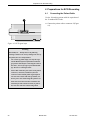
4 Preparations for ECG Recording
4.1
Connecting the Patient Cable
Use the 10-leadwire patient cable for acquisition of
the 12 standard ECG leads.
3
•
Connect the patient cable to connector 3 (Figure
4-1).
!
Figure 4-1. ECG signal input
Warning
Shock Hazard — Strictly observe the following
warnings. Failure to do so may endanger the lives of
the patient, the user and bystanders.
− For reasons of patient safety, use only the original GE Medical Systems Information Technologies patient cable. Before connecting the cable to
the device, check it for signs of mechanical damage. Do not use a damaged cable.
− Ensure that conductive parts (such as the patient,
connectors, electrodes, transducers) that are
connected to the isolated patient signal input do
not come into contact with other grounded, conductive parts. This would bridge the patient's isolation and cancel the protection provided by the
isolated input. The neutral electrode, in particular, must not come into contact with ground.
20
MAC® 1200
227 492 04-F
Preparations for ECG Recording
4.2
Applying the Electrodes
Careful application of the electrodes and skin preparation is the key to an interference-free ECG.
Caution
Use only silver-silver chloride electrodes, if the patient may have to be defibrillated. (Refer to chapter
8.2 “ECG Recording during Defibrillation”.)
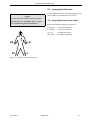
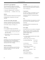
4.2.1 Applying Electrodes (Limb Leads)
Refer to the illustration shown in Figure 4-2.
RA (white)
LA (black)
LL (red)
RL (green)
RA
RL
V
electrode on right arm
electrode on left arm
electrode on left leg
electrode on right leg
LA
LL
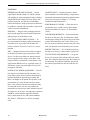
Figure 4-2. Applying limb-lead electrodes
227 492 04-F
MAC® 1200
21
Preparations for ECG Recording
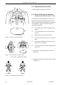
4.2.2 Applying Electrodes (Thorax)
•
4.2.3 Electrode Placement for Standard
Leads (l, II, III, aVR, aVL, aVF, V1...V6)
V2
V3
V1
V5
V4
V6
For acquisition of the standard ECG leads four electrodes must be applied on the limbs and six on the
chest. The limb electrodes should be placed above the
wrists and ankles. Figure 4-3 shows the chest electrode application points.
V6
Figure 4-3. Chest electrode placement
RA white
V1
4th intercostal space at the right border of the
sternum
V2
4th intercostal space at the left border of the
sternum
V3
midway between locations V2 and V4
V4
at the mid-clavicular line in the 5th intercostal
space
V5
at the anterior axillary line on the same horizontal level as V4 and V6
V6
at the mid-axillary line on the same horizontal
level as V4
V5
V1 V2 V3 V4
RL green
right leg
right arm
V1 red
V1
V2 yellow
Shave application points, if necessary.
V2
V3
V3 green
V5
V4
V6
V4 blue
V5 orange
V6 purple
LA black
left arm
LL red
V6
•
left leg
V1 V2 V3 V4
V5
Connect the 10-lead patient cable as shown in
Figure 4-4.
Figure 4-4. Connecting the patient cable
(10-lead cable, standard ECG leads)
•
correct
Arrange the leadwires and patient cable as shown
in Figure 4-5.
wrong
Figure 4-5. Arranging the patient cable
22
MAC® 1200
227 492 04-F
Preparations for ECG Recording
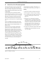
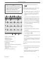
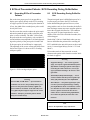
4.3
Artifact Due to Poor Electrode Application
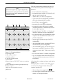
The resting ECG analysis system is equipped with
state-of-the-art electronic utilities that ensure artifact-free recordings. Among these are the automatic
baseline adjustment and the anti-drift system (ADS
or cubic spline).
At the beginning of the recording the automatic
baseline adjustment algorithm verifies the incoming
signal and adjusts the baseline position accordingly.
During the recording, the anti-drift system (cubic
spline) continuously checks the baseline position
and returns it to the normal level, if required (Figure
4-6).
On the display this condition is indicated by ****
instead of the electrode label (e.g. at i, Figure 5-1).
Remedy
•
•
•
•
For the 6 Lead Mode, the anti-drift system (cubic
spline) can be enabled and disabled from the setup
menu, in the 12 Lead and Arrhythmia Modes, it is
always enabled.
When electrodes are not properly applied, these
measures may not fully compensate for artifact.
High polarization voltages induced by electrodes
applied without conductive gel may cause the amplifier to overrange, so that a straight line will be
recorded instead of the ECG (see Figure 4-6). The
device will then automatically block and return the
baseline to its normal position. A baseline is then
recorded for approx. 1 second. It is possible to block
the amplifiers manually by disconnecting the RL
electrode.
•
Apply the electrodes according to instructions.
Do not apply the electrodes on top of clothing.
Use a contact agent with reusable electrodes (e.g.
moistened electrode paper, electrode cream,
spray, etc.).
Wait approx. 10 seconds before initiating a
recording. After the 10-second period, the automatic functions are enabled and the polarization
voltages have stabilized, provided the electrodes
are properly applied. In case of improper electrode application, an error message will appear
on the display (RL, LL, LA, LL, V1 to V6).
If required, the ADS (cubic spline) and the filters
(20/40 Hz, 60 Hz) can be disabled to verify the
“raw” ECG signal.
approx.1 s
Figure 4-6. Sample recording
227 492 04-F
MAC® 1200
23
Preparations for ECG Recording
4.4
Parameter
Factory Default
adjusted
Menu
item
displayed
New Patient
No
Yes
Last Name
Yes
First Name
Yes
Date of Birth
00.00.0000 Yes
(mm.dd.yy
yy)
Patient ID
Yes
Secondary ID
No
Pacemaker
No
Yes
Gender
Yes
Height
No
Weight
No
Race
unknown Yes
Systolic BP
0 mmHg No
Diastolic BP
0 mmHg No
Ordering PhysiYes
cian
Referring
No
Physician
Technician
Yes
Phone No.
Medication
1.
2.
Comments
Location #
Room
Order Number
Prompt 1
Prompt 2
Prompt 3
Prompt 4
unknown
unknown
No
No
No
No
No
No
No
No
No
No
No
No
Table 4-1. Patient data entry menu
24
Entering Patient Data
It is possible to enter patient data and have them
annotated on the recording for easy archiving of
patient records.
Options
•
Yes
Yes
female, male
Press
pat
info
− The recorder displays the menu items in a defined order.
In the patient data setup menu (section 9.7 "Configuration of Patient Data Menu") you determine
the items to be included in the menu (In the table
at left, the items that appear in the patient data
menu in the default setup are marked as "Yes" in
the "Menu item displayed" column, the other
menu items are marked as "No".
− To skip a menu item, press
or
selection from a
list of 10 names
selection from a
list of 10 names
selection from a
list of 10 names
.
− When filling out alphanumeric text boxes, you
can activate the Shift-Lock function with the
button (the
format/
speed
symbol appears in the display to
indicate the Shift-Lock status).
− All entries must be confirmed with
− Press
1 to 600
or the cursor key
− It is not possible to write capital and small letters
(do not use the Shift key).
− For entry of numbers (e.g. date of birth), it is not
necessary to press the Shift key.
other
other
other
to enter the patient data mode.
pat
info
or
.
to exit the patient data
mode.
The table at left shows the menu items in the correct
order. On the display, selected options are shown in
brackets. Refer to section 9.7 for details on setting
up the patient data menu.
Note
Please refer to the Appendix for instructions on entering special characters.
New patient
Yes: existing patient data are deleted
No: entered data can be edited
MAC® 1200
227 492 04-F
Preparations for ECG Recording
Last Name / First Name
Enter the patient's last and first names (16 characters
for last name, 10 characters for first name) and
confirm entries with
Phone No.
Enter the patient's telephone number.
.
Ordering / Referring Physician / Technician
When choosing "Yes" for "New patient", the default
names entered in the General Settings will appear
here. When choosing "other", you can pick a name
from the list. It is also possible to choose "No".
Date of birth
The slash key
/
C
must be entered between
month/day/year.
Note
The
format/
speed
button has the function of the Shift-Lock
key when entering data in alphanumeric text boxes.
This function allows you to enter the characters
shown in the upper part of the keys, without pressing
the Shift key. The
Systolic BP/Diastolic BP
Enter the blood pressure readings in mmHg.
You can exit the menu with
.
The "Referring Physician" is only relevant if you
send ECGs to the MUSE CV Information System.
This name will not be annotated on the ECG recording.
symbol appears in the display to
Medication
indicate the Shift-Lock status.
Enter the patient's medications and confirm entries
with
Patient ID / Secondary ID
This field accepts 3 to 16 characters. The exact
length is determined in the patient data setup menu.
Note
When entering a patient ID which consists of numerals only, the blanks preceding the number are
replaced with 0. Example: If a 6-digit text box is
.
Comments
4 lines of 30 characters each
Location #
ID number of the sending system (3 digits). The
default value entered in System Setup will be used,
but this value can be changed.
configured and you enter the patient ID 123, the
final ID number will read “000123”.
Pacemaker
Influences the identification of pacer pulses in
Arrhythmia Mode. Enable the function ("Yes")
when recording the ECG of a pacemaker patient.
The recording will then be annotated with the message "Pacemaker Patient".
Gender/Race
If you do not intend to enter all demographic data,
select the neutral entries "-" and "unknown".
Height/Weight
Enter the patient's height (in inches) and weight (in
pounds). The weight can be entered with one decimal place.
227 492 04-F
Room
Enter the hospital room number (5 characters maximum).
Order number
Enter order number of the ECG recording, if available (9 characters maximum).
Prompts
Answer the prompts entered in the patient data setup
menu (section 9.7).
Fields on patient data entry screens that require an
entry, are identified with pointed brackets (e.g. Last
name: >............<).
MAC® 1200
25
Recording in 12 Lead Mode
5 Recording in 12 Lead Mode
Note
Please bear in mind that no automated analysis of
ECG signals is completely reliable. Therefore a physician should always overread and reassess the system interpretation before performing patient diagnosis.
Several system settings can be customized. In this
manual they are labeled "configurable".
The following information refers to a unit with the
system defaults (see table below). For instructions
on changing the system setup, refer to section 9.2
"12 Lead Mode".
Parameter
System defaults
Options
Report Sequence
STANDARD
CABRERA
Rhythm Leads
II, V1, V5
I, III,
aVR, aVL, aVF,
V2, V3, V4, V6
Gain
10 mm/mV
"*auto", 5, 20, 40
mm/mV
Report Format
4x2.5R1
1x10R12, 2x5R1,
2x5_50, 4x2.5R1,
1x10R3, 4x2.5R3
Patient Data Menu").
Detailed Results
No
Yes
Depending on the implemented software options, the
ECG
Muscle Filter
No
Yes
Muscle Filt. Freq.
40 Hz
20 Hz
AC Filter
Yes
No
Manual copy to
EKG
HOST
No. of copies
1
0 to 9
Delete ECG after
Transm.
No
Yes
Autosave ECG
No
Yes
Use Screening
criteria
No
Yes
Suppress
No
NORMAL statem.
Yes
Suppress
ABNORMAL
statm.
No
Yes
Interpretation
Yes
No
Print Interpretation
Yes
No
Override Function Yes
No
5.1
Some Basic Facts
In 12 Lead Mode, 12 leads of ECG are acquired
simultaneously for a period of 10 seconds. When
initiated with
, ECG acquisition and re-
cording proceed automatically. The system, however, may be set up to start recording only when
specific patient data (ID, Secondary ID, name) have
been entered (see section 9.7 "Configuration of
− is only printed out (options MEAS - measurement -, DIAG - interpretation - not implemented)
− is measured and printed out with the measurement results (with option MEAS - measurement)
− is measured, interpreted (analyzed) and printed
out with the interpretative statements (with option DIAG - interpretation)
Units equipped with the optional Memory function
MEMO can save up to 40 resting ECG. These ECGs
can be
− printed or
− sent to the MUSE CV Information System (CSI
protocol) (see section 5.3 "The Storage Program").
The unit offers different report formats for printout
of the ECG. With the system defaults, all 12 leads
including the measurement and analysis results will
be documented on a single page (see section 5.4
"The Report Formats").
26
MAC® 1200
227 492 04-F
Recording in 12 Lead Mode
5.2
Recording
On power up, the unit defaults to the 12 Lead Mode
(system defaults) (configurable).
− Before recording the ECG, patient data can be
entered (
pat
info
). We recommend to enter the pa-
tient's name to annotate it on every report.
− After applying the electrodes, please wait about
10 seconds for the signal to stabilize (stabilization of polarization voltages, see section 4.3 "Artifact Due to Poor Electrode Application"). If you
initiate a recording with
immediately af-
ter selection of the 12 Lead Mode, a waiting period of 10 to 12 seconds ensues (message "Collecting data").
*RL*: right leg electrode disconnected
*RA*: right arm electrode disconnected
*LA*: left arm electrode disconnected
*LL*: left leg electrode disconnected
*V1*: chest electrode V1 disconnected
− Before initiating a recording, check the display
for error messages (see table at left). Check all
electrodes; if the message persists, there must be
a break in the patient cable. Replace the cable
with a new one.
*V2*: chest electrode V2 disconnected
*V3*: chest electrode V3 disconnected
*V4*: chest electrode V4 disconnected
− The MAC 1200 continuously saves 10 seconds of
the incoming ECG signal.
*V5*: chest electrode V5 disconnected
*V6*: chest electrode V6 disconnected
Messages indicating disconnected electrodes
− The device can be set up to allow a recording
only when specific patient data have been entered
(last name, first name, ID, Secondary ID, section
9.7 "Configuration of Patient Data Menu").
When you initiate a recording with
, the unit
prints the most recent 10 seconds of ECG data and
analyzes it. Therefore it is recommended to wait
until the patient has been lying relaxed and motionless for about 10 seconds before starting the
recording.
227 492 04-F
MAC® 1200
27
Recording in 12 Lead Mode
Note
Please note that filters may suppress diagnostically
With the system defaults unchanged, the unit will
activate the following functions and settings after
power-up:
relevant portions of the signal, because they limit the
− the 12 Lead Mode (configurable)
transmission range. Filters should therefore only be
− the Standard report sequence: I, II, III, aVR, aVL,
aVF, V1, V2, V3, V4, V5, V6
enabled if necessary.
− rhythm leads II, V1 and V5 (configurable)
− a gain of 10 mm/mV (configurable) (calibration
pulse at the beginning of the recording)
− the AC filter is on (configurable)
a
b
c
d
12Lead 40Hz 60Hz ADS
4x2.5R1
10mm/mV
f
− the muscle filter is off (
e
"Patient Name"
Standard
g
muscle
filter
) (configurable)
− the anti-drift system (cubic spline) is enabled
(wandering baselines are automatically restored
to their original position)
− the report format is "4x2.5R1", i.e. 12 leads and
all data are printed on one page (configurable)
h
aVR
− the "Detailed results" page (including the median
complexes and the measurement results) is not
printed (configurable)
aVL
− pressing copy will print one copy of the ECG
(configurable)
− units with MEMO option: documented ECGs are
not automatically saved (configurable)
aVF
i
j
*RL* HR 120
Figure 5-1. 12 Lead mode display
a Operating mode
b Muscle filter enabled
c AC filter enabled
d Anti-drift system enabled
e Patient name
f Report format or "REC OFF" when no recordings
are made
g Gain 10 mm/mV (automatic gain adjustment off)
h Report sequence
i Right leg electrode failure message
j Heart rate
− units with MEMO option: after transmission to a
host system via the RS232 interface, the ECGs
remain stored in the MAC 1200 memory (configurable)
− the "Override Function" is enabled (configurable)
− QTC is calculated with the Bazett formula (only
with option MEAS (measurement) or DIAG (interpretation))
All relevant device settings are shown on the display
(Figure 5-1).
The display shows 3 leads at a time. With lead you
can successively display all leads of the report
sequence in groups of 3.
− The recording can be stopped with
.
− For a description of the different reports, refer to
section 5.4 "The Report Formats".
28
MAC® 1200
227 492 04-F
Recording in 12 Lead Mode
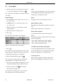
5.3
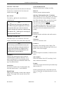
With MAC 1200 units equipped with the optional
Storage program
[ D rPur ci nk te n ] S e n d D e l e t e C h a n g e
Delete transmitted ECGs
Print directory
1
Id
Last Name, First Name
1 1 D w ye r, Pa t r i ck
10 Edison, Charles
9 Fa r m e r, E d
8 Fulham, Charlene
7 G a rd n e r, A l b e r t
6 Gilham, Roberta
5 Hanson, Dave
4 M i l l e r, C a r l a
3
3 Myers, Rod
2 Norton, Peter
1 Peterson, Barbara
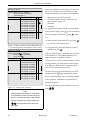
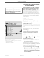
The Storage Program
Storage Program MEMO the ECG including patient,
measurement and analysis data can be saved with the
store/
retrieve
button after ECG acquisition. A message in-
forms the user that ECGs are being saved and indicates the number of stored ECGs.
To retrieve an ECG from memory, simultaneously
2
press
and
store/
retrieve
.
You will see the storage program as shown in Figure
5-2.
At the top, you will find the function keys:
Figure 5-2. Storage program
1 Function keys (the "Print" function is activated)
2 Selected patient files
3 Current cursor position
-
Print (prints the selected ECG)
Send (see section 5.5 "ECG Transmission")
Delete (deletes the selected ECG)
Change (enables modification of the patient data)
When you first call up the display, the Print function
is selected (1). The list below shows all patients for
whom ECG are stored.
Note
With a fully charged battery and the unit turned off,
ECGs will remain stored for approx. 4 weeks.
To perform an action with one or more ECGs, you
must first select the ECG(s).
•
To do so, move the cursor down with
.
When the cursor has reached "Print directory", it
moves on to the patient list. In the list, the bar cursor
changes to a line cursor (3, Figure 5-2).
•
To select multiple ECGs, select them with
, while holding
down. Selected ECGs are
marked with a black bar in the margin of the display (2). You can deselect the ECGs with the
same key combination.
227 492 04-F
MAC® 1200
29
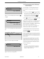
Recording in 12 Lead Mode
Storage program
[Print] Send Delete Change
Delete transmitted ECGs
Print directory
ECG taken
18.12.2000 09:56:35
18.12.2000 10:21:22
18.12.2000 11:22:56
18.12.2000 11:54:22
19.12.2000 08:22:56
19:12:2000 10:23:55
19.12.2000 11:01:25
19.12.2000 12:12:44
19.12.2000 15:55:12
19.12.2000 16:15:11
19.12.2000 17:33:18
Due to the limited size of the display, it is not possible to view the entire list at a time. These are the
columns that follow to the right of the patient name:
S Pati
(S)
(S)
(S) 1
(S)
- date and time of the ECG recording
- S (indicates that the ECG has been sent to another system, 1, Figure 5-3)
- patient ID
- comments
To display the remaining columns, you can continuously scroll the display with
list by the display's width with
or you can shift the
alt
and
(Figure
5-3).
•
When you have selected all ECGs, press the
key to return to the function keys.
Figure 5-3. Memory table of contents shifted to the left
1 (S) indicating ECGs transmitted to a host system
Storage program
Memory is full
[Print] Send Delete Change
Delete transmitted ECGs
Print directory
ECG taken
S
18.12.2000 09:56:35
18.12.2000 10:21:22
18.12.2000 11:22:56
18.12.2000 11:54:22
19.12.2000 08:22:56
19:12:2000 10:23:55
19.12.2000 11:01:25
19.12.2000 12:12:44
19.12.2000 15:55:12
19.12.2000 16:15:11
19.12.2000 17:33:18
•
Using the cursor, select the function you need
and initiate it with
Pati
.
With the "Print directory" command, you print a list
of all stored ECGs. The printout includes all columns, except the "Comments" column.
If you try to save an ECG when the memory is full, a
message informs you of the memory status (Figure
5-4). When you delete an ECG from memory, the
new ECG will automatically be saved.
The unit may be set up to automatically save ECGs
(without pressing
store/
retrieve
) and automatically remove
ECGs from memory that were successfully transmitted to CardioSys, CardioSoft or to the MUSE CV
Information System.
The storage program can be terminated at any time
Figure 5-4. "Memory full" message
with
.
Note
– When printing a large number of stored ECGs,
we recommend to connect the unit to the power
line or to check that the battery is fully charged.
– When you terminate the storage program with
, it is not possible to save the current
ECG again.
30
MAC® 1200
227 492 04-F
Recording in 12 Lead Mode
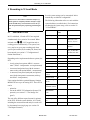
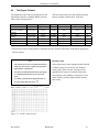
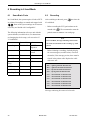
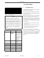
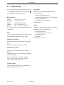
5.4
The Report Formats
The length and scope of the reports depends on the
implemented software (standard, MEAS (measurement), DIAG (interpretation)).
Format
4x2.5R1 (default
format)
4x2.5R3
2x5R1
2x5_50
1x10R12
1x10R3
ECG traces
length/leads
4x2.5s/4x3
Rhythm lead
length/leads
10 s/1
4x2.5 s/4x3
2x5 s/2x6
2x5 s/2x6
10 s/1x12
10 s/1x3
10 s/3
10 s/1
No
No
10 s/3
The table below shows all of the 6 different report
formats available with the MAC 1200 units.
Speed
Measurement*
Interpretation*
Pages
25 mm/s
Yes
Yes
1
25 mm/s
25 mm/s
50 mm/s
25 mm/s
25 mm/s
Yes
Yes
Yes
No
Yes
Yes
Yes
Yes
No
Yes
1
1
2
1
1
* measurement results and interpretative statements are only available from MAC 1200 with the appropriate
software options
Detailed results
Note
-
The printed reports are unconfirmed documents.
They must be overread, verified, and signed by a
physician for confirmation.
-
The heart rate HR annotated on the report pages
is calculated from all beats of the 10 second
ECG.
-
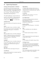
To obtain a printout of the full patient data, select the 6 Lead Mode and press copy .
University Hospital, Dr. Williams
GEMS IT
MAC 1200
John Doe
male, Caucasian, 32 years, 6.7 ft., 172 lb, 161/133 mmHg Pacemaker 414 355 378
HR
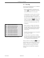
In the setup menu of units equipped with the MEAS
or DIAG option, you can choose the "Detailed
results" page. When selected, this page will be
appended to the reports. It contains patient data,
measurement results (MEAS), interpretative statements (DIAG), medians and the tabular measurement values.
101BPM
Feb.09.2001 11:07:22 AM 25mm/s 10mm/mV ADS 50Hz 0.08 - 150Hz 1x10R12 12 Lead 12SL V5.2
Figure 5-5. 1x10R12 report format
227 492 04-F
MAC® 1200
31
Recording in 12 Lead Mode
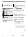
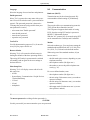
5.5
Note
Observe the safety information given in section 3.6
"Connecting External Devices".
Resting ECGs acquired in 12 Lead Mode can be
transferred to host systems (e.g. to the MUSE CV
Information System (version 004A or higher)). The
units can either communicate via modem or directly
via a connection cable (see section "Direct Transmission" below).
5.5.1 Transmission via Modem
Storage program
[ D rPur ci nk te n ] S e n d D e l e t e C h a n g e
Delete transmitted ECGs
Print directory
1
Id
Last Name, First Name
1 1 D w ye r, Pa t r i ck
10 Edison, Charles
9 Fa r m e r, E d
8 Fulham, Charlene
7 G a rd n e r, A l b e r t
6 Gilham, Roberta
5 Hanson, Dave
4 M i l l e r, C a r l a
3
3 Myers, Rod
2 Norton, Peter
1 Peterson, Barbara
ECG Transmission
Depending on the modem model used, the modem
must be connected either with the 9-pole cable
223 378 01 or with the 25-pole cable 223 378 02.
For transmission of the ECG, the unit must be set up
as described in section 9.9 "ECG Transmission via
Modem".
2
After acquisition of the ECG, the transmission is
initiated with
copy
(if "Manual copy" is set to "Host"
in the setup menu - see section 9.2 "12 Lead Mode").
The recorder is also capable of transmitting stored
ECGs (if MEMO option is installed). To retrieve
down while pressing
ECGs from memory, hold
store/
retrieve
Figure 5-6. Storage program
1 Function keys (the "Print" function is activated)
2 Selected patient files
3 Current cursor position
. You will see the storage program screen (Fig-
ure 5-6).
•
To select one or more ECGs for transfer, move
.
the cursor down with
When the cursor has reached "Print directory", it
moves on to the patient list. In the list, the bar cursor
changes to a line cursor (3, Figure 5-6).
•
To select multiple ECGs, select them with
, while holding
down. Selected ECGs are
marked with a black bar in the margin of the
display (2). You can deselect the ECGs with the
same key combination.
•
When you have selected all ECGs, press the
key to return to the function keys.
•
Using the cursor, select the “Send” command and
initiate the function with
32
MAC® 1200
.
227 492 04-F
Recording in 12 Lead Mode
You will see the transmission menu as shown in
Figure 5-7.
•
•
Figure 5-7. Transmission menu
•
Check the displayed telephone number and press
to initiate the transfer.
If it is necessary to change the number, press
to display the setup menu.
With
setup
, the transmission can be stopped.
As soon as you initiate the transmission with
,
the unit will automatically dial the number of the
modem at the receiving end and establish a connection (Figure 5-8). Then it will send the ECG (Figure
5-9).
After the transmission, a message on the display
Figure 5-8. Initializing the transmission
indicates the number of successfully transmitted
ECGs. As soon as you acknowledge the message
with
, the 12 Lead Mode acquisition screen
appears.
The system identifies ECGs that were successfully
sent to the host system with the letter "S" (1, Figure
5-3). All of these ECGs can be deleted with the
command "Delete transmitted ECGs".
Figure 5-9. Display during ECG transfer
If it is not possible to transmit the ECG (wrong
modem setup, modem off), the unit will display an
error message, such as "ECG Transmission Error!
(CSI)" (Figure 5-10).
In this situation you have the following choices:
− you can repeat the transmission with
− you can change the settings with
Figure 5-10. Error message
227 492 04-F
setup
− you can stop the transmission with
MAC® 1200
.
33
Recording in 12 Lead Mode
Modem Error Messages
Cause
ECG Transmission Error! (CSI)
The connection was interrupted due to a fault.
Check interface!
Fault in RS232 interface or modem. Modem may be
switched off.
No dial tone!
No dial tone detected.
Busy!
Busy signal detected.
No answer!
No answer at remote end.
No carrier!
Carrier signal lost or not detected.
Check modem configuration!
Modem configuration error.
34
MAC® 1200
227 492 04-F
Recording in 12 Lead Mode
5.5.2 Sending Data to a MUSE CV Information System via Modem
Note
Pacemaker information, telephone number and comments entered in the patient data are not transmitted to
the MUSE CV Information System.
Before sending data to the MUSE CV Information
System, the MAC 1200 automatically logs on to
MUSE. Then the data will be transmitted. If the
transmission is stopped, the MAC 1200 may take a
few seconds before canceling the connection because it has to log off the MUSE CV Information
System first. Then the communication link with the
receiving modem is interrupted and the standard
display reappears.
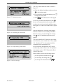
5.5.3 Direct Transmission
The unit must be connected to the PC or to the
MUSE CV Information System by means of the
connection cable 223 362 03.
Storage program
[ D rPur ci nk te n ] S e n d D e l e t e C h a n g e
Delete transmitted ECGs
Print directory
1
Id
Last Name, First Name
1 1 D w ye r, Pa t r i ck
10 Edison, Charles
9 Fa r m e r, E d
8 Fulham, Charlene
7 G a rd n e r, A l b e r t
6 Gilham, Roberta
5 Hanson, Dave
4 M i l l e r, C a r l a
3
3 Myers, Rod
2 Norton, Peter
1 Peterson, Barbara
For transmission of the ECG, the unit must be set up
as described in section 9.10 "Direct ECG Transmission".
After acquisition of the ECG, the transmission is
started with
2
copy
.
The MAC 1200 is also capable of transmitting
stored ECGs (if Memory option MEMO is installed).
Activate the storage program by simultaneously
pressing
and
store/
retrieve
(press the
button first and
hold it depressed) (Figure 5-11).
Figure 5-11. Storage program
1 Function keys (the "Print" function is activated)
2 Selected patient files
3 Current cursor position
•
To select one or more ECGs for transfer, move
the cursor down with
.
When the cursor has reached "Print directory", it
moves on to the patient list. In the list, the bar cursor
changes to a line cursor (3, Figure 5-11).
•
To select multiple ECGs, select them with
, while holding
down. Selected ECGs are
marked with a black bar in the margin of the
display (2). You can deselect the ECGs with the
same key combination.
227 492 04-F
MAC® 1200
35
Recording in 12 Lead Mode
•
When you have selected all ECGs, press the
key to return to the function keys.
•
Using the cursor, select the “Send” command and
initiate the function with
.
The transmission is first initialized (Figure 5-12),
then it starts (Figure 5-13).
Figure 5-12. Initializing the transmission
After the transmission, a message on the display
indicates the number of successfully transmitted
ECGs. As soon as you acknowledge the message
with
, the 12 Lead Mode acquisition screen
appears.
Figure 5-13. Display during ECG transfer
If it is not possible to transmit the ECG (wrong
modem setup, modem off), the unit will display an
error message, such as "ECG Transmission Error!
(CSI)" (Figure 5-14).
In this situation you have the following choices:
− you can repeat the transmission with
− you can change the settings with
setup
− you can stop the transmission with
.
5.5.4 Direct Transmission of Data to a
MUSE CV Information System
Figure 5-14. Error message
36
Before sending data to the MUSE CV Information
System, the MAC 1200 automatically logs on to the
MUSE CV Information System. Then the data will
be transmitted. If the transmission is stopped, the
MAC 1200 may take a few seconds before canceling
the connection because it has to log off the MUSE
CV Information System first. Then the standard
display reappears.
MAC® 1200
227 492 04-F
Recording in 12 Lead Mode
5.5.5 Receiving Data with the CSI Communication Protocol
(see also chapter 13 "Technical Specifications")
Initializing modem . . . .
Cancel : [ START / STOP]
Receiving ECGs is only possible in the 12Lead
Mode.
•
Use the key combination
and
copy
to display
the screen for receiving ECGs (Figure 5-15). The
connected modem is automatically initialized.
Figure 5-15. Screen display after activation of
and
The procedure can be aborted with
.
copy
•
Press
to enable the "receive data" mode. The
procedure can be aborted with
Modem initialized
Waiting for ECG data : [ ENTER ]
Cancel : [ START / STOP]
.
When you have enabled the "receive data" mode, the
standard screen display of the 12 Lead Mode displays. The message "12Lead/REC" indicates that the
unit is ready to receive data (Figure 5-17).
ECGs can be recorded in the 12 Lead Mode even
while the unit is in the "receive data" mode.
Figure 5-16. Screen display after modem initialization
A message displays on the screen when the unit is
receiving data (Figure 5-18). The reception can be
aborted with
12Lead/REC 60Hz ADS
4x2.5R1
10mm/mV
.
The ECG which has just been received is processed
for the printout. The report is printed in the selected
format. Multiple ECGs are received and printed one
after the other.
Standard
After printout of the last ECG, the "receive data"
mode is automatically disabled. The mode is also
disabled when you select another operating mode.
Figure 5-17. Unit is ready to receive data
The following information is annotated in the bottom line of each report:
Receiving ECG . . . .
– the sender
1
Cancel : [START / STOP]
– the software version and analysis program version used at the sending unit (e.g. ACQ-DEV:
M1200 V5.1M12i 12SL V13).
Figure 5-18. Unit is receiving ECG 1
227 492 04-F
MAC® 1200
37
Recording in 12 Lead Mode
5.5.6 Cart to Cart Communication
S0=1
auto answer after one ring
Via modem, ECG data can be transmitted between
two MAC 1200 units or between a MAC 1200 and
any ECG recorder using the CSI protocol (see sections 5.5.1 and 5.5.2).
V0
digit result codes selected (0 to 999)
5.5.7 Modem Setup (for Modem --> other)
Example of a dial string for a modem connected to a
branch (PBX system) and dialing a modem via the
public telephone network, using the touch tone
mode.
If you prefer to use another modem than the standard
models listed in the Communication menu
(MultiTech, Elsa), you will have to enter a few
parameters required for communication between the
MAC 1200 and the modem.
For the AT commands that your modem understands, please refer to the modem user instructions.
Three command sequences have to be entered in all,
each of which defines a specific modem operating
state:
init string: AT&FM1X3S0=1V0
2. AT Command for Establishing a Communication Link
AT
prefix that precedes every command
line
DT
touch tone dial mode
xxx
after DT, enter the characters for
access to the public telephone network (e.g. 0)
W
W, placed after a number, tells the
modem in a PBX system to wait for
the dial tone of an outside telephone
line
1. the modem is initialized (init string)
2. a communication link is established (dial string)
3. the communication is terminated (hangup string)
These three strings are entered in the modem setup
menu (see section 3.6 "Connecting External Devices").
The example below shows the command strings for
the MultiTech ZDX modem.
1. AT Command for Modem Initialization
AT
&F
prefix that precedes every command
line
fetch factory configuration (loads the
factory configuration from ROM into
the active configuration memory
(RAM))
M1
speaker is always on
X3
call progress signal monitoring
enabled
38
dial string: ATDTOW
3. AT Command for Termination of the Communication
The communication is terminated in two steps.
First of all, the MAC 1200 sends an escape command to return from the on-line state to the command state. Then the hangup command follows:
+++
escape command
AT
prefix that precedes every command
line
H
hangup command
hangup string: +++ATH
MAC® 1200
227 492 04-F
Recording in 12 Lead Mode
5.6
•
•
•
•
Brief Operating Instructions –
12 Lead Mode
Switch on the unit and wait for self-test to end
Apply electrodes to patient
Enter patient data -
pat
info
Check device settings
- report sequence
- report format
- AC filter
- override function
- 12SL interpretation configuration
•
•
•
•
Modify device settings, if required -
setup
Wait for patient to lie motionless and for the unit
to collect 10 seconds of ECG data
Check that no lead failure message is displayed
Start recording with
227 492 04-F
MAC® 1200
39
Recording in 6 Lead Mode
6 Recording in 6 Lead Mode
6.1
6.2
Some Basic Facts
Recording
6
In 6 Lead Mode, the system acquires 6 leads of ECG
After switching on the unit, press
in realtime. Recordings are started and stopped with
6 Lead Mode.
to select the
. Some of the system settings can be custom- Before recording the ECG, patient data can be
ized. They are labeled with "configurable".
entered with
pat
info
. We recommend to enter the
patient's name to annotate it on each page.
The following information refers to a unit with the
system defaults (see table below). For instructions
on changing the device setup, refer to section 9.3
"6 Lead Mode".
Note
In 6 Lead Mode, messages indicating disconnected
Parameter
System defaults Options
electrodes are annotated on the recording, e.g. Lead
Report Sequence
STANDARD
CABRERA,
SEQ.NO.4
fail V1.
Gain
10 mm/mV
"*auto", 5, 20, 40
mm/mV
− Before initiating a recording, check the display
for error messages (see table below). Check all
Speed
25 mm/s
5, 50 mm/s
electrodes; if the message persists, there must be
Muscle Filter
No
Yes
a break in the patient cable. Replace the cable
Muscle Filt.
Frequ.
40 Hz
20 Hz
AC Filter
Yes
No
Anti-Drift System No
Yes
*LA*: left arm electrode disconnected
Auto. Paper Feed
No
*LL*: left leg electrode disconnected
Yes
with a new one.
*RL*: right leg electrode disconnected
*RA*: right arm electrode disconnected
*V1*: chest electrode V1 disconnected
*V2*: chest electrode V2 disconnected
*V3*: chest electrode V3 disconnected
*V4*: chest electrode V4 disconnected
*V5*: chest electrode V5 disconnected
*V6*: chest electrode V6 disconnected
Messages indicating disconnected electrodes
40
MAC® 1200
227 492 04-F
Recording in 6 Lead Mode
− The recording is started and stopped with
Note
.
− Please note that filters may suppress diagnostically relevant portions of the signal, because they
limit the transmission range. Filters should
therefore only be enabled if necessary.
− Before and during the recording, the second set
of 6 leads can be selected with the
a
b
c
d
lead
key.
e
With the system defaults, the MAC 1200 will activate the following functions and settings:
− the standard report sequence: I, II, III, aVR, aVL,
aVF, V1, V2, V3, V4, V5, V6, also available:
CABRERA, SEQ. NR. 4 (custom report sequence)
− a gain of 10 mm/mV (configurable) (calibration
pulse at the beginning of the recording The unit
can be set up to automatically adapt the gain to
the ECG signal (see section 9.3 "6 Lead Mode").
Also, the gain setting can be changed with
gain
(5, 10, 20 and 40 mm/mV).
− the AC filter is enabled
− the muscle filter is disabled
− the anti-drift system (cubic spline) is disabled
(configurable)
− the writer prints at a speed of 25 mm/s, the speed
can be changed with
i
j
− Pressing
k
Figure 6-1. 6 Lead mode display
a Operating mode
b Muscle filter enabled
c AC filter enabled
d Anti-drift system enabled
e Patient name
f Writer speed
g Gain 10 mm/mV (automatic gain adjustment off)
h Report sequence
i Right leg electrode failure message
j Heart rate
k Heart rate limit (adjustable)
copy
format/
speed
will output the patient data after the
ECG recording.
− The unit advances the paper to the beginning of a
new page each time a recording is initiated (configurable)
All relevant device settings are shown on the display
(Figure 6-1).
− If you change the writer speed, lead group or any
filter settings during a recording, the unit will
briefly stop.
− With
lead
you advance to the next group of 6
leads of the selected report sequence.
227 492 04-F
MAC® 1200
41
Recording in 6 Lead Mode
− With
/
you toggle between the two lead
6.3
sets (3 each) on the display that belong to the recorded group.
− When the anti-drift system is enabled, there will
be a short delay before the recording starts. The
ECG will then be recorded with a delay of 2.2 s.
The heart rate limit is automatically calculated from
the date of birth (WHO 100% = 220 - age). When
•
•
Brief Operating Instructions –
6 Lead Mode
Switch on the unit and wait for self-test to end
Apply electrodes to patient
•
Select the 6 Lead Mode -
•
Enter patient data -
•
Check device settings
6
the date of birth is not entered, the unit will set the
- report sequence
limit at 180 bpm. This value can be changed with
- AC filter
and
( in steps of 5 bpm). The minimum
- ADS (cubic spline)
value for the heart rate limit is 30 bpm.
- heart rate alarm limits
•
•
•
42
pat
info
Modify device settings, if required -
setup
Watch ECG on display
Check that no lead failure message is displayed
•
Start recording with
•
Proceed to the next group of 6 leads with
•
Change the writer speed with
•
Switch on muscle filter with
•
Stop the recording with
•
Print patient data with
MAC® 1200
lead
format/
speed
muscle
filter
copy
227 492 04-F
Arrhythmia Mode
7 Arrhythmia Mode
7.1
GE marquette
MAC 1200
Some Basic Facts
John Doe
In Arrhythmia Mode, the MAC 1200 continuously
scans the ECG for arrhythmias.
From six simultaneously acquired leads, the MAC
1200 automatically selects the two that provide the
best signal for analysis.
Figure 7-1. Event recording
Note
After starting the program, press
format/
speed
to select a
continuous recording with a speed of 5 mm/s (configurable). If the unit identifies an arrhythmic event,
it will automatically switch to the fast paper speed.
With the same key
format/
speed
, the trend recording can be
stopped. The unit can be set up to automatically start
a trend recording when the Arrhythmia Mode is
initiated.
Parameter
System defaults Options
Report sequence
STD_C (chest
leads V1
through V6)
STD_RED (I, II,
III, V2, V4, V6)
STD_LI, (I, II, III,
aVR, aVL, aVF)
When the analysis algorithm detects an arrhythmia,
the event is recorded with "context" (Figure 7-1).
The length of the recording varies with the duration
of the event episode. In the setup menu (section 9.4
"Arrhythmia Mode") you determine the conditions
for a recording:
− the recorder starts each time it detects a singlebeat event - all
− the recorder starts each time it detects an event
different from the previous event - unequal
− the recorder does not start at all - no.
Some of the system settings can be customized.
They are labeled with "configurable". The following
information refers to a unit with the system defaults
(see table at left). For instructions on changing the
system setup, refer to section 9.4 "Arrhythmia
Mode".
CABR_LI (aVL, I,
-aVR, II, aVF, III)
HIGH_C (V1'
through V6')
Gain
10 mm/mV
"*auto", 5, 20, 40
mm/mV
Muscle Filter
No
Yes
Muscle Filt. Freq. 40 Hz
20 Hz
AC Filter
Yes
No
Trend Rec.
No
Yes
Arrhy Data
unequal
all, no
Episodes
chron.
prio, ventr., no
227 492 04-F
MAC® 1200
43
Arrhythmia Mode
7.2
Recording
− After switching on the unit, press
arrhy
to select
the Arrhythmia Mode.
*RL*: right leg electrode disconnected
*RA*: right arm electrode disconnected
− Before recording the ECG, patient data can be
*LA*: left arm electrode disconnected
pat
info
*LL*: left leg electrode disconnected
entered (
*V1*: chest electrode V1 disconnected
tient's name to annotate it on each page.
*V2*: chest electrode V2 disconnected
). We recommend to enter the pa-
− Before initiating a recording, check the display
for error messages (see table at left). Check all
electrodes; if the message persists, there must be
a break in the patient cable. Replace the cable
with a new one.
*V3*: chest electrode V3 disconnected
*V4*: chest electrode V4 disconnected
*V5*: chest electrode V5 disconnected
*V6*: chest electrode V6 disconnected
− The recording is started and stopped with the
Messages indicating disconnected electrodes
key.
Note
-
With
copy
, a single-page recording can be initi-
ated after program start.
-
Please note that filters may suppress diagnostically relevant portions of the signal, because they
limit the transmission range.
Filters should therefore only be enabled if necessary.
-
For proper functioning of the ECG analysis algorithm, pacemaker patients must be identified
in the patient data: Pacemaker – Yes (section 4.4
"Entering Patient Data").
Upon program start, the unit records 6 leads of ECG
(1 page). During the following learn phase, the
analysis algorithm learns the patient's typical QRS
complex. After the learn phase, the recorder prints a
report where the QRS complexes acquired in the
learn phase are labeled "L" and the complex found
to be the patient's typical complex is labeled
"QRSL". Having completed the learn phase, the
MAC 1200 is ready to identify arrhythmias.
With the system defaults, the MAC 1200 will activate the following functions and settings:
− the STD_C report sequence V1 through V6
(configurable)
− a gain of 10 mm/mV (configurable) (calibration
pulse at the beginning of the recording). The unit
can be set up to automatically adapt the gain to
the ECG signal (*auto)
− the AC filter is enabled (configurable)
− the muscle filter is disabled (configurable)
44
MAC® 1200
227 492 04-F
Arrhythmia Mode
a
b
c
d
− the anti-drift system is enabled
e
− the automatic baseline adjustment is enabled
− the slow trend recording is disabled (configurable)
− event episodes are recorded at a speed of
25 mm/s
− the unit documents all events that are different
from the previous event (configurable). You can
set up the unit to document all events or no event
at all.
All relevant device settings are shown on the display
(Figure 7-2).
The arrhythmia codes annotated on the recording are
explained in table 7-1 (next page).
The heart rate limit is automatically calculated from
j
k
l
the date of birth (WHO 100% = 220 - age). When
Figure 7-2. Arrhythmia mode display
a Operating mode
b Muscle filter enabled
c AC filter enabled
d Anti-drift system enabled
e Patient name
f Writer speed (event episodes)
g Slow trend recording enabled
h Gain
i Report sequence
j Right leg electrode failure message
k Heart rate
l Heart rate limit
the date of birth is not entered, the unit will set the
limit at 180 bpm. This value can be changed with
and
(in steps of 5 bpm). The minimum
value for the heart rate limit is 30 bpm.
Final Report
The arrhythmia recording can be stopped with
.
The final report can then be printed with
Note
The letter A on a recording indicates the presence of
artifact which does not allow the algorithm to identify arrhythmias. Causes include wandering base-
copy
. The
final report consists of
− the patient ID sheet (with all patient data as well
as with all analyzed QRS complexes, type and
number of detected events and the analysis duration in tabular form) and
− the episodes (3 sheets max. with 2 episodes
each).
lines. The anti-drift system largely prevents these
disturbances. Still you should check the electrodes
and leadwires.
227 492 04-F
MAC® 1200
45
Arrhythmia Mode
7.3
Brief Operating Instructions –
Arrhythmia Mode
asystole, limit value 4 s
ASYSTO
•
•
ventricular fibrillation/flutter
VFIB
•
Select the Arrhythmia Mode -
ventricular tachycardia (>3 PVCs)
VTAC
•
Enter patient data -
ventricular run (3 PVCs)
RUN
•
Check device settings
ventricular couplet (2 PVCs)
CPLT
- report sequence
pause of 2 missed beats
PAU2
- AC filter
pause of 1 missed beat
PAU1
- trend recordings
early PVC
EPVC
- episodes
ventricular bigeminy
VBIG
- heart rate alarm limits
new form (e.g. intermittent bundle
branch block)
NF
multiform PVCs
Arrhythmic Events
Switch on the unit and wait for self-test to end
Apply electrodes to patient
arrhy
pat
info
•
Modify device settings, if required -
MULT
•
Check that no lead failure message is displayed
supraventricular arrhythmia
SVAR
•
Start recording with
paroxysmal supraventricular tachycardia
PSVT
•
Switch on muscle filter with
TACH
•
Stop the recording with
tachycardia
bradycardia
BRAD
•
Print patient data with
pacemaker malfunction
PERR
ventricular escape beat
ESC
premature ventricular contraction
PVC
premature supraventricular contraction
PSVC
aberrant beat
ABR
pacemaker capture
PCAP
pause (>l.5 times the normal RR interval)
TL
absolute pause, limit value 3 s
PAUA
artifact
A
learn phase
L
learned QRS complex
QRSL
setup
muscle
filter
copy
Table 7-1. Arrhythmia codes
46
MAC® 1200
227 492 04-F
ECGs of Pacemaker Patients / ECG Recording During Defibrillation
8 ECGs of Pacemaker Patients / ECG Recording During Defibrillation
8.1
Recording ECGs of Pacemaker
Patients
8.2
Due to the slow paper speed it is not possible to
display pacer pulses directly on the ECG recording.
At a paper speed of 50 mm/s and a pulse duration of
0.5 ms, the width of the recorded pacer pulse would
be only 0.025 mm.
For this reason the recorder reduces the pulse amplitude and expands the pulse width, so that the pacer
pulse is easier to identify. The MAC 1200 records
the pulse with the correct polarity, with a width of 5
ms and with the same amplitude in all leads (depending on the polarity of the pacer pulse in leads I and
II, the pacer pulse in lead III may be suppressed).
The amplitude of the reverse current may differ from
lead to lead. Figure 8-1 shows an ECG recording
with pacer pulses.
ECG Recording During Defibrillation
The patient signal input is defibrillation-proof so it
is not necessary to remove the ECG electrodes
before defibrillating the patient. However, when
using stainless steel or silver electrodes, the defibrillator discharge current may cause complete polarization at the electrode/skin interface. This condition
may prevent ECG signal acquisition for several
minutes. With silver/silver chloride electrodes, this
will not happen.
Set the MAC 1200 to 6 Lead Mode when you may
have to defibrillate the patient while recording the
ECG, and disable the anti-drift system as this would
cause a 2 second signal delay (section 9.3 "6 Lead
Mode").
If electrodes made of other materials are used,
disconnect the patient cable from the recorder while
the shock is applied.
Warning
− Equipment Damage — For reasons of patient
safety, use only the original GE Medical Systems
Information Technologies patient cable. Before
connecting the cable to the device, check it for
signs of mechanical damage. Do not use a damaged cable.
Figure 8-1. ECG recording with pacer pulses
− Patient Hazard, Delayed ECG Display — Use silver/silver chloride electrodes for ECG signal acquisition, if the patient may have to be defibrillated.
Warning
Incorrect HR, No HR Alarm — If several adverse
conditions exist at once, the possibility that the pacer
pulses are interpreted (and counted) as QRS complexes should be considered. At the same time, however, QRS complexes might be suppressed in certain
situations. Therefore, pacemaker patients should
always be watched closely.
− Shock Hazard — The patient signal input of the
recorder is protected against damage resulting
from defibrillation shocks. Nevertheless, extreme
care should be exercised when defibrillators are
used on a patient connected to other devices
while a shock is released. During defibrillation,
do not touch the patient, the electrodes or the
leadwires.
Note
Observe the defibrillator safety information.
227 492 04-F
MAC® 1200
47
System Setup
9 System Setup
9.1
•
Some Basic Facts
setup
Press
9.2
•
to display the setup menu.
Report Sequence
[STANDARD] (I, II, III, aVR, aVL, aVF, V1, V2,
V3, V4, V5, V6)
CABRERA (aVL, I, -aVR, II, aVF, III, V1, V2, V3,
V4, V5, V6)
To access the menu options, position the bar
cursor on the option with the cursor keys and
Rhythm Leads
.
The operating steps to select a setting are always the
same:
•
Using the cursor keys
and
, you select the
option, then you confirm the selection with
.
Individual items can be skipped with
•
Press
Any three of the available ECG leads can be selected
as rhythm leads. They are printed with report formats 4x2.5R3 and 1x10R3. Formats 2x5R1 and
4x2.5R1 will show only the first of the rhythm leads.
Gain
The cursor will move to the next menu item.
•
.
The setup menu for automatic 12 lead recording will
appear.
The angular brackets [ ] identify the system
defaults.
At "Operating mode", you will always see the currently selected mode. So be sure to select the appropriate mode before entering the setup menu.
confirm the selection with
Use the cursor keys to position the bar cursor on
"12 Lead" and confirm the selection with
The setup menu with the following options will
appear:
− Operating mode: 12 Lead (6 Lead, Arrhythmia)
− General Settings
− Communication
− Patient Data Setup
− Option Code
•
12 Lead Mode
5, [10], 20, 40 mm/mV, *auto
or
.
Report Format
(
%
0
O
I
J
<
9
8
7
U
N
to exit the setup mode.
K
setup
P
)
L
X
>
M
For an overview of the available report formats,
refer to section 5.4 "The Report Formats". The
default format is 4x2.5R1.
12
format/
speed
copy
muscle
filter
lead
gain
store/
retrieve
6
arrhy
start
pat
info
stop
standby
Detailed Results
The "Detailed results" page will be printed,
Yes/[No] (section 5.4 "The Report Formats", only
available with option MEAS or DIAG).
battery low
Muscle Filter/AC Filter
24
8
9
Figure 9-1. System setup keys
48
19
Elimination of muscle artifact and AC line interference.
Default: muscle filter [No], AC filter [Yes]
MAC® 1200
227 492 04-F
System Setup
Configuration of the 12SL Interpretation
Note
Please note that filters may suppress diagnostically
Use Screening criteria
relevant portions of the signal, because they limit the
The screening criteria can be enabled or disabled.
Default: [disabled]
transmission range. Filters should therefore only be
enabled if necessary.
Suppress NORMAL Statement
If you select 'Yes', the interpretation statement
"normal ECG" will not be shown.
Muscle Filter Frequency
Cut-off frequency of the muscle filter ([40 Hz],
20 Hz).
The frequency range is indicated in the lower margin
of the recording strip.
"0.08 - 40 Hz" (40-Hz muscle filter enabled)
"0.08 - 20 Hz" (20-Hz muscle filter enabled)
"0.08 - 150 Hz" (muscle filter off).
Manual copy to
When the
copy
Suppress ABNORMAL Statement
If you select 'Yes', the interpretation statement
"abnormal ECG" will not be shown.
Interpretation
Default: [Yes]. If you select 'No', 12 SL interpretation results will not be generated nor shown.
Print Interpretation
key is pressed, the unit will print a
copy of the ECG [EKG] or send the ECG to a HOST
system (MUSE CV Information System).
No. of copies
If you do not want to print the ECG, but only collect
data, select "0" (message on display "REC OFF").
When a number greater than 1 is selected, multiple
copies of the reports will be printed. Default: [1]
Autosave ECG (only with MEMO option)
After report generation, the ECG will or will not be
automatically saved to the internal memory (Yes,
[No]).
Delete ECG after Transmission
(only with MEMO option)
Only available if "Interpretation" is set to "Yes".
Default: [Yes]. The interpretative statements are
printed on the reports. When you select "No", the
interpretation will not be printed, but it can be sent
to the MUSE CV Information System.
Override Function
When this function is enabled [Yes], the recorder
will print in 12 Lead Mode, even when not all electrodes are applied or do not supply a good signal.
When electrodes are disconnected, a message informing the user of poor signal quality will be
printed on the recording.
Furthermore, systems with interpretation capability
will print a message indicating that the measurement
results and interpretation may be incorrect.
ECGs that were successfully sent to a host system
via the RS232 interface will be cleared from the
recorder memory (Yes, [No]).
If this menu item is set to "Yes" and ECGs have
already been sent from the recorder memory, these
ECGs will be deleted after the next transmission of a
stored ECG.
227 492 04-F
MAC® 1200
49
System Setup
9.3
•
6 Lead Mode
Use the cursor keys to position the bar cursor on
Gain
"6 Lead" and confirm the selection with
The setup menu for continuous recording of 6 leads
will appear.
*auto, 5, [10], 20, 40 mm/mV; with "*auto", the unit
will automatically determine the appropriate gain
setting for the 6 simultaneous leads.
Report Sequence
Speed
1. [STANDARD] (l, II, III, aVR, aVL, aVF, VI, V2,
V3, V4, V5, V6)
Changes the writer speed. Default: [25 mm/s]
2. CABRERA (aVL, l, -aVR, II, aVF, III, VI, V2,
V3, V4, V5, V6)
Muscle Filter/AC Filter
.
3. SEQ. NO. 4 (here, users can define a custom
report sequence):
•
•
Position the cursor on "SEQ. NO. 4".
Press
setup
Elimination of muscle artifact and AC line interference
Default: muscle filter [No], AC filter [Yes]
Muscle Filter frequency
.
Cut-off frequency of the muscle filter ([40 Hz],
20 Hz).
The frequency range is indicated in the lower margin
of the recording strip.
"0.08 - 40 Hz" (40-Hz muscle filter enabled)
"0.08 - 20 Hz" (20-Hz muscle filter enabled)
"0.08 - 150 Hz" (muscle filter off).
The display shown in Figure 9-2 will appear.
Figure 9-2. Creating a custom report sequence
Anti-Drift System (ADS) (cubic spline)
•
Press
.
The cursor will move to the position for entry of the
lead in channel 1. Follow these steps, if you wish to
record lead aVR in channel 1, for instance:
•
Auto. Paper Feed
Enter AVR and confirm the entry with
.
The cursor moves to the position for entry of the
lead designation. AVR appears there as well.
•
•
In case of wandering baselines, the anti-drift system
restores the baseline to its original position (signal
delay with ADS approx. 2 s). Default: [No]
Before each recording, the recorder advances the
paper to the beginning of a new page ([Yes], No).
If you wish to enter another designation, you can
overwrite the default name (4 characters max.).
Confirm your entry with
and repeat the
above steps for channel 2, etc.
You can write over "SEQ. NO. 4" if you wish to
enter another name for the report sequence.
50
MAC® 1200
227 492 04-F
System Setup
9.4
•
Arrhythmia Mode
Arrhy Data
Use the cursor keys to position the bar cursor on
"Arrhythmia" and confirm the selection with
.
The arrhythmia mode menu will appear.
Report Sequence
[STD_C]:
V1, V2, V3, V4, V5, V6
STD_RED:
I, II, III, V2, V4, V6
STD_LI:
I, II, III, aVR, aVL, aVF
CABR_LI:
aVL, I, -aVR, II, aVF, III
HIGH_C:
V1’, V2’, V3’, V4’, V5’, V6’
(C = chest leads, RED = reduced number of leads, LI
= limb leads)
Gain
*auto, 5, [10], 20, 40 mm/mV; with "*auto", the unit
will automatically determine the gain setting.
The recorder will document arrhythmias in the
following situations:
- each time an arrhythmia occurs
- each time an arrhythmia occurs that is different
from the preceding event
- arrhythmias are not documented
all, [unequal], no.
Episodes
Final report includes episode report, with episodes
listed by one of the following criteria
- in chronological order
- according to priorities (see table 7-1)
- ventricular beats only
- no episodes
[chron.], prio., ventr., no
Muscle Filter/AC Filter
Elimination of muscle artifact and AC line interference
Default: muscle filter [No], AC filter [Yes]
Muscle Filter Frequency
Cut-off frequency of the muscle filter ([40 Hz],
20 Hz).
The frequency range is indicated in the lower margin
of the recording strip.
"0.08 - 40 Hz" (40-Hz muscle filter enabled)
"0.08 - 20 Hz" (20-Hz muscle filter enabled)
"0.08 -100 Hz" (muscle filter off).
Trend Recording
The slow trend recording of 5 mm/s automatically
begins at program start ( [No]/Yes).
227 492 04-F
MAC® 1200
51
System Setup
9.5
System Setup Parameters
Ordering / Referring Physician / Technician
High HR beep
In the field at left, you see the last name of the
physician or technician selected as the default name.
When selecting "other", a menu displays where you
can enter up to 10 names (3-digit ID number, first
name, last name). The default name (and ID) is
automatically selected at power-up.
An audible signal sounds when the heart rate exceeds a limit value (Yes/[No]) (only in 6 Lead and
Arrhythmia Modes). The limit value (220 - age) can
be changed manually.
The "Referring Physician" is only relevant if you
send ECGs to the MUSE CV Information System.
This name will not be annotated on the ECG recording. Press the
key to exit the menu.
Institution Name
The name entered here will be printed on each report
page.
Cart #
Lead Labels
[AAMI] codes: RA, LA, RL, LL, V1 to V6 or
IEC codes: R, L, F, N, C1 to C6
Pace Enhancement
Pacer pulses are displayed enhanced and with a
given amplitude ([Yes], No).
When programming pacemakers, we recommend to
disable the pace enhancement.
Baseline roll filter
Select the lower cut-off frequency: = 0.04, [0.08],
0.16 Hz.
Enter any number between 1 and 9999 to identify
the cart (local system). The cart # entered here is the
default number that appears in "Patient Data".
Default: [1]
Date
Format: [month/day/year] or day.month.year
Site #
Time format [12] hours (am/pm) or 24 hours
Enter any number between 1 and 255 to identify the
MUSE CV Information System to which the ECGs
will be sent. The site # entered here is the default
number that appears in "Patient Data".
Default: [1]
Location #
Time
Units
Units of measurement for the patient's height and
weight: [in/lb] or cm/kg
Mains
AC line frequency (USA [60 Hz], Europe 50 Hz)
Enter any number between 1 and 600 to identify the
location of the sending system. The location # entered here is the default number that appears in
"Patient Data".
Default: [1]
Date/Time
LCD light off after
If operating controls are not activated within the
selected period of time the display backlighting
automatically switches off (system default [5 min],
adjustment range l to 99 min).
Enter date and time (enter 4 digits for the year).
Default Mode
Lead fail beep
This is the operating mode the unit defaults to after
power-up: [12 Lead], 6 Lead, Arrhythmia
Indicates when electrodes are not properly applied or
disconnected (Yes/[No]).
52
MAC® 1200
227 492 04-F
System Setup
9.6
Language
Select the language for user interface and printouts.
Enable password
Select "Yes" to protect the setup menu with a password. You will be asked to enter a password and to
repeat it. The password protection is then active.
To change the password (only possible when password protection is active)
−
−
−
−
select menu item "Enable password"
enter the old password
enter the new password
repeat the new password
Communication
Baud rate (HOST)
Transmission rate for the selected protocol. We
recommend the default setting of [19200 baud].
Protocol
The recorder offers two communication protocols:
"CSI" (Client Server Interface) and A5.
The CSI protocol supports the transfer of resting
ECGs from the resting ECG analysis system to a
MUSE CV Information System.
With the "A5" protocol, the 10-second resting ECG
can be transmitted to CardioSys and CardioSoft.
Test DATA
Modem
Used for demonstration purposes (Yes). It must be
set to [No] for proper clinical use.
Select the modem type. You can choose among the
standard modems MultiTech (MT 19.2, 56k), Elsa
14.4, 28.8, 33.6, 56k and a user-defined modem.
Restore defaults
Selecting "Yes" will restore the default setup (including the defaults of the three operating modes).
The resting ECG analysis system must be switched
off (standby) and on again for the new settings to
become effective.
Print Setup Lists
Selecting "Yes" will display a menu with all available setup lists.
− all lists
− System Setup / Communication / Periph. Devices
/ Patient Data Setup
− 12 Lead
− 6 Lead
− Arrhythmia
When using one of the standard modems, all you
have to enter is
− the dial mode (pulse or tone, depending on your
telephone network)
− the telephone number (28 digits max.)
− the number to access the public telephone network (e.g. "0").
For a user-defined modem, enter
− the telephone number (28 digits max.)
− the init string (20 characters max.) (see modem
operator's manual)
− the dial string (20 characters max.) (see modem
operator's manual)
− the hangup mode (20 characters max.) (see modem operator's manual)
✂--------------------------------------------------------------------------------------------------------------------------------------The master password overriding all other passwords is
SYSTEM
Use this password if you cannot remember your own password.
227 492 04-F
MAC® 1200
53
System Setup
9.7
Configuration of Patient Data Menu
The patient data menu can be set up to meet individual requirements. If you do not want to enter blood
pressure readings, for instance, you can remove the
corresponding prompts:
•
Use the cursor keys to position the bar cursor on
"Setup Patient Data" and confirm the selection
with
.
Select "No" for prompts that you want to remove
from the dialog.
Items
- Last name
- First name
- Date of birth
- Patient ID
−
−
−
−
ID required
Secondary ID required
Last name required
First name required
Fields on patient data entry screens that require an
entry, are identified with pointed brackets (e.g. Last
name: >............<).
Prompt 1 to 4
cannot be removed.
Items
If, for one of the data fields
you choose "Yes", an ECG can be recorded in 12
Lead Mode only if the corresponding patient data is
entered.
The patient data setup menu will appear.
•
"Required" Data Fields
- Height
- Weight
- Diastolic BP
- Systolic BP
- Referring Physician
- Medication
- Comments
- ID required
- Secondary ID
- Secondary ID required
- Last name required
- First name required
- Extra Questions
(Prompt 1 through Prompt 4)
are disabled. They can be enabled from the patient
data setup menu.
You can enter any text here (10 characters max.).
When you have entered the text, you can select the
format of the response field. There is a choice of 3
formats:
− alphanumeric field (17 characters max.)
− only numbers (9 numbers max.)
− Yes or No
•
To exit the menu, press
.
The patient ID length is selectable from 3 to 16
characters.
54
MAC® 1200
227 492 04-F
System Setup
9.8
Option Code
9.9
In this menu you enter the option codes to enable a
number of optional software functions. The respective option becomes active after you have entered
the code number. The code numbers are listed on the
option code sheet supplied with the different software options.
•
The option code menu appears. There is a choice of
6 options:
MEAS: measurement of the 10-second resting
ECG
DIAG: measurement and interpretation of the 10second resting ECG
MEMO: program for storage of up to 40 resting
ECGs
C100: activates the three options MEAS, DIAG,
MEMO for a maximum of 100 ECGs
C500: activates the three options MEAS, DIAG,
MEMO for a maximum of 500 ECGs
EVAL: activates the three options MEAS, DIAG,
MEMO for a maximum of 4 weeks
•
Press
setup
.
to display the setup menu for the 12
Lead Mode.
•
Use the cursor keys to position the bar cursor on
tion with
([HOST]).
•
Press
to clear the setup menu.
•
Use the cursor keys to position the bar cursor on
"Communication" and confirm the selection with
.
Selecting the Communication Protocol
•
•
•
Choose the modem you use from the list and
confirm the selection with
.
If your modem is not included in the list, select
"other" and enter the required modem commands
(see also "Modem Setup" in section 5.7).
.
The unit will accept the entered number only if it
corresponds to the unit's serial number. The serial
number is indicated at the top of the menu (Ser.No.
= xxxxxxxxx). This number must be the same as
printed on the nameplate (back of the device).
When you enter the code number for DIAG and
MEMO, the fields for C100, C500 and EVAL will
disappear.
227 492 04-F
Use the cursor keys to position the bar cursor on
.
Enter the 12-digit code number from the key-
Exit the menu with
Using the cursor keys, position the bar cursor on
"Protocol". Select the protocol CSI to send data
to a MUSE CV Information System, or select A5
if you will send data to CardioSys/CardioSoft.
"Modem, other" and confirm the selection with
Position the bar cursor on the option you wish to
activate.
board and confirm the entry with
•
Select the 12 Lead Mode and press
"Manual copy to HOST" and confirm the selec-
.
•
•
In the setup menu, position the bar cursor on
"Option Code" and confirm the selection with
•
ECG Transmission via Modem
•
•
When you have selected a standard modem, position the bar cursor on "Dial mode" and select the
appropriate mode.
Enter the telephone number of the receiving
modem and the number to access the public telephone network and terminate the setup with
.
.
MAC® 1200
55
System Setup
9.10 Direct ECG Transmission
•
Select the 12 Lead Mode and press
•
Press
setup
.
to display the setup menu for the 12
Lead Mode.
•
Use the cursor keys to position the bar cursor on
"Manual copy to HOST" and confirm the selection with
([HOST]).
•
Press
to clear the setup menu.
•
Use the cursor keys to position the bar cursor on
"Communication" and confirm the selection with
.
•
Select the same baud rate as at the receiving
device (2400, 4800, 9600, 19200, 38400, 57600).
Selecting the Communication Protocol
•
•
Using the cursor keys, position the bar cursor on
"Protocol".
Select the protocol CSI to send data to a MUSE
CV Information System, or select A5 if you will
send data to CardioSys/CardioSoft.
Use the cursor keys to position the bar cursor on
"Modem, none" and confirm the selection with
.
56
MAC® 1200
227 492 04-F
Loading Chart Paper
10 Loading Chart Paper
setu
•
•
p
0
P
9
O
8
I
on
off
)
>
M
<
N
.
B
,
V
K
%
J
*
H
+
/
C
:
X
;
Z
G
-
F
=
D
?
S
!
A
L
(
7
U
6
Y
5
T
4
R
3
E
2
W
1
Q
X
alt
Switch on the recorder.
Pull up the handle of the paper door and fold it
out (Figure 10-1).
1200
MAC
•
Remove the cardboard backing of the previous
paper pad.
Figure 10-1. Opening the paper compartment door
•
fo
p
setu
0
P
9
O
8
I
4
R
3
E
2
W
1
Q
MAC
+
>
M
<
N
.
B
,
V
/
C
:
X
;
Z
G
-
F
=
D
?
S
!
A
on
off
X
)
K
%
J
*
H
L
(
7
U
6
Y
5
T
stan
alt
1200
Figure 10-2. Inserting the new Z-fold pad
•
Remove the cardboard from the top of the new
pad and place the pad, including the cardboard
backing at the bottom and with the arrow pointing towards the unit, into the paper compartment
(Figure 10-2).
Pull the top sheet out of the compartment and
guide it around the guide roller (Figure 10-3).
12
y
6
cop
at/
form ed
spe
I
U
6
4
3
2
1
Q
W
!
A
on
off
MAC
E
?
S
;
Z
R
+
G
-
F
=
D
/
C
:
X
p
sto
>
M
<
ry low
N
.
B
,
V
rt
sta
pat
info
K
J
*
H
e/
stor eve
retri
gain
X
)
L
(
%
Y
5
T
y
arrh
lead
cler
mus
filte
p
setu
0
P
9
O
8
7
batte
dby
stan
alt
1200
Figure 10-3. Guiding the leading paper edge over
the guide roller
•
Holding the leading edge of the paper in place
between the two markers on the recorder, close
the paper door (Figure 10-4). Ensure that it locks
into place on both sides.
12
y
6
cop
at/
form ed
spe
I
6
5
4
3
2
1
Q
W
!
A
on
off
MAC
E
?
S
;
Z
R
=
D
:
X
T
-
F
/
C
U
Y
*
+
G
,
V
H
.
B
%
y
arrh
e/
stor eve
retri
rt
sta
p
gain
X
sto
pat
info
)
L
(
J
lead
cler
mus
filte
p
setu
0
P
9
O
8
7
K
>
<
M
ry low
N
When inserting an already started Z-fold pad, the
grid side must face up and the first fold must point
towards the paper compartment.
batte
dby
stan
alt
1200
Figure 10-4. Closing the paper compartment door
227 492 04-F
MAC® 1200
57
Loading Chart Paper
End-of-Paper Indication
A stripe marks the last 10 pages of the Z-fold pad.
Note
When the writer runs out of paper during a re-
− Having inserted a new paper pad, be sure to acknowledge the "end of paper" message with
not with
cording, it will emit an audio signal and displays the
,
message "End of paper or paper jam, if OK, press
.
".
− When closing the paper door, take care that it
locks into place on both sides.
•
− There is a window in the paper door that allows
you to look inside the compartment and check
the paper supply.
− Use only the original CONTRAST® chart paper
or the GE Medical Systems Information Technologies thermal paper with queue marks or
holes. This paper has a special coating that prevents
- contamination and debris collecting on the
printhead and
- electrostatic build up.
- Furthermore, the thermosensitive layer and the
printhead characteristics are exactly matched.
Using other paper may result in recordings of
poor quality.
Moreover, the printhead may wear out prematurely. Use of other paper voids the warranty.
message with
.
Aging Stability
The standard ECG writer paper CONTRAST is
designed to guarantee full contrast for a period
between 1 and 5 years if it is handled as described
below before and after recording:
•
•
•
•
•
58
Insert a new paper pad and acknowledge the
MAC® 1200
Avoid continued, direct exposure of the paper to
− sunlight and other UV radiation,
− fluorescent light.
Store the paper in suitable rooms at a temperature
between 64 and 77 °F and a relative humidity between 40 % and 60 %.
Avoid direct contact of the paper with
− carbon and carbonless forms
− chart papers and adhesives containing tributyl
phosphate, dibutyl phthalate, or any other organic solvents
− document protectors, envelopes, and sheet
separators containing plasticizers.
Caution: The above components may also be
found in recycled papers.
− solvents or solvent-based products containing
alcohols, ketones, esters, or other substances
from this chemical group.
We recommend archiving ECG recordings on our
ECG filing cards only (P/N 217 043 03).
If longer storage periods are required, we suggest
using our ARCHIVIST chart paper (image legibility up to 15 years) or other image storage technologies.
227 492 04-F
Cleaning, Disinfection and Maintenance
11 Cleaning, Disinfection and Maintenance
11.1 Cleaning and Disinfecting the Recorder Housing
Warning
Before cleaning or disinfecting the device, disconnect it from the power line.
•
•
Clean the recorder housing with a moist cloth. Do
not let liquid enter the device. All cleaning agents
and disinfectants that contain alcohol and are
commonly used in hospitals are suitable, but do
not use disinfectants on a phenol base or peroxide
compounds.
Disconnect the cable from the recorder before
cleaning or disinfecting it. When disconnecting
the cable, be sure to pull on the connector, not on
the cable.
Clean the cable by rubbing it down with a cloth
moistened with soap water. Use a disinfectant for
disinfection. Do not immerse the cable in liquid.
227 492 04-F
In addition to the information given in this manual,
observe the instructions for use of the respective
electrode types.
•
11.2 Cleaning and Disinfecting the Patient Cable
•
11.3 Cleaning and Disinfecting the Electrodes
•
•
•
•
•
MAC® 1200
Discard disposable adhesive electrodes immediately after use to prevent that they are reused.
Clean reusable electrodes immediately after
removing them from the patient.
Peel off the adhesive foil before cleaning the
electrodes (rests of the adhesive can be removed
with benzine).
Then use warm water and a small brush to clean
the electrodes of cream or gel. Do not use pointed
or sharp objects for cleaning.
Disinfect the electrodes with alcohol-free disinfectant. Ensure that connectors and sockets do
not become wet.
The only approved sterilization method is gas
sterilization.
Frequently sterilizing the electrodes with ethylene oxide gas reduces the life of the plastic material.
59
Cleaning, Disinfection and Maintenance
11.4 Maintenance
Checks before each use
Technical Inspections
Before each use, visually inspect the device, the
leads and electrodes for signs of mechanical damage.
For safety, the devices require regular maintenance.
To ensure functional and operational safety of the
MAC 1200 units, Technical Inspections should be
carried out on an annual basis.
If you detect damages or impaired functions that
may adversely affect the safety of the patient or user,
do not use the device before it has been repaired.
These checks should be performed by persons with
adequate training and experience.
The checks can be carried out by GE Medical Systems Information Technologies within the framework of a service contract. The inspections include
the following checks:
•
•
•
•
Visually inspect the device and the accessories
for signs of mechanical damage that may impair
the device functions.
Check that the device labeling relevant for safety
is legible.
Run a performance test as described in the operator's manual.
Measure the resistance of the protective earth
conductor and the equivalent leakage current per
your national regulations.
The device does not require any other maintenance.
Disposal at the End of Its Service Life
Note
At the end of their service life, the device described
in this manual and its accessories must be disposed
of in compliance with the applicable local waste
control regulations. If you have questions regarding
the disposal of the product or of accessories, please
contact GE Medical Systems Information Technologies or its representatives.
60
MAC® 1200
227 492 04-F
Troubleshooting
12 Troubleshooting
Symptom
Cause
Remedy
Periodic superimposition of AC interference from the power line
line interference (60 Hz) (Figure
12-1)
Superimposition of irregular AC Muscle artifact caused by
line interference (Figure 12-2)
patient movements, hiccup,
coughing
Ground bed, verify position of the
leadwires, switch on AC filter
The printed date and time are
incorrect
Built-in lithium battery is
depleted. The battery has a life
of approx. 5 years
Notify service to check and/or replace
battery
The green standby indicator 23
does not light up, although the
recorder is connected to the
power line
Defective AC power adapter or
fuse
Notify service to check and/or replace
fuse
The patient should be warm enough
and resting comfortably (place cushions under arms and knees).
Comfort patient or distract patient's
attention, enable muscle filter (20 Hz /
40 Hz), if necessary.
The recorder does not write over Paper compartment not properly Paper door must lock into place on
the entire paper width
closed
both sides
In 12 Lead Mode, the recorder
does not stop and continues to
feed paper. This does not happen in 6 Lead Mode.
The paper pad was inserted the
wrong way round so the recorder cannot detect the cue
mark
Insert the paper pad as instructed
Unit operated on battery power: Connect recorder to the power line.
battery discharged
After a few minutes, the recorder is
activation of the
key, or
able to resume operation. Always
connect recorder to the power line
the recording is aborted.
when the battery low indicator 22
lights up. The battery capacity depends
on age, temperature and charge level
(chapter 3 "Putting the Device into
Operation").
Recorder does not start after
No recording in 12 Lead Mode
Failure of at least one electrode
Paper jam
Check all electrodes or enable Override
function (section 9.2 "12 Lead Mode").
Open paper compartment and removed
jammed sheet,
place beginning of paper between the
marks, close paper compartment and
press
227 492 04-F
MAC® 1200
.
61
Troubleshooting
Figure 12-1. Regular AC line interference
Note
In the presence of very strong AC line interference
in all leads, the thermal printhead may interrupt
the recording. Activate the AC filter (60 Hz) in
these situations.
Figure 12-2. Irregular AC interference
62
MAC® 1200
227 492 04-F
Technical Specifications
13 Technical Specifications
Recording
Paper feed
Direct recording of waveforms and alphanumeric
characters with rectangular coordinates by means
of thermal-array printhead printing on thermosensitive paper.
•
•
•
•
•
•
•
•
3 or 6 recording channels, or 12 in 12 Lead
Mode, overlapping
baseline pitch
6 channels: 31 mm (6 Lead)
12 channels: 16 mm (12 Lead.)
At paper end, the recorder emits an audio signal
and stops recording
the last pages of the pad bear a colored stripe in
the lower margin
Membrane keypad
writing width 200 mm max.
annotation of recorder settings, date, time and
entered patient name in the margin of the recording strip
with appropriate software, documentation of
analysis results in the respective operating
mode
Pushbuttons with tactile feedback
•
•
function keys for all routine operations
alphanumeric keyboard for entry of text
Display
graphics display with 24 x 40 characters, contrast
adjustment
resolution of the recording:
vertical
8 dots/mm
horizontal 25 µm at 25 mm/s
resolution of 320 x 240 pixels with display backlighting
Printer paper
Indicators (LEDs)
CONTRAST® Z-fold pad , 150 pages per pad,
equivalent to a chart length of approx. 45 m
paper width:
8.5 in.
sheet length:
11 in.
For mains power, battery status and start/stop
function
Automatic functions
To prevent damage to the printhead use only the
original CONTRAST® paper or the GE Medical
Systems Information Technologies thermal paper
with queue holes or marks.
227 492 04-F
paper speed
5-25-50 mm/s, key selectable
error limits at 25 and 50 mm/s, typ. ±l%
at 5 mm/s, ±10% max.
MAC® 1200
They assist and facilitate operation by
•
•
•
•
automatic control of lead selection, paper feed,
calibration (configurable)
report formatting (configurable)
automatic baseline adjustment
anti-drift system (cubic spline) compensating
for polarization voltage fluctuations (configurable)
63
Technical Specifications
Detection of pacer pulses
•
•
•
in single-fault condition (e.g. patient in contact
with line voltage) < 20 µA
pulse length between 0.1 and 2.5 ms
pacer pulse marker independent of pulse polarity
•
pulse amplitude between ± 5 mV and ± 700 mV
•
Heart rate indication
derivation of the heart rate from all ECG signals
•
•
display range between 30 and 300 bpm
display update with every heart beat, maximum
every 2 seconds
Signal inputs
•
non-destructive range for lead-electrode connections and the neutral electrode connection
referred to neutral electrode ±50 V, referred to
chassis ±1500 V
pulse voltage resistance of all lead electrode
connections and of the neutral electrode connection referred to chassis (either polarity, e.g.
defibrillation) 5000 V
monitoring of each electrode for open leads:
RA, LA, LL, RL, V1, V2, V3, V4, V5, V6
audio signal at printer start
Data interface
isolated patient signal input, IEC type CF, highvoltage protection for all lead connections and
neutral electrode, interference compensation via
neutral electrode, monitoring for open leads
one serial RS232 interface for exchange of data
with suitable external devices and software handshake
RS232 interface (standard V.24 interface):
•
•
•
•
•
•
•
64
electrode connections for RA, LA, LL, LA, Vl
to V6
input impedance for differential signals between any two electrode connections > 10 MΩ
at 10 Hz
input impedance for common-mode signals
referred to neutral electrode > 50 MΩ up to
60 Hz
•
•
•
input voltage range. ± 15V max.
output voltage range ±5 V min.
interface protected from electrostatic discharge
for ±10 kV max.
Transfer of ECGs with the CSI protocol between the MAC 1200 and the following units
dynamic range for differential signals between
any two electrode connections for AC voltage
±10 mV, for superimposed DC voltage (polarization voltage) ±600 mV
dynamic range for common-mode signals
referred to neutral electrode ±l V, referred to
chassis 263 V AC (rms)
quiescent input current via any electrode connection for l kΩ termination referred to neutral
electrode < 50 nA
patient leakage current (rms values) according
to IEC, class CF: in normal condition < 10 µA,
MAC® 1200
MUSE CVIS
MAC 5000
MAC VU
MAC 1200
SW version 004A and later
SW version 001B and later
SW version 002A and later
SW version V5.01 and later
Receiving data with the CSI communication
protocol from the following units
CardioSmart
SW version V4.21 and later
CardioSmart ST SW version V4.21 and later
Sending ECGs to the following units with the
A5 protocol
CardioSys / CardioSoft SW version V1.0 and later
227 492 04-F
Technical Specifications
•
Pin assignment of data port
5
2
3
•
2 RXDE
3 TXDE
5 circuit reference
•
6 modem supply
8
6
8 remote start
•
Remote start (hardware)
Paper feed via remote control connection (depending on selected operating mode). External make
contact referred to chassis via circuit reference:
•
•
•
•
source impedance Ri < 300 Ω
non-destructive load ± 10 V
•
ESD interface protection up to ± 10 kV
•
Patient input to recording
After lead formation and digitization simultaneous
transmission of all electrode signals to the digital
processing system; muscle filter, AC filter, pacing
pulse identification, automatic or manual sensitivity adjustment, automatic baseline adjustment and
drift compensation by means of the anti-drift
system (A.D.S.) can be enabled or disabled simultaneously for all channels; digital output of processed signals via thermal-array printhead.
•
•
•
•
•
contact dwell > 100 ms
Signal transmission
•
•
low cut-off frequency (-3 db limits) 0.08 Hz,
equivalent to a time constant of 2.04 s
high cut-off frequency (3 dB limits) operating
mode: 12 Lead, 6 Lead 150 Hz (IEC/AHA) operating mode: Arrhy 100 Hz (IEC)
for all leads, gain adjustment in four steps:
40-20-10-5 mm/mV
with active muscle filter (low-pass characteristic) 3-dB drop of the amplitude frequency response at approx. 40 or 20 Hz
with active AC filter detection and compensation of periodic 50 or 60 Hz frequency components (depending on recorder model) attenuation >40 dB
non-linear distortion below values specified in
IEC and AHA recommendations
coincidence error limits between any two
channels ±0.5 mm
detection of pacer pulses in V2 or other V leads
and marking in all channels for signals referred
to patient input:
duration ≥ 0.1 ms, amplitude > 5 mV
noise in the signal transmission path below
values specified in IEC and AHA requirements:
≤ 2.5 µV rms
common-mode rejection for 50 or 60-Hz signals
(depending on recorder model) with AC filter
switched on >140 dB
ECG calibration
automatic recording of a defined voltage step,
valid for all channels
•
calibration voltage, referred to ECG signal
input: l mV
calibration pulse width on recording depends
on paper speed
25 mm/s 5 mm
50 mm/s
10 mm
5 mm/s
l mm
signal sampling rate: 1000/s
resolution, referred to the input 5 µV
output rate to recorder 2000/s
227 492 04-F
MAC® 1200
65
Technical Specifications
Automatic ECG gain adjustment
Text input
The gain automatically adapts to the incoming
signal. The maximum amplitude of the lead group
or of all leads determines the gain setting.
patient and user data as well as comments can be
entered via the panel keyboard and are annotated
on the recording strip
•
•
Copy function
automatic adjustment range 5 to 40 mm/mV
amplitude range
(6 channels) 18 to 31 mm
Baseline
automatic adjustment of the baseline to the optimal
recording range, in dependence of the signal
amplitude
Anti-drift system (ADS) (cubic spline)
automatic compensation of baseline fluctuations
caused by polarization voltage fluctuations at the
lead electrodes (delay in recording: 4.2 s)
ECG storage
•
Test
automatic performance test upon power up, including verification of the signal path starting at the
signal input
stored test ECG data for demonstration of the
device functions
Power supply
in 12 Lead Mode, storage of up to 40 ECGs
•
after ECG recording in 12 Lead Mode, copies of
the ECG can be printed from memory and/or
transferred to a MUSE CV Information System
(configurable)
stored ECGs can be deleted (individually or all
in one pass), printed, transferred, and patient
data can be edited
from the power line or from a built-in rechargeable
battery, automatic switchover; automatic battery
charging during line-power operation from integrated AC adapter module
when memory is full user is informed of the
possible actions
Mains operation
•
Blocking
rapid charge reversal of the coupling capacitors in
the preamplifiers after electrode application,
ensures that the baseline is quickly restored to its
original position after overranging
Electrode monitoring
audible and visual indication on the LCD of disconnected electrodes or line break; each single
electrode is monitored
•
•
•
•
•
•
instrument design in protection class I according to IEC 60601-1
Rated voltage range 95 to 240 V
operating voltage range
85 to 264 V,
49 to 65 Hz
rated current:
0.2 to 0.6 A
fuse 2 x T1.25A, 5x20
typical power consumption
battery charging
14 W
max. power consumption
29 W
Battery operation
•
•
66
MAC® 1200
type: nickel-cadmium
rated battery voltage 18 V
227 492 04-F
Technical Specifications
•
•
•
•
•
rated battery capacity
Recorder dimensions
1.3 Ah
fully charged battery sufficient for up to 50
12 Lead Mode, 1-page ECGs, if unit is only
switched on to record the ECGs
battery charge time approx. 4 hours
(min. charge time for one 12 Lead Mode ECG:
10 minutes)
battery life approx. 2 to 3 years, replacement by
service only
•
•
•
width
14.5 in.
height
3.7 in.
depth
12.6 in. (incl. handle)
Weight
•
approx. 12.3 lb (with battery)
lithium battery for built-in clock, battery life
approx. 5 years, replacement by service only
Operational readiness
After successful self-test, approx. 10 s after powerup
Operating position
horizontal
Environment
Operation
•
•
•
temperature between 50 and 104 °F
relative humidity between 25 and 95%
atmospheric pressure between 700 and
1060 hPa
Transport and storage
•
•
•
temperature between -22 and +140 °F (including battery)
relative humidity between 25 and 95%
atmospheric pressure between 500 and
1060 hPa
227 492 04-F
MAC® 1200
67
Entering Special Characters
Appendix
Entering Special Characters
The following special characters can be entered by
means of the appropriate keystroke combination.
charac- keystroke combination
ter
\
Alt + Q
Ð
Alt + A
@
Alt + W
Æ
Alt + J
#
Alt + E
Z
Alt + T, then Z
$
Alt + R
Š
Alt + T, then S
&
Alt + Y
¡
Alt + X
¿
Alt + D
—
Alt + F
Ç
Alt + G
Å
Alt + K
Ü
Alt + L
î
Alt + X
Ñ
Alt + C
"
Alt + V
Ø
Alt + B
Ö
Alt + N
Ä
Alt + M
Á
Alt + I, then A
É
Alt + I, then E
Í
Alt + I, then I
Ó
Alt + I, then O
Ú
Alt + I, then U
À
Alt + O, then A (enter È, Ì, Ò, Ù in the
same manner)
Â
Alt + P, then A (enter Ê, Î, Ô, Û in the
same manner)
ÿ
Alt + U, then Y (enter Ï, Ä, Ö, Ü in the
same manner)
Ã
Alt + H, then A (enter Ñ, Õ in the same
manner)
68
MAC® 1200
227 492 04-F
Index
Index
1
12 Lead mode, brief operating instructions
12 Lead mode, system defaults
12 Lead mode, system setup
12SL interpretation, configuration
E
39
26
48
49
6
6 Lead mode, brief operating instructions
6 Lead mode, system defaults
6 Lead mode, system setup
42
40
50
A
AC line frequency
AC line interference
Activating options
Addresses of sales offices
Aging stability (recordings)
Anti-drift system
Arrhythmia mode
Arrhythmia mode, brief operating instructions
Arrhythmia mode, system defaults
Arrhythmia mode, system setup
Arrhythmia recording
Automatic baseline adjustment
52
48, 61
55
5
58
23, 50
43
46
43
51
51
23
B
Battery, charging
Baud rate
Birthdate, enter
Brief operating instructions, 12 Lead mode
Brief operating instructions, 6 Lead mode
Brief operating instructions, arrhythmia mode
16
53
25
39
42
46
C
Cart number, enter
Caution, definition
Cleaning
Connecting external equipment
Contrast, adjustment
Controls, overview
Cubic spline
52
12
59
19
17
10
23
ECG recording during defibrillation
ECG transmission (modem)
ECG transmission to MUSE CV system
ECG transmission via modem
ECGs, receive
Electrode placement
End of writer paper
Entering patient data
Environment, operation
Environment, storage and transport
Event episodes
External equipment, connection
F
Final report
Functional description
227 492 04-F
45, 51
9
G
General information
General settings, system setup
6
52
H
Heart rate limit
HOST system
42, 45
49
I
ID number, MUSE
Indicators, overview
Installation
Intended use
Interpretation, enable - disable
Interpretation, print
52
10
17
9
49
49
L
Language
Lead fail beep
Lead labels
Limb lead electrodes, application
Lithium battery
Location number, enter
D
Danger, definition
Date
Detailed results
Disinfection
Display backlighting
Disposal of the device
47
32
35, 36
32
37
22
58
24
67
67
51
19
53
52
52
21
61
25, 52
M
12
52
31, 48
59
52
60
MAC® 1200
Mains connection
Maintenance
Master password
Medication
Memory option
Modem
17
59
53
25
26
32
69
Index
Modem setup
Muscle artifact
Muscle filter
MUSE CV Information System
38
48
49
19
O
Option codes
Options, how to activate
Options, overview
Order number, enter
Ordering physician
Override function
3, 55
55
9
25
25
49
P
Pacemaker patient
Paper feed, automatic
Paper jam
Paper, inserting new pad
Password protection (setup menu)
Patient data setup
Patient data, entry
Patient ID, enter
Patient name, enter
Performance check
Physician, referring, ordering
Power supply
Prompts
Protocols
47
50
61
57
53
54
24
25
25
17
25, 52
16
54
53
R
Receiving ECGs
Recharging the battery
Recording in 12 Lead mode
Recording in 6 Lead mode
Recording in Arrhythmia mode
Recording problems
Referring physician
Report formats, 12 Lead mode
Revision code
Revision history
37
16
27
40
44
23
25
31
2
2
70
MAC® 1200
Room number, enter
25
S
Safety information
Sales offices, addresses
Secondary patient ID, enter
Self-test, abort
Service parts, how to order
Setup
Site number, enter
Software version
Specifications
Standard leads
Standards compliance
Supplies, how to order
Symbols, explanation
System defaults, 12 Lead mode
System defaults, 6 Lead mode
System defaults, arrhythmia mode
System setup
System setup, 12 Lead mode
System setup, 6 Lead mode
System setup, Arrhythmia mode
System setup, general settings
12
5
25
17
4
48
52
2
63
22
6
4
11
26
40
43
18
48
50
51
52
T
Technical specifications
Test DATA
Thorax electrodes, application
Time
Trend recording
Troubleshooting
63
53
22
52
51
61
U
Units
52
W
Warning, definition
12
227 492 04-F
gemedicalsystems.com
European Headquarters
GE Medical Systems
Information Technologies GmbH
Postfach 60 02 65
D-79032 Freiburg • Germany
Tel. +49 761 45 43 - 0
Fax +49 761 45 43 - 233
World Headquarters
GE Medical Systems
Information Technologies, Inc.
8200 West Tower Avenue
Milwaukee, WI 53223 • USA
Tel. +1 414 355 5000
Fax +1 414 355 3790
Asia Pacific
GE Medical Systems Hong Kong Ltd.
11th Floor, The Lee Gardens
33 Hysan Avenue
Causeway Bay Hong Kong
Tel:
+852.2100.6300
Fax:
+852.2100.6292