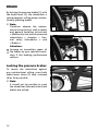
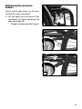
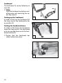
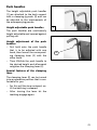
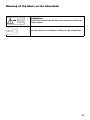
1
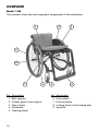
GB OPERATING MANUAL FOLDING WHEELCHAIR Model 1.360 Model 1.370 We move people. Contents Introduction................................................................................................... 5 Important information.........................................................................................6 List of models................................................................................................ 6 Indications...................................................................................................... 7 Acceptance..................................................................................................... 7 Specifications................................................................................................. 8 Use.................................................................................................................. 8 Adjustment.................................................................................................... 9 Reinstallment................................................................................................. 9 Life span......................................................................................................... 9 Overview...................................................................................................... 10 Model 1.360....................................................................................................10 Model 1.370....................................................................................................11 Brake............................................................................................................. 12 Locking the pressure brakes...............................................................................12 Releasing the pressure brakes............................................................................13 Leg supports................................................................................................ 14 Calf belt................................................................................................................14 Adjusting the calf belt...................................................................................14 Removing/attaching the calf belt.................................................................14 Lower leg support...............................................................................................15 Footplates.......................................................................................................15 Footboard.......................................................................................................16 Leg support upper part.......................................................................................17 Turning the leg supports to the side ...........................................................17 Swivelling in the leg supports.......................................................................17 Removing the leg supports...........................................................................18 Attaching the leg supports...........................................................................18 2 Clothes guard.............................................................................................. 19 Back support................................................................................................ 20 Back support belt................................................................................................20 Fitting the back belt......................................................................................20 Push handles........................................................................................................21 Height adjustable push handles...................................................................21 Height adjustment of the push handles......................................................21 Removing the push handles..........................................................................22 Inserting the push handles............................................................................22 Seat............................................................................................................... 22 Seat belt...............................................................................................................22 Utensils bag....................................................................................................22 Wheels.......................................................................................................... 23 Tyre damage on pneumatic tyres.......................................................................23 Drive wheels........................................................................................................23 Quick release axle..........................................................................................23 Quick release axle with tetra locking device Code 697..............................24 Support castors........................................................................................... 25 Swinging the support castors........................................................................25 Folding/Unfolding........................................................................................ 26 Folding the wheelchair.......................................................................................26 Carrying the wheelchair.....................................................................................26 Unfolding the wheelchair...................................................................................26 Transport...................................................................................................... 27 Transport security................................................................................................27 Transport of people inside a motor vehicle......................................................27 Maintenance................................................................................................ 28 Maintenance........................................................................................................28 Information for the specialist dealer............................................................28 Maintenance schedule...................................................................................29 3 Technical data.............................................................................................. 32 Model 1.360.........................................................................................................33 Model 1.370.........................................................................................................36 Meaning of the labels on the wheelchair.........................................................39 Meaning of the symbols on the type plate.......................................................40 Inspection certificate.................................................................................. 41 Warranty / Guarantee.................................................................................. 42 Inspection certificate for transfer......................................................................43 4 INTRODUCTION We thank you for the confidence you have placed in our company by choosing a wheelchair from this series. The model of your selection, fulfils the wish for mobility and more independence by way of a new styling of the proven MEYRA-Ortopedia technology. With all equipment and their accessories the wheelchair offers die respective adaptation to your disability. Additional information about our products can be found on our website under: Like any other vehicle, a wheelchair is a technical aid. It is subject to explanations, requires regular care and can cause danger when used improperly. The correct handling must therefore be learned. This operating manual is to help you get accustomed to the handling of the wheelchair as well as to prevent accidents. ☞Note: Please note that the illustrated equipment variants can deviate from your model. We have therefore also listed chapters with options that might not be applicable for your individual wheelchair. < www.meyra-ortopedia.com >. ☞Contact your specialist dealer when required. 5 Important information Attention: Read and observe the following documentation belonging to the wheelchair before first operation: ! – this operating manual, – the safety and general handling instructions < Mechanical and muscle powered wheelchairs >. ☞Note: Children and juveniles should read the documentation belonging to the wheelchair together with their parents respectively a supervisor or an accompanying person before first use. Users with visual impairments can find the PDF-files of above mentioned documents on our website under: < www.meyra-ortopedia.com >. ☞Contact your specialist dealer when required. Alternatively users with visual impairments can have the documentation read out by a helper. 6 LIST OF MODELS This operating manual applies to the following models: Model 1.360 Model 1.370 INDICATIONS ACCEPTANCE If the following indications occur we recommend the application of this mobility product: All products are checked for faults in the factory and packed in special boxes. ☞Walking disability resp. extremely ☞Note: limited walking ability as part of the basic need to move around in your own home. ☞The need to be able to leave home for a short walk in fresh air or in order to reach the places, commonly in the perimeter of the home, required to fulfil basic needs. ☞The ability to use the adaptive wheelchair with own personal strength must be given. However, we request that you check the vehicle for possible transport damage immediately on receipt – preferably in the presence of the carrier. ☞Note: The packaging of the wheelchair should be stored for a further transport that might become necessary. Provision with an adaptive wheelchairs can be an option, when the adaptation and adjustment possibilities of standard or lightweight wheelchairs are not sufficient. 7 SPECIFICATIONS USE The wheelchair was developed for adults and adolescents. The wheelchair is applicable on level, firm surfaces and can be used as follows: The wheelchair solely serves to transport one person in the seat and not as a hauling aid, transporter or similar. – for indoors (e.g. apartment, day care), – outdoors (e.g. paved paths in parks), – as a companion on tours (e.g. in a bus or train). The wheelchair offers manifold adjustment possibilities to individual vital statistics. The optimised crossbrace construction, apart from the small folding dimension, offers high stability. The wheelchair should be adapted to your needs by a specialist dealer before the first use. The adaptation will take into account the driving experience, the physical limits of the user and the main place of use of the wheelchair. Attention: Always have adaptation and adjustment work carried out by a specialist dealer. ! 8 ADJUSTMENT LIFE SPAN The specialist workshop will hand out the wheelchair to you under consideration of all relevant safety instructions, ready for operation and adjusted to your needs. We expect an average life span of about 4 years for this product, as far as the product is applied for its designated purpose and all maintenance and service guidelines. ☞Note: ☞We recommend a regular control The life span of your product depends upon the frequency of use, the application environment and care. if the wheelchair adjustment in order to ensure a long-term optimal provision even with changing illness/handicap patterns of the user. ☞We recommend regular medical exams in order to ensure safety for active participation in traffic. ☞Retrospective adjustments should The implementation of spare parts can prolong the life span of the product. As a rule spare parts are available up to 5 years after production is discontinued. ☞The indicated lifespan does not constitute additional guarantee. be carried out solely by the specialist dealer! REINSTALLMENT The wheelchair is suited for reinstallment. With the building block system the wheelchair can be fit to accommodate different handicaps body sizes. 9 OVERVIEW Model 1.360 The overview shows the most important components of the wheelchair. 1 2 3 9 8 7 6 5 4 Pos. Description Pos. Description 1 2 3 4 5 10 Back support Clothes guard / arm support Seat cushion Footboard Steering wheel 6 7 8 9 Drive wheel Pressure brake Locking knob / Quick release axle Handrim OVERVIEW Model 1.370 The overview shows the most important components of the wheelchair. 1 2 3 9 8 4 7 6 5 Pos. Description Pos. Description 1 2 3 4 5 Back support Clothes guard / arm support Seat cushion Leg support Steering wheel 6 7 8 9 Drive wheel Pressure brake Locking knob / Quick release axle Handrim 11 BRAKE By locking the pressure brakes [1] with the brake lever (2), the wheelchair is secured against rolling away unintentionally (parking brake). 2 ☞Note: Therefore observe the maintenance instructions as well as safety and general handling instructions < Mechanical and muscle powered wheelchairs > chapters < General safety information > and < Brakes >. 1 3 Attention: Arrange an immediate repair of the brakes by your specialist workshop if the braking performance reduces. ! Locking the pressure brakes To secure the wheelchair against any unintentional rolling, press both brake levers down (3) resp. outward (4) as far as possible. ☞Note: 12 It should not be possible to push the wheelchair forward when both brakes are locked. 4 Releasing the pressure brakes Swivel both brake levers up (5) resp. inward (6) as far as possible. ☞Do not grab into the area of the 5 crossbrace [7] when releasing the pressure brake (6). – Danger of jamming the fingers! 6 7 13 LEG SUPPORTS Attention: Before any actions on the leg supports the wheelchair is to be secured against unintentional rolling motions. – View chapter Brake on page 12. ! 1 Calf belt The calf belt (1) prevents the feet from sliding off the back of the footboard. Adjusting the calf belt – The calf belt is guided through the front frame tubes, view arrows [2], or around special attachment pins [3] and adjusted in length with a velcro strap. 2 Removing/attaching the calf belt – Removing and attaching the calf belt is achieved with the velcro fastener. Attention: Never drive without calf belt (except when shuffling)! ! ☞< Scuttling > is slow movement of the wheelchair with the feet. – For this the footboard is folded up. 14 3 Lower leg support For entry or exiting as well as „scutteling“ (the slow propulsion of the wheelchair with the feet) the footboard [1] / the footplates [2] can be folded upward. ☞Check the locking points! – Remove both feet from the footplates. 1 – Remove lower calf belt, if present. ☞Therefore observe chapter Calf belt on page 14. ☞Note: Before starting to drive the footboard / the footplates need to be folded back down [4] and the calf belt attached. 2 Footplates The footplates can be folded outward and up [2] resp. inward and down [4]. 3 4 15 Footboard The footboard [1] can be folded up to one side. ☞Note: Fold the footboard up before swivelling away and removing the upper leg support. Folding up the footboard 1 In order to fold up the footboard lift the loose end of the footboard as far as possible [2]. Folding the footboard down In order to fold down the footboard, lower the loose end of the footboard as far as possible down onto the footboard bracket [3]. ☞Ensure that the footboard has safely locked into place. 2 3 16 Leg support upper part The upper leg support with an inserted lower leg support is termed leg support. Turning the leg supports to the side For easy transfer out of/into the wheelchair as well as driving closer to a closet, bed or bathtub the leg supports can be swivelled away toward the in-/outside (1). 1 ☞Note: Before removing the leg supports remove the calf belt and fold the footplates up. ☞View chapter Calf belt on page 14 and chapter Lower leg support on page 15. 2 Attention: Leg supports turned to the side are released automatically and can easily come off. Note this when handling (e.g. transport). ! – Pull or press the respective locking lever (2) backward and swivel the corresponding leg support outward. Swivelling in the leg supports 3 For inward swivelling, let the leg supports swivel forward until the lock audibly engages [3]. ☞Note: After audibly swivelling the leg supports inward check the respective locking device. ☞Afterwards observe chapter Lower leg support on page 15. 17 Removing the leg supports For easy transfer into and out of the wheelchair as well as a reduced wheelchair length (important for transport) the leg supports can be removed [1]. ☞Note: Before removing the leg supports loosen or remove the calf belt on one side. ☞View chapter Calf belt on page 14. 1 First swivel the leg support sideways [2] and then remove them toward the top. ☞Therefore observe chapter Turning the leg supports to the side on page 17. Attaching the leg supports With the leg support in a swivelledaside position, hang it in and then swivel it to the front until the locking device audibly latches. ☞Note: After attachment swivel the leg supports inward. ☞Therefore observe chapter Swivelling in the leg supports on page 17. Press the leg supports, swivelled to the side, parallel to the front frame tube and lower it into place [2]. – In doing so the holding pin must slide into the frame tube. 18 2 CLOTHES GUARD The clothes guard [1] protects the clothes from the open spokes of the drive wheels and from spray water. Attention: No not grab between the clothes guard and tyre. – Danger of jamming! ! • • Do not lift or carry the wheelchair by holding on to the clothes guard / arm supports. 1 2 When the wheelchair is being pushed by an accompanying person the user is to place his hands onto the arm support pads (2) or in his lap and not at the sides between body and clothes guard. – Danger of squashing the fingers! 19 BACK SUPPORT Back support belt Fitting the back belt The tensioning of the back support [1] is adjustable. – Pull off the flap of the back support and fold it to the front [2]. 1 – Open the Velcro fastener of the belt (3) that you wish to adjust and close it again after adjustment. 3 Attention: The overlapping of the loop and hook strap has to be at least 10 cm! ! – Fold the flap of the back support back down and fasten it with the velcro fastener [4]. 2 4 20 Push handles The height adjustable push handles [1] are attached to the back support with a clamping jig each (2) and can be adjusted to the requirements of the accompanying person. Height adjustable push handles 1 The push handles are continuously height adjustable and secured against pulling out. Height adjustment of the push handles – First hold onto the push handle that is to be adjusted with one hand, then loosen the corresponding clamping lever (2) with the other hand. 2 – Then lift/slide the push handle to the desired height and afterwards retighten the clamping lever (2). Special features of the clamping lever The clamping lever (2) can be turned into an operation position that is comfortable for you. – For this pull the lever outward, until the teething is released. – After turning the lever let the teething engage again. 21 Removing the push handles Loosen the clamping lever (3) and pull the according push handle up as far as it will go. Press the respective spring button (4) inward and pull the push handle out of the clamping device (5). 5 3 4 Inserting the push handles Press down the spring button (4) and insert the push handle from the top into the respective clamping device (5). Slide the push handle through the clamping device (5) and retighten the clamping lever in the desired position (3). 1 SEAT Seat belt Utensils bag A storage pouch (1) with velcro fastener is located underneath the seat belt. In order to open the storage pouch (1) pull the leather latch down (2). To close the storage pouch press the front edge back up. 22 2 WHEELS Tyre damage on pneumatic tyres 1 ☞For repairing tyre damage we recommend the use of a foam cartridge that is available in speciality shops. – Afterwards look up a specialist workshop as soon as possible. Drive wheels The drive wheels are on a full quick release axle (1). ☞No person may be seated in the wheelchair during assembly or removal. The wheelchair must stand on a level and firm surface. Before starting the disassembly of a wheel, support the frame to prevent the wheelchair from tipping over and secure it to prevent an unwanted movement or tipping over. ☞Note: ☞After each assembly the locking device is to be checked with sideward pulling/pressing on the drive wheels! ☞If the drive wheels has too much sideward lag or the quick release axle does not engage, contact your specialist dealer immediately for repair. 2 Quick release axle The drive wheels can be removed and reassembled without any tools. – First press the locking knob (1) of the quick release axle in the center of the hub. – Afterwards remove or attach the drive wheel [2]. Attention: After inserting the drive wheel the locking knob (1) must stick a couple of millimetres out of the axle nut. ! 23 Quick release axle with tetra locking device Code 697 The drive wheels can be removed and reassembled without any tools. 1 Removing the drive wheel: – First turn the activation wheel (1) of the quick release axle as far as possible about 90° in the direction of the rim [2]. ☞The marker (3) faces in the direction of the rim when the quick release axle is released [2]. – Pull off the drive wheel [4]. 3 Attaching the drive wheel: – If necessary previously turn the activation wheel (1) as far as possible in the direction of the rim [2]. 2 – Slide the axle of the drive wheel as far as possible into the axle receptacle. – Afterwards turn the activation wheel (1) of the quick release axle by 90° in the direction of the center of the wheel hub (5). ☞The quick release axle is locked when the marker (3) is located centred to the wheel hub (5). 4 5 24 SUPPORT CASTORS The support castors [1] serve to raise the tilting stability and can be swivelled inward underneath the seat (2). ☞Depending on the version the support castors can be attached singly or as a pair. 1 Swinging the support castors Press the support castors out of the locking then swivel them inward until the lock engages automatically [2]. 2 25 FOLDING/UNFOLDING 3 Folding the wheelchair Your wheelchair can be folded in a few moments without tools being required [1]. – Remove the seat cushion, if applicable. 1 – Remove the calf belt if necessary. – Remove the leg supports or footboard, resp. fold up both footplates, view chapter Leg supports on page 14 – Bend the back belt to the rear. – Pull the seat belt upward in the centre of the front and back [1]. ☞Ensure that the folding fixation (3), if existent, engages correctly. Carrying the wheelchair Your wheelchair can be carried without difficulty when folded. – From the front push one lower arm under the upward folded seat belt. – Place other hand underneath the rear seat fold for support. – Lift the wheelchair to horizontal position. Unfolding the wheelchair For unfolding the wheelchair lift it slightly on one side and loosen the folding fixation (3), if existent. At the side resting on the floor, press the seat tube down to the end stop [2]. 26 2 ☞Note: ☞You may need to press down both seat tubes with the hands in order to do this. ☞Observe that the seat profile lies securely on the support surface. TRANSPORT Transport security The wheelchair is only to be secured through the four securing points [1] and (2). ☞The anchor positions are marked with the symbol (3). 1 ☞The procedure for securing the wheelchair can be read in the document < Safety and general handling instructions < Mechanical and muscle powered wheelchairs > chapter < Transport in motor vehicles or conveyors >. 2 Transport of people inside a motor vehicle To determine if your wheelchair is approved as a seat for transport inside a motor vehicle, please look at the type plate of your wheelchair. Attention: Subsequently, firmly attached components of non-original parts on your wheelchair are not approved for person transportation within a motor vehicle. ! 3 27 MAINTENANCE ☞Note: An incorrect or neglected cleaning and maintenance results in a limitation of the product liability. Maintenance The following maintenance schedule gives you a guide for carrying out the maintenance. ☞They do not give information about the actual extent of work required on the vehicle. Information dealer for the specialist The maintenance and service manual for this product can be found on our website under: < www.meyra-ortopedia.com >. You can for example find the following information in these manuals: 1. Adjustments that can be carried out with tools. 2. Step by step explanations to important repairs. 3. Information on model specific amendments. 4. A checklist for the annual inspection. The functional tests necessary for the inspection are listed in the check list. They are a guide for the performance of the inspection work. 28 It does not outline the actual scope of the necessary work which can only be ascertained by an inspection of the vehicle. After the successful completion of an annual inspection the inspection certificate should be recorded in the operating manual. Maintenance schedule WHEN Before out starting WHAT REMARK Test brakes for faultless operation Carry out test yourself or with a helper. Activate brake lever to the limit. The locked wheels should not be able to turn under operating conditions. If they can still turn, the brakes must be repaired by an authorised specialist workshop. Before out starting Check pressure brake for wear Move brake lever to the side Carry out tests yourself or have a helper do it. If you notice any increasing slackness on the brake lever take the wheelchair to your specialist workshop immediately for repairs. – Danger of accident! Do it yourself or with the aid of a helper. Before starting out (when applicable) Check air pressure of the tyres WHEN WHAT REMARK Before starting out Especially before driving in the dark Check the lighting Carry out test yourself or with a helper. For this use an air pressure gauge or, if not available, „Thumb-pressure-method“ or similar (view < Brakes > in document Safety- and general handling instructions < Mechanical and muscle powered wheelchairs >. Check the lighting equipment and reflectors for flawless functioning. 29 WHEN WHAT REMARK Every 2 months (depending on distance covered) Check frame tubes for damage Carry out test yourself or with a helper. If deformations or cracks occur in the welding seams, contact a specialist workshop immediately for repairs. – Danger of accident! Every 2 months (depending on distance covered) Lubricate the following components with a few drops of oil Do it yourself or with the aid of a helper. Components must be free from used oil residues before lubrication. Please ensure that excess oil does not contaminate the environment (e.g. your clothing). – Bearing brace. of cross- – Moving parts of the locking mechanism. – Brake ings. Every 2 months (depending on distance covered) lever bear- Check all screw connections for secure fit Carry out test yourself or with a helper. The following is to be checked with great care: – Attachment of the back and seat belt, – Attachment of the footboard. Every 2 months (depending on distance covered) 30 Check tyre profile Minimum tread = > 1 mm Carry out a visual check yourself or with a helper. If the tyre profile is worn down or if the tyre is damaged, consult a specialist workshop for repairs. WHEN WHAT Every 6 months (depending on frequency of use) Check Manufacturer recommendation: Every 12 months (depending on frequency of use) – Cleanness. – General condition. Maintenance jobs – Vehicle REMARK View < Maintenance > in document Safety- and general handling instructions < Mechanical and muscle powered wheelchairs >. To be carried out by the specialist dealer. 31 TECHNICAL DATA Tyre filling pressure: All model dependent specifications within the < Technical data > refer to the standard version of the respective models. Full tyre pressure – steering wheel The overall length depends on the position and size of the drive wheels. If not noted otherwise the dimensions are determined with drive wheels of ø 610 mm (24“). The widths were determined with a handrim distance of 15 mm. Dimensional tolerance ± 1.5 cm, ± 2°. Short form of wheelchair dimensions: SH = Seat height SW = Seat width SD = Seat depth BH = Back support height Calculation of the max. user weight: Attention: The permissible total weight is calculated from the empty weight of the wheelchair and the maximum user- (person-) weight. ! Additional weight due to subsequent additions or luggage reduce the maximum permissible user weight. Example: A driver wishes to take luggage with a weight of 5 kg. Thus, the maximum user weight is reduced by 5 kg. 32 Maximum tyre pressure is printed on the tyres on each side. Standard: 2.5 - 3.5 bar = 36 - 50 psi Full tyre pressure – drive wheel Standard: 3.0 - 4.0 bar = 44 - 58 psi Ultra-light running tyres: 6 bar = 87 psi High pressure: 8 bar = 116 psi Model 1.360 All data within the following table relates to the standard version of the stated model. Dimensional tolerance ± 1.5 cm, ± 2°. Model:................................................................................................................1.360 Type plate:............................................................................... at the crossbrace tube Life span:........................................................................................................... 4 years Dimensions Dimensions:.......................................... min. / max. / manufacturer setting Overall length (frame Code 346): Short frame:................................................................................... 840 / 910 / ---- mm Medium frame:.............................................................................. 880 / 950 / ---- mm Long frame:.................................................................................... 920 / 990 / ---- mm Overall length (frame Code 347): Short frame:................................................................................... 810 / 880 / ---- mm Medium frame:.............................................................................. 850 / 920 / ---- mm Long frame:.................................................................................... 890 / 960 / ---- mm Overall width: w wheel camber 0.5°:..................................................................... 510 / 670 / --- mm w wheel camber 3°:........................................................................ 560 / 720 / --- mm Overall height:.............................................................................. 650 / 1000 / --- mm Back strap height adjustable by +2.5 cm each: Standard/adjustable back support strap:............................................ 25 / 50 / --- cm Seat width:...................................................................................... 340 / 500 / --- mm Seat depth (short frame 380 - 420 / medium 440 - 460):............. 380 / 460 / --- mm Seat depth (long frame):................................................................ 480 / 500 / --- mm Seat height, without cushion: Seat surface height at front edge:................................................ 460 / 520 / --- mm Height of armrests: from seat surface:................................................................................. 15 / 29 / --- cm Back support to front edge of arm support:...................................... 27 / 27 / --- cm Seat cushion thickness:......................................................................................... 3 cm Push handle height Code 502: continuously adjustable:...........................................................................max. 15 cm 33 Dimensions:.......................................... min. / max. / manufacturer setting Back support angle: bent at manufacturer (firm):................................................................ 84° / 96° / 96° Seat tilt:...................................................................................................... 0° / 15° / --Leg support angle: Code 346.................................................................................................................. 77° Code 347.................................................................................................................. 85° Foot support to seat, without seat cushion (lower shank length): with foot board:................................................................................... 39 / 48 / --- cm Wheels Steering wheel: ø 100 x 30 mm:......................................................................................... solid rubber ø 125 x 30 mm:......................................................................................... solid rubber ø 142 x 37 mm:......................................................................................... solid rubber Drive wheel (pneumatic tyres): ø 596 mm (24 x 1“):.......................................................................................... 8.0 bar ø 616 mm (24 x 1 3/8“):.................................................................................... 4.0 bar ø 596 mm (24 x 1“):...............................................................................puncture safe ø 610 mm (24 x 1 3/8“):.........................................................................puncture safe Handrim diameter:..........................................................................................53.5 cm Wheel camber:.......................................................................................... 0.5° / 3° / --Axle horizontal position: Active:................................................................................................ 80 / 100 / 80 mm Middle:................................................................................................ 50 / 70 / 50 mm Passive:................................................................................................. 30 / 50 / 30 mm Transport dimensions Folding length:................................................................................ 810 / 910 / --- mm Length without drive wheels:........................................................................ 610 mm (Support castors are removed or swivelled underneath the seat) Folding width: w wheel camber 0.5°:..................................................................................... 300 mm w wheel camber 3°:........................................................................................ 350 mm Folding height:.............................................................................. 650 / 1000 / --- mm 34 Permitted inclination/slopes max. obstacle height (depending on the setting of the leg support height):.................................................................................0 to 100 mm min. turning radius diameter:..................................................................... 1100 mm Max. permissable rising gradient:.............................................................. 4.5° (8 %) Max. permissable falling gradient:............................................................ 4.5° (8 %) Max. permissable transverse gradient:...................................................... 4.5° (8 %) static tilting safety in all directions:............................................................ 6° (10 %) Climatic data: Ambient temperature:...................................................................... -25 °C to +50 °C Storage temperature:........................................................................ -40 °C to +65 °C Weights Permissible total weight:......................................................................... max. 129 kg max. user weight (including additional load):...................................... max. 120 kg Max. additional loading:.....................................................................................10 kg Empty weight:...............................................................................min. 9 / max. 15 kg Heaviest single component: Drive wheel:........................................................................................................2.2 kg Transport weight:...................................................................................... min. 6.5 kg (without arm supports, cushion, drive wheels) 35 Model 1.370 All data within the following table relates to the standard version of the stated model. Dimensional tolerance ± 1.5 cm, ± 2°. Model:................................................................................................................1.370 Type plate:............................................................................... at the crossbrace tube Life span:........................................................................................................... 4 years Dimensions Dimensions:.......................................... min. / max. / manufacturer setting Overall length (with leg support): Short frame:................................................................................... 900 / 980 / ---- mm Medium frame:............................................................................ 920 / 1020 / ---- mm Long frame:.................................................................................. 960 / 1060 / ---- mm Extra long frame:....................................................................... 1000 / 1100 / ---- mm Overall length (w/o leg support): Short frame:................................................................................... 720 / 800 / ---- mm Medium frame:.............................................................................. 740 / 840 / ---- mm Long frame:.................................................................................... 780 / 880 / ---- mm Extra long frame:........................................................................... 820 / 920 / ---- mm Overall width: w wheel camber 0.5°:..................................................................... 490 / 690 / --- mm w wheel camber 3°:........................................................................ 540 / 740 / --- mm Overall height:.............................................................................. 650 / 1000 / --- mm Back strap height adjustable by +2.5 cm each: Standard/adjustable back support strap:............................................ 25 / 50 / --- cm Seat width:...................................................................................... 320 / 520 / --- mm Seat depth (short frame):............................................................... 360 / 400 / --- mm Seat depth (medium frame):......................................................... 420 / 440 / --- mm Seat depth (long frame):................................................................ 460 / 480 / --- mm Seat depth (extra long frame):...................................................... 500 / 520 / --- mm Seat height, without cushion: Seat surface height at front edge:................................................ 460 / 540 / --- mm 36 Height of armrests: from seat surface:................................................................................. 15 / 29 / --- cm Back support to front edge of arm support:...................................... 27 / 27 / --- cm Seat cushion thickness:......................................................................................... 3 cm Push handle height Code 502: continuously adjustable:...........................................................................max. 15 cm Back support angle: bent at manufacturer (firm):................................................................ 84° / 96° / 96° Seat tilt:...................................................................................................... 0° / 15° / --Leg support angle: Code 93.................................................................................................................... 77° Foot support to seat, without seat cushion (lower shank length): with single footplates:......................................................................... 37 / 51 / --- cm Wheels Steering wheel: ø 100 x 30 mm:......................................................................................... solid rubber ø 125 x 30 mm:......................................................................................... solid rubber ø 142 x 37 mm:......................................................................................... solid rubber ø 180 x 40 mm:...................................................................................pneumatic tyres Drive wheel (pneumatic tyres): ø 596 mm (24 x 1“):.......................................................................................... 8.0 bar ø 616 mm (24 x 1 3/8“):.................................................................................... 4.0 bar ø 646 mm (26 x 1“):.......................................................................................... 8.0 bar ø 596 mm (24 x 1“):...............................................................................puncture safe ø 610 mm (24 x 1 3/8“):.........................................................................puncture safe Handrim diameter (24"/26"):.................................................................53.5/ 58.5 cm Wheel camber:.......................................................................................... 0.5° / 3° / --Axle horizontal position: Active:................................................................................................ 80 / 100 / 80 mm Middle:................................................................................................ 50 / 70 / 50 mm Passive:................................................................................................. 30 / 50 / 30 mm 37 Transport dimensions Folding length:.............................................................................. 880 / 1100 / --- mm Length without drive wheels, without leg supports:.................. 530 / 850 / --- mm (Support castors are removed or swivelled underneath the seat) Folding width: w wheel camber 0.5°:..................................................................................... 300 mm w wheel camber 3°:........................................................................................ 350 mm Folding height:.............................................................................. 650 / 1000 / --- mm Permitted inclination/slopes max. obstacle height (depending on the setting of the leg support height):.................................................................................0 to 100 mm min. turning radius diameter:..................................................................... 1200 mm Max. permissable rising gradient:.............................................................. 4.5° (8 %) Max. permissable falling gradient:............................................................ 4.5° (8 %) Max. permissable transverse gradient:...................................................... 4.5° (8 %) static tilting safety in all directions:............................................................ 6° (10 %) Climatic data: Ambient temperature:...................................................................... -25 °C to +50 °C Storage temperature:........................................................................ -40 °C to +65 °C Weights Permissible total weight:......................................................................... max. 160 kg max. user weight (including additional load):...................................... max. 150 kg Max. additional loading:.....................................................................................10 kg Empty weight:..........................................................................min. 10.5 / max. 18 kg Heaviest single component: Drive wheel:........................................................................................................2.2 kg Transport weight:...................................................................................... min. 6.5 kg (without arm supports, cushion, drive wheels, leg supports) 38 Meaning of the labels on the wheelchair Attention! Read the operating manuals and other provided documentation. Anchor point for transport safety of the wheelchair. 39 Meaning of the symbols on the type plate Manufacturer Order number Serial number Production date (Year – Calendar week) Permitted user weight Max. permissible total weight Permitted axle loads Max. permissible rising gradient Max. permissible falling gradient Max. permitted final speed The product is approved as a seat within a motor vehicle. X 40 The product is not approved as a seat within a motor vehicle. INSPECTION CERTIFICATE Vehicle data: Model: Delivery note no.: Serial-no. (SN): Recommended safety inspection 1st year (at least every 12 months) Recommended safety inspection 2nd year (at least every 12 months) Stamp of specialist dealer: Stamp of specialist dealer: Signature: Signature: Place, date: Place, date: Next safety inspection in 12 months Next safety inspection in 12 months Date: Date: Recommended safety inspection 3rd year (at least every 12 months) Recommended safety inspection 4th year (at least every 12 months) Stamp of specialist dealer: Stamp of specialist dealer: Signature: Signature: Place, date: Place, date: Next safety inspection in 12 months Next safety inspection in 12 months Date: Date: 41 WARRANTY / GUARANTEE tions cannot be declared as warranty or guarantee claims. We accept legal liability for this product within the scope of or general terms and conditions and warranty and the guarantee according to our described quality service. For warranty and guarantee demands please contact your specialist dealer with following Warranty/Guarantee section and the there included information on model description, delivery note number with delivery date and serial number (SN). The serial number (SN) can be read off of the type plate. Precondition for the acceptance of liability in any case is the intended use of the product, the use of original spare parts by specialist dealers as well as maintenance and inspections in regular intervals. Attention: Failure to observe the instructions in the operating manual, improperly carried out maintenance work and, especially, technical changes and additions (add-ons) carried out without our prior consent will lead to a general loss of guarantee and product liability. ! ☞ Note: This operating manual as a part of the product is to be handed out in case of a change of user or owner. We reserve the right to make technical improvements. Guarantee is not granted for surface damages, tyres of the wheels, damages due to loosened screws or nuts as well as worn out attachment holes due to frequent assembly work. Interferences through radiation sources such as mobile phones with high transmission power, HiFi-equipment and other extreme interference radiators outside of norm specifica- The product conforms with the EC Directive 93/42/EEC (MDD) for medical products. 42 WARRANTEE / GUARANTEE SECTION Please fill out! Copy if necessary and send the copy to the specialist dealer. Warranty / Guarantee Model designation: Delivery note no.: SN (view type plate): Date of delivery: Stamp of the specialist dealer: Inspection certificate for transfer Vehicle data: Serial-no. (SN): Model: Stamp of specialist dealer: Signature: Place, date: Delivery note no.: Next safety inspection in 12 months Date: 43 Your specialist dealer: We 44 move people. MEYRA-ORTOPEDIA Vertriebsgesellschaft mbH Meyra-Ring 2 · D-32689 Kalletal-Kalldorf P.O. Box 1 703 • D-32591 Vlotho Fon +49 (0)5733 922-311 Fax +49 (0)5733 922-9311 [email protected] www.meyra-ortopedia.de 205 338 501 • (Status: 2012-09) All technical modifications reserved!